thrust force and torque in the drilling process laminated...
TRANSCRIPT

248
Annals of Warsaw University of Life Sciences - SGGW Forestry and Wood Technology № 88, 2014: 248-254 (Ann. WULS - SGGW, For. and Wood Technol. 88, 2014)
Thrust force and torque in the drilling process laminated chipboard JOANNA ZIELIŃSKA-SZWAJKA 1), KRZYSZTOF SZWAJKA 2) 1)PATENTUS STREFA S.A. 1) Rzeszow University of Technology, Faculty of Mechanical Engineering and Aeronautics
Summary: Thrust force and torque in the drilling process laminated chipboard. Particleboard is a wood based composite extensively used in wood working. Drilling is the most commonly used machining process in furniture industries. The surface characteristics and the damage free drilling are significantly influenced by the machining parameters. The thrust force developed during drilling play a major role in gaining the surface quality and minimizing the delamination tendency. In this study trials were made eighteen durability tools for different values of the parameters analyzed cut. Based on the results obtained from the study, the effect of cutting parameters selected signals of axial force and torque cutting. Proposed mathematical models using ANOVA, allowing to estimate the cutting forces.
Keywords: drilling, feed force, cutting torque, tool wear, laminated chipboard
INTRODUCTION Particleboard is mainly used for furniture, in flooring, and as panels. Particleboard is a
result of the need to utilize large quantities of sawdust at sawmills. Particleboard is usually produced from softwoods and used in panel form. Wood particles are bonded using synthetic adhesives and pressed into sheets. Typically, particleboard consists of a lower density core of coarse particles and outer, higher density layers of finer particles. The board performance is greatly influenced by the distribution of density and particle size [1]. Many applications involve bending loads, where a high-density skin and a low-density core are advantageous. The particleboard panel functions as a sandwich structure and the ratio of bending stiffness to weight becomes high. Machining of wood-based materials causes cutting tools to wear out much faster than machining of solid woods. The use of tungsten carbide tool is also limited because of the relatively high rate of wear [2]. The tungsten carbides were liable to wearing during cutting particleboard and fiberboard due to high temperature oxidation and abrasion [3,4]. The machining of particleboards is known to be very difficult because of extremely short tool life [5–8]. The influence of content of mineral contamination has been discussed as the major factor involved in the wearing process of cutting edges during the machining of particleboards [5,6,9] and high-temperature corrosion (HTC) was pointed out as a second important factor impacting tool wear during cutting of particleboards [10]. The density affects most of the physical and mechanical properties of wood composite panels [11–13]. Panel density has been shown to have a considerable impact on flexural properties of wood-based composites [14].
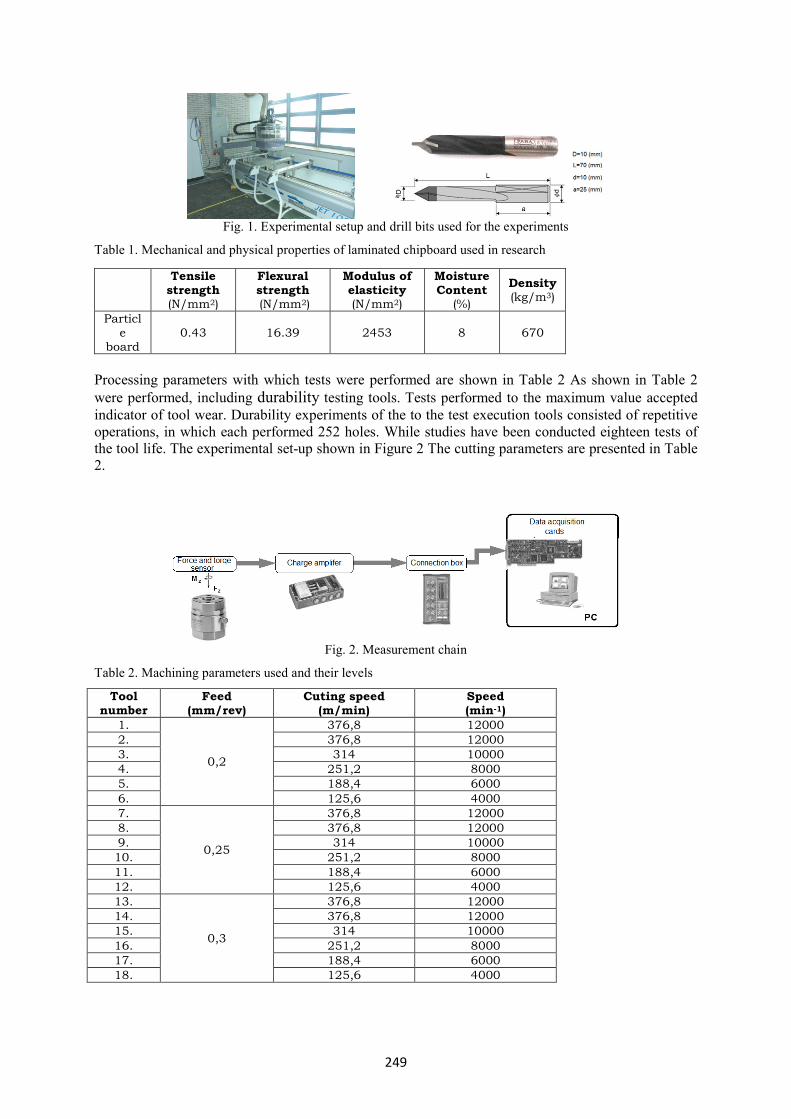
MATERIAL AND METHODS The experiments are performed on pre-laminated PB of 12 mm thickness with Faba HW
drills of diameter 10mm on Buselatto JET 130 CNC vertical machining center with a maximum spindle speed of 18,000 rpm. Experimental set up and drills used for the experiments are shown in Figure 1. Table 1 depicts the properties of PB composites tested.
249
Fig. 1. Experimental setup and drill bits used for the experiments
Table 1. Mechanical and physical properties of laminated chipboard used in research
Tensile strength (N/mm2)
Flexural strength (N/mm2)
Modulus of elasticity (N/mm2)
Moisture Content
(%)
Density (kg/m3)
Particle
board 0.43 16.39 2453 8 670
Processing parameters with which tests were performed are shown in Table 2 As shown in Table 2 were performed, including durability testing tools. Tests performed to the maximum value accepted indicator of tool wear. Durability experiments of the to the test execution tools consisted of repetitive operations, in which each performed 252 holes. While studies have been conducted eighteen tests of the tool life. The experimental set-up shown in Figure 2 The cutting parameters are presented in Table 2.
Fig. 2. Measurement chain
Table 2. Machining parameters used and their levels
Tool number
Feed (mm/rev)
Cuting speed (m/min)
Speed (min-1)
1.
0,2
376,8 12000 2. 376,8 12000 3. 314 10000 4. 251,2 8000 5. 188,4 6000 6. 125,6 4000 7.
0,25
376,8 12000 8. 376,8 12000 9. 314 10000 10. 251,2 8000 11. 188,4 6000 12. 125,6 4000 13.
0,3
376,8 12000 14. 376,8 12000 15. 314 10000 16. 251,2 8000 17. 188,4 6000 18. 125,6 4000

250
To further characterize the workpiece conducted laboratory measuring its local density (Fig. 3).
Fig. 3. Medium density profile for laminated chipboard and photo scanning
MEASUREMENT The main element of the measurement channel was 9345B2-type piezoelectric sensor
with preamplifier charge 5073A211 company KISTLER. For the analysis of test results prepared own computer program (LabView programming language) allows the selected pieces on the time taken to determine the values recorded signal strength measurements.
The program was based on the automatic determination of measurement recorded signals at specific periods of time signal. As soon as the signal exceeds the axial force Fz, the threshold adopted at the level of 150mV, followed the appointment of selected measures (mean, RMS) of both signals. Determination of these measures lasted until the point at which the signal value of the axial force decreased poniżej150 mV. Doing so gives reproducible signal time segment on the basis of the measurement are calculated. A simplified diagram of the determination of measurement signals is shown in Figure 4.
Fig. 4. Method of determining a signal strength measurement Fz and torque Mz
In our studies as a tool wear indicator adopted VBmax = 0.2 mm. Measurement of consumption made on the microscope Mitutoyo TM. with drop-on eyepiece digital camera with a resolution of 600 dpi, which allows image archiving tool performed on a personal computer. Processing parameters with which tests were carried out are summarized in Table 2 for each adopted in the study, the feed was carried out on six samples for five-speed durability of cutting. As shown in Table 18 were performed, including durability testing tools. Tests were carried out to the maximum value accepted indicator of blade wear. At every attempt durability tools consisted of repetitive execution of operations in which each performed 252 holes. After each completed operation, followed by a measurement of tool wear and registration signal axial force (Fz), as well as cutting torque (Mz) is performed for the cutting

251
parameters as in experiment durability, but also in addition to the two test plan adopted in feed value.
THE TEST RESULTS Figure 5 presents examples obtained during the investigation waveforms axial force and
torque cutting. for new tools and wear tools in a sample of durability.
Fig. 5. Exemplary signal waveforms axial force Fz and moment cutting Mz.
Presented below the results of the study, which analyzed the axial force (Fz), and cutting
moment (Mz) using three different feed rates (f), five-speed (vc) and three compartments of tool wear (VBmax). The analysis of the obtained results, it was decided to determine the effect of feed rate, tool wear and cutting speed on the value of the axial force and torque cutting. For the present experiment, ANOVA was performed with the package STASTISTICA program, which sets out the significance of the impact of three factors on the course of the controlled experiment. To investigate the effect on test feature VBmax factor, factor fi vc factor model is adopted, called the tripartite classification model. The analysis (Fig. 6) rejected (at significance level p = 0.000) hypothesis about the lack of impact factor and the factor f VBmax the value of the force signal (Fz). So we can say that the value of tool wear and feed significantly affect the value of the signal strength in drilling. It is noted here as well (at the significance level p = 0.029) effect of cutting speed (vc) in the value of the force signal (Fz). There was an interaction (statistically significant) between the studied factors.
Fig. 5. The influence of cutting parameters on the value of the axial force (Fz)

252
The analysis (Fig. 6) rejected (at significance level p = 0.000) hypothesis about the lack of impact factor and the factor f VBmax, and vc factor (at significance level p = 0.020) on the value of the torque cut (Ms). So we can say that the value of tool wear and feed, as well as cutting speed significantly affect the cutting torque in drilling. In addition, it is highly significant (p = 0.000) interaction of the factors to consider (VBmax, vc).
Fig.6. The influence of cutting parameters on the value of the moment cutting (Mz)
Design of cutting tools, especially with complex shapes, such as drills, cutters shaped like., Should be preceded by the optimization process. This requirement is often due to optimization of the fact that the two conflicting criteria must be taken into account at the design stage. This is best illustrated by an ordinary drill, where on one side of the flute cross-section should be as large as possible (this facilitates the discharge of a large quantity of chips) on the other hand, the cross section of the core should be large to increase mechanical strength of the drill, and thus allow the use of higher cutting. Both criteria are mutually contradictory, because of the increase in the diameter of the drill bit flute cross-sectional area helps to reduce the cross-sectional area of the core drill, and vice versa. So finding a compromise solution requires action optimization. Take the optimization procedure is subject to the earlier diagnosis of the state of charge of such a tool, ie. Distribution of forces and moments resulting from the process of the chip and affecting the cutting edges of the tool. Well, in this matter in the machining of large gaps observed as evidenced by the modest information on both the numerical values of the cutting forces and the distribution of this load along the cutting edge. Until now dominated by empirical formulas, statistical, which allow the estimation of some alternative (accident) forces, for example. Axial force or torque Fz Mz cut by the relationship:
FFF zc
yxFo vfVBCF ***=
(1) zM
cyMxM
Ms vfVBCM ***= (2) Assessed the studies performed, an estimate of the signal values of axial force and torque cutting. This resulted in dependence described equations 3 and 4.
02.033.037.0 ***1518 co vfVBF =
(3)

253
19.185.047.0 ***1400 cs vfVBM = (4)
In order to verify the derived equation (3 and 4) a comparative analysis between the actual values, obtained in the course of the study, and the values are estimated, on the basis of these relationships. The results of this analysis are shown in Figure 7.
Fig. 7. Real value and the estimated value of the axial force Fz signal and the signal moment cutting Mz
CONCLUSION On the basis of the analysis and received on the basis of its dependencies 3 and 4 it can be
seen that the signal of the axial force (Fz) strongly depends on both the tool wear and feed rates. The influence of the cutting speed can be omitted here (due to the fact that the exponent depending vc 3 is close to zero). In the case of cutting torque signal (Mz) can be observed a significant effect of all three independent variables (see relationship 4) the value of the signal.
BIBLIOGRAPHY [1] L. Berglund, R.M. Rowell, Wood Composites-Handbook of Wood Chemistry and Wood Composites, CRC Press, USA, 2005 (Chapter 10). [2] W. Darmawan, H. Usuki, J. Quesada, R. Marchal, Clearance wear and normal force of TiN-coated P30 in cutting hardboards and wood-chip cement boards, Holz Roh Werkst 66 (2008) 89–97. [3] H.A. Stewart, High-temperature halogenation of tungsten carbide cobalt tool material when machining medium density fiberboard, Forest Prod. J. 42 (10) (1992) 27–31. [4] J.Y. Sheikh-Ahmad, J.A. Bailey, High-temperature wear of cemented tungsten carbide tools while machining particleboard and fiberboard, J. Wood Sci. 45 (6) (1999) 445–455. [5] R.R. Bridges, A quantitative study of some factors affecting the abrasiveness of particle board, Forest Prod. J. 11 (1971) 39–41. [6] B. Porankiewicz, Variation in composition of micro-grain cemented carbide and its impact on cutting edge wear during particleboard machining, in: Proc. 13th IWMS, Vancouver, Canada, 1997, pp. 791–799. [7] B. Porankiewicz, A. Gronlund, Tool wear–influencing factors, in: Proc. 10th IWMS, UC, Berkeley, USA, 1991, pp. 220–229. [8] B. Porankiewicz, A method to evaluate the chemical properties of particleboard to anticipate and minimize cutting tool wear, Wood Sci. Technol. 37 (1) (2003) 47–58. doi:10.1007/s00226-003-0166-8. [9] A.J. Sparks, V. Taylor, Chip board machinibility, Part 1, the effect of cut on cutter wear, Furniture Industry Research Association, No. 928/ 271/81, 1981. [10] B. Porankiewicz, Investigation of chemical wear of cemented carbide cutting edges by processing board materials, Project Report No. MR/ USDA-95-219, 1998, pp. 32. [11] T.M. Maloney, Modern particleboard and dry-process fiberboard manufacturing, Miller Freeman, San Francisco, 1993.

254
[12] O. Suchsland, G.E. Woodson, Fiberboard manufacturing practices in the United States, Agriculture Handbook, No. 640, United States Department of Agriculture, 1986. [13] M.W. Kelly, Critical literature review of relationships between processing parameters and physical properties of particleboard, Gen. Tech. Rep. FPL-10, Forest Products Laboratory, Forest Service, US, Department of Agriculture, USA, 1977, pp. 66. [14] S. Chen, X. Liu, L. Fang, R. Wellwood, Digital X-ray analysis of density distribution characteristics of wood-based panels, Wood Sci. Technol. 44 (2010) 85–93. Streszczenie: Siła osiowa i moment skrawania w procesie wiercenia płyty wiórowej laminowanej. Płyta wiórowa jest kompozytem na bazie drewna szeroko wykorzystywane w przemyśle. Proces wiercenia jest najczęściej stosowanym procesem obróbki w przemyśle meblarskim. Siła osiowa i moment skrawania występujące podczas procesu wiercenia odgrywają ważną rolę w uzyskaniu odpowiedniej jakość powierzchni. W przeprowadzonych badaniach wykonano osiemnaście prób trwałościowych narzędzia dla różnych wartości analizowanych parametrów skrawania. Na podstawie wyników uzyskanych z przeprowadzonych badań określono wpływ wybranych parametrów skrawania na sygnały siły osiowej i momentu skrawania. Zaproponowano modele matematyczne, wykorzystując analizę wariancji ANOVA, pozwalający oszacować opory skrawania.
Corresponding authors: Joanna Zielińska-Szwajka PATENTUS STREFA S.A. 37-450 Stalowa Wola Kwiatkowskiego 1 str. Poland [email protected] Krzysztof Szwajka Rzeszow University of Technology Faculty of Mechanical Engineering and Aeronautics 37-450 Stalowa Wola Kwiatkowskiego 4 str. [email protected]