tightly arranged orthogonal mode antenna for 5g mimo
TRANSCRIPT

Received: 14 November 2017
DOI: 10.1002/mop.31240
Tightly arranged orthogonalmode antenna for 5G MIMOmobile terminal
Libin Sun1 | Haigang Feng2 |
Yue Li1 | Zhijun Zhang1
1State Key Laboratory on Microwave and Communications, TsinghuaNational Laboratory for Information Science and Technology, TsinghuaUniversity, Beijing 100084, China2Graduate school at Shenzhen, Tsinghua University, Shenzhen 518055,China
CorrespondenceZhijun Zhange, State Key Laboratory on Microwave and Communications,Tsinghua National Laboratory for Information Science and Technology,Tsinghua University, Beijing 100084, China.Email: [email protected]
Funding informationNational Natural Science Foundation of China, Grant/Award Number61525104; China Postdoctoral Science Foundation, Grant/Award Number:2015T80084
AbstractThis letter presents an orthogonal mode 4-antenna sys-tem operating in the 3.5-GHz band (3.3–3.6 GHz) forthe fifth-generation (5G) multiple-input multiple-output(MIMO) mobile device. The 4-antenna system is com-posed of 2 identical tightly arranged antenna pairs, andeach pair is formed with an arrow-shaped monopole anda bended dipole with gap-coupled feeding. The tightly-arranged antenna pair is face-to-face arranged on thefront and back side of the substrate and the distancebetween the center of the 2 elements is only 1 mm; how-ever, they have good isolation (better than 10 dB) anddiversity performance (envelope correlation coefficientbetter than 0.11) with the help of orthogonal mode. Thisconfiguration provides promising solution for compact-ness of the MIMO antenna in mobile phone. Theprototype was fabricated and measured, and the meas-ured results show good agreements with the simulatedones.
KEYWORD S
fifth-generation (5G), mobile antenna, multiple-input multiple-output
(MIMO), orthogonal mode, tightly arranged
1 | | INTRODUCTION
With the rapid development of mobile communication, thedemand for the capacity of wireless communication is strong.To satisfy the demand, multiple-input multiple-output(MIMO) technology, as a key technology of fifth-generation(5G) communication, provides a promising solution forenhancing the communication channel capacity. And thereare an increasing number of commercial mobile phones usedMIMO technology to improve the performance of mobilecommunication. Although MIMO technology can provide apleasing performance for mobile communication, how tointegrate a lot of antennas in a limited region with good iso-lation is a challenging task. It has been noted that the fre-quency spectrum 3.5 GHz has become one of the 5G bandsin the World Radio-communication Conference 2015.1 Andvery recently, the frequency spectrum 3.3–3.6 GHz has beenidentified preliminarily for 5G mobile communication byChina ministry of industry and information technology.2
Recently, a number of publications presented the mobilephone antenna for 5G MIMO application.3-9 The first 8 3 8MIMO mobile phone antenna operating at 3.5 GHz is pro-posed in3 with 8 capacitive coupling elements; however, themutual coupling across the required band of the MIMOantenna is not presented in this paper. In reference,4 a3.5 GHz 10 3 10 MIMO mobile phone antenna with theopen slot structure has been investigated, and the 10 dB iso-lation is obtained with the help of large distance (center tocenter distance 23 mm) between antenna elements. A 8 3 8and 16 3 16 MIMO antenna with the same element structurehas been presented in5 using the neutralizing line to enhanceisolation of the antenna element. The center-to-center dis-tance of 2 antenna elements is 11 mm with the help of neu-tralizing line, which makes an intensively improvementcompared with.4 Two asymmetrically mirrored gap-coupledloop antennas are used to form 8 3 8 MIMO mobile phoneantenna,6,7 and the 2 asymmetrically mirrored antenna ele-ments are mounted along one edge of the system groundplane, so that the edge-to-edge distance of 2 elements is0.8 mm and the center to center distance is 3.9 mm. Withsuch a tiny region occupied, a current cancellation method,which is similar to the principle of neutralizing line wasinvestigated to achieve the isolation better than 10 dB acrossthe 3.4–3.6 GHz. Furthermore, an orthogonal polarizationmethod to decrease the mutual coupling of the 5G MIMOelements is described in8; however, the distance between theorthogonal polarization antenna pair is still large. In refer-ence,9 a dual polarization loop structure with good isolationperformance and no ground clearance is described, whichmeans 2 MIMO elements only occupy 1 antenna structure’sregion. Polarization diversity technology is a promising wayto reduce the mutual coupling of the MIMO antenna
SUN ET AL. | 1751

elements, even though the antenna elements are close to eachother. There are a large number of publications achievingdesirable isolation due to orthogonal polarization;10–12 how-ever, the orthogonal polarization technology is rarely appliedin 5G MIMO mobile phone antenna.8 Thus, we can achievea desirable isolation by 2 orthogonal mode elements withtiny element distance.
In this letter, an orthogonal mode 4-antenna system oper-ating in the 3.5-GHz band (3.3–3.6 GHz) for 5G MIMOmobile device has been investigated. The 4-antenna systemincludes 2 identical face-to-face tightly arranged antenna
pairs, and each pair is composed of an arrow-shaped monop-ole antenna and a bended dipole with gap-coupled feeding.Due to the orthogonal mode of the tightly-arranged antennapair, the isolation of the 4 3 4 MIMO system is better than10 dB across the 3.3–3.6 GHz band although the spatial dis-tance of the monopole and dipole of each antenna pair istiny. Besides the promising impendence matching and isola-tion, the measured maximum antenna efficiency is 73.2%and 64.2% when fed through ports 1 and 2. Furthermore, thecalculated envelope correlation coefficient (ECC) betweenall elements from simulated and measured complex electric
FIGURE 1 Geometry of the proposed antenna, unit all in mm. A, 3D structure; B, back side; C, front side [Color figure can be viewed at wileyonline-library.com]
1752 | SUN ET AL.
far field is reported, and both the simulated and measuredECC is <0.11, which shows a good spatial diversity per-formance of the 4 3 4 MIMO system. To the best ofauthor’s knowledge, the face-to-face tightly arranged antennaelements using orthogonal mode technology in the 5GMIMO mobile phone antenna has not been presented yet inthe open literature.
2 | ANTENNA DESIGN
2.1 | Antenna configuration
Figure 1 illustrates the structure and dimensions of the pro-posed antenna. As can been seen in Figure 1A, the 4 ele-ments are printed on a FR-4 substrate (Er5 4.4, tand5 0.02)and the size of the printed circuit board (PCB) is 153 3 773 1 mm3. The structure on the upper right corner of the
PCB is identical with the upper left corner. A metal groundwith 2 L-shaped clearances is mounted on the back side ofthe PCB. It should be pointed out that the orange part
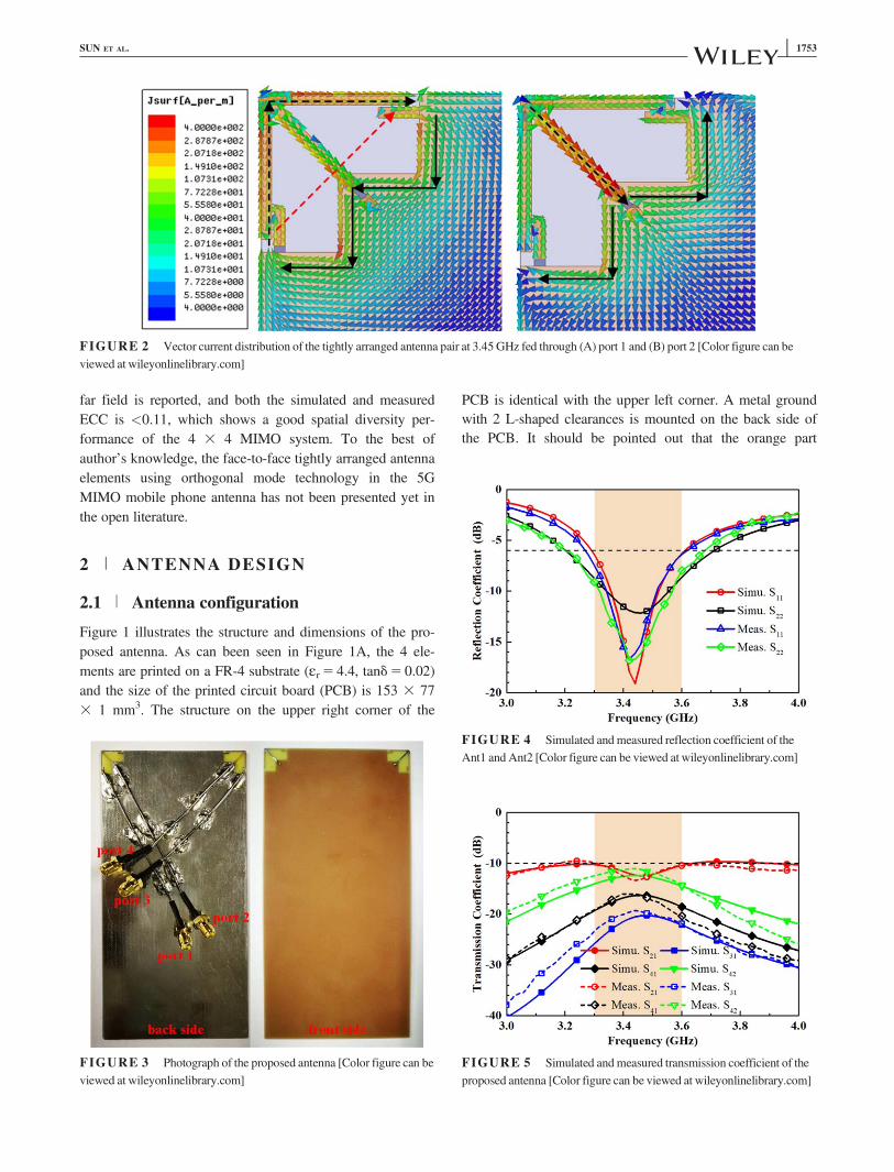
FIGURE 2 Vector current distribution of the tightly arranged antenna pair at 3.45GHz fed through (A) port 1 and (B) port 2 [Color figure can beviewed at wileyonlinelibrary.com]
FIGURE 3 Photograph of the proposed antenna [Color figure can beviewed at wileyonlinelibrary.com]
FIGURE 4 Simulated andmeasured reflection coefficient of theAnt1 and Ant2 [Color figure can be viewed at wileyonlinelibrary.com]
FIGURE 5 Simulated andmeasured transmission coefficient of theproposed antenna [Color figure can be viewed at wileyonlinelibrary.com]
SUN ET AL. | 1753
represents the metal while the gray part represents theFR4 substrate. Figure 1B shows the geometry of theback side of the antenna, 2 identical bended dipoles withgap-coupled feeding are deposited at the upper-left andupper-right corner of the PCB. When feeding throughport 1 or 3 by semi-rigid cable, the feeding stub canappropriately excite the bended strip to achieving a kg/2dipole mode, and a grounded stub is applied to keep thestructure symmetric. The orthogonal mode will be deter-iorated without the grounded stub. The front side of theantenna is shown in Figure 1C, a kg/4 arrow-shapedmonopole is fed through port 2 using semi-rigid cable
and a 1nH shunt inductance is embedded to improve theimpendence match of the monopole. The parameter ofthe structure is optimized by high-frequency structuresimulator (HFSS) 15.0 software.
2.2 | Isolation analysis
To illustrate the operating mechanism of the proposedantenna, the vector current distribution of the tightly arrangedantenna pair at 3.45 GHz fed through ports 1 and 2 isreported. When fed through port 1, as shown in Figure 2A, adipole mode is excited with the most of current distributed
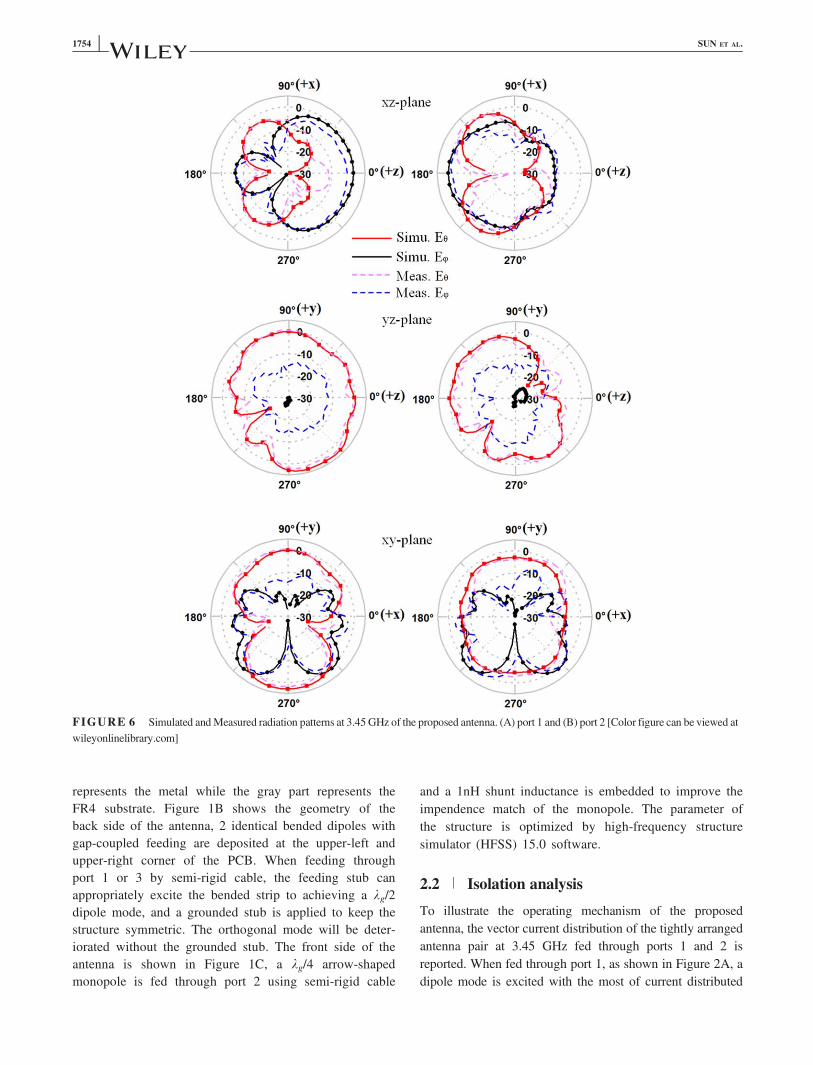
FIGURE 6 Simulated andMeasured radiation patterns at 3.45 GHz of the proposed antenna. (A) port 1 and (B) port 2 [Color figure can be viewed atwileyonlinelibrary.com]
1754 | SUN ET AL.
on the bended strip and the superimposed current directionof the dipole is 1458 which is illustrated by the red dashline. Furthermore, the black solid line in the Figure 2Ashows the ground current distribution, and the direction ofthe ground current is same. However, when fed through port2, as shown in Figure 2B, a monopole mode is excited andthe current direction is 2458 which is illustrated by the blackdash line. Furthermore, the ground current distribution inFigure 2(b) shows an orthogonal ground current mode,which denotes the direction of the ground current is inverse.In brief, the good isolation performance of the 2 tightlyarranged antenna elements is achieved due to 2 orthogonalmodes: (1) the orthogonal current mode of the 2 antenna ele-ments, so the spatial coupling will be eliminated; (2) theorthogonal ground current mode of the 2 antenna elements,so the coupling through the ground current can also be can-celed out. Therefore, a good isolation is achieved with thehelp of the orthogonal mode, which is different from6 theo-retically. And the center to center distance is only 1 mm,which is more tightly arranged than.6
3 | ANTENNA FABRICATION ANDMEASUREMENT RESULTS
In order to validate the performance of the MIMO antennasystem, a prototype of 4 3 4 MIMO mobile phone antennawas fabricated and measured. The photograph of the pro-posed MIMO antenna system is shown in Figure 3. The pro-posed MIMO antenna system has 4 ports, and four 50 Xsemi-rigid cables were used to feed 4 ports on the back sideof the proposed antenna. It should be pointed out that thesemi-rigid cables are placed away from the maximum currentregion of the ground in order not to affect the antenna’s per-formance because the ground is part of the radiator.13
3.1 | S-parameter
The simulated and measured reflection coefficient of theMIMO antenna fed through ports 1 and 2 is illustrated inFigure 4. As seen in Figure 4, the reflection coefficient of theantenna is better than 26 dB across the desired band in 3.3–3.6 GHz for both elements. As for the Ant3 and Ant4, theperformance is same as the Ant1 and Ant2 due to symmetri-cally disposed at the 2 sides of the PCB. So the results ofAnt3 and Ant4 are not shown for brevity. Figure 5 shows theisolation between the 4 ports, which is <–10 dB across thedesired band. Once again, the high port isolation is achievedin a tightly arranged antenna pair due to orthogonal mode.
3.2 | Radiation performance
The radiation patterns of the proposed antenna at 3.45 GHzwhen fed through ports 1 and 2 are shown in Figure 6. Andthe simulated and measured efficiency is reported in Figure7. The difference between the simulated and measured effi-ciency is due to the fabrication error and the loss of thelumped inductance. The measured efficiency is 48.6%–73.2% and 52.1%–64.2% when fed through ports 1 and 2,which shows a good performance in mobile phone antenna.
3.3 | Diversity performance
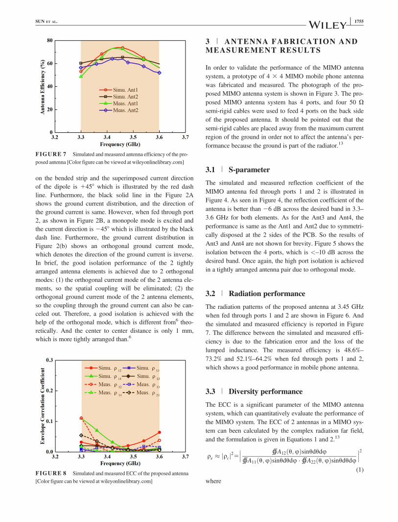
The ECC is a significant parameter of the MIMO antennasystem, which can quantitatively evaluate the performance ofthe MIMO system. The ECC of 2 antennas in a MIMO sys-tem can been calculated by the complex radiation far field,and the formulation is given in Equations 1 and 2.13
qe � jqcj25��� �A12 u;uð Þsinududu�A11 u;uð Þsinududu ��A22 u;uð Þsinududu
���2(1)
where
FIGURE 7 Simulated and measured antenna efficiency of the pro-posed antenna [Color figure can be viewed at wileyonlinelibrary.com]
FIGURE 8 Simulated and measured ECC of the proposed antenna[Color figure can be viewed at wileyonlinelibrary.com]
SUN ET AL. | 1755

Aij5Eu;i u;uð Þ � E�u;j u;uð Þ1Eu;i u;uð Þ � E�
u;j u;uð Þ (2)
The simulated and measured complex radiation far fieldof the antenna can be obtained by HFSS 15.0 and 3D mea-surement in anechoic chamber. By using Equations 1 and 2,the simulated and measured ECC can be deduced, as shownin Figure 8. The ECC of all antenna pairs are <0.11 acrossthe desired band, satisfies the standard of low ECC in mobilephone (ECC< 0.5).14 All in all, good diversity performanceis achieved within the 3.3–3.6 GHz band.
4 | CONCLUSION
In this letter, an orthogonal mode tightly arranged antennasystem operating in the 3.5-GHz band (3.3–3.6 GHz) for 5GMIMO mobile device has been studied. The 4-antenna sys-tem is composed of 2 face-to-face tightly arranged pairs,each pair includes an arrow-shaped monopole and a bendeddipole. Small mutual coupling is obtained due to the orthogo-nal current mode of each pair. As a result, good isolation anddiversity performance can be achieved with the S21< 210dB and ECC< 0.11 across the desired frequency band, andthe maximum efficiency of the Ant1 and Ant2 is 73.2% and64.2%, which shows a good performance in the mobileantenna.
ORCID
Zhijun Zhang http://orcid.org/0000-0002-8421-2419
REFERENCES[1] Poole I. (2015). LTE frequency bands and spectrum allocations.
Available at: http://www.radio-electronics.com/
[2] IMT-2020 spectrum allocations of China. Available at: http://www.miit.gov.cn/n1146285/n1146352/n3054355/n3057735/n3057748/n3057749/c5672371/content.html
[3] Al-Hadi AA, Ilvonen J, Valkonen R, Viikari V. Eight-elementantenna array for diversity and MIMO mobile terminal in LTE3500 MHz band. Microw Opt Technol Lett. 2014;56(6):1323–1327.
[4] Wong K-L, Lu J-Y. 3.6-GHz 10-antenna array for MIMO opera-tion in the smartphone. Microw Opt Technol Lett. 2015;57(7):1699–1704.
[5] Wong K-L, Lu J-Y, Chen L-Y, Li W-Y, Ban Y-L. 8-antennaand 16-antenna arrays using the quad-antenna linear array as abuilding block for the 3.5-GHz LTE MIMO operation in thesmartphone. Microw Opt Technol Lett. 2016;58(1):174–181.
[6] Wong K-L, Tsai C-Y, Lu J-Y. Two asymmetrically mirroredgap-coupled loop antennas as a compact building block for eightantenna MIMO array in the future smartphone. IEEE TransAntennas Propag. 2017;65(4):1765–1778.
[7] Wong K-L, Lin B-W, Li W-Y. Dual-band dual inverted - F/loopantennas as a compact decoupled building block for forming
eight 3.5/5.8-GHz MIMO antennas in the future smartphone.Microw Opt Technol Lett. 2017;59(11):2715–2721.
[8] Li M-Y, Ban Y-L, Xu Z-Q, et al. Eight-port orthogonally dual-polarized antenna array for 5G smartphone applications. IEEETrans Antennas Propag. 2016;64(9):3820–3830.,
[9] Li M-Y, Xu Z-Q, Ban Y-L, Sim C-Y-D, Yu Z-F. Eight-portorthogonally dual-polarised MIMO antennas using loop struc-tures for 5G smartphone. IET Microw Antennas Propag. 2017;11(12):1810–1816.
[10] Li Y, Zhang Z, Chen W, Feng Z, Iskander MF. A dual-polarization slot antenna using a compact CPW feeding struc-ture. IEEE Antennas Wireless Propag Lett. 2010;9:191–194.
[11] Li Y, Zhang Z, Zheng J, Feng Z. Compact azimuthal omnidirec-tional dual-polarization antenna using highly isolated collocatedslots. IEEE Trans Antennas Propag. 2012;60(9):4037–4045.
[12] Deng C, Li Y, Zhang Z, Feng Z. Wideband high-isolated dualpolarized patch antenna using two different balun feedings.IEEE Antennas Wireless Propag Lett. 2014;13:1617–1619.
[13] Zhang Z. Antenna Design for Mobile Devices. 2nd ed. Hoboken,NJ: Wiley; 2017.
[14] Vaughan RG, Andersen JB. Antenna diversity in mobile com-munication. IEEE Trans Vehicular Technol. 1987;36(4):149–172.
How to cite this article: Sun L, Feng H, Li Y, Zhang Z.Tightly arranged orthogonal mode antenna for 5GMIMO mobile terminal. Microw Opt Technol Lett.2018;60:1751–1756. https://doi.org/10.1002/mop.31240
Received: 14 November 2017
DOI: 10.1002/mop.31236
Compact size of thehybrid branch-linecoupler using p-typetransmission-line
Tae-Hyeon Lee1 | Ki-Cheol Yoon2
1Department of Holography 3D contents, Kwangwoon University,20 Gwangun-ro, Nowon-gu, Seoul 01897, Republic of Korea2Graduate School for Green Transportation, Korea Advanced Institute ofScience and Technology, 335 Science St., Yuseong-gu, Tae Jon 34141,Republic of Korea
CorrespondenceKi-Cheol Yoon, Graduate School for Green Transportation, KoreaAdvanced Institute of Science and Technology, 335 Science St.,Yuseong-gu, Tae Jon 34141, Republic of Korea.Email: [email protected]
1756 | LEE AND YOON