tightly coupled accelerators architecture for low-latency
TRANSCRIPT

Tightly Coupled Accelerators Architecture forLow-latency Inter-node Communication between
Accelerators
Toshihiro HanawaInformation Technology Center, The University of Tokyo, Japan
Yuetsu Kodama Taisuke Boku Mitsuhisa SatoCenter for Computational Sciences, University of Tsukuba, Japan
I. INTRODUCTION
In recent years, heterogenious clusters using acceleratorsare widely used for high performance computing system. Insuch clusters, the inter-node communication among accel-erators requires several memory copies via CPU memory,and the communication latency causes severe performancedegradation. To address this problem, we propose TightlyCoupled Accelerators (TCA) architecture, which is capable ofreducing the communication latency between accelerators overdifferent nodes. The TCA architecture communicates directlyvia the PCIe protocol, which allows it to eliminate protocoloverhead, such as that associated with InfiniBand and MPI, aswell as the memory copy overhead.
II. HA-PACS SYSTEM
HA-PACS (Highly Accelerated Parallel Advanced sys-tem for Computational Sciences) is the 8th generation ofPACS/PAX series supercomputer in Center for ComputationalSciences, University of Tsukuba. HA-PACS system consists oftwo parts as follows:
• HA-PACS base cluster is operated for the develop-ment and product-run on advanced scientific computa-tions since Feb. 2012 with 802 TFlops of peak perfor-mance. Each node is equipped with two Intel Xeon E5(SandyBridge-EP) CPUs, four NVIDIA M2090 GPUs,and dual port of InfiniBand QDR.
• HA-PACS/TCA is an extension of the base cluster,and operation has started on Oct. 2013 with 364TFlops of peak performance. Each node is equippedwith two Intel Xeon E5 v2 (IvyBridge-EP) CPUs, fourNVIDIA K20X GPUs, and each one has not onlyInfiniBand HCA but also TCA communication board(PEACH2 board) as the proprietary interconnect forGPU in order to realize GPU-to-GPU direct commu-nication over the nodes.
The TCA architecture is based on the concept of using thePCIe link as the communication network link between GPUson communication nodes rather than simply using the PCIelink and intra-node I/O interface.
Figure 1 shows a block diagram of the communication inHA-PACS/TCA. This configuration is similar to that of the
HA-PACS base cluster, with the exception of the PEACH2board. Whereas accessing the GPU memory from the otherdevices is normally prohibited, a technology called GPUDirectSupport for RDMA [1] allows direct memory access throughthe PCIe address space under a CUDA 5.0 [2] or aboveenvironment with a Kepler-class GPU [3], and we realizeTCA communication using this mechanism. In practice, sincethe direct access over QPI between sockets degrades theperformance significantly on Intel E5 CPUs, we assume thatPEACH2 only accesses GPU0 and GPU1 in Figure 1. PEACH2can transfer not only GPU memory but also host memoryseamlessly since PEACH2 relies on the PCIe protocol.
III. PEACH2 CHIP AND BOARD
HA-PACS/TCA is constructed by using the interface boardwith PCIe, which employs an FPGA chip referred to as the PCIExpress Adaptive Communication Hub version 2 (PEACH2)chip. The PEACH2 chip has four PCIe Gen2 x8 ports. Oneis dedicated to the connection to the host CPU in order tobe treated as the ordinary PCIe device. Another two ports areused to configure the ring topology. A remaining port is used tocombine two rings by connecting to the other PEACH2 chipson the neighboring nodes.
PEACH2 provides two types of communication: PIO andDMA. PIO communication is useful for short message trans-fers, and the CPU can only perform the store operation toremote nodes with minimum low latency. A DMA controllerwith four channels is also embedded. The DMA controllerprovides a chaining DMA function, which allows to transfermultiple data segments automatically by hardwired logic ac-cording to the chained DMA descriptors. The DMA controlleralso permits a block-stride transfer which can be specified witha single descriptor.
IV. BASIC PERFORMANCE EVALUATION
We evaluate the basic performance of TCA communicationusing HA-PACS/TCA. We develop two device drivers: thePEACH2 driver for controlling the PEACH2 board and theP2P driver for enabling GPUDirect Support for RDMA. Wealso evaluate the performance using a CUDA-aware MPI,MVAPICH2-GDR 2.0b for comparison. The detailed environ-ment is summarized in the poster draft, and we use up to 16nodes as a TCA sub-cluster for this evaluation.
Infin
iBan
d N
etw
ork
QPI
PCIe
InfiniBand
G2
x16
G2
x16
G2
x16
G2
x16
G2 x8 G3 x8
GPU0
CPU0 CPU1
GPU1 GPU2 GPU3
PEACH2
QPI
PCIe
InfiniBand
G2
x16
G2
x16
G2
x16
G2
x16
G2 x8 G3 x8
GPU0
CPU0 CPU1
GPU1 GPU2 GPU3
PEACH2
G2
x 8
G2
x8G
2 x
8
G2 x8PEACH2
PEACH2 G2 x8
Fig. 1. Block Diagram of the Computation Nodein HA-PACS/TCA
0
1
2
3
8 32 128 512
CPU MV2-CPUGPUMV2-GPUMV2GDR-GPU
0
5
10
15
20
25
8 128 2048
Late
ncy(
usec
)
Size (Bytes)
0
500
1000
1500
2000
2500
3000
3500
4000
64 128 256 512 1024
Ban
dwid
th (M
B/s
)
N
N*N block (TCA) N block, N*N stride (TCA) N stride (TCA) pack/unpack (TCA) N*N block (MV2) N block, N*N stride (MV2) N stride (MV2) N*N block (MV2GDR) N block, N*N stride (MV2GDR) N stride (MV2GDR)
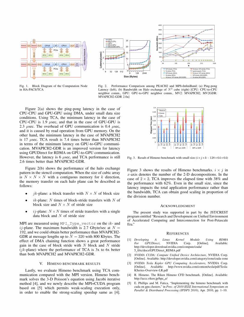
Fig. 2. Performance Comparison among PEACH2 and MPI+InfiniBand; (a) Ping-pongLatency (left), (b) Bandwidth on Halo exchange of N3 cube (right) [CPU: CPU-to-CPUneighbor comm., GPU: GPU-to-GPU neighbor comm., MV2: MVAPICH2, MV2GDR:MVAPICH2-GDR 2.0a]
Figure 2(a) shows the ping-pong latency in the case ofCPU-CPU and GPU-GPU using DMA, under small data sizeconditions. Using TCA, the minimum latency in the case ofCPU-CPU is 1.9 µsec, and that in the case of GPU-GPU is2.3 µsec. The overhead of GPU communication is 0.4 µsec,and it is caused by read operation from GPU memory. On theother hand, the minimum latency in the case of MVAPICH2is 17 µsec. TCA result is 7.4 times better than MVAPICH2in terms of the minimum latency on GPU-to-GPU communi-cation. MVAPICH2-GDR is an improved version for latencyusing GPUDirect for RDMA on GPU-to-GPU communication.However, the latency is 6 µsec, and TCA performance is still2.6 times better than MVAPICH2-GDR.
Figure 2(b) shows the performance of the halo exchangepattern in the stencil computation. When the size of cubic arrayis N × N × N with a contiguous memory for k direction,the memory transfer on each halo plane can be described asfollows:
• jk-plane: a block transfer with N ×N of block size
• ik-plane: N times of block-stride transfers with N ofblock size and N ×N of stride size
• ij-plane: N×N times of stride transfers with a singledata block and N of stride size
MPI are measured using MPI_Type_vector on the ik- andij-plane. The maximum bandwidth is 2.7 Gbyte/sec at N =192, and we could obtain better performance than MVAPICH2-GDR at message lengths up to N = 320 with 800 Kbytes. Theeffect of DMA chaining function shows a great performancegain in the case of block stride with N block and N stride(jk-plane) where the performance of TCA is 3x to 6x betterthan both MVAPICH2 and MVAPICH2-GDR.
V. HIMENO BENCHMARK RESULTS
Lastly, we evaluate Himeno benchmark using TCA com-munication compared with the MPI version. Himeno bench-mark solves the 3-D Poisson’s equation using Jacobi iterativemethod [4], and we newly describe the MPI+CUDA programbased on [5] which permits weak-scaling execution only,in order to enable the strong-scaling speedup same as [4].
0
0.05
0.1
0.15
0.2
0.25
0.3
0.35
0.4
2x1
1x2
4x1
2x2
1x4
2x1
1x2
4x1
2x2
1x4
2x1
1x2
4x1
2x2
1x4
TCA MPI w/o GDR MPI w GDR
Elap
sed
Tim
e (s
ec)
Reduce Comm Calc
Fig. 3. Result of Himeno benchmark with small size (i×j×k : 128×64×64)
Figure 3 shows the results of Himeno benchmarks. i × j inx-axis denotes the number of the 2-D decompositions. In thecase of 2× 2, TCA improves the elapsed time with 38% andthe performance with 62%. Even in the small size, since thelatency impacts the total application performance rather thanthe bandwidth, TCA can obtain good scaling in proportion ofthe division number.
ACKNOWLEDGMENT
The present study was supported in part by the JST/CRESTprogram entitled “Research and Development on Unified Environmentof Accelerated Computing and Interconnection for Post-PetascaleEra.”
REFERENCES
[1] Developing A Linux Kernel Module Using RDMAFor GPUDirect, NVIDIA Corp. [Online]. Available:http://developer.download.nvidia.com/compute/cuda/5 0/rc/docs/GPUDirect RDMA.pdf
[2] NVIDIA CUDA: Compute Unified Device Architecture, NVIDIA Corp.[Online]. Available: http://developer.nvidia.com/category/zone/cuda-zone
[3] NVIDIA Tesla Kepler GPU Computing Accelerators, NVIDIA Corp.[Online]. Available: http://www.nvidia.com/content/tesla/pdf/Tesla-KSeries-Overview-LR.pdf
[4] R. Himeno. The Riken Himeno CFD benchmark. [Online]. Available:http://accc.riken.jp/hpc e/
[5] E. Phillips and M. Fatica, “Implementing the himeno benchmark withcuda on gpu clusters,” in Proc. of 2010 IEEE International Symposium onParallel & Distributed Processing (IPDPS 2010), Apr. 2010, pp. 1–10.