timber – concrete composite elements with various ... · pdf file939 wood research 60...
TRANSCRIPT

939
WOOD RESEARCH 60 (6): 2015 939-952
TIMBER – CONCRETE COMPOSITE ELEMENTS WITH
VARIOUS COMPOSITE CONNECTIONS
PART 3: ADHESIVE CONNECTION
Ján KanóczTechnical University of Košice, Faculty of Art
Košice, Slovak Republic
Viktória BajzecerováTechnical University of Košice, Faculty of Civil Engineering
Košice, Slovak Republic
(Received September 2015)
ABSTRACT
In the presented paper theoretical and experimental investigations of two types of timber-concrete composite structural elements with lightweight concrete is described. For the first type of composite beams vertically laminated timber, for the second type cross-laminated timber was used. Composite connection between the timber and concrete special adhesive for wet concrete was applied. To determine the load – displacement characteristics four point short and long term bending tests were carried out on the both type of composite beams. In middle span of the beams vertical displacements were gauged and also deformations in the beam s middle cross section were detected. To determine the shear parameters of the composite connection, short term shear tests were performed. The received results of bending tests with theoretical models for short and long term loading were compared respectively. In theoretical model the composite structure of cross-laminated timber was taken into account.
KEYWORDS: Timber-concrete composite, adhesive connection, vertically laminated timber, cross-laminated timber, light-weight concrete, short term bending test, long term behavior.
INTRODUCTION
This paper is the third part of the series of papers describing theoretical analysis and experimental investigations of various timber-concrete composite slab systems in the framework of the series of research projects oriented to their different composite connection under short and long term loading.
940
WOOD RESEARCH
At the first phase of the project, timber-concrete composite beams with screwed composite connection were investigated (Kanócz et al. 2013). At the next phase, the composite deck system consisting from the vertically laminated nailed timber-concrete with grooved connection was examined (Kanócz et al. 2014). The main purpose of the project was to determine several structural characteristics of different timber-concrete composite systems and based on the experimental tests determine suitable theoretical calculation models for investigated composite members under the short and long term static loading.
This paper describes real response and theoretical modeling of composite beams consisting from vertically laminated and cross-laminated timber decks with lightweight concrete layer on the top. For composite connection of timber and concrete special adhesive bounding wet concrete and timber was applied. For that purpose special adhesives SikaDur T35 LVP were developed. Advantage of gluing the wet concrete is not only in high efficiency of shear connection, but also in the savings reinforcement in the concrete section, which in the prefabricated concrete slab is necessary because of their handling.
To produce timber-concrete composite member also lightweight concrete is possible to use. This type of composite member has several advantages, as a lower construction weight and positive thermal insulation and acoustic properties. Lightweight concrete has a minor displacement from creep, but increased displacement from shrinkage, this phenomenon has significant influence to the long term displacement of timber – lightweight concrete composite elements (Jorge et al. 2010a).
The cross laminated timber (CLT) consists of at least three layers of timber lamellas; the alignment of lamellas in each layer is alternated at 90°. Mostly the lamellas are glued to each other, but also mechanical fasteners are usable to connect them together (Kuklík 2014). Structural members produced from CLT boards are the solid panels applicable for bearing structures loadable perpendicular and parallel to their plane respectively (as a slab or wall structure). To connect concrete to CLT to create timber – concrete composite element several mechanical methods are available (Jorge et al. 2010b, Jacquier et al. 2012), but also gluing is suitable (Negrão et al. 2010a, b; Brunner and Schnüriger 2005).
MATERIAL AND METHODS
Characteristic of the specimens and materialSpan of the beam 4.5 m or 6.0 m resulted from the aim to apply investigated timber-concrete
composite beams as building slabs. For the first type of composite beams "TC1_4.5" and "TC1_6.0" glued vertically laminated timber (VLT) with depth 80.0 and 120.0 mm was used respectively. The thickness of the light-weight concrete layer was 50.0 mm. For the second type of composite beams signed as "TC2" cross-laminated timber (CLT) slab with the same dimensions as VLT was used. The width of the slabs was 600.0 mm. The depth of light-weight concrete slab of beams "TC2_4.5" and "TC2_6,0" was 50.0 and 60.0 mm, respectively. In the Fig. 1 and Tab. 1 geometrical and material parameters of beams are summarized. Three beam specimens of each type were prepared (Fig. 2).

941
Vol. 60 (6): 2015
Fig. 1: Beam geometry (1 - light-weight concrete, 2- adhesive Sikadur T35 LVP, 3- vertically laminated timber, 4- cross laminated timber).
Fig. 2: Preparing of specimens.
Tab. 1: Parameters of beams.
Beam type TC1_4.5 TC1_6.0 TC2_4.5 TC2_6.0Length (m) 4.5 6.0 4.5 6.0
Theoretical length (m) 4.4 5.8 4.4 5.8
Concrete partDepth (mm) 50.0 50.0 50.0 60.0
Strength class LC20/22 LC20/22 LC20/22 LC20/22
Timber part
Type of material VLT VLT CLT CLTDepth (mm) 80.0 120.0 80.0 120.0
Layers - - 30-20-30 40-40-40Strength class GL24 GL24 C24 C24
The concrete layer was produced using lightweight aggregates - Ceramic Expanded Clay Spheres named “Liapor”. The Light-weight Liapor Concrete disposes with positive mechanical and physical building properties. Material parameters of used concrete were determined according to the relevant standards. See overview in Tab.2.
Tab. 2: Average stress and deformation parameters of the concrete.
Beam type TC1 TC2 Cylinder compressive strength 25.6 19.3 MPaCube compressive strength 29.1 24.1 MPaModulus of elasticity 17.7 20.8 GPaDensity 1792.0 1827.0 kg.m-3
Tab. 3: Stress and deformation parameters of the timber part TC1.Bending strength 54.79 MPaModulus of elasticity 13 930 MPaTensile strength 32.87 MPaDensity 425 kg.m-3
Strength class of the VLT was considered as the strength of glued laminated timber GL24. Material parameters were experimentally evaluated according to (EN 408, 2013). See overview in Tab. 3. Strength class of the timber for producing the CLT was C24. According to (Harris et al. 2013), characteristic bending strength of CLT panels can be based either the tensile strength

942
WOOD RESEARCH
of the base material (planks), or the characteristic bending strength of glued laminated timber of the appropriate strength class according to:
fm,CLT, k = kl . fm,GLT, k (1)
where: fm,CLT,k - characteristic bending strength of the cross laminated timber, fm,GLT,k - characteristic bending strength of the glued laminated timber, kl - system strength factor,
The system strength factor kl takes into account the parallel effect of interacting components and can be assumed as 1.1 (Harris et al. 2013). Other expected strength and deformation characteristics were based on the characteristics of glued laminated timber GL24 (Tab. 4).
Tab. 4: Stress and deformation parameters of the timber part TC2.
Bending strength 26.4 MPaTensile strength 16.5 MPaShear strength 2.7 MPa
Rolling shear strength 1.25 MPaModulus of elasticity paralell to the grain 11 600.0 MPa
Modulus of elasticity perpendicular to the grain 390.0 MPaShear modulus paralell to the grain 720.0 MPa
Shear modulus perpendicula to the grain 72.0 MPaDensity 420.0 kg.m-3
The composite action between the timber and concrete part was provided by adhesive Sikadur T35 LVP. It is a 2-component epoxy resin adhesive not yet commercially available. Advantage of this adhesive material is moisture tolerant and thereby possibility bonding wet concrete with timber. It is high-early-strength developing and no shrinkage hardening adhesive. Time of application in 20°C of environment is 90 minutes after mixture components of adhesive (Brunner et al. 2007).
Preparing of specimensInvestigation indicates significant influence of concrete shrinkage on timber-concrete
composite beams deflection (Kanócz and Bajzecerová 2012), hence precamber of timber beams during concrete hardening was applied. The precamber of beams with span 4.5 and 6.0 m was 10.0 and 15.0 mm, respectively. Surface of the timber beam was cleaned from dust and dirt. Adhesive was continuously spread on the top of the timber slabs with coverage 1.1 kg.m-2. To avoid crowding of the adhesive was necessary pouring the wet concrete into the adhesive from relatively low height and carefully (Brunner and Schnüriger 2005). Concrete layer was applied till 60 min after adhesive mixture. As resulted from precalculation model, whole depth of concrete section within simple bending will be compressed and therefore no reinforcement in concrete part was used. Concrete curing took about 3 days. Three specimen of each type and length was prepared, 12 beams totally.
Connection parametersShear strength of glued connection between timber and concrete was evaluated according to
(EN 392, 1998). Preparing of 6 pieces of shear test specimens was carried out within the casting

943
Vol. 60 (6): 2015
of beams “TC1” using same materials. The set up of the shear tests according to Fig. 3 was designed to prevent the eccentric load application of the glued gap. The failure modes of all tested shear specimens was shear failure of concrete part and due to small eccentric load partially shear collapse of timber fiber. Measured values of shear strength reached 4.75 to 5.75 MPa, average value was 5.27 MPa (Tab. 5). On both sides of the specimens the relative slip between timber and concrete were measured by digital gauges.
Fig. 3: Setup of the shear tests, load–slip diagram and failure mode.
Fig. 4: Experimental test setup.
Tab. 5: Results of the shear strength test.
Specimen 01 02 03 04 05 06Shear strength (MPa) 4.84 5.44 4.75 5.75 5.29 5.53
Beam bending test under short term loadingFour points bending test with short term static load was carried out (Fig. 4). Two beam
specimens of each two span type “TC1” were subjected to short term loading, the rest of two beams were subjected to long term loading. The short term loading schedule for this beam type was suggested with four unloading loop up to 40 % of estimated failure load level. Above this level the loading process was increasing continuously. In the second phase of experiment, all six specimens of type “TC2” were subjected to short term loading with only one unloading loop on the 40 % of estimated failure load level.
Using acquisition device Spider 8 middle deflection and deflections at the points of loads application were gauged. To discover the character of deformation, horizontal displacement on the middle cross-section of composite beam was measured in four levels on the beam depth. Horizontal gauges were placed on the top and bottom fiber of concrete and timber part on the both sides of middle cross-section. In case of beams type “TC2”, horizontal slip between upper and lower layer of CLT was measured. Initial deflection values in the middle of span are summarized in Tab. 6.

944
WOOD RESEARCH
Tab. 6: Measured value of initial deflection.
Beam type TC1_4.5 TC1_6.0 TC2_4.5 TC2_6.0Specimen 1 2 3 1 2 3 1 2 3 1 2 3
p (mm) 10.0 15.0 10.0 15.0sh (mm) 8.5 4.0 5.5 1.0 0.0 3.0 9.5 12.0 9.0 - 6.8 5.8sw (mm) 12.0 12.0 10.0 - 8.0 13.0 13.0 15.0 12.5 6.5 14.0 13.4
p – precamber, sh - initial def lection including concrete shrinkage before removing temporary support, sw - initial def lection after removing temporary support including self weight.
Beam bending test under long term loadingSince august 2013 two beams type “TC1” with span 4.5 and 6.0 m are subjected to four
point bending test with long term constant static load according to the Fig. 5. The load history is summarized in Tab. 7. Value of the long term load resulted from the expected quasi permanent load on building slabs. Using acquisition device Spider 8 middle span deflection is continuously gauged. Horizontal displacements on the top and bottom fiber of concrete and timber part of middle cross-section are periodically measured. The experiment is carried out inside, moreover humidity and temperature of the internal environment and also the timber moisture content are periodically measured.
Tab. 7: History of load application measured from the concrete casting.Beam TC1_4.5_3 TC1_6.0_3
Beginning of drying shrinkage 3 3 daysRemoval of temporary support 69 75 days
Application of permanent load “F” 82 82 daysPermanent load “F” 3.0 4.0 kN
Fig. 5: Experimental test setup and environmental condition within the long term test.
Calculation model for bonded multi-layer compositesIn the case of timber – concrete beams with adhesive composite connection the composite
action may be assumed ideally rigid. To determine load resistance of beams "TC1" is possible according to the analytical calculation model described in (Kanócz at al. 2014), which is useable for ideal rigid connection. The mentioned calculation model is not suitable in case of beams 'TC2', because in laminations of CLT the layers have different grain direction (crosswise). In the layers with grain orientation perpendicular to longitudinal axis of beam the “rolling shear” effect is occurs, which cause the stiffness reduction.
To determine the resistance of CLT panels several analytical method based on beam theory is available. One method is the theory of laminated beam, respectively composite theory (Laminated Beam Theory, respectively Compost Theory) reflecting the different stiffness properties of each layer. It is quite suitable for relatively slender beams spread to the ratio L/h ≥ 30, with span L and the section height h (Blass and Fellmoser 2004, Gagnon and Pirvu 2011). In the case of a lower
945
Vol. 60 (6): 2015
ratio, it is necessary to take into account shear deformation using Tymoshenko beam theory in the form of shear factor κ (Harris et al. 2013). Another suitable analytical method applicable to CLT beams is called Shear Analogy Method (Mestek et al. 2008). The method takes account of the different modules of elasticity, and the shear modulus of each layer in the different configurations. It is applicable to any number of layers and any L/h. Shear deformation of transverse layers is taken into account in calculating process of deflection from shear. The calculating method of the effective bending stiffness of built up timber beams with semi-rigid composite action (Möhler 1956) called γ-method allows to take into account slips between the individual layers. This model is usable in the case of CLT beams when the shear f lexibility of transversal layers is considered in calculation process. (Gagnon and Pirvu 2011).
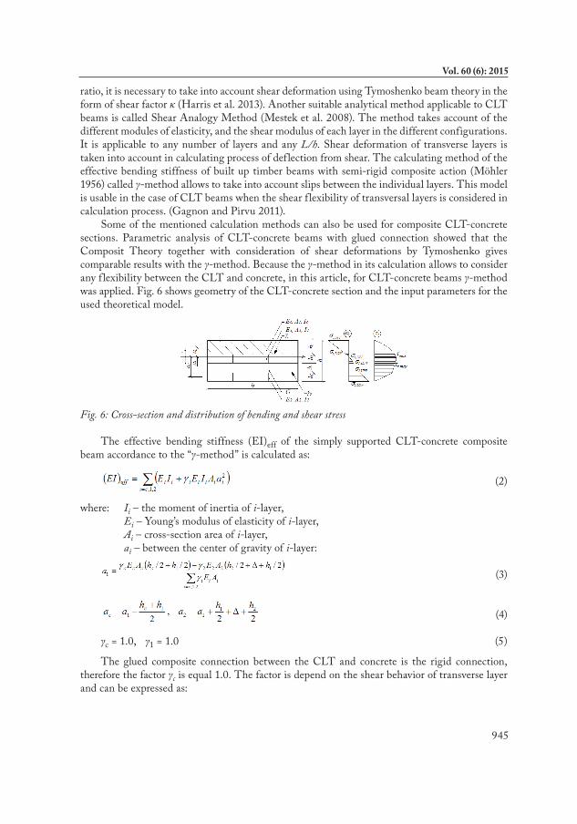
Some of the mentioned calculation methods can also be used for composite CLT-concrete sections. Parametric analysis of CLT-concrete beams with glued connection showed that the Composit Theory together with consideration of shear deformations by Tymoshenko gives comparable results with the γ-method. Because the γ-method in its calculation allows to consider any f lexibility between the CLT and concrete, in this article, for CLT-concrete beams γ-method was applied. Fig. 6 shows geometry of the CLT-concrete section and the input parameters for the used theoretical model.
Fig. 6: Cross-section and distribution of bending and shear stress
The effective bending stiffness (EI)eff of the simply supported CLT-concrete composite beam accordance to the “γ-method” is calculated as:
(2)
where: Ii – the moment of inertia of i-layer, Ei – Young’s modulus of elasticity of i-layer, Ai – cross-section area of i-layer, ai – between the center of gravity of i-layer:
(3)
(4)
γc = 1.0, γ1 = 1.0 (5)
The glued composite connection between the CLT and concrete is the rigid connection, therefore the factor γc is equal 1.0. The factor is depend on the shear behavior of transverse layer and can be expressed as:

946
WOOD RESEARCH
(6)
where: G90 – shear modulus paralell to the grain, Δ – depth of the CLT cross layer, b – with of the CLT panel.
Index „c“ refer to concrete part of composite cross-section, index „1“ refer to 1st longitudinal timber layer, index „2“ refer to 2nd longitudinal timber layer.
In the expressions (2) to (6) is necessary take into account the respective modules of elasticity of the individual layers. For the concrete layer the mean modulus of elasticity Ec,mean, for the longitudinal layers of CLT the median modulus of elasticity of wood in the direction of grains E0,mean. Contribution of the transverse layers to the bending stiffness is very low, therefore in the calculation of bending stiffness are neglected.
Normal stress distribution in the timber-concrete composite cross-section (Fig. 6) is calculated as:
where i = c, 1, 2 (7)
Normal stress value in upper (UPP) and lower (LOW) fibers of i-layer is given by:
where i = c, 1, 2 (8)
The maximum shear stresses of composite cross-section (Fig. 6) depend on the position of neutral axis. If the neutral axis is in concrete part of the cross-section, the maximum shear stress is calculated as:
(9)
If the neutral axis occurs in the first layer of cross-laminated timber, the maximum shear stress is calculated as:
(10)
The shear stress in the gap between 1st longitudinal and cross timber layer is calculated as:
(11)
The shear stress in the glued gap between concrete and timber part of the cross-section is calculated according to:
(12)
Analytical calculation model of long term behavior of the CLT-concrete composite beams can be obtained considering the viscous-elastic creep of concrete and wood, mechano-sorptive creep of wood, creep of shear connection, concrete shrinkage and strains due to thermal and relative humidity changes of environment according to (Kanócz et al. 2013).
947
Vol. 60 (6): 2015
RESULTS AND DISCUSION
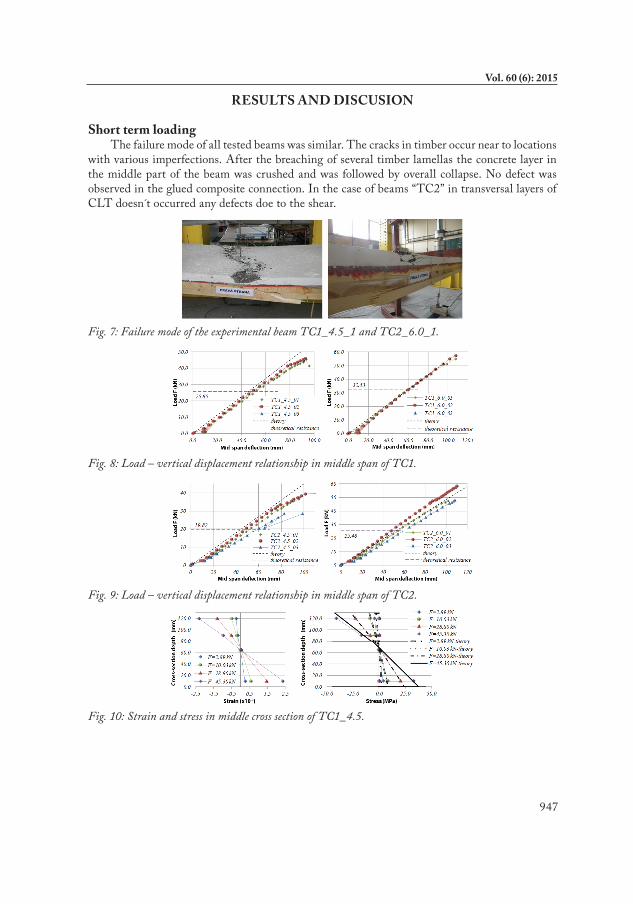
Short term loading The failure mode of all tested beams was similar. The cracks in timber occur near to locations
with various imperfections. After the breaching of several timber lamellas the concrete layer in the middle part of the beam was crushed and was followed by overall collapse. No defect was observed in the glued composite connection. In the case of beams “TC2” in transversal layers of CLT doesn´t occurred any defects doe to the shear.
Fig. 7: Failure mode of the experimental beam TC1_4.5_1 and TC2_6.0_1.
Fig. 8: Load – vertical displacement relationship in middle span of TC1.
Fig. 9: Load – vertical displacement relationship in middle span of TC2.
Fig. 10: Strain and stress in middle cross section of TC1_4.5.

948
WOOD RESEARCH
Fig. 11: Strain and stress in middle cross section of TC1_6.0.
Fig. 12: Strain and stress in middle cross section of TC2_4.5.
Fig. 13: Strain and stress in middle cross section of TC2_6.0.
The measured mid-span deflection values are presented on Figs. 8 and 9. Deflection-load relationships of all experimental beams “TC1” seem to be similar and appear equivalent stiffness (see Fig. 8). Differences between the mid span displacements of the beams “TC 2” are approximately 20 % and are bigger than differences in case of beams “TC 1” (see Fig. 9).
Tab. 8: Comparison of numerical and experimental results.
Perameter MethodBeam type / specimen
TC1_4.5 TC1_6.0 TC2_4.5 TC2_6.01 2 3 1 2 3 1 2 3 1 2 3
(EI)eff .10-12 Num. 1.72 3.82 1.38 3.43Exp. 1.49 1.57 - 3.72 3.72 - 1.17 1.22 0.93 3.2 3.7 3.0
k=δ/FNum. 1.8 1.9 2.2 2.1Exp. 2.1 2.0 - 1.9 1.9 - 2.6 2.5 3.2 2.2 1.9 2.4
FmaxNum. 25.9 32.5 19.8 25.5Exp. 46.1 46.1 - 55.0 57.3 - 37.4 40.4 28.4 47.4 58.4 49.4
Comparison of resultsThe measured and calculated normal stresses diagrams along the depth of mid span cross
section are compared on Figs. 10 to 13. The calculated values from the presented calculation

949
Vol. 60 (6): 2015
models were received. The comparison shows the quite good fitting of measured and calculated data.
In experimental tests of each beam the calculated limit load was exceed approximately by 40 %, (see Figs. 8 and 9). It can be caused by higher real strength of used materials. The comparison of results shows that the used calculation models with sufficient accuracy describes the real response of the wood-concrete beams with glued composite connection under short term loading. This confirms that from the short term point of view glued composite connection by the agent Sikadur T35 LVP is acting as a rigid connection.
Long term loading On Fig. 14 measured values of mid-span deflection of two beams from long term load during
the 2 year period are presented. The experiment is still going on, but the present results in fairly good agreement are with the simplified model shown in (Kanócz et al. 2013).
Fig. 14: Comparison of experimental and theoretical mid-span deflection in time.
CONCLUSIONS
Results of experimental tests shows, that the adhesive composite connection of the timber – concrete structural members is very effective. Comparing to mechanical fasteners, with adhesive composite connection higher bending stiffness is possible to achieve. On the other hand, the adhesive connection has increased effect to the influence of concrete shrinkage to the deflection of composite beams. Using lightweight concrete there is possibility to save part of self-weight loading and getting space to rise up the applied load.
The long time behaviors of the glued composite connection are still not investigated in detail. The above mentioned ongoing long term loading experiment of timber-concrete beams will bring us more information and the measured data will compared with results of the similar investigation presented by other authors. In present paper used simplified theoretical model seems to be applicable to receive the real response of timber-concrete composite beams with adhesive connection for short term loading and can be used in practical design process.
ACKNOWLEDGMENTS
This paper was prepared with supporting of the grant VEGA Project No. 1/0865/11. Paper is the result of the Project implementation: University Science Park TECHNICOM
for Innovation Applications Supported by Knowledge Technology, ITMS: 26220220182, supported by the Research & Development Operational Programme funded by the ERDF.
950
WOOD RESEARCH
REFERENCES
1. Blass, H., Fellmoser, P., 2004: Design of solid wood panels with cross layers. 8th World Conference on Timber Engineering, Lahti. Pp 1001-1006.
2. Brunner, M., Schnüriger, M., 2005: Holz-Beton-Elemente mit Klebeverbund, Forchungsbericht Nr. 2637-SB-01. Hochschule für Architektur, Bau und Holz, Burgdorf, Biel.
3. Brunner, M., Romer, M., Schnüriger, M., 2007: Timber-concrete-composite with an adhesive connector (wet on wet process). Material and Structures 40(1): 119-126.
4. EN 392, 1998: Glued laminated timber. Shear test of glue lines.5. EN 408, 2013: Timber structures. Test methods. Solid timber and glued laminated timber.
Determination of some physical and mechanical properties.6. Gagnon, S., Pirvu, C., 2011: CLT Handbook: Cross-laminated timber. Quebec,
FPInnovations.7. Harris, R., Ringhofer, A., Schickhofer, G., 2013: Focus solid timber solutions. – In:
European Conference on Cross Laminated Timber (CLT), Graz University of Technology.8. Jacquier, N., Girhammar, U.A., 2012: Tests on shear connections. In: Prefabricated composite
cross-laminated-timber and concrete elements. In: WCTE 2012, 11th International Conference on Timber Engineering.
9. Jorge, L., Habenbacher, J., Dujic, B., 2010a: Timber-concrete composite systems with crosslaminated timber. In: WCTE 2010, 10th International Conference on Timber Engineering.
10. Jorge, L.F., Schänzlin, J., Lopes, S.M.R., Cruz, H., Kuhlmann, U., 2010b: Time-dependent behaviour of timber lightweight concrete composite f loors. Engineering Structures 32(12): 3966-3973, ISSN 0141-0296.
11. Kanócz,J., Bajzecerová,V., Šteller, Š., 2013: Timber-concrete composite elements with various composite connections. Part 1: Screwed connection. Wood Research 58(4): 555-570.
12. Kanócz,J., Bajzecerová,V., Šteller, Š., 2014: Timber-concrete composite elements with various composite connections. Part 2: Grooved connection. Wood Research 59(4): 627-638.
13. Kanócz,J., Bajzecerová,V., 2012: Influence of rheological behaviors to load-carrying capacity of timber-concrete composite beams under long term. Procedia Engineering 40: 20-25.
14. Kuklík, P., Velebil, L., Nechanický, P., 2014: Mechanically jointed CLT panels for wall, f loor and timber-concrete composite structures. In: WCTE 2014, 12th International Conference on Timber Engineering.
15. Mestek, P., Kreuzinger, H., Winter, S., 2008: Design of cross laminated timber (CLT). 10th
World Conference on Timber Engineering, Miyazaki, Japan.16. Möhler, K., 1956: Über das Tragverhalten von Biegeträgern und Druckstäben
mit zusammengesetzem Querschnitt und nachgiebigen Verbindungsmitteln. Habilitationsschrift, Karlsruhe.
17. Negrão, J., Leitão de Oliveira, C., Maia de Oliveira, F., Cachim, P., 2010a: Glued composite timber-concrete beams. In: Interlayer connection specimen tests. Journal of Structural Engineering 136(10): 1236-1245.
18. Negrão, J., Maia de Oliveira, F., Leitão de Oliveira, C., Cachim, P., 2010b: Glued composite timber-concrete beams. II: Analysis and tests of beam specimens. Journal of Structural Engineering 136(10): 1246-1254.

951
Vol. 60 (6): 2015
Ján Kanócz*Technical University of Košice
Faculty of ArtLetná 9
Sk-042 00 KošiceSlovak Republic
Corresponding author: [email protected]
Viktória BajzecerováTechnical University of KošiceFaculty of Civil Engineering
Vysokoškolská 4Sk-042 00 KošiceSlovak Republic

952
WOOD RESEARCH