timber pole safety by design
TRANSCRIPT

Transportation Research Record 1065 1
Timber Pole Safety by Design
DON L. IVEY and JAMES R. MORGAN
ABSTRACT
A breakaway design for the modification of timber utility poles that will radically increase the safety of passengers in impacting vehicles has been developed and comprehensively tested. This design is called the Hawkins breakaway system (HBS) • The system not only accomplishes the goal of increasing safety but exhibits characteristics of significant advantage to a utility company. A statement of safety philosophy applicable to the evaluation of roadside structures has been prepared. It can be used as the basis for the evaluation of any proposed safety improvement relative to roadside geometry and structures. It was used here to develop compliance tests for breakaway utility poles and to evaluate the results of those tests. Analysis of the literature relative to the cost-effectiveness of breakaway utility poles reveals that there will be a positive societal benefit associated with carefully selected applications.
Timber utility poles carrying power and communication transmission lines on highway rights-of-way are an anachronism. They represent a critical discontinuity in the "forgiving roadside," a concept developed and accepted in the 1960s and that state DOTs have striven to make a reality ever since. Timber utility poles are different from structures such as signs, luminaire supports, and hydraulic structures. They are owned by someone other than the highway or transportation entity responsible for the roadway. These transportation agencies have been hesitant, except under reconstruction conditions, to require a utility company to move or modify its facilities. There has been no consensus as to precisely who should be responsible for the influence on safety of timber utility poles within the highway right-of-way. In the past many utility companies appear to have assumed that highway safety was the responsibility of highway agencies. Although at times that attitude may have been justified, it may no longer be in the best interest of pole owners. Devices now exist that provide cost-effective safety treatments for exposed structures without significant detrimental influence on the primary objective (i.e., the transmission of power and information).
Until 1982 Southwest Research Institute (SwRI) performed most of the work in applying breakaway technology to timber utility poles. Beginning with a 1973 study by Wolfe and Michie (!_) various arrangements of holes, grooves, and saw cuts were used to weaken the pole at its base so the pole would fall more easily during a vehicle impact. Another weakened zone was introduced near the top of the pole so that under impact conditions the middle section of the pole would break away leaving the top portion still connected to the utility lines. The best of these designs was called RETROFIX.
It appears that both the utility industry and the FHWA decided that RETROFIX should not be implemented. This was primarily because the pole was significantly weakened in its capacity to withstand environmental loads. To try to overcome the strength problem and other concerns of industry, the FHWA contracted with SwRI to develop a slip base breakaway design. The slip base designed by Bronstad for utility poles and
Safety Division, Texas Transportation Institute, The Texas A&M University System, College Station, Tex. 77843.
used by Labra et al. (2) appears to be an adaptation of the triangular, three-bolt, multidirectional slip base developed by Edwards (3). It represents the first application of con~entional slip base technology to a timber utility pole.
The primary objective of this work was to build on the conventional slip base technology to develop an implementable design. In addition to production of a more effective breakaway shear connection at ground level, this required overcoming the problems of pole detachment, conductor failure and entanglement, and the falling pole. This objective has been realized. A combination of a slip base lower connection and a progressively deforming upper connection has been subjected to five compliance tests. This combination of lower and upper connections has been named the Hawkins breakaway system (HBS) after D.L. Hawkins, who may have been the first to suggest slip bases on roadside structures (_!). These tests have been compared on an acceleration, velocity change, and probability of injury basis to calculated values for unmodified poles. They also have been compared with a statistically derived probability of injury estimate for unmodified poles developed by Mak and Mason (5). The compliance tests conducted meet the criteria defined by NCHRP Report 230 (~).
The test selection was made using a new statement of safety philosophy that is described in detail in the full report <2>· These comparisons will be detailed in a later section of this paper, but the net result may be stated as follows: In collisions at speeds of from 20 to 60 mph using automobiles of from 1,800 to 4,300 lb gross vehicle weight (GVW), the average probability of severe in)ury [abbreviated injury scale (AIS) > 3] has been reduced by 91 percent. In collisions at speeds of from 40 to 60 mph, the probability of severe injury has been reduced by 97 percent. These reductions are far in excess of what most researchers considered probable. Zegeer and Cynecki (8) use example values of 30 and 60 percent reduction- in injury and fatal accidents in their benefit-cost studies for FHWA. Although the 60 percent value may not be unreasonable if AIS injuries of 1 are considered, it appears that injuries would be heavily biased to the minor and moderate injury levels (AIS levels 1 and 2). Thus Zegeer 's and Cynecki 's use of the 60 percent overall reduction in injury and total accidents may still be too low when accident costs for the break-

2
away design are calculated, and the HBS would be cost-effective in a wider spectrum of conditions than was predicted.
The HBS design consists of a slip base similar to those developed by TT! 17 to 20 years ago for use on sign and luminaire supports <il : an upper hinge mechanism and structural support cables (overhead guys) (Figure 1). The slip base connection is unique in that it is a six-bolt connection to reduce weight.
FIGURE 1 Modified utility pole installation.
These mechanisms are activated on impact and are intended to reduce the inertial effects of the pole on the errant vehicle while minimizing the impact on utility service. Typical performance of the HBS is shown in Figure 2. The slip base is designed to withstand the overturning moments imposed by inservice wind loads and, at the same time, slip when subjected to the forces of a collision.
A lower shear plane is created through installation of a slip base at an elevation of 3 in. above grade. The elevation of the slip base is intended to avoid snagging on the underside of an errant vehicle. This shear plane consists of two 5/8-in.-thick plates separated by a 26-gauge keeper plate (intended to maintain a bolt circle diameter of 15 1/2 in.) and by washers 2 1/2 in. in diameter by 1/8 in. The base plates are connected to each other by six 1-in.diameter high-strength bolts with washers 2 1/2 in. by 1/4 in. These bolts are torqued to 200 ft-lb. Connection of the wooden utility pole to the slip base is through a st!;!el pipe or tubing (Figure 3). These tubes are nominally 12 in. in diameter and 30 in. long and are welded to the base plates. In addition, the base plates are braced by 5/8-in.-thick stiffeners that are welded to both the base plate and the steel tube.
The upper hinge mechanism is sized to adequately
Transportation Research Record 1065
transmit service loads while hinging during a collision to allow the bottom segment of the pole to rotate out of the way. This connection consists of two four-part pole bands installed above and below a saw cut through the pole and four straps connecting the two pole bands. The pole bands and straps are further secured to the pole by means of 1-in.-diameter through bolts as shown in Figure 4. At the bottom pole band, the bolts pass through the ends of the straps. At the lower end, the bolt holes are separated from four 1/2-in.-long slots by a 3/16-in. section of steel. Initial bending resistance is provided by the strength of this 3/16-in. margin. When the margin is punched out, resistance is offered by friction between the straps and bolts and by bending of the straps. When significant rotation has occurred, the bolts bear on the end of the slot, thereby providing the required ultimate bending strength. This upper connection reduces the effective inertia of the pole and m1n1m1zes the effect of any variation in hardware attached to the upper portion of the pole during a collision. The entire HBS system is designed to achieve the industry standard safety factor of four before ultimate failure. This design has been verified by static tests.
A series of tests was conducted to verify the performance of the HBS. In selecting the test matrix, it was necessary to define and adhere to a specific safety criterion. That criterion is:
A new structural design for a highway auxiliary structure should be strongly considered for implementation if
1. The new design results in significant improvement in safety for the majority of drivers and passengers,
2. The new design does not result in a significant deterioration in safety for any group of vehicle occupants, and
3. ~hP.rP ~rP. no other proven designs of equal or better cost-effectiveness that produce a safer condition for a larger spectrum of vehicle occupants.
Although this safety criterion may appear to be self-evident, its acceptance could allow use of structures that vastly improve the safety of the traveling public while not meeting all requirements of NCHRP Report 230 <§.l or Transportation Research Circular 191 (~). Although the HBS does meet the requirements of NCHRP Report 230 and Transportation Research Circular 191, it will be demonstrated here how the alternate safety criterion can be applied.
The specific case under consideration is that of utility poles. The questions derived from the alternate safety criterion are:
1. Will breakaway poles result in a significant improvement in safety for the majority of drivers and passengers?
2. Will the design result in a significant deterioration in safety for any group of vehicle occupants (in this case, for drivers of very small cars)?
3. Are there other proven structural designs of equal or better cost-effectiveness that produce a safer condition for a larger spectrum of vehicle occupants?
It will be shown in later sections that breakaway utility poles implemented selectively, as suggested by both Mak and Mason (_?_) and Zegeer and Cynecki (!!_), will satisfy the proposed criterion. To prove that compliance, it was necessary to test proposed designs to determine if Element l was achieved. The approach to that was to select a series of compliance

Slip base activities
Upper connection is fully activated
Lower part of pole rotates above vehicle
Impact
Vehicle drives under pale
Upper connection starts to bend
Lower part of pole starts to rotate
FIGURE 2 Function of Hawkins breakaway system during a vehicle collision.
!5/8"R
4 - I" DIA HOLES FOR DRAINING S INTRODUCTION OF BONDING MATERIAL
1118" DIA A 32!5 BOLTS , WITH 2 112" • 114" WASHERS
--fl--_.:~k----111--( ... , I (SEE DETAIL/
LOCK WASHER
4!5"
114"WASHER
UPPER BASE PLATE ._,.=.,._ __ 26 GAGE KUP£R PLATE
LOWER BASE PLATE
l/4°WASHER
SECTION A-A
I" HOl.E FOR WOOD TESTING
t--- ---10 112·
BOLT CONNECTION DETAIL CYLINDRICAL TUBE SUP BASE
FIGURE 3 Lower connection-slip base.
DRILL AND TAP AS R£0UIRED FOR STEEL POLE STEPS
2 '-6
!518"

4
1" Die. All Thread
Pole Bend Joslyn J25969.2 or Equlva lent
Steel Straps
Transportation Research Record 1065
112" Thick Steel
112" Die . Hole
1 1116"
15116" Dia.
FIGURE 4 Upper connection-pole band with modified slotted straps.
crash tests that would encompass a clear majority of impact conditions.
The tests selected are given in Table 1. The primary purpose of each test is shown in the final column. The actual test conditions achieved are shown in parentheses. For example, in Test 1 the e1ctual vehicle weight was 1,826 lb and the speed determined at impact was 39.9 mph.
HBS PERFORMANCE
'l.'he compliance tests outlined in Table 1 were conducted. These tests were performed on 40-ft, Class 4 timber utility poles retrofitted with the HBS. The results are detailed by summary sheets in Figures 5-9. In Table 2 changes in velocity, changes in momentum, and maximum average 0.050-sec accelerations are empirically determined for each test. The probability of injury estimates {percentage AIS > 1, percentage AIS > 3, and percentage PI) are made in the following ways:
TABLE 1 Compliance Tests for Breakaway Utility Poles
Vehicle Weight Vehicle Test (test inerlia Speed No. mass, lb) V (mph) Vehicle Attitude
1 1,700-1 ,900 38-42 Frontal, mid-50% (1 6) (1 ,826) (39.9) (close to center) 2 1, 700- 1,900 18-22 Frontal, mid-50% (12) (1,77 5) (19.9) (close to center)
3 3,200-3,600 38-42 Frontal, mid-50% (1 3) (3 ,365 ) (40.7) (close to center) 4 2,300-2,700 58-62 Frontal, outer 50% (1 4) (2,5 00) (60.0) (quarter point of bumper) 5 4,300-4,800 58-62 Frontal, mid-50% (15) (4,331 ) (56.8) (close to center)
Note: numbers in parentheses refer to test numbers described in the text.
• Method 1, percentage AIS 1 and percentage AIS 3. For the tests conducted, this estimate can be made using Mak' s and Mason's equation for velocity change (6V) and momentum change {6M) <2>· For the hypothetical case of the same vehicle conditions on a nonbreakaway pole, a third equation by Mak, <lependlny on vehicle impacl speed (V) , may be used to make the AIS estimates. Table 3 gives Mak' s and Mason's equations.
•Method 2, probability of injury {percent). This estimate can be made using a relationship developed by Buth et al. (10). It depends on the highest average 0.050-sec --resultant acceleration level determined from the test. For the hypothetical case of the same vehicle c ond i t i ons and a nonbreakaway pole, the acceleration level must be calculated to obtain a probability of injury {PI) estimate from the same relationship. Table 3 gives the relationship described.
Al though the comparison between any two injury
Primary Purpose of Test
Determination of probability of injury reduction for the most critical element of the design spectrum
Determination of probability of injury reduction for the lowest kinetic energy level at which pole structural activation would be expected
Determination of probability of injury reduction for the mid-range of automobile kinetic energy
Determination of vehicle dynamic reaction to eccentric col-lision
Assessment of pole structural integrity at the highest kinetic energy level encompassed by the design spectrum
0.000 s
Test No .. . Date ... . Test Article
Lower Connection Upper Connection Vehicle ....
Vehicle Weight
0.050 s
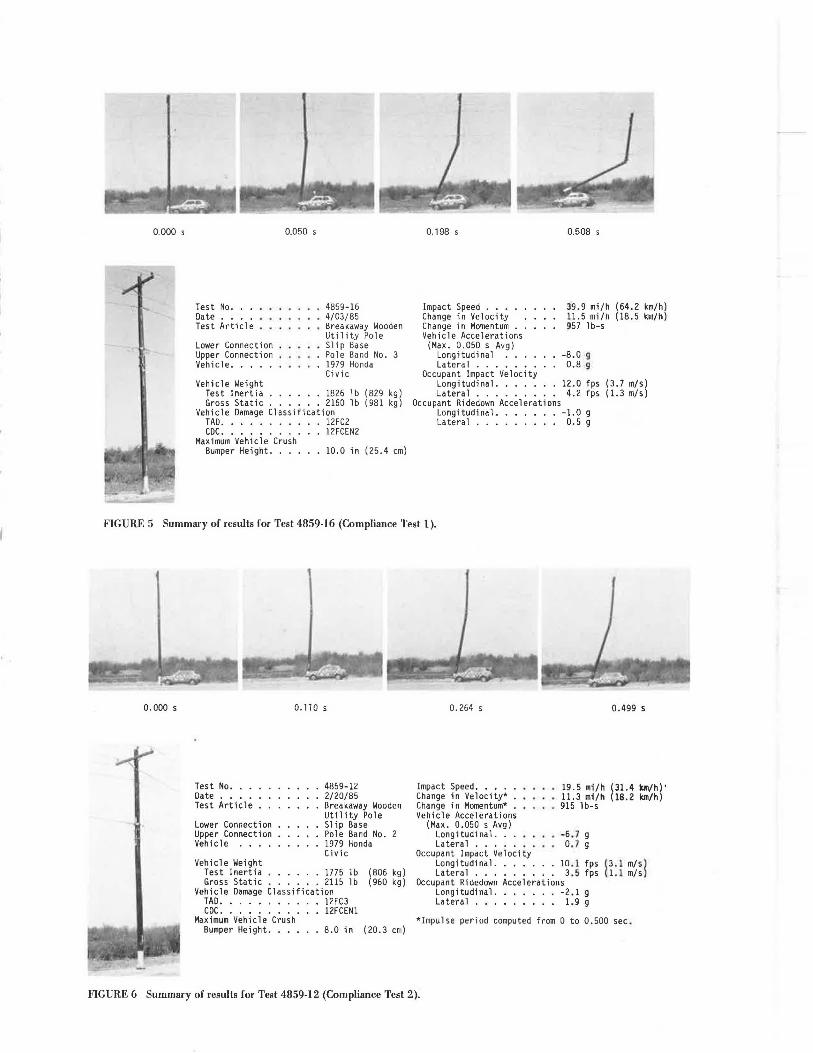
4859-16 4/03/85 Breakaway Wooden Ut il i ty Pole Slip Base Pole Band No. 3 1979 Honda Civic
Test Inertia ...... 1826 lb (829 kg) Gross Static ...... 2160 lb (981 kg)
Vehicle Damage Classification TAD. . . . . . . . . 12FC2 CDC. . . . . . . . . 12FCEN2
Maximum Vehicle Crush Bumper Height. . . . 10.0 in (25.4 cm)
0.198 s
Impact Speed . . . . . Change in Velocity . Change in Momentum .. Vehicle Accelerations
(Max. 0.050 s Avg) Longitudinal Lateral ...•.•
Occupant lmpact Velocity
0.508 s
39.9 mi/h (64.2 km/h) 11.5 mi/h (18.5 km/h) 957 l b-s
-8.0 g 0.8 g
Longitudinal. . . . . 12.0 fps (3.7 m/s) Lateral ......... 4.2 fps (1.3 m/s)
Occupant Ridedown Accelerations Longitudinal ....... -1.0 g Lateral ......... 0.5 g
FIGURE 5 Summary of results for Test 4859-16 (Compliance Test 1).
0.000 s 0. 110 s
Test No. . . Date .... Test Article
Lower Connection Upper Connection Vehicle ...
Vehicle Weight
4859-12 2/20/85 Breakaway Wooden Utility Pole Slip Base Pole Band No. 1979 Honda Civic
Test Inertia ...... 1775 lb (806 kg) Gross Static ...... 2115 lb (960 kg)
Vehicle Damage Classification TAD. . . . . . . . . 12FC3 CDC. . . . . . . . . 12FCEN1
Maximum Vehicle Crush Bumper Height. . . . 8.0 in (20.3 cm)
0.264 s
Impact Speed ..... Change in Velocity* . Change in Momentum* . Vehicle Accelerations
(Max. 0.050 s Avg) Long i tud i na 1. . . Lateral .....
Occupant Impact Velocity
0.499 s
19.5 mi/h (31.4 bl/h)' 11.3 m1/h (18.2 km/h) 915 1 b-s
-6.7 g 0.7 g
Longitudinal. . . . . 10.1 fps (3.l m/sl Lateral ......... 3.5 fps (1.1 m/s
Occupant Ridedown Accelerations Longitudinal ....... -2.1 g Lateral . • . . . . . . . 1.9 g
*Impulse period computed from 0 to 0.500 sec.
FIGURE 6 Summary of results for Test 4859-12 (Compliance Test 2).

-- ~ 0. 000 s
Test No .. . Date ... . Test Article
Lower Connection Upper Connection Vehicle . ...
Vehicle Weight
0.049 s
4859-13 2/ 27/85 Breakaway Wooden Utility Pole Slip Base Pole Band No. 2 1980 Chevrolet Mali bu
0. 243 s
Impact Speed . . . . . Change in Velocity Change in Momentum .. Vehicle Accelerations
(Max. 0.050 s Avg) Longitudinal Lateral . .... . ,
0. 607 s
. 40.7 mi/h (65.5 km/h)
. 10 .8 mi/h (17.4 km/h) 1655 lb-s
-6.7 g 1.4 g
Occupant Impact Velocity Longitudinal. . . . . 11 .9 fps (3.6 m/s)
Test Inertia ...... 3365 lb (1528 kg) Lateral . . . . . . . 6.3 fps (1.9 m/s) Gross Static ...... 3700 lb (1655 kg) Occupant Ridedown Accelerations
Vehicle Damage Classification Longitudinal. -1.4 g TAD. . . . . . . . . 12FC 5 Lateral . . . . • . . . • 1.1 g CDC. . . . . . . . . 12FCEN2
Maximum Vehicle Crush Bumper Height. . . . IB.7 in (47.5 cm)
FIGURE 7 Summary of results for Test 4859-13 (Compliance Test 3).
Test No ..• Date .... Test Article
Lower Connection Upper Connection Vehicle ...•
Vehicle Weight
48~~-14 3/22/85 Breakaway Wooden Utility Pole Slip Base Pole Band No. 3 1975 Chevrolet · Vega
Test Inertia ...... 2500 lb (1135 kg) Gross Static . . • . . . 2830 1 b (1285 kg)
Vehicle Damage Classification TAD. • . . . . . . . 12FR3 CDC. . . . . . . . . 12FREN2
Maximum Vehicle Crush Bumper Height. . . . 15.0 in (38.1 cm)
Impact Speed . . . . . Change in Velocity . Change in Momentum .. Vehicle Accelerations
(Max. 0.050 s Avg) Longitudinal Lateral ..•..•.
60.0 mi/h (96.5 km/h) 11.0 mi/h (17.7 km/h) 1253 l b-s
-10.2 g - 1.3 g
Occupant Impact Velocity Longitudinal. . . . . 15.6 fps (4.8 m/s) Lateral . . . . . . . . . No Contact
Occupant Ridedown Accelerations Longitudinal. . -1.8 g Lateral . . . . . . . . . NA
FIGURE 8 Summary of results for Test 4859-14 (Compliance Test 4).

0.000 s
Test No ... Date .•.. Test Article
Lower Connection Upper Connection Vehicle ... .
Vehicle Weight
0.101 s
4859-5 6/29/84 Breakaway Wooden Utility Pole Slip Base Pole Band No. 2 1979 Chrysler Newport
Test Inertia . . • .... 4331 lb (1966 kg) Gross Static .. ..... 4665 lb (2118 kg)
Vehicle Damage Classification TAD. . . . • . . . . 12FC4 CDC. . . . . . . . . 12FCEN3
Maximum Vehicle Crush Bumper Height . Hood Height ...•.
28 .0 in (71.1 cm) 22.0 in (55.9 cm)
0. 218 s
Impact Speed .. • .• Change in Velocity . . Change in Momentum .. Vehicle Accelerations
(Max. 0.050 s Avg) Longi·tudinal . . . Lateral . • . . .
Occupant Impact Velocity
0.415 s
. 56.8 mi/h (91.4 km/h) 7.0 mi/h (11.3 km/h) 1487 l b-s
-4.9 g 0.6 g
Longitudinal. . • • . 10.7 fps (3.3 m/s) Lateral . • . • • • . . . None
Occupant Ridedown Accelerations Longitudinal . . . -0 .8 g Lateral . . • . • . . . . No Contact
FIGURE 9 Summary of results for Test 4859-5 (Compliance Test 5).
TABLE 2 Injury Rate Levels for Compliance Tests
O.OSO-sec Avg Probability of Injury for Change in Velocity Change in Momentum Acceleration Unmodified Pole
Test 6V AIS;. I AIS;. 3 6M AIS;. 1 No (mph) (%) (%) (lb-sec) (%)
I 11.5 66.0 l.42 987 S2.3 (16) 2 11.3 65.7 1.39 91S S l.S ( 12) 3 10.8 64.9 1.31 l,6SS 61.5 (! 3) 4 11.0 6S.3 1.34 l,2S3 S6.8 (14) s 7.0 S7.2 0.83 1,487 59.7
Note: numbers in parentheses refer to test numbers described in the text.
TABLE 3 Probability of Injury Equations
Description
Mak and Mason (5) Percentage AIS as a function of momentum
change, 6M (lb-sec) Mak and Mason (5) Percentage AIS as a function of impact speed,
V (mph) Mak and Mason (5) Percentage AlS as a function of change in velocity, 6 V (mph)
Buth and Ivey (JO) Probability of injury(%) as a function of
highest resultant SO-msec acceleration, Ar (~'s)
AIS;. 3 PI AIS;. I AIS;;. 3 (%) _g_ (%) (%) (%)
0.38 8.0 21.5 81.3 22.4
0.36 6.7 IS.I 70.2 2.S
0.74 6.77 IS.I 81.3 22.4
a.so 10.2 3S.O 87.8 76.S
0.63 4.9 8.1 72.6 2.S8
Equation
% AIS ;. J = -63.S + 16.87 Ln(6M)
% AIS ;;. 3 = JOO/[ l + e65-0.00097(llM)J % AJS ;. J = 22.2 + 16.03 Ln(V)
% AIS ;. 3 = 100/[1+e6.os-o.121(V)] % AIS ;;. I = 22.S + 17.83 LN(V)
% AIS ;;. 3 = I 00/[ 1 + e5.62-0.t2(6V)J
PI= 0.336 Ar P = 0.336 Ar
Pl (%)
100
60
66
79
26.S

8
100
75
" Cf1
<[
I- 50 z w u a:: w a_
25
INJURY
AIS? I
fZI UNMODIFIED POLE (MAK et ol.)(IO)
D H8S COMPLIANCE TESTS
87.8%
20 40 60
IMPACT VELOCITY, MPll
FIGURE 10 Comparison of injury levels from HBS compliance tests with unmodified pole injury levels (% AIS 1).
rate levels for any test can be seen by examining Table 2, it is somewhat easier to compare those levels using Figures 10 and 11. These bar graphs were developed for each test speed using Method 1 and present the average injury level for all tests at that speed. In Figure 10 it is seen that a significant improvement results. The greater improvement, however, is shown by Figure 11. A major decrease in the AIS > 3 injury rate is demonstrated. This decrease, for - the five compliance tests conducted, averages 91 percent. It is apparent from
100
r<l
" VJ
<t
I- 50 z w u a: w a_
SERIOUS INJURY
AIS ? 3
~ UNMODIFIED POLE (MAK etal .l(IO)
D HBS COMPLIANCE TESTS
76.5%
20 40 60
IMPACT VELOCITY, MPH
FIGURE 11 Comparison of injury levels from HBS compliance tests with unmodified pole injury levels (% AIS 3).
Transportation Research Record 1065
Figure 11 that the reduction becomes more pronounced as the speed increases. There is a slight advantage at 20 mph that progresses to a major improvement at 60 mph. For the 40- and 60-mph test conditions, the probability of injury greater than AIS = 3 is reduced by 97 percent.
Finally, Figure 12 was constructed using all available test data and a computer simulation. This figure shows the various zones of interaction between vehicles and RBS-modified poles. It also shows the calculated failure boundary for unmodified Class 4 timber utility poles. The activation boundary for the HBS occurs at about 10 mph for small vehicles and will decrease slightly as vehicle weight increases. As speed increases, the next zone is where the lower connection is activated and the pole is pushed in front of the impacting vehicle. The vehicle then stops and the pole leans on or descends on the vehicle. The velocity of the falling pole is so low that significant passenger compartment intrusion will not occur. This was illustrated by Compliance Test 2.
In the next zone the vehicle will go completely under the pole, but the pole will make contact with the roof or truck structure as the vehicle moves through. Passenger compartment intrusion will be minimal in this zone because of the rotation of the lower pole segment to a position where it will glance off or be pulled across the roof structure. The zone is not precisely defined but will vary as vehicle structural stiffness and coefficient of restitution vary. Finally, the zone where the pole clears the vehicle after impact is everywhere to the right of Curve C. This is the zone illustrated by compliance Tests 1 and 3-5.
COMPLIANCE WITH NCHRP REPORT 230
It should be recognized that the recommendations for timber utility poles were considered extremely tentative by the writer of NCHRP Rt!!Jurt 230 (_§_). The development of breakaway devices for these structures was in its infancy and no one was sure it could be done. The recommendations for "Occupant/Compartment Impact Velocity" and "Occupant Ride Down Acceleration" were based more on what the author considered possible than on what would be preferred. In Table 8 of NCHRP Report 230, an acceptance factor of 1. 3 3 was i:ecommended. This resulted in values of 6V of 30 fps and acceleration of 15 .9.'s.
It appears now that breakaway timber utility poles can be engineered to perfoi:m significantly better than the values that were recommended in 1981 would indicate. This can be seen by comparing the results of tests recommended in NCHRP Report 230 for breaka way on y i elding supports to the values of velocity change and acceleration given previously in this paper. Table 4 gives this comparison. The required tests are 60 and 61, although in this case test 61 is substituted for 60i 62 is a more demanding test. The other test conducted was not required but is described as a possible supplementary test in Table 4 of NCHRP Report 230 (§_). This is Test 864, an 1,800-lb vehicle at 40 mph impacting at the center of the bumper.
As can be seen, the HBS results are well below the maximum values given by NCHRP Report 230 for timber utility poles and fundamentally meet the requirements for signs and luminaire supports. They are well within the requirements for r idedown acceleration and, with one exception, meet the occupant/compartment impact velocity. That exception is Test 61 in which a 6V of 15. 6 fps was observed, compared with a recommended limiting value of 15 fps. Given the variability in crash testing,

Ivey and Morgan
en ID ....I
4000
1--::c 3000 Q w ~ w ....I (.)
:i: w >
2000
Zone ol Slip Base
non-aclivalion
\ \ \ \ \ \
\ Prot>a ble \
\ Zono o! \
Zone of Pole \Po le Conta c l \
Leaning or
Settling On
Vehicle Aller
Vehicle Stops
\Vehi c le Goes
\ Under Pole
\ \ \ \ \ • B
9
Utility Pole
c
1000
Activation Boundary
Breakaway ! Hawkins!
Timber Util i ty Po le
10 20 30 40 50 60
VEHICLE SPEED, MPH
FIGURE 12 Zones of vehicle-pole interaction.
there is no reason to be overly concerned by this result. It appears that an acceptance factor higher than the 1. 33 value proposed in 1981 might be considered for timber utility poles.
CONCLUSION
A breakaway design for the modification of timber utility poles that will radically increase the safety of passengers in impacting vehicles has been developed and comprehensively tested. It is called the Hawkins breakaway system (HBS). This system not only accomplishes the goal of increasing safety but exhibits characteristics of significant advantage to a utility company.
An alternate safety criterion to be applied in the evaluation of roadside structures also has been developed. It can be used as the basis for evaluation of any proposed safety improvement relative to roadside geometry and structures. It was used to develop compliance tests for breakaway utility poles, but its applicability is general to the roadside environment.
Analysis of the literature relative to the costeffectiveness of breakaway utility poles reveals that there will be a positive societal benefit as-
TABLE 4 NCHRP Report 230 Compliance Tests
Weight Speed NCHRP TT!
sociated with carefully selected applications. The work of Zegeer and Cynecki (~) may be used to define appropriate applications, although Sicking and Ross (11) have recently developed a somewhat more comprehensive benefit-cost analysis.
Detailed conclusions are
• The HBS has been adapted and applied to 40-ft, Class 4 timber utility poles (4/0 construction). The primary system developed for this type of construction consists of a slip base, an upper hinge mechanism, and overhead guy support cables. This adaptation of the HBS virtually eliminates the chance of serious injury in a wide range of vehicle collisions.
• Excellent performance has been achieved for vehicles ranging from 1,800 to 4,500 lb at speeds of from 20 to 60 mph. Mak and Mason (~) have found that there is little chance of serious injury at speeds lower than 20 mph, even for an unmodified pole.
• The original cost of the HBS for a single pole modification should be less than $800. It is estimated that a three-person crew with a diggerderrick and insulated aerial device can make all of the necessary repairs within a 4-hr period following an accident. Assuming an area with congested traf-
11V
Test Test Suggested Achieved Suggested Achieved Suggested Achieved Suggested Achieved Designation Designation (lb) (lb) (mph) (mph) (fps) (fps) (s._'s) (~'s)
61 (substitute for 60) 4859-14 2,250 2,500 60 60.0 30 15.6 15 1.8 62 4859-1 2 1,800 1,775 20 19.5 30 10.l 15 2.1 564 4859-16 1,800 1,826 40 39.9 30 12.0 15 1.0

10
- +
I
!l
Transportation Research Record 1065
End view
Side view
Fully activated upper connection
FIGURE 13 HES-modified utility pole after a high-speed collision (Test 4859-3 )-
fie, energized electric power lines, and night work conditions, the manpower, material (including a new pole but excluding breakaway hardware), and equipment costs are estimated at $875. Because a new pole will not always be required, the average cost may be somewhat lower. In addition, some of the breakaway hardware may need to be replaced (miscellaneous nuts and bolts and a keeper for low-speed impacts, plus two straps in higher speed impacts). The cost for replacement of breakaway hardware should b e l ess than $150.
• On the basis of the results of the compliance tests reported here, it appears that most other types of Class 4 construction could be treated in a similar manner, yielding similar results.
The HBS is ready for implementation. Used selectively, it holds the potential to make a significant reduction in the 1,600 deaths and 100, 000 injuries that occur annually as a result of collisions with timber utility poles <!l) . In addition, significant advantages to utility companies will accrue as selective implementation is undertaken <l>· One major benefit is illustrated by Figure 13. After a vehicle collision, a utility maintenance crew will find a shortened pole, with conductors still intact and functioning, instead of a tangle of conductors and broken pole segments.
ACKNOWLEDGMENT
This paper is dedicated to Dr. Robert M. Olson, Professor Emeritus of Texas A&M University, who died suddenly on April 4, 1986. He had a major influence on the lives of both authors and was a continual source of inspiration during a 25-year period as both teacher and associate. Dr. Olson worked with D.L. Hawkins in the late 1960s to develop the nat i onally accepted breakaway highway signs. The development of the Hawkins breakaway system for utility poles was grounded firmly on their pioneering efforts.
The influence and inspiration of Bob Olson will live on in the students he taught and in the associates he so unselfishly helped. The present authors are two among the many.
REFERENCES
1 . G.K. Wolfe and J.D. Michie. Development of Breakaway Concepts for Timber Utility Poles. SwRI Report on Project 03-3282. Southwest Research Institute, San Antonio, Tex., Feb. 1973.
2 . J .J : Labra, C.E. Kimball, Jr., and C.F. McDevitt. Development of Safer Utility Poles. In Transportation Research Record 942, TRB, Na-

Ivey and Morgan
tional Research Council, Washington, D.C., 1983, pp. 42-53.
3. T.C. Edwards. Multidirectional Slip Base for Breakaway Luminaire Supports. Research Report 75-10. Texas Transportation Institute, Texas A&M University System, College Station, Aug. 1967.
4. R.M. Olson, N.J. Rowan, and T.C. Edwards. Break-Away Components Produce Safer Roadside Signs. In Highway Research Record 174, HRB, National Research Council, Washington, D.C., 1967, pp. 1-29.
5. K.K. Mak and R.L. Mason. Accident Analysis-Breakaway and Nonbreakaway Poles Including Sign and Light Standards Along Highways, Vol. 2: Technical Report. Report DOT-HS-805-605. FHWA, U.S. Department of Transportation, Aug. 1980.
6. J.D. Michie. Recommended Procedures for the Safety Performance Evaluation of Highway Appurtenances. NCHRP Report 230. TRB, National Research Council, Washington, D.C., March 1981 .
7. D.L. Ivey and J.R. Morgan. Safer Timber Utility Poles. Texas Transportation Institute, Texas A&M University, College Station, Vol. 1: Draft Final Report, June 1985, 231 pp.
8. c.v. Zegeer and M,J. Cynecki. Determination of Cost-Effective Roadway Treatments for Utility Pole Accidents. !.!). Transportation Research Record 970, TRB, National Research Council, Washington, D.C., 1984, pp. 52-64.
9. Recommended Procedures for Vehicle Crash Test-
11
ing of Highway Appurtenances. In Transportation Research Circular 191, TRB, National Research Council, Washington, D.C., Feb. 1978.
10. C.E. Buth et al. Safer Bridge Railings. Report FHWA/RD-82/072. FHWA, U.S. Department of Transportation, Vol. 1: Summary Report, June 1984.
LL N.L. Graf, J.B. Boos, and J.A. Wentworth. Single-Vehicle Accidents Involving Utility Poles. In Transportation Research Record 571, TRB, National Research Council, Washington, D.C., 1976, pp. 36-43.
11. D.L. Sicking and H.E. Ross, Jr. Comprehensive Benefit-Cost Warrants for Roadside Safety Appurtenances. FHWA Project DTFH-82K-0078. FHWA, u.s. Department of Transportation, June 1985.
This paper is based on work performed under Federal Highway Administration Contract DTF461-83-C-00009, "Safer Timber Utility Poles." Charles F. McDevitt is the Contracting Officer Technical Representative. The more detailed complete report, "Safer Timber Utility Poles," Volumes 1 and 2, will be available after November 1985.
The contents of this paper reflect the views of the Texas Transportation Institute, which is responsible for the facts. and accuracy of the data presented. The contents do not necessarily reflect the official policy of the U.S. Department of Transportation.