time division switching - bharath institute of higher
TRANSCRIPT
Time division Switching
1
2
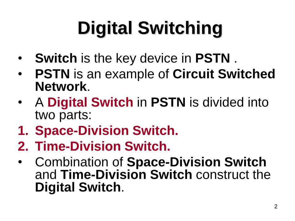
Digital Switching
• Switch is the key device in PSTN .
• PSTN is an example of Circuit Switched Network.
• A Digital Switch in PSTN is divided into two parts:
1. Space-Division Switch.
2. Time-Division Switch.
• Combination of Space-Division Switch and Time-Division Switch construct the Digital Switch.
3
• Crossbar Switch is also known as
Space-Division Switch.
• Space Division refers to the fact that
speech paths are physically separated
in space.
• In Space-Division Switching, a metallic
path is set up between calling and called
subscriber.
4
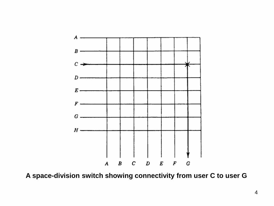
A space-division switch showing connectivity from user C to user G

5
• Time-Division Switch is also known as Time-Slot Interchanger (TSI).
• It permits a single common metallic path to be used by many calls separated one from the other in the time domain.
• With Time-Division Switching, the speech to be switched is digital in nature (PCM).

6
• Where, samples of each telephone call are
assigned time-slots, and PCM switching
involves the distribution of these slots in
sequence to the desired destination port(s) of
the switch.
• Internal functional connectivities in the switch
are carried out by digital highways.
• A highway consists of sequential speech
path time-slots.
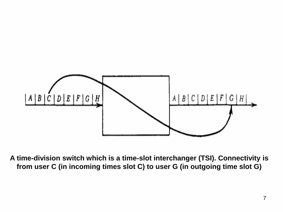
7
A time-division switch which is a time-slot interchanger (TSI). Connectivity is
from user C (in incoming times slot C) to user G (in outgoing time slot G)
8
• A classical Digital Switch is made up of two functional elements:
1. A Time Switch called “T”.
2. A Space-Switch called “S”.
• The architecture of a digital switch is described in sequences of Ts and Ss.
• For example, the 4ESS is a TSSSST switch.
• Where, the input stage is a time switch, followed by four space switches in sequence and the last stage is a time stage.
9
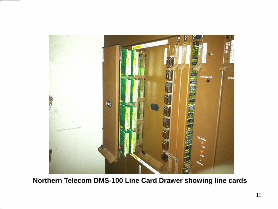
• Another example, the Northern Telecom
DMS-100 is a TSTS switch that is folded
back on itself.
• Many of the new switches or enhanced
versions of the switches just mentioned
have very large capacities (e.g.,100,000
lines) and are simply TST or STS
switches.
10
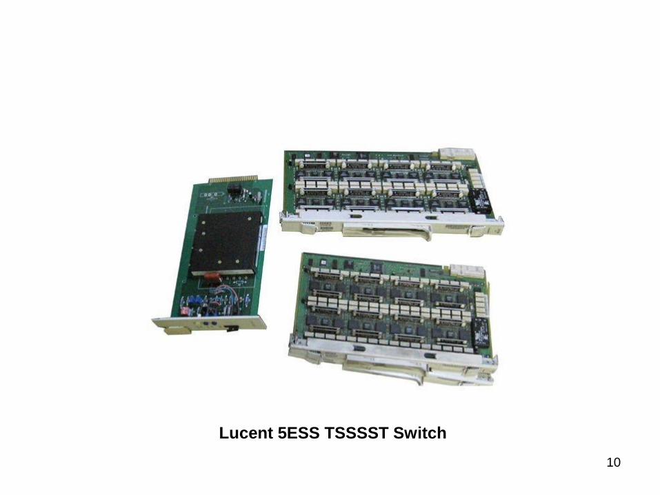
Lucent 5ESS TSSSST Switch
11
Northern Telecom DMS-100 Line Card Drawer showing line cards

12
Time Switch
• Time-Division Switch or simply, Time-Switch is a Time-Slot Interchanger (TSI).
• We know that E1 consists of 32 time-slots in 125 µs, with time slot duration of 3.906 µs, and each time-slot contain 8-bits.
• TSI involves moving the data contained in each time-slot from the incoming bit stream at the switch inlet ports, to an outgoing bit stream at the switch outlet ports, but with a different time-slot arrangement in accordance with the destination of each time-slot.

13
• To accomplish this, at least one time-slot
must be stored in memory (Write) and then
called out of memory in a changed position
(Read).
• The operations must be controlled in some
manner, and some of these control actions
must be kept in memory together with the
software managing such actions.
• Typical control functions are time-slot
“idle” or “busy”.
14
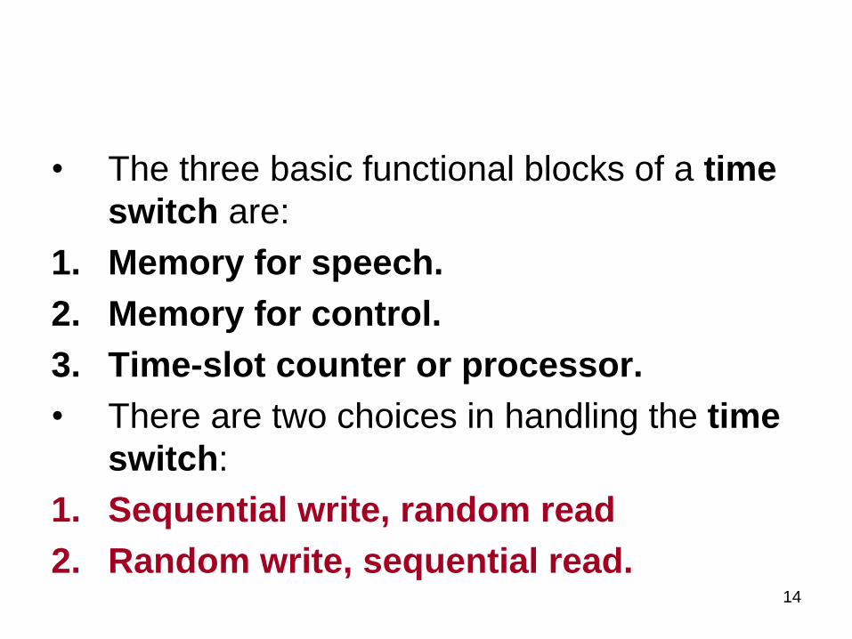
• The three basic functional blocks of a time
switch are:
1. Memory for speech.
2. Memory for control.
3. Time-slot counter or processor.
• There are two choices in handling the time
switch:
1. Sequential write, random read
2. Random write, sequential read.
15
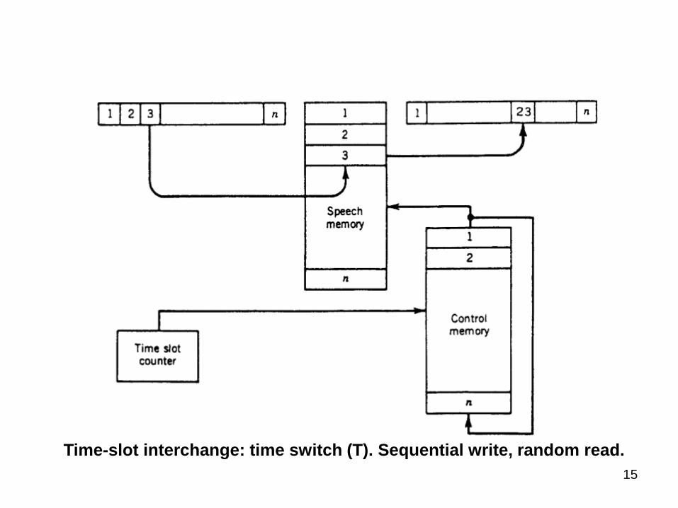
Time-slot interchange: time switch (T). Sequential write, random read.
16
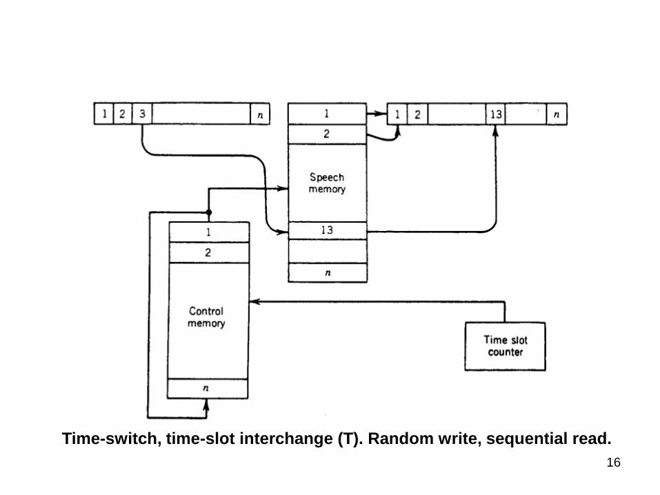
Time-switch, time-slot interchange (T). Random write, sequential read.

17
• With sequential write, the time-slots are written into the speech memory as they appear in the incoming bit stream.
• With random write, the incoming time-slots are written into memory in the order of appearance in the outgoing bit stream (the desired output order).
• The writing of incoming time-slots into the speech memory can be controlled by a simple time-slot counter and can be sequential (e.g., in the order in which they appear in the incoming bit stream).
18
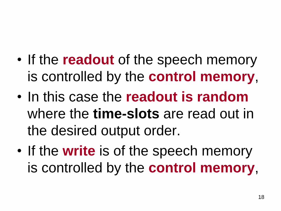
• If the readout of the speech memory
is controlled by the control memory,
• In this case the readout is random
where the time-slots are read out in
the desired output order.
• If the write is of the speech memory
is controlled by the control memory,
19
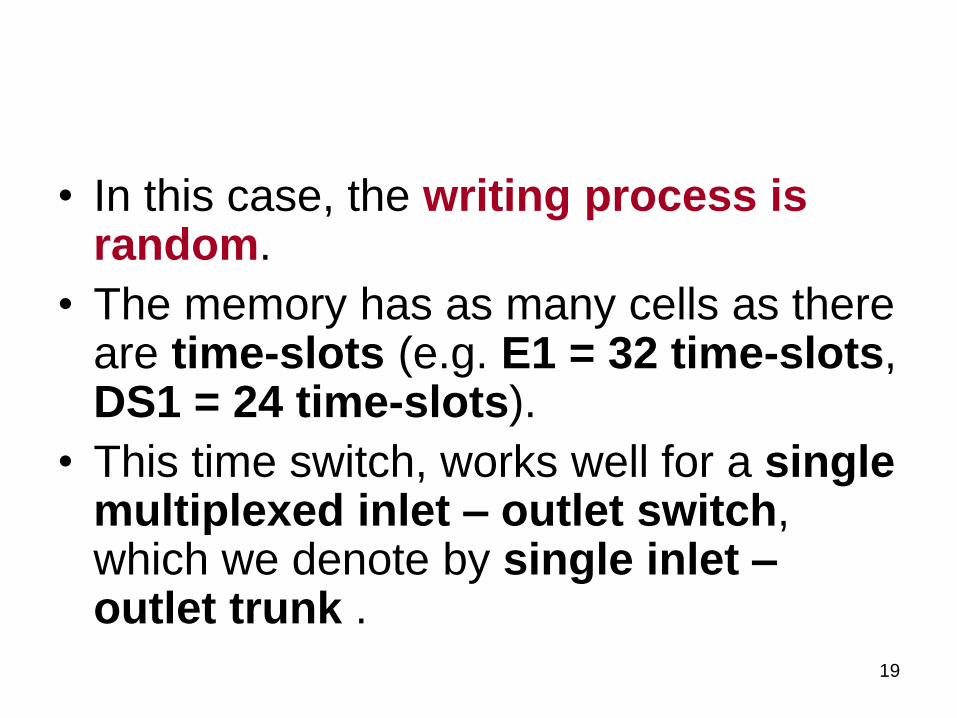
• In this case, the writing process is random.
• The memory has as many cells as there are time-slots (e.g. E1 = 32 time-slots, DS1 = 24 time-slots).
• This time switch, works well for a single multiplexed inlet – outlet switch, which we denote by single inlet – outlet trunk .

20
• How can we increase a switch’s capacity?
• Enter the space switch (S). (see the figure in the next slide)
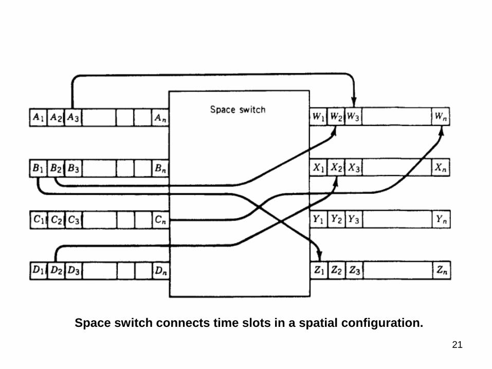
• For example, time-slot B1 on the B trunk is moved to the Z trunk into time-slot Z1, and time-slot Cn is moved to trunk W into time-slot Wn.
• However, we see that there is no change in time-slot position.
21
Space switch connects time slots in a spatial configuration.

22
Space Switch
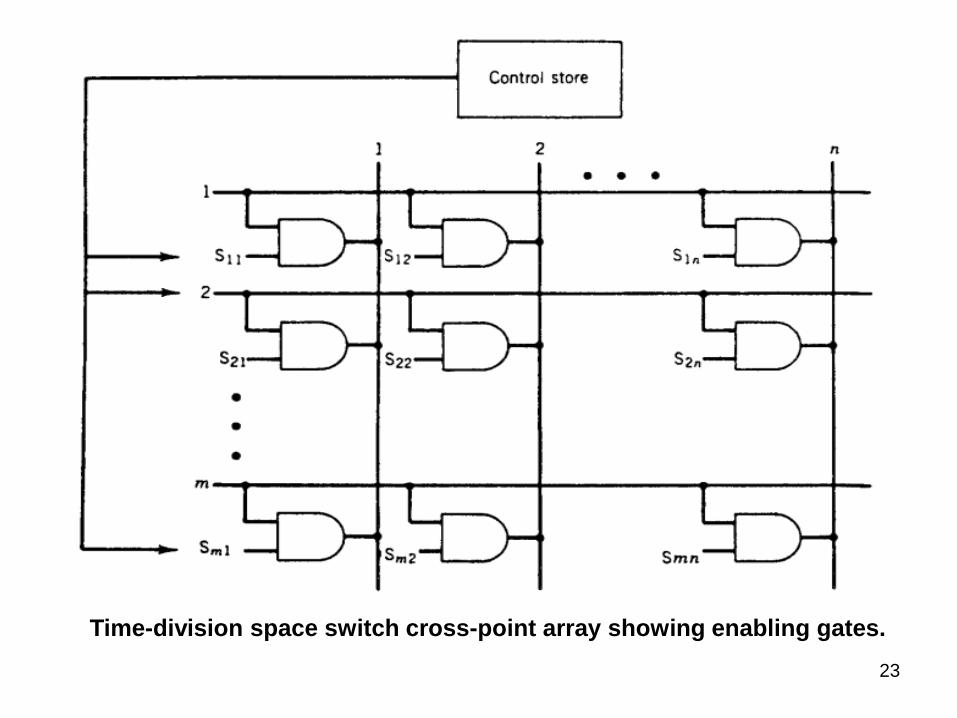
• Figure in the next slide illustrates a typical time-division space switch.
• It consists of a Cross-Point Matrix made up of Logic Gates that allow the switching of time-slots in the spatial domain.
• These PCM time-slot bit streams are organized by the switch into a pattern determined by the required network connectivity.
23
Time-division space switch cross-point array showing enabling gates.
24
• The matrix consists of a number of
input horizontals and a number of
output verticals with a Logic Gate
at each cross-point.
• The array, as shown in the figure, has
M input horizontals and N output
verticals, and we call it an M × N
array.
25
• If M = N, the switch is Non-blocking.
• If M > N, the switch Concentrates;
• If N > M, the switch Expands.
• For a given time-slot, the appropriate
Logic Gate is enabled and the time-
slot passes from the input horizontal
to the desired output vertical.