time overcurrent relay with torque control model · 2014-08-01 · instructions time overcurrent...
TRANSCRIPT

INSTRUCTIONS
TIME OVERCURRENT RELAY WITH TORQUE CONTROL
TYPE IAC
GEK-28046AInserl Booklet GEH-2059
MODEL 12IAC9OA(-)Al21.AC9OB(-)A
INTRO DuCT ION
These instructions plus those included in GEH-2059 form the instructions
for these relays.
DESCRIPTION
Relay model IAC9OA(-)A is an extremely inverse time characteristic
induction disk time overcurrent relay with torque control. It consist of
a wattmetric construction EAC type time overcurrent unit with a targetseal-in unit mounted in a small single ended drawout (Si) case. Thisrelay is similar to relay model IAC77A(-)A described in GEH-2059 except:
1. The internal connections are shown in Fig. 1 and the outlineand panel drilling in Fig. 3 of this supplement.
2. This relay has torque control. The floating winding circuit of
the IAC unit operating coil is brought out to relay terminals 7-8.
When this floating winding is open circuited, it does not produce aphase displacement of flux and the JAC unit does not develop operating torque.
With the floating winding circuit open, this relay will not pick upon overcurrent levels up to 20 times tap value. With the floatingwinding circuit short-circuited, the characteristics of this relayare similar to those of the IAC77A described in GEH-2059.
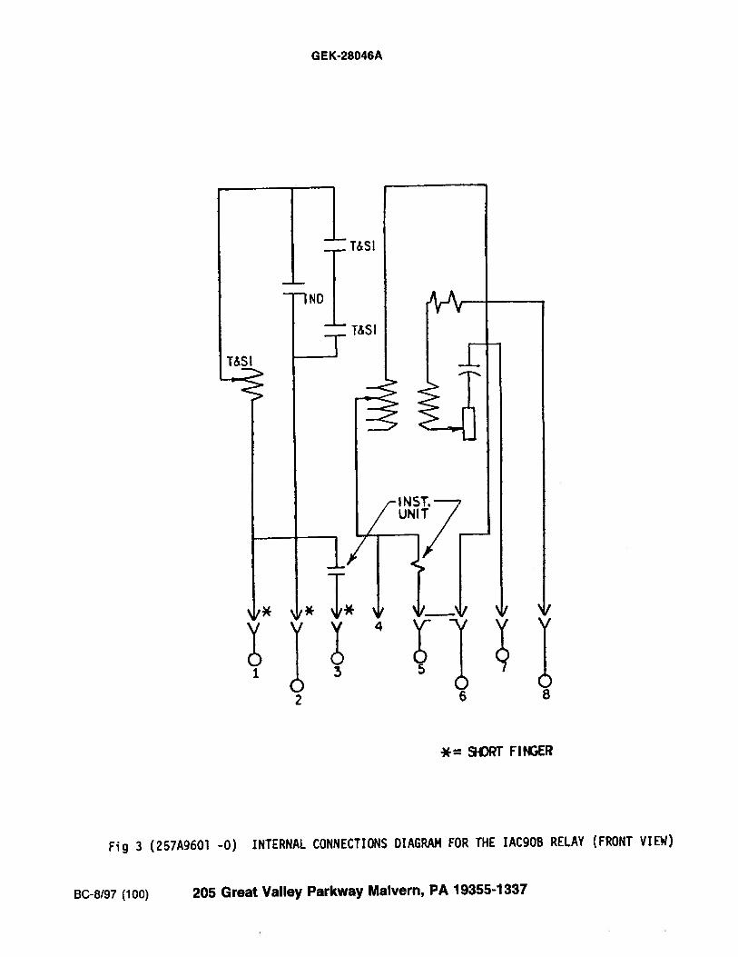
3. Relay Model IAC9OB(-)A is similar to IAC9OA(-)A exceptfor addition of an instantaneous unit. The internal connections areshown in Fig. 3 of this supplement.
POWER SYSTEMS MANAGEMENT DEPARTMENT
GENERAL ELECTRIC
These instructions do not purport to cover all detaLls or variations in eqaipent nor to provide for
every possible contingency to be t in connection with installation, operation or maintenance. Should
further information be desired or should particular problems arise which are not covered sufficiently for
the purchaser’s purposes, the matter should be referred to the General Electric Corrçany.
To the extent required the products described herein meet applicable ANSr, IZtE and NEM.4 standards;
but no such assurance is given with respect to local codes and ordinances because they vary greatly.
PHILADELPHIA, PA.

GEK-28046A
= SHORT FINGER
FIG. 1 ( 0207A7845—O ) INTERNAL CONNECTION DIAGRAM FOR THE IAC9OA RELAY (FRONT NEW)
1! S I
11
2

GEK-28046A
jLJ
wort
)-0<bJ
JI—
i 57000000000
‘—2 4 6 8 SO-’
NUMBERING OF STLUS(FRONT YEW)
OUTLINE
DRLL2 HOLES
PANEL
/
- ORIL L0 1-IcLES
PANEL DRLLIHG FOR SEMI-FLUSHMOUNTING (FRONT VIEW’)
Li
S TUO
PANEL £ILLING FOR SURFACEMOUNTING (FRONT VEW
VIEW SHOWG ASSEMBLY QFHARDWARE FOR SURFACE r’TG.
ON STEEL PANELS
OUTLINE AND PANEL DRILLING FOR RELAY TYPES IAC99A and 1AC998FIG 2 (K-6209271 3
3
GEK-28046A
* 9-ORT FINGER
Fig 3 (257A9601 -0) INTERNAL CONNECTIONS DIAGRAM FOR THE IAC9OB RELAY (FRONT VIEW)
BC-8/97 (100) 205 Great Valley Parkway Malvern, PA 19355-1337

INSTRUCTIONS GEH-2059C
Types:
LAC77A Form 11 and Up
IAC77B Form 31 and Up
LAC78A Form 4 and Up
IAC78B Form 11 and Up
GENERAL ELECTRIC
Time Overcurrent Relays

GEH- 2059
CONTENTS
PAGE
INTRODUCTION 3APPLICATION 3RATINGS 3
INDUCTION UNIT 3TABLE I 4TABLE II 4TABLE IIA 4
INSTANTANEOUS UNIT 4SEAL-IN UNIT 4
TABLE III 4CONTACTS 4
BURDENS 5TABLE IV 5TABLE V 5RECEIVING, HANDLING AND STORAGE 5DESCRIPTION 5RELAY TYPES 5INDUCTION UNIT SSEAL-IN UNIT 6INSTANTANEOUS UNIT 6INSTALLATION 6
LOCATION 6MOUNTING 6CONNECTIONS 6CAUTION 6
AOJUSTMENTS 6INDUCTION UNIT 6TIME SETTING 1
EXAMPLE OF SETTING 7INSTANTANEOUS UNIT 1TARGET AND SEAL-IN UNIT 1
MAINTENANCE 8DISK AND BEARINGS 8ACCEPTANCE TESTS 8
A. MAIN UNIT 8PICKUP 8TIME TEST 8
B. INSTANTANEOUS UNIT 8PICKUP 8
C. TARGET SEAL IN UNIT 8PICKUP 8DROPOUT 8
PERIODIC TESTS 8CONTACT CLEANING 9
RENEWAL PARTS 9
2

GEH -2 059
TIME OVERCURRENT RELAY
TYPE IAC
INTRODUCTION
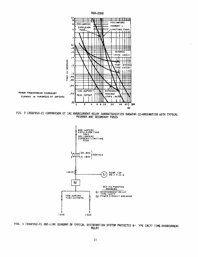
These relays are of the induction disk construction with a wattmetric type current operating element.They have an extremely—inverse time—current characteristic as shown in Fig. 6.
— NUMBER N.O. INSTANTANEOUSCONTACT OUTPUTS UNIT
f IAC77A 1 NOIAC77B I YESIAC7SA 2 * NOIAC78B 2 * YES
* Not electrically separate - see Figure 12.
APPLICATION
The extremely inverse time current characteristics of the 1AC77 and 1AC78 relays make these relaysparticularly well suited for the protection of primary distribution feeder circuits.
In such applications, because the relay characteristics closely parallel those of power fuses, itis possible to obtain selective fault protection with a minimum time delay. For example, the systemillustrated in Fig. 3, it is necessary that the protective relays (device 51) co—ordinate with the fuseson the high side of the power hank as well as with those on the load side of the power circuit breaker.Fig. 2 illustrates that tFis can be done most effectively with extremely inverse 1AC77 or 1AC78 relayswhose characteristics most nearly parallel those of the fuses.
The extremely inverse relay also is better suited than both the inverse and veryinverse relaysfor picking up cold load. For any given cold load pick up capability, the resulting settings will providefaster protection at high fault currents with the extremely inverse relay than with the less inverse relays.
The zero current reset time of the extremely inverse 1AC77 and 1AC78 is approximately 60 secondswhen set on time dial 10. For other- time dial settings the zero current reset time is proportionatelyless. For example, the reset time from time dial 2 is approximately 12 seconds.
RATINGS
INDUCTION UNIT
Ratings of the induction unit are given in Table I.
These instructions do not purport to cover all details or variations in equipment nor to provide forevery possible contingency to be met in connection with installation, operation or maintenance. Shouldfurther information be desired or should particular problems arise which are not covered sufficiently forthe purchasers purposes, the matter should be referred to the General Electric Company.
To the extent required the products described herein meet applicable ANST, IEEE and NEMA standards;but no such assurance is given with respect to local codes and ordinances because they vary greatly.
3

GEH -2 059
TABLE I
CURRENT (WEB. 2JNGE, AMPERESRELAY FREQ.
MAIM (TI1EJ INSTANTAMEOUSCYCLESUNIT UNIT
TAC77A 4—16& 60 1.5—6
IAC78A 0.5-20.1—0.4
4-16 20-80IAC77B I 4—16 10—40
&P 60 1.5—6 10—401AC788 I 0.5-2
The continuous and one—second thermal ratings are listed in Table ft.
TABLE II
INDUCTION UNIT RATING *C0ITINU0!JS RATIIG ONE—SEC. RATING(A1PS) (AMPS) (AMPS)
4—16 13 2601.5—6 6 20005—2 3 650.1—0.4 1 15
* The continuous rating of the coil circuit which appears in the table applies to all induction—unittaps up to, and including, the value of the rating. For taps above this value the rating is the same asthe tap value.
Continuous rating of relays having instantaneous units is the value shown in Table ri or 1.5 timesthe minimum setting of the instantaneous unit, whichever is the lower of the two values.
The available taps of the induction units are shown in Table IJA.TABLE hA
RATING TAPS AVAILABLE —14-16 4,5,6,7,8,10,12,16
1.5-6.0 1.5,2.0,2.5,3.0,4.0,6.00.5—2.0 0.5,O.6,fl.8,1.0,1.2,l.5,2.00.1-0.4 0.1 ,0.15,0.2,0.25,fl.3,O.35,0.4
INSTANTANEOUS UNIT
The available adjustment ranges of instantaneous units are 1—4, 2—8. 4—16, 10—40, 20—80 and 0—l6Oamperes. For continuous ratings see Table II and the notes followinq Table II.
SEAL-IN
Ratings of the seal—in unit are given in Table III.
TABLE III SEAL-IN UNIT RATINGS
2-ANP TAP 0.2-AMP TAPCARRY—TRIPPING DUTY 3?) AMPS S AMPSCARRY COhSTANTLY 3 AMPS 0.3 AMPSD—C RESISTANCE 0.13 OHMS 7 0HSIMPEDANCE (60 CYCLES) 3.53 OHMS 52 OHMS
If the tripping current exceeds 30 amperes an auxiliary relay should be used, the connections beingsuch that the tripping current does not pass through the contacts or the target and seal—in coils of theprotective relay.
CONTACTS
The current—closing rating of the contacts is 30 amperes for voltaces not exceeding 250 volts. Thecurrent-carrying rating is limited by the ratinns of the seal—in unit.
4

GEH-2 059
BURDENS
Burdens for the induction unit coils are given in Table IV. These are calculated burdens at fiveamperes based on burden of minimum tap.
TABLE IV
COIL RATING FREQ. TAP VA 2 PF4-16 I 60 4 0.63 0.025 O.5]
1.5-6 60 1.5 5.0 0.20 0.50.5-2 I 60 0.5 40.0 1.60 0.5 I0.1-0.4 j_60 0.1 1050 42 oJ
The instantaneous unit burdens at 5 amps are listed in Table V.
TABLE V
COIL RATING FREQ. UNIT SETTING I VA 7 L PF10-40 60 10 .033 .9520-80 60 20 I 0.21 .008 1
RECEIVING, HANDLING AND STORAGE
These relays, when not included as a part of a control panel, will be shipped in cartons designedto protect them against damage. Imediately upon receipt of the relay, an examination should be madefor any damage sustained during shipment. If injury or damage resulting from rough handling is evident,a claim should be filed at once with the transportation company and the nearest Sales Office of theGeneral Electric Company notified promptly.
Reasonable care should be exercised in inpacking the relay in order that none of the parts areinjured or the adjustments disturbed.
If the relays are not to be installed irmediately, they should be stored in their original cartonsin a place that is free from moisture, dust, and metallic chips. Foreign matter collected on the outsideof the case may find its way inside when the cover is removed and cause trouble in the operation of therelay.
DESCRIPTION
These relays consist of an induction unit, seal—in unit, and in some types an instantaneous unit,all assembled with their associated parts in a Si case.
RELAY TYPES
The Type IAC77A relay has single-circuit closing contacts. The contacts close as the current increasesto pickup value as set on the tap block. The time delay in closing the contacts is determined by thesettinh of the time dial at the top of the disk shaft.
The Type 1AC778 relay is similar to the Type IAC77A relay except that it has in addition aninstantaneous unit.
The Type IAC78A relay is similar to the Type IAC77A relay except that it has two-circuit closingcontacts.
The Type IAC78B relay is similar to the IAC77B relay except that it has two circuit closing contacts.
INDUCTION UNIT
The disk is actuated by a wattmetric type current operating element. This is similar to thestandard element as used in watthour meters, except the actuating coils above and below the operatingdisc are connected in series. A capacitor and variable resistor connected in series with the inner coilon the upper laminated structure make up the phase—shifting circuit. The disk shaft carries the movingcontact which completes the trip or alarm circuit when it touches the stationary contact or contacts.
5

GFH-2059
e disk shaft is restrained by a spiral spring to give the proper contact closing current and its notionis retarded by a permanent magnet acting on the disk to give the correct time delay.
SEAL-IN UNIT
A seal-in unit is mounted to the left side of the Shaft as shown In Fig. 1. This unit has its coilin series and Its contacts in parallel with the main contacts such that when the main contacts close,the seal—in unit picks up and seals in. When the seal—in unit picks up, it raises a target Into view whichlatches up and remains exposed until released by pressing a button beneath the lower left corner of thecover.
INSTANTANEOUS UNIT
The instantaneous unit is a small instantaneous hinge—type unit which may be mounted on the rightfront side of the Induction unit (see Fig. 1). Its contacts are normally connected in parallel withthe contacts of the main unit. Its coil is connected in series with the operating coil of the main unit.
When the current reaches a predetermined value, the instantaneous unit operates, closing the contactcircuit and raising Its target into view. The target latches in the exposed position until releasedby pressing the button beneath the lower left-hand corner of the relay cover.
The instantaneous unit operates over a 4 to 1 range and has its calibration stamped on a scalemounted beside the adjustable pole piece.
INSTALLATION
LOCATION
The location should be clean and dry, free from dust and excessive vibration, and well lighted tofacilitate inspection and testing.
MOUNTING
The relay should be mounted on a vertical surface. The outline and panel diagrams are shown inFigures 14 and 15.
CONNECT IONS
Internal connection diagrams for the various relay types are shown in Fig. 10 to 13 inclusive.Typical wiring diagrams are given in Fig. 4 and 5.
One of the mountinq studs or screws should be permanently grounded by a conductor not less thanNo. 12 B&S gage copper wire or its equivalent.
CAUTION:
EVERY CIRCUIT IN THE DRAWOUT CASE HAS AN AUXILIARY BRUSH. IT IS ESPECIALLY IMPORTANT ON CURRENTCIRCUITS AND OTHER CIRCUITS WITH SHORTING BARS THAT THE AUXILIARY BRUSH BE BENT HIGH ENOUGH TO ENGAGETHE CONNECTING PLUG OR TEST PLUG BEFORE THE MAIN BRUSHES DO. THIS WILL PREVENT CT SECONDARY CIRCUITS FROMBEING OPENED.
ADJUSTMENTS
INDUCTION UNIT
The minimum current at which the contacts will just close is determined by the position of the tapscrew in the tap block at the top of the relay.
When changing the current setting of the relay while in the case, remove the connection plug toshort the current transformer secondary circuit. Next, screw the tap screws into the tap marked forthe desired current and then replace the connection plug.
The pickup of the unit for any current tap setting is adjusted by means of the variable resistorin the phase—shifting circuit. This adjustment also permits any desired setting intermediate between thevarious tap settings to be obtained. The control spring is prewound approximately 660 degrees with the
6

GEH-2059
contacts just closed. Further adjustment of this setting is seldom required. The unit is adjusted at thefactory to close its contacts from any time-dial position at a minimum current within five percent ofthe tap setting. The unit resets at 85 percent of the minimum closing value.
TIME SETTING
The :,eI.t inn of the time dial (see Fig. 1) determines the length of time the unit requires to close:Cnta’ . Wu-r the urrent reaches the pm-determined value. The contacts arc just closed when the
d ct ri . When the d al is set on 10, the disk must travel the flax iinum amount to close theis ives the maximum time setting.
Tb cmi nay adjustment for the time of operation of the unit is made by means of the time dialadjustment is obtained by moving the magnet along its supporting shelf. ioving the magnet in
trvward the back of the unit decreases the time, while moving it away increases the time.
If selective action of two or more relays is required, determine the maximum possible short—L”rcuit current of the line and then choose a time value for each relay that differs sufficiently toincome the proper sequence in the operation of the circuit breakers. Allowance must be made for thetime involved in opening each breaker after the relay contacts close. For this reason, unless thecirnuit time of operation is known with accuracy, there should be a difference of about 0.5 second(at the maximum current) between relays whose operation is to be selective.
EXAMPLE OF SETTING
The time and current settings of the induction unit can be made easily and quickly. Each timevalue shown in Fig. 6 indicates the time required for the contacts to close with a particular time-dialsettinq when the current is a prescribed number of times the current-tap setting. In order to secureany of the particular time-current settings shown in Fig. 6, insert the tap screw in the proper tapand adjust the time dial to the proper position. The following example illustrates the procedure inmaking a relay setting.
Assume a Type 1AC77 relay is used in a circuit where the circuit breaker should trip on a sustainedcurrent of approximately 400 amperes; also, the breaker should trip in 0.5 seconds on a short-circuitcurrent of 3750 amperes. Assume further that current transformers of 60/1 ratio are used.
The current-tap setting is found by dividing the minimum primary tripping current by the currenttrr:fcjrmer ratio. In this case, 400 divided by 60 equals 6.8 amp. Since there is a 7.0 ampere tap,set the relay in this tap. To find the proper time-dial setting to give 0.5 seconds time delay at 3750amperes, divide 3750 by the transformer ratio. This gives 62.5 amperes secondary current which is 8.95tmes the 7 ampere setting. By referring to the time—current curves Fig. 6, it will be seen that 8.95times the minimum operating current gives 0.5 seconds time delay when the relAy is set slightly abovethe No. 7 time-dial setting.
The above results should be checked by means of an accurate timing device as shown in Fig. 8. Slightreadjustment of the dial can be made until the desired time is obtained.
lid in making the proper selection of relay settings may be obtained by applying to the nearestApparatus Sales Office of the General Electric Company.
INSTANTANEOUS UNI
SmclCLt the current above which it is desired to have the instantaneous unit pickup. Loosen the lock—nm and turn the pole piece up or down so that the top of the hexagonal head will be even with the selectedcurrent tam on the calibrated scale; then tighten locknut.
The contacts should be adjusted to make at about the same time and to have approximately 1/32wipe. This adjustment can be made by loosening the screws holding the stationary contacts and movingthf contacts up or down as required. The tine-current characteristic of the instantaneous unit is givenin miq. 9.
TARGET AND SEAL-IN UNIT
For trip coils operating on currents ranging from 0.2 up to 20 amperes at the minimum control voltage,set the target and seal-in tap plug in the 0.2 ampere tap.
7

GEH- 2059
For trip coils operating on currents ranging from 2 to 30 amperes at the minimum control voltage,place the tap screw In the 2—ampere tap.
The tap screw is the screw holding the right—hand stationary contact of the seal-in unit. To changethe tap setting, first remove the connecting plug. Then, take a screw from the left-hand stationarycontact and place It in the desired tap. Next remove the screw from the other tap, and place it in theleft-hand contact. This procedure is necessary to prevent the right—hand stationary contact from gettingout of adjustment. Screws should not be in both taps at the same time.
MAI NTENANCE
The relays are adjusted at the factory and it is advisable not to disturb the adjustments. If forany reason, they have been disturbed, the section ADJUSTMENTS should be followed in restoring them.
DISK AND BEARINGS
The lower jewel may be tested for cracks by exploring its surface with the point of a fine needle.If it is necessary to replace the jewel a new pivot should be screwed into the bottom of the shaft atthe same time. The jewel should be turned up until the disk is centered in the sir gaps, after which itshould be locked in this position by the set screw provided for this purpose. The upper bearing pinshould next be adjusted until very little end play can be felt between the pin and the steel ball in therecess at the top of the shaft; about 0.015 inch is correct.
ACCEPTANCE TESTS
A. MAIN UNIT
PICKUP
Set the relay at the 0.5 time dial position and minimum tap. Using the test connections ofFigure 8 the main unit should close its contacts within +5% of tap value current.
TIME TEST
Set the relay at the 5.0 time dial position and minimum tap. Using the test connections of Figure 19,and applying 5 times pickup current, the relay should operate at 0.92 seconds ÷5%. With 2 times pickupcurrent applied the operating time should be 6.75 seconds +5%. With 10 times pickup current applied theoperating time should be 0.28 seconds +5%.
B. INSTANTANEOUS UNIT
PICKUP
With gradually applied current the unit should pickup at +10% of the minimum calibration. Thereshould be no more than +5% variation on repeated pickup checks. Be sure the target has been reset aftereach test.
C. TARGET SEAL IN UNIT
PICKUP
The unit should pickup between 75 and 100% of tap value with the main unit contacts closed.
DROPOUT
Open the main unit contacts, the seal in unit should remain picked up. Reduce the current to 25%of tap value; the unit should drop out.
PERIODIC TESTS
It is recorrinended that pickup of all units be checked at least once every six months.
8

GEH-2059
CONTACT CLEANING
For cleaning fine silver contacts, a flexible burnishing tool should be used. This consists of aflexible strip of metal with an etched roughened surface, resembling in effect a superfine file. Thepolishing action is so delicate that no scratches are left, yet corroded material will be removed rapidlyand thoroughly. The flexibility of the tool insures the cleaning of the actual points of contact.Fine silver contacts should not be cleaned with knives, files, or abrasive paper or cloth. Knivesor files may leave scratches which increase arcing and deterioration of the contacts. Abrasive paper orcloth may leave minute particles of insulating abrasive material In the contacts and thus prevent closing.The burnishing tool described is included in the standard relay tool kit obtainable from the factory.
RENEWAL PARTS
It is reconinended that sufficient quantities of renewal parts be carried in stock to enable theprompt replacement of any that are worn, broken, or damaged.
When ordering renewal parts, address the nearest Sales Office of the General Electric Company,specify the quantity required and describing the parts by catalogue numbers as shown In Renewal PartsBulletin No. GEF-3883.
9

lARGE TAND
SE AA NIi NIl
( A - iNSTATIONARYCON 1AC T
ASSE M lILY
TAP BLOCK
TIME DIAL
DISC SHAFT
MAIN STATIONARY
BRUSH AND(:ONTACT ASSEMBLY
INSTANTANEOUSUNIT
MAIN MOVINGSHAFT
DISC
DRAG MAGNET
F16. 1 (8035061) THE TYPE IAC77B RELAY REMOVED FROM CASE (FRONT VIEW)
COIL.MAGNET.AND lAPBLOCKASSEMBLY
— VAR IABL[RESISTOR
CAPAcIroR
FIG. 1A (8035063) THE TYPE 1AC778 RELAY RE10VED FROM CASE (REAR VIEW)
GE[1—2059
TOP PIVOT —
L
10
POWER TRANSPORNER SECONDARY
CURRENT IN HUNDREDS OF AMPERES
SC,
S
GEH- 2059
FIG. 2 (6507953-2) COMPARISON OF IAC OVERCURRENT RELAY CHARACTERISTICS SHOWING CO-ORDINATION WITH TYPICALPRIMARY AND SECONDARY FUSES
ILOAD
L.
20E-AMPEREEXPULSION FUSE
(OR)LO F - AMPERECURRENT—I IHIT INC
FUSE
5AMP. TAPNO.1 T.DS.
DE’ ICE FUNCTIONNUM8ERS
5 -OVIRCURRENT RELAYTYPE 1AC77
5—POWER C IRCU IT DREAMER
FIG. 3 (6507952-0) ONE-LINE DIAGRAM OF TYPICAL DISTRIBUTION SYSTEM PROTECTED B VDE 1AC77 TIME-OVERCURREN]RELAY
80
3U.DRV5OO KVA
14. 16kv
1 OH — A M P E REFUSE CUTOUTS
LOAD
1i

GEH- 2059
52-POWER C IRCU IT BREAKER5) -A-C 0 VERCURRENT RE LAY
a -AUX IL IARY CONTACT CLOSED WHEN BREAKERCLOSES
SI—SEAL—IN UNITTC-TRIP COIL
INST-IN5TANTAEQUS UNIT
FIG. 1 (5507951-0) ELEMENTARY DIAGRAM, TYPE IAC77A RELAYS PROTECTING THREE-PHASE CIRCUIT
FIG. 5 (6507950-0) ELEMENTARY DIAGRAM TYPE 1AC7813 RELAY FOR TRIPPING TWO CIRCUIT BREAKERS
-C BUS
2
—_TRIP BUS
[513bI-2
Li
H1
I
0EV ICE FUNCT ION NUMBER
DEVICE FIJNCT ION NUMBERS
52-POWER CIRCUIT BREAKER5I—A—COVERCURRENTREIAY
aAUXI1IARY CONTACT.CLOSED WHEN BREAKERCLOSES
SI—SEAL—IN UNITTC—TRIP COIL
INST—INSTANTANEOUS ELEMENT
12

;1.
TiM
EIN
EC
ON
D5
—-H
--
-
--
-F-
——
---i
EE
EE
C r —I r m Cl) 0 m r —I
-D U)
-l -I z 0
CD Co
Co
Co
CD —1
U,
(!)
CD m C-) = C—
)
m -H C)
-n CD —1
-v C-)
fr
C)
Co
—
zr::
:H
flE
::u—
——
—-
--
—-—
—-‘
;
:EE1
’h4
Ni-
—-
--
——
—-
--
——
—-
--
--
ta—
—--__”
——
--
--
——
--
.-
——
---
-—
—-
-
zz::
::zz::
::::::::
II
1111
111
-o
—-
0—
—r,
0o
0
0- 0
—0
ou’
U’ iIII
m r’)
U,
7-
N”
N”
N”
N”
*i
*iL
ilj
11
‘flJ
nV
7T
M’
TW
it
‘a
41

GEH- 2059
1 iAUXILIARY BRUSH TERMINAL BLOCK\
SHORTING BAR
NOTE: AFTER ENGAGING AUXILIARY BRUSH CONNECTING PLUG
TRAVELS 1/4 INCH BEFORE ENGAGING THE MAIN BRUSH ON
THE TERMINAL BLOCK
FIG. 7 (8025039) CUTAWAY OF DRAWOUT CASE SHOWING POSITION OF AUXILIARY BRUSH AND SHORTING BAR
TO TIMERSTOP’!
I..
MIN. RECOMMENDED VOLL5.120 AT RATED FREQU[NCY
TO INDICATING LIGHTWHEN CHECKING PICKUPOF MAIN uNIT
TO ACCURATELY REPRODUCERELAY CHARACTER 1ST I CSALL TESTS SHOULD BEMADE WITH RELAY IN CASE.
FIG. 8 (154399—7) CONNECTIONS FOR TESTING SINGLE-PHASE IAC RELAY (FRONT VIEW)
CONNECTING PLUG MAIN BRUSH CONNECTING BLOCK
\RJ)-
L — — — ] —_ TO INDICATING LIGHT WHEN
r T — I CHECKING PICKUP OF— —
— —I — —
— INSTANTANEOUS UNIT
,‘ 0 0 0 016 7 8 9 1OJ
XLA13 TEST PLUG
,VARIABLE RESISTOR
- TO TIMER
______
“START”
14

.1
2
0.025C-;
0.020
::C-,
y 0 010
0 005
0
*= SHORT FINGERS
FIG. 10 (0165A7758-O) TYPE IAC77A RELAY INTERNALCONNECTIONS (FRONT VIEW)
* SHORT FINGERS
FIG. 11 (0165A7759-O) TYPE IAC77B RELAY INTERNALCONNECTIONS (FRONT VIEW)
0.030
GEH-2 059
0 1 2 3 4 5 8 7 8
JLTIPLES OF PICg—UP
FIG. 9 (6306872-5) TIME-CURRENT CURVE OF INSTANTANEOUS UNIT
10
INDUCTION JNII
J
6 2 6
15

GEH- 2059
INDUCTION UNIT
= SHORT FINGER
FIG. 12 (0165A7781—O) TYPE IAC78A RELAY INTERNALCONNECTIONS (FRONT VIEW)
*_SH0RT FINGER
FIG. 13 (0165A7782-O) TYPE 1AC788 RELAY INTERNALCONNECTIONS (FRONT VIEW)
/
*
b6
Y
0‘*
9I4
9/91 (000) GENERAL ELECTRIC METER AND CONTROL BUSINESS DEPT.. MALVERN, PA 19355