timers - multifunctional e1zmw10 part no. 110206a · timers - multifunctional enya series up to 7...
TRANSCRIPT

www.tele-online.com
Timers - Multifunctional
ENYA seriesUp to 7 functions7 time rangesWide input range1 change over contactWidth 17.5mmInstallation design
Technical data1. FunctionsThe function has to be set before connecting the relay to the supply voltage. E ON delay R OFF delay Ws Single shot leading edge with control input Wa Single shot trailing edge with control input WsWa Single shot leading edge and single shot trailing edge with control input Wu Single shot leading edge voltage controlled Wt Pulse sequence monitoring
2. Time rangesTime range Adjustment range 1s 50ms 1s 10s 500ms 10s 1min 3s 1min 10min 30s 10min 1h 3min 1h 10h 30min 10h 100h 5h 100h
3. IndicatorsGreen LED U/t ON: indication of supply voltageGreen LED U/t flashes: indication of time periodYellow LED R ON/OFF: indication of relay output
4. Mechanical designSelf-extinguishing plastic housing, IP rating IP40Mounted on DIN-rail TS 35 according to EN 50022Mounting position: anyShockproof terminal connection according to VBG 4 (PZ1 required), IP rating IP20Tightening torque: max. 1NmTerminal capacity: 1 x 0.5 to 2.5mm² with/without multicore cable end 1 x 4mm² without multicore cable end 2 x 0.5 to 1.5mm² with/without multicore cable end 2 x 2.5mm² flexible without multicore cable end
5. Input circuitSupply voltage: 24 to 240V AC/DCTerminals: A1(+)-A2Tolerance: -15% to +10%Rated consumption: 4VA (1.5W)Rated frequency: AC 48 to 63HzDuration of operation: 100%Reset time: 100msResidual ripple of DC: 10%Drop-out voltage: >30% of minimum rated supply voltageOvervoltage category: III (in accordance with IEC 60664-1)Rated surge voltage: 4kV
6. Output circuit1 potential free change over contactRated voltage: 250V ACSwitching capacity: 2000VA (8A / 250V)Fusing: 8A fast actingMechanical life: 20 x 106 operationsElectrical life: 2 x 10⁵ operations at 1000VA resistive loadSwitching frequency: max. 6/min at 1000VA resistive load (in accordance with IEC 60947-5-1)Overvoltage category: III. (in accordance with IEC 60664-1)Rated surge voltage: 4kV
7. Control inputInput not potential free: terminals A1-B1Loadable: yesMax. line length: 10mTrigger level (sensitivity): automatic adaption to supply voltageMin. control pulse length: DC 50 ms / AC 100 ms
8. AccuracyBase accuracy: ±1% of maximum scale valueAdjustment accuracy: <5% of maximum scale valueRepetition accuracy: <0.5% or ±5msVoltage influence: -Temperature influence: ≤0.01% / °C
9. Ambient conditionsAmbient temperature: -25 to +55°CStorage temperature: -25 to +70°CTransport temperature: -25 to +70°CRelative humidity: 15% to 85% (in accordance with IEC 60721-3-3 class 3K3)Pollution degree: 2, if built in 3 (in accordance with IEC 60664-1)
10. WeightSingle packing: 72gPackage 10pcs: 670g per Package
E1ZMW10Part No. 110206A
www.tele-online.com
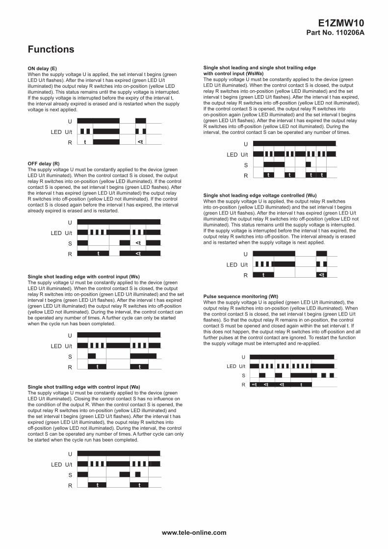
Single shot leading and single shot trailing edgewith control input (WsWa)The supply voltage U must be constantly applied to the device (green LED U/t illuminated). When the control contact S is closed, the output relay R switches into on-position (yellow LED illuminated) and the set interval t begins (green LED U/t flashes). After the interval t has expired, the output relay R switches into off-position (yellow LED not illuminated).If the control contact S is opened, the output relay R switches into on-position again (yellow LED illuminated) and the set interval t begins (green LED U/t flashes). After the interval t has expired the output relay R switches into off-position (yellow LED not illuminated). During the interval, the control contact S can be operated any number of times.
U
U/t
S
R
LED
t tt t
Single shot leading edge voltage controlled (Wu)When the supply voltage U is applied, the output relay R switches into on-position (yellow LED illuminated) and the set interval t begins (green LED U/t flashes). After the interval t has expired (green LED U/t illuminated) the output relay R switches into off-position (yellow LED not illuminated). This status remains until the supply voltage is interrupted. If the supply voltage is interrupted before the interval t has expired, the output relay R switches into off-position. The interval already is erased and is restarted when the supply voltage is next applied.
U
U/t
R
LED
<tt
Pulse sequence monitoring (Wt)When the supply voltage U is applied (green LED U/t illuminated), the output relay R switches into on-position (yellow LED illuminated). When the control contact S is closed, the set interval t begins (green LED U/t flashes). So that the output relay R remains in on-position, the control contact S must be opened and closed again within the set interval t. If this does not happen, the output relay R switches into off-position and all further pulses at the control contact are ignored. To restart the function the supply voltage must be interrupted and re-applied.
U
U/t
S
R
LED
t<t <t∞t
Functions
ON delay (E)When the supply voltage U is applied, the set interval t begins (green LED U/t flashes). After the interval t has expired (green LED U/t illuminated) the output relay R switches into on-position (yellow LED illuminated). This status remains until the supply voltage is interrupted.If the supply voltage is interrupted before the expiry of the interval t, the interval already expired is erased and is restarted when the supply voltage is next applied.
U
U/t
R
LED
<tt
OFF delay (R)The supply voltage U must be constantly applied to the device (green LED U/t illuminated). When the control contact S is closed, the output relay R switches into on-position (yellow LED illuminated). If the control contact S is opened, the set interval t begins (green LED flashes). After the interval t has expired (green LED U/t illuminated) the output relay R switches into off-position (yellow LED not illuminated). If the control contact S is closed again before the interval t has expired, the interval already expired is erased and is restarted.
U
U/t
S
R
LED
<tt
<t
Single shot leading edge with control input (Ws)The supply voltage U must be constantly applied to the device (green LED U/t illuminated). When the control contact S is closed, the output relay R switches into on-position (green LED U/t illuminated) and the set interval t begins (green LED U/t flashes). After the interval t has expired (green LED U/t illuminated) the output relay R switches into off-position (yellow LED not illuminated). During the interval, the control contact can be operated any number of times. A further cycle can only be started when the cycle run has been completed.
U
U/t
S
R
LED
tt
Single shot trailling edge with control input (Wa)The supply voltage U must be constantly applied to the device (green LED U/t illuminated). Closing the control contact S has no influence on the condition of the output R. When the control contact S is opened, the output relay R switches into on-position (yellow LED illuminated) and the set interval t begins (green LED U/t flashes). After the interval t has expired (green LED U/t illuminated), the ouput relay R switches into off-position (yellow LED not illuminated). During the interval, the control contact S can be operated any number of times. A further cycle can only be started when the cycle run has been completed.
U
U/t
S
R
LED
tt
E1ZMW10Part No. 110206A

www.tele-online.com
Dimensions
17,5mm
60mm
87m
m
44mm5mm
45m
m
Connections
A1 B1
15
A2 16 18
A1 R
15
16 18
U ~(+)
(-)
A2
SA1 B1
15
A2 16 18
A1 R
15
16 18
U ~(+)
(-)
A2
Ordering informationTypes Functions Supply voltage Part Nr. (PQ 1) Part Nr. (PQ 10)
E1ZMW10 24-240V AC/DC E, R, Ws, Wa, WsWa, Wu, Wt 24-240V AC/DC - 110206A
TELE Haase Steuergeräte Ges.m.b.H.Vorarlberger Allee 38AT-1230 Vienna, AUSTRIA
RELEASE 2017/01
Subject to alterations and errors
E1ZMW10Part No. 110206A