timing belt (3s–gte) - celicatech - powered by...
TRANSCRIPT

REMOVAL OF TIMING BELT1. DISCONNECT CABLE FROM NEGATIVE TERMINAL
OF BATTERYCAUTION: Work must be started after approx. 20seconds or longer from the time the ignition switch isturned to the ”LOCK” position and the negative (–) ter-minal cable is disconnected from the battery.
2. REMOVE RH FRONT WHEEL3. REMOVE RH ENGINE UNDER COVER4. REMOVE ALTERNATOR (See page CH–7)5. REMOVE INTERCOOLER
(See steps 13 to 15 on pages TC–9 and 10)6. REMOVE EGR VACUUM MODULATOR AND VSV
(See step 20 on page EM–121)7. REMOVE EGR VALVE AND PIPE
(See step 21 on page EM–121)8. REMOVE THROTTLE BODY
(See steps 2, 3, 5 to 8, 10 and 11 on pages FI–194 and195)
TIMING BELT (3S–GTE)COMPONENTS
–ENGINE MECHANICAL Timing Belt (3S–GTE)EM–46

13. REMOVE RH ENGINE MOUNTING BRACKETRemove the three bolts and mounting bracket.HINT: Lower the jack and perform the operation withthe engine fully down.
10. SLIGHTLY JACK UP ENGINERaise the engine enough to remove the weight from theengine mounting on the right side.
12. REMOVE RH ENGINE MOUNTING INSULATORRemove the through bolt, two nuts and mounting insula-tor.
11. REMOVE RH ENGINE MOUNTING STAYRemove the bolt, nut and mounting stay.
9. REMOVE PS DRIVE BELTLoosen the two bolts, and remove the drive belt.
–ENGINE MECHANICAL Timing Belt (3S–GTE)EM–47

18. REMOVE TIMING BELT FROM CAMSHAFT TIMINGPULLEYSHINT:
• (Re–using timing belt)Place matchmarks on the timing belt and camshafttiming pulleys, and place a matchmark on the timingbelt to match the end of the No.1 timing belt cover.
14. REMOVE CYLINDER HEAD COVER(a) Disconnect the engine wire protector between the
cylinder head cover and No.3 timing belt cover.(b) Remove the cylinder head cover.
(See step 33 on page EM–124)15. REMOVE SPARK PLUGS
(b) Check that the timing marks of the camshaft timingpulleys are aligned with the timing marks of theNo.3 timing belt cover.
If not, turn the crankshaft one revolution (360°).
17. SET NO.1 CYLINDER TO TDC/COMPRESSION(a) Turn the crankshaft pulley and align its groove with
timing mark ”0” of the No.1 timing belt cover.NOTICE: Always turn the crankshaft clockwise.
16. REMOVE NO.2 TIMING BELT COVERRemove the five screws, timing belt cover and gasket.
–ENGINE MECHANICAL Timing Belt (3S–GTE)EM–48

19. REMOVE CAMSHAFT TIMING PULLEYS(a) Hold the hexagon wrench head portion of the
camshaft with a wrench, and remove the pulleymounting bolts.
HINT (Intake camshaft timing pulley): Use SST.SST 09249–63010(b) Remove the camshaft pulleys and pins.HINT: Arrange the intake and exhaust timing pulleys.
• (When replacing timing belt tensioner only)To avoid meshing of the timing belt and timing pulley,secure one with a string. And place the matchmarks onthe timing belt and RH camshaft timing pulley.
20. REMOVE CRANKSHAFT PULLEY(a) Using SST, remove the pulley bolt.SST 09213–54015 (90119–08216) and 09330–00021
(b) Remove the timing belt from the camshaft timingpulley.
(a) Remove the two bolts and timing belt tensioner.
–ENGINE MECHANICAL Timing Belt (3S–GTE)EM–49

HINT (When re–using timing belt): After loosening thecrankshaft pulley bolt, check that the timing belt match-mark aligns with the end of the No.1 timing belt coverwhen the crankshaft pulley groove is aligned with thetiming mark ”0” of the No.1 timing belt cover. If thematchmark does not align, align as follows:
(When matchmark is out of alignment counterclockwise)
• Align the matchmark by pulling the timing belt upon the No.1 idler pulley side while turning thecrankshaft pulley clockwise.
• After aligning the matchmark, hold the timingbelt. And turn the crankshaft pulley clockwise,and align its groove with timing mark ”0” of theNo.1 timing belt cover.
(When matchmark is out of alignment clockwise)
• Align the matchmark by pulling the timing belt upon the water pump pulley side while turning thecrankshaft pulley counterclockwise.
• After aligning the matchmark, hold the timingbelt. And turn the crankshaft pulley counterclock-wise, and align its groove with timing mark ”0” ofthe N o–1 timing belt cover.
–ENGINE MECHANICAL Timing Belt (3S–GTE)EM–50

23. REMOVE TIMING BELTHINT (When re–using timing belt): Draw a directionarrow on the timing belt (in the direction of engine revo-lution), and place matchmarks on the timing belt andcrankshaft timing pulley.
(b) Using SST, remove the pulley.SST 09213–31021
HINT (When re–using timing belt): Remove the pulleywithout turning it.
21. REMOVE NO.1 TIMING BELT COVERRemove the six bolts, timing belt cover and gasket.
24. REMOVE NO.1 IDLER PULLEYRemove the pivot bolt, pulley and plate washer.
22. REMOVE TIMING BELT GUIDE
–ENGINE MECHANICAL Timing Belt (3S–GTE)EM–51

26. REMOVE CRANKSHAFT TIMING PULLEYIf the pulley cannot be removed by hand, use twoscrewdrivers.HINT: Position shop rags as shown to prevent damage.
27. REMOVE OIL PUMP PULLEYUsing SST, remove the nut and pulley.SST 09616–30011
25. REMOVE NO.2 IDLER PULLEYRemove the bolt and pulley.
–ENGINE MECHANICAL Timing Belt (3S–GTE)EM–52
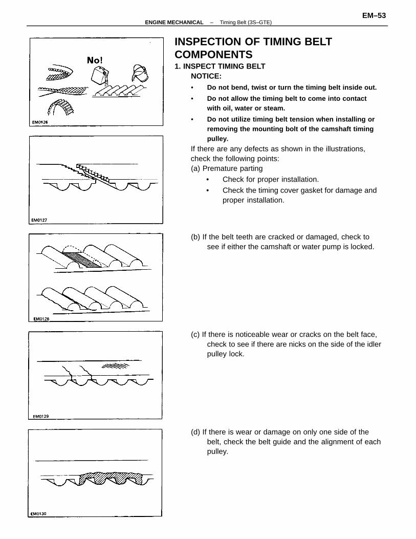
INSPECTION OF TIMING BELTCOMPONENTS1. INSPECT TIMING BELT
NOTICE:• Do not bend, twist or turn the timing belt inside out.
• Do not allow the timing belt to come into contactwith oil, water or steam.
• Do not utilize timing belt tension when installing orremoving the mounting bolt of the camshaft timingpulley.
If there are any defects as shown in the illustrations,check the following points:(a) Premature parting
• Check for proper installation.
• Check the timing cover gasket for damage andproper installation.
(d) If there is wear or damage on only one side of thebelt, check the belt guide and the alignment of eachpulley.
(c) If there is noticeable wear or cracks on the belt face,check to see if there are nicks on the side of the idlerpulley lock.
(b) If the belt teeth are cracked or damaged, check tosee if either the camshaft or water pump is locked.
–ENGINE MECHANICAL Timing Belt (3S–GTE)EM–53
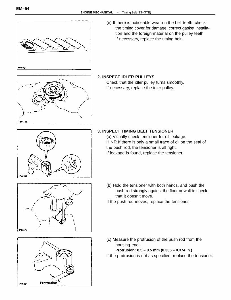
3. INSPECT TIMING BELT TENSIONER(a) Visually check tensioner for oil leakage.HINT: If there is only a small trace of oil on the seal ofthe push rod, the tensioner is all right.If leakage is found, replace the tensioner.
(c) Measure the protrusion of the push rod from thehousing end.Protrusion: 8.5 – 9.5 mm (0.335 – 0.374 in.)
If the protrusion is not as specified, replace the tensioner.
(e) If there is noticeable wear on the belt teeth, checkthe timing cover for damage, correct gasket installa-tion and the foreign material on the pulley teeth.If necessary, replace the timing belt.
(b) Hold the tensioner with both hands, and push thepush rod strongly against the floor or wall to checkthat it doesn’t move.
If the push rod moves, replace the tensioner.
2. INSPECT IDLER PULLEYSCheck that the idler pulley turns smoothly.If necessary, replace the idler pulley.
–ENGINE MECHANICAL Timing Belt (3S–GTE)EM–54
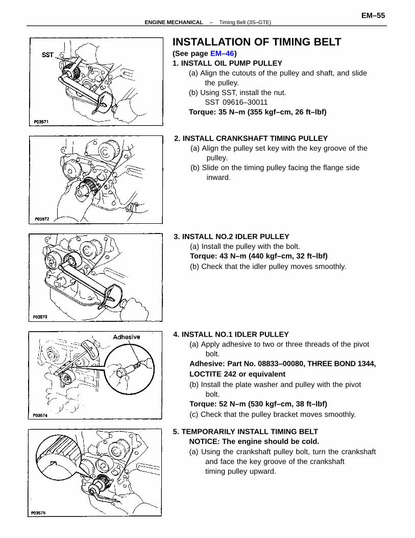
INSTALLATION OF TIMING BELT(See page EM–46)1. INSTALL OIL PUMP PULLEY
(a) Align the cutouts of the pulley and shaft, and slidethe pulley.
(b) Using SST, install the nut.SST 09616–30011
Torque: 35 N–m (355 kgf–cm, 26 ft–lbf)
4. INSTALL NO.1 IDLER PULLEY(a) Apply adhesive to two or three threads of the pivot
bolt.Adhesive: Part No. 08833–00080, T HREE BOND 1344,LOCTITE 242 or equivalent(b) Install the plate washer and pulley with the pivot
bolt.Torque: 52 N–m (530 kgf–cm, 38 ft–lbf)(c) Check that the pulley bracket moves smoothly.
5. TEMPORARILY INSTALL TIMING BELTNOTICE: The engine should be cold.(a) Using the crankshaft pulley bolt, turn the crankshaft
and face the key groove of the crankshafttiming pulley upward.
2. INSTALL CRANKSHAFT TIMING PULLEY(a) Align the pulley set key with the key groove of the
pulley.(b) Slide on the timing pulley facing the flange side
inward.
3. INSTALL NO.2 IDLER PULLEY(a) Install the pulley with the bolt.Torque: 43 N–m (440 kgf–cm, 32 ft–lbf)(b) Check that the idler pulley moves smoothly.
–ENGINE MECHANICAL Timing Belt (3S–GTE)EM–55

(b) Remove any oil or water on the crankshaft pulley, oilpump pulley, water pump pulley, No.1 idler pulleyand No.2 idler pulley, and keep them clean.
(c) Install the timing belt on the crankshaft timing pulley, oilpump pulley, No.2 idler pulley, water pumppulley and No.1 idler pulley.
HINT (when re–using timing belt) : Align the matchmarksof the crankshaft timing pulley and timing belt, andinstall the belt with the arrow pointing in the direction ofengine revolution.
6. INSTALL TIMING BELT GUIDEInstall the guide, facing the cup side outward.
8. INSTALL CRANKSHAFT PULLEY(a) Align the pulley set key with the key groove of the
pulley, and slide on the pulley.(b) Using SST, install and torque the bolt.
SST 09213–54015 (90119–08216) and 09330–00021Torque: 108 N–m (1,100 kgf–cm, 80 ft–lbf)
9. INSTALL CAMSHAFT TIMING PULLEYS(a) Using a wrench, turn and align the groove of the
camshaft with the drilled mark of the No.1 camshaftbearing cap.
7. INSTALL NO.1 TIMING BELT COVER(a) Install the gasket to the timing belt cover.(b) Install the timing belt cover with the six bolts.
–ENGINE MECHANICAL Timing Belt (3S–GTE)EM–56

(d) Hold the hexagon wrench head portion of thecamshaft with a wrench, and tighten the bolts.
Torque: 59 N–m (600 kgf–cm, 43 ft–lbf)41 N–m (420 kgf–cm, 30 ft–lbf)
HINT (intake. camshaft timing pulley):
• Use SST.SST 09249–63010
• Use a torque wrench with a fulcrum length of 340 mm(13.39 in.).
11. INSTALL TIMING BELTHINT (When re–using timing belt):
• Check that the matchmark on the timing belt matchesthe end of the No.1 timing belt cover.
If the matchmark does not align, shift the meshing of thetiming belt and crankshaft timing pulley until they align.(See page EM–50)
(b) Slide the timing pulley onto the camshaft, facingmark ”S” upward.
(c) Align the pin holes of the camshaft and timing pulley, andinsert the knock pin.
10. SET NO.1 CYLINDER TO TDC/COMPRESSION(a) Turn the crankshaft pulley, and align its groove with
timing mark ”0” of the No.1 timing belt cover.
(b) Turn the camshaft, and align the timing marks of thecamshaft timing pulleys and No.3 timing belt cover.
–ENGINE MECHANICAL Timing Belt (3S–GTE)EM–57

13. INSTALL TIMING BELT TENSIONER(a) Turn the No.1 idler pulley bolt counterclockwise to
obtain the specified torque toward the left as far asthe No.1 idler pulley will go, and temporarily installthe tensioner with the two bolts.
Torque: 18 N–m (180 kgf–cm, 13 ft–lbf)NOTICE: To apply the correct torque, apply thetorque wrench along the axis through the bolts of theNo.1 idler pulley and exhaust camshaft timing pulley.
12. SET TIMING BELT TENSIONER(a) Using a press, slowly press in the push rod using
100 –1,000 kg (220 – 2,205 Ib, 981 – 9,807 N) ofpressure.
(b) Align the holes of the push rod and housing, pass a1.27 mm hexagon wrench through the holes to keepthe setting position of the push rod.
(c) Release the press.
(a) Remove any oil or water on the camshaft timingpulley, and keep it clean.
(b) Install the timing belt, checking the tension betweenthe crankshaft timing pulley and intake camshafttiming pulley.
(b) Slowly turn the crankshaft pulley 5/6 revolution,and align its groove with the ATDC 60° mark of theNo.1 timing belt cover.
NOTICE: Always turn the crankshaft clockwise.
• Align the matchmarks of the timing belt and camshafttiming pulleys.
–ENGINE MECHANICAL Timing Belt (3S–GTE)EM–58

(c) Insert a 1.90 mm (0.075 in.) feeler gauge betweenthe tensioner body and No.1 idler pulley stopper.
(d) Turn the No.1 idler pulley bolt counterclockwise toobtain the specified torque.
Torque: 18 N–m (180 kgf–cm, 13 ft–lbf)NOTICE: To apply the correct torque, apply the torquewrench along the axis through the bolts of the No.1idler pulley and exhaust camshaft timing pulley.(e) While pushing the tensioner, alternately tighten the
two bolts.Torque: 21 N–m (210 kgf–cm, 15 ft–lbf)(f) Remove the 1.90 mm (0.075 in.) feeler gauge.(g) Remove the 1.27 mm hexagon wrench from the
tensioner.
(i) Using a feeler gauge, check the specified clearancebetween the tensioner body and No.1 idler pulleystopper.
Clearance: 1.80 – 2.20 mm (0.071 – 0.087 in.)If the clearance is not as specified, remove the tensionerand reinstall it.
14. CHECK VALVE TIMING(a) Slowly turn the crankshaft pulley two revolutions
from TDC to TDC.NOTICE: Always turn the crankshaft clockwise.
(h) Slowly turn the crankshaft pulley one revolution,and align its groove with the ATDC 60° mark oftheNo.1 timing belt cover.
NOTICE: Always turn the crankshaft clockwise.
–ENGINE MECHANICAL Timing Belt (3S–GTE)EM–59

15. INSTALL NO.2 TIMING BELT COVER(a) Install the gasket to the timing belt cover.(b) Install the belt cover with the five bolts.
16. INSTALL SPARK PLUGS (See page IG–13)Torque: 18 N–m (180 kgf–cm, 13 ft–lbf)
17. INSTALL CYLINDER HEAD COVER(a) Install the cylinder head cover.
(See step 7 on pages EM–143 and 144)(b) Install the engine wire protector between the
cylinder head cover and No.3 timing belt cover.
19. INSTALL RH ENGINE MOUNTING INSULATORInstall the mounting insulator with the through bolt andtwo nuts.Torque:Nut 52 N–m (530 kgf–cm, 38 ft–lbf)Through bolt 87 N–m (890 kgf–cm, 64 ft–lbf)
(b) Check that each pulley aligns with the timing marksas shown in the illustration.If the marks do not align, remove the timing belt andreinstall it.
18. INSTALL RH ENGINE MOUNTING BRACKETInstall the mounting bracket with the three bolts.Torque: 52 N–m (530 kgf–cm, 38 ft–lbf )
–ENGINE MECHANICAL Timing Belt (3S–GTE)EM–60
22. INSTALL THROTTLE BODY(See steps 2, 3, 5 to 8, 10 and 11 on pages FI–197 and198)
23. INSTALL EGR VALVE AND PIPE(See step 19 on page EM–145)
24. INSTALL EGR VACUUM MODULATOR AND VSV(See step 20 on page EM–146)
25. INSTALL INTERCOOLER(See steps 11 to 13 on page TC–17)
26. INSTALL ALTERNATOR (See page CH–23)27. INSTALL RH ENGINE UNDER COVER28. CONNECT CABLE TO NEGATIVE TERMINAL OF
BATTERY29. CHECK AND ADJUST DRIVE BELTS
(a) Adjust the alternator drive belt.Drive belt tension:
w/ A/C New belt 165 � 10 lbfUsed belt 84 � 15 lbf
w/o A/C New belt 150 � 25 lbfUsed belt 130 � 20 lbf
(b) Adjust the PS drive belt.Drive belt tension: New belt 125 ± 25 lbf
Used belt 80 ± 20 lbf30. INSTALL RH FRONT WHEEL
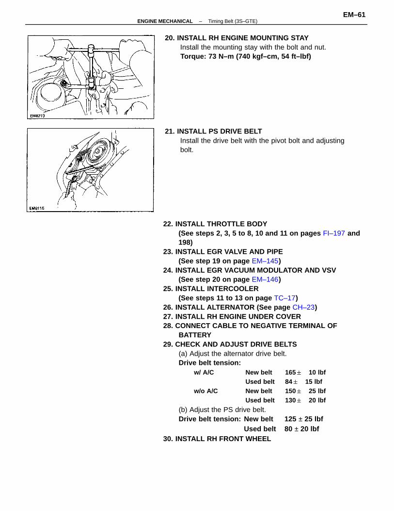
20. INSTALL RH ENGINE MOUNTING STAYInstall the mounting stay with the bolt and nut.Torque: 73 N–m (740 kgf–cm, 54 ft–lbf)
21. INSTALL PS DRIVE BELTInstall the drive belt with the pivot bolt and adjustingbolt.
–ENGINE MECHANICAL Timing Belt (3S–GTE)EM–61

ADJUSTMENT OF VALVE TIMING1. DISCONNECT CABLE FROM NEGATIVE TERMINAL
OF BATTERYCAUTION: Work must be started after approx. 20seconds or longer from the time the ignition switch isturned to the ”LOCK” position and the negative (–)terminal cable is disconnected from the battery.
2. REMOVE RH FRONT WHEEL3. REMOVE RH ENGINE UNDER COVER4. REMOVE ALTERNATOR (See page CH–7)5. REMOVE INTERCOOLER
(See steps 13 to 15 on pages TC–9 and 10)6. REMOVE SPARK PLUGS7. REMOVE NO.2 TIMING BELT COVER
(See step 16 on page EM–48)
• If there is more than one timing pulley tooth be-tween the timing marks, realign the timing marksin accordance with step 13.
• If the timing marks are aligned or the difference isless than one timing pulley tooth, proceed to step14.
8. CHECK CAMSHAFT TIMING PULLEY MARKS(a) Turn the crankshaft pulley, and align its groove with
timing mark ”0” of the No.1 timing belt cover.NOTICE: Always turn the crankshaft clockwise.
(b) Check that the timing marks of the camshaft timingpulleys are aligned with the timing mark of the No.3timing belt cover.
–ENGINE MECHANICAL Timing Belt (3S–GTE)EM–62

9. REMOVE EGR VACUUM MODULATOR AND VSV(See step 20 on page EM–121)
10. REMOVE EGR VALVE AND PIPE(See step 21 on page EM–121)
11. REMOVE THROTTLE BODY(See steps 2, 3, 5 to 8, 10 and 11 on pages FI–194 and195)
12. REMOVE CYLINDER HEAD COVER(See step 33 on page. EM–124)
(d) Reinstall the timing belt, checking the tension be-tween the crankshaft timing pulley and intakecamshaft timing pulley.
NOTICE: Install the timing belt when the engine iscold.
13. ADJUST CAMSHAFT TIMING PULLEY TIMINGMARKS(a) Remove the two bolts and timing belt tensioner.
(c) Rotate the camshaft with a wrench and align thealignment marks of the camshaft timing pulley andNo.3 timing belt cover.
(b) Remove the timing belt from the camshaft timingpulleys.
–ENGINE MECHANICAL Timing Belt (3S–GTE)EM–63

(b) Next make a note of the crankshaft pulley angle onthe No.1 timing belt cover.
HINT: Perform this check separately for the intake andexhaust sides.If the crankshaft pulley movement is within � 2.4 mm(0.094 in.) of TDC, it is correct.If it is greater than 2.4 mm (0:094 in.), go back to step 11.
14. CHECK VALVE TIMING(a) Using a wrench, turn and align the groove of the
camshaft with the drilled mark of the No.1 camshaftbearing cap.
NOTICE: Always turn the crankshaft clockwise.
(e) Install the timing belt tensioner with the two bolts.(See steps 12 and 13 on page EM–58)
Torque: 21 N–m (210 kgf–cm, 15 ft–lbf)
(f) Turn the crankshaft pulley two revolutions fromTDC to TDC.
NOTICE: Always turn the crankshaft clockwise.
(g) Check that each pulley aligns with the timing marksas shown in the illustration.
–ENGINE MECHANICAL Timing Belt (3S–GTE)EM–64

(e) Select one overlapped hole of the camshaft and timingpulley, and insert the match pin into it.
HINT:
• If there is not an overlapped hole, rotate the crankshafta little and insert the pin into the nearly overlappedhole.
• By changing the pin hole to the next one, thecrankshaft pulley angle can be adjusted by approx. 2°.
• By changing the pin hole to the next two, thecrankshaft pulley angle can be adjusted by approx. 5°.
15. ADJUST VALVE TIMING(a) Hold the hexagon wrench head portion of the
camshaft with a wrench, and remove the twocamshaft timing pulley bolts.
HINT (Intake camshaft timing pulley): Use SST.SST 09249–63010NOTICE: Do not make use of the timing belt tensionwhen loosening the pulley bolts.
(d) Turn the crankshaft pulley, and align its groove withtiming mark ”0” of the No.1 timing belt cover.
NOTICE: Always turn the crankshaft clockwise.
(b) Check that the camshaft grooves are aligned withthe drilled mark of the No.1 camshaft bearing cap.
(c) Using a magnetic finger, remove the knock pin fromthe pin hole of the camshaft timing pulley.
–ENGINE MECHANICAL Timing Belt (3S–GTE)EM–65

16. REINSTALL NO.2 TIMING BELT COVER(See step 15 on page EM–60)
17. REINSTALL SPARK PLUGS (See page IG–13)Torque: 180 kg–cm (13 ft–Ib, 18 N–m)
18. REINSTALL CYLINDER HEAD COVER(See step 7 on pages EM–143 and 144)
19. REINSTALL THROTTLE BODY(See steps 2, 3, 5 to 8, 10 and 11 on pages FI–197 and198)
20. REINSTALL EGR VALVE AND PIPE(See step 19 on page EM–145)
21. REINSTALL EGR VACUUM MODULATOR AND VSV(See step 20 on page EM–146)
22. REINSTALL INTERCOOLER(See steps 11 to 13 on page TC–17)
23. REINSTALL ALTERNATOR (See page CH–23)24. REINSTALL RH ENGINE UNDER COVER25. REINSTALL RH FRONT WHEEL26. RECONNECT CABLE TO NEGATIVE TERMINAL OF
BATTERY
(f) Hold the hexagon wrench head portion of thecamshaft with a wrench, and install the pulley bolt.
Torque: 59 N–m (600 kgf–cm, 43 ft–lbf)41 N–m (420 kgf–cm, 30 ft–lbf) for SSTHINT (Intake camshaft timing pulley):
• Use SST.SST 09249–63010
• Use a torque wrench with a fulcrum length of 340 mm(13.39 in.).
NOTICE: Do not make use of the timing belt tensionwhen tightening the bolt.(g) Turn the crankshaft clockwise two revolutions from
TDC to TDC.(h) Recheck the valve timing.
(See step 14 on page EM–64)
–ENGINE MECHANICAL Timing Belt (3S–GTE)EM–66