timken quick flex catalog
TRANSCRIPT
BA
GMin GMin
B A
A A
BB
Note gap. GMax GMax
Note gap.
BA B A
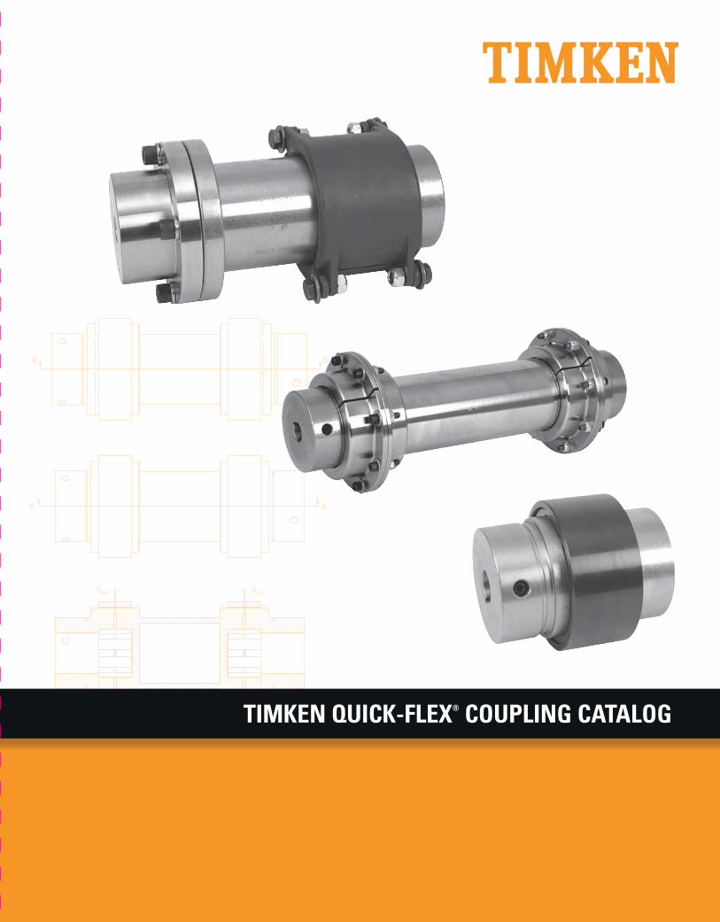
TIMKEN
® COU
PLING
CATALO
GTIMKEN QUICK-FLEX® COUPLING CATALOG
www.timken.comThe Timken team applies their know-how to improve the reliability and performance of machinery in diverse markets worldwide. The company designs, makes and markets high-performance steel as well as mechanical components, including bearings, gears, chain and related mechanical power transmission products and services.
15M
2-1
3: 2
9 O
rder
No.
105
09 U
S |
Tim
ken®
is a
regi
ster
ed tr
adem
ark
of T
he T
imke
n Co
mpa
ny.
| ©
201
3 Th
e Ti
mke
n Co
mpa
ny |
Prin
ted
in U
.S.A
.
Price: USD $75

SPHERICAL ROLLER BEARING METRIC ACCESSORIES
184 TIMKEN SPHERICAL ROLLER BEARING CATALOG
NOTES

TIMKEN
TIMKEN QUICK-FLEX® COUPLING CATALOG 1
OVERVIEW
TIMKEN QUICK-FLEX® COUPLING CATALOG INDEX
TIMKEN OVERVIEW. . . . . . . . . . . . . . . . . . . . . . . . . . . . . . . . . . . . . . . . . 2INTRODUCTION . . . . . . . . . . . . . . . . . . . . . . . . . . . . . . . . . . . . . . . . . . . . 4STORAGE OF COMPONENTS . . . . . . . . . . . . . . . . . . . . . . . . . . . . . . . . . 7
ENGINEERINGQuick-Flex Standard Bore Sizes . . . . . . . . . . . . . . . . . . . . . . . . . . . . . 10Quick-Flex Bore Tolerances and Keyway Sizes . . . . . . . . . . . . . . . . 12Torque Calculations . . . . . . . . . . . . . . . . . . . . . . . . . . . . . . . . . . . . . . . . 13Torque Ratings and Misalignment Tolerances . . . . . . . . . . . . . . . . . 14Quick-Flex Coupling Service Factors for Applications . . . . . . . . . . 19Quick-Flex Coupling Insert Chemical Compatibility . . . . . . . . . . . . . 22Installation Guides . . . . . . . . . . . . . . . . . . . . . . . . . . . . . . . . . . . . . . . . . 24
QUICK-FLEX COUPLINGSNomenclature . . . . . . . . . . . . . . . . . . . . . . . . . . . . . . . . . . . . . . . . . . . . . 38 Inserts and Covers . . . . . . . . . . . . . . . . . . . . . . . . . . . . . . . . . . . . . . . . . 40Standard Couplings . . . . . . . . . . . . . . . . . . . . . . . . . . . . . . . . . . . . . . . . 44Single-Ended Spacer Couplings . . . . . . . . . . . . . . . . . . . . . . . . . . . . . 48Double-Ended Spacer Couplings . . . . . . . . . . . . . . . . . . . . . . . . . . . . 51Bushing-Style Interchange Couplings . . . . . . . . . . . . . . . . . . . . . . . . 55Splined-Hub Couplings . . . . . . . . . . . . . . . . . . . . . . . . . . . . . . . . . . . . . 58Mill-Motor Couplings. . . . . . . . . . . . . . . . . . . . . . . . . . . . . . . . . . . . . . . 60
TIMKEN
2 TIMKEN QUICK-FLEX® COUPLING CATALOG
OVERVIEW
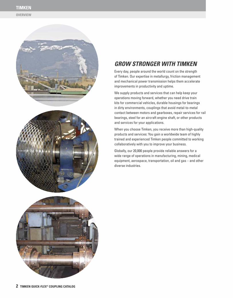
GROW STRONGER WITH TIMKENEvery day, people around the world count on the strength of Timken. Our expertise in metallurgy, friction management and mechanical power transmission helps them accelerate improvements in productivity and uptime.
We supply products and services that can help keep your operations moving forward, whether you need drive train kits for commercial vehicles, durable housings for bearings in dirty environments, couplings that avoid metal-to-metal contact between motors and gearboxes, repair services for rail bearings, steel for an aircraft engine shaft, or other products and services for your applications.
When you choose Timken, you receive more than high-quality products and services: You gain a worldwide team of highly trained and experienced Timken people committed to working collaboratively with you to improve your business.
Globally, our 20,000 people provide reliable answers for a wide range of operations in manufacturing, mining, medical equipment, aerospace, transportation, oil and gas – and other diverse industries.

TIMKEN
TIMKEN QUICK-FLEX® COUPLING CATALOG 3
OVERVIEW
INCREASE YOUR EQUIPMENT UPTIME In addition to high-quality bearings, engineered steel and mechanical power transmission components, we provide valuable integrated products and services. For example, we offer repair services and equipment monitoring equipment that can alert you to problems before they impact your uptime.
Additionally, we offer a broad selection of seals, premium lubricants, lubricators, couplings and chain to keep your operations moving smoothly.
Our 10 technology centers in the United States, Europe and Asia help pioneer tomorrow’s innovations with extensive basic and applied scientifi c research programs. Through internal development and strategic acquisition of innovative companies, we continue to expand our portfolio of highly engineered bearings, steel and components.
INTRODUCTION
4 TIMKEN QUICK-FLEX® COUPLING CATALOG
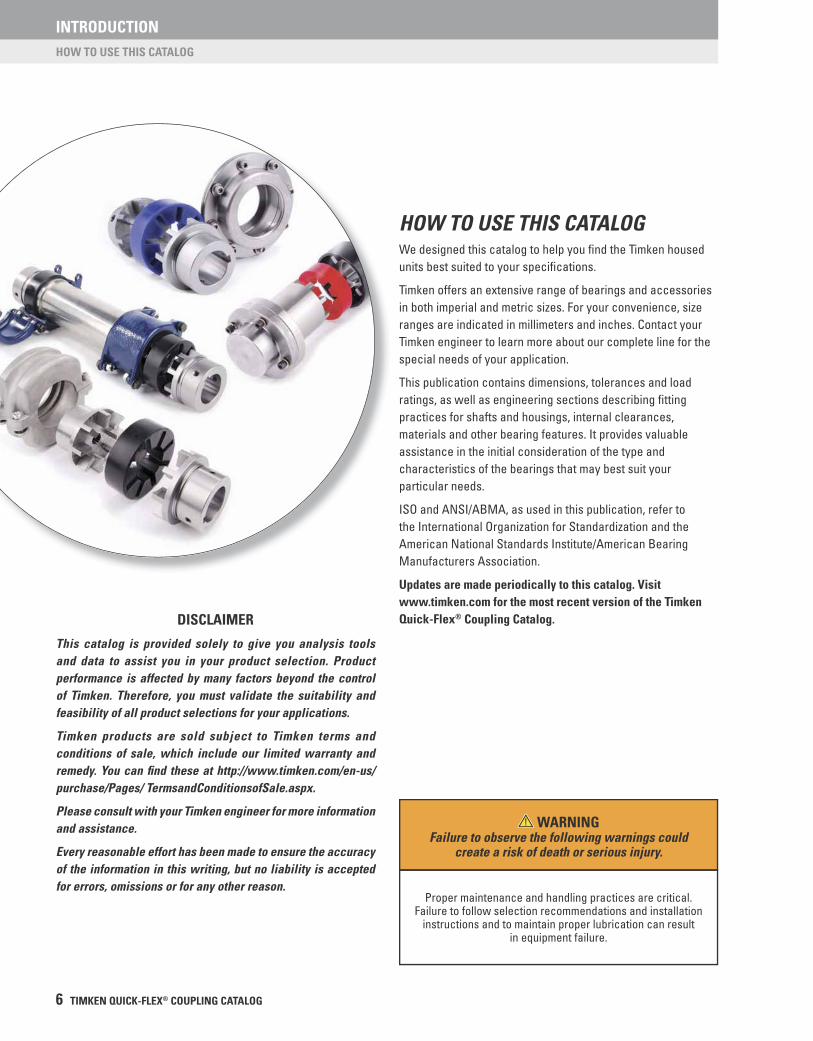
QUICK-FLEX® COUPLINGS
When your equipment operates in harsh environments, you need products you can count on, like Timken Quick-Flex® elastomeric couplings. They are durable enough to face extreme challenges, yet need minimal maintenance. They are also easy to install and require no lubrication. With a lifespan that may last as long as your equipment, overall cost of ownership remains low.
PIONEERING DESIGNTimken Quick-Flex couplings’ innovative design features two steel hubs, a polyurethane insert and a cover.
Our styles include:
• Standard couplings.
• Single-ended spacer couplings.
• Double-ended spacer couplings.
Whatever your application, you’ll fi nd a Timken coupling to suit your needs:
• Twelve families with bore ranges from 10 mm (0.37 in.) to 285 mm (11.25 in.).
• Continuous torque handling from 0.043 kNm (377 in.-lbs.) to 188.8 kNm (1,670,826 in.-lbs.).
• Able to handle temperatures from -51° C to 176° C (-60° F to 350° F).
PRODUCT ADVANTAGES
MORE UPTIMEYour hubs and shafts may remain intact when you use Timken Quick-Flex couplings. Our design helps eliminate mechanical interference between coupling hubs that can damage your equipment. As needed, you can replace the urethane insert quickly and easily without removing the hubs.
DURABILITYThere’s no metal-to-metal contact between opposing hubs with Timken Quick-Flex couplings, so you’ll save money not replacing hubs or other metal components since they do not wear. For harsh environments, including wash-downs for food processing, we offer a stainless-steel version of each coupling.
REDUCED INVENTORYThe versatility of the Timken Quick-Flex design promotes component standardization across your plant, reducing the need to stock multiple coupling styles and confi gurations.
PRODUCT FEATURES• Solid and split covers handle high speeds and torque.
• Design dampens torsional vibration and shock.
• Accepts shaft misalignment up to 2 degrees.
• Eliminates the need to move or disassemble the driving or driven equipment to replace the coupling insert.
• Versatility of design makes it a great tool for plant standardization.
• Accepts shaft sizes from 10 mm (0.37 in.) to 285 mm (11.25 in.).
• Peak handling torque from 0.085 kNm (754 in.-lbs.) to 377.5 kNm (3,341,562 in.-lbs.).
• Standard and double-ended spacer couplings available for shaft separations of 25.4 mm to 3,048 mm (1 in. to 120 in.), for increased application acceptance.
• Four bore options available to meet customers’ needs; 1) Bored, keyed and set screws style – clearance and interference fi t; 2) Bushing style; 3) Splined style; and 4) Mill-motor style.
• Stainless-steel versions available for corrosive environments.
• Four insert choices for varying torque needs and temperature ranges, up to 177° C (350° F).
• Replaces many common gear, grid and elastomeric couplings used in high- and low-torque applications to reduce plant complexity.
• Inherently balanced from precision machining for high-speed applications.
• Split-cover options help resist axial separating force under high torque.
TIMKEN QUICK-FLEX® COUPLINGS – DURABILITY FOR THE LONG HAUL
INTRODUCTION
TIMKEN QUICK-FLEX® COUPLING CATALOG 5
QUICK-FLEX® COUPLINGS
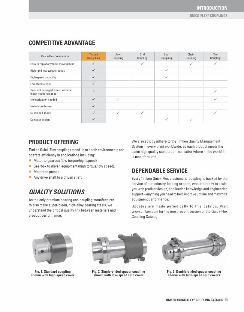
Fig. 1. Standard couplingshown with high-speed cover
Fig. 2. Single-ended spacer couplingshown with low-speed split cover
Fig. 3. Double-ended spacer couplingshown with high-speed split covers
COMPETITIVE ADVANTAGE
Quick-Flex Comparison TimkenQuick-Flex
JawCoupling
GridCoupling
GearCoupling
ChainCoupling
TireCoupling
Easy to replace without moving hubs ü ü ü ü
High- and low-torque ratings ü ü
High-speed capability ü ü
Low lifetime cost ü
Hubs not damaged when urethane insert needs replaced ü ü
No lubrication needed ü ü ü
No hub teeth wear ü
Cushioned shock ü ü ü ü
Compact design ü ü ü
PRODUCT OFFERINGTimken Quick-Flex couplings stand up to harsh environments and operate effi ciently in applications including:
• Motor to gearbox (low torque/high speed).
• Gearbox to driven equipment (high torque/low speed).
• Motors to pumps.
• Any drive shaft to a driven shaft.
QUALITY SOLUTIONSAs the only premium bearing and coupling manufacturer to also make super-clean, high-alloy bearing steels, we understand the critical quality link between materials and product performance.
We also strictly adhere to the Timken Quality Management System in every plant worldwide, so each product meets the same high quality standards – no matter where in the world it is manufactured.
DEPENDABLE SERVICEEvery Timken Quick-Flex elastomeric coupling is backed by the service of our industry-leading experts, who are ready to assist you with product design, application knowledge and engineering support – anything you need to help improve uptime and maximize equipment performance.
Updates are made periodically to this catalog. Visit www.timken.com for the most recent version of the Quick-Flex Coupling Catalog.
INTRODUCTION
6 TIMKEN QUICK-FLEX® COUPLING CATALOG
HOW TO USE THIS CATALOG
HOW TO USE THIS CATALOG We designed this catalog to help you fi nd the Timken housed units best suited to your specifi cations.
Timken offers an extensive range of bearings and accessories in both imperial and metric sizes. For your convenience, size ranges are indicated in millimeters and inches. Contact your Timken engineer to learn more about our complete line for the special needs of your application.
This publication contains dimensions, tolerances and load ratings, as well as engineering sections describing fi tting practices for shafts and housings, internal clearances, materials and other bearing features. It provides valuable assistance in the initial consideration of the type and characteristics of the bearings that may best suit your particular needs.
ISO and ANSI/ABMA, as used in this publication, refer to the International Organization for Standardization and the American National Standards Institute/American Bearing Manufacturers Association.
Updates are made periodically to this catalog. Visit www.timken.com for the most recent version of the Timken Quick-Flex® Coupling Catalog. DISCLAIMER
This catalog is provided solely to give you analysis tools and data to assist you in your product selection. Product performance is affected by many factors beyond the control of Timken. Therefore, you must validate the suitability and feasibility of all product selections for your applications.
Timken products are sold subject to Timken terms and conditions of sale, which include our limited warranty and remedy. You can fi nd these at http://www.timken.com/en-us/purchase/Pages/ TermsandConditionsofSale.aspx.
Please consult with your Timken engineer for more information and assistance.
Every reasonable effort has been made to ensure the accuracy of the information in this writing, but no liability is accepted for errors, omissions or for any other reason.
WARNINGFailure to observe the following warnings could
create a risk of death or serious injury.
Proper maintenance and handling practices are critical. Failure to follow selection recommendations and installation
instructions and to maintain proper lubrication can result in equipment failure.
TIMKEN
TIMKEN QUICK-FLEX® COUPLING CATALOG 7
STORAGE OF COMPONENTS
Timken suggests the following storage guidelines for its coupling components (hereinafter referred to as “products”):
• Unless directed otherwise by Timken, products should be kept in their original packaging until they are ready to be placed into service.
• Do not remove or alter any labels or stencil markings on the packaging.
• Products should be stored in such a way that the packaging is not pierced, crushed or otherwise damaged.
• After a product is removed from its packaging, it should be placed into service as soon as possible.
• When removing a product that is not individually packaged from a bulk pack container, the container should be resealed immediately after the product is removed.
• The relative humidity should be maintained below 60 percent and the surfaces should be dry.
• The storage area should be kept free from airborne contaminants such as, but not limited to, dust, dirt, harmful vapors, etc.
• Extreme conditions of any kind should be avoided.
Inasmuch as Timken is not familiar with a customer’s particular storage conditions, these guidelines are strongly suggested. However, the customer may very well be required by circumstance or applicable government requirements to adhere to stricter storage requirements.
Upon receipt of a product shipment, ensure that the product is not removed from its packaging until it is ready for mounting so that it does not become corroded or contaminated. Product should be stored in an appropriate atmosphere in order that it remains protected for the intended period.
Any questions concerning storage should be directed to your local sales offi ce.
STORAGE OF COMPONENTS

TIMKEN
8 TIMKEN QUICK-FLEX® COUPLING CATALOG
ENGINEERING
TIMKEN QUICK-FLEX® COUPLING CATALOG 9
ENGINEERINGThe following topics are covered within this engineering section:Quick-Flex Standard Bore Sizes . . . . . . . . . . . . . . . . . . . . . . . . . .10Quick-Flex Bore Tolerances and Keyway Sizes . . . . . . . . . . . . .12Torque Calculations . . . . . . . . . . . . . . . . . . . . . . . . . . . . . . . . . . . . .13Torque Ratings and Misalignment Tolerances . . . . . . . . . . . . . .14Quick-Flex Coupling Service Factors for Applications . . . . . . .19Quick-Flex Coupling Insert Chemical Compatibility . . . . . . . . . .22Installation Guides . . . . . . . . . . . . . . . . . . . . . . . . . . . . . . . . . . . . . .24
ENGINEERING
10 TIMKEN QUICK-FLEX® COUPLING CATALOG
QUICK-FLEX STANDARD BORE SIZES
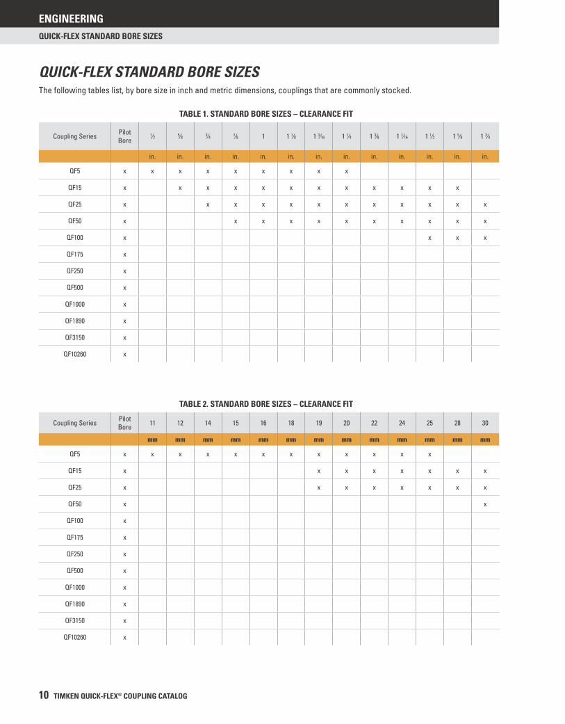
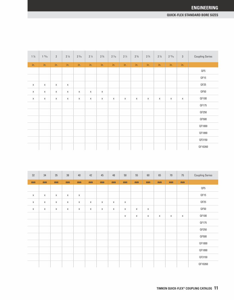
QUICK-FLEX STANDARD BORE SIZESThe following tables list, by bore size in inch and metric dimensions, couplings that are commonly stocked.
TABLE 1. STANDARD BORE SIZES – CLEARANCE FIT
Coupling Series Pilot Bore
1⁄2 5⁄8 3⁄4 7⁄8 1 1 1⁄8 1 3⁄16 1 1⁄4 1 3⁄8 1 7⁄16 1 1⁄2 1 5⁄8 1 3⁄4
in. in. in. in. in. in. in. in. in. in. in. in. in.
QF5 x x x x x x x x x
QF15 x x x x x x x x x x x x
QF25 x x x x x x x x x x x x
QF50 x x x x x x x x x x x
QF100 x x x x
QF175 x
QF250 x
QF500 x
QF1000 x
QF1890 x
QF3150 x
QF10260 x
TABLE 2. STANDARD BORE SIZES – CLEARANCE FIT
Coupling Series Pilot Bore 11 12 14 15 16 18 19 20 22 24 25 28 30
mm mm mm mm mm mm mm mm mm mm mm mm mm
QF5 x x x x x x x x x x x x
QF15 x x x x x x x x
QF25 x x x x x x x x
QF50 x x
QF100 x
QF175 x
QF250 x
QF500 x
QF1000 x
QF1890 x
QF3150 x
QF10260 x
ENGINEERING
TIMKEN QUICK-FLEX® COUPLING CATALOG 11
QUICK-FLEX STANDARD BORE SIZES
1 7⁄8 1 15⁄16 2 2 1⁄8 2 3⁄16 2 1⁄4 2 3⁄8 2 7⁄16 2 1⁄2 2 5⁄8 2 3⁄4 2 7⁄8 2 15⁄16 3 Coupling Series
in. in. in. in. in. in. in. in. in. in. in. in. in. in.
QF5
QF15
x x x x QF25
x x x x x x x QF50
x x x x x x x x x x x x x x QF100
QF175
QF250
QF500
QF1000
QF1890
QF3150
QF10260
32 34 35 38 40 42 45 48 50 55 60 65 70 75 Coupling Series
mm mm mm mm mm mm mm mm mm mm mm mm mm mm
QF5
x x x x x QF15
x x x x x x x x x QF25
x x x x x x x x x x x QF50
x x x x x x QF100
QF175
QF250
QF500
QF1000
QF1890
QF3150
QF10260
ENGINEERING
12 TIMKEN QUICK-FLEX® COUPLING CATALOG
QUICK-FLEX BORE TOLERANCES AND KEYWAY SIZES
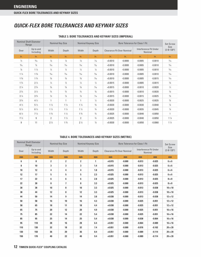
QUICK-FLEX BORE TOLERANCES AND KEYWAY SIZES
TABLE 3. BORE TOLERANCES AND KEYWAY SIZES (IMPERIAL)
Nominal Shaft Diameter Range Nominal Key Size Nominal Keyway Size Bore Tolerance for Class 1 Fit Set Screw
Size(2 @ 120°)Over Up to and
Including Width Depth Width Depth Clearance Fit Over Nominal Interference Fit Under Nominal
in. in. in. in. in. in. in. in. in. in. in.1⁄2 9⁄16 1⁄8 1⁄8 1⁄8 1⁄16 +0.0010 -0.0000 -0.0005 -0.0010 5⁄16
9⁄16 7⁄8 3⁄16 3⁄16 3⁄16 3⁄32 +0.0010 -0.0000 -0.0005 -0.0010 5⁄16
7⁄8 1 1⁄4 1⁄4 1⁄4 1⁄4 1⁄8 +0.0010 -0.0000 -0.0005 -0.0010 5⁄16
1 1⁄4 1 3⁄8 5⁄16 5⁄16 5⁄16 5⁄32 +0.0010 -0.0000 -0.0005 -0.0010 5⁄16
1 3⁄8 1 3⁄4 3⁄8 3⁄8 3⁄8 3⁄16 +0.0010 -0.0000 -0.0005 -0.0015 5⁄16
1 3⁄4 2 1⁄4 1⁄2 1⁄2 1⁄2 1⁄4 +0.0015 -0.0000 -0.0005 -0.0015 3⁄8
2 1⁄4 2 3⁄4 5⁄8 5⁄8 5⁄8 5⁄16 +0.0015 -0.0000 -0.0010 -0.0020 1⁄2
2 3⁄4 3 1⁄4 3⁄4 3⁄4 3⁄4 3⁄8 +0.0015 -0.0000 -0.0010 -0.0020 5⁄8
3 1⁄4 3 3⁄4 7⁄8 7⁄8 7⁄8 7⁄16 +0.0015 -0.0000 -0.0015 -0.0025 5⁄8
3 3⁄4 4 1⁄2 1 1 1 1⁄2 +0.0020 -0.0000 -0.0025 -0.0035 5⁄8
4 1⁄2 5 1⁄2 1 1⁄4 1 1⁄4 1 1⁄4 5⁄8 +0.0020 -0.0000 -0.0030 -0.0040 7⁄8
5 1⁄2 6 1⁄2 1 1⁄2 1 1⁄2 1 1⁄2 3⁄4 +0.0020 -0.0000 -0.0035 -0.0045 7⁄8
6 1⁄2 7 1⁄2 1 3⁄4 1 1⁄2 1 3⁄4 3⁄4 +0.0025 -0.0000 -0.0040 -0.0050 1
7 1⁄2 9 2 1 1⁄2 2 3⁄4 +0.0025 -0.0000 -0.0040 -0.0050 1 1⁄4
9 11 2 1⁄2 1 3⁄4 2 1⁄2 7⁄8 +0.0030 -0.0000 -0.0050 -0.0060 1 1⁄4
TABLE 4. BORE TOLERANCES AND KEYWAY SIZES (METRIC)
Nominal Shaft Diameter Range Nominal Key Size Nominal Keyway Size Bore Tolerance for Class 1 Fit Set Screw
Size(2 @ 120°)Over Up to and
Including Width Depth Width Depth Clearance Fit Over Nominal Interference Fit Under Nominal
mm mm mm mm mm mm mm mm mm mm mm
6 8 2 2 2 1 +0.015 -0.000 -0.013 -0.025 6 x 6
8 10 3 3 3 1.4 +0.015 -0.000 -0.013 -0.025 6 x 6
10 12 4 4 4 1.8 +0.015 -0.000 -0.013 -0.025 6 x 6
12 17 5 5 5 2.3 +0.025 -0.000 -0.013 -0.025 6 x 6
17 22 6 6 6 2.8 +0.025 -0.000 -0.013 -0.025 8 x 8
22 30 8 7 8 3.3 +0.025 -0.000 -0.013 -0.025 8 x 8
30 38 10 8 10 3.3 +0.025 -0.000 -0.013 -0.038 10 x 10
38 44 12 8 12 3.3 +0.025 -0.000 -0.013 -0.038 10 x 10
44 50 14 9 14 3.8 +0.038 -0.000 -0.013 -0.038 12 x 12
50 58 16 10 16 4.3 +0.038 -0.000 -0.025 -0.051 12 x 12
58 65 18 11 18 4.4 +0.038 -0.000 -0.025 -0.051 12 x 12
65 75 20 12 20 4.9 +0.038 -0.000 -0.025 -0.051 16 x 16
75 85 22 14 22 5.4 +0.038 -0.000 -0.025 -0.051 16 x 16
85 95 25 14 25 5.4 +0.038 -0.000 -0.038 -0.064 16 x 16
95 110 28 16 28 6.4 +0.051 -0.000 -0.064 -0.089 16 x 16
110 130 32 18 32 7.4 +0.051 -0.000 -0.076 -0.102 20 x 20
130 150 36 20 36 8.4 +0.051 -0.000 -0.089 -0.114 20 x 20
150 170 40 22 40 9.4 +0.051 -0.000 -0.089 -0.114 20 x 20
ENGINEERING
TIMKEN QUICK-FLEX® COUPLING CATALOG 13
TORQUE CALCULATION
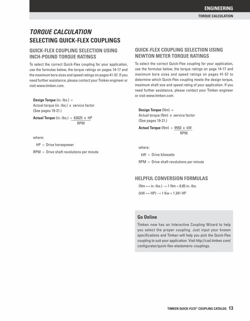
SELECTING QUICK-FLEX COUPLINGS
QUICK-FLEX COUPLING SELECTION USING INCH-POUND TORQUE RATINGSTo select the correct Quick-Flex coupling for your application, use the formulas below, the torque ratings on pages 14-17 and the maximum bore sizes and speed ratings on pages 41-57. If you need further assistance, please contact your Timken engineer or visit www.timken.com.
Design Torque (in.-lbs.) = Actual torque (in.-lbs.) x service factor (See pages 19-21.)
Actual Torque (in.-lbs.) = 63025 x HP ___________ RPM
where:
HP = Drive horsepower
RPM = Drive shaft revolutions per minute
Go OnlineTimken now has an Interactive Coupling Wizard to help you select the proper coupling. Just input your known specifi cations and Timken will help you pick the Quick-Flex coupling to suit your application. Visit http://cad.timken.com/confi gurator/quick-fl ex-elastomeric-couplings.
QUICK-FLEX COUPLING SELECTION USING NEWTON METER TORQUE RATINGSTo select the correct Quick-Flex coupling for your application, use the formulas below, the torque ratings on page 14-17 and maximum bore sizes and speed ratings on pages 41-57 to determine which Quick-Flex coupling meets the design torque, maximum shaft size and speed rating of your application. If you need further assistance, please contact your Timken engineer or visit www.timken.com.
Design Torque (Nm) = Actual torque (Nm) x service factor (See pages 19-21.)
Actual Torque (Nm) = 9550 x kW __________ RPM
where:
kW = Drive kilowatts
RPM = Drive shaft revolutions per minute
HELPFUL CONVERSION FORMULAS (Nm ↔ in.-lbs.) → 1 Nm = 8.85 in.-lbs.
(kW ↔ HP) → 1 Kw = 1.341 HP
TORQUE CALCULATION
ENGINEERING
14 TIMKEN QUICK-FLEX® COUPLING CATALOG
TORQUE RATINGS AND MISALIGNMENT TOLERANCES
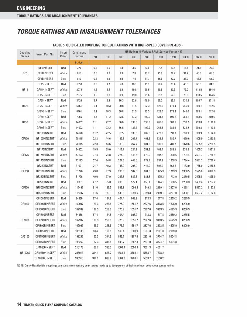
TORQUE RATINGS AND MISALIGNMENT TOLERANCES
TABLE 5. QUICK-FLEX COUPLING TORQUE RATINGS WITH HIGH-SPEED COVER (IN.-LBS.)
Coupling Series Insert Part No. Insert
ColorContinuous
TorqueHP Ratings @ Various RPM (Service Factor = 1)
50 100 300 600 900 1200 1750 2400 3600 5000
in.-lbs.
QF5
QF5INSERT Red 377 0.3 0.6 1.8 3.6 5.4 7.2 10.5 14.4 21.5 29.9
QF5HINSERT White 819 0.6 1.3 3.9 7.8 11.7 15.6 22.7 31.2 46.8 65.0
QF5BINSERT Blue 819 0.6 1.3 3.9 7.8 11.7 15.6 22.7 31.2 46.8 65.0
QF15
QF15INSERT Red 1059 0.8 1.7 5.0 10.1 15.1 20.2 29.4 40.3 60.5 84.0
QF15HINSERT White 2075 1.6 3.3 9.9 19.8 29.6 39.5 57.6 79.0 118.5 164.6
QF15BINSERT Blue 2075 1.6 3.3 9.9 19.8 29.6 39.5 57.6 79.0 118.5 164.6
QF25
QF25INSERT Red 3426 2.7 5.4 16.3 32.6 48.9 65.2 95.1 130.5 195.7 271.8
QF25HINSERT White 6461 5.1 10.3 30.8 61.5 92.3 123.0 179.4 246.0 369.1 512.6
QF25BINSERT Blue 6461 5.1 10.3 30.8 61.5 92.3 123.0 179.4 246.0 369.1 512.6
QF50
QF50INSERT Red 7066 5.6 11.2 33.6 67.3 100.9 134.5 196.2 269.1 403.6 560.6
QF50HINSERT White 14002 11.1 22.2 66.6 133.3 199.9 266.6 388.8 533.2 799.8 1110.8
QF50BINSERT Blue 14002 11.1 22.2 66.6 133.3 199.9 266.6 388.8 533.2 799.8 1110.8
QF100
QF100INSERT Red 14178 11.2 22.5 67.5 135.0 202.5 270.0 393.7 539.9 809.9 1124.8
QF100HINSERT White 28115 22.3 44.6 133.8 267.7 401.5 535.3 780.7 1070.6 1605.9 2230.5
QF100BINSERT Blue 28115 22.3 44.6 133.8 267.7 401.5 535.3 780.7 1070.6 1605.9 2230.5
QF175
QF175INSERT Red 24602 19.5 39.0 117.1 234.2 351.3 468.4 683.1 936.8 1405.3 1951.8
QF175HINSERT White 47123 37.4 74.8 224.3 448.6 672.9 897.2 1308.5 1794.4 2691.7 3738.4
QF175BINSERT Blue 47123 37.4 74.8 224.3 448.6 672.9 897.2 1308.5 1794.4 2691.7 3738.4
QF250
QF250INSERT Red 31091 24.7 49.3 148.0 296.0 444.0 592.0 863.3 1183.9 1775.9 2466.6
QF250HINSERT White 61726 49.0 97.9 293.8 587.6 881.5 1175.3 1713.9 2350.5 3525.8 4896.9
QF250BINSERT Blue 61726 49.0 97.9 293.8 587.6 881.5 1175.3 1713.9 2350.5 3525.8 4896.9
QF500
QF500INSERT Red 60091 47.7 95.3 286.0 572.1 858.1 1144.1 1668.5 2288.3 3432.4 4767.2
QF500HINSERT White 115497 91.6 183.3 549.8 1099.5 1649.3 2199.1 3207.0 4398.1 6597.2 9162.8
QF500BINSERT Blue 115497 91.6 183.3 549.8 1099.5 1649.3 2199.1 3207.0 4398.1 6597.2 9162.8
QF1000
QF1000INSERT Red 84966 67.4 134.8 404.4 808.9 1213.3 1617.8 2359.2 3235.5
QF1000HINSERT White 162997 129.3 258.6 775.9 1551.7 2327.6 3103.5 4525.9 6206.9
QF1000BINSERT Blue 162997 129.3 258.6 775.9 1551.7 2327.6 3103.5 4525.9 6206.9
QF1890
QF1890INSERT Red 84966 67.4 134.8 404.4 808.9 1213.3 1617.8 2359.2 3235.5
QF1890HINSERT White 162997 129.3 258.6 775.9 1551.7 2327.6 3103.5 4525.9 6206.9
QF1890BINSERT Blue 162997 129.3 258.6 775.9 1551.7 2327.6 3103.5 4525.9 6206.9
QF3150
QF3150INSERT Red 105135 83.4 166.8 500.4 1000.9 1501.3 2001.8 2919.3
QF3150HINSERT White 198252 157.3 314.6 943.7 1887.4 2831.0 3774.7 5504.8
QF3150BINSERT Blue 198252 157.3 314.6 943.7 1887.4 2831.0 3774.7 5504.8
QF10260
QF10260INSERT Red 210173 166.7 333.5 1000.4 2000.9 3001.3 4001.7
QF10260HINSERT White 395913 314.1 628.2 1884.6 3769.1 5653.7 7538.2
QF10260BINSERT Blue 395913 314.1 628.2 1884.6 3769.1 5653.7 7538.2
NOTE: Quick-Flex fl exible couplings can sustain momentary peak torque loads up to 200 percent of their maximum continuous torque rating.
ENGINEERING
TIMKEN QUICK-FLEX® COUPLING CATALOG 15
TORQUE RATINGS AND MISALIGNMENT TOLERANCES
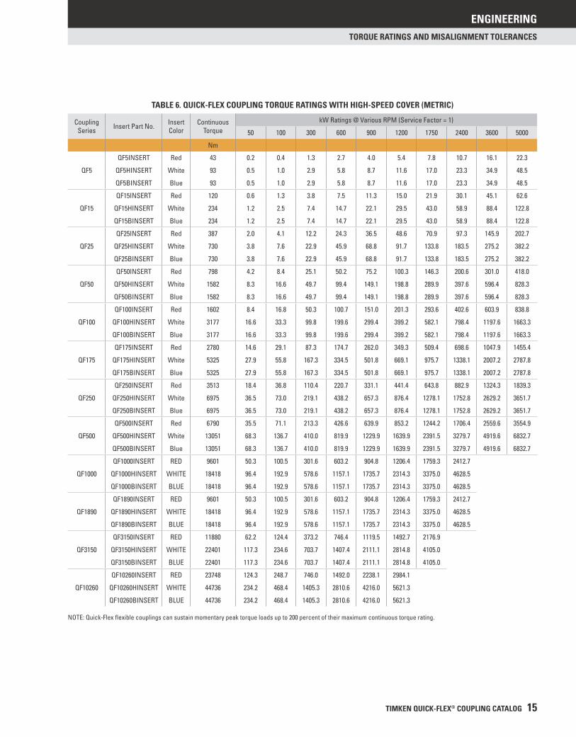
TABLE 6. QUICK-FLEX COUPLING TORQUE RATINGS WITH HIGH-SPEED COVER (METRIC)
Coupling Series Insert Part No. Insert
ColorContinuous
TorquekW Ratings @ Various RPM (Service Factor = 1)
50 100 300 600 900 1200 1750 2400 3600 5000
Nm
QF5
QF5INSERT Red 43 0.2 0.4 1.3 2.7 4.0 5.4 7.8 10.7 16.1 22.3
QF5HINSERT White 93 0.5 1.0 2.9 5.8 8.7 11.6 17.0 23.3 34.9 48.5
QF5BINSERT Blue 93 0.5 1.0 2.9 5.8 8.7 11.6 17.0 23.3 34.9 48.5
QF15
QF15INSERT Red 120 0.6 1.3 3.8 7.5 11.3 15.0 21.9 30.1 45.1 62.6
QF15HINSERT White 234 1.2 2.5 7.4 14.7 22.1 29.5 43.0 58.9 88.4 122.8
QF15BINSERT Blue 234 1.2 2.5 7.4 14.7 22.1 29.5 43.0 58.9 88.4 122.8
QF25
QF25INSERT Red 387 2.0 4.1 12.2 24.3 36.5 48.6 70.9 97.3 145.9 202.7
QF25HINSERT White 730 3.8 7.6 22.9 45.9 68.8 91.7 133.8 183.5 275.2 382.2
QF25BINSERT Blue 730 3.8 7.6 22.9 45.9 68.8 91.7 133.8 183.5 275.2 382.2
QF50
QF50INSERT Red 798 4.2 8.4 25.1 50.2 75.2 100.3 146.3 200.6 301.0 418.0
QF50HINSERT White 1582 8.3 16.6 49.7 99.4 149.1 198.8 289.9 397.6 596.4 828.3
QF50BINSERT Blue 1582 8.3 16.6 49.7 99.4 149.1 198.8 289.9 397.6 596.4 828.3
QF100
QF100INSERT Red 1602 8.4 16.8 50.3 100.7 151.0 201.3 293.6 402.6 603.9 838.8
QF100HINSERT White 3177 16.6 33.3 99.8 199.6 299.4 399.2 582.1 798.4 1197.6 1663.3
QF100BINSERT Blue 3177 16.6 33.3 99.8 199.6 299.4 399.2 582.1 798.4 1197.6 1663.3
QF175
QF175INSERT Red 2780 14.6 29.1 87.3 174.7 262.0 349.3 509.4 698.6 1047.9 1455.4
QF175HINSERT White 5325 27.9 55.8 167.3 334.5 501.8 669.1 975.7 1338.1 2007.2 2787.8
QF175BINSERT Blue 5325 27.9 55.8 167.3 334.5 501.8 669.1 975.7 1338.1 2007.2 2787.8
QF250
QF250INSERT Red 3513 18.4 36.8 110.4 220.7 331.1 441.4 643.8 882.9 1324.3 1839.3
QF250HINSERT White 6975 36.5 73.0 219.1 438.2 657.3 876.4 1278.1 1752.8 2629.2 3651.7
QF250BINSERT Blue 6975 36.5 73.0 219.1 438.2 657.3 876.4 1278.1 1752.8 2629.2 3651.7
QF500
QF500INSERT Red 6790 35.5 71.1 213.3 426.6 639.9 853.2 1244.2 1706.4 2559.6 3554.9
QF500HINSERT White 13051 68.3 136.7 410.0 819.9 1229.9 1639.9 2391.5 3279.7 4919.6 6832.7
QF500BINSERT Blue 13051 68.3 136.7 410.0 819.9 1229.9 1639.9 2391.5 3279.7 4919.6 6832.7
QF1000
QF1000INSERT RED 9601 50.3 100.5 301.6 603.2 904.8 1206.4 1759.3 2412.7
QF1000HINSERT WHITE 18418 96.4 192.9 578.6 1157.1 1735.7 2314.3 3375.0 4628.5
QF1000BINSERT BLUE 18418 96.4 192.9 578.6 1157.1 1735.7 2314.3 3375.0 4628.5
QF1890
QF1890INSERT RED 9601 50.3 100.5 301.6 603.2 904.8 1206.4 1759.3 2412.7
QF1890HINSERT WHITE 18418 96.4 192.9 578.6 1157.1 1735.7 2314.3 3375.0 4628.5
QF1890BINSERT BLUE 18418 96.4 192.9 578.6 1157.1 1735.7 2314.3 3375.0 4628.5
QF3150
QF3150INSERT RED 11880 62.2 124.4 373.2 746.4 1119.5 1492.7 2176.9
QF3150HINSERT WHITE 22401 117.3 234.6 703.7 1407.4 2111.1 2814.8 4105.0
QF3150BINSERT BLUE 22401 117.3 234.6 703.7 1407.4 2111.1 2814.8 4105.0
QF10260
QF10260INSERT RED 23748 124.3 248.7 746.0 1492.0 2238.1 2984.1
QF10260HINSERT WHITE 44736 234.2 468.4 1405.3 2810.6 4216.0 5621.3
QF10260BINSERT BLUE 44736 234.2 468.4 1405.3 2810.6 4216.0 5621.3
NOTE: Quick-Flex fl exible couplings can sustain momentary peak torque loads up to 200 percent of their maximum continuous torque rating.
ENGINEERING
16 TIMKEN QUICK-FLEX® COUPLING CATALOG
TORQUE RATINGS AND MISALIGNMENT TOLERANCES
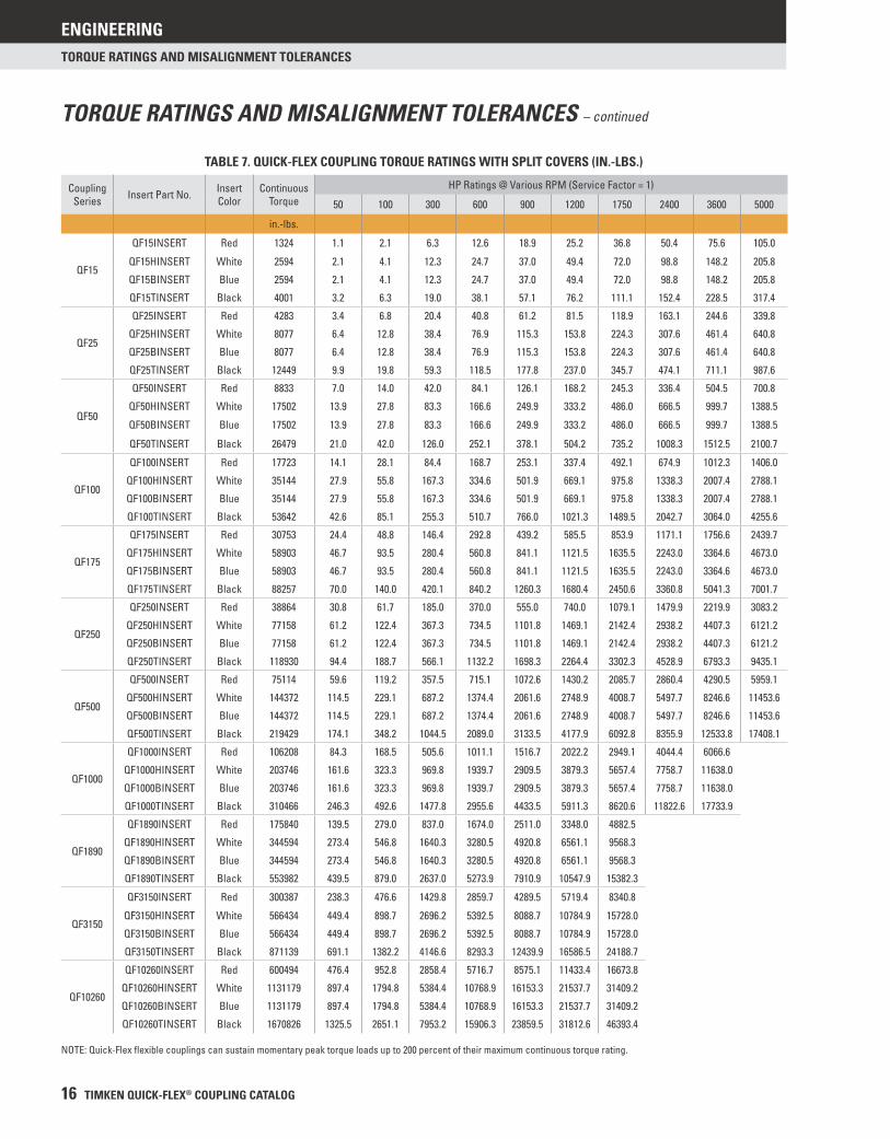
TABLE 7. QUICK-FLEX COUPLING TORQUE RATINGS WITH SPLIT COVERS (IN.-LBS.)
Coupling Series Insert Part No. Insert
ColorContinuous
TorqueHP Ratings @ Various RPM (Service Factor = 1)
50 100 300 600 900 1200 1750 2400 3600 5000
in.-lbs.
QF15
QF15INSERT Red 1324 1.1 2.1 6.3 12.6 18.9 25.2 36.8 50.4 75.6 105.0
QF15HINSERT White 2594 2.1 4.1 12.3 24.7 37.0 49.4 72.0 98.8 148.2 205.8
QF15BINSERT Blue 2594 2.1 4.1 12.3 24.7 37.0 49.4 72.0 98.8 148.2 205.8
QF15TINSERT Black 4001 3.2 6.3 19.0 38.1 57.1 76.2 111.1 152.4 228.5 317.4
QF25
QF25INSERT Red 4283 3.4 6.8 20.4 40.8 61.2 81.5 118.9 163.1 244.6 339.8
QF25HINSERT White 8077 6.4 12.8 38.4 76.9 115.3 153.8 224.3 307.6 461.4 640.8
QF25BINSERT Blue 8077 6.4 12.8 38.4 76.9 115.3 153.8 224.3 307.6 461.4 640.8
QF25TINSERT Black 12449 9.9 19.8 59.3 118.5 177.8 237.0 345.7 474.1 711.1 987.6
QF50
QF50INSERT Red 8833 7.0 14.0 42.0 84.1 126.1 168.2 245.3 336.4 504.5 700.8
QF50HINSERT White 17502 13.9 27.8 83.3 166.6 249.9 333.2 486.0 666.5 999.7 1388.5
QF50BINSERT Blue 17502 13.9 27.8 83.3 166.6 249.9 333.2 486.0 666.5 999.7 1388.5
QF50TINSERT Black 26479 21.0 42.0 126.0 252.1 378.1 504.2 735.2 1008.3 1512.5 2100.7
QF100
QF100INSERT Red 17723 14.1 28.1 84.4 168.7 253.1 337.4 492.1 674.9 1012.3 1406.0
QF100HINSERT White 35144 27.9 55.8 167.3 334.6 501.9 669.1 975.8 1338.3 2007.4 2788.1
QF100BINSERT Blue 35144 27.9 55.8 167.3 334.6 501.9 669.1 975.8 1338.3 2007.4 2788.1
QF100TINSERT Black 53642 42.6 85.1 255.3 510.7 766.0 1021.3 1489.5 2042.7 3064.0 4255.6
QF175
QF175INSERT Red 30753 24.4 48.8 146.4 292.8 439.2 585.5 853.9 1171.1 1756.6 2439.7
QF175HINSERT White 58903 46.7 93.5 280.4 560.8 841.1 1121.5 1635.5 2243.0 3364.6 4673.0
QF175BINSERT Blue 58903 46.7 93.5 280.4 560.8 841.1 1121.5 1635.5 2243.0 3364.6 4673.0
QF175TINSERT Black 88257 70.0 140.0 420.1 840.2 1260.3 1680.4 2450.6 3360.8 5041.3 7001.7
QF250
QF250INSERT Red 38864 30.8 61.7 185.0 370.0 555.0 740.0 1079.1 1479.9 2219.9 3083.2
QF250HINSERT White 77158 61.2 122.4 367.3 734.5 1101.8 1469.1 2142.4 2938.2 4407.3 6121.2
QF250BINSERT Blue 77158 61.2 122.4 367.3 734.5 1101.8 1469.1 2142.4 2938.2 4407.3 6121.2
QF250TINSERT Black 118930 94.4 188.7 566.1 1132.2 1698.3 2264.4 3302.3 4528.9 6793.3 9435.1
QF500
QF500INSERT Red 75114 59.6 119.2 357.5 715.1 1072.6 1430.2 2085.7 2860.4 4290.5 5959.1
QF500HINSERT White 144372 114.5 229.1 687.2 1374.4 2061.6 2748.9 4008.7 5497.7 8246.6 11453.6
QF500BINSERT Blue 144372 114.5 229.1 687.2 1374.4 2061.6 2748.9 4008.7 5497.7 8246.6 11453.6
QF500TINSERT Black 219429 174.1 348.2 1044.5 2089.0 3133.5 4177.9 6092.8 8355.9 12533.8 17408.1
QF1000
QF1000INSERT Red 106208 84.3 168.5 505.6 1011.1 1516.7 2022.2 2949.1 4044.4 6066.6
QF1000HINSERT White 203746 161.6 323.3 969.8 1939.7 2909.5 3879.3 5657.4 7758.7 11638.0
QF1000BINSERT Blue 203746 161.6 323.3 969.8 1939.7 2909.5 3879.3 5657.4 7758.7 11638.0
QF1000TINSERT Black 310466 246.3 492.6 1477.8 2955.6 4433.5 5911.3 8620.6 11822.6 17733.9
QF1890
QF1890INSERT Red 175840 139.5 279.0 837.0 1674.0 2511.0 3348.0 4882.5
QF1890HINSERT White 344594 273.4 546.8 1640.3 3280.5 4920.8 6561.1 9568.3
QF1890BINSERT Blue 344594 273.4 546.8 1640.3 3280.5 4920.8 6561.1 9568.3
QF1890TINSERT Black 553982 439.5 879.0 2637.0 5273.9 7910.9 10547.9 15382.3
QF3150
QF3150INSERT Red 300387 238.3 476.6 1429.8 2859.7 4289.5 5719.4 8340.8
QF3150HINSERT White 566434 449.4 898.7 2696.2 5392.5 8088.7 10784.9 15728.0
QF3150BINSERT Blue 566434 449.4 898.7 2696.2 5392.5 8088.7 10784.9 15728.0
QF3150TINSERT Black 871139 691.1 1382.2 4146.6 8293.3 12439.9 16586.5 24188.7
QF10260
QF10260INSERT Red 600494 476.4 952.8 2858.4 5716.7 8575.1 11433.4 16673.8
QF10260HINSERT White 1131179 897.4 1794.8 5384.4 10768.9 16153.3 21537.7 31409.2
QF10260BINSERT Blue 1131179 897.4 1794.8 5384.4 10768.9 16153.3 21537.7 31409.2
QF10260TINSERT Black 1670826 1325.5 2651.1 7953.2 15906.3 23859.5 31812.6 46393.4
NOTE: Quick-Flex fl exible couplings can sustain momentary peak torque loads up to 200 percent of their maximum continuous torque rating.
TORQUE RATINGS AND MISALIGNMENT TOLERANCES – continued
ENGINEERING
TIMKEN QUICK-FLEX® COUPLING CATALOG 17
TORQUE RATINGS AND MISALIGNMENT TOLERANCES
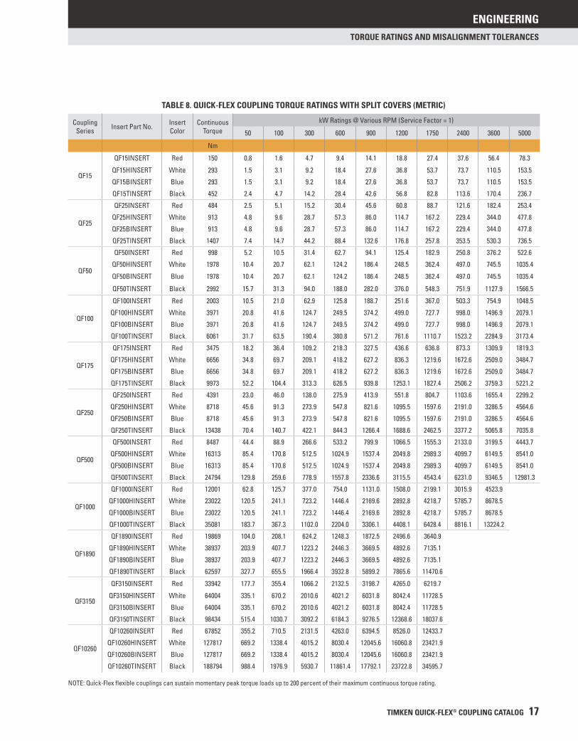
TABLE 8. QUICK-FLEX COUPLING TORQUE RATINGS WITH SPLIT COVERS (METRIC)
Coupling Series Insert Part No. Insert
ColorContinuous
TorquekW Ratings @ Various RPM (Service Factor = 1)
50 100 300 600 900 1200 1750 2400 3600 5000
Nm
QF15
QF15INSERT Red 150 0.8 1.6 4.7 9.4 14.1 18.8 27.4 37.6 56.4 78.3
QF15HINSERT White 293 1.5 3.1 9.2 18.4 27.6 36.8 53.7 73.7 110.5 153.5
QF15BINSERT Blue 293 1.5 3.1 9.2 18.4 27.6 36.8 53.7 73.7 110.5 153.5
QF15TINSERT Black 452 2.4 4.7 14.2 28.4 42.6 56.8 82.8 113.6 170.4 236.7
QF25
QF25INSERT Red 484 2.5 5.1 15.2 30.4 45.6 60.8 88.7 121.6 182.4 253.4
QF25HINSERT White 913 4.8 9.6 28.7 57.3 86.0 114.7 167.2 229.4 344.0 477.8
QF25BINSERT Blue 913 4.8 9.6 28.7 57.3 86.0 114.7 167.2 229.4 344.0 477.8
QF25TINSERT Black 1407 7.4 14.7 44.2 88.4 132.6 176.8 257.8 353.5 530.3 736.5
QF50
QF50INSERT Red 998 5.2 10.5 31.4 62.7 94.1 125.4 182.9 250.8 376.2 522.6
QF50HINSERT White 1978 10.4 20.7 62.1 124.2 186.4 248.5 362.4 497.0 745.5 1035.4
QF50BINSERT Blue 1978 10.4 20.7 62.1 124.2 186.4 248.5 362.4 497.0 745.5 1035.4
QF50TINSERT Black 2992 15.7 31.3 94.0 188.0 282.0 376.0 548.3 751.9 1127.9 1566.5
QF100
QF100INSERT Red 2003 10.5 21.0 62.9 125.8 188.7 251.6 367.0 503.3 754.9 1048.5
QF100HINSERT White 3971 20.8 41.6 124.7 249.5 374.2 499.0 727.7 998.0 1496.9 2079.1
QF100BINSERT Blue 3971 20.8 41.6 124.7 249.5 374.2 499.0 727.7 998.0 1496.9 2079.1
QF100TINSERT Black 6061 31.7 63.5 190.4 380.8 571.2 761.6 1110.7 1523.2 2284.9 3173.4
QF175
QF175INSERT Red 3475 18.2 36.4 109.2 218.3 327.5 436.6 636.8 873.3 1309.9 1819.3
QF175HINSERT White 6656 34.8 69.7 209.1 418.2 627.2 836.3 1219.6 1672.6 2509.0 3484.7
QF175BINSERT Blue 6656 34.8 69.7 209.1 418.2 627.2 836.3 1219.6 1672.6 2509.0 3484.7
QF175TINSERT Black 9973 52.2 104.4 313.3 626.5 939.8 1253.1 1827.4 2506.2 3759.3 5221.2
QF250
QF250INSERT Red 4391 23.0 46.0 138.0 275.9 413.9 551.8 804.7 1103.6 1655.4 2299.2
QF250HINSERT White 8718 45.6 91.3 273.9 547.8 821.6 1095.5 1597.6 2191.0 3286.5 4564.6
QF250BINSERT Blue 8718 45.6 91.3 273.9 547.8 821.6 1095.5 1597.6 2191.0 3286.5 4564.6
QF250TINSERT Black 13438 70.4 140.7 422.1 844.3 1266.4 1688.6 2462.5 3377.2 5065.8 7035.8
QF500
QF500INSERT Red 8487 44.4 88.9 266.6 533.2 799.9 1066.5 1555.3 2133.0 3199.5 4443.7
QF500HINSERT White 16313 85.4 170.8 512.5 1024.9 1537.4 2049.8 2989.3 4099.7 6149.5 8541.0
QF500BINSERT Blue 16313 85.4 170.8 512.5 1024.9 1537.4 2049.8 2989.3 4099.7 6149.5 8541.0
QF500TINSERT Black 24794 129.8 259.6 778.9 1557.8 2336.6 3115.5 4543.4 6231.0 9346.5 12981.3
QF1000
QF1000INSERT Red 12001 62.8 125.7 377.0 754.0 1131.0 1508.0 2199.1 3015.9 4523.9
QF1000HINSERT White 23022 120.5 241.1 723.2 1446.4 2169.6 2892.8 4218.7 5785.7 8678.5
QF1000BINSERT Blue 23022 120.5 241.1 723.2 1446.4 2169.6 2892.8 4218.7 5785.7 8678.5
QF1000TINSERT Black 35081 183.7 367.3 1102.0 2204.0 3306.1 4408.1 6428.4 8816.1 13224.2
QF1890
QF1890INSERT Red 19869 104.0 208.1 624.2 1248.3 1872.5 2496.6 3640.9
QF1890HINSERT White 38937 203.9 407.7 1223.2 2446.3 3669.5 4892.6 7135.1
QF1890BINSERT Blue 38937 203.9 407.7 1223.2 2446.3 3669.5 4892.6 7135.1
QF1890TINSERT Black 62597 327.7 655.5 1966.4 3932.8 5899.2 7865.6 11470.6
QF3150
QF3150INSERT Red 33942 177.7 355.4 1066.2 2132.5 3198.7 4265.0 6219.7
QF3150HINSERT White 64004 335.1 670.2 2010.6 4021.2 6031.8 8042.4 11728.5
QF3150BINSERT Blue 64004 335.1 670.2 2010.6 4021.2 6031.8 8042.4 11728.5
QF3150TINSERT Black 98434 515.4 1030.7 3092.2 6184.3 9276.5 12368.6 18037.6
QF10260
QF10260INSERT Red 67852 355.2 710.5 2131.5 4263.0 6394.5 8526.0 12433.7
QF10260HINSERT White 127817 669.2 1338.4 4015.2 8030.4 12045.6 16060.8 23421.9
QF10260BINSERT Blue 127817 669.2 1338.4 4015.2 8030.4 12045.6 16060.8 23421.9
QF10260TINSERT Black 188794 988.4 1976.9 5930.7 11861.4 17792.1 23722.8 34595.7
NOTE: Quick-Flex fl exible couplings can sustain momentary peak torque loads up to 200 percent of their maximum continuous torque rating.
ENGINEERING
18 TIMKEN QUICK-FLEX® COUPLING CATALOG
TORQUE RATINGS AND MISALIGNMENT TOLERANCES
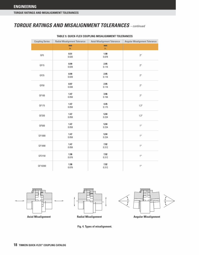
TABLE 9. QUICK-FLEX COUPLING MISALIGNMENT TOLERANCES
Coupling Series Radial Misalignment Tolerance Axial Misalignment Tolerance Angular Misalignment Tolerance
mmin.
mmin.
QF50.51 1.98
2°0.020 0.078
QF150.99 2.95
2°0.039 0.116
QF250.99 2.95
2°0.039 0.116
QF500.97 2.95
2°0.038 0.116
QF1001.47 3.96
2°0.058 0.156
QF1751.47 4.45
1.3°0.058 0.175
QF2501.47 5.94
1.3°0.058 0.234
QF5001.47 5.94
1°0.058 0.234
QF10001.47 5.94
1°0.058 0.234
QF18901.47 7.92
1°0.058 0.312
QF31501.98 7.92
1°0.078 0.312
QF102601.98 7.92
1°0.078 0.312
Axial Misalignment Radial Misalignment Angular Misalignment
Fig. 4. Types of misalignment.
TORQUE RATINGS AND MISALIGNMENT TOLERANCES – continued
ENGINEERING
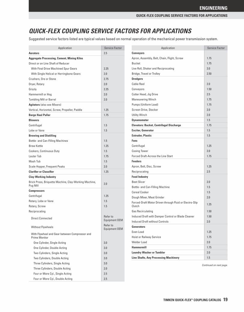
TIMKEN QUICK-FLEX® COUPLING CATALOG 19
QUICK-FLEX COUPLING SERVICE FACTORS FOR APPLICATIONS
Application Service Factor
Conveyors
Apron, Assembly, Belt, Chain, Flight, Screw 1.75
Bucket 1.75
Live Roll, Shaker and Reciprocating 3.0
Bridge, Travel or Trolley 2.50
Dredgers
Cable Reel 2.0
Conveyors 1.50
Cutter Head, Jig Drive 2.5
Maneuvering Winch 1.75
Pumps (Uniform Load) 1.75
Screen Drive, Stacker 2.0
Utility Winch 2.0
Dynamometer 1.5
Elevators: Bucket, Centrifugal Discharge 1.75
Exciter, Generator 1.5
Extruder, Plastic 1.5
Fans
Centrifugal 1.25
Cooing Tower 2.0
Forced Draft-Across the Line Start 1.75
Feeders
Apron, Belt, Disc, Screw 1.25
Reciprocating 2.5
Food Industry
Beet Slicer 2.0
Bottle- and Can-Filling Machine 1.5
Cereal Cooker 1.5
Dough Mixer, Meat Grinder 2.0
Forced-Draft Motor Driven through Fluid or Electro-Slip Clutch 1.25
Gas Recirculating 1.50
Induced Draft with Damper Control or Blade Cleaner 1.50
Induced Draft without Controls 2.0
Generators
Even Load 1.25
Hoist or Railway Service 1.75
Welder Load 2.0
Hammermill 1.75
Laundry Washer or Tumbler 2.0
Line Shafts, Any Processing Machinery 1.5
Application Service Factor
Aerators 2.5
Aggregate Processing, Cement, Mining Kilns
Direct or on Line Shaft of Reducer
With Final Drive Machined Spur Gears 2.25
With Single Helical or Herringbone Gears 2.0
Crushers, Ore or Stone 2.75
Dryer, Rotary 2.0
Grizzly 2.25
Hammermill or Hog 2.0
Tumbling Mill or Barrel 2.0
Agitators (also see Mixers)
Vertical, Horizontal, Screw, Propeller, Paddle 1.25
Barge Haul Puller 1.75
Blowers
Centrifugal 1.5
Lobe or Vane 1.5
Brewing and Distilling
Bottle- and Can-Filling Machines 1.5
Brew Kettle 1.25
Cookers, Continuous Duty 1.5
Lauter Tub 1.75
Mash Tub 1.5
Scale Hopper, Frequent Peaks 2.0
Clarifi er or Classifi er 1.25
Clay-Working Industry
Brick Press, Briquette Machine, Clay-Working Machine, Pug Mill 2.0
Compressors
Centrifugal 1.25
Rotary, Lobe or Vane 1.5
Rotary, Screw 1.5
Reciprocating
Direct Connected Refer to Equipment OEM
Without Flywheels Refer to Equipment OEM
With Flywheel and Gear between Compressor and Prime Monitor
One Cylinder, Single Acting 3.0
One Cylinder, Double Acting 3.0
Two Cylinders, Single Acting 3.0
Two Cylinders, Double Acting 3.0
Three Cylinders, Single Acting 3.0
Three Cylinders, Double Acting 2.0
Four or More Cyl., Single Acting 2.5
Four or More Cyl., Double Acting 2.5
Continued on next page.
QUICK-FLEX COUPLING SERVICE FACTORS FOR APPLICATIONSSuggested service factors listed are typical values based on normal operation of the mechanical power transmission system.
ENGINEERING
20 TIMKEN QUICK-FLEX® COUPLING CATALOG
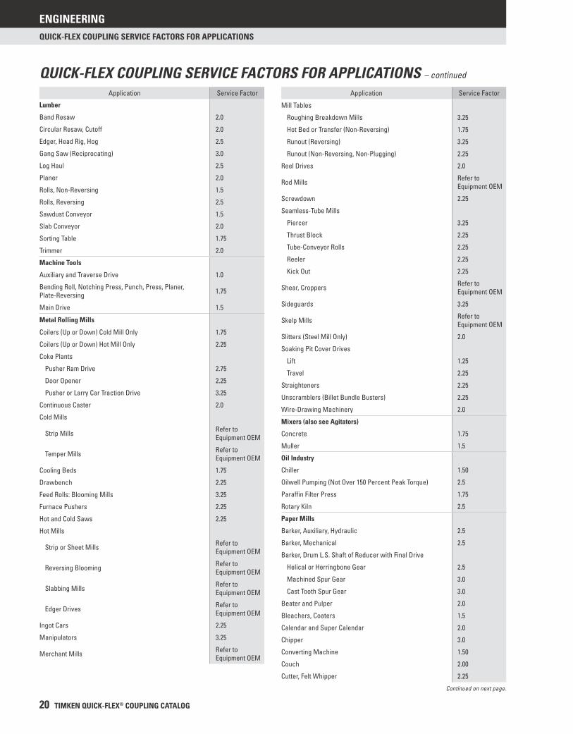
QUICK-FLEX COUPLING SERVICE FACTORS FOR APPLICATIONS
Application Service Factor
Mill Tables
Roughing Breakdown Mills 3.25
Hot Bed or Transfer (Non-Reversing) 1.75
Runout (Reversing) 3.25
Runout (Non-Reversing, Non-Plugging) 2.25
Reel Drives 2.0
Rod Mills Refer to Equipment OEM
Screwdown 2.25
Seamless-Tube Mills
Piercer 3.25
Thrust Block 2.25
Tube-Conveyor Rolls 2.25
Reeler 2.25
Kick Out 2.25
Shear, Croppers Refer to Equipment OEM
Sideguards 3.25
Skelp Mills Refer to Equipment OEM
Slitters (Steel Mill Only) 2.0
Soaking Pit Cover Drives
Lift 1.25
Travel 2.25
Straighteners 2.25
Unscramblers (Billet Bundle Busters) 2.25
Wire-Drawing Machinery 2.0
Mixers (also see Agitators)
Concrete 1.75
Muller 1.5
Oil Industry
Chiller 1.50
Oilwell Pumping (Not Over 150 Percent Peak Torque) 2.5
Paraffi n Filter Press 1.75
Rotary Kiln 2.5
Paper Mills
Barker, Auxiliary, Hydraulic 2.5
Barker, Mechanical 2.5
Barker, Drum L.S. Shaft of Reducer with Final Drive
Helical or Herringbone Gear 2.5
Machined Spur Gear 3.0
Cast Tooth Spur Gear 3.0
Beater and Pulper 2.0
Bleachers, Coaters 1.5
Calendar and Super Calendar 2.0
Chipper 3.0
Converting Machine 1.50
Couch 2.00
Cutter, Felt Whipper 2.25
Application Service Factor
Lumber
Band Resaw 2.0
Circular Resaw, Cutoff 2.0
Edger, Head Rig, Hog 2.5
Gang Saw (Reciprocating) 3.0
Log Haul 2.5
Planer 2.0
Rolls, Non-Reversing 1.5
Rolls, Reversing 2.5
Sawdust Conveyor 1.5
Slab Conveyor 2.0
Sorting Table 1.75
Trimmer 2.0
Machine Tools
Auxiliary and Traverse Drive 1.0
Bending Roll, Notching Press, Punch, Press, Planer, Plate-Reversing 1.75
Main Drive 1.5
Metal Rolling Mills
Coilers (Up or Down) Cold Mill Only 1.75
Coilers (Up or Down) Hot Mill Only 2.25
Coke Plants
Pusher Ram Drive 2.75
Door Opener 2.25
Pusher or Larry Car Traction Drive 3.25
Continuous Caster 2.0
Cold Mills
Strip Mills Refer to Equipment OEM
Temper Mills Refer to Equipment OEM
Cooling Beds 1.75
Drawbench 2.25
Feed Rolls: Blooming Mills 3.25
Furnace Pushers 2.25
Hot and Cold Saws 2.25
Hot Mills
Strip or Sheet Mills Refer to Equipment OEM
Reversing Blooming Refer to Equipment OEM
Slabbing Mills Refer to Equipment OEM
Edger Drives Refer to Equipment OEM
Ingot Cars 2.25
Manipulators 3.25
Merchant Mills Refer to Equipment OEM
QUICK-FLEX COUPLING SERVICE FACTORS FOR APPLICATIONS – continued
Continued on next page.
ENGINEERING
TIMKEN QUICK-FLEX® COUPLING CATALOG 21
QUICK-FLEX COUPLING SERVICE FACTORS FOR APPLICATIONS
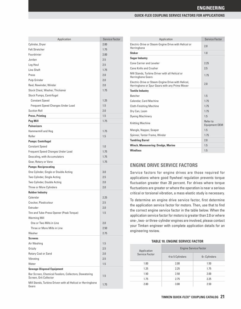
ENGINE DRIVE SERVICE FACTORSService factors for engine drives are those required for applications where good fl ywheel regulation prevents torque fl uctuation greater than 20 percent. For drives where torque fl uctuations are greater or where the operation is near a serious critical or torsional vibration, a mass elastic study is necessary.
To determine an engine drive service factor, fi rst determine the application service factor for motors. Then, use that to fi nd the correct engine service factor in the table below. When the application service factor for motors is greater than 2.0 or where one-, two- or three-cylinder engines are involved, please contact your Timken engineer with complete application details for an engineering review.
TABLE 10. ENGINE SERVICE FACTOR
ApplicationService Factor
Engine Service Factor
4 to 5 Cylinders 6+ Cylinders
1.00 2.00 1.50
1.25 2.25 1.75
1.50 2.50 2.00
1.75 2.75 2.25
2.00 3.00 2.50
Application Service Factor
Cylinder, Dryer 2.00
Felt Stretcher 1.75
Fourdrinier 2.00
Jordan 2.5
Log Haul 2.5
Line Shaft 1.75
Press 2.0
Pulp Grinder 2.0
Reel, Rewinder, Winder 2.0
Stock Chest, Washer, Thickener 1.75
Stock Pumps, Centrifugal
Constant Speed 1.25
Frequent Speed Changes Under Load 1.5
Suction Roll 2.0
Press, Printing 1.5
Pug Mill 1.75
Pulverizers
Hammermill and Hog 1.75
Roller 1.5
Pumps: Centrifugal
Constant Speed 1.0
Frequent Speed Changes Under Load 1.75
Descaling, with Accumulators 1.75
Gear, Rotary or Vane 1.75
Pumps: Reciprocating
One Cylinder, Single or Double Acting 3.0
Two Cylinder, Single Acting 2.5
Two Cylinder, Double Acting 2.0
Three or More Cylinders 2.0
Rubber Industry
Calendar 2.25
Cracker, Plasticolour 2.5
Extruder 2.0
Tire and Tube-Press Opener (Peak Torque) 1.5
Warming Mill
One or Two Mills in Line 2.0
Three or More Mills in Line 2.50
Washer 2.75
Screens
Air Washing 1.5
Grizzly 2.5
Rotary Coal or Sand 2.0
Vibrating 2.5
Water 1.5
Sewage-Disposal Equipment
Bar Screen, Chemical Feeders, Collectors, Dewatering Screen, Grit Collector 1.5
Mill Stands, Turbine Driven with all Helical or Herringbone Gears 1.75
Application Service Factor
Electric-Drive or Steam-Engine Drive with Helical or Herringbone 2.0
Stoker 1.0
Sugar Industry
Cone Carrier and Leveler 2.25
Cane Knife and Crusher 2.5
Mill Stands, Turbine Driver with all Helical or Herringbone Gears 1.75
Electric-Drive or Steam-Engine Drive with Helical, Herringbone or Spur Gears with any Prime Mover 2.0
Textile Industry
Batcher 1.5
Calendar, Card Machine 1.75
Cloth-Finishing Machine 1.75
Dry Can, Loom 1.75
Dyeing Machinery 1.5
Knitting Machine Refer to Equipment OEM
Mangle, Napper, Soaper 1.5
Spinner, Tenter Frame, Winder 1.75
Tumbling Barrel 2.0
Winch, Maneuvering: Dredge, Marine 1.5
Windlass 1.5
ENGINEERING
22 TIMKEN QUICK-FLEX® COUPLING CATALOG
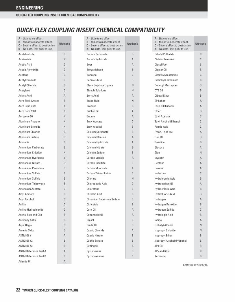
QUICK-FLEX COUPLING INSERT CHEMICAL COMPATIBILITY
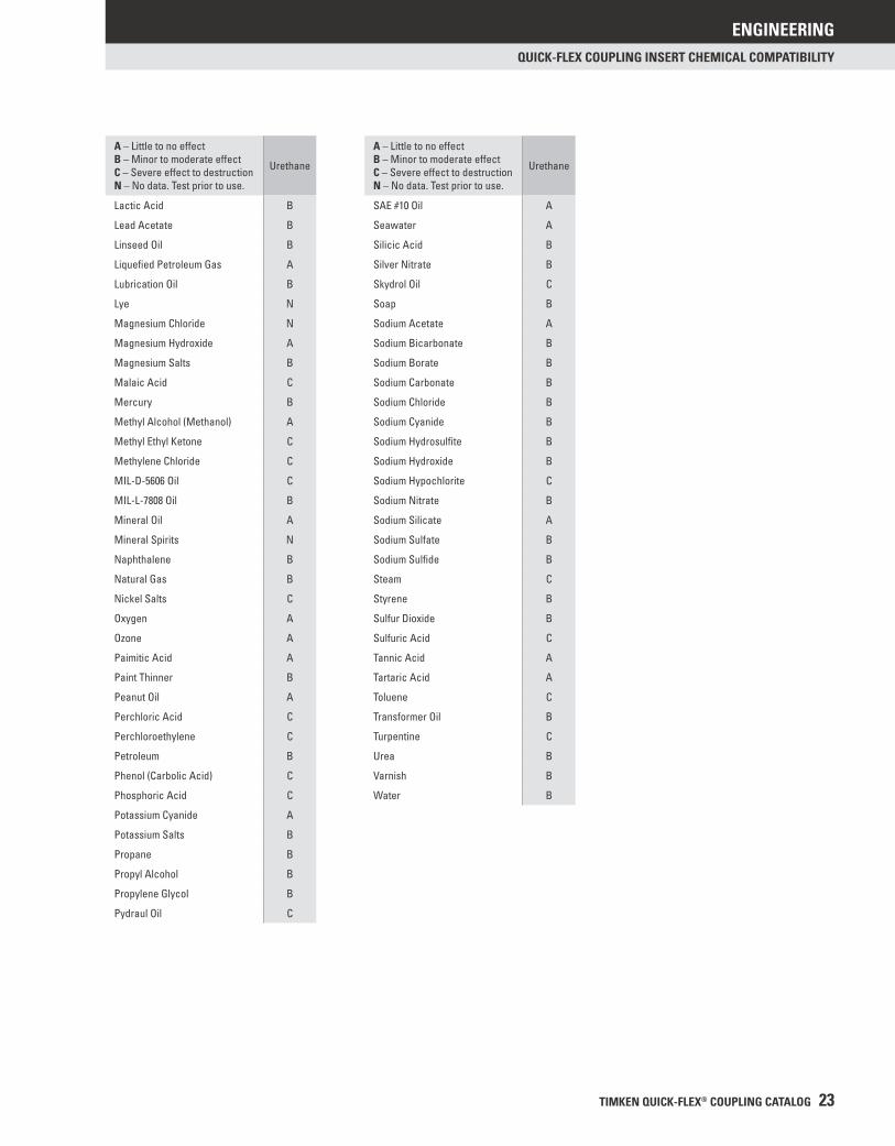
QUICK-FLEX COUPLING INSERT CHEMICAL COMPATIBILITYA – Little to no effectB – Minor to moderate effectC – Severe effect to destructionN – No data. Test prior to use.
Urethane
Acetaldehyde C
Acetamide N
Acetic Acid C
Acetic Anhydride C
Acetone C
Acetyl Bromide C
Acetyl Chloride C
Acetylene C
Adipic Acid A
Aero Shell Grease B
Aero Lubriplate A
Aero Safe 2300 N
Aerozene 50 N
Aluminum Acetate N
Aluminum Bromide N
Aluminum Chloride B
Aluminum Sulfate B
Ammonia B
Ammonium Carbonate B
Ammonium Chloride N
Ammonium Hydroxide B
Ammonium Nitrate B
Ammonium Persulfate B
Ammonium Sulfate B
Ammonium Sulfi de B
Ammonium Thiocynate B
Amonnium Acetate C
Amyl Acetate C
Amyl Alcohol C
Aniline C
Aniline Hydrochloride C
Animal Fats and Oils B
Antimony Salts B
Aqua Regia C
Arsenic Salts B
ASTM Oil #1 A
ASTM Oil #2 B
ASTM Oil #3 B
ASTM Reference Fuel A A
ASTM Reference Fuel B B
Atlantic Oil A
A – Little to no effectB – Minor to moderate effectC – Severe effect to destructionN – No data. Test prior to use.
Urethane
Barium Carbonate B
Barium Hydroxide A
Beer A
Benzaldehyde B
Benzene C
Benzoic Acid B
Black Sulphate Liquors N
Bleach Solutions N
Boric Acid A
Brake Fluid N
Bromine B
Bunker Oil A
Butane A
Butyl Acetate C
Butyl Alcohol B
Calcium Carbonate B
Calcium Chloride A
Calcium Hydroxide A
Calcium Nitrate B
Calcium Sulfate B
Carbon Dioxide A
Carbon Disulfi de B
Carbon Monoxide A
Carbon Tetrachloride C
Chlorine N
Chloroacetic Acid C
Chloroform C
Chromic Acid C
Chromium Potassium Sulfate B
Citric Acid B
Corn Oil A
Cottonseed Oil A
Cresol C
Crude Oil B
Cupric Chloride A
Cupric Nitrate B
Cupric Sulfate B
Cutting Oil B
Cyclohexane B
Cyclohexanone C
A – Little to no effectB – Minor to moderate effectC – Severe effect to destructionN – No data. Test prior to use.
Urethane
Dibutyl Phthalate C
Dichlorobenzene C
Diesel Fuel B
Diester Oil B
Dimethyl Acetamide C
Dimethyl Formamide C
Dodecyl Mercaptan B
DTE Oil B
Dibutyl Ether B
EP Lubes A
Esso #90 Lube Oil A
Ether B
Ethyl Acetate C
Ethyl Alcohol (Ethanol) C
Formic Acid C
Freon, 12 or 113 A
Fuel Oil B
Gasoline B
Glucose A
Glue N
Glycerin A
Heptane A
Hexane A
Hydrazine C
Hydrobromic Acid B
Hydrocarbon Oil A
Hydrochloric Acid B
Hydrofl uoric Acid B
Hydrogen A
Hydrogen Peroxide B
Hydrogen Sulfi de C
Hydrologic Acid B
Iodine A
Isobutyl Alcohol N
Isopropyl Chloride N
Isopropyl Ether B
Isopropyl Alcohol (Propanol) B
JP4 Oil B
JP5 and 6 Oil C
Kerosene B
Continued on next page.
ENGINEERING
TIMKEN QUICK-FLEX® COUPLING CATALOG 23
QUICK-FLEX COUPLING INSERT CHEMICAL COMPATIBILITY
A – Little to no effectB – Minor to moderate effectC – Severe effect to destructionN – No data. Test prior to use.
Urethane
Lactic Acid B
Lead Acetate B
Linseed Oil B
Liquefi ed Petroleum Gas A
Lubrication Oil B
Lye N
Magnesium Chloride N
Magnesium Hydroxide A
Magnesium Salts B
Malaic Acid C
Mercury B
Methyl Alcohol (Methanol) A
Methyl Ethyl Ketone C
Methylene Chloride C
MIL-D-5606 Oil C
MIL-L-7808 Oil B
Mineral Oil A
Mineral Spirits N
Naphthalene B
Natural Gas B
Nickel Salts C
Oxygen A
Ozone A
Paimitic Acid A
Paint Thinner B
Peanut Oil A
Perchloric Acid C
Perchloroethylene C
Petroleum B
Phenol (Carbolic Acid) C
Phosphoric Acid C
Potassium Cyanide A
Potassium Salts B
Propane B
Propyl Alcohol B
Propylene Glycol B
Pydraul Oil C
A – Little to no effectB – Minor to moderate effectC – Severe effect to destructionN – No data. Test prior to use.
Urethane
SAE #10 Oil A
Seawater A
Silicic Acid B
Silver Nitrate B
Skydrol Oil C
Soap B
Sodium Acetate A
Sodium Bicarbonate B
Sodium Borate B
Sodium Carbonate B
Sodium Chloride B
Sodium Cyanide B
Sodium Hydrosulfi te B
Sodium Hydroxide B
Sodium Hypochlorite C
Sodium Nitrate B
Sodium Silicate A
Sodium Sulfate B
Sodium Sulfi de B
Steam C
Styrene B
Sulfur Dioxide B
Sulfuric Acid C
Tannic Acid A
Tartaric Acid A
Toluene C
Transformer Oil B
Turpentine C
Urea B
Varnish B
Water B
ENGINEERING
24 TIMKEN QUICK-FLEX® COUPLING CATALOG
INSTALLATION GUIDES • STANDARD COUPLING
Please complete the following steps to install Timken Quick-Flex couplings.
You should have the following pieces before starting the job:• Two hubs• One insert• One cover with included hardware
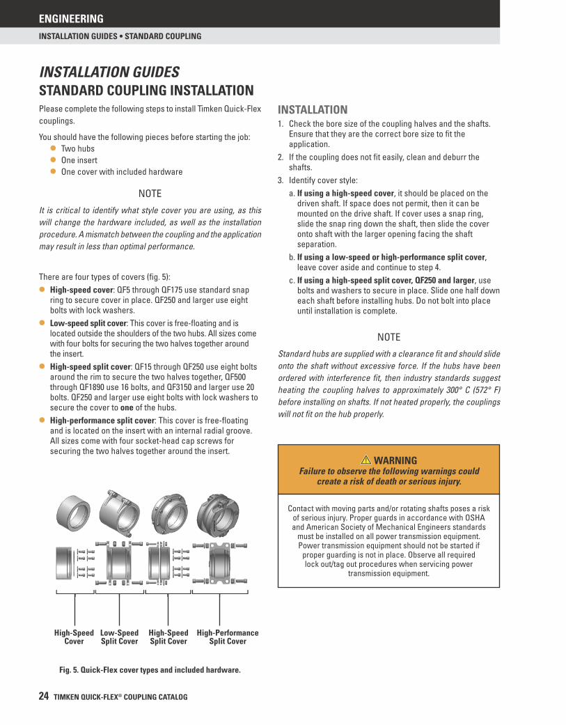
There are four types of covers (fi g. 5):
• High-speed cover: QF5 through QF175 use standard snap ring to secure cover in place. QF250 and larger use eight bolts with lock washers.
• Low-speed split cover: This cover is free-fl oating and is located outside the shoulders of the two hubs. All sizes come with four bolts for securing the two halves together around the insert.
• High-speed split cover: QF15 through QF250 use eight bolts around the rim to secure the two halves together, QF500 through QF1890 use 16 bolts, and QF3150 and larger use 20 bolts. QF250 and larger use eight bolts with lock washers to secure the cover to one of the hubs.
• High-performance split cover: This cover is free-fl oating and is located on the insert with an internal radial groove. All sizes come with four socket-head cap screws for securing the two halves together around the insert.
INSTALLATION GUIDESSTANDARD COUPLING INSTALLATION
Fig. 5. Quick-Flex cover types and included hardware.
INSTALLATION1. Check the bore size of the coupling halves and the shafts.
Ensure that they are the correct bore size to fi t the application.
2. If the coupling does not fi t easily, clean and deburr the shafts.
3. Identify cover style:a. If using a high-speed cover, it should be placed on the
driven shaft. If space does not permit, then it can be mounted on the drive shaft. If cover uses a snap ring, slide the snap ring down the shaft, then slide the cover onto shaft with the larger opening facing the shaft separation.
b. If using a low-speed or high-performance split cover, leave cover aside and continue to step 4.
c. If using a high-speed split cover, QF250 and larger, use bolts and washers to secure in place. Slide one half down each shaft before installing hubs. Do not bolt into place until installation is complete.
High-Speed Cover
Low-Speed Split Cover
High-Speed Split Cover
High-Performance Split Cover
NOTE
It is critical to identify what style cover you are using, as this will change the hardware included, as well as the installation procedure. A mismatch between the coupling and the application may result in less than optimal performance.
NOTE
Standard hubs are supplied with a clearance fi t and should slide onto the shaft without excessive force. If the hubs have been ordered with interference fi t, then industry standards suggest heating the coupling halves to approximately 300° C (572° F) before installing on shafts. If not heated properly, the couplings will not fi t on the hub properly.
WARNINGFailure to observe the following warnings could
create a risk of death or serious injury.
Contact with moving parts and/or rotating shafts poses a risk of serious injury. Proper guards in accordance with OSHA and American Society of Mechanical Engineers standards
must be installed on all power transmission equipment. Power transmission equipment should not be started if
proper guarding is not in place. Observe all required lock out/tag out procedures when servicing power
transmission equipment.
ENGINEERING
TIMKEN QUICK-FLEX® COUPLING CATALOG 25
INSTALLATION GUIDES • STANDARD COUPLING
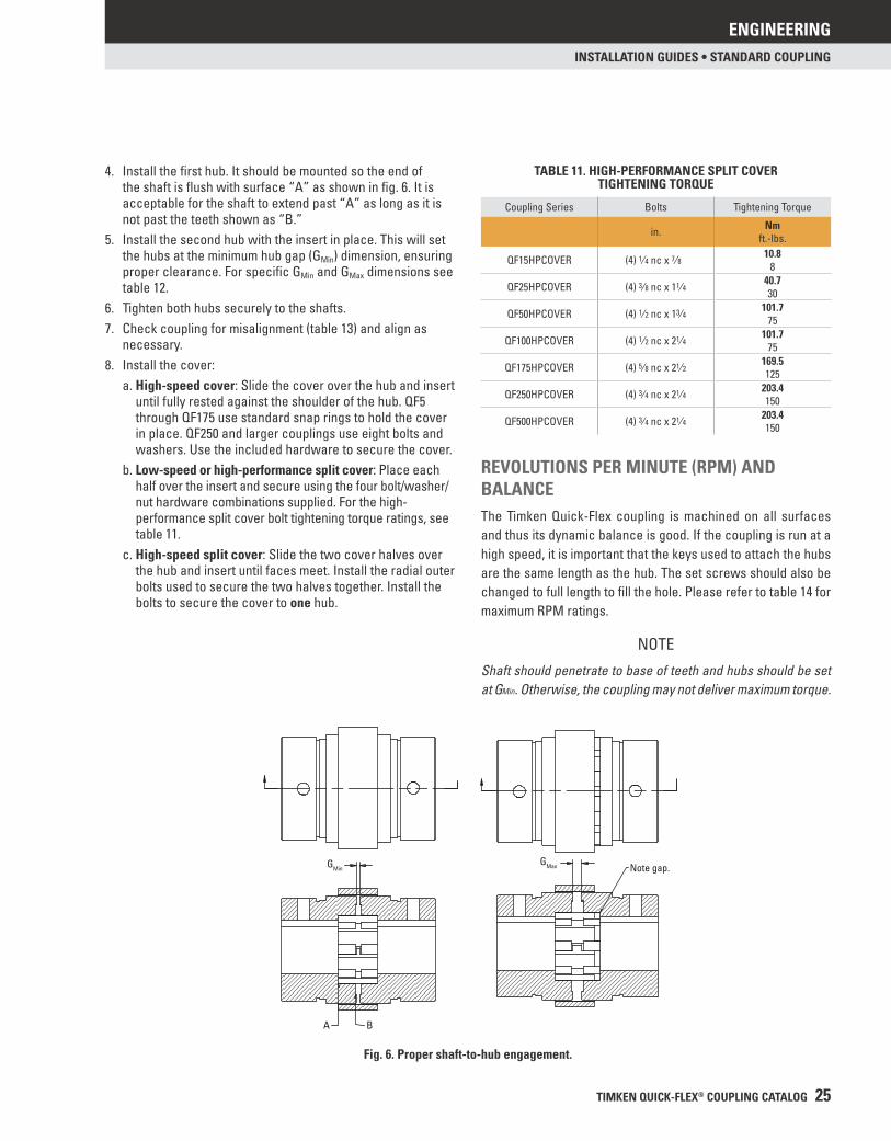
4. Install the fi rst hub. It should be mounted so the end of the shaft is fl ush with surface “A” as shown in fi g. 6. It is acceptable for the shaft to extend past “A” as long as it is not past the teeth shown as “B.”
5. Install the second hub with the insert in place. This will set the hubs at the minimum hub gap (GMin) dimension, ensuring proper clearance. For specifi c GMin and GMax dimensions see table 12.
6. Tighten both hubs securely to the shafts.7. Check coupling for misalignment (table 13) and align as
necessary.8. Install the cover:
a. High-speed cover: Slide the cover over the hub and insert until fully rested against the shoulder of the hub. QF5 through QF175 use standard snap rings to hold the cover in place. QF250 and larger couplings use eight bolts and washers. Use the included hardware to secure the cover.
b. Low-speed or high-performance split cover: Place each half over the insert and secure using the four bolt/washer/nut hardware combinations supplied. For the high-performance split cover bolt tightening torque ratings, see table 11.
c. High-speed split cover: Slide the two cover halves over the hub and insert until faces meet. Install the radial outer bolts used to secure the two halves together. Install the bolts to secure the cover to one hub.
Fig. 6. Proper shaft-to-hub engagement.
BA
Note gap. GMax GMin
REVOLUTIONS PER MINUTE (RPM) AND BALANCEThe Timken Quick-Flex coupling is machined on all surfaces and thus its dynamic balance is good. If the coupling is run at a high speed, it is important that the keys used to attach the hubs are the same length as the hub. The set screws should also be changed to full length to fi ll the hole. Please refer to table 14 for maximum RPM ratings.
TABLE 11. HIGH-PERFORMANCE SPLIT COVERTIGHTENING TORQUE
Coupling Series Bolts Tightening Torque
in. Nmft.-lbs.
QF15HPCOVER (4) 1⁄4 nc x 7⁄8 10.88
QF25HPCOVER (4) 3⁄8 nc x 11⁄4 40.730
QF50HPCOVER (4) 1⁄2 nc x 13⁄4 101.775
QF100HPCOVER (4) 1⁄2 nc x 21⁄4 101.775
QF175HPCOVER (4) 5⁄8 nc x 21⁄2 169.5125
QF250HPCOVER (4) 3⁄4 nc x 21⁄4 203.4150
QF500HPCOVER (4) 3⁄4 nc x 21⁄4 203.4150
NOTE
Shaft should penetrate to base of teeth and hubs should be set at GMin. Otherwise, the coupling may not deliver maximum torque.
ENGINEERING
26 TIMKEN QUICK-FLEX® COUPLING CATALOG
INSTALLATION GUIDES • STANDARD COUPLING
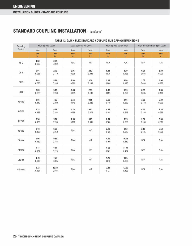
TABLE 12. QUICK-FLEX STANDARD COUPLING HUB GAP (G) DIMENSIONS
CouplingSeries
High-Speed Cover Low-Speed Split Cover High-Speed Split Cover High-Performance Split Cover
GMin GMax GMin GMax GMin GMax GMin GMax
mmin.
mmin.
mmin.
mmin.
mmin.
mmin.
mmin.
mmin.
1.60 2.34N/A N/A N/A N/A N/A N/AQF5 0.063 0.092
0.91 2.79 0.91 2.52 0.91 3.20 0.91 5.59QF15 0.036 0.110 0.036 0.099 0.036 0.126 0.036 0.220
2.03 5.21 2.03 3.39 2.03 3.56 2.03 4.06QF25 0.080 0.205 0.080 0.133 0.080 0.140 0.080 0.160
0.89 5.28 0.89 2.57 0.89 5.59 0.89 4.06QF50 0.035 0.208 0.035 0.101 0.035 0.220 0.035 0.160
3.56 7.37 3.56 9.65 3.56 9.65 3.56 9.40QF100 0.140 0.290 0.140 0.380 0.140 0.380 0.140 0.370
4.78 5.28 4.78 9.53 4.78 8.84 4.57 9.35QF175 0.188 0.208 0.188 0.375 0.188 0.348 0.180 0.368
2.54 5.84 2.54 9.27 2.54 6.35 2.54 8.08QF250 0.100 0.230 0.100 0.365 0.100 0.250 0.100 0.318
3.18 6.35N/A N/A
3.18 9.53 3.18 9.53QF500 0.125 0.250 0.125 0.375 0.125 0.375
4.06 9.86N/A N/A
4.06 10.41N/A N/AQF1000 0.160 0.388 0.160 0.410
5.12 7.06N/A N/A
5.13 11.53N/A N/AQF1890 0.202 0.278 0.202 0.454
1.78 7.75N/A N/A
1.78 9.65N/A N/AQF3150 0.070 0.305 0.070 0.380
3.23 12.83N/A N/A
3.23 12.50N/A N/AQF10260 0.127 0.505 0.127 0.492
STANDARD COUPLING INSTALLATION – continued

ENGINEERING
TIMKEN QUICK-FLEX® COUPLING CATALOG 27
INSTALLATION GUIDES • STANDARD COUPLING
TABLE 13. QUICK-FLEX STANDARD COUPLING MISALIGNMENT TOLERANCES
Coupling Series Radial Misalignment Tolerance Axial Misalignment Tolerance Angular Misalignment Tolerancemmin.
mmin.
QF5 0.51 1.98 2°0.020 0.078
QF15 0.99 2.95 2°0.039 0.116
QF25 0.99 2.95 2°0.039 0.116
QF50 0.97 2.95 2°0.038 0.116
QF100 1.47 3.96 2°0.058 0.156
QF175 1.47 4.45 1.3°0.058 0.175
QF250 1.47 5.94 1.3°0.058 0.234
QF500 1.47 5.94 1°0.058 0.234
QF1000 1.47 5.94 1°0.058 0.234
QF1890 1.47 7.92 1°0.058 0.312
QF3150 1.98 7.92 1°0.078 0.312
QF10260 1.98 7.92 1°0.078 0.312
TABLE 14. QUICK-FLEX STANDARD COUPLING MAXIMUM RPM RATINGS(1)
Coupling Series High-Speed Cover Low-Speed Split Cover High-Speed Split Cover High-Performance Split Cover
RPM RPM RPM RPM
QF5 12000 N/A N/A N/A
QF15 9000 400 9000 9000
QF25 7000 375 7000 7000
QF50 6000 350 6000 6000
QF100 4800 300 4800 4800
QF175 4200 250 4200 4200
QF250 3800 200 3800 3800
QF500 3400 N/A 3400 3400
QF1000 3000 N/A 3000 N/A
QF1890 2400 N/A 2400 N/A
QF3150 2000 N/A 2000 N/A
QF10260 1200 N/A 1200 N/A
(1)Maximum RPM ratings are for off-the-shelf Quick-Flex couplings. If your application requires higher RPM ratings, the couplings should be dynamically balanced.
ENGINEERING
28 TIMKEN QUICK-FLEX® COUPLING CATALOG
INSTALLATION GUIDES • SINGLE-ENDED SPACER COUPLING
Please complete the following steps to install Timken Quick-Flex single-ended spacer couplings.
You should have the following pieces before starting the job:• One coupling hub• One fl anged hub• One spacer body• One insert• One cover with included hardware
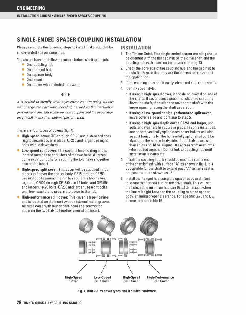
There are four types of covers (fi g. 7):
• High-speed cover: QF5 through QF175 use a standard snap ring to secure cover in place. QF250 and larger use eight bolts with lock washers.
• Low-speed split cover: This cover is free-fl oating and is located outside the shoulders of the two hubs. All sizes come with four bolts for securing the two halves together around the insert.
• High-speed split cover: This cover will be supplied in four pieces to fi t over the spacer body. QF15 through QF250 use eight bolts around the rim to secure the two halves together, QF500 through QF1890 use 16 bolts, and QF3150 and larger use 20 bolts. QF250 and larger use eight bolts with lock washers to secure the cover to the hub.
• High-performance split cover: This cover is free-fl oating and is located on the insert with an internal radial groove. All sizes come with four socket-head cap screws for securing the two halves together around the insert.
SINGLE-ENDED SPACER COUPLING INSTALLATIONINSTALLATION1. The Timken Quick-Flex single-ended spacer coupling should
be oriented with the fl anged hub on the drive shaft and the coupling hub with insert on the driven shaft (fi g. 8).
2. Check the bore size of the coupling hub and fl anged hub to the shafts. Ensure that they are the correct bore size to fi t the application.
3. If the coupling does not fi t easily, clean and deburr the shafts.4. Identify cover style:
a. If using a high-speed cover, it should be placed on one of the shafts. If cover uses a snap ring, slide the snap ring down the shaft, then slide the cover onto shaft with the larger opening facing the shaft separation.
b. If using a low-speed or high-performance split cover, leave cover aside and continue to step 5.
c. If using a high-speed split cover, QF250 and larger, use bolts and washers to secure in place. In some instances, one or both vertically split pieces cover halves will also be split horizontally. The horizontally split half should be placed on the spacer body side. If both halves are split then splits should be aligned 90 degrees from each other when bolted together. Do not bolt to coupling hub until installation is complete.
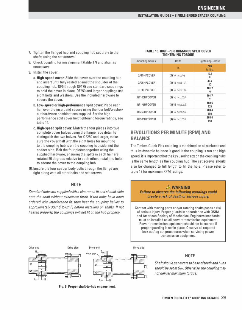
5. Install the coupling hub. It should be mounted so the end of the shaft is fl ush with surface “A” as shown in fi g. 8. It is acceptable for the shaft to extend past “A” as long as it is not past the teeth shown as “B.”
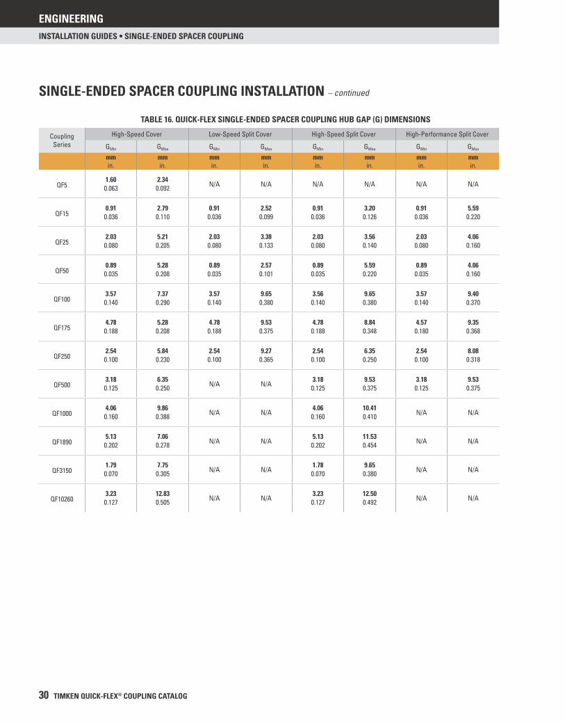
6. Install the fl anged hub using the spacer body and insert to locate the fl anged hub on the drive shaft. This will set the hubs at the minimum hub gap (GMin) dimension when the insert is tight between the coupling hub and spacer body, ensuring proper clearance. For specifi c GMin and GMax dimensions see table 16.
Fig. 7. Quick-Flex cover types and included hardware.
High-Speed Cover
Low-Speed Split Cover
High-Speed Split Cover
High-Performance Split Cover
NOTE
It is critical to identify what style cover you are using, as this will change the hardware included, as well as the installation procedure. A mismatch between the coupling and the application may result in less than optimal performance.
ENGINEERING
TIMKEN QUICK-FLEX® COUPLING CATALOG 29
INSTALLATION GUIDES • SINGLE-ENDED SPACER COUPLING
7. Tighten the fl anged hub and coupling hub securely to the shafts using the set screws.
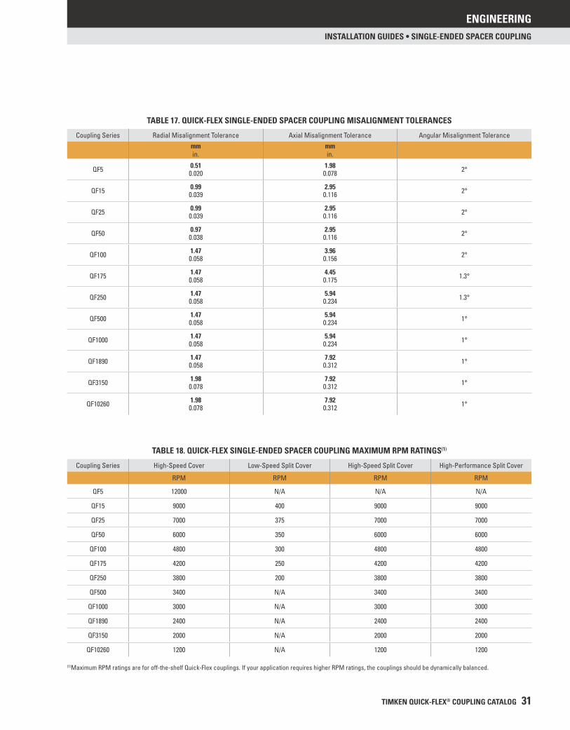
8. Check coupling for misalignment (table 17) and align as necessary.
9. Install the cover:a. High-speed cover: Slide the cover over the coupling hub
and insert until fully rested against the shoulder of the coupling hub. QF5 through QF175 use standard snap rings to hold the cover in place. QF250 and larger couplings use eight bolts and washers. Use the included hardware to secure the cover.
b. Low-speed or high-performance split cover: Place each half over the insert and secure using the four bolt/washer/nut hardware combinations supplied. For the high-performance split cover bolt tightening torque ratings, see table 15.
c. High-speed split cover: Match the four pieces into two complete cover halves using the fl ange face detail to distinguish the two halves. For QF250 and larger, make sure the cover half with the eight holes for mounting to the coupling hub is on the coupling hub side, not the spacer side. Bolt the four pieces together using the supplied hardware, ensuring the splits in each half are rotated 90 degrees relative to each other. Install the bolts to secure the cover to the coupling hub.
10. Ensure the four spacer body bolts through the fl ange are tight along with all other bolts and set screws.
REVOLUTIONS PER MINUTE (RPM) AND BALANCEThe Timken Quick-Flex coupling is machined on all surfaces and thus its dynamic balance is good. If the coupling is run at a high speed, it is important that the key used to attach the coupling hubs is the same length as the coupling hub. The set screws should also be changed to full length to fi ll the hole. Please refer to table 18 for maximum RPM ratings.
NOTE
Standard hubs are supplied with a clearance fi t and should slide onto the shaft without excessive force. If the hubs have been ordered with interference fi t, then heat the coupling halves to approximately 300° C (572° F) before installing on shafts. If not heated properly, the couplings will not fi t on the hub properly.
Fig. 8. Proper shaft-to-hub engagement.
NOTE
Shaft should penetrate to base of teeth and hubs should be set at GMin. Otherwise, the coupling may not deliver maximum torque.
Note gap. GMax GMin
Drive endDrive end Drive side Drive side
A B A B
TABLE 15. HIGH-PERFORMANCE SPLIT COVERTIGHTENING TORQUE
Coupling Series Bolts Tightening Torque
in. Nmft.-lbs.
QF15HPCOVER (4) 1⁄4 nc x 7⁄8 10.88
QF25HPCOVER (4) 3⁄8 nc x 11⁄4 40.730
QF50HPCOVER (4) 1⁄2 nc x 13⁄4 101.775
QF100HPCOVER (4) 1⁄2 nc x 21⁄4 101.775
QF175HPCOVER (4) 5⁄8 nc x 21⁄2 169.5125
QF250HPCOVER (4) 3⁄4 nc x 21⁄4 203.4150
QF500HPCOVER (4) 3⁄4 nc x 21⁄4 203.4150
WARNINGFailure to observe the following warnings could
create a risk of death or serious injury.
Contact with moving parts and/or rotating shafts poses a risk of serious injury. Proper guards in accordance with OSHA and American Society of Mechanical Engineers standards
must be installed on all power transmission equipment. Power transmission equipment should not be started if
proper guarding is not in place. Observe all required lock out/tag out procedures when servicing power
transmission equipment.
ENGINEERING
30 TIMKEN QUICK-FLEX® COUPLING CATALOG
INSTALLATION GUIDES • SINGLE-ENDED SPACER COUPLING
TABLE 16. QUICK-FLEX SINGLE-ENDED SPACER COUPLING HUB GAP (G) DIMENSIONS
CouplingSeries
High-Speed Cover Low-Speed Split Cover High-Speed Split Cover High-Performance Split Cover
GMin GMax GMin GMax GMin GMax GMin GMax
mmin.
mmin.
mmin.
mmin.
mmin.
mmin.
mmin.
mmin.
1.60 2.34N/A N/A N/A N/A N/A N/AQF5 0.063 0.092
0.91 2.79 0.91 2.52 0.91 3.20 0.91 5.59QF15 0.036 0.110 0.036 0.099 0.036 0.126 0.036 0.220
2.03 5.21 2.03 3.38 2.03 3.56 2.03 4.06QF25 0.080 0.205 0.080 0.133 0.080 0.140 0.080 0.160
0.89 5.28 0.89 2.57 0.89 5.59 0.89 4.06QF50 0.035 0.208 0.035 0.101 0.035 0.220 0.035 0.160
3.57 7.37 3.57 9.65 3.56 9.65 3.57 9.40QF100 0.140 0.290 0.140 0.380 0.140 0.380 0.140 0.370
4.78 5.28 4.78 9.53 4.78 8.84 4.57 9.35QF175 0.188 0.208 0.188 0.375 0.188 0.348 0.180 0.368
2.54 5.84 2.54 9.27 2.54 6.35 2.54 8.08QF250 0.100 0.230 0.100 0.365 0.100 0.250 0.100 0.318
3.18 6.35N/A N/A
3.18 9.53 3.18 9.53QF500 0.125 0.250 0.125 0.375 0.125 0.375
4.06 9.86N/A N/A
4.06 10.41N/A N/AQF1000 0.160 0.388 0.160 0.410
5.13 7.06N/A N/A
5.13 11.53N/A N/AQF1890 0.202 0.278 0.202 0.454
1.79 7.75N/A N/A
1.78 9.65N/A N/AQF3150 0.070 0.305 0.070 0.380
3.23 12.83N/A N/A
3.23 12.50N/A N/AQF10260 0.127 0.505 0.127 0.492
SINGLE-ENDED SPACER COUPLING INSTALLATION – continued
ENGINEERING
TIMKEN QUICK-FLEX® COUPLING CATALOG 31
INSTALLATION GUIDES • SINGLE-ENDED SPACER COUPLING
TABLE 17. QUICK-FLEX SINGLE-ENDED SPACER COUPLING MISALIGNMENT TOLERANCES
Coupling Series Radial Misalignment Tolerance Axial Misalignment Tolerance Angular Misalignment Tolerancemmin.
mmin.
QF5 0.51 1.98 2°0.020 0.078
QF15 0.99 2.95 2°0.039 0.116
QF25 0.99 2.95 2°0.039 0.116
QF50 0.97 2.95 2°0.038 0.116
QF100 1.47 3.96 2°0.058 0.156
QF175 1.47 4.45 1.3°0.058 0.175
QF250 1.47 5.94 1.3°0.058 0.234
QF500 1.47 5.94 1°0.058 0.234
QF1000 1.47 5.94 1°0.058 0.234
QF1890 1.47 7.92 1°0.058 0.312
QF3150 1.98 7.92 1°0.078 0.312
QF10260 1.98 7.92 1°0.078 0.312
TABLE 18. QUICK-FLEX SINGLE-ENDED SPACER COUPLING MAXIMUM RPM RATINGS(1)
Coupling Series High-Speed Cover Low-Speed Split Cover High-Speed Split Cover High-Performance Split Cover
RPM RPM RPM RPM
QF5 12000 N/A N/A N/A
QF15 9000 400 9000 9000
QF25 7000 375 7000 7000
QF50 6000 350 6000 6000
QF100 4800 300 4800 4800
QF175 4200 250 4200 4200
QF250 3800 200 3800 3800
QF500 3400 N/A 3400 3400
QF1000 3000 N/A 3000 3000
QF1890 2400 N/A 2400 2400
QF3150 2000 N/A 2000 2000
QF10260 1200 N/A 1200 1200
(1)Maximum RPM ratings are for off-the-shelf Quick-Flex couplings. If your application requires higher RPM ratings, the couplings should be dynamically balanced.
ENGINEERING
32 TIMKEN QUICK-FLEX® COUPLING CATALOG
INSTALLATION GUIDES • DOUBLE-ENDED SPACER COUPLING
Please complete the following steps to install Timken Quick-Flex double-ended spacer couplings.
You should have the following pieces before starting the job:• Two hubs• One spacer body• Two inserts• Two covers with included hardware
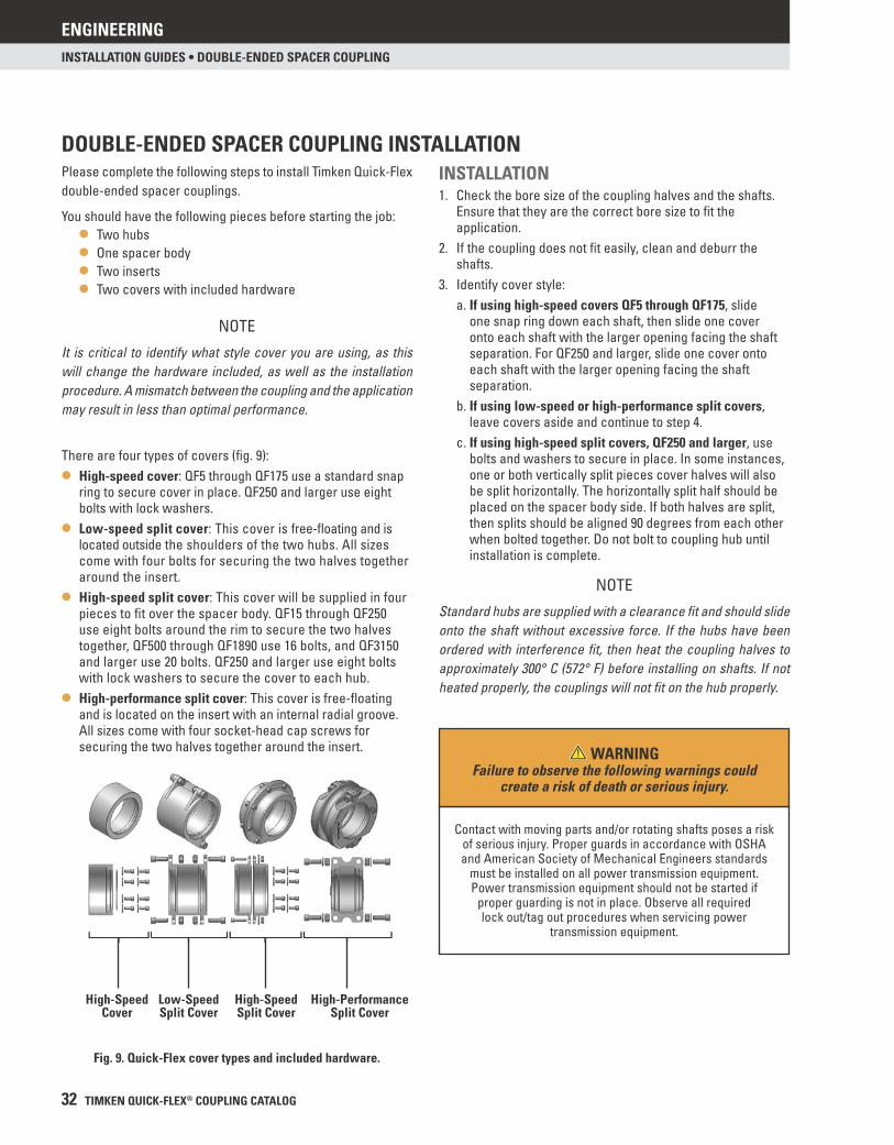
There are four types of covers (fi g. 9):
• High-speed cover: QF5 through QF175 use a standard snap ring to secure cover in place. QF250 and larger use eight bolts with lock washers.
• Low-speed split cover: This cover is free-fl oating and is located outside the shoulders of the two hubs. All sizes come with four bolts for securing the two halves together around the insert.
• High-speed split cover: This cover will be supplied in four pieces to fi t over the spacer body. QF15 through QF250 use eight bolts around the rim to secure the two halves together, QF500 through QF1890 use 16 bolts, and QF3150 and larger use 20 bolts. QF250 and larger use eight bolts with lock washers to secure the cover to each hub.
• High-performance split cover: This cover is free-fl oating and is located on the insert with an internal radial groove. All sizes come with four socket-head cap screws for securing the two halves together around the insert.
DOUBLE-ENDED SPACER COUPLING INSTALLATIONINSTALLATION1. Check the bore size of the coupling halves and the shafts.
Ensure that they are the correct bore size to fi t the application.
2. If the coupling does not fi t easily, clean and deburr the shafts.
3. Identify cover style:a. If using high-speed covers QF5 through QF175, slide
one snap ring down each shaft, then slide one cover onto each shaft with the larger opening facing the shaft separation. For QF250 and larger, slide one cover onto each shaft with the larger opening facing the shaft separation.
b. If using low-speed or high-performance split covers, leave covers aside and continue to step 4.
c. If using high-speed split covers, QF250 and larger, use bolts and washers to secure in place. In some instances, one or both vertically split pieces cover halves will also be split horizontally. The horizontally split half should be placed on the spacer body side. If both halves are split, then splits should be aligned 90 degrees from each other when bolted together. Do not bolt to coupling hub until installation is complete.
NOTE
It is critical to identify what style cover you are using, as this will change the hardware included, as well as the installation procedure. A mismatch between the coupling and the application may result in less than optimal performance.
NOTE
Standard hubs are supplied with a clearance fi t and should slide onto the shaft without excessive force. If the hubs have been ordered with interference fi t, then heat the coupling halves to approximately 300° C (572° F) before installing on shafts. If not heated properly, the couplings will not fi t on the hub properly.
Fig. 9. Quick-Flex cover types and included hardware.
High-Speed Cover
Low-Speed Split Cover
High-Speed Split Cover
High-Performance Split Cover
WARNINGFailure to observe the following warnings could
create a risk of death or serious injury.
Contact with moving parts and/or rotating shafts poses a risk of serious injury. Proper guards in accordance with OSHA and American Society of Mechanical Engineers standards
must be installed on all power transmission equipment. Power transmission equipment should not be started if
proper guarding is not in place. Observe all required lock out/tag out procedures when servicing power
transmission equipment.
ENGINEERING
TIMKEN QUICK-FLEX® COUPLING CATALOG 33
INSTALLATION GUIDES • DOUBLE-ENDED SPACER COUPLING
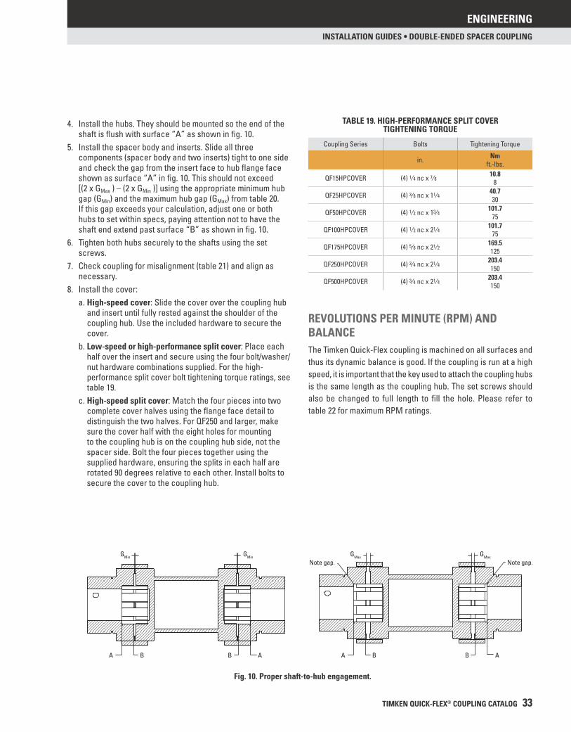
4. Install the hubs. They should be mounted so the end of the shaft is fl ush with surface “A” as shown in fi g. 10.
5. Install the spacer body and inserts. Slide all three components (spacer body and two inserts) tight to one side and check the gap from the insert face to hub fl ange face shown as surface “A” in fi g. 10. This should not exceed [(2 x GMax ) – (2 x GMin )] using the appropriate minimum hub gap (GMin) and the maximum hub gap (GMax) from table 20. If this gap exceeds your calculation, adjust one or both hubs to set within specs, paying attention not to have the shaft end extend past surface “B” as shown in fi g. 10.
6. Tighten both hubs securely to the shafts using the set screws.
7. Check coupling for misalignment (table 21) and align as necessary.
8. Install the cover:a. High-speed cover: Slide the cover over the coupling hub
and insert until fully rested against the shoulder of the coupling hub. Use the included hardware to secure the cover.
b. Low-speed or high-performance split cover: Place each half over the insert and secure using the four bolt/washer/nut hardware combinations supplied. For the high-performance split cover bolt tightening torque ratings, see table 19.
c. High-speed split cover: Match the four pieces into two complete cover halves using the fl ange face detail to distinguish the two halves. For QF250 and larger, make sure the cover half with the eight holes for mounting to the coupling hub is on the coupling hub side, not the spacer side. Bolt the four pieces together using the supplied hardware, ensuring the splits in each half are rotated 90 degrees relative to each other. Install bolts to secure the cover to the coupling hub.
REVOLUTIONS PER MINUTE (RPM) AND BALANCEThe Timken Quick-Flex coupling is machined on all surfaces and thus its dynamic balance is good. If the coupling is run at a high speed, it is important that the key used to attach the coupling hubs is the same length as the coupling hub. The set screws should also be changed to full length to fi ll the hole. Please refer to table 22 for maximum RPM ratings.
Fig. 10. Proper shaft-to-hub engagement.
BA
Note gap. GMax GMin GMin GMax
B A
Note gap.
BA B A
TABLE 19. HIGH-PERFORMANCE SPLIT COVERTIGHTENING TORQUE
Coupling Series Bolts Tightening Torque
in. Nmft.-lbs.
QF15HPCOVER (4) 1⁄4 nc x 7⁄8 10.88
QF25HPCOVER (4) 3⁄8 nc x 11⁄4 40.730
QF50HPCOVER (4) 1⁄2 nc x 13⁄4 101.775
QF100HPCOVER (4) 1⁄2 nc x 21⁄4 101.775
QF175HPCOVER (4) 5⁄8 nc x 21⁄2 169.5125
QF250HPCOVER (4) 3⁄4 nc x 21⁄4 203.4150
QF500HPCOVER (4) 3⁄4 nc x 21⁄4 203.4150

ENGINEERING
34 TIMKEN QUICK-FLEX® COUPLING CATALOG
INSTALLATION GUIDES • DOUBLE-ENDED SPACER COUPLING
TABLE 20. QUICK-FLEX DOUBLE-ENDED SPACER COUPLING HUB GAP (G) DIMENSIONS
CouplingSeries
High-Speed Cover Low-Speed Split Cover High-Speed Split Cover High-Performance Split Cover
GMin GMax GMin GMax GMin GMax GMin GMax
mmin.
mmin.
mmin.
mmin.
mmin.
mmin.
mmin.
mmin.
1.60 2.34N/A N/A N/A N/A N/A N/AQF5 0.063 0.092
0.91 2.79 0.91 2.52 0.91 3.20 0.91 5.59QF15 0.036 0.110 0.036 0.099 0.036 0.126 0.036 0.22
2.03 5.21 2.03 3.38 2.03 3.57 2.03 4.06QF25 0.080 0.205 0.080 0.133 0.080 0.140 0.080 0.16
0.89 5.28 0.89 2.57 0.89 5.59 0.89 4.06QF50 0.035 0.208 0.035 0.101 0.035 0.220 0.035 0.16
3.56 7.37 3.56 9.65 3.56 9.65 3.56 9.40QF100 0.140 0.290 0.140 0.380 0.140 0.380 0.140 0.37
4.78 5.28 4.78 9.53 4.78 8.84 4.57 9.35QF175 0.188 0.208 0.188 0.375 0.188 0.348 0.180 0.368
2.54 5.84 2.54 9.27 2.54 6.35 2.54 8.08QF250 0.100 0.230 0.100 0.365 0.100 0.250 0.100 0.318
3.18 6.35N/A N/A
3.18 9.53 3.18 9.53QF500 0.125 0.250 0.125 0.375 0.125 0.375
4.06 9.86N/A N/A
4.06 10.41N/A N/AQF1000 0.160 0.388 0.160 0.410
5.13 7.06N/A N/A
5.13 11.53N/A N/AQF1890 0.202 0.278 0.202 0.454
1.78 7.75N/A N/A
1.78 9.65N/A N/AQF3150 0.070 0.305 0.070 0.380
3.23 12.83N/A N/A
3.23 12.50N/A N/AQF10260 0.127 0.505 0.127 0.492
DOUBLE-ENDED SPACER COUPLING INSTALLATION – continued

ENGINEERING
TIMKEN QUICK-FLEX® COUPLING CATALOG 35
INSTALLATION GUIDES • DOUBLE-ENDED SPACER COUPLING
TABLE 21. QUICK-FLEX DOUBLE-ENDED SPACER COUPLING MISALIGNMENT TOLERANCES
Coupling Series Radial Misalignment Tolerance Axial Misalignment Tolerance Angular Misalignment Tolerancemmin.
mmin.
QF5 1.02 3.96 4°0.040 0.156
QF15 1.98 5.89 4°0.078 0.232
QF25 1.98 5.89 4°0.078 0.232
QF50 2.95 5.89 4°0.116 0.232
QF100 2.95 7.93 4°0.116 0.312
QF175 2.95 8.89 2.6°0.116 0.350
QF250 2.95 11.89 2.6°0.116 0.468
QF500 2.95 11.89 2°0.116 0.468
QF1000 2.95 11.89 2°0.116 0.468
QF1890 2.95 15.85 2°0.116 0.624
QF3150 3.96 15.85 2°0.156 0.624
QF10260 3.96 15.85 2°0.156 0.624
TABLE 22. QUICK-FLEX DOUBLE-ENDED SPACER MAXIMUM RPM RATINGS(1)
Coupling Series High-Speed Cover Low-Speed Split Cover High-Speed Split Cover High-Performance Split Cover
RPM RPM RPM RPM
QF5 N/A N/A N/A N/A
QF15 4500 400 4500 4500
QF25 4500 375 4500 4500
QF50 4500 350 4500 4500
QF100 4500 300 4500 4500
QF175 3600 250 3600 3600
QF250 3200 200 3200 3200
QF500 3000 N/A 3000 3000
QF1000 2500 N/A 2500 2500
QF1890 2100 N/A 2100 2100
QF3150 1800 N/A 1800 1800
QF10260 1000 N/A 1100 1000
(1)Maximum RPM ratings are for off-the-shelf Quick-Flex couplings. If your application requires higher RPM ratings, the couplings should be dynamically balanced.

ENGINEERING
36 TIMKEN QUICK-FLEX® COUPLING CATALOG
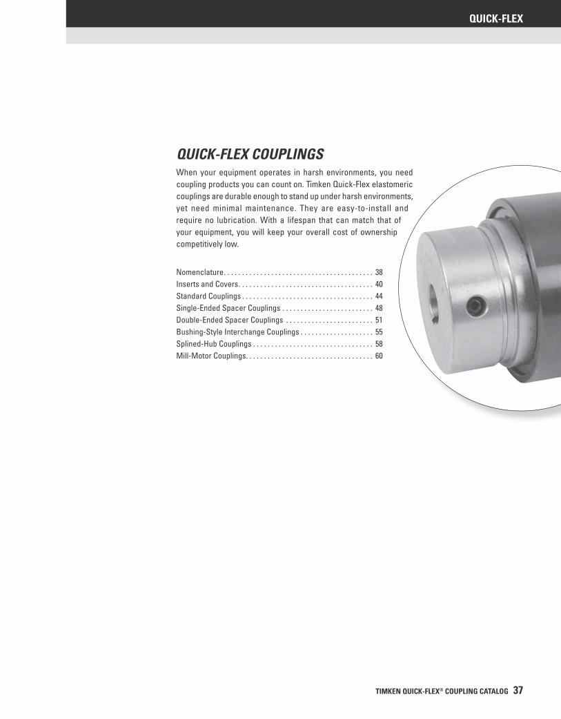
TIMKEN QUICK-FLEX® COUPLING CATALOG 37
QUICK-FLEX
QUICK-FLEX COUPLINGSWhen your equipment operates in harsh environments, you need coupling products you can count on. Timken Quick-Flex elastomeric couplings are durable enough to stand up under harsh environments, yet need minimal maintenance. They are easy-to-install and require no lubrication. With a lifespan that can match that of your equipment, you will keep your overall cost of ownership competitively low.
Nomenclature . . . . . . . . . . . . . . . . . . . . . . . . . . . . . . . . . . . . . . . . . 38 Inserts and Covers . . . . . . . . . . . . . . . . . . . . . . . . . . . . . . . . . . . . . 40Standard Couplings . . . . . . . . . . . . . . . . . . . . . . . . . . . . . . . . . . . . 44Single-Ended Spacer Couplings . . . . . . . . . . . . . . . . . . . . . . . . . 48Double-Ended Spacer Couplings . . . . . . . . . . . . . . . . . . . . . . . . 51Bushing-Style Interchange Couplings . . . . . . . . . . . . . . . . . . . . 55Splined-Hub Couplings . . . . . . . . . . . . . . . . . . . . . . . . . . . . . . . . . 58Mill-Motor Couplings. . . . . . . . . . . . . . . . . . . . . . . . . . . . . . . . . . . 60
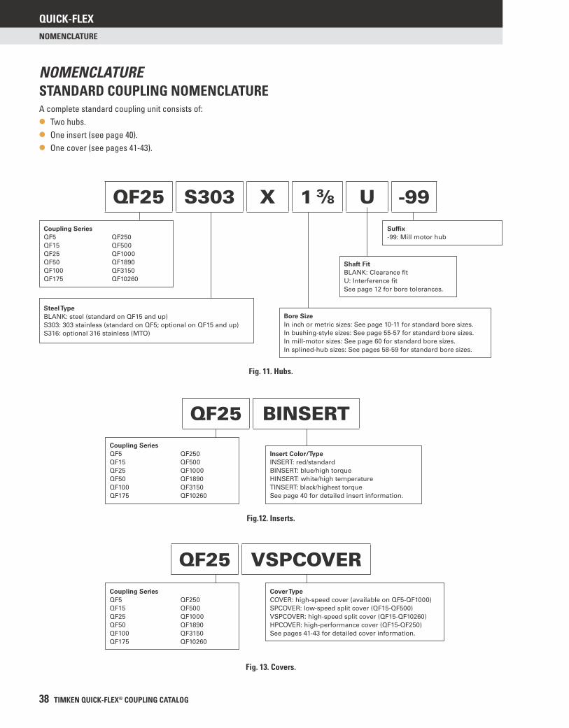
QUICK-FLEX
38 TIMKEN QUICK-FLEX® COUPLING CATALOG
NOMENCLATURE
NOMENCLATURESTANDARD COUPLING NOMENCLATUREA complete standard coupling unit consists of:
• Two hubs.
• One insert (see page 40).
• One cover (see pages 41-43).
QF25 S303 X 1 3⁄8 U -99Coupling SeriesQF5
QF15
QF25
QF50
QF100
QF175
QF250
QF500
QF1000
QF1890
QF3150
QF10260
Steel TypeBLANK: steel (standard on QF15 and up)
S303: 303 stainless (standard on QF5; optional on QF15 and up)
S316: optional 316 stainless (MTO)
Shaft FitBLANK: Clearance fi t
U: Interference fi t
See page 12 for bore tolerances.
Bore SizeIn inch or metric sizes: See page 10-11 for standard bore sizes.
In bushing-style sizes: See page 55-57 for standard bore sizes.
In mill-motor sizes: See page 60 for standard bore sizes.
In splined-hub sizes: See pages 58-59 for standard bore sizes.
Suffi x-99: Mill motor hub
Coupling SeriesQF5
QF15
QF25
QF50
QF100
QF175
QF250
QF500
QF1000
QF1890
QF3150
QF10260
Insert Color/TypeINSERT: red/standard
BINSERT: blue/high torque
HINSERT: white/high temperature
TINSERT: black/highest torque
See page 40 for detailed insert information.
QF25 BINSERT
Coupling SeriesQF5
QF15
QF25
QF50
QF100
QF175
QF250
QF500
QF1000
QF1890
QF3150
QF10260
Cover TypeCOVER: high-speed cover (available on QF5-QF1000)
SPCOVER: low-speed split cover (QF15-QF500)
VSPCOVER: high-speed split cover (QF15-QF10260)
HPCOVER: high-performance cover (QF15-QF250)
See pages 41-43 for detailed cover information.
QF25 VSPCOVER
Fig. 11. Hubs.
Fig.12. Inserts.
Fig. 13. Covers.
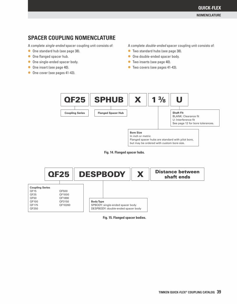
QUICK-FLEX
TIMKEN QUICK-FLEX® COUPLING CATALOG 39
NOMENCLATURE
A complete single-ended spacer coupling unit consists of:
• One standard hub (see page 38).
• One fl anged spacer hub.
• One single-ended spacer body.
• One insert (see page 40).
• One cover (see pages 41-43).
A complete double-ended spacer coupling unit consists of:
• Two standard hubs (see page 38).
• One double-ended spacer body.
• Two inserts (see page 40).
• Two covers (see pages 41-43).
Coupling Series Flanged Spacer Hub
Bore SizeIn inch or metric
Flanged spacer hubs are standard with pilot bore,
but may be ordered with custom bore size.
QF25 SPHUB X 1 3⁄8 UShaft FitBLANK: Clearance fi t
U: Interference fi t
See page 12 for bore tolerances.
Coupling SeriesQF15
QF25
QF50
QF100
QF175
QF250
QF500
QF1000
QF1890
QF3150
QF10260
Body TypeSPBODY: single-ended spacer body
DESPBODY: double-ended spacer body
QF25 DESPBODY X Distance between shaft ends
Fig. 14. Flanged spacer hubs.
Fig. 15. Flanged spacer bodies.
SPACER COUPLING NOMENCLATURE
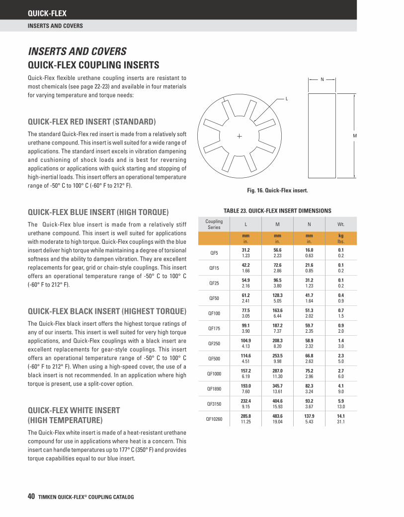
QUICK-FLEX
40 TIMKEN QUICK-FLEX® COUPLING CATALOG
INSERTS AND COVERS
QUICK-FLEX COUPLING INSERTSQuick-Flex fl exible urethane coupling inserts are resistant to most chemicals (see page 22-23) and available in four materials for varying temperature and torque needs:
QUICK-FLEX RED INSERT (STANDARD)The standard Quick-Flex red insert is made from a relatively soft urethane compound. This insert is well suited for a wide range of applications. The standard insert excels in vibration dampening and cushioning of shock loads and is best for reversing applications or applications with quick starting and stopping of high-inertial loads. This insert offers an operational temperature range of -50° C to 100° C (-60° F to 212° F).
QUICK-FLEX BLUE INSERT (HIGH TORQUE)The Quick-Flex blue insert is made from a relatively stiff urethane compound. This insert is well suited for applications with moderate to high torque. Quick-Flex couplings with the blue insert deliver high torque while maintaining a degree of torsional softness and the ability to dampen vibration. They are excellent replacements for gear, grid or chain-style couplings. This insert offers an operational temperature range of -50° C to 100° C (-60° F to 212° F).
QUICK-FLEX BLACK INSERT (HIGHEST TORQUE)The Quick-Flex black insert offers the highest torque ratings of any of our inserts. This insert is well suited for very high torque applications, and Quick-Flex couplings with a black insert are excellent replacements for gear-style couplings. This insert offers an operational temperature range of -50° C to 100° C (-60° F to 212° F). When using a high-speed cover, the use of a black insert is not recommended. In an application where high torque is present, use a split-cover option.
QUICK-FLEX WHITE INSERT (HIGH TEMPERATURE)The Quick-Flex white insert is made of a heat-resistant urethane compound for use in applications where heat is a concern. This insert can handle temperatures up to 177° C (350° F) and provides torque capabilities equal to our blue insert.
TABLE 23. QUICK-FLEX INSERT DIMENSIONS
Coupling Series L M N Wt.
mmin.
mmin.
mmin.
kglbs.
QF5 31.2 56.6 16.0 0.11.23 2.23 0.63 0.2
QF15 42.2 72.6 21.6 0.11.66 2.86 0.85 0.2
QF25 54.9 96.5 31.2 0.12.16 3.80 1.23 0.2
QF50 61.2 128.3 41.7 0.42.41 5.05 1.64 0.9
QF100 77.5 163.6 51.3 0.73.05 6.44 2.02 1.5
QF175 99.1 187.2 59.7 0.93.90 7.37 2.35 2.0
QF250 104.9 208.3 58.9 1.44.13 8.20 2.32 3.0
QF500 114.6 253.5 66.8 2.34.51 9.98 2.63 5.0
QF1000 157.2 287.0 75.2 2.76.19 11.30 2.96 6.0
QF1890 193.0 345.7 82.3 4.17.60 13.61 3.24 9.0
QF3150 232.4 404.6 93.2 5.99.15 15.93 3.67 13.0
QF10260 285.8 483.6 137.9 14.111.25 19.04 5.43 31.1
INSERTS AND COVERS
Fig. 16. Quick-Flex insert.
L
N
M
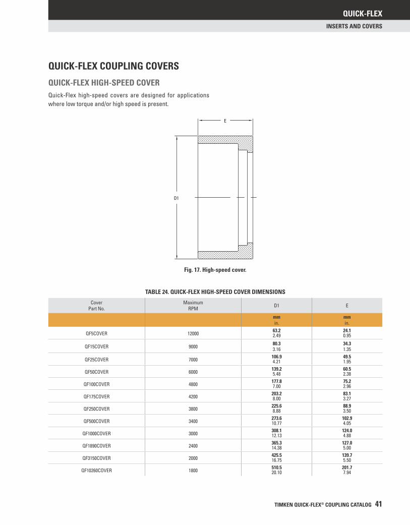
QUICK-FLEX
TIMKEN QUICK-FLEX® COUPLING CATALOG 41
INSERTS AND COVERS
QUICK-FLEX COUPLING COVERS
QUICK-FLEX HIGH-SPEED COVERQuick-Flex high-speed covers are designed for applications where low torque and/or high speed is present.
Fig. 17. High-speed cover.
E
D1
TABLE 24. QUICK-FLEX HIGH-SPEED COVER DIMENSIONS
Cover Part No.
Maximum RPM D1 E
mmin.
mmin.
QF5COVER 12000 63.2 24.12.49 0.95
QF15COVER 9000 80.3 34.33.16 1.35
QF25COVER 7000 106.9 49.54.21 1.95
QF50COVER 6000 139.2 60.55.48 2.38
QF100COVER 4800 177.8 75.27.00 2.96
QF175COVER 4200 203.2 83.18.00 3.27
QF250COVER 3800 225.6 88.98.88 3.50
QF500COVER 3400 273.6 102.910.77 4.05
QF1000COVER 3000 308.1 124.012.13 4.88
QF1890COVER 2400 365.3 127.014.38 5.00
QF3150COVER 2000 425.5 139.716.75 5.50
QF10260COVER 1800 510.5 201.720.10 7.94
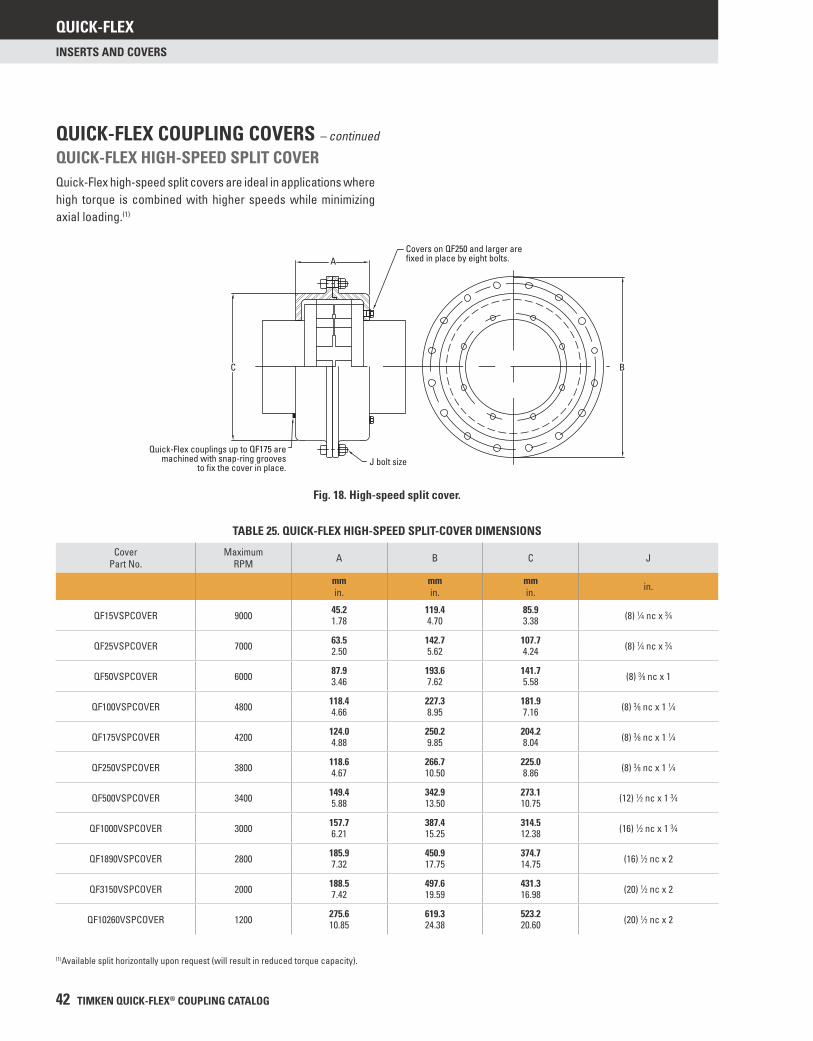
QUICK-FLEX
42 TIMKEN QUICK-FLEX® COUPLING CATALOG
INSERTS AND COVERS
Fig. 18. High-speed split cover.
QUICK-FLEX HIGH-SPEED SPLIT COVERQuick-Flex high-speed split covers are ideal in applications where high torque is combined with higher speeds while minimizing axial loading.(1)
TABLE 25. QUICK-FLEX HIGH-SPEED SPLIT-COVER DIMENSIONS
Cover Part No.
Maximum RPM A B C J
mmin.
mmin.
mmin. in.
QF15VSPCOVER 9000 45.2 119.4 85.9 (8) 1⁄4 nc x 3⁄41.78 4.70 3.38
QF25VSPCOVER 7000 63.5 142.7 107.7 (8) 1⁄4 nc x 3⁄42.50 5.62 4.24
QF50VSPCOVER 6000 87.9 193.6 141.7 (8) 3⁄8 nc x 13.46 7.62 5.58
QF100VSPCOVER 4800 118.4 227.3 181.9 (8) 3⁄8 nc x 1 1⁄44.66 8.95 7.16
QF175VSPCOVER 4200 124.0 250.2 204.2 (8) 3⁄8 nc x 1 1⁄44.88 9.85 8.04
QF250VSPCOVER 3800 118.6 266.7 225.0 (8) 3⁄8 nc x 1 1⁄44.67 10.50 8.86
QF500VSPCOVER 3400 149.4 342.9 273.1 (12) 1⁄2 nc x 1 3⁄45.88 13.50 10.75
QF1000VSPCOVER 3000 157.7 387.4 314.5 (16) 1⁄2 nc x 1 3⁄46.21 15.25 12.38
QF1890VSPCOVER 2800 185.9 450.9 374.7 (16) 1⁄2 nc x 27.32 17.75 14.75
QF3150VSPCOVER 2000 188.5 497.6 431.3 (20) 1⁄2 nc x 27.42 19.59 16.98
QF10260VSPCOVER 1200 275.6 619.3 523.2 (20) 1⁄2 nc x 210.85 24.38 20.60
(1)Available split horizontally upon request (will result in reduced torque capacity).
A
C B
J bolt size
Covers on QF250 and larger are fixed in place by eight bolts.
Quick-Flex couplings up to QF175 aremachined with snap-ring grooves
to fix the cover in place.
QUICK-FLEX COUPLING COVERS – continued
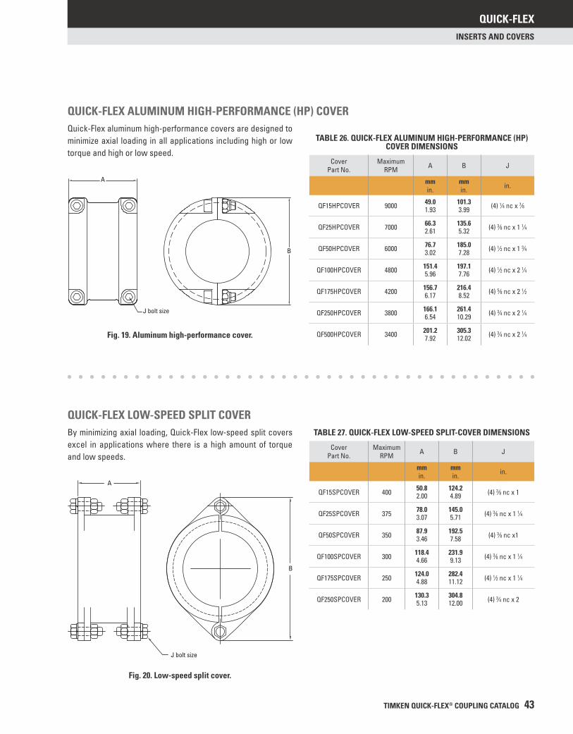
QUICK-FLEX
TIMKEN QUICK-FLEX® COUPLING CATALOG 43
INSERTS AND COVERS
QUICK-FLEX ALUMINUM HIGH-PERFORMANCE (HP) COVERQuick-Flex aluminum high-performance covers are designed to minimize axial loading in all applications including high or low torque and high or low speed.
Fig. 19. Aluminum high-performance cover.
TABLE 26. QUICK-FLEX ALUMINUM HIGH-PERFORMANCE (HP) COVER DIMENSIONS
Cover Part No.
Maximum RPM A B J
mmin.
mmin. in.
QF15HPCOVER 9000 49.0 101.3 (4) 1⁄4 nc x 7⁄81.93 3.99
QF25HPCOVER 7000 66.3 135.6 (4) 3⁄8 nc x 1 1⁄42.61 5.32
QF50HPCOVER 6000 76.7 185.0 (4) 1⁄2 nc x 1 3⁄43.02 7.28
QF100HPCOVER 4800 151.4 197.1 (4) 1⁄2 nc x 2 1⁄45.96 7.76
QF175HPCOVER 4200 156.7 216.4 (4) 5⁄8 nc x 2 1⁄26.17 8.52
QF250HPCOVER 3800 166.1 261.4 (4) 3⁄4 nc x 2 1⁄46.54 10.29
QF500HPCOVER 3400 201.2 305.3 (4) 3⁄4 nc x 2 1⁄47.92 12.02
Fig. 20. Low-speed split cover.
QUICK-FLEX LOW-SPEED SPLIT COVERBy minimizing axial loading, Quick-Flex low-speed split covers excel in applications where there is a high amount of torque and low speeds.
TABLE 27. QUICK-FLEX LOW-SPEED SPLIT-COVER DIMENSIONS
Cover Part No.
Maximum RPM A B J
mmin.
mmin. in.
QF15SPCOVER 400 50.8 124.2 (4) 3⁄8 nc x 12.00 4.89
QF25SPCOVER 375 78.0 145.0 (4) 3⁄8 nc x 1 1⁄43.07 5.71
QF50SPCOVER 350 87.9 192.5 (4) 3⁄8 nc x13.46 7.58
QF100SPCOVER 300 118.4 231.9 (4) 3⁄8 nc x 1 1⁄44.66 9.13
QF175SPCOVER 250 124.0 282.4 (4) 1⁄2 nc x 1 1⁄44.88 11.12
QF250SPCOVER 200 130.3 304.8 (4) 3⁄4 nc x 25.13 12.00
A
B
J bolt size
B
A
J bolt size
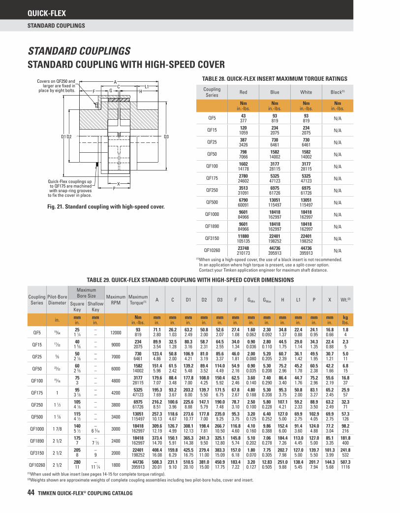
QUICK-FLEX
44 TIMKEN QUICK-FLEX® COUPLING CATALOG
STANDARD COUPLINGS
STANDARD COUPLING WITH HIGH-SPEED COVERSTANDARD COUPLINGS
TABLE 29. QUICK-FLEX STANDARD COUPLING WITH HIGH-SPEED COVER DIMENSIONS
CouplingSeries
Pilot-BoreDiameter
Maximum Bore Size Maximum
RPMMaximum Torque(1) A C D1 D2 D3 F GMin GMax H L1 P X Wt.(2)
Square Key
Shallow Key
in. mmin.
mmin.
Nmin.-lbs.
mmin.
mmin.
mmin.
mmin.
mmin.
mmin.
mmin.
mmin.
mmin.
mmin.
mmin.
mmin.
kglbs.
QF5 19⁄6425 – 12000 93 71.1 26.2 63.2 50.8 52.6 27.4 1.60 2.30 34.8 22.4 24.1 16.8 1.8
1 1⁄4 – 819 2.80 1.03 2.49 2.00 2.07 1.08 0.062 0.092 1.37 0.88 0.95 0.66 4
QF15 17⁄3240 – 9000 234 89.9 32.5 80.3 58.7 64.5 34.0 0.90 2.80 44.5 29.0 34.3 22.4 2.3
1 5⁄8 – 2075 3.54 1.28 3.16 2.31 2.55 1.34 0.036 0.110 1.75 1.14 1.35 0.88 5
QF25 5⁄8 50 – 7000 730 123.4 50.8 106.9 81.0 85.6 46.0 2.00 5.20 60.7 36.1 49.5 30.7 5.02 1⁄8 – 6461 4.86 2.00 4.21 3.19 3.37 1.81 0.080 0.205 2.39 1.42 1.95 1.21 11
QF50 23⁄3260 – 6000 1582 151.4 61.5 139.2 89.4 114.0 54.9 0.90 5.30 75.2 45.2 60.5 42.2 6.8
2 3⁄8 – 14002 5.96 2.42 5.48 3.52 4.49 2.16 0.035 0.208 2.96 1.78 2.38 1.66 15
QF100 15⁄1675 – 4800 3177 179.6 88.4 177.8 108.0 150.4 62.5 3.60 7.40 86.4 44.7 75.2 55.6 16.83 – 28115 7.07 3.48 7.00 4.25 5.92 2.46 0.140 0.290 3.40 1.76 2.96 2.19 37
QF175 1 95 – 4200 5325 195.3 93.2 203.2 139.7 171.5 67.8 4.80 5.30 95.3 50.8 83.1 65.2 25.93 7⁄8 – 47123 7.69 3.67 8.00 5.50 6.75 2.67 0.188 0.208 3.75 2.00 3.27 2.45 57
QF250 1 1⁄2 105 – 3800 6975 216.2 100.6 225.6 147.1 190.0 78.7 2.50 5.80 107.1 59.2 88.9 63.2 32.34 1⁄8 – 61726 8.51 3.96 8.88 5.79 7.48 3.10 0.100 0.228 4.21 2.33 3.50 2.49 71
QF500 1 7⁄8 115 – 3400 13051 257.3 118.6 273.6 177.8 235.0 95.3 3.20 6.40 127.0 69.9 102.9 69.9 57.34 1⁄2 – 115497 10.13 4.67 10.77 7.00 9.25 3.75 0.125 0.252 5.00 2.75 4.05 2.75 126
QF1000 1 7/8 140 – 3000 18418 309.6 126.7 308.1 198.4 266.7 116.8 4.10 9.86 152.4 91.4 124.0 77.2 98.25 1⁄2 6 3⁄16 162997 12.19 4.99 12.13 7.81 10.50 4.60 0.160 0.388 6.00 3.60 4.88 3.04 216
QF1890 2 1/2 175 – 2400 18418 373.4 150.1 365.3 241.3 325.1 145.8 5.10 7.06 184.4 113.0 127.0 85.1 181.87 7 1⁄2 162997 14.70 5.91 14.38 9.50 12.80 5.74 0.202 0.278 7.26 4.45 5.00 3.35 400
QF3150 2 1/2 205 – 2000 22401 408.4 159.8 425.5 279.4 383.3 157.0 1.80 7.75 202.7 127.0 139.7 101.3 241.88 9 198252 16.08 6.29 16.75 11.00 15.09 6.18 0.070 0.305 7.98 5.00 5.50 3.99 532
QF10260 2 1/2 280 – 1800 44736 508.3 231.1 510.5 381.0 450.9 183.4 3.20 12.83 251.0 138.4 201.7 144.3 507.311 11 1⁄4 395913 20.01 9.10 20.10 15.00 17.75 7.22 0.127 0.505 9.88 5.45 7.94 5.68 1116
(1)When used with blue insert (see pages 14-15 for complete torque ratings).(2)Weights shown are approximate weights of complete coupling assemblies including two pilot-bore hubs, cover and insert.
Fig. 21. Standard coupling with high-speed cover.
P
C
D2D1
AL1
HF
X
Covers on QF250 andlarger are fixed in
place by eight bolts.
D3
Quick-Flex couplings upto QF175 are machinedwith snap-ring grooves
to fix the cover in place.
G
TABLE 28. QUICK-FLEX INSERT MAXIMUM TORQUE RATINGS
Coupling Series Red Blue White Black(1)
Nmin.-lbs.
Nmin.-lbs.
Nmin.-lbs.
Nmin.-lbs.
43 93 93 N/AQF5 377 819 819120 234 234 N/AQF15 1059 2075 2075387 730 730 N/AQF25 3426 6461 6461798 1582 1582 N/AQF50 7066 14002 14002
1602 3177 3177 N/AQF100 14178 28115 281152780 5325 5325 N/AQF175 24602 47123 471233513 6975 6975 N/AQF250 31091 61726 617266790 13051 13051 N/AQF500 60091 115497 1154979601 18418 18418 N/AQF1000 84966 162997 1629979601 18418 18418 N/AQF1890 84966 162997 162997
11880 22401 22401 N/AQF3150 105135 198252 19825223748 44736 44736 N/AQF10260 210173 395913 395913
(1) When using a high-speed cover, the use of a black insert is not recommended. In an application where high torque is present, use a split-cover option. Contact your Timken application engineer for maximum shaft distance.
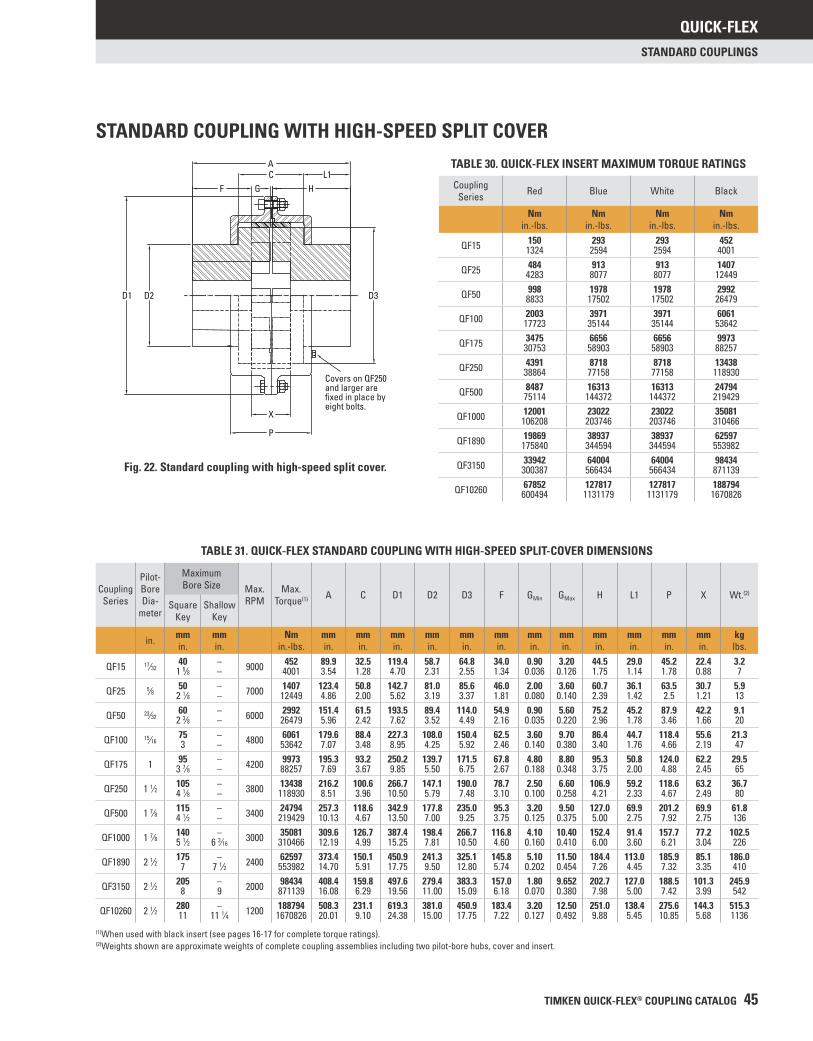
QUICK-FLEX
TIMKEN QUICK-FLEX® COUPLING CATALOG 45
STANDARD COUPLINGS
STANDARD COUPLING WITH HIGH-SPEED SPLIT COVER
TABLE 31. QUICK-FLEX STANDARD COUPLING WITH HIGH-SPEED SPLIT-COVER DIMENSIONS
CouplingSeries
Pilot-Bore Dia-
meter
Maximum Bore Size Max.
RPMMax.
Torque(1) A C D1 D2 D3 F GMin GMax H L1 P X Wt.(2)
Square Key
Shallow Key
in. mmin.
mmin.
Nmin.-lbs.
mmin.
mmin.
mmin.
mmin.
mmin.
mmin.
mmin.
mmin.
mmin.
mmin.
mmin.
mmin.
kglbs.
QF15 17⁄3240 – 9000 452 89.9 32.5 119.4 58.7 64.8 34.0 0.90 3.20 44.5 29.0 45.2 22.4 3.2
1 5⁄8 – 4001 3.54 1.28 4.70 2.31 2.55 1.34 0.036 0.126 1.75 1.14 1.78 0.88 7
QF25 5⁄8 50 – 7000 1407 123.4 50.8 142.7 81.0 85.6 46.0 2.00 3.60 60.7 36.1 63.5 30.7 5.92 1⁄8 – 12449 4.86 2.00 5.62 3.19 3.37 1.81 0.080 0.140 2.39 1.42 2.5 1.21 13
QF50 23⁄3260 – 6000 2992 151.4 61.5 193.5 89.4 114.0 54.9 0.90 5.60 75.2 45.2 87.9 42.2 9.1
2 3⁄8 – 26479 5.96 2.42 7.62 3.52 4.49 2.16 0.035 0.220 2.96 1.78 3.46 1.66 20
QF100 15⁄1675 – 4800 6061 179.6 88.4 227.3 108.0 150.4 62.5 3.60 9.70 86.4 44.7 118.4 55.6 21.33 – 53642 7.07 3.48 8.95 4.25 5.92 2.46 0.140 0.380 3.40 1.76 4.66 2.19 47
QF175 1 95 – 4200 9973 195.3 93.2 250.2 139.7 171.5 67.8 4.80 8.80 95.3 50.8 124.0 62.2 29.53 7⁄8 – 88257 7.69 3.67 9.85 5.50 6.75 2.67 0.188 0.348 3.75 2.00 4.88 2.45 65
QF250 1 1⁄2 105 – 3800 13438 216.2 100.6 266.7 147.1 190.0 78.7 2.50 6.60 106.9 59.2 118.6 63.2 36.74 1⁄8 – 118930 8.51 3.96 10.50 5.79 7.48 3.10 0.100 0.258 4.21 2.33 4.67 2.49 80
QF500 1 7⁄8 115 – 3400 24794 257.3 118.6 342.9 177.8 235.0 95.3 3.20 9.50 127.0 69.9 201.2 69.9 61.84 1⁄2 – 219429 10.13 4.67 13.50 7.00 9.25 3.75 0.125 0.375 5.00 2.75 7.92 2.75 136
QF1000 1 7⁄8 140 – 3000 35081 309.6 126.7 387.4 198.4 266.7 116.8 4.10 10.40 152.4 91.4 157.7 77.2 102.55 1⁄2 6 3⁄16 310466 12.19 4.99 15.25 7.81 10.50 4.60 0.160 0.410 6.00 3.60 6.21 3.04 226
QF1890 2 1⁄2 175 – 2400 62597 373.4 150.1 450.9 241.3 325.1 145.8 5.10 11.50 184.4 113.0 185.9 85.1 186.07 7 1⁄2 553982 14.70 5.91 17.75 9.50 12.80 5.74 0.202 0.454 7.26 4.45 7.32 3.35 410
QF3150 2 1⁄2 205 – 2000 98434 408.4 159.8 497.6 279.4 383.3 157.0 1.80 9.652 202.7 127.0 188.5 101.3 245.98 9 871139 16.08 6.29 19.56 11.00 15.09 6.18 0.070 0.380 7.98 5.00 7.42 3.99 542
QF10260 2 1⁄2 280 – 1200 188794 508.3 231.1 619.3 381.0 450.9 183.4 3.20 12.50 251.0 138.4 275.6 144.3 515.311 11 1⁄4 1670826 20.01 9.10 24.38 15.00 17.75 7.22 0.127 0.492 9.88 5.45 10.85 5.68 1136
(1)When used with black insert (see pages 16-17 for complete torque ratings).(2)Weights shown are approximate weights of complete coupling assemblies including two pilot-bore hubs, cover and insert.
Fig. 22. Standard coupling with high-speed split cover.
AC L1
F G H
D3
Covers on QF250 and larger are fixed in place by eight bolts.
D1 D2
X
P
TABLE 30. QUICK-FLEX INSERT MAXIMUM TORQUE RATINGS
Coupling Series Red Blue White Black
Nmin.-lbs.
Nmin.-lbs.
Nmin.-lbs.
Nmin.-lbs.
150 293 293 452QF15 1324 2594 2594 4001484 913 913 1407QF25 4283 8077 8077 12449998 1978 1978 2992QF50 8833 17502 17502 26479
2003 3971 3971 6061QF100 17723 35144 35144 536423475 6656 6656 9973QF175 30753 58903 58903 882574391 8718 8718 13438QF250 38864 77158 77158 1189308487 16313 16313 24794QF500 75114 144372 144372 219429
12001 23022 23022 35081QF1000 106208 203746 203746 31046619869 38937 38937 62597QF1890 175840 344594 344594 55398233942 64004 64004 98434QF3150 300387 566434 566434 87113967852 127817 127817 188794QF10260 600494 1131179 1131179 1670826
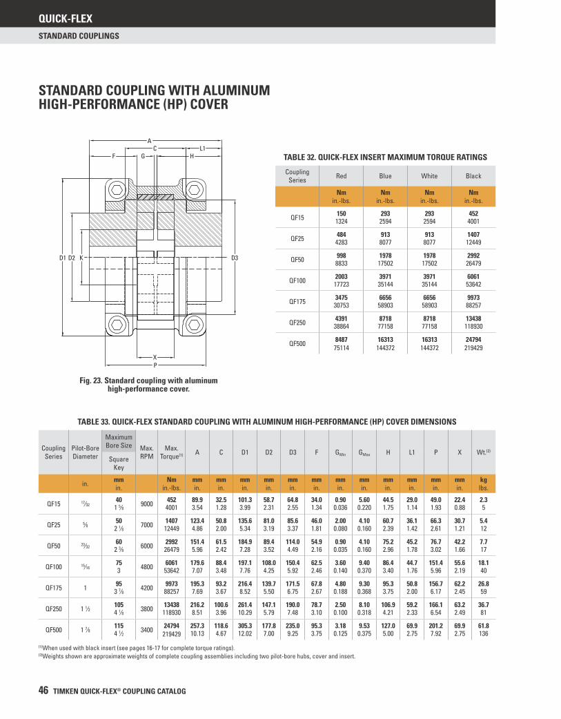
QUICK-FLEX
46 TIMKEN QUICK-FLEX® COUPLING CATALOG
STANDARD COUPLINGS
AC L1
F G H
KD2D1 D3
XP
STANDARD COUPLING WITH ALUMINUM HIGH-PERFORMANCE (HP) COVER
Fig. 23. Standard coupling with aluminum high-performance cover.
TABLE 33. QUICK-FLEX STANDARD COUPLING WITH ALUMINUM HIGH-PERFORMANCE (HP) COVER DIMENSIONS
Coupling Series
Pilot-Bore Diameter
Maximum Bore Size Max.
RPMMax.
Torque(1) A C D1 D2 D3 F GMin GMax H L1 P X Wt.(2)
Square Key
in. mmin.
Nmin.-lbs.
mmin.
mmin.
mmin.
mmin.
mmin.
mmin.
mmin.
mmin.
mmin.
mmin.
mmin.
mmin.
kglbs.
QF15 17⁄3240 9000 452 89.9 32.5 101.3 58.7 64.8 34.0 0.90 5.60 44.5 29.0 49.0 22.4 2.3
1 5⁄8 4001 3.54 1.28 3.99 2.31 2.55 1.34 0.036 0.220 1.75 1.14 1.93 0.88 5
QF25 5⁄8 50 7000 1407 123.4 50.8 135.6 81.0 85.6 46.0 2.00 4.10 60.7 36.1 66.3 30.7 5.42 1⁄8 12449 4.86 2.00 5.34 3.19 3.37 1.81 0.080 0.160 2.39 1.42 2.61 1.21 12
QF50 23⁄3260 6000 2992 151.4 61.5 184.9 89.4 114.0 54.9 0.90 4.10 75.2 45.2 76.7 42.2 7.7
2 3⁄8 26479 5.96 2.42 7.28 3.52 4.49 2.16 0.035 0.160 2.96 1.78 3.02 1.66 17
QF100 15⁄1675 4800 6061 179.6 88.4 197.1 108.0 150.4 62.5 3.60 9.40 86.4 44.7 151.4 55.6 18.13 53642 7.07 3.48 7.76 4.25 5.92 2.46 0.140 0.370 3.40 1.76 5.96 2.19 40
QF175 1 95 4200 9973 195.3 93.2 216.4 139.7 171.5 67.8 4.80 9.30 95.3 50.8 156.7 62.2 26.83 7⁄8 88257 7.69 3.67 8.52 5.50 6.75 2.67 0.188 0.368 3.75 2.00 6.17 2.45 59
QF250 1 1⁄2 105 3800 13438 216.2 100.6 261.4 147.1 190.0 78.7 2.50 8.10 106.9 59.2 166.1 63.2 36.74 1⁄8 118930 8.51 3.96 10.29 5.79 7.48 3.10 0.100 0.318 4.21 2.33 6.54 2.49 81
QF500 1 7⁄8 115 3400 24794 257.3 118.6 305.3 177.8 235.0 95.3 3.18 9.53 127.0 69.9 201.2 69.9 61.84 1⁄2 219429 10.13 4.67 12.02 7.00 9.25 3.75 0.125 0.375 5.00 2.75 7.92 2.75 136
(1)When used with black insert (see pages 16-17 for complete torque ratings).(2)Weights shown are approximate weights of complete coupling assemblies including two pilot-bore hubs, cover and insert.
TABLE 32. QUICK-FLEX INSERT MAXIMUM TORQUE RATINGS
Coupling Series Red Blue White Black
Nmin.-lbs.
Nmin.-lbs.
Nmin.-lbs.
Nmin.-lbs.
150 293 293 452QF15 1324 2594 2594 4001
484 913 913 1407QF25 4283 8077 8077 12449
998 1978 1978 2992QF50 8833 17502 17502 26479
2003 3971 3971 6061QF100 17723 35144 35144 53642
3475 6656 6656 9973QF175 30753 58903 58903 88257
4391 8718 8718 13438QF250 38864 77158 77158 118930
8487 16313 16313 24794QF500 75114 144372 144372 219429
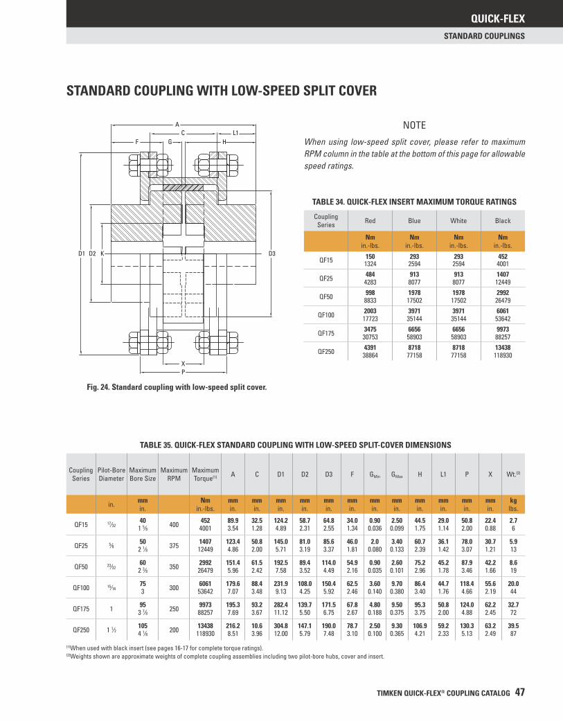
QUICK-FLEX
TIMKEN QUICK-FLEX® COUPLING CATALOG 47
STANDARD COUPLINGS
STANDARD COUPLING WITH LOW-SPEED SPLIT COVER
Fig. 24. Standard coupling with low-speed split cover.
TABLE 34. QUICK-FLEX INSERT MAXIMUM TORQUE RATINGS
Coupling Series Red Blue White Black
Nmin.-lbs.
Nmin.-lbs.
Nmin.-lbs.
Nmin.-lbs.
150 293 293 452QF15 1324 2594 2594 4001484 913 913 1407QF25 4283 8077 8077 12449998 1978 1978 2992QF50 8833 17502 17502 26479
2003 3971 3971 6061QF100 17723 35144 35144 536423475 6656 6656 9973QF175 30753 58903 58903 882574391 8718 8718 13438QF250 38864 77158 77158 118930
TABLE 35. QUICK-FLEX STANDARD COUPLING WITH LOW-SPEED SPLIT-COVER DIMENSIONS
CouplingSeries
Pilot-BoreDiameter
MaximumBore Size
MaximumRPM
MaximumTorque(1) A C D1 D2 D3 F GMin GMax H L1 P X Wt.(2)
in. mmin.
Nmin.-lbs.
mmin.
mmin.
mmin.
mmin.
mmin.
mmin.
mmin.
mmin.
mmin.
mmin.
mmin.
mmin.
kglbs.
QF15 17⁄3240 400 452 89.9 32.5 124.2 58.7 64.8 34.0 0.90 2.50 44.5 29.0 50.8 22.4 2.7
1 5⁄8 4001 3.54 1.28 4.89 2.31 2.55 1.34 0.036 0.099 1.75 1.14 2.00 0.88 6
QF25 5⁄8 50 375 1407 123.4 50.8 145.0 81.0 85.6 46.0 2.0 3.40 60.7 36.1 78.0 30.7 5.92 1⁄8 12449 4.86 2.00 5.71 3.19 3.37 1.81 0.080 0.133 2.39 1.42 3.07 1.21 13
QF50 23⁄3260 350 2992 151.4 61.5 192.5 89.4 114.0 54.9 0.90 2.60 75.2 45.2 87.9 42.2 8.6
2 3⁄8 26479 5.96 2.42 7.58 3.52 4.49 2.16 0.035 0.101 2.96 1.78 3.46 1.66 19
QF100 15⁄1675 300 6061 179.6 88.4 231.9 108.0 150.4 62.5 3.60 9.70 86.4 44.7 118.4 55.6 20.03 53642 7.07 3.48 9.13 4.25 5.92 2.46 0.140 0.380 3.40 1.76 4.66 2.19 44
QF175 1 95 250 9973 195.3 93.2 282.4 139.7 171.5 67.8 4.80 9.50 95.3 50.8 124.0 62.2 32.73 7⁄8 88257 7.69 3.67 11.12 5.50 6.75 2.67 0.188 0.375 3.75 2.00 4.88 2.45 72
QF250 1 1⁄2 105 200 13438 216.2 10.6 304.8 147.1 190.0 78.7 2.50 9.30 106.9 59.2 130.3 63.2 39.54 1⁄8 118930 8.51 3.96 12.00 5.79 7.48 3.10 0.100 0.365 4.21 2.33 5.13 2.49 87
(1)When used with black insert (see pages 16-17 for complete torque ratings).(2)Weights shown are approximate weights of complete coupling assemblies including two pilot-bore hubs, cover and insert.
AC L1
HGF
D1 D2 D3K
XP
NOTE
When using low-speed split cover, please refer to maximum RPM column in the table at the bottom of this page for allowable speed ratings.
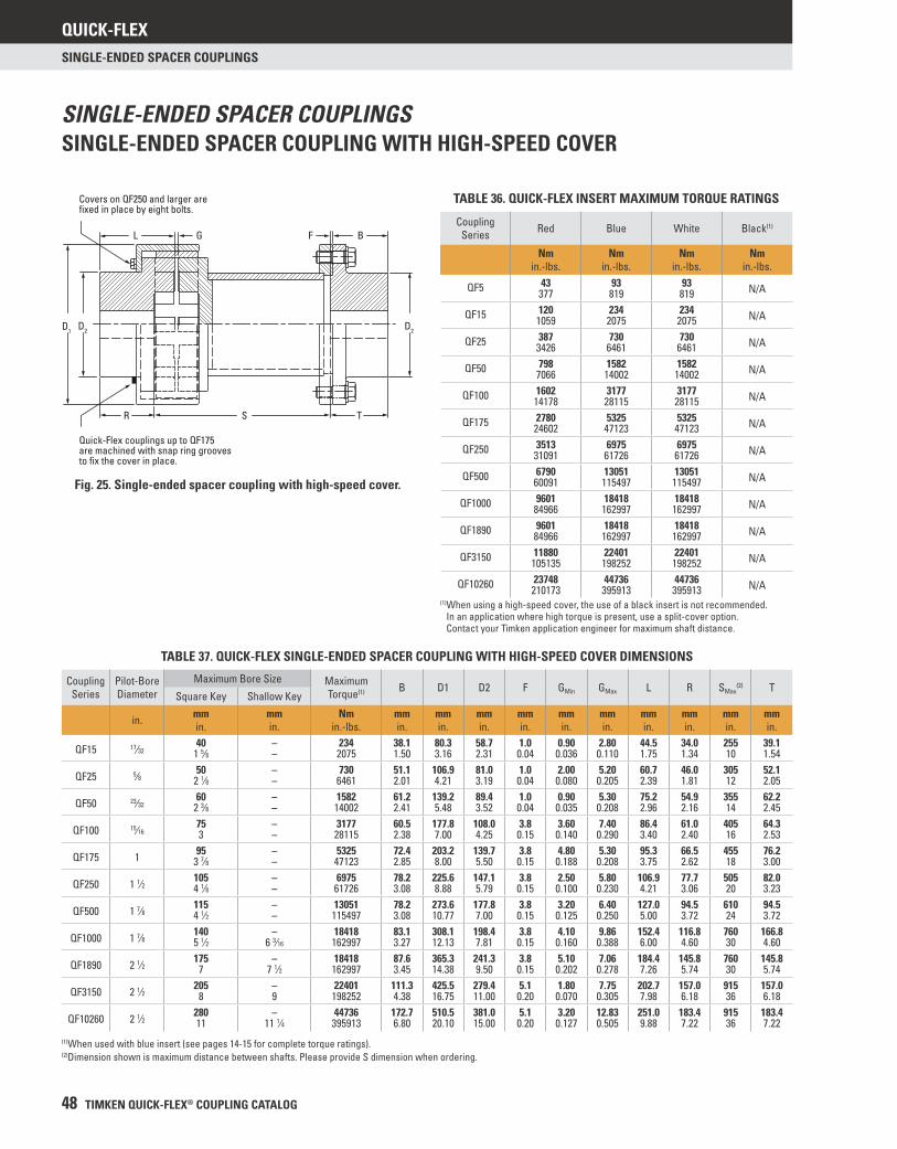
QUICK-FLEX
48 TIMKEN QUICK-FLEX® COUPLING CATALOG
SINGLE-ENDED SPACER COUPLINGS
BL
D1
Quick-Flex couplings up to QF175 are machined with snap ring grooves to fix the cover in place.
Covers on QF250 and larger are fixed in place by eight bolts.
D2
G
R S
D2
F
T
SINGLE-ENDED SPACER COUPLINGSSINGLE-ENDED SPACER COUPLING WITH HIGH-SPEED COVER
TABLE 37. QUICK-FLEX SINGLE-ENDED SPACER COUPLING WITH HIGH-SPEED COVER DIMENSIONS
Coupling Series
Pilot-Bore Diameter
Maximum Bore Size Maximum Torque(1) B D1 D2 F GMin GMax L R SMax
(2) TSquare Key Shallow Key
in. mmin.
mmin.
Nmin.-lbs.
mmin.
mmin.
mmin.
mmin.
mmin.
mmin.
mmin.
mmin.
mmin.
mmin.
QF15 17⁄3240 – 234 38.1 80.3 58.7 1.0 0.90 2.80 44.5 34.0 255 39.1
1 5⁄8 – 2075 1.50 3.16 2.31 0.04 0.036 0.110 1.75 1.34 10 1.54
QF25 5⁄8 50 – 730 51.1 106.9 81.0 1.0 2.00 5.20 60.7 46.0 305 52.12 1⁄8 – 6461 2.01 4.21 3.19 0.04 0.080 0.205 2.39 1.81 12 2.05
QF50 23⁄3260 – 1582 61.2 139.2 89.4 1.0 0.90 5.30 75.2 54.9 355 62.2
2 3⁄8 – 14002 2.41 5.48 3.52 0.04 0.035 0.208 2.96 2.16 14 2.45
QF100 15⁄1675 – 3177 60.5 177.8 108.0 3.8 3.60 7.40 86.4 61.0 405 64.33 – 28115 2.38 7.00 4.25 0.15 0.140 0.290 3.40 2.40 16 2.53
QF175 1 95 – 5325 72.4 203.2 139.7 3.8 4.80 5.30 95.3 66.5 455 76.23 7⁄8 – 47123 2.85 8.00 5.50 0.15 0.188 0.208 3.75 2.62 18 3.00
QF250 1 1⁄2 105 – 6975 78.2 225.6 147.1 3.8 2.50 5.80 106.9 77.7 505 82.04 1⁄8 – 61726 3.08 8.88 5.79 0.15 0.100 0.230 4.21 3.06 20 3.23
QF500 1 7⁄8 115 – 13051 78.2 273.6 177.8 3.8 3.20 6.40 127.0 94.5 610 94.54 1⁄2 – 115497 3.08 10.77 7.00 0.15 0.125 0.250 5.00 3.72 24 3.72
QF1000 1 7⁄8 140 – 18418 83.1 308.1 198.4 3.8 4.10 9.86 152.4 116.8 760 166.85 1⁄2 6 3⁄16 162997 3.27 12.13 7.81 0.15 0.160 0.388 6.00 4.60 30 4.60
QF1890 2 1⁄2 175 – 18418 87.6 365.3 241.3 3.8 5.10 7.06 184.4 145.8 760 145.87 7 1⁄2 162997 3.45 14.38 9.50 0.15 0.202 0.278 7.26 5.74 30 5.74
QF3150 2 1⁄2 205 – 22401 111.3 425.5 279.4 5.1 1.80 7.75 202.7 157.0 915 157.08 9 198252 4.38 16.75 11.00 0.20 0.070 0.305 7.98 6.18 36 6.18
QF10260 2 1⁄2 280 – 44736 172.7 510.5 381.0 5.1 3.20 12.83 251.0 183.4 915 183.411 11 1⁄4 395913 6.80 20.10 15.00 0.20 0.127 0.505 9.88 7.22 36 7.22
(1)When used with blue insert (see pages 14-15 for complete torque ratings).(2)Dimension shown is maximum distance between shafts. Please provide S dimension when ordering.
Fig. 25. Single-ended spacer coupling with high-speed cover.
TABLE 36. QUICK-FLEX INSERT MAXIMUM TORQUE RATINGS
Coupling Series Red Blue White Black(1)
Nmin.-lbs.
Nmin.-lbs.
Nmin.-lbs.
Nmin.-lbs.
43 93 93 N/AQF5 377 819 819120 234 234 N/AQF15 1059 2075 2075387 730 730 N/AQF25 3426 6461 6461798 1582 1582 N/AQF50 7066 14002 14002
1602 3177 3177 N/AQF100 14178 28115 281152780 5325 5325 N/AQF175 24602 47123 471233513 6975 6975 N/AQF250 31091 61726 617266790 13051 13051 N/AQF500 60091 115497 1154979601 18418 18418 N/AQF1000 84966 162997 1629979601 18418 18418 N/AQF1890 84966 162997 162997
11880 22401 22401 N/AQF3150 105135 198252 19825223748 44736 44736 N/AQF10260 210173 395913 395913
(1) When using a high-speed cover, the use of a black insert is not recommended. In an application where high torque is present, use a split-cover option. Contact your Timken application engineer for maximum shaft distance.
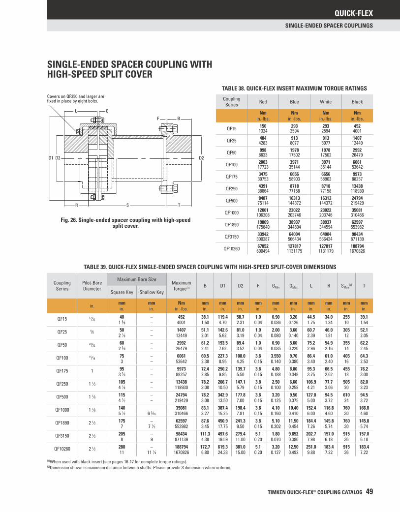
QUICK-FLEX
TIMKEN QUICK-FLEX® COUPLING CATALOG 49
SINGLE-ENDED SPACER COUPLINGS
SINGLE-ENDED SPACER COUPLING WITH HIGH-SPEED SPLIT COVER
Fig. 26. Single-ended spacer coupling with high-speed split cover.
TABLE 39. QUICK-FLEX SINGLE-ENDED SPACER COUPLING WITH HIGH-SPEED SPLIT-COVER DIMENSIONS
Coupling Series
Pilot-Bore Diameter
Maximum Bore SizeMaximum Torque(1) B D1 D2 F GMin GMax L R SMax
(2) TSquare Key Shallow Key
in. mmin.
mmin.
Nmin.-lbs.
mmin.
mmin.
mmin.
mmin.
mmin.
mmin.
mmin.
mmin.
mmin.
mmin.
QF15 17⁄3240 – 452 38.1 119.4 58.7 1.0 0.90 3.20 44.5 34.0 255 39.1
1 5⁄8 – 4001 1.50 4.70 2.31 0.04 0.036 0.126 1.75 1.34 10 1.54
QF25 5⁄8 50 – 1407 51.1 142.6 81.0 1.0 2.00 3.60 60.7 46.0 305 52.12 1⁄8 – 12449 2.01 5.62 3.19 0.04 0.080 0.140 2.39 1.81 12 2.05
QF50 23⁄3260 – 2992 61.2 193.5 89.4 1.0 0.90 5.60 75.2 54.9 355 62.2
2 3⁄8 – 26479 2.41 7.62 3.52 0.04 0.035 0.220 2.96 2.16 14 2.45
QF100 15⁄1675 – 6061 60.5 227.3 108.0 3.8 3.550 9.70 86.4 61.0 405 64.33 – 53642 2.38 8.95 4.25 0.15 0.140 0.380 3.40 2.40 16 2.53
QF175 1 95 – 9973 72.4 250.2 139.7 3.8 4.80 8.80 95.3 66.5 455 76.23 7⁄8 – 88257 2.85 9.85 5.50 0.15 0.188 0.348 3.75 2.62 18 3.00
QF250 1 1⁄2 105 – 13438 78.2 266.7 147.1 3.8 2.50 6.60 106.9 77.7 505 82.04 1⁄8 – 118930 3.08 10.50 5.79 0.15 0.100 0.258 4.21 3.06 20 3.23
QF500 1 7⁄8 115 – 24794 78.2 342.9 177.8 3.8 3.20 9.50 127.0 94.5 610 94.54 1⁄2 – 219429 3.08 13.50 7.00 0.15 0.125 0.375 5.00 3.72 24 3.72
QF1000 1 7⁄8 140 35081 83.1 387.4 198.4 3.8 4.10 10.40 152.4 116.8 760 166.85 1⁄2 6 3⁄16 310466 3.27 15.25 7.81 0.15 0.160 0.410 6.00 4.60 30 4.60
QF1890 2 1⁄2 175 – 62597 87.6 450.9 241.3 3.8 5.10 11.50 184.4 145.8 760 145.87 7 1⁄2 553982 3.45 17.75 9.50 0.15 0.202 0.454 7.26 5.74 30 5.74
QF3150 2 1⁄2 205 – 98434 111.3 497.6 279.4 5.1 1.80 9.652 202.7 157.0 915 157.08 9 871139 4.38 19.59 11.00 0.20 0.070 0.380 7.98 6.18 36 6.18
QF10260 2 1⁄2 280 – 188794 172.7 619.3 381.0 5.1 3.20 12.50 251.0 183.4 915 183.411 11 1⁄4 1670826 6.80 24.38 15.00 0.20 0.127 0.492 9.88 7.22 36 7.22
(1)When used with black insert (see pages 16-17 for complete torque ratings).(2)Dimension shown is maximum distance between shafts. Please provide S dimension when ordering.
L G
F B
D2
TSR
D2D1
Covers on QF250 and larger are fixed in place by eight bolts.
TABLE 38. QUICK-FLEX INSERT MAXIMUM TORQUE RATINGS
Coupling Series Red Blue White Black
Nmin.-lbs.
Nmin.-lbs.
Nmin.-lbs.
Nmin.-lbs.
150 293 293 452QF15 1324 2594 2594 4001484 913 913 1407QF25 4283 8077 8077 12449998 1978 1978 2992QF50 8833 17502 17502 26479
2003 3971 3971 6061QF100 17723 35144 35144 536423475 6656 6656 9973QF175 30753 58903 58903 882574391 8718 8718 13438QF250 38864 77158 77158 1189308487 16313 16313 24794QF500 75114 144372 144372 219429
12001 23022 23022 35081QF1000 106208 203746 203746 31046619869 38937 38937 62597QF1890 175840 344594 344594 55398233942 64004 64004 98434QF3150 300387 566434 566434 87113967852 127817 127817 188794QF10260 600494 1131179 1131179 1670826
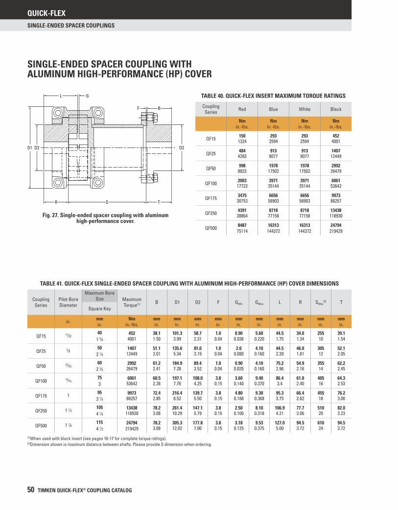
QUICK-FLEX
50 TIMKEN QUICK-FLEX® COUPLING CATALOG
SINGLE-ENDED SPACER COUPLINGS
SINGLE-ENDED SPACER COUPLING WITH ALUMINUM HIGH-PERFORMANCE (HP) COVER
Fig. 27. Single-ended spacer coupling with aluminum high-performance cover.
TABLE 41. QUICK-FLEX SINGLE-ENDED SPACER COUPLING WITH ALUMINUM HIGH-PERFORMANCE (HP) COVER DIMENSIONS
Coupling Series
Pilot-Bore Diameter
Maximum Bore Size Maximum
Torque(1) B D1 D2 F GMin GMax L R SMax(2) T
Square Key
in. mmin.
Nmin.-lbs.
mmin.
mmin.
mmin.
mmin.
mmin.
mmin.
mmin.
mmin.
mmin.
mmin.
QF15 17⁄3240 452 38.1 101.3 58.7 1.0 0.90 5.60 44.5 34.0 255 39.1
1 5⁄8 4001 1.50 3.99 2.31 0.04 0.036 0.220 1.75 1.34 10 1.54
QF25 5⁄8 50 1407 51.1 135.6 81.0 1.0 2.0 4.10 44.5 46.0 305 52.12 1⁄8 12449 2.01 5.34 3.19 0.04 0.080 0.160 2.39 1.81 12 2.05
QF50 23⁄3260 2992 61.2 184.9 89.4 1.0 0.90 4.10 75.2 54.9 355 62.2
2 3⁄8 26479 2.41 7.28 3.52 0.04 0.035 0.160 2.96 2.16 14 2.45
QF100 15⁄1675 6061 60.5 197.1 108.0 3.8 3.60 9.40 86.4 61.0 405 64.33 53642 2.38 7.76 4.25 0.15 0.140 0.370 3.4 2.40 16 2.53
QF175 1 95 9973 72.4 216.4 139.7 3.8 4.80 9.30 95.3 66.4 455 76.23 7⁄8 88257 2.85 8.52 5.50 0.15 0.188 0.368 3.75 2.62 18 3.00
QF250 1 1⁄2 105 13438 78.2 261.4 147.1 3.8 2.50 8.10 106.9 77.7 510 82.04 1⁄8 118930 3.08 10.29 5.79 0.15 0.100 0.318 4.21 3.06 20 3.23
QF500 1 7⁄8 115 24794 78.2 305.3 177.8 3.8 3.18 9.53 127.0 94.5 610 94.54 1⁄2 219429 3.08 12.02 7.00 0.15 0.125 0.375 5.00 3.72 24 3.72
(1)When used with black insert (see pages 16-17 for complete torque ratings).(2)Dimension shown is maximum distance between shafts. Please provide S dimension when ordering.
L G
D1 D2
R S T
D2
BF
TABLE 40. QUICK-FLEX INSERT MAXIMUM TORQUE RATINGS
Coupling Series Red Blue White Black
Nmin.-lbs.
Nmin.-lbs.
Nmin.-lbs.
Nmin.-lbs.
150 293 293 452QF15 1324 2594 2594 4001
484 913 913 1407QF25 4283 8077 8077 12449
998 1978 1978 2992QF50 8833 17502 17502 26479
2003 3971 3971 6061QF100 17723 35144 35144 53642
3475 6656 6656 9973QF175 30753 58903 58903 88257
4391 8718 8718 13438QF250 38864 77158 77158 118930
8487 16313 16313 24794QF500 75114 144372 144372 219429
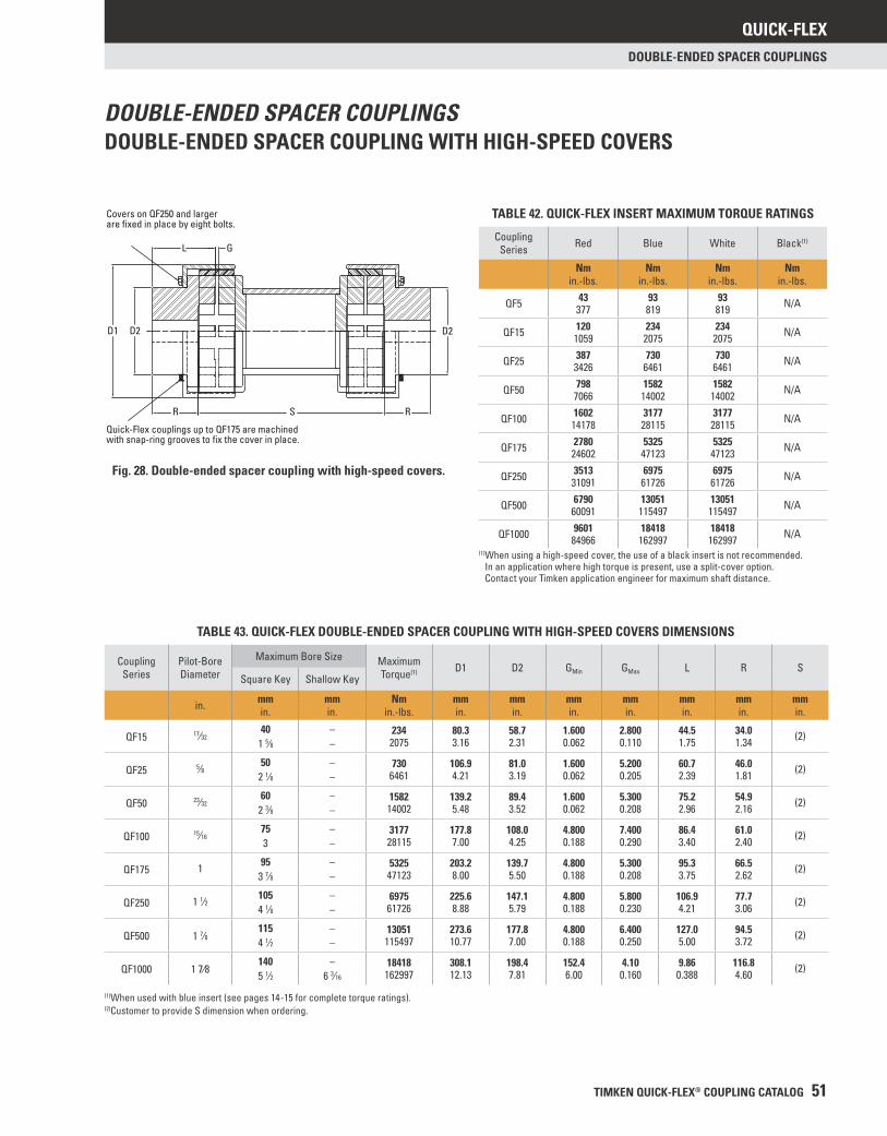
QUICK-FLEX
TIMKEN QUICK-FLEX® COUPLING CATALOG 51
DOUBLE-ENDED SPACER COUPLINGS
DOUBLE-ENDED SPACER COUPLINGSDOUBLE-ENDED SPACER COUPLING WITH HIGH-SPEED COVERS
Fig. 28. Double-ended spacer coupling with high-speed covers.
TABLE 43. QUICK-FLEX DOUBLE-ENDED SPACER COUPLING WITH HIGH-SPEED COVERS DIMENSIONS
Coupling Series
Pilot-Bore Diameter
Maximum Bore Size Maximum Torque(1) D1 D2 GMin GMax L R S
Square Key Shallow Key
in. mmin.
mmin.
Nmin.-lbs.
mmin.
mmin.
mmin.
mmin.
mmin.
mmin.
mmin.
QF15 17⁄3240 – 234 80.3 58.7 1.600 2.800 44.5 34.0
1 5⁄8 – 2075 3.16 2.31 0.062 0.110 1.75 1.34 (2)
QF25 5⁄8 50 – 730 106.9 81.0 1.600 5.200 60.7 46.02 1⁄8 – 6461 4.21 3.19 0.062 0.205 2.39 1.81 (2)
QF50 23⁄3260 – 1582 139.2 89.4 1.600 5.300 75.2 54.9
2 3⁄8 – 14002 5.48 3.52 0.062 0.208 2.96 2.16 (2)
QF100 15⁄1675 – 3177 177.8 108.0 4.800 7.400 86.4 61.03 – 28115 7.00 4.25 0.188 0.290 3.40 2.40 (2)
QF175 1 95 – 5325 203.2 139.7 4.800 5.300 95.3 66.53 7⁄8 – 47123 8.00 5.50 0.188 0.208 3.75 2.62 (2)
QF250 1 1⁄2 105 – 6975 225.6 147.1 4.800 5.800 106.9 77.74 1⁄8 – 61726 8.88 5.79 0.188 0.230 4.21 3.06 (2)
QF500 1 7⁄8115 – 13051 273.6 177.8 4.800 6.400 127.0 94.54 1⁄2 – 115497 10.77 7.00 0.188 0.250 5.00 3.72 (2)
QF1000 1 7⁄8140 – 18418 308.1 198.4 152.4 4.10 9.86 116.85 1⁄2 6 3⁄16 162997 12.13 7.81 6.00 0.160 0.388 4.60 (2)
(1)When used with blue insert (see pages 14-15 for complete torque ratings).(2)Customer to provide S dimension when ordering.
TABLE 42. QUICK-FLEX INSERT MAXIMUM TORQUE RATINGS
Coupling Series Red Blue White Black(1)
Nmin.-lbs.
Nmin.-lbs.
Nmin.-lbs.
Nmin.-lbs.
43 93 93 N/AQF5 377 819 819120 234 234 N/AQF15 1059 2075 2075387 730 730 N/AQF25 3426 6461 6461798 1582 1582 N/AQF50 7066 14002 14002
1602 3177 3177 N/AQF100 14178 28115 281152780 5325 5325 N/AQF175 24602 47123 471233513 6975 6975 N/AQF250 31091 61726 617266790 13051 13051 N/AQF500 60091 115497 1154979601 18418 18418 N/AQF1000 84966 162997 162997
(1) When using a high-speed cover, the use of a black insert is not recommended. In an application where high torque is present, use a split-cover option. Contact your Timken application engineer for maximum shaft distance.
Covers on QF250 and larger are fixed in place by eight bolts.
Quick-Flex couplings up to QF175 are machined with snap-ring grooves to fix the cover in place.
L G
D1 D2
R S R
D2
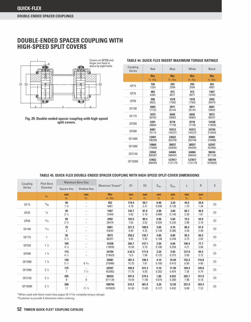
QUICK-FLEX
52 TIMKEN QUICK-FLEX® COUPLING CATALOG
DOUBLE-ENDED SPACER COUPLINGS
DOUBLE-ENDED SPACER COUPLING WITH HIGH-SPEED SPLIT COVERS
Fig. 29. Double-ended spacer coupling with high-speed split covers.
TABLE 45. QUICK-FLEX DOUBLE-ENDED SPACER COUPLING WITH HIGH-SPEED SPLIT-COVER DIMENSIONS
Coupling Series
Pilot-Bore Diameter
Maximum Bore SizeMaximum Torque(1) D1 D2 GMin GMax L R S
Square Key Shallow Key
in. mmin.
mmin.
Nmin.-lbs.
mmin.
mmin.
mmin.
mmin.
mmin.
mmin.
QF15 17⁄3240 – 452 119.4 58.7 0.90 3.20 44.5 34.0
1 5⁄8 – 4001 4.70 2.31 0.036 0.126 1.75 1.34 (2)
QF25 5⁄8 50 – 1407 142.7 81.0 2.00 3.60 60.7 46.02 1⁄8 – 12449 5.62 3.19 0.080 0.140 2.39 1.81 (2)
QF50 23⁄3260 – 2992 193.5 89.4 0.90 5.60 75.2 54.9
2 3⁄8 – 26479 7.62 3.52 0.035 0.220 2.96 2.16 (2)
QF100 15⁄1675 – 6061 227.3 108.0 3.60 9.70 86.4 61.03 – 53642 8.95 4.25 0.140 0.380 3.40 2.40 (2)
QF175 1 95 – 9973 250.2 139.7 4.80 8.80 95.3 66.53 7⁄8 – 88257 9.85 5.50 0.188 0.348 3.75 2.62 (2)
QF250 1 1⁄2 105 – 13438 266.7 147.1 2.50 6.60 106.9 77.74 1⁄8 – 118930 10.50 5.79 0.100 0.258 4.21 3.06 (2)
QF500 1 7⁄8 115 – 24794 3.42.9 177.8 3.20 9.50 127.0 94.54 1⁄2 – 219429 13.5 7.00 0.125 0.375 5.00 3.72 (2)
QF1000 1 7⁄8 140 35081 387.4 198.4 4.10 10.40 152.4 116.85 1⁄2 6 3⁄16 310466 15.25 7.81 0.160 0.410 6.00 4.60 (2)
QF1890 2 1⁄2 175 – 62597 450.9 241.3 5.10 11.50 184.4 145.87 7 1⁄2 553982 17.75 9.50 0.202 0.454 7.26 5.74 (2)
QF3150 2 1⁄2 205 – 98434 497.6 279.4 1.80 9.652 202.7 157.08 9 871139 19.59 11.00 0.070 0.380 7.98 6.18 (2)
QF10260 2 1⁄2 280 – 188794 619.3 381.0 3.20 12.50 251.0 183.411 11 1⁄4 1670826 24.38 15.00 0.127 0.492 9.88 7.22 (2)
(1)When used with black insert (see pages 16-17 for complete torque ratings).(2)Customer to provide S dimension when ordering.
LG
D1 D2 D2
R RS
Covers on QF250 andlarger are fixed in place by eight bolts.
TABLE 44. QUICK-FLEX INSERT MAXIMUM TORQUE RATINGS
Coupling Series Red Blue White Black
Nmin.-lbs.
Nmin.-lbs.
Nmin.-lbs.
Nmin.-lbs.
150 293 293 452QF15 1324 2594 2594 4001484 913 913 1407QF25 4283 8077 8077 12449998 1978 1978 2992QF50 8833 17502 17502 26479
2003 3971 3971 6061QF100 17723 35144 35144 536423475 6656 6656 9973QF175 30753 58903 58903 882574391 8718 8718 13438QF250 38864 77158 77158 1189308487 16313 16313 24794QF500 75114 144372 144372 219429
12001 23022 23022 35081QF1000 106208 203746 203746 31046619869 38937 38937 62597QF1890 175840 344594 344594 55398233942 64004 64004 98434QF3150 300387 566434 566434 87113967852 127817 127817 188794QF10260 600494 1131179 1131179 1670826
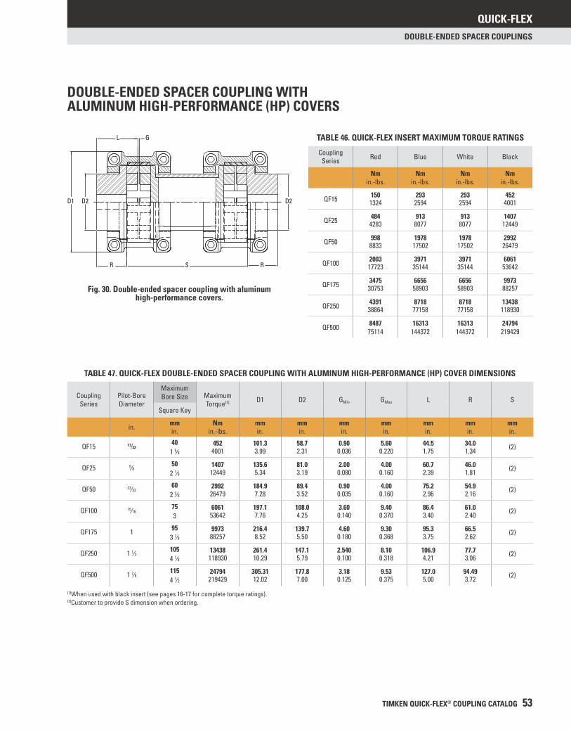
QUICK-FLEX
TIMKEN QUICK-FLEX® COUPLING CATALOG 53
DOUBLE-ENDED SPACER COUPLINGS
DOUBLE-ENDED SPACER COUPLING WITH ALUMINUM HIGH-PERFORMANCE (HP) COVERS
Fig. 30. Double-ended spacer coupling with aluminum high-performance covers.
TABLE 47. QUICK-FLEX DOUBLE-ENDED SPACER COUPLING WITH ALUMINUM HIGH-PERFORMANCE (HP) COVER DIMENSIONS
Coupling Series
Pilot-Bore Diameter
Maximum Bore Size Maximum
Torque(1) D1 D2 GMin GMax L R SSquare Key
in. mmin.
Nmin.-lbs.
mmin.
mmin.
mmin.
mmin.
mmin.
mmin.
mmin.
QF15 17⁄3240 452 101.3 58.7 0.90 5.60 44.5 34.0
1 5⁄8 4001 3.99 2.31 0.036 0.220 1.75 1.34 (2)
QF25 5⁄8 50 1407 135.6 81.0 2.00 4.00 60.7 46.02 1⁄8 12449 5.34 3.19 0.080 0.160 2.39 1.81 (2)
QF50 23⁄3260 2992 184.9 89.4 0.90 4.00 75.2 54.9
2 3⁄8 26479 7.28 3.52 0.035 0.160 2.96 2.16 (2)
QF100 15⁄1675 6061 197.1 108.0 3.60 9.40 86.4 61.03 53642 7.76 4.25 0.140 0.370 3.40 2.40 (2)
QF175 1 95 9973 216.4 139.7 4.60 9.30 95.3 66.53 7⁄8 88257 8.52 5.50 0.180 0.368 3.75 2.62 (2)
QF250 1 1⁄2 105 13438 261.4 147.1 2.540 8.10 106.9 77.74 1⁄8 118930 10.29 5.79 0.100 0.318 4.21 3.06 (2)
QF500 1 7⁄8 115 24794 305.31 177.8 3.18 9.53 127.0 94.494 1⁄2 219429 12.02 7.00 0.125 0.375 5.00 3.72 (2)
(1)When used with black insert (see pages 16-17 for complete torque ratings).(2)Customer to provide S dimension when ordering.
TABLE 46. QUICK-FLEX INSERT MAXIMUM TORQUE RATINGS
Coupling Series Red Blue White Black
Nmin.-lbs.
Nmin.-lbs.
Nmin.-lbs.
Nmin.-lbs.
150 293 293 452QF15 1324 2594 2594 4001
484 913 913 1407QF25 4283 8077 8077 12449
998 1978 1978 2992QF50 8833 17502 17502 26479
2003 3971 3971 6061QF100 17723 35144 35144 53642
3475 6656 6656 9973QF175 30753 58903 58903 88257
4391 8718 8718 13438QF250 38864 77158 77158 118930
8487 16313 16313 24794QF500 75114 144372 144372 219429
D1 D2
R S R
D2
GL

QUICK-FLEX
54 TIMKEN QUICK-FLEX® COUPLING CATALOG
DOUBLE-ENDED SPACER COUPLINGS
DOUBLE-ENDED SPACER FLANGE COUPLING WITH HIGH-SPEED SPLIT COVERS
Fig. 31. Double-ended spacer fl ange coupling with high-speed split covers.
TABLE 48. QUICK-FLEX DOUBLE-ENDED SPACER FLANGE COUPLING WITH HIGH-SPEED SPLIT-COVER DIMENSIONS
Coupling Series
G52 Gear Coupling
Maximum Torque(1) B.C. D1 D2 GMin GMax L S SMin
Nmin.-lbs.
mmin.
mmin.
mmin.
mmin.
mmin.
mmin.
mmin.
mmin.
QF25 1010G521407 95.3 147.8 115.9 2.03 3.56 59.2 198.112449 3.75 5.62 4.56 0.080 0.140 2.33 (2) 7.80
QF50 1015G522992 122.2 193.5 152.4 0.89 5.59 78.2 263.726479 4.81 7.62 6.00 0.035 0.220 3.08 (2) 10.38
QF100 1020G526061 149.2 227.3 177.8 3.56 9.65 100.1 345.453642 5.88 8.95 7.00 0.140 0.380 3.94 (2) 13.60
QF175 1025G529973 181.0 250.2 212.7 4.78 8.84 112.5 374.788257 7.13 9.85 8.38 0.188 0.348 4.43 (2) 14.75
QF250 1030G5213438 206.4 266.7 239.7 2.54 6.55 154.2 451.4118930 8.13 10.50 9.44 0.100 0.258 6.07 (2) 17.77
QF500 1035G5224794 241.3 342.9 279.4 3.18 9.53 188.2 563.9219429 9.50 13.50 11.00 0.125 0.375 7.41 (2) 22.20
QF500 1040G5224794 279.4 312.2 317.5 3.18 9.53 188.2 563.9219429 11.00 12.29 12.50 0.125 0.375 7.41 (2) 22.20
QF1000 1045G5235081 304.8 387.4 346.1 4.06 10.41 192.0 580.1310466 12.00 15.25 13.63 0.160 0.410 7.56 (2) 22.84
QF1890 1050G5262597 342.9 450.9 389.0 5.13 11.53 219.7 673.1553982 13.50 17.75 15.31 0.202 0.454 8.65 (2) 26.50
QF1890 1055G5262597 368.3 450.9 425.4 5.13 11.53 219.7 673.1553982 14.50 17.75 16.75 0.202 0.454 8.65 (2) 26.50
QF3150 1060G5298434 400.1 497.6 457.2 1.78 11.56 209.0 644.7871138 15.75 19.59 18.00 0.070 0.455 8.23 (2) 25.38
QF10260 1070G52188794 469.9 619.3 527.1 3.23 12.50 258.6 850.9
1670826 18.50 24.38 20.75 0.127 0.492 10.18 (2) 33.50
QF10260 1080G52188794 527.1 619.3 603.3 3.23 12.50 266.5 866.1
1670826 20.75 24.38 23.75 0.127 0.492 10.49 (2) 34.10
QF10260 1090G52188794 590.6 619.3 660.4 3.23 12.50 276.6 886.0
1670826 23.25 24.38 26.00 0.127 0.492 10.89 (2) 34.88
(1)When used with black insert (see pages 16-17 for complete torque ratings).(2)Customer to provide S dimension when ordering.
D1
S
GL
Bolt no. - diameter
Covers on QF250 and larger are fixed in place by eight bolts.
B.C. D2
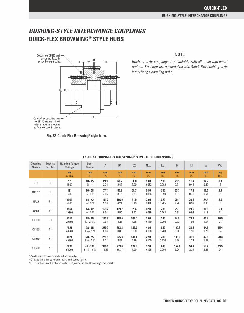
QUICK-FLEX
TIMKEN QUICK-FLEX® COUPLING CATALOG 55
BUSHING-STYLE INTERCHANGE COUPLINGS
NOTE
Bushing-style couplings are available with all cover and insert options. Bushings are not supplied with Quick-Flex bushing-style interchange coupling hubs.
BUSHING-STYLE INTERCHANGE COUPLINGSQUICK-FLEX BROWNING® STYLE HUBS
TABLE 49. QUICK-FLEX BROWNING® STYLE HUB DIMENSIONS
Coupling Series
Bushing Part No.
Bushing Torque Ratings
Bore Range A D1 D2 GMin GMax H L1 W Wt.
Nmin.-lbs.
mmin.
mmin.
mmin.
mmin.
mmin.
mmin.
mmin.
mmin.
mmin.
kglbs.
QF5 G 203 10 - 25 69.9 63.2 50.8 1.60 2.30 23.1 11.4 12.7 0.91800 1⁄2 - 1 2.75 2.49 2.00 0.062 0.092 0.91 0.45 0.50 2
QF15(1) H 421 10 - 38 77.7 80.3 58.7 0.90 2.50 33.3 17.8 15.5 2.33730 3⁄8 - 1 1⁄2 3.06 3.16 2.31 0.036 0.099 1.31 0.70 0.61 5
QF25 P1 1069 14 - 42 141.7 106.9 81.0 2.00 5.20 70.1 23.4 24.4 3.69460 1⁄2 - 1 3⁄4 5.58 4.21 3.19 0.08 0.205 2.76 0.92 0.96 8
QF50 P1 1164 14 - 42 153.2 139.7 89.4 0.90 5.30 75.7 23.6 30.0 5.910300 1⁄2 - 1 3⁄4 6.03 5.50 3.52 0.035 0.208 2.98 0.93 1.18 13
QF100 Q1 2316 18 - 65 193.8 108.0 108.0 3.60 7.40 94.5 26.4 41.7 10.920500 3⁄4 - 2 11⁄16 7.63 4.25 4.25 0.140 0.290 3.72 1.04 1.64 24
QF175 R1 4621 28 - 95 220.0 203.2 139.7 4.80 5.30 100.6 33.8 44.5 15.440900 1 1⁄8 - 3 3⁄4 8.66 8.00 5.50 0.188 0.208 3.96 1.33 1.75 34
QF250 R1 4621 28 - 95 221.5 225.3 147.1 2.50 5.80 108.2 31.0 47.8 20.440900 1 1⁄8 - 3 3⁄4 8.72 8.87 5.79 0.100 0.230 4.26 1.22 1.88 45
QF500 S1 5876 42 - 100 309.4 273.6 177.8 3.20 6.40 152.4 58.7 57.2 43.552000 1 11⁄16 - 4 1⁄4 12.18 10.77 7.00 0.125 0.250 6.00 2.31 2.25 96
(1)Available with low-speed split cover only.NOTE: Bushing limits torque rating and speed rating.NOTE: Timken is not affi liated with EPT®, owner of the Browning® trademark.
Fig. 32. Quick-Flex Browning® style hubs.
W
Covers on QF250 and larger are fixed in
place by eight bolts. L1 GH
D1 D2
AQuick-Flex couplings up to QF175 are machined with snap-ring grooves to fix the cover in place.
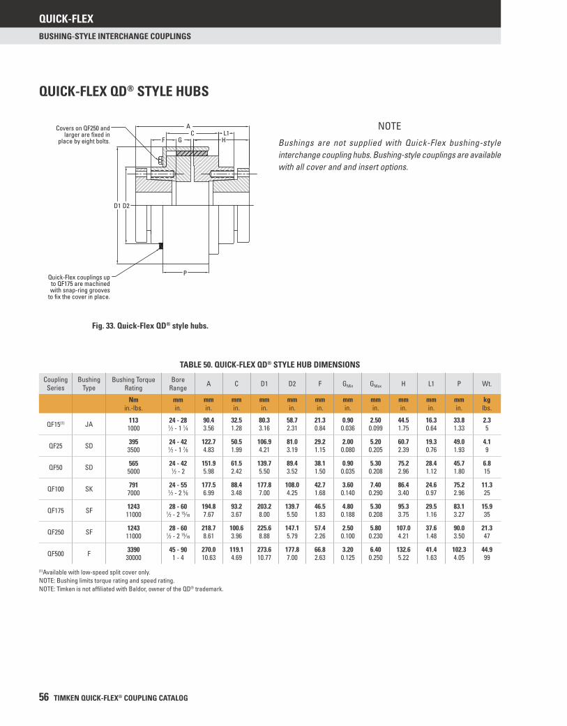
QUICK-FLEX
56 TIMKEN QUICK-FLEX® COUPLING CATALOG
BUSHING-STYLE INTERCHANGE COUPLINGS
QUICK-FLEX QD® STYLE HUBS
Fig. 33. Quick-Flex QD® style hubs.
NOTE
Bushings are not supplied with Quick-Flex bushing-style interchange coupling hubs. Bushing-style couplings are available with all cover and and insert options.
TABLE 50. QUICK-FLEX QD® STYLE HUB DIMENSIONS
Coupling Series
Bushing Type
Bushing Torque Rating
Bore Range A C D1 D2 F GMin GMax H L1 P Wt.
Nmin.-lbs.
mmin.
mmin.
mmin.
mmin.
mmin.
mmin.
mmin.
mmin.
mmin.
mmin.
mmin.
kglbs.
QF15(1) JA 113 24 - 28 90.4 32.5 80.3 58.7 21.3 0.90 2.50 44.5 16.3 33.8 2.31000 1⁄2 - 1 1⁄4 3.56 1.28 3.16 2.31 0.84 0.036 0.099 1.75 0.64 1.33 5
QF25 SD 395 24 - 42 122.7 50.5 106.9 81.0 29.2 2.00 5.20 60.7 19.3 49.0 4.13500 1⁄2 - 1 7⁄8 4.83 1.99 4.21 3.19 1.15 0.080 0.205 2.39 0.76 1.93 9
QF50 SD 565 24 - 42 151.9 61.5 139.7 89.4 38.1 0.90 5.30 75.2 28.4 45.7 6.85000 1⁄2 - 2 5.98 2.42 5.50 3.52 1.50 0.035 0.208 2.96 1.12 1.80 15
QF100 SK 791 24 - 55 177.5 88.4 177.8 108.0 42.7 3.60 7.40 86.4 24.6 75.2 11.37000 1⁄2 - 2 5⁄8 6.99 3.48 7.00 4.25 1.68 0.140 0.290 3.40 0.97 2.96 25
QF175 SF 1243 28 - 60 194.8 93.2 203.2 139.7 46.5 4.80 5.30 95.3 29.5 83.1 15.911000 1⁄2 - 2 15⁄16 7.67 3.67 8.00 5.50 1.83 0.188 0.208 3.75 1.16 3.27 35
QF250 SF 1243 28 - 60 218.7 100.6 225.6 147.1 57.4 2.50 5.80 107.0 37.6 90.0 21.311000 1⁄2 - 2 15⁄16 8.61 3.96 8.88 5.79 2.26 0.100 0.230 4.21 1.48 3.50 47
QF500 F 3390 45 - 90 270.0 119.1 273.6 177.8 66.8 3.20 6.40 132.6 41.4 102.3 44.930000 1 - 4 10.63 4.69 10.77 7.00 2.63 0.125 0.250 5.22 1.63 4.05 99
(1)Available with low-speed split cover only.NOTE: Bushing limits torque rating and speed rating.NOTE: Timken is not affi liated with Baldor, owner of the QD® trademark.
Covers on QF250 andlarger are fixed in
place by eight bolts.
Quick-Flex couplings upto QF175 are machinedwith snap-ring grooves
to fix the cover in place.
A
FC
H
D1
P
D2
GL1
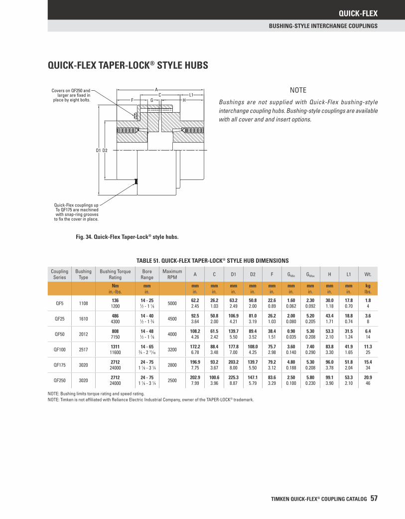
QUICK-FLEX
TIMKEN QUICK-FLEX® COUPLING CATALOG 57
BUSHING-STYLE INTERCHANGE COUPLINGS
QUICK-FLEX TAPER-LOCK® STYLE HUBS
Fig. 34. Quick-Flex Taper-Lock® style hubs.
NOTE
Bushings are not supplied with Quick-Flex bushing-style interchange coupling hubs. Bushing-style couplings are available with all cover and and insert options.
TABLE 51. QUICK-FLEX TAPER-LOCK® STYLE HUB DIMENSIONS
Coupling Series
Bushing Type
Bushing Torque Rating
Bore Range
MaximumRPM A C D1 D2 F GMin GMax H L1 Wt.
Nmin.-lbs.
mmin.
mmin.
mmin.
mmin.
mmin.
mmin.
mmin.
mmin.
mmin.
mmin.
kglbs.
QF5 1108 136 14 - 25 5000 62.2 26.2 63.2 50.8 22.6 1.60 2.30 30.0 17.8 1.81200 1⁄2 - 1 1⁄8 2.45 1.03 2.49 2.00 0.89 0.062 0.092 1.18 0.70 4
QF25 1610 486 14 - 40 4500 92.5 50.8 106.9 81.0 26.2 2.00 5.20 43.4 18.8 3.64300 1⁄2 - 1 3⁄4 3.64 2.00 4.21 3.19 1.03 0.080 0.205 1.71 0.74 8
QF50 2012 808 14 - 48 4000 108.2 61.5 139.7 89.4 38.4 0.90 5.30 53.3 31.5 6.47150 1⁄2 - 1 7⁄8 4.26 2.42 5.50 3.52 1.51 0.035 0.208 2.10 1.24 14
QF100 2517 1311 14 - 65 3200 172.2 88.4 177.8 108.0 75.7 3.60 7.40 83.8 41.9 11.311600 3⁄4 - 2 11⁄16 6.78 3.48 7.00 4.25 2.98 0.140 0.290 3.30 1.65 25
QF175 3020 2712 24 - 75 2800 196.9 93.2 203.2 139.7 79.2 4.80 5.30 96.0 51.8 15.424000 1 1⁄8 - 3 1⁄4 7.75 3.67 8.00 5.50 3.12 0.188 0.208 3.78 2.04 34
QF250 3020 2712 24 - 75 2500 202.9 100.6 225.3 147.1 83.6 2.50 5.80 99.1 53.3 20.924000 1 1⁄8 - 3 1⁄4 7.99 3.96 8.87 5.79 3.29 0.100 0.230 3.90 2.10 46
NOTE: Bushing limits torque rating and speed rating.NOTE: Timken is not affi liated with Reliance Electric Industrial Company, owner of the TAPER-LOCK® trademark.
Covers on QF250 andlarger are fixed in
place by eight bolts.
Quick-Flex couplings upTo QF175 are machinedwith snap-ring grooves
to fix the cover in place.
D1 D2
A
F GC L1
H
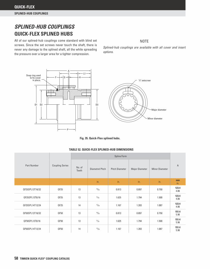
QUICK-FLEX
58 TIMKEN QUICK-FLEX® COUPLING CATALOG
SPLINED-HUB COUPLINGS
TABLE 52. QUICK-FLEX SPLINED-HUB DIMENSIONS
Part Number Coupling Series
Spline Form
ANo. of Teeth Diametrel Pitch Pitch Diameter Major Diameter Minor Diameter
in. in. in. in. mmin.
QF25SPL13T16/32 QF25 13 16⁄32 0.813 0.897 0.750 123.44.86
QF25SPL13T8/16 QF25 13 8⁄16 1.625 1.794 1.500 123.44.86
QF25SPL14T12/24 QF25 14 12⁄24 1.167 1.283 1.087 123.44.86
QF50SPL13T16/32 QF50 13 16⁄32 0.813 0.897 0.750 151.45.96
QF50SPL13T8/16 QF50 13 8⁄16 1.625 1.794 1.500 151.45.96
QF50SPL14T12/24 QF50 14 12⁄24 1.167 1.283 1.087 151.45.96
1⁄2" setscrew
Major diameter
Minor diameter
AC
HGFL1
D1 D2
P
D3
Snap ring usedto fix cover
in place.
NOTE
Splined-hub couplings are available with all cover and insert options.
SPLINED-HUB COUPLINGSQUICK-FLEX SPLINED HUBSAll of our splined-hub couplings come standard with blind set screws. Since the set screws never touch the shaft, there is never any damage to the splined shaft, all the while spreading the pressure over a larger area for a tighter compression.
Fig. 35. Quick-Flex splined hubs.
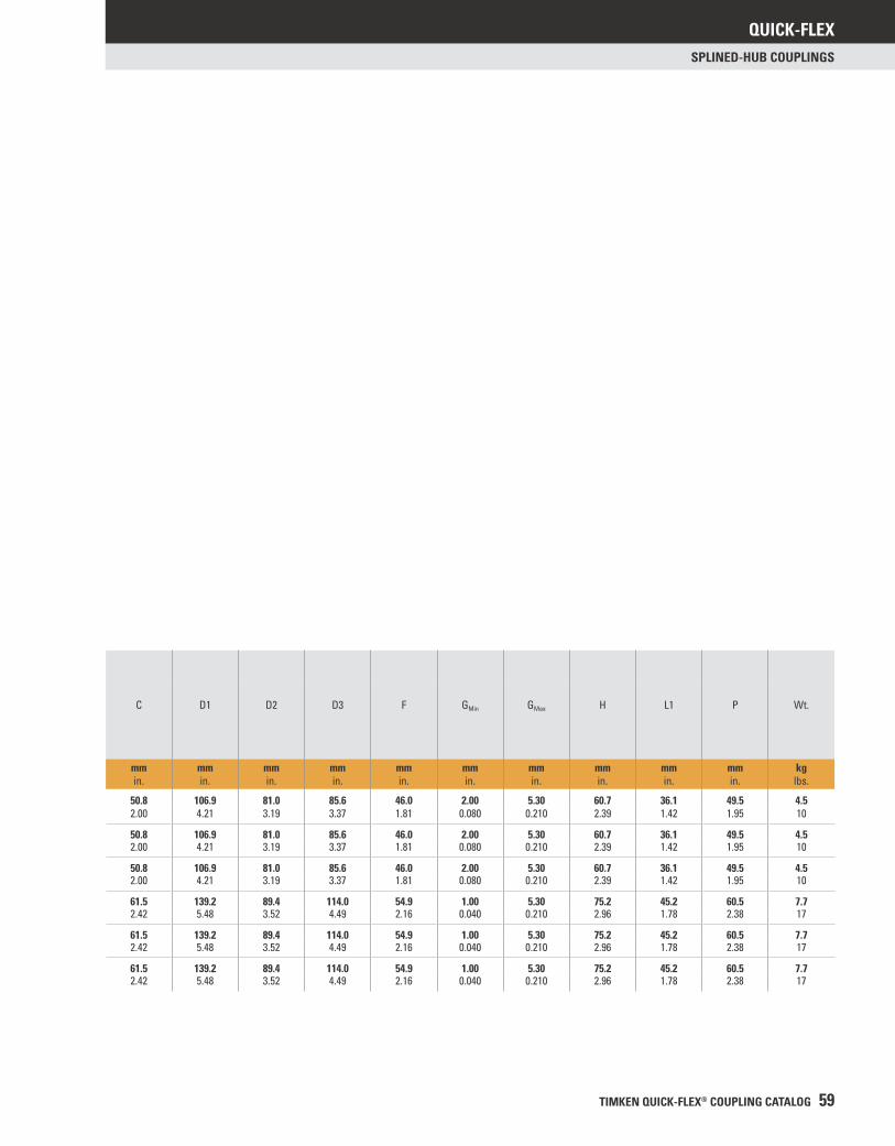
QUICK-FLEX
TIMKEN QUICK-FLEX® COUPLING CATALOG 59
SPLINED-HUB COUPLINGS
C D1 D2 D3 F GMin GMax H L1 P Wt.
mmin.
mmin.
mmin.
mmin.
mmin.
mmin.
mmin.
mmin.
mmin.
mmin.
kglbs.
50.8 106.9 81.0 85.6 46.0 2.00 5.30 60.7 36.1 49.5 4.52.00 4.21 3.19 3.37 1.81 0.080 0.210 2.39 1.42 1.95 10
50.8 106.9 81.0 85.6 46.0 2.00 5.30 60.7 36.1 49.5 4.52.00 4.21 3.19 3.37 1.81 0.080 0.210 2.39 1.42 1.95 10
50.8 106.9 81.0 85.6 46.0 2.00 5.30 60.7 36.1 49.5 4.52.00 4.21 3.19 3.37 1.81 0.080 0.210 2.39 1.42 1.95 10
61.5 139.2 89.4 114.0 54.9 1.00 5.30 75.2 45.2 60.5 7.72.42 5.48 3.52 4.49 2.16 0.040 0.210 2.96 1.78 2.38 17
61.5 139.2 89.4 114.0 54.9 1.00 5.30 75.2 45.2 60.5 7.72.42 5.48 3.52 4.49 2.16 0.040 0.210 2.96 1.78 2.38 17
61.5 139.2 89.4 114.0 54.9 1.00 5.30 75.2 45.2 60.5 7.72.42 5.48 3.52 4.49 2.16 0.040 0.210 2.96 1.78 2.38 17
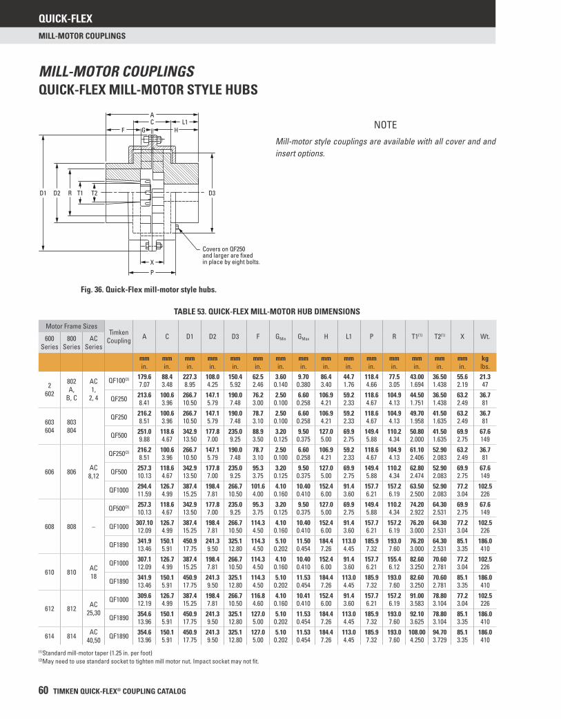
QUICK-FLEX
60 TIMKEN QUICK-FLEX® COUPLING CATALOG
MILL-MOTOR COUPLINGS
MILL-MOTOR COUPLINGSQUICK-FLEX MILL-MOTOR STYLE HUBS
Fig. 36. Quick-Flex mill-motor style hubs.
NOTE
Mill-motor style couplings are available with all cover and and insert options.
TABLE 53. QUICK-FLEX MILL-MOTOR HUB DIMENSIONS
Motor Frame SizesTimken
Coupling A C D1 D2 D3 F GMin GMax H L1 P R T1(1) T2(1) X Wt.600 Series
800 Series
AC Series
mmin.
mmin.
mmin.
mmin.
mmin.
mmin.
mmin.
mmin.
mmin.
mmin.
mmin.
mmin.
mmin.
mmin.
mmin.
kglbs.
2602
802 A,
B, C
AC 1,
2, 4
QF100(2) 179.6 88.4 227.3 108.0 150.4 62.5 3.60 9.70 86.4 44.7 118.4 77.5 43.00 36.50 55.6 21.37.07 3.48 8.95 4.25 5.92 2.46 0.140 0.380 3.40 1.76 4.66 3.05 1.694 1.438 2.19 47
QF250 213.6 100.6 266.7 147.1 190.0 76.2 2.50 6.60 106.9 59.2 118.6 104.9 44.50 36.50 63.2 36.78.41 3.96 10.50 5.79 7.48 3.00 0.100 0.258 4.21 2.33 4.67 4.13 1.751 1.438 2.49 81
603604
803804
QF250 216.2 100.6 266.7 147.1 190.0 78.7 2.50 6.60 106.9 59.2 118.6 104.9 49.70 41.50 63.2 36.78.51 3.96 10.50 5.79 7.48 3.10 0.100 0.258 4.21 2.33 4.67 4.13 1.958 1.635 2.49 81
QF500 251.0 118.6 342.9 177.8 235.0 88.9 3.20 9.50 127.0 69.9 149.4 110.2 50.80 41.50 69.9 67.69.88 4.67 13.50 7.00 9.25 3.50 0.125 0.375 5.00 2.75 5.88 4.34 2.000 1.635 2.75 149
606 806 AC 8,12
QF250(2) 216.2 100.6 266.7 147.1 190.0 78.7 2.50 6.60 106.9 59.2 118.6 104.9 61.10 52.90 63.2 36.78.51 3.96 10.50 5.79 7.48 3.10 0.100 0.258 4.21 2.33 4.67 4.13 2.406 2.083 2.49 81
QF500 257.3 118.6 342.9 177.8 235.0 95.3 3.20 9.50 127.0 69.9 149.4 110.2 62.80 52.90 69.9 67.610.13 4.67 13.50 7.00 9.25 3.75 0.125 0.375 5.00 2.75 5.88 4.34 2.474 2.083 2.75 149
QF1000 294.4 126.7 387.4 198.4 266.7 101.6 4.10 10.40 152.4 91.4 157.7 157.2 63.50 52.90 77.2 102.511.59 4.99 15.25 7.81 10.50 4.00 0.160 0.410 6.00 3.60 6.21 6.19 2.500 2.083 3.04 226
608 808 –
QF500(2) 257.3 118.6 342.9 177.8 235.0 95.3 3.20 9.50 127.0 69.9 149.4 110.2 74.20 64.30 69.9 67.610.13 4.67 13.50 7.00 9.25 3.75 0.125 0.375 5.00 2.75 5.88 4.34 2.922 2.531 2.75 149
QF1000 307.10 126.7 387.4 198.4 266.7 114.3 4.10 10.40 152.4 91.4 157.7 157.2 76.20 64.30 77.2 102.512.09 4.99 15.25 7.81 10.50 4.50 0.160 0.410 6.00 3.60 6.21 6.19 3.000 2.531 3.04 226
QF1890 341.9 150.1 450.9 241.3 325.1 114.3 5.10 11.50 184.4 113.0 185.9 193.0 76.20 64.30 85.1 186.013.46 5.91 17.75 9.50 12.80 4.50 0.202 0.454 7.26 4.45 7.32 7.60 3.000 2.531 3.35 410
610 810 AC 18
QF1000 307.1 126.7 387.4 198.4 266.7 114.3 4.10 10.40 152.4 91.4 157.7 155.4 82.60 70.60 77.2 102.512.09 4.99 15.25 7.81 10.50 4.50 0.160 0.410 6.00 3.60 6.21 6.12 3.250 2.781 3.04 226
QF1890 341.9 150.1 450.9 241.3 325.1 114.3 5.10 11.53 184.4 113.0 185.9 193.0 82.60 70.60 85.1 186.013.46 5.91 17.75 9.50 12.80 4.50 0.202 0.454 7.26 4.45 7.32 7.60 3.250 2.781 3.35 410
612 812 AC 25,30
QF1000 309.6 126.7 387.4 198.4 266.7 116.8 4.10 10.41 152.4 91.4 157.7 157.2 91.00 78.80 77.2 102.512.19 4.99 15.25 7.81 10.50 4.60 0.160 0.410 6.00 3.60 6.21 6.19 3.583 3.104 3.04 226
QF1890 354.6 150.1 450.9 241.3 325.1 127.0 5.10 11.53 184.4 113.0 185.9 193.0 92.10 78.80 85.1 186.013.96 5.91 17.75 9.50 12.80 5.00 0.202 0.454 7.26 4.45 7.32 7.60 3.625 3.104 3.35 410
614 814 AC 40,50 QF1890 354.6 150.1 450.9 241.3 325.1 127.0 5.10 11.53 184.4 113.0 185.9 193.0 108.00 94.70 85.1 186.0
13.96 5.91 17.75 9.50 12.80 5.00 0.202 0.454 7.26 4.45 7.32 7.60 4.250 3.729 3.35 410
(1)Standard mill-motor taper (1.25 in. per foot)(2)May need to use standard socket to tighten mill motor nut. Impact socket may not fi t.
D1 D2
Covers on QF250and larger are fixedin place by eight bolts.
R T1 T2 D3
X
P
AC
F G HL1

SPHERICAL ROLLER BEARING METRIC ACCESSORIES
184 TIMKEN SPHERICAL ROLLER BEARING CATALOG
NOTES

BA
GMin GMin
B A
A A
BB
Note gap. GMax GMax
Note gap.
BA B A
TIMKEN
® COU
PLING
CATALO
G
TIMKEN QUICK-FLEX® COUPLING CATALOG
www.timken.com
The Timken team applies their know-how to improve the reliability and performance of machinery in diverse markets worldwide. The company designs, makes and markets high-performance steel as well as mechanical components, including bearings, gears, chain and related mechanical power transmission products and services.
15M
2-1
3: 2
9 O
rder
No.
105
09 |
Tim
ken®
is a
regi
ster
ed tr
adem
ark
of T
he T
imke
n Co
mpa
ny.
| ©
201
3 Th
e Ti
mke
n Co
mpa
ny |
Prin
ted
in U
.S.A
.
Price: USD $75