tinyos overview
DESCRIPTION
TinyOS Overview. Source : System Architecture Directions or Networked Sensors - Jason Hill, Robert Szewcyk, Alec Woo, Seth Hollar, David Culler, Kristofer Pister The Mica Sensing Platform – Alec Woo, Jan. 14 2002, NEST Retreat Mica Node Architecture – Jason Hill, Jan. 14 2002, WEBS Retreat - PowerPoint PPT PresentationTRANSCRIPT
Source :
System Architecture Directions or Networked Sensors - Jason Hill, Robert Szewcyk, Alec Woo, Seth Hollar, David Culler, Kristofer Pister
The Mica Sensing Platform – Alec Woo, Jan. 14 2002, NEST Retreat
Mica Node Architecture – Jason Hill, Jan. 14 2002, WEBS Retreat
All Sources could be located at: http://webs.berkeley.edu/tos/media.html
Presented by Mark Miyashita
06-18-2002
TinyOS Overview
TinyOS Introduction
Computing in a Cubic millimeter
• Advances in low power wireless communication technology and micro-electromechanical sensors (MEMS) transducers make this possible
• Continued progress in inexpensive MEMS based sensors and communication technology accelerate research in the embedded network sensor for information processing
TinyOS IntroductionComputing in a Cubic millimeter
• Networked sensor is emerging area of interest as a result of advancement in RF communication technology and MEMS
• TinyOS (an event based operating environment) explores the software support for this emerging area of networked sensor
• It combines sensing, communication, and computation into single architecture Complete systems on a chip (micro controller + memory + sensors + interfaces etc)
Network Sensor Characteristics
• Use commercial components to build sensors
• Small Physical size (as small as square inch)
• Low Power consumption.
• Concurrency intensive operation.
• Limited Physical Parallelism and Controller Hierarchy
• Diversity in design and Usage
• Robust operation
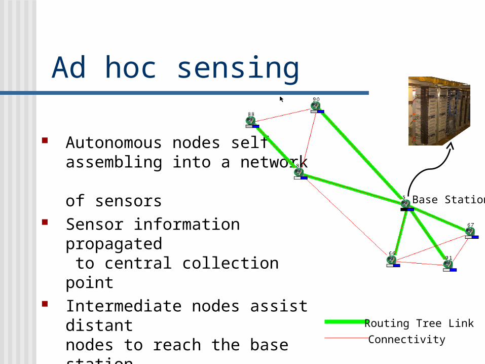
Ad hoc sensing
Autonomous nodes self assembling into a network of sensors
Sensor information propagated to central collection point
Intermediate nodes assist distant nodes to reach the base station
Connectivity and error rates used to infer distance
Routing Tree Link
Connectivity
Base Station
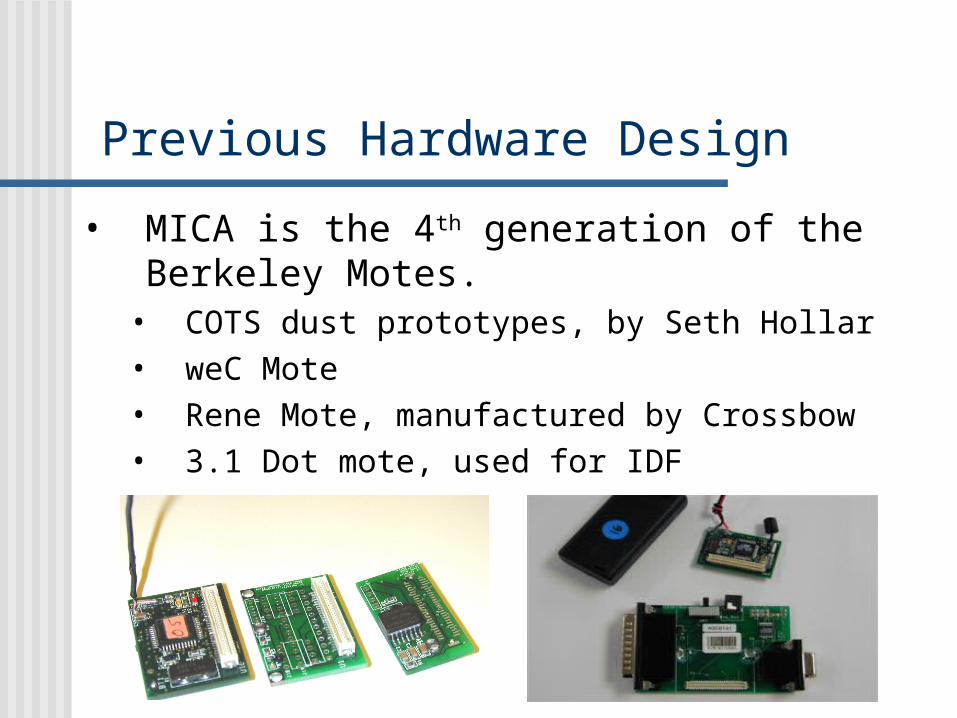
Previous Hardware Design
• MICA is the 4th generation of the Berkeley Motes.
• COTS dust prototypes, by Seth Hollar• weC Mote• Rene Mote, manufactured by Crossbow• 3.1 Dot mote, used for IDF
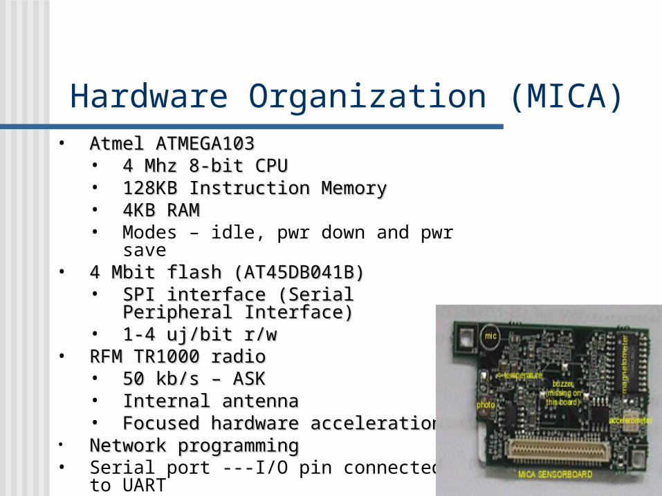
Hardware Organization (MICA)• Atmel ATMEGA103 Atmel ATMEGA103
• 4 Mhz 8-bit CPU4 Mhz 8-bit CPU• 128KB Instruction Memory128KB Instruction Memory• 4KB RAM4KB RAM• Modes – idle, pwr down and pwr
save• 4 Mbit flash (AT45DB041B)4 Mbit flash (AT45DB041B)
• SPI interface (SPI interface (Serial Peripheral Serial Peripheral InterfaceInterface))
• 1-4 uj/bit r/w1-4 uj/bit r/w• RFM TR1000 radioRFM TR1000 radio
• 50 kb/s – ASK50 kb/s – ASK• Internal antennaInternal antenna• Focused hardware accelerationFocused hardware acceleration
• Network programmingNetwork programming• Serial port ---I/O pin connected to UART
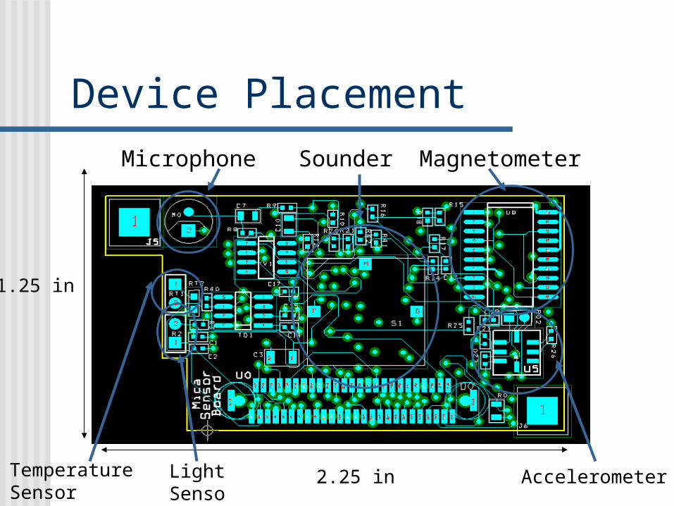
Device Placement
2.25 in
1.25 in
Microphone
AccelerometerLightSensor
TemperatureSensor
Sounder Magnetometer
More on Hardware•Two Board Sandwich
–Main CPU board with Radio Communication
–Secondary Sensor Board
•Allows for expansion and customization
•Current MICA sensors can include: Accelerometer, Magnetic Field,Temperature, Photo, Sounder, Microphone, Light, and RF Signal Strength
•Can control RF transmission strength & Sense Reception Strength
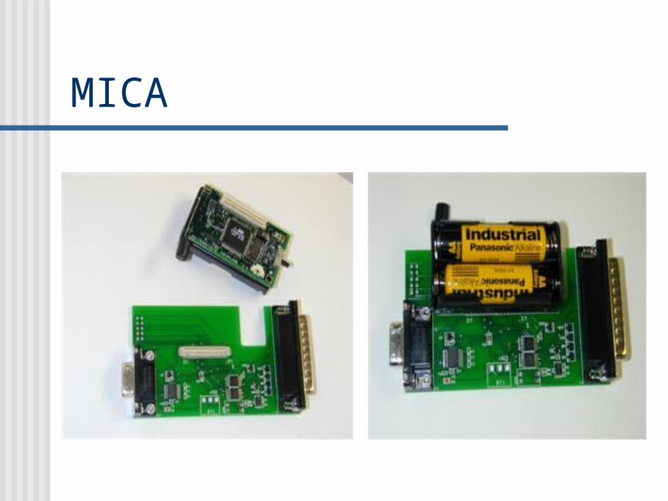
MICA

What is TinyOS?
• TinyOS is an event based operating environment design to work with embedded network sensors
• Designed to support concurrency intensive operations required by network sensors with minimal hardware requirements
• TinyOS was initially developed by the U.S. Berkeley EECS department
Software Challenge• Concurrency intensive operations
• Unsynchronized, Multiple , high data flow (sensor readings, forwarding data packets etc)
• Low memory data must be processed on the fly
• Low power consumption• Bit by Bit interaction with radio ( no buffering –
missed deadline lost data)• Small physical size – ( no multiple controllers,
direct interface with micro controller)• Modular – application specific
Tiny OS Overview• Event driven model.--- uses CPU efficiently• Two level scheduling ( Event and Tasks)• System composed of state machines• Each state machine is a TinyOS “component”• Command and event handlers transition a module from
one state to another• Quick, low overhead, non-blocking state transitions
• Many independent modules allowed to efficiently share a single execution context
• No kernel/user space differentiation• “Tasks” are used to perform computational work
• Run to completion, Atomic to respect to each other
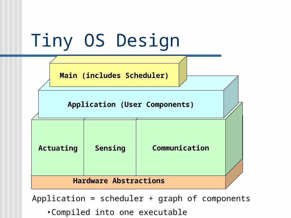
Tiny OS Design
Communication
Actuating Sensing Communication
Application (User Components)
Main (includes Scheduler)
Hardware Abstractions
Application = scheduler + graph of components
•Compiled into one executable
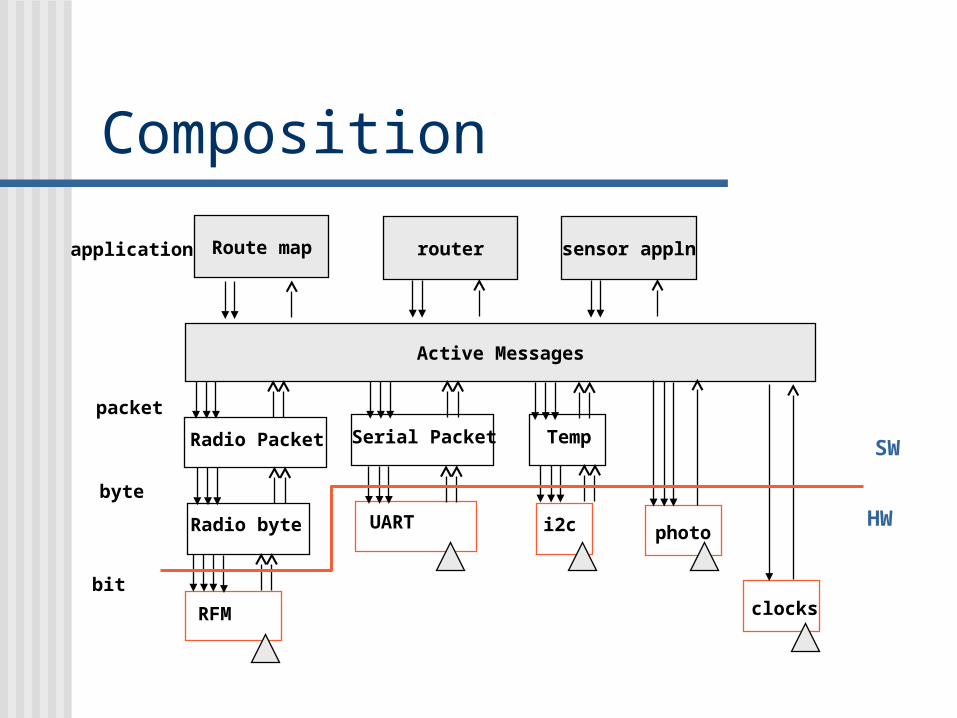
Composition
RFM
Radio byte
Radio Packet
UART
Serial Packet
i2c
Temp
photo
Active Messages
clocksbit
byte
packet
Route map router sensor applnapplication
HW
SW
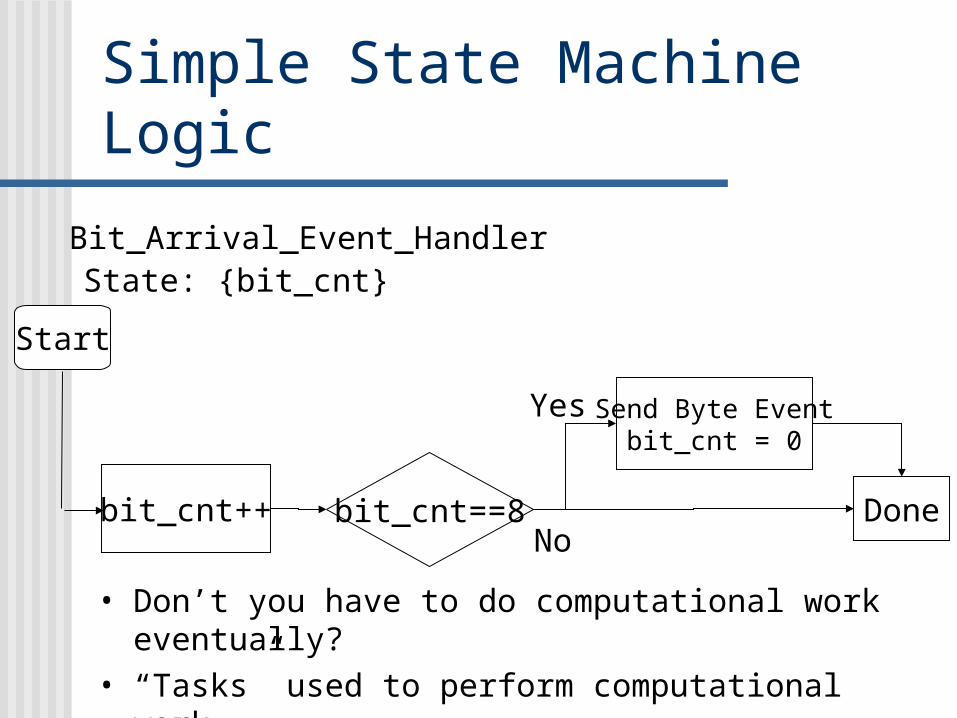
Simple State Machine Logic
bit_cnt++ bit_cnt==8
Send Byte Eventbit_cnt = 0
DoneNo
Yes
Bit_Arrival_Event_HandlerState: {bit_cnt}
Start
• Don’t you have to do computational work eventually?
• “Tasks” used to perform computational work
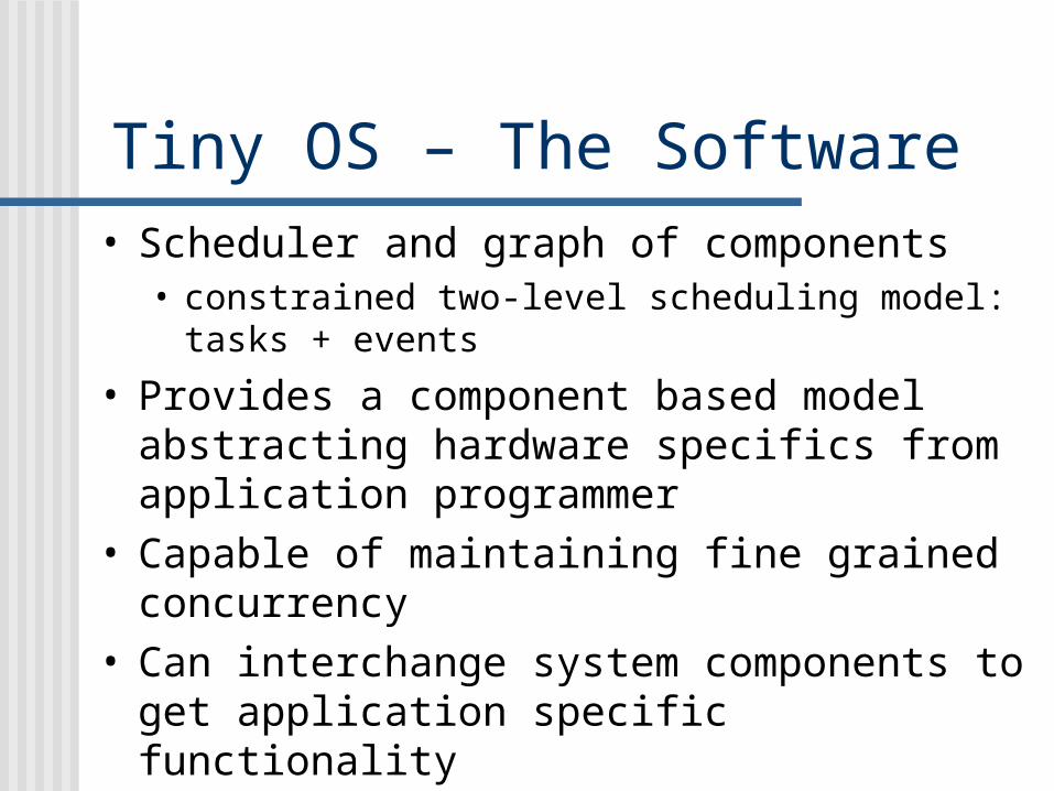
Tiny OS – The Software• Scheduler and graph of components
• constrained two-level scheduling model: tasks + events
• Provides a component based model abstracting hardware specifics from application programmer
• Capable of maintaining fine grained concurrency
• Can interchange system components to get application specific functionality
Tiny OS Component Design
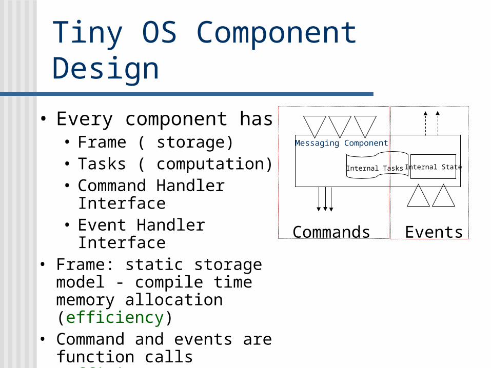
• Every component has• Frame ( storage)• Tasks ( computation)• Command Handler
Interface• Event Handler Interface
• Frame: static storage model - compile time memory allocation (efficiency)
• Command and events are function calls (efficiency)
Messaging Component
Internal StateInternal Tasks
Commands Events
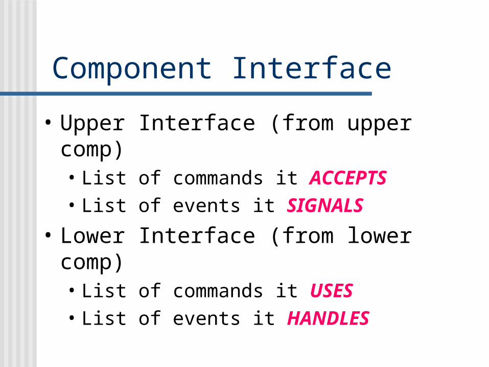
Component Interface
• Upper Interface (from upper comp)• List of commands it ACCEPTS• List of events it SIGNALS
• Lower Interface (from lower comp)• List of commands it USES• List of events it HANDLES
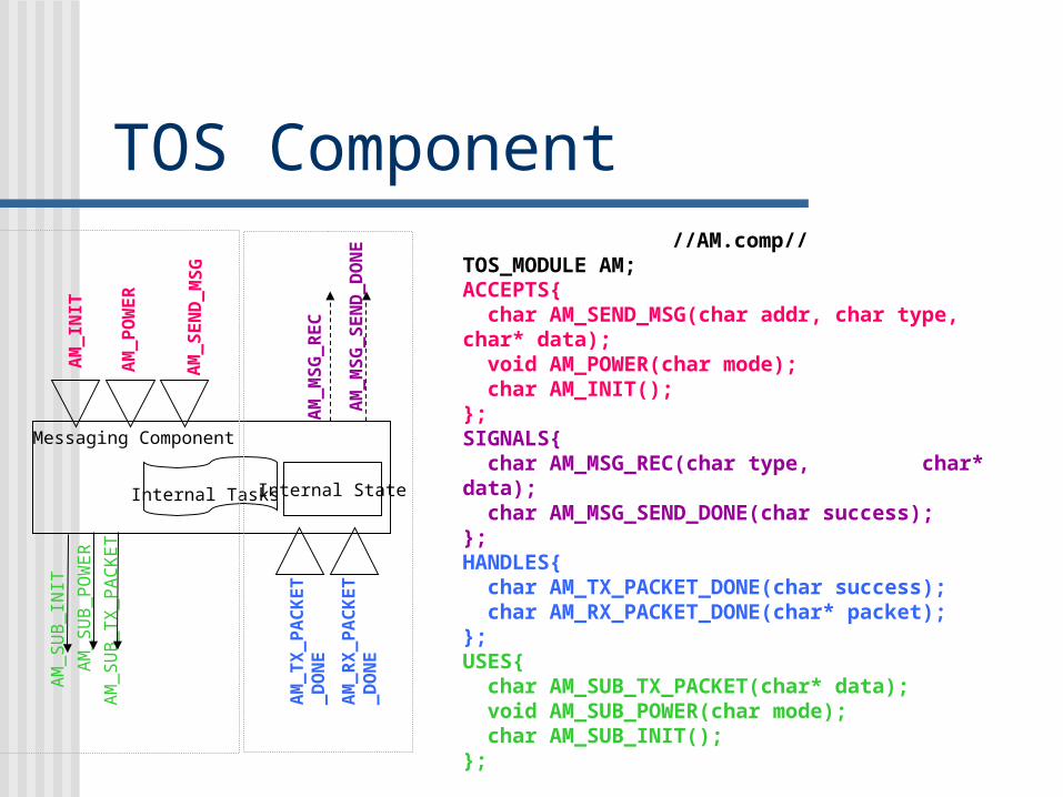
TOS Component//AM.comp//
TOS_MODULE AM;ACCEPTS{ char AM_SEND_MSG(char addr, char type, char* data); void AM_POWER(char mode); char AM_INIT();};SIGNALS{ char AM_MSG_REC(char type, char* data); char AM_MSG_SEND_DONE(char success);};HANDLES{ char AM_TX_PACKET_DONE(char success); char AM_RX_PACKET_DONE(char* packet);};USES{ char AM_SUB_TX_PACKET(char* data); void AM_SUB_POWER(char mode); char AM_SUB_INIT();};
Messaging Component
AM_SUB_INIT
AM_SUB_POWER
AM_SUB_TX_PACKET
AM_TX_PACKET
_DONE
AM_RX_PACKET
_DONE
Internal State
AM_INIT
AM_POWER
AM_MSG_REC
Internal Tasks
AM_SEND_MSG
AM_MSG_SEND_DONE
TOS Component
• FRAMES / MEMORY ALLOCATION• Keeps the state of the component
between invocation of its functions.• Statically allocated. ( mem req. is known
at compile time)• Defined as a global structure.
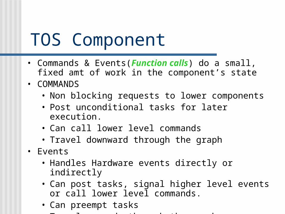
• Commands & Events(Function calls) do a small, fixed amt of work in the component’s state
• COMMANDS• Non blocking requests to lower components• Post unconditional tasks for later execution.• Can call lower level commands• Travel downward through the graph
• Events• Handles Hardware events directly or indirectly• Can post tasks, signal higher level events or call
lower level commands.• Can preempt tasks• Travel upwards through the graph.
• COMMANDS CANNOT SIGNAL EVENTS
TOS Component
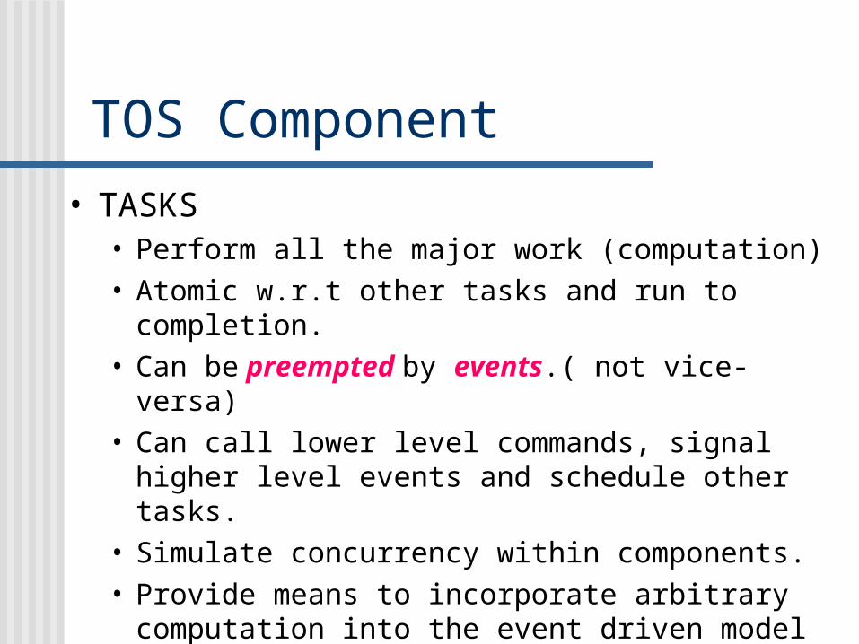
• TASKS• Perform all the major work (computation)• Atomic w.r.t other tasks and run to completion.• Can be preempted by events.( not vice-versa)• Can call lower level commands, signal higher
level events and schedule other tasks.• Simulate concurrency within components.• Provide means to incorporate arbitrary
computation into the event driven model
TOS Component
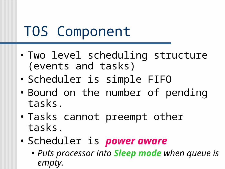
• Two level scheduling structure (events and tasks)
• Scheduler is simple FIFO• Bound on the number of pending
tasks.• Tasks cannot preempt other tasks.• Scheduler is power aware
• Puts processor into Sleep mode when queue is empty.
TOS Component
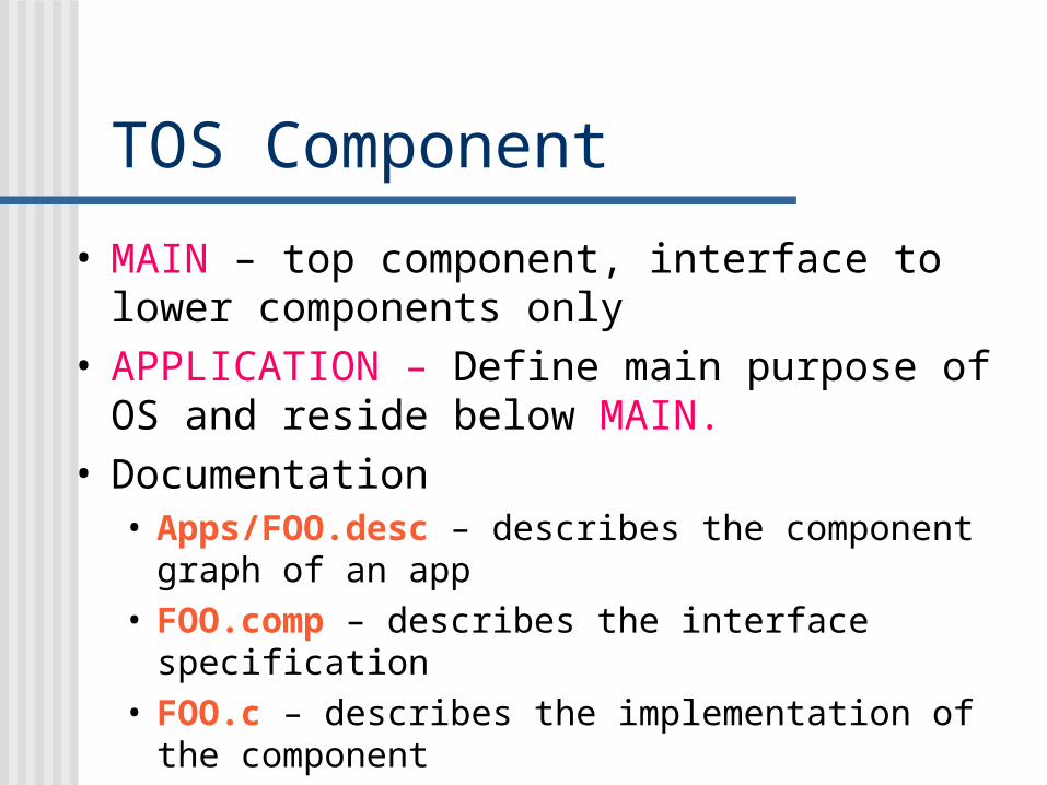
• MAIN – top component, interface to lower components only
• APPLICATION – Define main purpose of OS and reside below MAIN.
• Documentation• Apps/FOO.desc – describes the component
graph of an app• FOO.comp – describes the interface specification• FOO.c – describes the implementation of the
component
TOS Component
• Group certain components together to perform a certain function.
• These can be treated as a single entity.
• Example - GENERIC_COMM – used to handle radio communication
• There is no separate FOO.c for component groups.
TOS Component
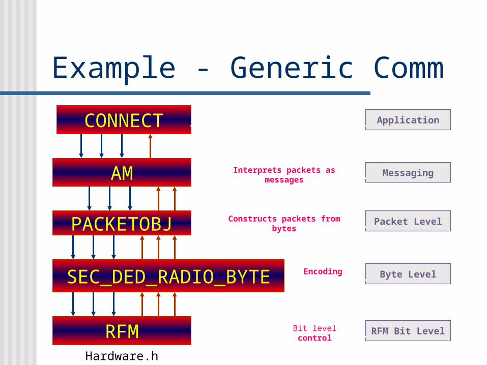
AM
PACKETOBJ
SEC_DED_RADIO_BYTE
RFMHardware.h
CONNECT
RFM Bit Level
Byte Level
Packet Level
Messaging
Application
Bit level control
Encoding
Constructs packets from bytes
Interprets packets as messages
Example - Generic Comm
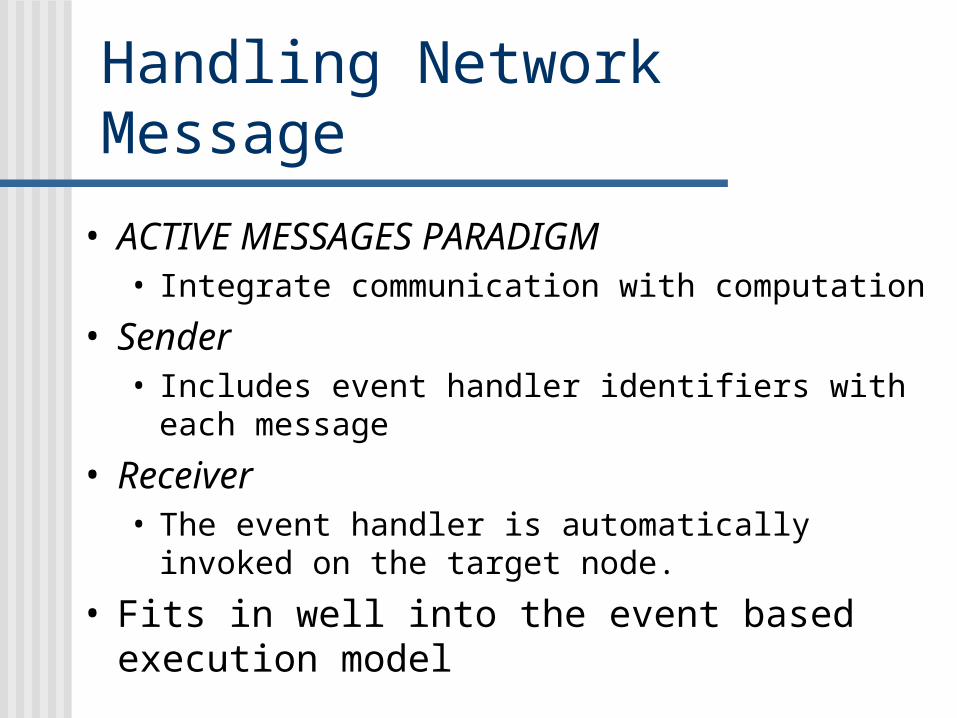
• ACTIVE MESSAGES PARADIGM• Integrate communication with computation
• Sender• Includes event handler identifiers with each
message
• Receiver• The event handler is automatically invoked on
the target node.
• Fits in well into the event based execution model
Handling Network Message
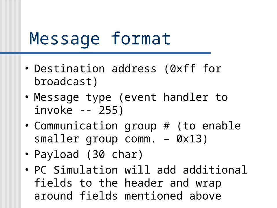
Message format
• Destination address (0xff for broadcast)• Message type (event handler to invoke
-- 255)• Communication group # (to enable
smaller group comm. – 0x13)• Payload (30 char) • PC Simulation will add additional fields
to the header and wrap around fields mentioned above
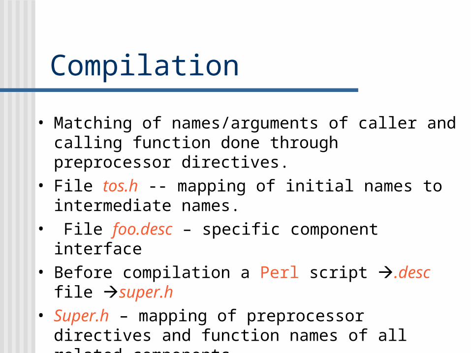
• Matching of names/arguments of caller and calling function done through preprocessor directives.
• File tos.h -- mapping of initial names to intermediate names.
• File foo.desc – specific component interface • Before compilation a Perl script .desc file
super.h • Super.h – mapping of preprocessor directives and
function names of all related components.
Compilation
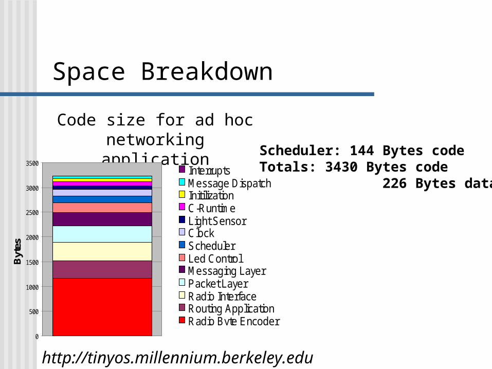
Code size for ad hoc networkingapplication
Scheduler: 144 Bytes codeTotals: 3430 Bytes code 226 Bytes data
http://tinyos.millennium.berkeley.edu
0
500
1000
1500
2000
2500
3000
3500
Byt
es
InterruptsMessage DispatchInitilizationC-RuntimeLight SensorClockSchedulerLed ControlMessaging LayerPacket LayerRadio InterfaceRouting ApplicationRadio Byte Encoder
Space Breakdown
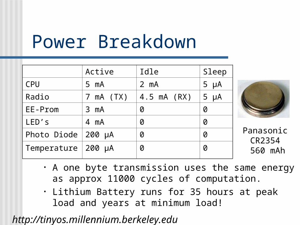
• A one byte transmission uses the same energy as approx 11000 cycles of computation.
• Lithium Battery runs for 35 hours at peak load and years at minimum load!
Active Idle Sleep
CPU 5 mA 2 mA 5 μA
Radio 7 mA (TX) 4.5 mA (RX) 5 μA
EE-Prom 3 mA 0 0
LED’s 4 mA 0 0
Photo Diode 200 μA 0 0
Temperature 200 μA 0 0
Panasonic CR2354
560 mAh
http://tinyos.millennium.berkeley.edu
Power Breakdown
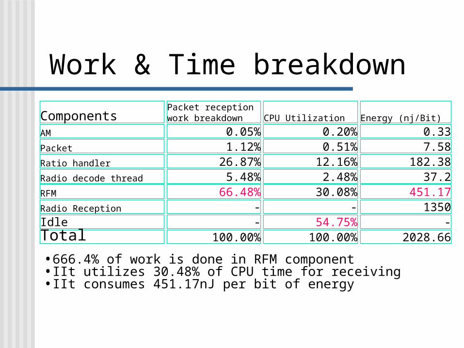
•666.4% of work is done in RFM component•IIt utilizes 30.48% of CPU time for receiving•IIt consumes 451.17nJ per bit of energy
ComponentsPacket reception work breakdown CPU Utilization Energy (nj/Bit)
AM 0.05% 0.20% 0.33Packet 1.12% 0.51% 7.58Ratio handler 26.87% 12.16% 182.38Radio decode thread 5.48% 2.48% 37.2RFM 66.48% 30.08% 451.17Radio Reception - - 1350Idle - 54.75% -Total 100.00% 100.00% 2028.66
Work & Time breakdown
Panasonic CR2354
560 mAh
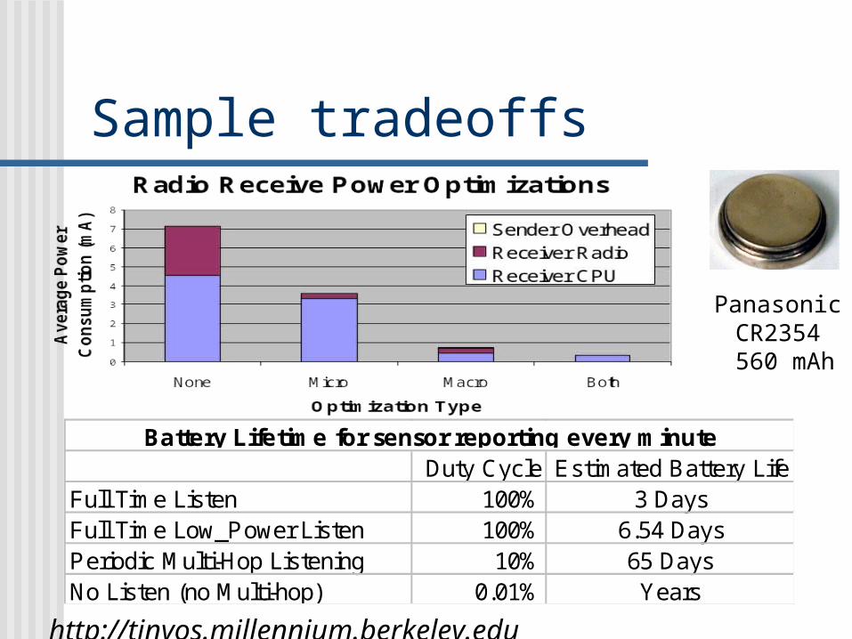
Duty Cycle Estimated Battery LifeFull Time Listen 100% 3 DaysFull Time Low_Power Listen 100% 6.54 DaysPeriodic Multi-Hop Listening 10% 65 DaysNo Listen (no Multi-hop) 0.01% Years
Battery Lifetime for sensor reporting every minute
http://tinyos.millennium.berkeley.edu
Sample tradeoffs
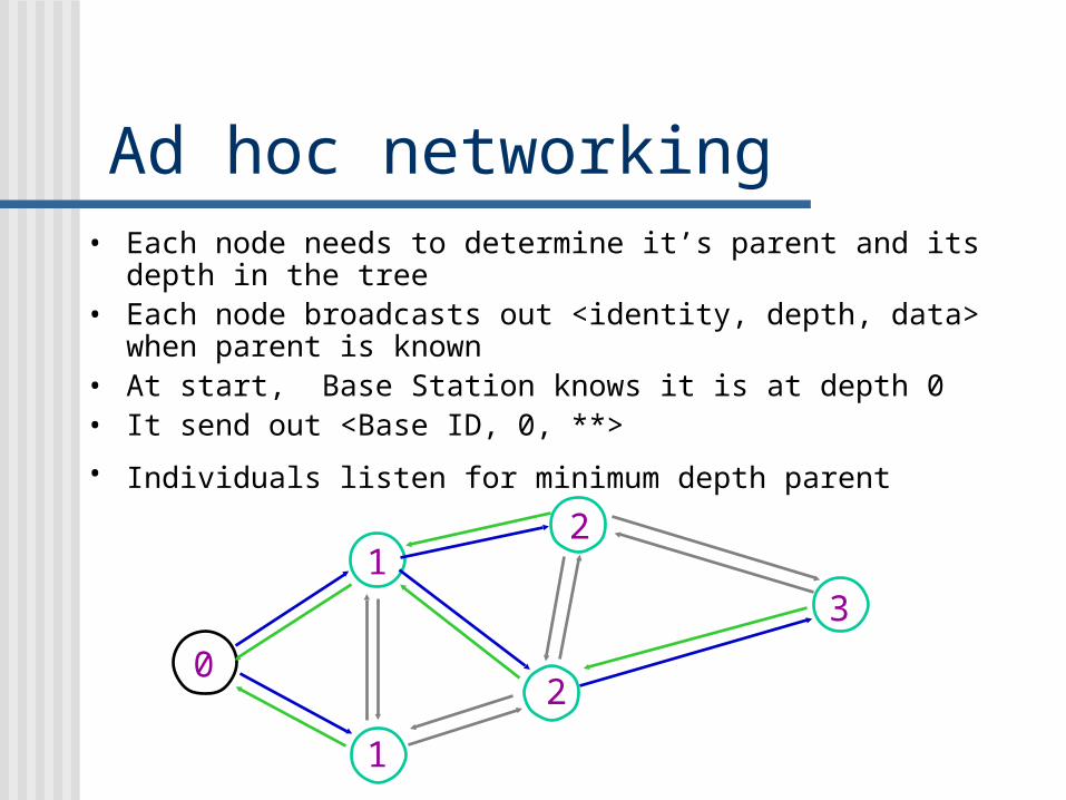
Ad hoc networking• Each node needs to determine it’s parent and its depth in the
tree• Each node broadcasts out <identity, depth, data> when
parent is known• At start, Base Station knows it is at depth 0• It send out <Base ID, 0, **>
• Individuals listen for minimum depth parent
0
1
1
2
2
3

Conclusions• Small memory footprint
• Non-preemptable FIFO task scheduling• Power efficient
• Put micro controller and radio to sleep• Efficient modularity
• Function call (event, command) interface between components
• Concurrency-intensive operations • Event-driven architecture• Efficient interrupts/events handling (function calls,
no user/kernel boundary)• Real-time
• Non-preemptable FIFO task scheduling• NO real-time guarantees or overload protection
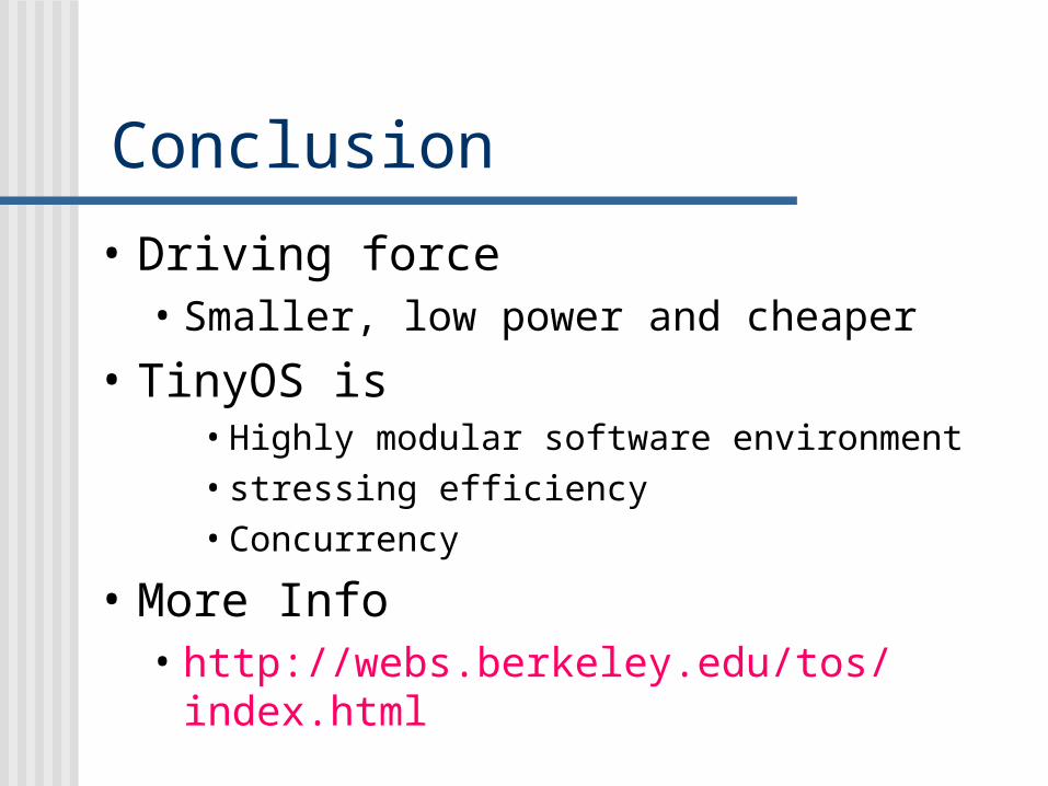
Conclusion
• Driving force • Smaller, low power and cheaper
• TinyOS is• Highly modular software environment • stressing efficiency • Concurrency
• More Info• http://webs.berkeley.edu/tos/index.html