titanium – stainless steel brazing using...
TRANSCRIPT
Special Issue | October 2014 219
BARC NEWSLETTERFounder’s DayTITANIUM – STAINLESS STEEL BRAZING
USING AG-BASED ALLOYS
A. Laik and G.K. DeyMaterials Science Division
andA.A. Shirzadi
Materials Engineering, The Open University, Milton Keynes MK7 6AA, United Kingdom
Abstract
A detailed characterization of vacuum brazed joints of titanium and stainless steel type 304L, using three Ag-based
brazing alloys, Cusil, Ticusil and Silver-ABA has been carried out. The intermetallic compounds formed at the braze
zone due to interaction of the joining components with the brazing alloys were identified. The microstructural
evolution at the interfaces and the mechanisms of brazing in the three cases are compared.
This paper received the Best Poster, 2nd Prize (Materials Science) at the International Conference on Electron Microscopy & XXXIV Annual Meeting of EMSI, Kolkata, 3-5 July, 2013
Introduction
Both titanium and stainless steel (SS) are widely used
as engineering materials in industries due to their
excellent mechanical properties as well as corrosion
resistance. The extensive use of Ti and its alloys in
various sectors, for example, aerospace, transportation,
chemical, nuclear and power generation, requires them
to be joined to other materials for integration and
fabrication of various components [1, 2]. Of particular
interest to the nuclear industry, is the application of Ti
in fabricating the dissolvers of spent nuclear fuel used
in reprocessing plants. This requires it to be joined to
the piping of the plant, which is generally made of
stainless steel (SS) [3].
Conventional fusion welding has not been a good
choice since it needs to be performed in inert
atmosphere due to the reactive nature of Ti, and the
significant difference in physico-chemical properties of
the two materials that lead to chemical, mechanical and
structural inhomogeneities [7]. Although the progress
of research on diffusion bonding of SS to Ti with
suitable interlayers has led to some success, formation
of undesirable intermetallic compounds of various
combinations such as Ti–Fe, Ti–Cr, Ti–Ni could not be
completely eliminated [2, 9]. The formation of these
intermetallics produce residual stresses originating
from a mismatch in their thermal expansion [7, 10,
11]. Further, the method is expensive and not an
obvious choice for mass production [8]. In comparison
to these techniques, vacuum brazing offers two major
advantages: (a) low thermal residual stresses in the
joints, as a major part of the stresses generated due to
differential contraction of the two materials is relieved
by plastic deformation of the ductile braze alloys, and
(b) a low compressive stress is required for joining [7].
Dececco and Parks [12] suggested the use of silver
and its alloys to braze Ti and since then various Ag-
based filler alloys have been extensively used for the
brazing of Ti and its alloys, primarily due to good flow
characteristics of these filler alloys and high strength
and adequate ductility of these brazed joints.
The present study compares the brazing characteristics
of stainless steel/titanium brazing using different Ag-
Home
NEXTPREVIOUS ê ê
CONTENTS
220 Special Issue | October 2014
BARC NEWSLETTERFounder’s Daybased brazing alloys. The mechanisms of brazing and
microstructural evolution at the interfaces are also
determined.
Experimental Procedure
The base materials used in the experiments were
annealed plates of commercially pure grade-2 titanium
(ASTM B265) and austenitic stainless steel (SS 304L).
The nominal compositions of these materials are given
in Table 1. Specimens of Ti grade 2 and SS 304L, in
the form of cylindrical pieces with dimensions of 35
mm length and 14 mm diameter were vacuum brazed
using 50 mm thick foils of Ag-based alloys Cusil, Ticusil
and Silver-ABA at temperatures 835 oC, 920 oC and
930 oC, respectively. The nominal compositions of
these alloys are given in Table 2. The joining faces
of the pieces were ground with successive grades
of emery papers up to 1200 grit, followed by 1 mm
diamond polish. Prior to brazing, all the components
were ultrasonically cleaned with ethyl alcohol followed
by acetone. The brazing operation was carried out in a
furnace under vacuum of 5 X 10⁻⁵ mbar.
scanning electron microscope (SEM), energy dispersive
spectrometry (EDS), electron probe microanalyser
(EPMA) and transmission electron microscope (TEM).
Results
Brazing with Silver-ABA
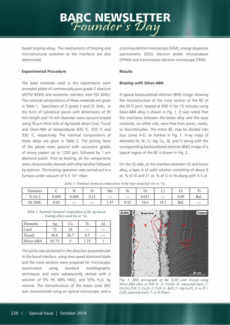
A typical backscattered electron (BSE) image showing
the microstructure of the cross section of the BZ of
the SS-Ti joint, brazed at 930 oC for 15 minutes using
Silver-ABA alloy is shown in Fig. 1. It was noted that
the interfaces between the braze alloy and the base
materials, on either side, were free from pores, cracks,
or discontinuities. The entire BZ, may be divided into
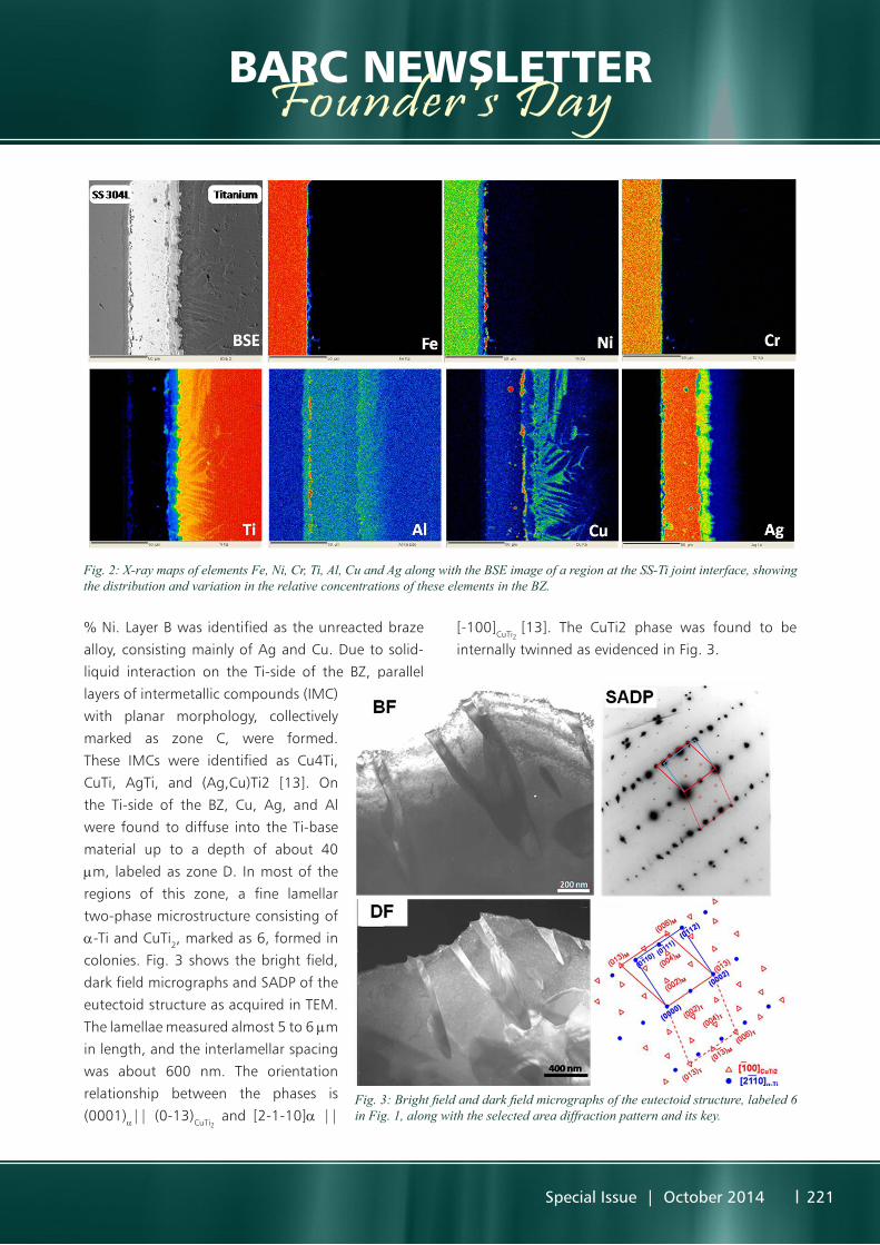
four zones A-D, as marked in Fig. 1. X-ray maps of
elements Fe, Ni, Cr, Ag, Cu, Al, and Ti along with the
corresponding backscattered electron (BSE) image of a
typical region of the BZ is shown in Fig. 2.
On the SS-side, at the interface between SS and braze
alloy, a layer A of solid solution consisting of about 5
at. % of Al and 21 at. % of Cr in Fe along with 5.5 at.
Elements C H O Mn Si Ni Cr Fe TiTi Gr-2 0.009 0.008 0.12 --- --- 0.011 --- 0.09 Bal.SS 304L 0.02 --- --- 1.47 0.52 10.6 19.1 Bal. ---
Table 1: Nominal chemical composition of the base materials (in wt. %).
Table 2. Nominal chemical composition of the Ag-based brazing alloys used (in wt. %).
Elements Ag Cu Ti AlCusil 72 28 --- ---Ticusil 68.8 26.7 4.5 ---Silver-ABA 92.75 5 1.25 1
The joints was sectioned in the direction perpendicular
to the bond interface, using slow speed diamond blade
and the cross-sections were prepared for microscopic
examination using standard metallographic
techniques and were subsequently etched with a
solution of 5% HF, 40% HNO3 and 55% H2O, by
volume. The microstructure of the braze zone (BZ)
was characterized using an optical microscope, and a
Fig. 1: BSE micrograph of the Ti-SS joint brazed using Silver-ABA alloy at 930 oC. A: Fe(Al), B: unreacted layer, 1: (Ni,Fe)2TiAl, 2: Cu4Ti, 3: CuTi, 4: AgTi, 5: (Ag,Cu)Ti2, 6: a-Ti + CuTi2 eutectoid layer, 7: a-Ti Plates.
Special Issue | October 2014 221
BARC NEWSLETTERFounder’s Day
% Ni. Layer B was identified as the unreacted braze
alloy, consisting mainly of Ag and Cu. Due to solid-
liquid interaction on the Ti-side of the BZ, parallel
layers of intermetallic compounds (IMC)
with planar morphology, collectively
marked as zone C, were formed.
These IMCs were identified as Cu4Ti,
CuTi, AgTi, and (Ag,Cu)Ti2 [13]. On
the Ti-side of the BZ, Cu, Ag, and Al
were found to diffuse into the Ti-base
material up to a depth of about 40
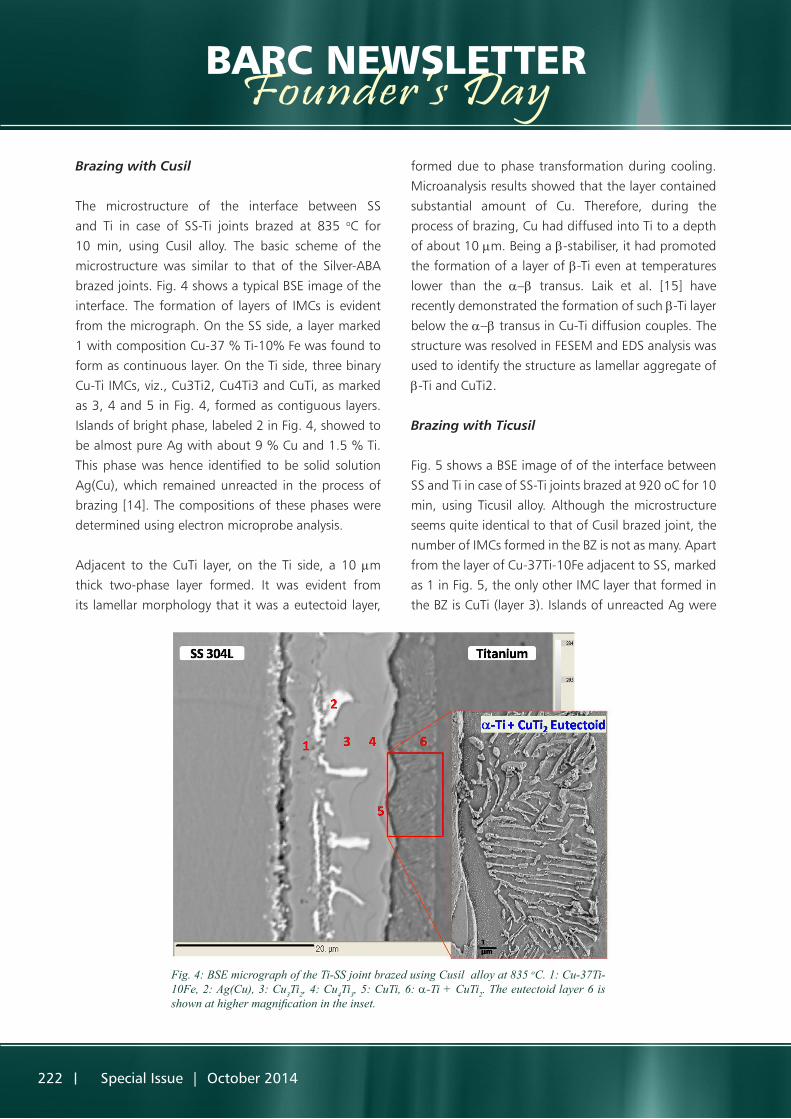
mm, labeled as zone D. In most of the
regions of this zone, a fine lamellar
two-phase microstructure consisting of
a-Ti and CuTi2, marked as 6, formed in
colonies. Fig. 3 shows the bright field,
dark field micrographs and SADP of the
eutectoid structure as acquired in TEM.
The lamellae measured almost 5 to 6 mm
in length, and the interlamellar spacing
was about 600 nm. The orientation
relationship between the phases is
(0001)a|| (0-13)CuTi2 and [2-1-10]a ||
[-100]CuTi2 [13]. The CuTi2 phase was found to be
internally twinned as evidenced in Fig. 3.
Fig. 2: X-ray maps of elements Fe, Ni, Cr, Ti, Al, Cu and Ag along with the BSE image of a region at the SS-Ti joint interface, showing the distribution and variation in the relative concentrations of these elements in the BZ.
Fig. 3: Bright field and dark field micrographs of the eutectoid structure, labeled 6 in Fig. 1, along with the selected area diffraction pattern and its key.
222 Special Issue | October 2014
BARC NEWSLETTERFounder’s DayBrazing with Cusil
The microstructure of the interface between SS
and Ti in case of SS-Ti joints brazed at 835 oC for
10 min, using Cusil alloy. The basic scheme of the
microstructure was similar to that of the Silver-ABA
brazed joints. Fig. 4 shows a typical BSE image of the
interface. The formation of layers of IMCs is evident
from the micrograph. On the SS side, a layer marked
1 with composition Cu-37 % Ti-10% Fe was found to
form as continuous layer. On the Ti side, three binary
Cu-Ti IMCs, viz., Cu3Ti2, Cu4Ti3 and CuTi, as marked
as 3, 4 and 5 in Fig. 4, formed as contiguous layers.
Islands of bright phase, labeled 2 in Fig. 4, showed to
be almost pure Ag with about 9 % Cu and 1.5 % Ti.
This phase was hence identified to be solid solution
Ag(Cu), which remained unreacted in the process of
brazing [14]. The compositions of these phases were
determined using electron microprobe analysis.
Adjacent to the CuTi layer, on the Ti side, a 10 mm
thick two-phase layer formed. It was evident from
its lamellar morphology that it was a eutectoid layer,
formed due to phase transformation during cooling.
Microanalysis results showed that the layer contained
substantial amount of Cu. Therefore, during the
process of brazing, Cu had diffused into Ti to a depth
of about 10 mm. Being a b-stabiliser, it had promoted
the formation of a layer of b-Ti even at temperatures
lower than the a-b transus. Laik et al. [15] have
recently demonstrated the formation of such b-Ti layer
below the a-b transus in Cu-Ti diffusion couples. The
structure was resolved in FESEM and EDS analysis was
used to identify the structure as lamellar aggregate of
b-Ti and CuTi2.
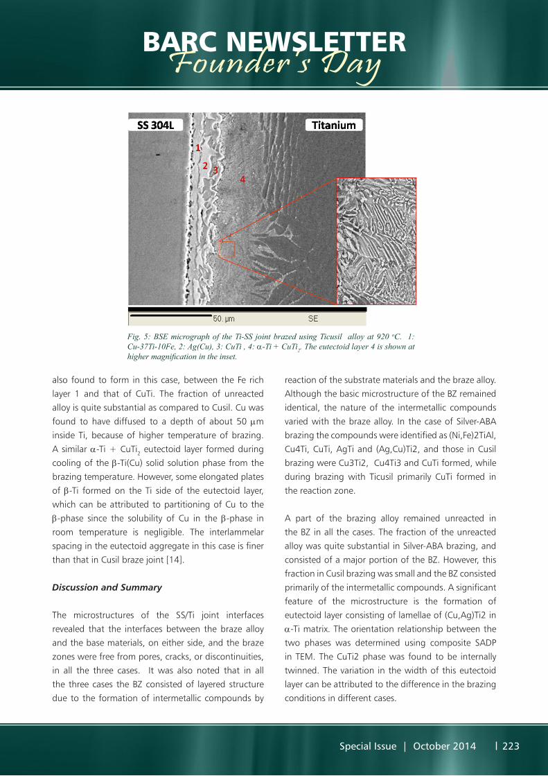
Brazing with Ticusil
Fig. 5 shows a BSE image of of the interface between
SS and Ti in case of SS-Ti joints brazed at 920 oC for 10
min, using Ticusil alloy. Although the microstructure
seems quite identical to that of Cusil brazed joint, the
number of IMCs formed in the BZ is not as many. Apart
from the layer of Cu-37Ti-10Fe adjacent to SS, marked
as 1 in Fig. 5, the only other IMC layer that formed in
the BZ is CuTi (layer 3). Islands of unreacted Ag were
Fig. 4: BSE micrograph of the Ti-SS joint brazed using Cusil alloy at 835 oC. 1: Cu-37Ti-10Fe, 2: Ag(Cu), 3: Cu3Ti2, 4: Cu4Ti3, 5: CuTi, 6: a-Ti + CuTi2. The eutectoid layer 6 is shown at higher magnification in the inset.
Special Issue | October 2014 223
BARC NEWSLETTERFounder’s Day
also found to form in this case, between the Fe rich
layer 1 and that of CuTi. The fraction of unreacted
alloy is quite substantial as compared to Cusil. Cu was
found to have diffused to a depth of about 50 mm
inside Ti, because of higher temperature of brazing.
A similar a-Ti + CuTi2 eutectoid layer formed during
cooling of the b-Ti(Cu) solid solution phase from the
brazing temperature. However, some elongated plates
of b-Ti formed on the Ti side of the eutectoid layer,
which can be attributed to partitioning of Cu to the
b-phase since the solubility of Cu in the b-phase in
room temperature is negligible. The interlammelar
spacing in the eutectoid aggregate in this case is finer
than that in Cusil braze joint [14].
Discussion and Summary
The microstructures of the SS/Ti joint interfaces
revealed that the interfaces between the braze alloy
and the base materials, on either side, and the braze
zones were free from pores, cracks, or discontinuities,
in all the three cases. It was also noted that in all
the three cases the BZ consisted of layered structure
due to the formation of intermetallic compounds by
reaction of the substrate materials and the braze alloy.
Although the basic microstructure of the BZ remained
identical, the nature of the intermetallic compounds
varied with the braze alloy. In the case of Silver-ABA
brazing the compounds were identified as (Ni,Fe)2TiAl,
Cu4Ti, CuTi, AgTi and (Ag,Cu)Ti2, and those in Cusil
brazing were Cu3Ti2, Cu4Ti3 and CuTi formed, while
during brazing with Ticusil primarily CuTi formed in
the reaction zone.
A part of the brazing alloy remained unreacted in
the BZ in all the cases. The fraction of the unreacted
alloy was quite substantial in Silver-ABA brazing, and
consisted of a major portion of the BZ. However, this
fraction in Cusil brazing was small and the BZ consisted
primarily of the intermetallic compounds. A significant
feature of the microstructure is the formation of
eutectoid layer consisting of lamellae of (Cu,Ag)Ti2 in
a-Ti matrix. The orientation relationship between the
two phases was determined using composite SADP
in TEM. The CuTi2 phase was found to be internally
twinned. The variation in the width of this eutectoid
layer can be attributed to the difference in the brazing
conditions in different cases.
Fig. 5: BSE micrograph of the Ti-SS joint brazed using Ticusil alloy at 920 oC. 1: Cu-37Ti-10Fe, 2: Ag(Cu), 3: CuTi , 4: a-Ti + CuTi2. The eutectoid layer 4 is shown at higher magnification in the inset.
224 Special Issue | October 2014
BARC NEWSLETTERFounder’s DayAcknowledgements
The authors are thankful to Shri P. Mishra, Materials
Processing Division, for providing the Silver-ABA foils.
The authors would also like to thank Dr. R. Tewari for
the TEM analysis of the samples. The assistance of Shri
P. G. Adiga in conducting the brazing experiments is
gratefully acknowledged.
References
1. A. Shapiro and A. Rabinkin: Weld. J., 2003, vol.
83, pp. 36–43.
2. S. Kundu, M. Ghosh, A. Laik, K. Bhanumurthy, G.
B. Kale, and S. Chatterjee: Mater Sci. Eng. A, 2005,
vol. 407, pp. 36–43.
3. U. K. Mudali, B. M. Ananda Rao, K. Shanmugam,
R. Nataraj, and B. Raj: J. Nucl. Mater., 2003, vol.
321, pp. 40–48.
4. P. He, J. Zang, R. Zhou, and X. Li: Mater. Charact.,
1999, vol. 43, pp. 287–292.
5. N. Orhan, T. I. Khan, and M. Eroglu: Scripta Mater.,
2001, vol. 45, pp. 441–446.
6. J. G. Lee, S. J. Hong, M. Lee, and C. Rhee: Scripta
Mater., 2009, vol. 395, pp. 145–149.
7. X. Yue, P. He, J. C. Zhang, and F. Q. Zhu: Mater
Charact., 2008, vol. 59, pp. 1721–1727.
8. A. Elrefaey and W. Tillmann: Weld. J., 2008, vol.
87, pp. 113s–118s.
9. J. G. Lee, S. J. Hong, M. K. Lee, and C. K. Rhee: J.
Nucl. Mater., 2009, vol. 395, pp. 145–149.
10. P. He, X.Yue, and J. H. Zhang: Mater. Sci. Eng. A,
2008, vol. 486, pp. 171–176.
11. M. Ghosh, S. Chartterjee, and B. Mishra: Mater.
Sci. Eng. A, 2003, vol. 363, pp. 268–274.
12. N. A. Dececco and J. N. Parks: Weld. J., 1953, vol.
32, pp. 1071–1081.
13. A. Laik, A. A. Shirzadi, R. Tewari, Anish Kumar, T.
Jayakumar, G. K. Dey: Metall. and Mater. Trans. A,
2013, vol. 44A, pp. 2212-2225.
14. A. Laik, A. A. Shirzadi, G. K. Dey, Intl. Conf. Electron
Microscopy and XXXIV Annual Meeting of EMSI,
Kolkata, 3-5 July, 2013, p. 219.
15. A Laik, K. Bhanumurthy, G. B. Kale, B. P.
Kashyap: Int. J. Mater. Res., 2012, vol. 103, pp.
661-672.