title to go here - ccreee
TRANSCRIPT

TITLE TO GO HERE
TEXT TO GO HERE
Click to edit Master title style
Click to edit Master text stylesSecond levelThird level
Fourth levelFifth level
Introduction to Grid Modelling
23rd March 2021

Team
Professor Chandrabhan Sharma Dr Sanjay Bahadoorsingh
23rd March 2021 Grid Modelling 2

Learning Outcomes
• Appreciate grid modelling fundamentals.
• Appreciate the requirements to build a power system model in software.
• Appreciate steady state studies (power flow and short circuit analysis) and transient analysis.
• Identify the data requirements for accurate modelling and analyses.
23rd March 2021 Grid Modelling 3

Power Systems Basics
23rd March 2021 Grid Modelling 4

Simple Power System
Every power system has three major components
• Generation: source of power, ideally with a specified voltage and frequency
• Transmission system: transmits power; ideally as a perfect conductor
• Load: consumes power; ideally with a constant resistive value
23rd March 2021 Grid Modelling 5

Modelling Power Systems
Why model Power Systems?
Need to simulate real system to evaluate designs and
operation tasks.
Simpler and more cost effective to implement.
23rd March 2021 Grid Modelling 6

Power Systems Analysis
• Safe
• Reliable
• Economical
Modelling Power Systems
• Planning & Expansion
• Operations
• Types of analysis
• Transmission line performance
• Power flow analysis
• Contingency analysis
• Economic generation scheduling
• Fault analysis
• Transient studies
• Requires component modeling
Practical Power Systems
23rd March 2021 Grid Modelling 7
23rd March 2021 Grid Modelling 8
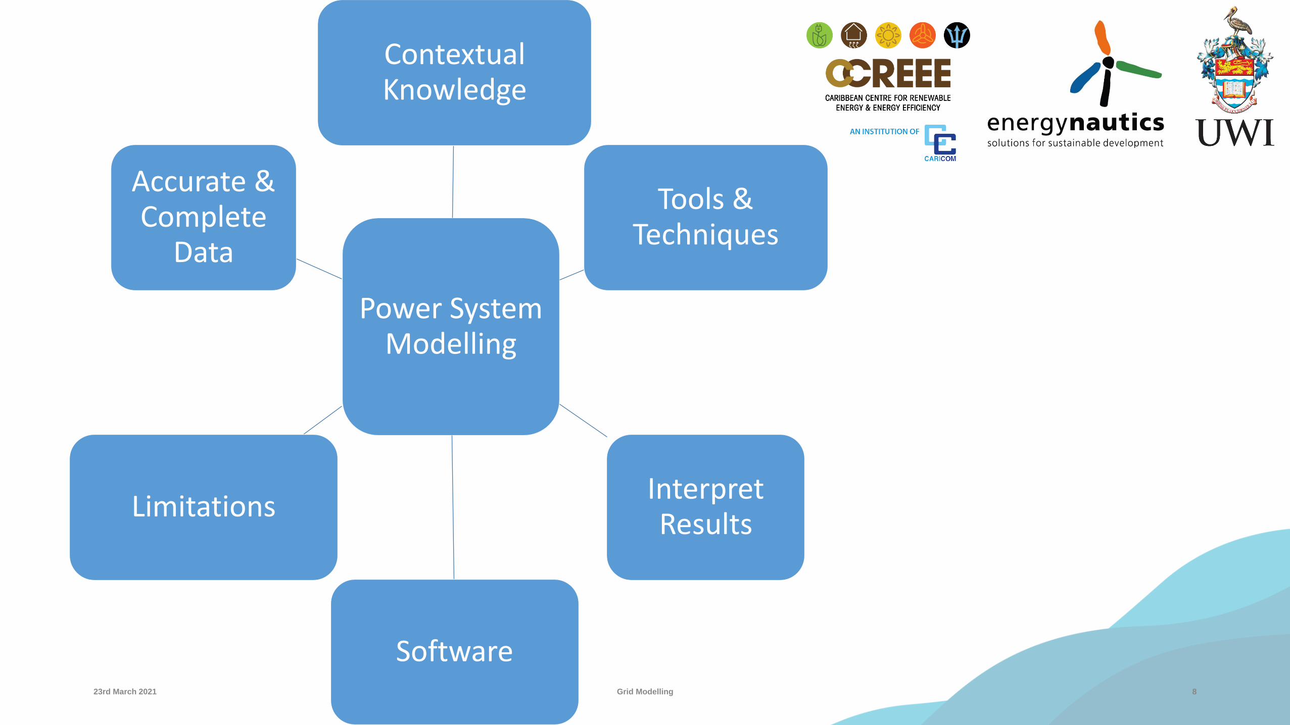
Power System Modelling
Contextual Knowledge
Tools & Techniques
Interpret Results
Software
Limitations
Accurate & Complete
Data

Develop Technical Capacity
• Planning
• Software familiarity
• Missing data for models
• Operational
• Data capture
• Data analysis
• Optimize
• Reduce outsourcing costs
23rd March 2021 Grid Modelling 9

A Story of Cascading Outages
1023rd March 2021 Grid Modelling

A Story of Cascading Outages
A line failure occurs and causes and overload on a neighbouring line
1123rd March 2021 Grid Modelling
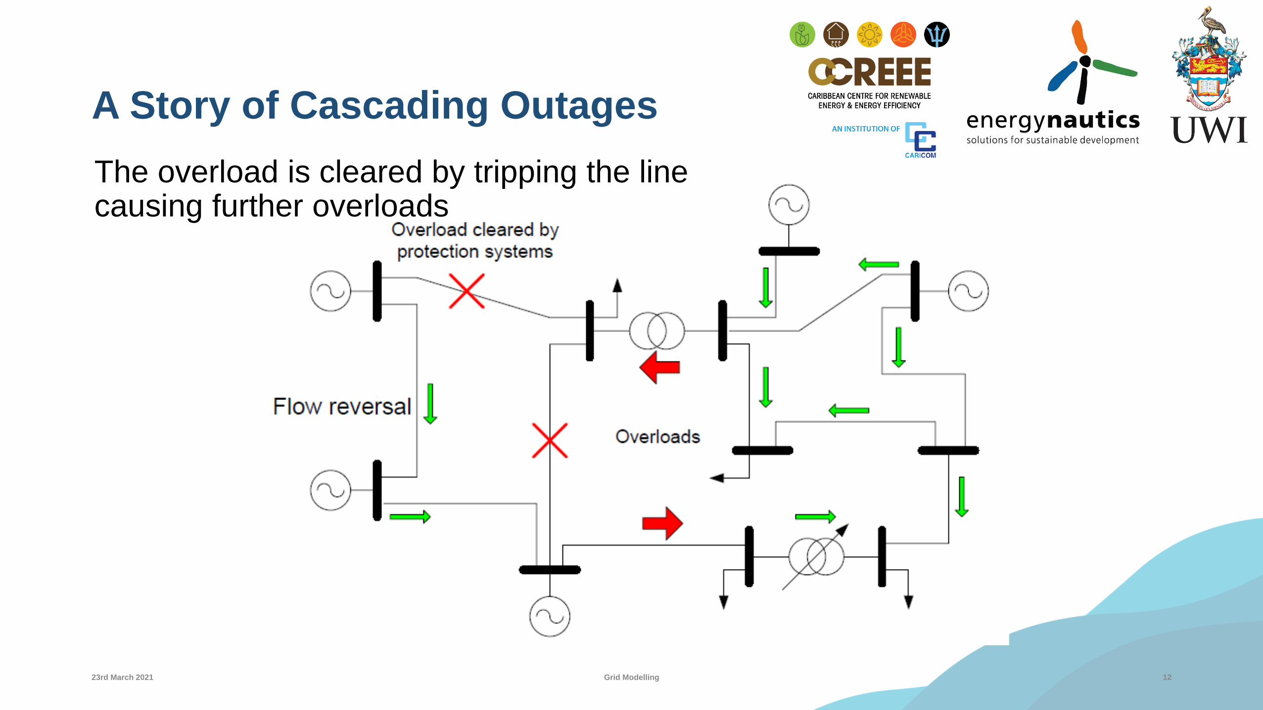
A Story of Cascading Outages
The overload is cleared by tripping the line causing further overloads
1223rd March 2021 Grid Modelling

A Story of Cascading Outages
Overloads are cleared, but some generators have no more load
1323rd March 2021 Grid Modelling
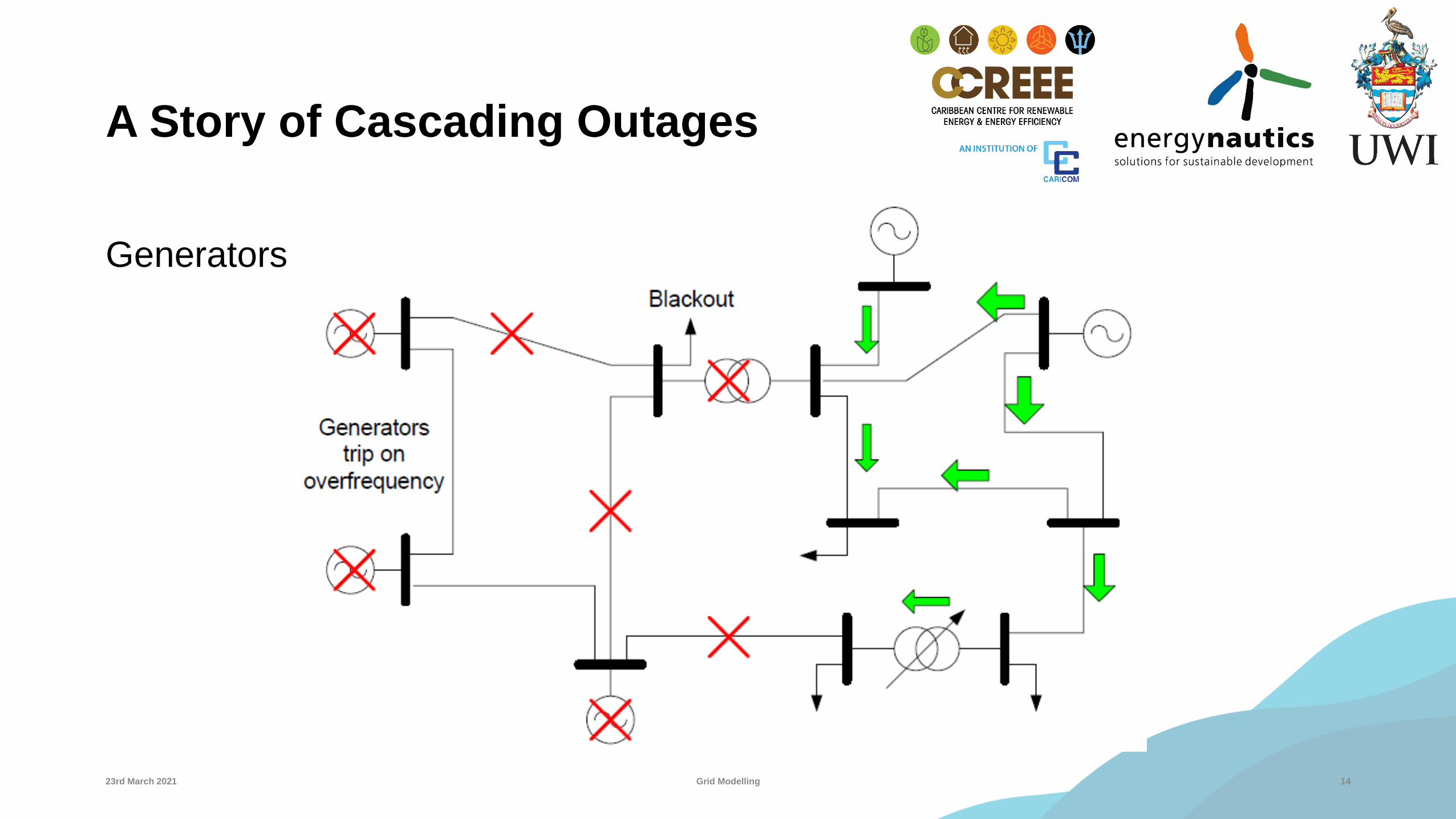
A Story of Cascading Outages
Generators trip by the action of overfrequency protection
1423rd March 2021 Grid Modelling

A Story of Cascading Outages
The remaining generators are not enough to supply all the remaining load. They trip by the action of underfrequency protection
1523rd March 2021 Grid Modelling

A Story of Cascading Outages
The moral of the story is. . .
• The initial generation dispatch should always be checked and modified to avoid any overload in the system following the loss of any component.
• Protection settings should be reviewed.
1623rd March 2021 Grid Modelling

Circuit Analysis
23rd March 2021 Grid Modelling 17

Phasor Domain Representation for AC
Φ
ω t = 0
v(t)
i(t)
ωt
Imaginary
Real
v(t) = √2 V cos(ωt)
i(t) = √2 I cos(ωt - Φ)
V = V 0
I = I -Φ
V = V 0
I = I -Φ
-Φ
23rd March 2021 Grid Modelling 18

Power Definitions
• P → Real power
• It is the usable power and depends strongly on power factor (cosɸ) .
• It is the average of the first term (Watts)
• Q → Reactive power
• Charges and discharges components that store energy in magnetic and electric fields.
• It is the peak value of the second term (Vars)
23rd March 2021 Grid Modelling 19

Analysis of Balanced 3 Phase Circuits

Per Unit, Loads, Synchronous Machine, Transformer, Overhead Conductors, Cables, Towers & Transmission Lines
23rd March 2021 Grid Modelling 21

Per- Unit Quantities
• Some quantities in P.U. system become comparable (Voltage Level)
• Equipment Rating.
• Transformers → Simplify.
• Simplify Calculations.
Fraction (Unit is a reference quantity)
VoltageB
Voltage B(Conv.)
VoltageA
Voltage A(Refer)
23rd March 2021 Grid Modelling 22

Challenges of Load Modelling
• Composition (lights, refrigerators, motors, furnaces, etc.)
• Composition changes (time, weather, economy)
• Need to simplify.
• Represent a composite load characteristic as seen from bulk power delivery points (Includes loads, substation step-down transformers, subtransmission feeders, distribution transformer and feeders, etc.)
• Specific models for particular loads.
23rd March 2021 Grid Modelling 23
P + jQ

Synchronous Machine

Transformer
23rd March 2021 Grid Modelling 25

Overhead Conductors
Homogeneous conductors Non-homogeneous conductors
Steel
Aluminum
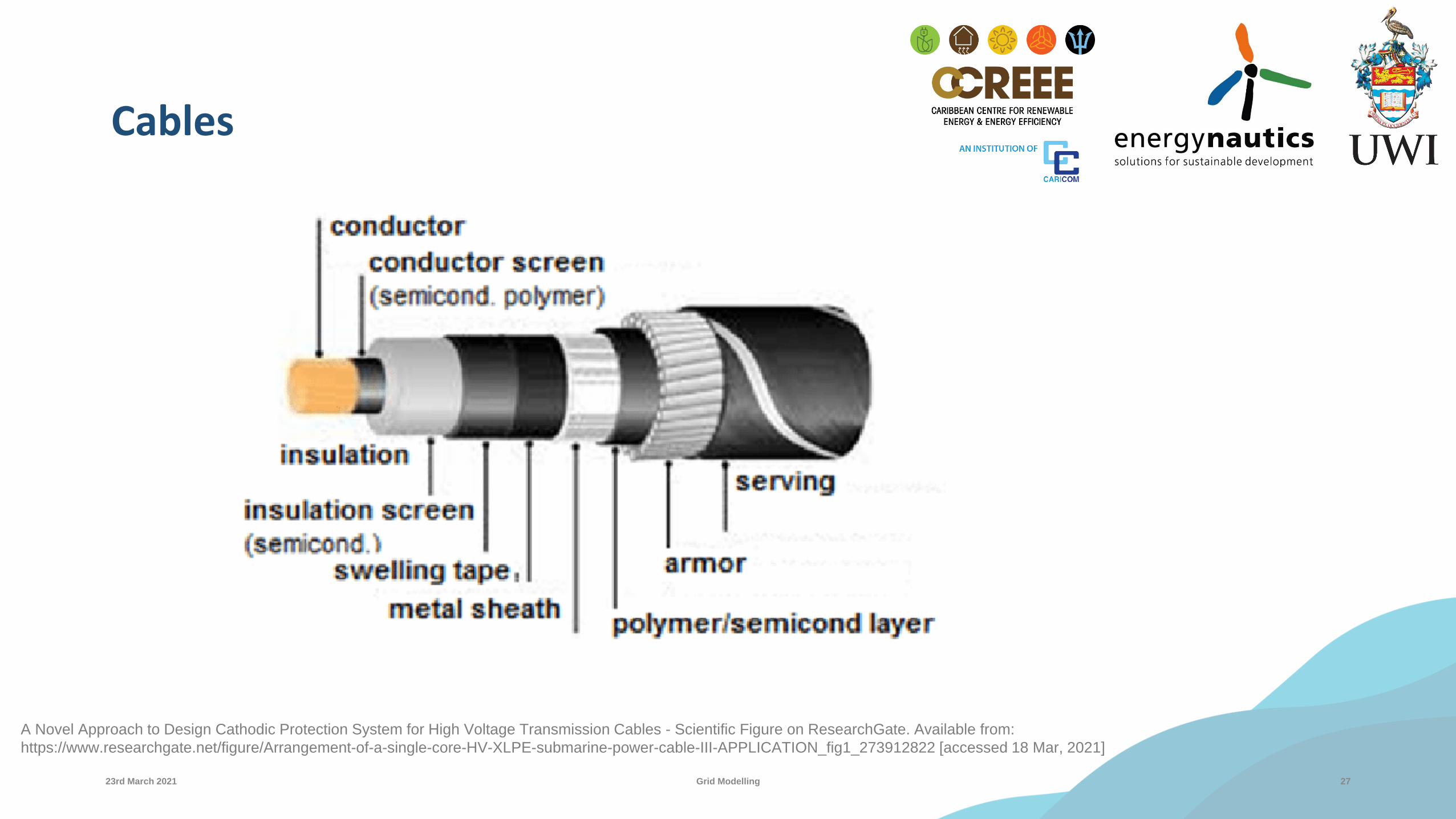
Cables
23rd March 2021 Grid Modelling 27
A Novel Approach to Design Cathodic Protection System for High Voltage Transmission Cables - Scientific Figure on ResearchGate. Available from:
https://www.researchgate.net/figure/Arrangement-of-a-single-core-HV-XLPE-submarine-power-cable-III-APPLICATION_fig1_273912822 [accessed 18 Mar, 2021]

Transmission Towers
23rd March 2021 Grid Modelling 28

Resistance
• Manufacturer gives dc, 50 Hz, 60 Hz
• Affected by:
• Material, stranding, spiraling, temperature and frequency.
23rd March 2021 Grid Modelling 29

Bundle Conductors – GMR and GMD
• GMR = Geometric Mean Radius
GMD = Geometric Mean Distance.
Average distance between centre of
the bundles.
(For capacitance calculations use r)
23rd March 2021 Grid Modelling 30

Transmission Line Parameters
All lines are made up of distributed series inductance and resistance, and shunt capacitance and conductance (per km)
Line parameters: R, L, C, & G
Calculated parameters (Hand equations-assumed totally transposed).
Resistance – tables.
Inductance
Capacitance
=2πε
ln(D/r)F/m line-to-neutralCan
La = 2 x 10⁻⁷ ln (D/r’) H/m per phase
6823rd March 2021 Grid Modelling 31

Transmission Line Models
• Transmission lines are represented by an equivalent circuit with parameters on a per-phase basis
• Voltages are expressed as phase-to-neutral.
• Currents are expressed for one phase.
• The three phase system is reduced to an equivalent single-phase.
• Three types of models
• Depend on the length (and frequency ~ 60 Hz).
• Short, medium, and long length line models.
23rd March 2021 Grid Modelling 32
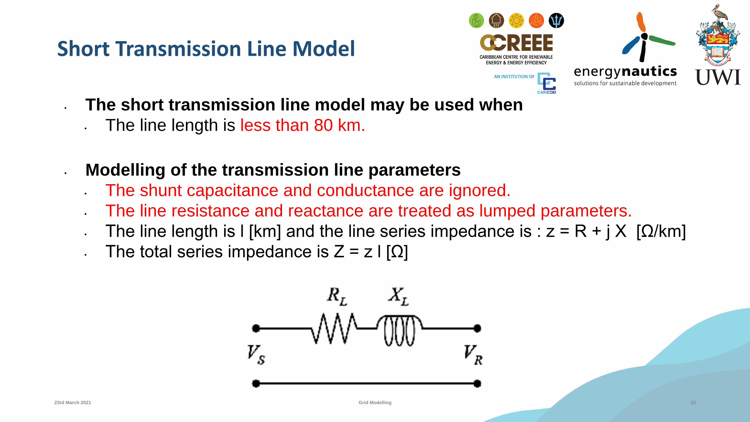
Short Transmission Line Model
• The short transmission line model may be used when
• The line length is less than 80 km.
• Modelling of the transmission line parameters
• The shunt capacitance and conductance are ignored.
• The line resistance and reactance are treated as lumped parameters.
• The line length is l [km] and the line series impedance is : z = R + j X [Ω/km]
• The total series impedance is Z = z l [Ω]
23rd March 2021 Grid Modelling 33
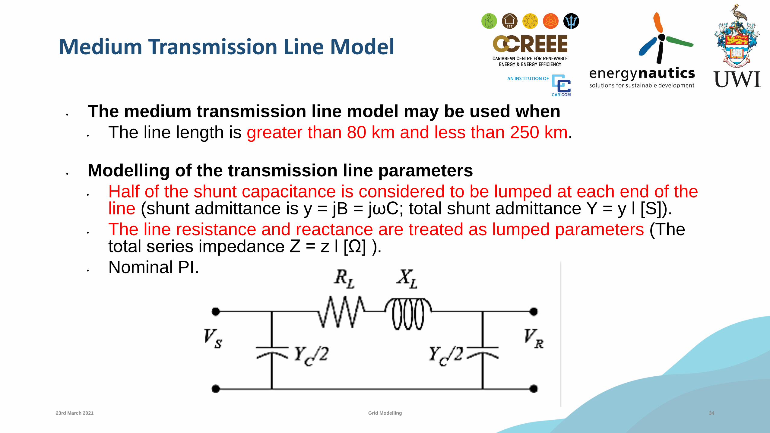
Medium Transmission Line Model
• The medium transmission line model may be used when
• The line length is greater than 80 km and less than 250 km.
• Modelling of the transmission line parameters
• Half of the shunt capacitance is considered to be lumped at each end of the line (shunt admittance is y = jB = jωC; total shunt admittance Y = y l [S]).
• The line resistance and reactance are treated as lumped parameters (The total series impedance Z = z l [Ω] ).
• Nominal PI.
23rd March 2021 Grid Modelling 34

Fault Analysis
23rd March 2021 Grid Modelling 36

Fault Analysis (Short Circuit Analysis)
23rd March 2021 Grid Modelling 37

Fault Analysis
Main Effects (Non-linear)
High Currents
Voltage Level
Heating insulation
Electromechanical stress
Over voltages
Factories
Computers
sags
23rd March 2021 Grid Modelling 38

Fault Analysis
•Control• Protection devices
•Relays, breakers, fuses etc• Other
•Switching schemes, grounding mesh, etc
•Short circuit analysis• Protection coordination
• Selection of breakers
• Selection of current transformers
• Selection of other protective devices
• Contributions from generators and motors
• Calculation of grounding mesh
23rd March 2021 Grid Modelling 39

Symmetrical Components
23rd March 2021 Grid Modelling 40
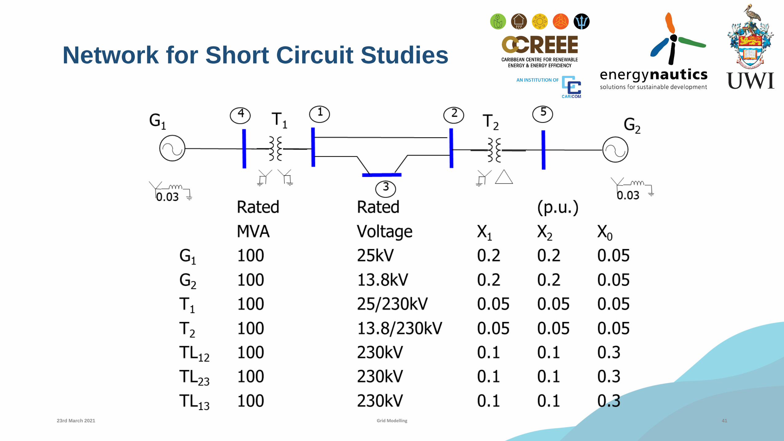
Network for Short Circuit Studies
23rd March 2021 Grid Modelling 41
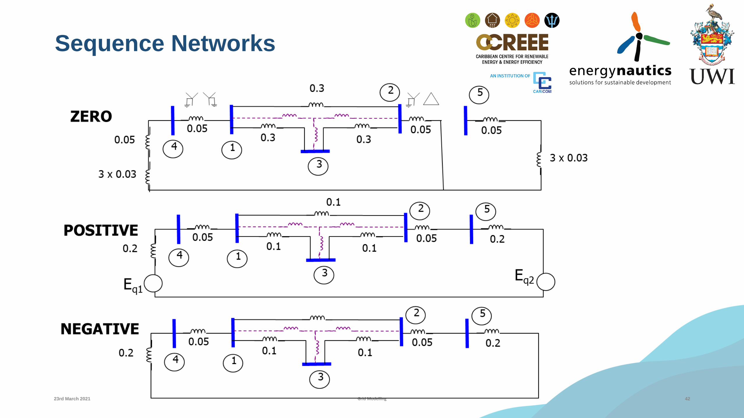
Sequence Networks
23rd March 2021 Grid Modelling 42

A Short BreakBefore we switch presenters
23rd March 2021 Grid Modelling 43

Power Flow
23rd March 2021 Grid Modelling 44
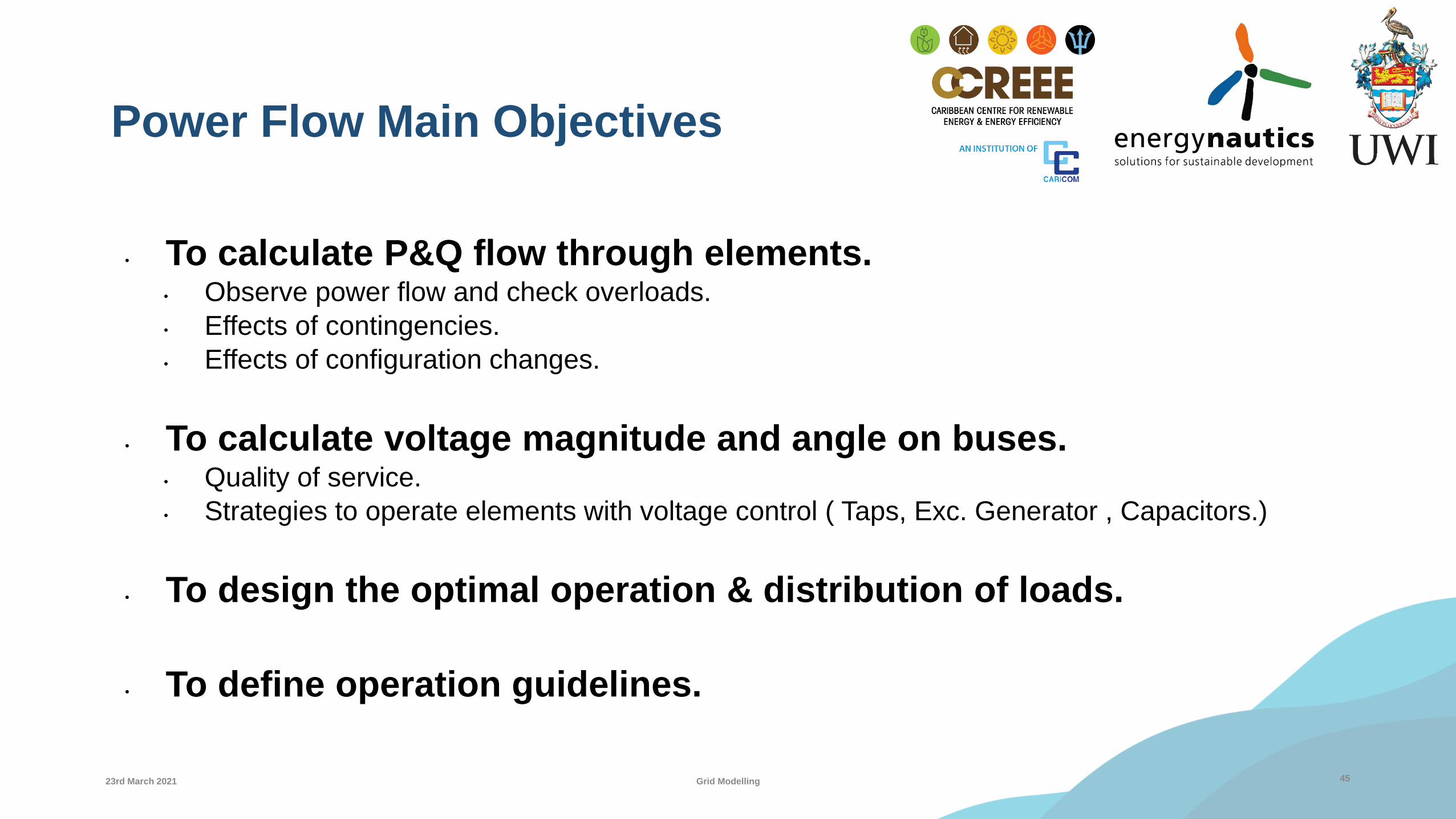
Power Flow Main Objectives
• To calculate P&Q flow through elements.• Observe power flow and check overloads.
• Effects of contingencies.
• Effects of configuration changes.
• To calculate voltage magnitude and angle on buses.• Quality of service.
• Strategies to operate elements with voltage control ( Taps, Exc. Generator , Capacitors.)
• To design the optimal operation & distribution of loads.
• To define operation guidelines.
4523rd March 2021 Grid Modelling

Power Flow
• Operation point of the system.
• Steady State.
• Given conditions of generation, load & configuration: Operation Point
46
Buses (V/Ө)
Branches (P, Q)
Solve Equations (Balance generation and load)
23rd March 2021 Grid Modelling

The Power Flow Problem
Solving the power flow problem amounts to finding the combination of nodal voltage angles and
magnitudes which can simultaneously support the specified real and reactive power injections throughout a network
47
Observation• We have a system of 2n coupled equations in 2n unknowns
• The system of equations is nonlinear
• This means that finding a solution to the power problem is not trivial for realistically-sized power systems with thousands of nodes
• Hence, it is not possible to obtain analytical solutions
Possible only for two-node systems
We will have to resort to specialized iterative numerical methods
23rd March 2021 Grid Modelling

Power Flow
• If load P increases δincreases
• If load Q increases V reduces
• Real power flow
δsending end > δreceiving end
• Reactive power flow
|Vsending end| >|Vreceiving end|
4823rd March 2021 Grid Modelling

Power Flow – Bus Types
• LOAD (PQ)• Given: Pk, Qk
• Unknown: Vk, δk
• Example: Loads, transformer buses
• VOLTAGE CONTROLLED (PV)• Given: Pk, Vk
• Unknown: Qk, δk
• Example: Generation buses, reactive power compensation buses
• SLACK(V δ)• Given: Vk, δk
• Unknown: Pk, Qk
4923rd March 2021 Grid Modelling

Power Flow Tools
• Gauss-Seidel
• Newton Raphson
• Decoupled
• Fast Decoupled
• DC
23rd March 2021 Grid Modelling 50

Gauss-Seidel
Grid Modelling 5123rd March 2021

Simple Iterative MethodsGauss-Seidel method
5223rd March 2021 Grid Modelling

Newton Raphson
Grid Modelling 5323rd March 2021

Newton-Raphson MethodBasic principle for single-variable functions
We recall Taylor’s theorem for functions of a single variable
retaining only the first two terms of the series expansion for x small enough, we can
say
The above is the tangent line approximation of the function f about the point x
5423rd March 2021 Grid Modelling

Newton Raphson - Example
23rd March 2021 Grid Modelling 55
Jacobian Matrix

Newton Raphson - Example
56
Power Systems Analysis ECNG 3012

Newton Raphson - Example
57
Power Systems Analysis ECNG 3012

Newton Raphson - Example
58
Power Systems Analysis ECNG 3012

Newton Raphson - Example
59
Power Systems Analysis ECNG 3012

When Things Go Wrong. . .
• The answer is no!
• So what happens when there is no solution to the power flow problem?
Physically, this means that the system cannot sustain the flow of power, that is the system collapses
The system loading is so high, causing large voltage drops across the network due to reactive power losses mostly
It is synonym with extreme imbalances between network reactive power demand and what can be provided by the sources of reactive power
60
Question
Is it possible for any set of power injections and voltage magnitudes to always yield a valid power flow solution?
23rd March 2021 Grid Modelling

Decoupled Fast Decoupled DC
Faster Power Flow Options
Grid Modelling 6123rd March 2021

Decoupled & Fast Decoupled Power Flow
62
Observation
The Jacobian matrix in the Newton-Raphson power flow solution has the following property
𝐽 =
𝜕𝑃
𝜕𝜃
𝜕𝑃
𝜕𝑉𝜕𝑄
𝜕𝜃
𝜕𝑄
𝜕𝑉
≈
𝜕𝑃
𝜕𝜃0
0𝜕𝑄
𝜕𝑉
where 𝜕𝑃
𝜕𝜃and
𝜕𝑄
𝜕𝑉are square matrices
P – V and Q – θ are weak, hence decoupled
This is a physical property of ac power networks
23rd March 2021 Grid Modelling
Decoupled power flow =>
inverts two smaller-dimension
matrices
Fast-decoupled power flow =>
inverts two smaller-dimension
matrices only once

DC Power Flow
The DC power flow is well-suited for security analysis and planning problems
• Fast because it requires a single iteration and a single matrix inversion
• Line power flow calculations are straightforward
• Unlike full nonlinear and fast decoupled load flows, the DC load flow
Is only an approximation
Always converges
Calculates bus voltage angles only, not bus voltage magnitudes
6323rd March 2021 Grid Modelling
𝜕𝑃
𝜕𝜃

Power System Security
23rd March 2021 Grid Modelling 64

Power System Security
Power system security involves the practices designed to keep the system operating when components fail
“N – 1 security” is a security standard that requires a power system to continue to work satisfactorily following the loss of any one of its N elements.
“N – M security” is a security standard that requires a power system to continue to work satisfactorily following the loss of any M = 1, 2, 3,… of its N elements.
6523rd March 2021 Grid Modelling

Functions of System SecurityContingency analysis
Contingency analysis programs model possible system troubles before they arise
• Defensive approach to the operation of the system.
• Contingency analysis is challenged by the speed of the power flow analysis module used
• Approximate power flow models are used• DC power flow
• Thorough analysis is performed for critical cases only• Programs are based on a model of the power system and
are used to study outage events
6623rd March 2021 Grid Modelling
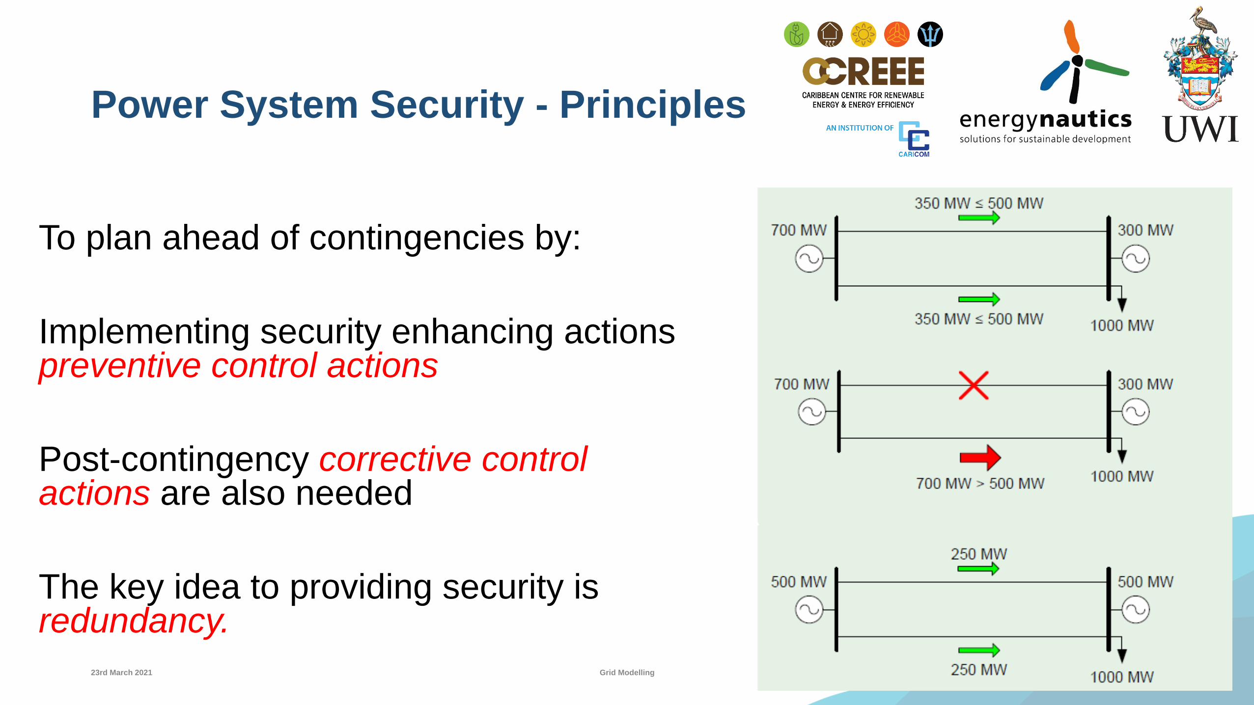
Power System Security - Principles
To plan ahead of contingencies by:
Implementing security enhancing actions preventive control actions
Post-contingency corrective control actions are also needed
The key idea to providing security is redundancy.
6723rd March 2021 Grid Modelling
23rd March 2021

Introduction to Transient Analysis
23rd March 2021 Grid Modelling 68

Power System Stability
• The property of a power system which enables it to remain in a state of operating equilibrium under normal operating conditions and to regain an acceptable state of equilibrium after being subjected to a disturbance.
• Instability may be manifested in many different ways depending on system configuration and operating mode.
6923rd March 2021 Grid Modelling
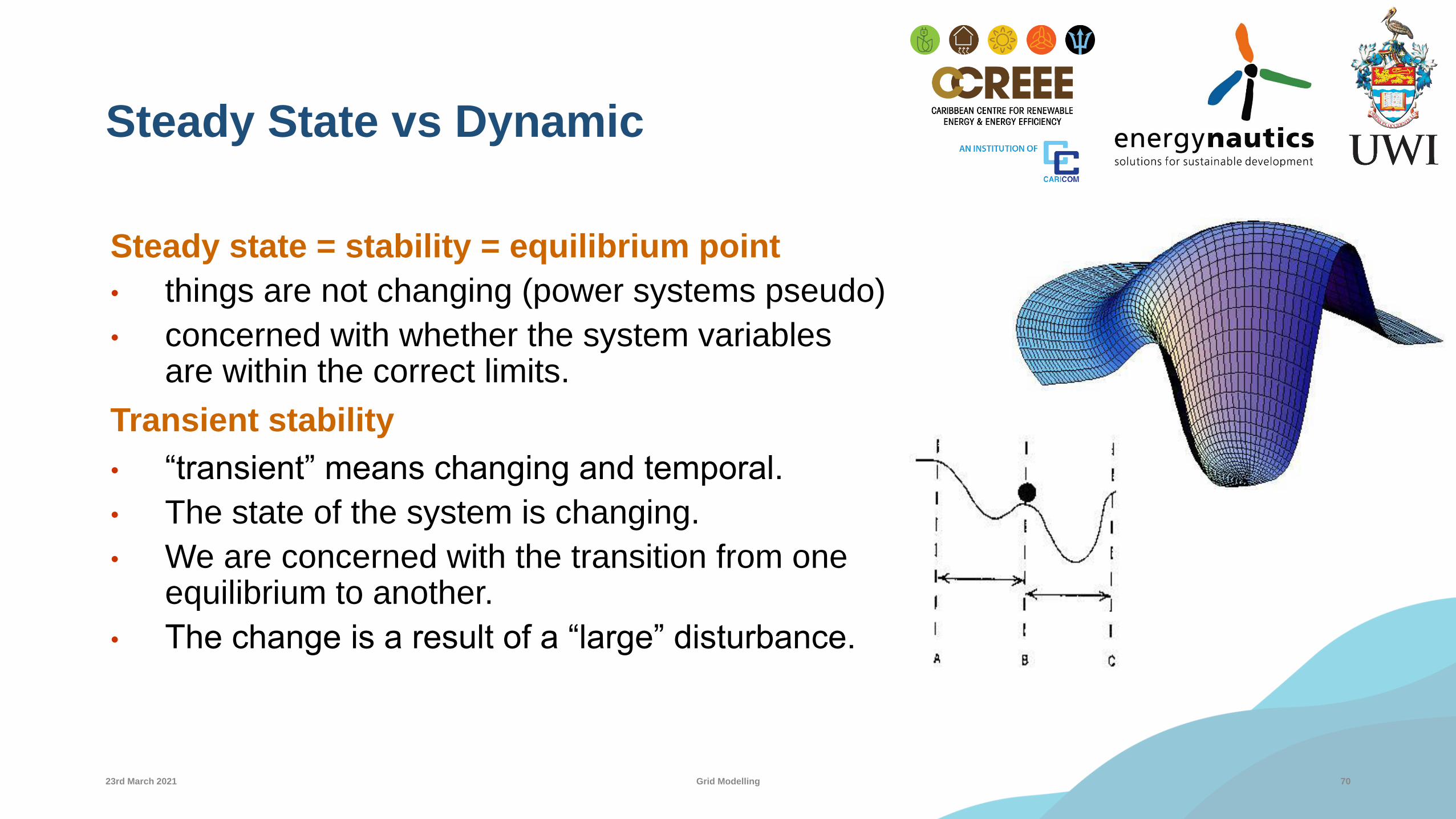
Steady State vs Dynamic
Steady state = stability = equilibrium point
• things are not changing (power systems pseudo)
• concerned with whether the system variables are within the correct limits.
Transient stability
• “transient” means changing and temporal.
• The state of the system is changing.
• We are concerned with the transition from one equilibrium to another.
• The change is a result of a “large” disturbance.
7023rd March 2021 Grid Modelling

Transient Stability
• Transient stability is the ability of a power system to maintain synchronism when subjected to a severe transient disturbance.
• Ability of synchronous machines to move from one steady-state operating point following a disturbance to another steady-state operating point, without losing synchronism.
7123rd March 2021 Grid Modelling
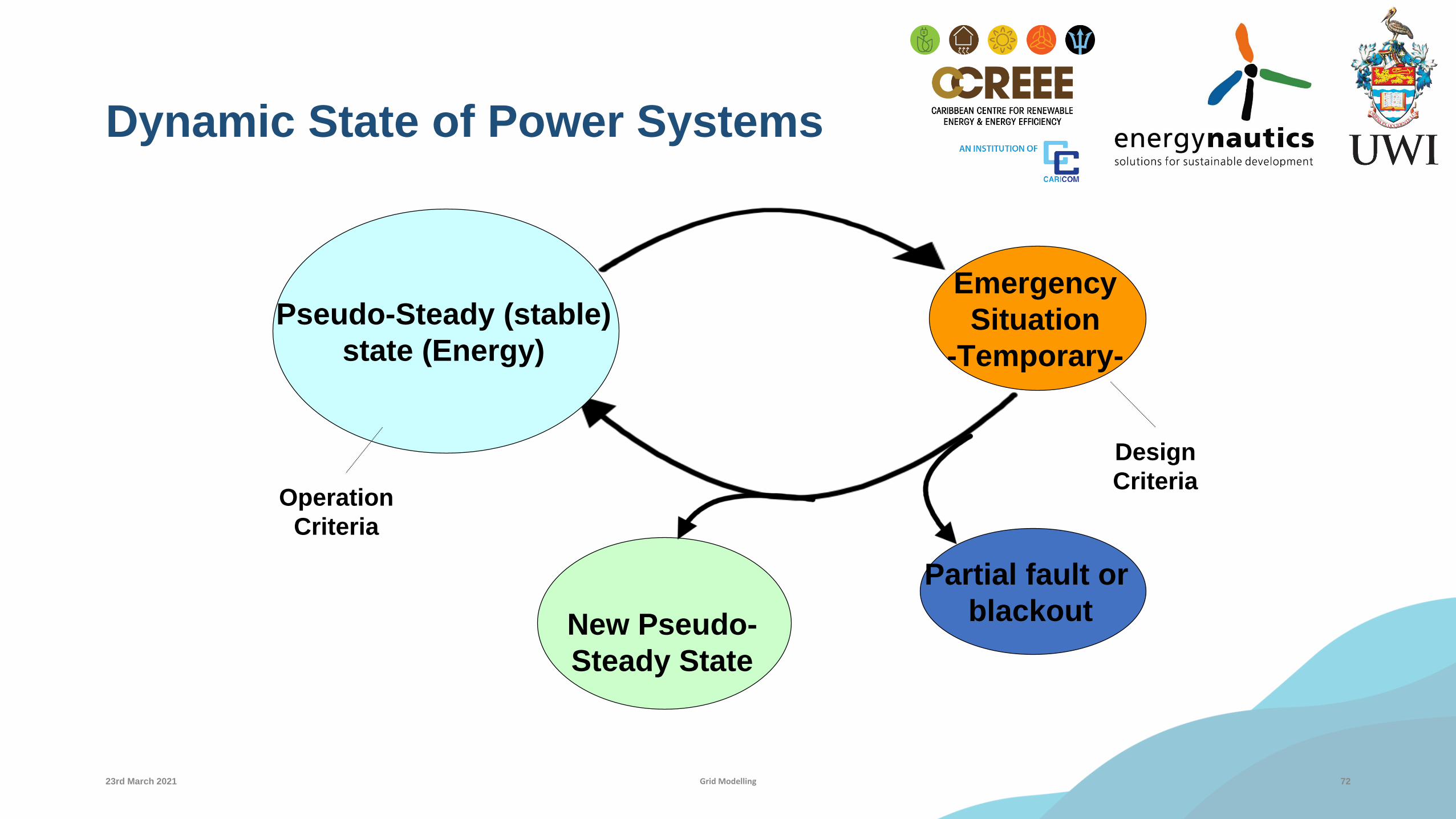
Dynamic State of Power Systems
72
Pseudo-Steady (stable)
state (Energy)
Emergency
Situation
-Temporary-
Partial fault or
blackoutNew Pseudo-
Steady State
Operation
Criteria
Design
Criteria
23rd March 2021 Grid Modelling
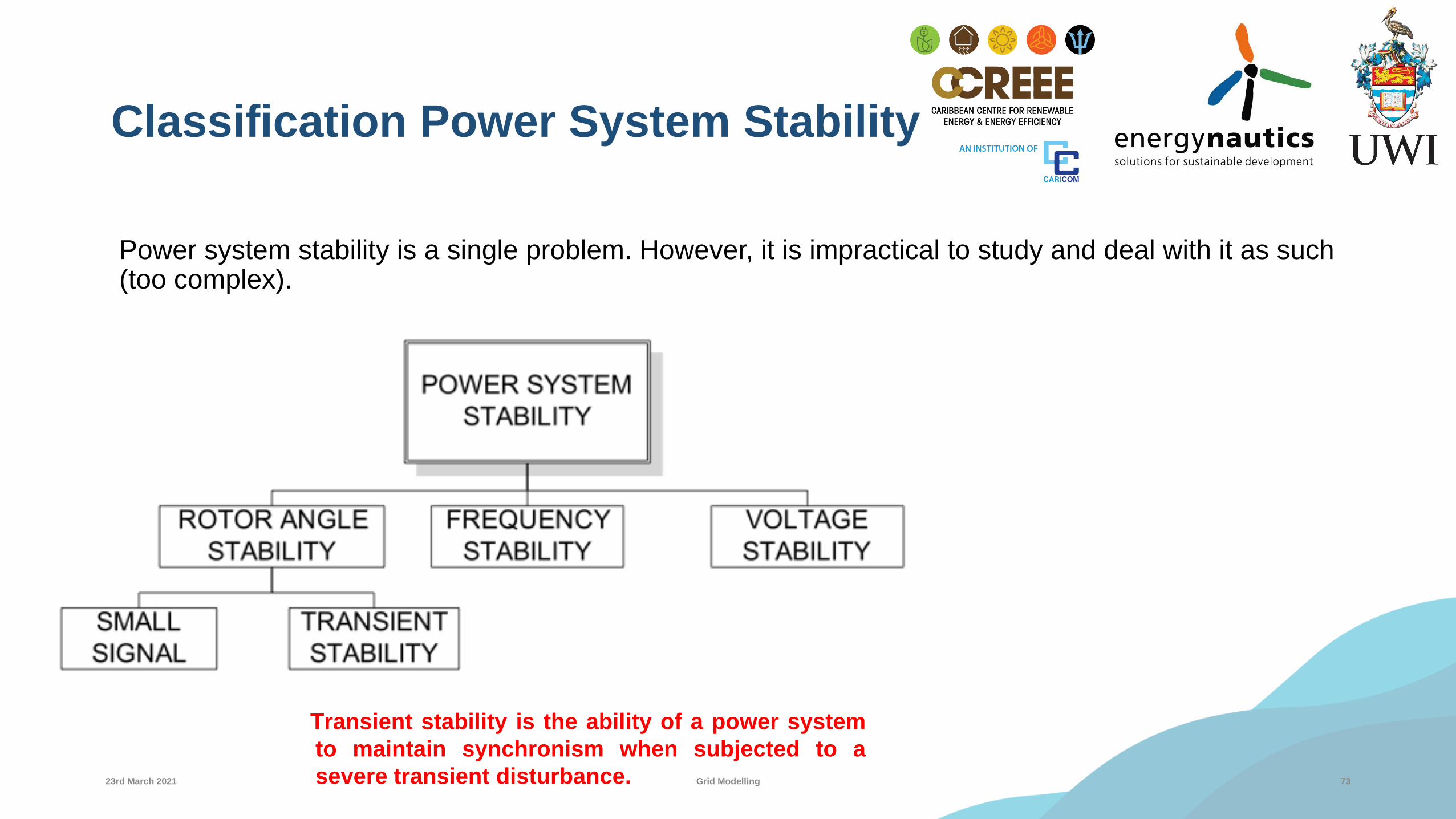
Classification Power System Stability
Power system stability is a single problem. However, it is impractical to study and deal with it as such (too complex).
7323rd March 2021 Grid Modelling
Transient stability is the ability of a power system
to maintain synchronism when subjected to a
severe transient disturbance.
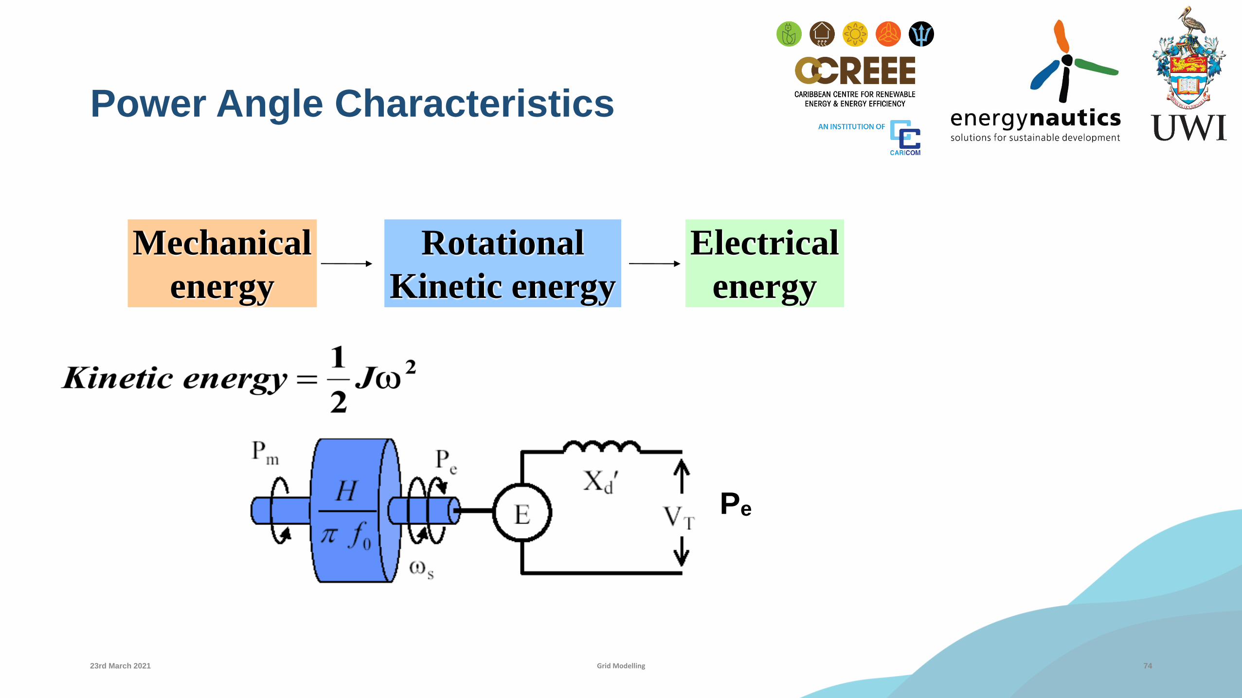
Power Angle Characteristics
74
Mechanical
energy
Rotational
Kinetic energy
Electrical
energy
Pe
23rd March 2021 Grid Modelling

Typical Results
75
0 0.5 1 1.5 2
Simulation time in seconds
0
60
120
180
240
Ge
ne
rato
r a
ng
le in
de
gre
es
clearing at 0.3 seconds
clearing at 0.2 seconds
clearing at 0.1 seconds
23rd March 2021 Grid Modelling

Renewable Energy Integration
23rd March 2021 Grid Modelling 76
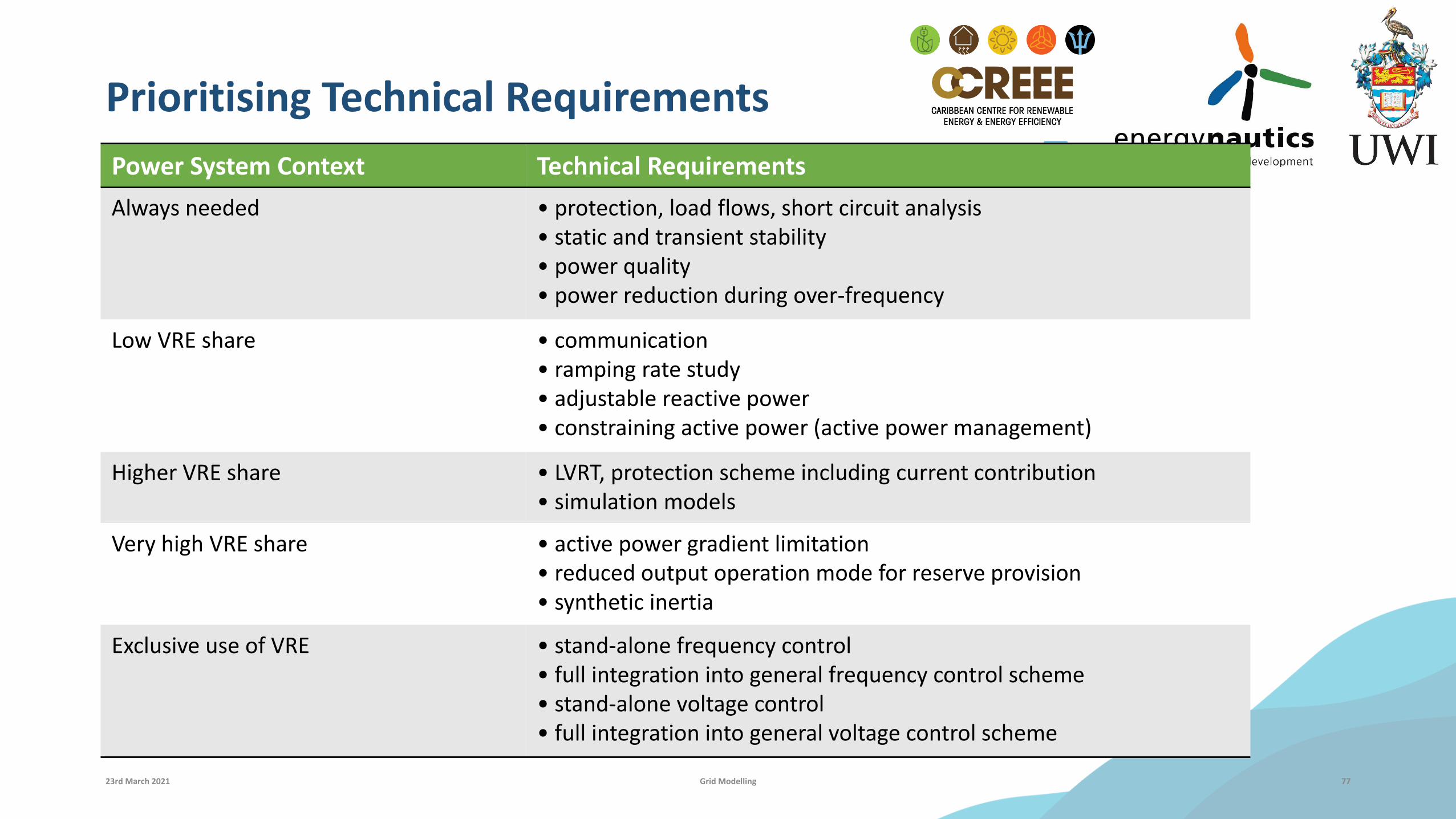
Prioritising Technical Requirements
Power System Context Technical Requirements
Always needed • protection, load flows, short circuit analysis• static and transient stability• power quality• power reduction during over-frequency
Low VRE share • communication• ramping rate study• adjustable reactive power• constraining active power (active power management)
Higher VRE share • LVRT, protection scheme including current contribution• simulation models
Very high VRE share • active power gradient limitation• reduced output operation mode for reserve provision• synthetic inertia
Exclusive use of VRE • stand-alone frequency control• full integration into general frequency control scheme• stand-alone voltage control• full integration into general voltage control scheme
23rd March 2021 Grid Modelling 77

Synthetic Inertia
•Battery energy storage systems (BESS)
•Short-duration storage technologies for primary frequency control.
•Grid-scale batteries, respond at a much faster rate than the mechanical actions of traditional governor controls and blade pitch or wind turbine speed control mechanisms.
•Economic$. http://www.ee.co.za/article/synthetic-inertia-grids-high-renewable-energy-content.html
23rd March 2021 Grid Modelling 78

23rd March 2021 Grid Modelling 79
Power System
Modelling
Contextual Knowledge
Tools & Techniques
Interpret Results
Software
Limitations
Accurate & Complete
Data
• Power Flow
• Contingency
Analysis
• Fault Analysis
• Power
System
Security
• Operational
• Regulatory
• Availability
• Legacy
Equipment
• Frequency and
Accuracy of
Collection
• Compatibility
• Familiarity
• Response as good
as the data used to
produced the model.
• Generation and Load
Profiles
• Expansion Plans

Thank You
23rd March 2021 Grid Modelling 80