tl1 command descriptions - cisco.com 3-1 cisco ons 15454 and cisco ons 15327 tl1 command guide, r4.0...
TRANSCRIPT

Cisco ONS 15454 and CisSeptember 2004
C H A P T E R 3
TL1 Command DescriptionsNote The terms "Unidirectional Path Switched Ring" and "UPSR" may appear in Cisco literature. These terms do not refer to using Cisco ONS 15xxx products in a unidirectional path switched ring configuration. Rather, these terms, as well as "Path Protected Mesh Network" and "PPMN," refer generally to Cisco's path protection feature, which may be used in any topological network configuration. Cisco does not recommend using its path protection feature in any particular topological network configuration.
This chapter provides specific information on TL1 commands and autonomous messages for the Cisco ONS 15454 and the Cisco ONS 15327, Release 4.0, including:
• TL1 commands by category
• TL1 commands by card
• TL1 commands
For information on command components, such as parameters, see Chapter 4, “TL1 Command Components.”
3-1co ONS 15327 TL1 Command Guide, R4.0

Chapter 3 TL1 Command DescriptionsTL1 Commands by Category
3.1 TL1 Commands by CategoryTable 3-1 TL1 Commands by Category
Category Command or Autonomous Message
BLSR DLT-BLSRED-BLSRENT-BLSREX-SW-<OCN_BLSR>REPT EVT RINGRTRV-BLSRRTRV-COND-RINGRTRV-TRC-<OCN_BLSR>
Cross Connections DLT-CRS-<STS_PATH>DLT-CRS-VT1ED-CRS-<STS_PATH>ED-CRS-VT1ENT-CRS-<STS_PATH>ENT-CRS-VT1RTRV-CRSRTRV-CRS-<STS_PATH>RTRV-CRS-VT1
DWDM (ONS 15454) DLT-FFP-CLNTED-CLNTED-DWDMED-FFP-CLNTED-OCHED-TRC-CLNTED-TRC-OCHENT-FFP-CLNTOPR-PROTNSW-CLNTRLS-PROTNSW-CLNTRTRV-CLNTRTRV-DWDMRTRV-FFP-CLNTRTRV-OCHRTRV-PROTNSW-CLNTRTRV-TRC-CLNTRTRV-TRC-OCH
3-2Cisco ONS 15454 and Cisco ONS 15327 TL1 Command Guide, R4.0
September 2004

Chapter 3 TL1 Command DescriptionsTL1 Commands by Category
Environment Alarms and Controls OPR-ACO-ALLOPR-EXT-CONTREPT ALM ENVREPT EVT ENVRLS-EXT-CONTRTRV-ALM-ENVRTRV-ATTR-CONTRTRV-ATTR-ENVRTRV-COND-ENVRTRV-EXT-CONTSET-ATTR-CONTSET-ATTR-ENV
Equipment ALW-SWDX-EQPTALW-SWTOPROTN-EQPTALW-SWTOWKG-EQPTDLT-EQPTED-EQPTENT-EQPTINH-SWDX-EQPTINH-SWTOPROTN-EQPTINH-SWTOWKG-EQPTREPT ALM EQPTREPT EVT EQPTRTRV-ALM-EQPTRTRV-COND-EQPTRTRV-EQPTSW-DX-EQPTSW-TOPROTN-EQPTSW-TOWKG-EQPT
Fault REPT ALM <MOD2ALM>REPT ALM COMREPT ALM RINGREPT EVT <MOD2ALM>REPT EVT COMRTRV-ALM-<MOD2ALM>RTRV-ALM-ALLRTRV-ALM-RINGRTRV-COND-<MOD2ALM>RTRV-COND-ALL
IOS COPY-IOSCFGREPT EVT IOSCFG
Log ALW-MSG-DBCHGINH-MSG-DBCHGREPT DBCHGRTRV-LOG
Network RTRV-NE-IPMAPRTRV-MAP-NETWORK
Table 3-1 TL1 Commands by Category (continued)
Category Command or Autonomous Message
3-3Cisco ONS 15454 and Cisco ONS 15327 TL1 Command Guide, R4.0
September 2004

Chapter 3 TL1 Command DescriptionsTL1 Commands by Category
Performance ALW-PMREPT-ALLINH-PMREPT-ALLINIT-REG-<MOD2>REPT PM <MOD2>RTRV-PM-<MOD2>RTRV-PMMODE-<STS_PATH>RTRV-PMSCHED-<MOD2>RTRV-PMSCHED-ALLRTRV-TH-<MOD2>SCHED-PMREPT-<MOD2>SET-PMMODE-<STS_PATH>SET-TH-<MOD2>
Ports ED-<OCN_TYPE>ED-DS1ED-EC1ED-G1000ED-T1ED-T3INIT-REG-G1000RMV-<MOD2_IO>RST-<MOD2_IO>RTRV-<OCN_TYPE>RTRV-DS1RTRV-EC1RTRV-FSTERTRV-G1000RTRV-GIGERTRV-POSRTRV-T1RTRV-T3
Security ACT-USERALW-MSG-SECUCANCCANC-USERDLT-USER-SECUED-PIDED-USER-SECUENT-USER-SECUINH-MSG-SECUREPT EVT SECUREPT EVT SESSIONRTRV-USER-SECU
Table 3-1 TL1 Commands by Category (continued)
Category Command or Autonomous Message
3-4Cisco ONS 15454 and Cisco ONS 15327 TL1 Command Guide, R4.0
September 2004

Chapter 3 TL1 Command DescriptionsTL1 Commands by Category
SONET Line Protection DLT-FFP-<OCN_TYPE>ED-FFP-<OCN_TYPE>ENT-FFP-<OCN_TYPE>OPR-PROTNSW-<OCN_TYPE>RLS-PROTNSW-<OCN_TYPE>RTRV-FFP-<OCN_TYPE>RTRV-PROTNSW-<OCN_TYPE>
Software Download APPLYCOPY-RFILEREPT EVT FXFR
STS and VT Paths ED-<STS_PATH>ED-VT1RTRV-<STS_PATH>RTRV-PTHTRC-<STS_PATH>RTRV-VT1
Synchronization ED-BITSED-NE-SYNCNED-SYNCNOPR-SYNCNSWREPT ALM BITSREPT ALM SYNCNREPT EVT BITSREPT EVT SYNCNRLS-SYNCNSWRTRV-ALM-BITSRTRV-ALM-SYNCNRTRV-BITSRTRV-COND-BITSRTRV-COND-SYNCNRTRV-NE-SYNCNRTRV-SYNCN
System ALW-MSG-ALLED-DATED-NE-GENINH-MSG-ALLINIT-SYSRTRV-HDRRTRV-INVRTRV-NE-GENRTRV-TODSET-TOD
Test Access CHG-ACCMD-<MOD_TACC>CONN-TACC-<MOD_TACC>DISC-TACCRTRV-TACC
Testing OPR-LPBK-<MOD2>RLS-LPBK-<MOD2>
Table 3-1 TL1 Commands by Category (continued)
Category Command or Autonomous Message
3-5Cisco ONS 15454 and Cisco ONS 15327 TL1 Command Guide, R4.0
September 2004

Chapter 3 TL1 Command DescriptionsTL1 Commands by Card (ONS 15454)
3.2 TL1 Commands by Card (ONS 15454)
UCP DLT-UCP-CCDLT-UCP-IFDLT-UCP-NBRED-UCP-CCED-UCP-IFED-UCP-NBRED-UCP-NODEENT-UCP-CCENT-UCP-IFENT-UCP-NBRREPT ALM UCPREPT EVT UCPRTRV-ALM-UCPRTRV-COND-UCPRTRV-UCP-CCRTRV-UCP-IFRTRV-UCP-NBRRTRV-UCP-NODE
UPSR Switching OPR-PROTNSW-<STS_PATH>OPR-PROTNSW-VT1REPT SWRLS-PROTNSW-<STS_PATH>RLS-PROTNSW-VT1RTRV-PROTNSW-<STS_PATH>RTRV-PROTNSW-VT1
Table 3-2 TL1 Commands by Card (ONS 15454)
G10
00-4
ML1
000-
2M
L100
T-12
EC1
DS1
DS1
ND
S3D
S3N
DS3
ED
S3N
ED
S3XM
OC3
OC3
-8O
C12
OC1
2-4
OC4
8O
C48A
SO
C192
E100
TE1
000T
TCC
XC TCC2
XCVT
XC19
2XC
VXL
AIC
IA
ICM
XPTX
PACT-USER
ALW-MSG-ALL
ALW-MSG-DBCHG
ALW-PMREPT-ALL
ALW-SWDX-EQPT X X X
ALW-SWTOPROTN-EQPT X X X X X X X X
ALW-SWTOWKG-EQPT X X X X X X X X
APPLY X X
CANC
Table 3-1 TL1 Commands by Category (continued)
Category Command or Autonomous Message
3-6Cisco ONS 15454 and Cisco ONS 15327 TL1 Command Guide, R4.0
September 2004

Chapter 3 TL1 Command DescriptionsTL1 Commands by Card (ONS 15454)
CANC-USER
CHG-ACCMD-<CHG_ACCMD> X X X X X X X X X X X X X X X
CONN-TACC-<MOD_TACC> X X X X X X X X X X X X X X X
COPY-IOSCFG X X
COPY-RFILE X X
DISC-TACC X X X X X X X X X X X X X X X
DLT-BLSR X X X X X
DLT-CRS-VT1 X X X X X X X X X X X X
DLT-CRS-<STS_PATH> X X X X X X X X X X X X X X X X X X
DLT-EQPT X X X X X X X X X X X X X X X X X X X X X X X X X X X X X X
DLT-FFP-<OCN_TYPE> X X X X X X X
DLT-FFP-CLNT X X
DLT-UCP-CC X X X X X X X
DLT-UCP-IF
DLT-UCP-NBR
DLT-USER-SECU
ED-BITS X
ED-BLSR X X X X X X X
ED-CRS-<STS_PATH> X X X X X X X X X X X X X X X X X X
ED-CRS-VT1 X X X X X X X X
ED-CLNT X X
ED-DAT
ED-DS1 X
ED-DWDM X X
ED-EC1 X
ED-EQPT X X X X X X X X
ED-FFP-<OCN_TYPE> X X X X X X X
ED-FFP-CLNT X X
ED-G1000 X
ED-NE-GEN X
ED-NE-SYNCN X
ED-OCH X X
ED-PID
ED-SYNCN X X
Table 3-2 TL1 Commands by Card (ONS 15454) (continued)
G10
00-4
ML1
000-
2M
L100
T-12
EC1
DS1
DS1
ND
S3D
S3N
DS3
ED
S3N
ED
S3XM
OC3
OC3
-8O
C12
OC1
2-4
OC4
8O
C48A
SO
C192
E100
TE1
000T
TCC
XC TCC2
XCVT
XC19
2XC
VXL
AIC
IA
ICM
XPTX
P
3-7Cisco ONS 15454 and Cisco ONS 15327 TL1 Command Guide, R4.0
September 2004

Chapter 3 TL1 Command DescriptionsTL1 Commands by Card (ONS 15454)
ED-T1 X X
ED-T3 X X X X X
ED-TRC-CLNT X X
ED-TRC-OCH X X
ED-UCP-CC X X X X X X X
ED-UCP-IF X X X X X X X
ED-UCP-NBR
ED-UCP-NODE
ED-USER-SECU
ED-VT1 X X X X X X X X X X X
ED-<OCN_TYPE> X X X X X X X
ED-<STS_PATH> X X X X X X X X X X X X X X X X X X
ENT-BLSR X X X X X
ENT-CRS-VT1 X X X X X X X X
ENT-CRS-<STS_PATH> X X X X X X X X X X X X X X X X X X
ENT-EQPT X X X X X X X X X X X X X X X X X X X X X X X X X X X X X X
ENT-FFP-<OCN_TYPE> X X X X X X X
ENT-FFP-CLNT X X
ENT-UCP-CC X X X X X X X
ENT-UCP IF X X X X X X X
ENT-UCP-NBR
ENT-USER-SECU
EX-SW-<OCN_BLSR> X X X X X X
INH-MSG-ALL
INH-MSG-DBCHG
INH-MSG-SECU X X
ING-PMREPT-ALL
INH-SWDX-EQPT X X X
INH-SWTOPROTN-EQPT X X X X X X X X
INH-SWTOWKG-EQPT X X X X X X X X
INIT-REG-<MOD2> X X X X X X X X X X X X X X X
INIT-REG-G1000 X
INIT-REG-CLNT X X
INIT-SYS X X X X X X X X X X X X X X X X X X X X X X X X X X X X X X
Table 3-2 TL1 Commands by Card (ONS 15454) (continued)
G10
00-4
ML1
000-
2M
L100
T-12
EC1
DS1
DS1
ND
S3D
S3N
DS3
ED
S3N
ED
S3XM
OC3
OC3
-8O
C12
OC1
2-4
OC4
8O
C48A
SO
C192
E100
TE1
000T
TCC
XC TCC2
XCVT
XC19
2XC
VXL
AIC
IA
ICM
XPTX
P
3-8Cisco ONS 15454 and Cisco ONS 15327 TL1 Command Guide, R4.0
September 2004

Chapter 3 TL1 Command DescriptionsTL1 Commands by Card (ONS 15454)
OPR-ACO-ALL X X
OPR-EXT-CONT X X
OPR-LPBK-<MOD2> X X X X X X X X X X X X X X X X X X
OPR-PROTNSW-VT1 X X X X X X X
OPR-PROTNSW-<OCN_TYPE> X X X X X X X
OPR-PROTNSW-<STS_PATH> X X X X X X X
OPR-PROTNSW-CLNT X X
OPR-SYNCNSW X X X X X X X X
REPT ALM BITS X
REPT ALM COM
REPT ALM ENV X X
REPT ALM EQPT X X X X X X X X X X X X X X X X X X X X X X X X X X X X X X
REPT ALM RING X X X X X
REPT ALM SYNCN X X X X X X X X
REPT ALM <MOD2ALM> X X X X X X X X X X X X X X X X X X X X X X X X X X X X X X
REPT ALM UCP
REPT DBCHG X X X X X X X X X X X X X X X X X X X X X X X X X X X X X X
REPT EVT BITS X
REPT EVT COM
REPT EVT ENV X X
REPT EVT FXFR X X
REPT EVT EQPT X X X X X X X X X X X X X X X X X X X X X X X X X X X X X X
REPT EVT IOSCFG X X
REPT EVT RING X X X X X
REPT EVT SECU
REPT EVT SESSION X X
REPT EVT SYNCN X X X X X X X X
REPT EVT <MOD2ALM> X X X X X X X X X X X X X X X X X X X X X X X X X X X X X X
REPT EVT UCP
REPT PM <MOD2> X X X X X X X X X X X X X X X X X
REPT SW X X X
RLS-EXT-CONT X X
RLS-LPBK-<MOD2> X X X X X X X X X X X X X X X X
RLS-PROTNSW-CLNT X X
Table 3-2 TL1 Commands by Card (ONS 15454) (continued)
G10
00-4
ML1
000-
2M
L100
T-12
EC1
DS1
DS1
ND
S3D
S3N
DS3
ED
S3N
ED
S3XM
OC3
OC3
-8O
C12
OC1
2-4
OC4
8O
C48A
SO
C192
E100
TE1
000T
TCC
XC TCC2
XCVT
XC19
2XC
VXL
AIC
IA
ICM
XPTX
P
3-9Cisco ONS 15454 and Cisco ONS 15327 TL1 Command Guide, R4.0
September 2004

Chapter 3 TL1 Command DescriptionsTL1 Commands by Card (ONS 15454)
RLS-PROTNSW-VT1 X X X X X X X
RLS-PROTNSW-<OCN_TYPE> X X X X X X X
RLS-PROTNSW-<STS_PATH> X X X X X X X
RLS-SYNCNSW X X X X X X X X
RMV-<MOD2_IO> X X X X X X X X X X X X X X X X X X
RST-<MOD2_IO> X X X X X X X X X X X X X X X X X X
RTRV-ALM-ALL X X X X X X X X X X X X X X X X X X X X X X X X X X X X X X
RTRV-ALM-BITS X
RTRV-ALM-ENV X X
RTRV-ALM-EQPT X X X X X X X X X X X X X X X X X X X X X X X X X X X X X X
RTRV-ALM-RING X X X X X
RTRV-ALM-SYNCN X X X X X X X X
RTRV-ALM-<MOD2ALM> X X X X X X X X X X X X X X X X X X X X X X X X X X X X X X
RTRV-ALM-UCP
RTRV-ATTR-CONT X X
RTRV-ATTR-ENV X X
RTRV-BITS X
RTRV-BLSR X X X X X
RTRV-CKT-ORIG
RTRV-CKT-TERM
RTRV-CLNT X X
RTRV-COND-ALL X X X X X X X X X X X X X X X X X X X X X X X X X X X X X X
RTRV-COND-BITS X
RTRV-COND-ENV X X
RTRV-COND-EQPT X X X X X X X X X X X X X X X X X X X X X X X X X X X X X X
RTRV-COND-SYNCN X
RTRV-COND-<MOD2ALM> X X X X X X X X X X X X X X X X X X X X X X X X X X X X X X
RTRV-COND-RING X X X X X
RTRV-COND-UCP
RTRV-CRS X X X X X X X X X X X X X X X X X X
RTRV-CRS-VT1 X X X X X X X X X X X
RTRV-CRS-<STS_PATH> X X X X X X X X X X X X X X X X X X
RTRV-DWMD X X
RTRV-EC1 X
Table 3-2 TL1 Commands by Card (ONS 15454) (continued)
G10
00-4
ML1
000-
2M
L100
T-12
EC1
DS1
DS1
ND
S3D
S3N
DS3
ED
S3N
ED
S3XM
OC3
OC3
-8O
C12
OC1
2-4
OC4
8O
C48A
SO
C192
E100
TE1
000T
TCC
XC TCC2
XCVT
XC19
2XC
VXL
AIC
IA
ICM
XPTX
P
3-10Cisco ONS 15454 and Cisco ONS 15327 TL1 Command Guide, R4.0
September 2004

Chapter 3 TL1 Command DescriptionsTL1 Commands by Card (ONS 15454)
RTRV-DS1 X
RTRV-EQPT X X X X X X X X X X X X X X X X X X X X X X X X X X X X X X
RTRV-EXT-CONT X X
RTRV-FFP-CLNT
RTRV-FFP-<OCN_TYPE> X X X X X X X
RTRV-FSTE X X
RTRV-G1000 X
RTRV-GIGE X X
RTRV-HDR
RTRV-INV X X X X X X X X X X X X X X X X X X X X X X X X X X X X X X
RTRV-LOG
RTRV-MAP-NETWORK
RTRV-NE-GEN X
RTRV-NE-IPMAP X X X X X X X
RTRV-NE-SYNCN X
RTRV-OCH X X
RTRV-PM-<MOD2> X X X X X X X X X X X X X X X X X
RTRV-PMMODE-<STS_PATH> X X X X X X X X X X X X X X X
RTRV-PMSCHED-<MOD2> X X X X X X X X X X X X X X X X X
RTRV-PMSCHED-ALL X X
RTRV-POS X X
RTRV-PROTNSW-<OCN_TYPE> X X X X X X X
RTRV-PROTNSW-<STS_PATH> X X X X X X X X X X
RTRV-PROTNSW-CLNT X X
RTRV-PROTNSW-VT1 X X X X X X X
RTRV-PTHTRC-<STS_PATH> X X X X X X X X X X X X X X X
RTRV-SYNCN X X
RTRV-TACC X X X X X X X X X X X X X X X
RTRV-T1 X X
RTRV-T3 X X X X
RTRV-TH-<MOD2> X X X X X X X X X X X X X X X X X
RTRV-TOD
RTRV-TRC-<OCN_BLSR> X X X X X
RTRV-TRC-CLNT X X
Table 3-2 TL1 Commands by Card (ONS 15454) (continued)
G10
00-4
ML1
000-
2M
L100
T-12
EC1
DS1
DS1
ND
S3D
S3N
DS3
ED
S3N
ED
S3XM
OC3
OC3
-8O
C12
OC1
2-4
OC4
8O
C48A
SO
C192
E100
TE1
000T
TCC
XC TCC2
XCVT
XC19
2XC
VXL
AIC
IA
ICM
XPTX
P
3-11Cisco ONS 15454 and Cisco ONS 15327 TL1 Command Guide, R4.0
September 2004

Chapter 3 TL1 Command DescriptionsTL1 Commands by Card (ONS 15327)
3.3 TL1 Commands by Card (ONS 15327)
RTRV-TRC-OCH X X
RTRV-VT1 X X X X X X X X X X
RTRV-<OCN_TYPE> X X X X X X X X
RTRV-<STS_PATH> X X X X X X X X X X X X X X X X X X
RTRV-UCP-CC X X X X X X X X
RTRV-UCP-IF X X X X X X X X
RTRV-UCP-NBR
RTRV-UCP-NODE
RTRV-USER-SECU
SCHED-PMREPT-<MOD2> X X X X X X X X X X X X X X X X X
SET-ATTR-CONT X X
SET-ATTR-ENV X X
SET-PMMODE-<STS_PATH> X X X X X X X X X X X X X X X
SET-TH-<MOD2> X X X X X X X X X X X X X X X X X
SET-TOD
SW-DX-EQPT X X X
SW-TOPROTN-EQPT X X X X X X X X
SW-TOWKG-EQPT X X X X X X X X
Table 3-3 TL1 Commands by Card (ONS 15327)
XTC/
DS1
XTC/
DS3
OC3
OC1
2
OC4
8
E100
T
E100
0T
XTC
G10
00-2
XTC/
XCVT
XTC/
AIC
ACT-USER
ALW-MSG-ALL
ALW-MSG-DBCHG
ALW-PMREPT-ALL
ALW-SWDX-EQPT
ALW-SWTOPROTN-EQPT
ALW-SWTOWKG-EQPT
APPLY X
Table 3-2 TL1 Commands by Card (ONS 15454) (continued)
G10
00-4
ML1
000-
2M
L100
T-12
EC1
DS1
DS1
ND
S3D
S3N
DS3
ED
S3N
ED
S3XM
OC3
OC3
-8O
C12
OC1
2-4
OC4
8O
C48A
SO
C192
E100
TE1
000T
TCC
XC TCC2
XCVT
XC19
2XC
VXL
AIC
IA
ICM
XPTX
P
3-12Cisco ONS 15454 and Cisco ONS 15327 TL1 Command Guide, R4.0
September 2004

Chapter 3 TL1 Command DescriptionsTL1 Commands by Card (ONS 15327)
CANC
CANC-USER
CHG-ACCMD-<CHG_ACCMD> X X X X X
CONN-TACC-<MOD_TACC> X X X X X
COPY-IOSCFG
COPY-RFILE X
DISC-TACC X X X X X
DLT-BLSR X X
DLT-CRS-VT1 X X X
DLT-CRS-<STS_PATH> X X X X X
DLT-EQPT X X X X X X X
DLT-FFP-<OCN_TYPE> X X X
DLT-USER-SECU
ED-BITS X
ED-BLSR X X
ED-CRS-<STS_PATH> X X X X X X
ED-CRS-VT1 X X X
ED-DAT
ED-DS1
ED-EC1
ED-EQPT X X
ED-FFP-<OCN_TYPE> X X X
ED-G1000 X
ED-NE-GEN X
ED-NE-SYNCN X
ED-PID
ED-SYNCN X
ED-T1 X
ED-T3 X
ED-USER-SECU
ED-VT1 X X X X
ED-<OCN_TYPE> X X X
ED-<STS_PATH> X X X X X X
ENT-BLSR X X
Table 3-3 TL1 Commands by Card (ONS 15327) (continued)
XTC/
DS1
XTC/
DS3
OC3
OC1
2
OC4
8
E100
T
E100
0T
XTC
G10
00-2
XTC/
XCVT
XTC/
AIC
3-13Cisco ONS 15454 and Cisco ONS 15327 TL1 Command Guide, R4.0
September 2004

Chapter 3 TL1 Command DescriptionsTL1 Commands by Card (ONS 15327)
ENT-CRS-VT1 X X X
ENT-CRS-<STS_PATH> X X X X X X
ENT-EQPT X X X X X X X X X X X
ENT-FFP-<OCN_TYPE> X X X
ENT-USER-SECU
EX-SW-<OCN_BLSR> X X
INH-MSG-ALL
INH-MSG-DBCHG
INH-MSG-SECU X
INH-PMREPT-ALL
INH-SWDX-EQPT X
INH-SWTOPROTN-EQPT X X
INH-SWTOWKG-EQPT X X
INIT-REG-<MOD2> X X X X X
INIT-REG-G1000 X
INIT-SYS X X X X X X X X X X X
OPR-ACO-ALL X
OPR-EXT-CONT X
OPR-LPBK-<MOD2> X X X X X X
OPR-PROTNSW-VT1 X X X
OPR-PROTNSW-<OCN_TYPE> X X X
OPR-PROTNSW-<STS_PATH> X X X
OPR-SYNCNSW X X X X
REPT ALM BITS X
REPT ALM COM
REPT ALM ENV X
REPT ALM EQPT X X X X X X X X X X X
REPT ALM RING X X
REPT ALM SYNCN X X X X
REP ALM <MOD2ALM> X X X X X X X X X X X
REPT DBCHG X
REPT EVT BITS X
REPT EVT COM
REPT EVT ENV X
Table 3-3 TL1 Commands by Card (ONS 15327) (continued)
XTC/
DS1
XTC/
DS3
OC3
OC1
2
OC4
8
E100
T
E100
0T
XTC
G10
00-2
XTC/
XCVT
XTC/
AIC
3-14Cisco ONS 15454 and Cisco ONS 15327 TL1 Command Guide, R4.0
September 2004

Chapter 3 TL1 Command DescriptionsTL1 Commands by Card (ONS 15327)
REPT EVT EQPT X X X X X X X X X X X
REPT EVT FXFR X
REPT EVT RING X X
REPT EVT SECU
REPT EVT SESSION X
REPT EVT SYNCN X X X X
REPT EVT <MOD2ALM> X X X X X X X X X X X
REPT PM <MOD2> X X X X X X
REPT SW X
RLS-EXT-CONT X
RLS-LPBK-<MOD2> X X X X X X
RLS-PROTNSW-VT1 X X X
RLS-PROTNSW-<OCN_TYPE> X X X
RLS-PROTNSW-<STS_PATH> X X X
RLS-SYNCNSW X X X X
RMV-<MOD2_IO> X X X X X X
RST-<MOD2_IO> X X X X X X
RTRV-ALM-ALL X X X X X X X X X X X
RTRV-ALM-BITS X
RTRV-ALM-ENV X
RTRV-ALM-EQPT X X X X X X X X X X X
RTRV-ALM-RING
RTRV-ALM-SYNCN X X X X
RTRV-ALM-<MOD2ALM> X X X X X X X X X X X
RTRV-ATTR-CONT X
RTRV-ATTR-ENV X
RTRV-BITS X
RTRV-BLSR X X
RTRV-COND-ALL X X X X X X X X X X X
RTRV-COND-BITS X
RTRV-COND-ENV X
RTRV-COND-EQPT X X X X X X X X X X X
RTRV-COND-RING
RTRV-COND-SYNCN X
Table 3-3 TL1 Commands by Card (ONS 15327) (continued)
XTC/
DS1
XTC/
DS3
OC3
OC1
2
OC4
8
E100
T
E100
0T
XTC
G10
00-2
XTC/
XCVT
XTC/
AIC
3-15Cisco ONS 15454 and Cisco ONS 15327 TL1 Command Guide, R4.0
September 2004

Chapter 3 TL1 Command DescriptionsTL1 Commands by Card (ONS 15327)
RTRV-COND-<MOD2ALM> X X X X X X X X X X X
RTRV-CRS X X X X X X
RTRV-CRS-VT1 X X X X
RTRV-CRS-<STS_PATH> X X X X X X
RTRV-EC1
RTRV-DS1
RTRV-EQPT X X X X X X X X X X X
RTRV-EXT-CONT X
RTRV-FFP-<OCN_TYPE> X X X
RTRV-G1000 X
RTRV-HDR
RTRV-INV X X X X X X X X X X X
RTRV-LOG
RTRV-MAP-NETWORK
RTRV-NE-GEN X
RTRV-NE-IPMAP X X X
RTRV-NE-SYNCN X
RTRV-PM-<MOD2> X X X X X
RTRV-PMMODE-<STS_PATH> X X X X
RTRV-PMSCHED-ALL X X X X X
RTRV-PMSCHED-<MOD2> X X X X X
RTRV-PROTNSW-VT1 X X X
RTRV-PROTNSW-<OCN_TYPE> X X X
RTRV-PROTNSW-<STS_PATH> X X X
RTRV-PTHTRC-<STS_PATH> X X X X
RTRV-SYNCN X
RTRV-T1 X
RTRV-T3 X
RTRV-TACC X X X X X
RTRV-TH-<MOD2> X X X X X
RTRV-TOD
RTRV-TRC-<OCN_BLSR> X X
RTRV-USER-SECU
RTRV-VT1 X X X X
Table 3-3 TL1 Commands by Card (ONS 15327) (continued)
XTC/
DS1
XTC/
DS3
OC3
OC1
2
OC4
8
E100
T
E100
0T
XTC
G10
00-2
XTC/
XCVT
XTC/
AIC
3-16Cisco ONS 15454 and Cisco ONS 15327 TL1 Command Guide, R4.0
September 2004

Chapter 3 TL1 Command DescriptionsTL1 Commands by Card (ONS 15327)
RTRV-<OCN_TYPE> X X X
RTRV-<STS_PATH> X X X X X X
SCHED-PMREPT-<MOD2>
SET-ATTR-CONT X
SET-ATTR-ENV X
SET-PMMODE-<STS_PATH> X X X X X
SET-TH-<MOD2> X X X X X
SET-TOD
SW-DX-EQPT X
SW-TOPROTN-EQPT X X
SW-TOWKG-EQPT X X
Table 3-3 TL1 Commands by Card (ONS 15327) (continued)
XTC/
DS1
XTC/
DS3
OC3
OC1
2
OC4
8
E100
T
E100
0T
XTC
G10
00-2
XTC/
XCVT
XTC/
AIC
3-17Cisco ONS 15454 and Cisco ONS 15327 TL1 Command Guide, R4.0
September 2004
Chapter 3 TL1 Command DescriptionsTL1 Commands
3.4 TL1 CommandsThe commands and autonomous messages used for ONS 15454 and ONS 15327 are described in detail in this section and are listed alphabetically according to the first alpha character of the command string.
Each TL1 command must be less than or equal to 255 characters. Any command larger than 255 characters must be split into multiple commands. For example, if you use the ED-<STS_PATH> command to edit the J1 EXPTRC/TRC message, path protection configuration attributes, and TACC attributes and the command exceeds 255 characters the command will not be processed. You must use multiple ED-<STS_PATH> commands instead.
Note The CTAG of any TL1 line mode command is a mandatory field in this TL1 release.
Note The AID definitions provided are supersets of the actual AID definitions.
Note TL1 commands that are entered incorrectly are not completed.
Note Starting with release 3.3 (R3.3), all TL1 commands will return the DENY error code without any additional error messages prior to a successful TL1 login (i.e., prior to a successful ACT-USER command). Releases earlier than R3.3 either return different error codes; for example, PLNA and IICT and also additional error messages; for example, Login Not Active.
3.4.1 ACT-USER: Activate UserThis command set-ups a session with the Network Element (NE).
Notes:
1. Passwords are masked for the following security commands: ACT-USER, ED-PID, ENT-USER-SECU and ED-USER-SECU. Access to a TL1 session via any means will have the password masked. The CTC Request History and Message Log will also show the masked commands. When a password-masked command is re-issued by double-clicking the command from CTC Request History, the password will still be masked in the CTC Request History and Message Log. The actual password that was previously issued will be sent to the NE. To use a former command as a template only, single-click the command in CTC Request History. The command will be placed in the Command Request text box, where you can edit the appropriate fields prior to re-issuing it.
2. In this release, the ACT-USER command does not return the date and time of the last session established by the UID or the number of unsuccessful session attempts since the last session.
3. This command is backwards compatible with userids and passwords from ONS 15454 2.X software versions according to the following rules:
ACT-USER:[TID]:[STRING]:CTAG::[STRING]
a. The syntax of the userid (first [STRING]) and the password (second [STRING]) are not checked.
3-18Cisco ONS 15454 and Cisco ONS 15327 TL1 Command Guide, R4.0
September 2004

Chapter 3 TL1 Command DescriptionsTL1 Commands
b. Invalid syntax for both the userid and password is permitted, but the user can only log in if the userid/password match what is in the database.
c. The userid and password cannot exceed 10 characters.
4. For the ACT-USER command, it is required that no error code be transmitted except to convey that the login is granted or denied. Per TR-835, Appendix A, Section A.2:
“... the error codes corresponding to ACT ... do not apply to the ACT-USER command because this command requires that no error code be provided to the session request except to indicate that it has been denied. Before a session is established, a specific error code may reveal clues to an intruder attempting unauthorized entry.”
Section ACT-USER Description
Category Security
Security N/A
Related Messages
CANCCANC-USERDLT-USER-SECUED-PIDED-USER-SECUENT-USER-SECUREPT EVT SECURTRV-USER-SECU
Input Format ACT-USER:[<TID>]:<UID>:<CTAG>::<PID>;
where:
• <UID> is the user identifier; <UID> is any combination of up to 10 alphanumeric characters. <UID> is a string and must not be null
• <PID> is the user password; <PID> is any combination of up to 10 alphanumeric characters. <PID> is a string and must not be null
Note CTC allows <UID> and <PID> of up to 20 characters. The 20 character CTC-entered <UID> and <PID> are not valid TL1 <UID> and <PID>
Input Example ACT-USER:PETALUMA:TERRI:100::MYPASSWD;
Errors Errors are listed in Table 7-30 on page 7-20.
3-19Cisco ONS 15454 and Cisco ONS 15327 TL1 Command Guide, R4.0
September 2004
Chapter 3 TL1 Command DescriptionsTL1 Commands
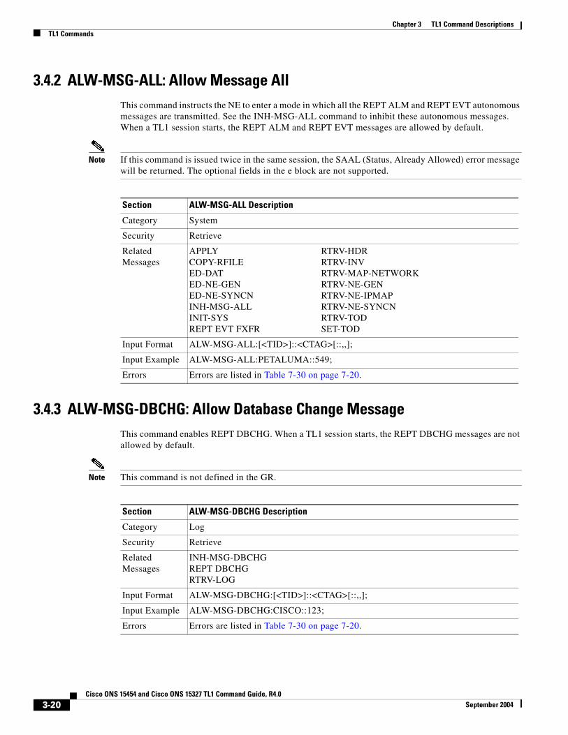
3.4.2 ALW-MSG-ALL: Allow Message AllThis command instructs the NE to enter a mode in which all the REPT ALM and REPT EVT autonomous messages are transmitted. See the INH-MSG-ALL command to inhibit these autonomous messages. When a TL1 session starts, the REPT ALM and REPT EVT messages are allowed by default.
Note If this command is issued twice in the same session, the SAAL (Status, Already Allowed) error message will be returned. The optional fields in the e block are not supported.
3.4.3 ALW-MSG-DBCHG: Allow Database Change MessageThis command enables REPT DBCHG. When a TL1 session starts, the REPT DBCHG messages are not allowed by default.
Note This command is not defined in the GR.
Section ALW-MSG-ALL Description
Category System
Security Retrieve
Related Messages
APPLY RTRV-HDRCOPY-RFILE RTRV-INVED-DAT RTRV-MAP-NETWORKED-NE-GEN RTRV-NE-GENED-NE-SYNCN RTRV-NE-IPMAPINH-MSG-ALL RTRV-NE-SYNCNINIT-SYS RTRV-TODREPT EVT FXFR SET-TOD
Input Format ALW-MSG-ALL:[<TID>]::<CTAG>[::,,];
Input Example ALW-MSG-ALL:PETALUMA::549;
Errors Errors are listed in Table 7-30 on page 7-20.
Section ALW-MSG-DBCHG Description
Category Log
Security Retrieve
Related Messages
INH-MSG-DBCHGREPT DBCHGRTRV-LOG
Input Format ALW-MSG-DBCHG:[<TID>]::<CTAG>[::,,];
Input Example ALW-MSG-DBCHG:CISCO::123;
Errors Errors are listed in Table 7-30 on page 7-20.
3-20Cisco ONS 15454 and Cisco ONS 15327 TL1 Command Guide, R4.0
September 2004

Chapter 3 TL1 Command DescriptionsTL1 Commands
3.4.4 ALW-MSG-SECU: Allow Message SecurityThis command enables REPT EVT SECU and REPT ALM SECU
3.4.5 ALW-PMREPT-ALL: Allow Performance Report AllThis command resumes processing all the PM reports that are inhibited. The allowance of the PM reporting is session-based, which means the command is only effective to the TL1 session that issues this command. REPT PM messages are inhibited by default for a session.
Section ALW-MSG-SECU Description
Category Security
Security Superuser
Related Messages
ACT-USER ENT-USER-SECUCANC INH-MSG-SECUCANC-USER REPT EVT SECUDLT-USER-SECU REPT EVT SESSIONED-PID RTRV-USER-SECUED-USER-SECU
Input Format ALW-MSG-SECU:[<TID>]::<CTAG>;
Input Example ALW-MSG-SECU:PETALUMA::123;
Errors Errors are listed in Table 7-30 on page 7-20.
Section ALW-PMREPT-ALL Description
Category Performance
Security Retrieve
Related Messages
INH-PMREPT-ALL RTRV-PMSCHED-ALLINIT-REG-<MOD2> RTRV-TH-<MOD2>REPT PM <MOD2> SCHED-PMREPT-<MOD2>RTRV-PM-<MOD2> SET-PMMODE-<STS_PATH>RTRV-PMMODE-<STS_PATH> SET-TH-<MOD2>RTRV-PMSCHED-<MOD2>
Input Format ALW-PMREPT-ALL:[<TID>]::<CTAG>;
Input Example ALW-PMREPT-ALL:CISCONODE::123;
Errors Errors are listed in Table 7-30 on page 7-20.
3-21Cisco ONS 15454 and Cisco ONS 15327 TL1 Command Guide, R4.0
September 2004

Chapter 3 TL1 Command DescriptionsTL1 Commands
3.4.6 ALW-SWDX-EQPT: Allow Switch Duplex Equipment(Cisco ONS 15454 only)
This command allows automatic or manual switching on a duplex system containing duplexed or redundant equipment. To inhibit an NE switching to duplex, use the INH-SWDX-EQPT command.
ALW-SWDX-EQPT is not used for SONET line or electrical card protection switching. For SONET line or path protection switching commands, see OPR-PROTNSW and RLS-PROTNSW commands. For the electrical card protection switching, see the SW-TOWKG-EQPT and SW-TOPROTN-EQPT commands.
Note This command applies to the XC, XCVT, or XC10G equipment units only in this release.
3.4.7 ALW-SWTOPROTN-EQPT: Allow Switch to Protection Equipment (Cisco ONS 15454 only)
This command allows automatic or manual switching of an equipment unit back to a protection status. Use the INH-SWTOPROTN-EQPT command to inhibit an NE from switching to protection.
ALW-SWTOPROTN-EQPT is used for non-SONET line cards (e.g. DS1, DS3, DS3XM, and EC1). DS1 and DS3 cards have 1:1 and 1:N equipment protection. DS3XM and EC1 cards have only 1:1 equipment protection. When this command is given to a working unit, the working unit will be allowed to switch to the protection unit. When this command is given to a protection unit, any working unit in the protection group is allowed to switch to the protection unit.
The standing condition of INHSWPR on the unit specified by the AID will be cleared.
Section ALW-SWDX-EQPT Description
Category Equipment
Security Maintenance
Related Messages
ALW-SWTOPROTN-EQPT REPT ALM EQPTALW-SWTOWKG-EQPT REPT EVT EQPTDLT-EQPT RTRV-ALM-EQPTED-EQPT RTRV-COND-EQPTENT-EQPT RTRV-EQPTINH-SWDX-EQPT SW-DX-EQPTINH-SWTOPROTN-EQPT SW-TOPROTN-EQPTINH-SWTOWKG-EQPT SW-TOWKG-EQPT
Input Format ALW-SWDX-EQPT:[<TID>]:<AID>:<CTAG>[::];
where:
• <AID> is the XC/XCVT/XC10G equipment AID from the “EQPT” section on page 4-21
Input Example ALW-SWDX-EQPT:CISCO:SLOT-8:1234;
Errors Errors are listed in Table 7-30 on page 7-20.
3-22Cisco ONS 15454 and Cisco ONS 15327 TL1 Command Guide, R4.0
September 2004

Chapter 3 TL1 Command DescriptionsTL1 Commands
Notes:
1. This command only supports one value of the <DIRN> parameter - BTH. A command with any other value is considered an incorrect use of the command. An IDNV (Input, Data Not Valid) error message should be responsed.
2. This command is not used for the common control (TCC+/TCC2 or XC/XCVT/XC10G) cards. A command on a common control card will receive an IIAC (Input, Invalid Access Identifier) error message. To use the common control card switching commands, use the SW-DX-EQPT and ALW-SWDX-EQPT commands.
3. This command is not used for SONET (OCN) cards. A command on a SONET card will receive an IIAC (Input, Invalid Access identifier) error message. To use a SONET card switching command, use OPR-PROTNSW and RLS-PROTNSW commands.
4. If this command is used on a card that is not in a protection group, the SNVS (Status, Not in Valid State) error message should be responsed.
5. If this command is used on a card that is not in the inhibit state, the SAAL (Status, Already Allowed) error message should be responsed.
6. The following situation(s) are allowed and will not generate any error response: Sending this command to missing cards so long as none of the previous error conditions apply.
Section ALW-SWTOPROTN-EQPT Description
Category Equipment
Security Maintenance
Related Messages
ALW-SWDX-EQPT REPT ALM EQPTALW-SWTOWKG-EQPT REPT EVT EQPTDLT-EQPT RTRV-ALM-EQPTED-EQPT RTRV-COND-EQPTENT-EQPT RTRV-EQPTINH-SWDX-EQPT SW-DX-EQPTINH-SWTOPROTN-EQPT SW-TORPROTN-EQPTINH-SWTOWKG-EQPT SW-TOWKG-EQPT
Input Format ALW-SWTOPROTN-EQPT:[<TID>]:<AID>:<CTAG>[::<DIRN>];
where:
• <AID> This parameter can either be the protection unit for which carrying traffic is to be allowed (release of lockout) or the working unit for which switching to protect is to be allowed (release of lock on); <AID> is from the “EQPT” section on page 4-21
• <DIRN> is the direction of the switching. The command only supports one value of the <DIRN> parameter - BTH. This parameter defaults to BTH; valid values for <DIRN> are shown in the “DIRECTION” section on page 4-60
Input Example ALW-SWTOPROTN-EQPT:CISCO:SLOT-2:123::BTH;
Errors Errors are listed in Table 7-30 on page 7-20.
3-23Cisco ONS 15454 and Cisco ONS 15327 TL1 Command Guide, R4.0
September 2004

Chapter 3 TL1 Command DescriptionsTL1 Commands
3.4.8 ALW-SWTOWKG-EQPT: Allow Switch to Working Equipment(Cisco ONS 15454 only)
This command allows automatic or manual switching of an equipment unit back to a working status. Use the INH-SWTOWKG-EQPT command to inhibit an NE from switching to working. ALW-SWTOWKG-EQPT is used for non-SONET line cards (e.g. DS1, DS3, DS3XM, and EC1). DS1 and DS3 cards have 1:1 and 1:N equipment protection. DS3XM and EC1 cards have only 1:1 equipment protection.
When this command is given to a working unit, the working unit will be allowed to carry traffic. In the case of revertive protection, the traffic will switch immediately from the protection unit to the working unit regardless of the reversion time setting.
When this command is given to a protection unit, the protection unit will be allowed to switch back to the working unit currently protected as long as the working unit has not raised INHSWWKG. In the case of revertive protection, the traffic will switch immediately from the protection unit to the working unit regardless of the reversion time setting. In the case of non-revertive protection, the protection unit will continue to carry the traffic.
The standing condition of INHSWWKG on the unit specified by the AID will be cleared.
Notes:
1. This command only supports one value of the <DIRN> parameter - BTH. A command with any other value is considered an incorrect use of the command. An IDNV (Input, Data Not Valid) error message should be responsed.
2. This command is not used for the common control (TCC+/TCC2 or XC/XCVT/XC10G) cards. A command on a common control card will receive an IIAC (Input, Invalid Access Identifier) error message. To use the common control card switching commands, use the SW-DX-EQPT and ALW-SWDX-EQPT commands.
3. This command is not used for SONET (OCN) cards. A command on a SONET card will receive an IIAC (Input, Invalid Access Identifier) error message. To use a SONET card switching command, use the OPR-PROTNSW and RLS-PROTNSW commands.
4. If this command is used on a card that is not in a protection group, the SNVS (Status, Not in Valid State) error message should be responsed.
5. If this command is used on a card that is not in the inhibit state, the SAAL (Status, Already Allowed) error message should be responsed.
6. The following situation(s) are allowed and will not generate any error response: sending this command to missing cards as long as none of the previous error conditions apply.
Section ALW-SWTOWKG-EQPT Description
Category Equipment
Security Maintenance
Related Messages
ALW-SWDX-EQPT REPT ALM EQPTALW-SWTOPROTN-EQPT REPT EVT EQPTDLT-EQPT RTRV-ALM-EQPTED-EQPT RTRV-COND-EQPTENT-EQPT RTRV-EQPTINH-SWDX-EQPT SW-DX-EQPTINH-SWTOPROTN-EQPT SW-TOPROTN-EQPTINH-SWTOWKG-EQPT SW-TOWKG-EQPT
3-24Cisco ONS 15454 and Cisco ONS 15327 TL1 Command Guide, R4.0
September 2004

Chapter 3 TL1 Command DescriptionsTL1 Commands
3.4.9 APPLY: ApplyThis command activates or reverts a software load during a software upgrade or downgrade process.
Input Format ALW-SWTOWKG-EQPT:[<TID>]:<AID>:<CTAG>[::<DIRN>];
where:
• <AID> This parameter can either be the protection unit for which switching back to working is to be allowed (release of lock on) or the working unit for which carrying traffic is to be allowed (release of lockout); <AID> is from the “EQPT” section on page 4-21
• <DIRN> is the direction of the switching. The command only supports one value of the <DIRN> parameter - BTH. This parameter defaults to BTH; valid values for <DIRN> are shown in the “DIRECTION” section on page 4-60
Input Example ALW-SWTOWKG-EQPT:CISCO:SLOT-2:123::BTH;
Errors Errors are listed in Table 7-30 on page 7-20.
Section ALW-SWTOWKG-EQPT Description (continued)
Section APPLY Description
Category Software Download
Security Maintenance
Related Messages
ALW-MSG-ALL RTRV-HDRCOPY-RFILE RTRV-INVED-DAT RTRV-MAP-NETWORKED-NE-GEN RTRV-NE-GENED-NE-SYNCN RTRV-NE-IPMAPINH-MSG-ALL RTRV-NE-SYNCNINIT-SYS RTRV-TODREPT EVT FXFR SET-TOD
Input Format APPLY:[<TID>]::<CTAG>[::<MEM_SW_TYPE>];
where:
• <MEM_SW_TYPE> indicates memory switch action during the software upgrade; valid values for <MEM_SW_TYPE> are shown in the “DL_TYPE” section on page 4-61
Input Example APPLY:CISCO::123::ACT;
Errors Errors are listed in Table 7-30 on page 7-20.
3-25Cisco ONS 15454 and Cisco ONS 15327 TL1 Command Guide, R4.0
September 2004

Chapter 3 TL1 Command DescriptionsTL1 Commands
3.4.10 CANC: CancelReports the occurrence of a session timeout event.
CANC is an autonomous message transmitted by the NE to a user when a session established by that user is terminated because no messages were exchanged for a long period of time, a timeout. There is a default timeout period based on the user’s privilege/security level, and starting with Release 4.0 timeouts can be provisioned. The default timeouts based on privilege/security level are: superuser [SUPER] has the timeout period of 15 minutes., the Provision user [PROV] has the timeout period of 30 minutes, the Maintenance [MAINT] user has the timeout period of 60 minutes, the Retrieve user [RTRV] has no timeout.
When a timeout occurs, the corresponding port drops and the next session initiation at that port requires the regular login procedure.
3.4.11 CANC-USER: Cancel UserThis command logs a user out of an active session with the NE.
Note The USERID field of this command is a mandatory field.
For the CANC-USER command: CANC-USER:[TID]:[STRING]:CTAG
the syntax of the userid (fist [STRING]) is not checked. Invalid syntax for the userid is permitted and the userid must not exceed 10 characters.
Section CANC Description
Category Security
Security Retrieve
Related Messages
ACT-USERCANC-USERDLT-USER-SECUED-PIDED-USER-SECUENT-USER-SECUREPT EVT SECURTRV-USER-SECU
Output Format SID DATE TIMEA ATAG CANC “<UID>”;
where:
• <UID> refers to the user’s identification whose session is terminated due to timeout; <UID> is any combination of up to 10 alphanumeric characters. <UID> is a string
Output Example
TID-000 1998-06-20 14:30:00A 100.100 CANC “CISCO15”;
3-26Cisco ONS 15454 and Cisco ONS 15327 TL1 Command Guide, R4.0
September 2004

Chapter 3 TL1 Command DescriptionsTL1 Commands
3.4.12 CHG-ACCMD-<MOD_TACC>: Change Test Access Mode (DS1, STS1, STS3C, STS6C, STS9C, STS12C, STS24C, STS48C, STS192C, T1, T3, VT1)
See Table 4-11 on page 4-6 for supported modifiers by platform.
This command changes the test access (TACC) mode for the circuit being tested. For more information on TACC, refer to the “Test Access” section on page 1-17.
This may be a change from monitoring the data to inserting data into the STS. This command can only be applied to an existing TAP connection.
For this command to be applicable, you must first create the TAP using the ED-<STS_PATH> or ED-VT1 commands
Notes:
1. If there is no TAP connection, a DENY error message is returned.
2. If a requested condition already exists, a SRCN error message is returned.
3. If a requested access configuration is invalid, a SRAC error message is returned
4. If a requested TAP does not exist, a RTEN error message is returned.
Section CANC-USER Description
Category Security
Security Retrieve
Related Messages
ACT-USERCANCDLT-USER-SECUED-PIDED-USER-SECUENT-USER-SECUREPT EVT SECURTRV-USER-SECU
Input Format CANC-USER:[<TID>]:<USERID>:<CTAG>;
where:
• <USERID> identifies the user to the system; <USERID> is any combination of up to 10 alphanumeric characters. <USERID> is a string
Note CTC allows <UID> and <PID> of up to 20 characters. The 20 character CTC-entered <UID> and <PID> are not valid TL1 <UID> and <PID>
Input Example CANC-USER:PETALUMA:TERRI:101;
Errors Errors are listed in Table 7-30 on page 7-20.
Section CHG-ACCMD-<MOD_TACC> Description
Category Test Access
Security Maintenance
Related Messages
CONN-TACC-<MODE_TACC>DISC_TACCRTRV-TACC
3-27Cisco ONS 15454 and Cisco ONS 15327 TL1 Command Guide, R4.0
September 2004

Chapter 3 TL1 Command DescriptionsTL1 Commands
3.4.13 CONN-TACC-<MOD_TACC>: Connect Test Access (DS1, STS1, STS3C, STS6C, STS9C, STS12C, STS24C, STS48C, STS192C, T1, T3, VT1)
See Table 4-11 on page 4-6 for supported modifiers by platform.
This command connects the STS or VT defined by AID to the STS specified by the TAP number. For more information on TACC, refer to the “Test Access” section on page 1-17.
The connection will exist only for the duration of the TL1 session, after which the TAP will be disconnected from the circuit before the session cancels out. For this command to be applicable, you must first create the TAP using the ED-<STS_PATH> or ED-VT1 commands.
Notes:
1. If all TAPs are busy, a RABY error message is returned.
2. If a requested TAP is busy, a RTBY error message is returned.
3. If a requested TAP does not exist, a RTEN error message is returned.
4. If a circuit is already connected to another TAP, a SCAT error message is returned.
5. If a requested condition already exists, a SRCN error message is returned.
6. If the AID is invalid, an IIAC (Input, Invalid Access Identifier) error message is returned.
7. If an access is not supported, an EANS error message is returned.
8. If a requested access configuration is invalid, a SRAC error message is returned.
Input Format CHG-ACCMD-<MOD_TACC>:[<TID>]:<TAP>:<CTAG>::<MD>;
where:
• <TAP> indicates the test access path number selected by the NE. The <TAP> is used to identify all messages between the TSC and NE until the access point is released. The <TAP> number must be an integer with a range of 1 to 999. <TAP> is a string
Note This command only changes a single TAP at a time.
• <MD> indicates the test access mode (SPLTE, SPLTF, LOOPE, AND LOOPF require an external QRS input signal); valid values for <MD> are shown in the “TACC_MODE” section on page 4-92
Input Example CHG-ACCMD-STS1:CISCO:8:123::MONE;
Errors Errors are listed in Table 7-30 on page 7-20.
Section CHG-ACCMD-<MOD_TACC> Description (continued)
Section CONN-TACC-<MOD_TACC> Description
Category Test Access
Security Provisioning
Related Messages
CHG-ACCMD-<CHG-ACCMD>DISC-TACCRTRV-TACC
3-28Cisco ONS 15454 and Cisco ONS 15327 TL1 Command Guide, R4.0
September 2004

Chapter 3 TL1 Command DescriptionsTL1 Commands
3.4.14 COPY-IOSCFG: Copy IOS Config File(Cisco ONS 15454 only)
This command supports the following types of operations on the IOS configuration file of ML-series Ethernet cards:
1. Uploading of startup IOS configuration file from the network to the node.
FTP is the only protocol allowed for uploading. When doing this operation, the SRC field must be a FTP URL string specifying the user name and password for FTP authentication, and specifying the host and the directory to locate the startup config file from the network. The DEST field must be a string of “STARTUP”.
Input Format CONN-TACC-<MOD_TACC>:[<TID>]:<AID>:<CTAG>::<TAP>:MD=<MD>;
where:
• <AID> is an access identifier. <AID> format is the modifier AID format in the ALL AID list. Only a single AID is supported in this command. <AID> is the AID from the “ALL” section on page 4-10. <AID> must not be null
• <TAP> indicates the test access path number selected by the NE. The <TAP> is used to identify all messages between the TSC and the NE until the access point is released. The <TAP> number must be an integer with a range of 1 to 999. A null <TAP> defaults to an appropriate <TAP> number selected by the NE. <TAP> is an integer and a null value is equivalent to ALL
• <MD> indicates the test access mode (SPLTE, SPLTF, LOOPE and LOOPF require an external QRS input signal); valid values for <MD> are shown in the “TACC_MODE” section on page 4-92. <MD> must not be null
Input Example CONN-TACC-STS1:CISCO:STS-2-4:123::8:MD=MONE;
Output Format SID DATE TIMEM CTAG COMPLD “<TAP>”;
where:
• <TAP> indicates the test access path number selected by the NE. The <TAP> is used to identify all messages between the TSC and NE until the access point is released. The <TAP> number must be an integer with a range of 1 - 999. A null <TAP> defaults to an appropriate <TAP> number selected by the NE. <TAP> is an integer
Output Example
TID-000 1998-06-20 14:30:00M 001 COMPLD “8”;
Errors Errors are listed in Table 7-30 on page 7-20.
Section CONN-TACC-<MOD_TACC> Description (continued)
3-29Cisco ONS 15454 and Cisco ONS 15327 TL1 Command Guide, R4.0
September 2004

Chapter 3 TL1 Command DescriptionsTL1 Commands
2. Downloading of startup IOS configuration file from the node to the network.
FTP is the only protocol allowed for downloading. When doing this operation, the SRC field must be a string of “STARTUP”. The DEST field must be a FTP URL string specifying the user name and password for FTP authentication, and specifying the host and the directory to store the startup config file.
Notes:
1. The IOS configuration file is unique for each ML-series card, and is specified by the SLOT number in the AID field of the command.
2. In the GNE/ENE environment, if the GNE firewall exists, the download (backup) of IOS configuration file via TL1 is not allowed. Any such attempt will receive a “Data Connection Error” from the GNE. For the upload of IOS configuration file via TL1, GNE will allow it to go through the firewall only if the file contains the header “! Cisco IOS config <text>”. If the configuration file does not contain this header, GNE will block the uploading with “Data Connection Error”.
3. The format of the FTP URL string used in the SRC or DEST field of the command is as follows:
In a non-firewall environment, the format of the URL should be “FTP://[FTPUSER[:FTPPASSWORD]]@FTP_HOST_IP/PACKAGE_PATH” where:<FTPUSER> is the userid to connect to the computer with the package file<FTPPASSWORD> is the password used to connect to the computer with the package file<FTP_HOST_IP> is the IP address of the computer with the package file, DNS lookup of hostnames is not supported<PACKAGE_PATH> is the long path name to the package file
Note Note that USERID and PASSWORD are optional if the user does not need to log into the host computer. Also note that the password may be optional if the user does not need to log in. All the other portions of the URL are required, including the initial “FTP:\\” string.
In a firewall environment, the hostname should be replaced with a list of IP addresses each separated by a @ character. The first IP address should be for the machine where the package file is stored. Subsequent IP addresses should then be for firewall machines moving outwards towards the edge of the network, until the final IP address listed was the machine that outside users first access the network.
For example: if your topology is “FTP_HOST_IP <-> GNE3 <->GNE2 <-> GNE1 <-> ENE”, your FTP URL will be: FTP://FTPUSER:FTPPASSWORD@FTP_HOST_IP@GNE3@GNE2@GNE1/PACKAGE_PATH
Section COPY-IOSCFG Description
Category IOS
Security Provisioning
Related Messages
REPT EVT IOSCFG
3-30Cisco ONS 15454 and Cisco ONS 15327 TL1 Command Guide, R4.0
September 2004

Chapter 3 TL1 Command DescriptionsTL1 Commands
3.4.15 COPY-RFILE: Copy RFILEThis command downloads a new software package from the location specified by the FTP URL. It is also used to backup and restore the system database.
Notes:
1. Userid is the userid to connect to the computer with the package file or system database.
2. Password is the password used to connect to the computer with the package file or system database.
3. Hostname is the hostname or IP address of the computer with the package file or system database.
4. Package_path is the long path name to the package file or system database.
5. Both the userid and password are optional if the user does not need to log into the host computer.
6. The password may be optional if the user does not need to log in.
7. All the other portions of the URL are required, including the initial “FTP://” string.
Example:
COPY-RFILE:TID:RFILE-PKG:703::TYPE=SWDL,SRC=“FTP://USERID:PASSWORD@HOSTIP:21/DIR1/DIR2/DIR3/PACKAGE.PKG”;
Notes:
1. The SWDL type is used for software package uploads. The RFBU type is used for system database backups, and the RFR type is used for system database restores. The SRC input is required when the type is SWDL or RFR. The DEST input is needed when the type is RFBU. The SRC and DEST inputs cannot both be used in the same command.
2. FTP is the only allowed file transfer method.
3. The extended FTP URL syntax is required by the COPY-RFILE syntax.
4. Port number (21) is optional. 21 is the only supported Port Number. Leaving this field blank defaults to 21.
Input Format COPY-IOSCFG:[<TID>]:<AID>:<CTAG>::SRC=<SRC>,DEST=<DEST>;
where:
• <AID> specifies the slot number of the card where the IOS configuration file belongs and is from the AID “EQPT” section on page 4-21
• <SRC> specifies where the IOS config file is copied from and is a string
• <DEST> specifies where the IOS config file is copied to and is a string
Input Example COPY-IOSCFG::SLOT-1:CTAG::SRC=“LONG_FTP_PATH”,DEST=“STARTUP”;
Errors Errors are listed in Table 7-30 on page 7-20.
Section COPY-IOSCFG Description (continued)
Section COPY-RFILE Description
Category Software Download
Security Superuser
Related Messages
APPLYREPT EVT FXFR
3-31Cisco ONS 15454 and Cisco ONS 15327 TL1 Command Guide, R4.0
September 2004

Chapter 3 TL1 Command DescriptionsTL1 Commands
Input Format COPY-RFILE:[<TID>]:[<SRC>]:<CTAG>::TYPE=<XFERTYPE>,[SRC=<SRC1>,][DEST=<DEST>];
where:
• <SRC> is the type of file being transferred; <SRC> is the AID from the “RFILE” section on page 4-24
• <XFERTYPE> is the file transfer protocol; valid values for <XFERTYPE> are shown in the “TX_TYPE” section on page 4-95
• <SRC1> specifies the source of the file to be transferred. Only the FTP URL is supported. In a non-firewall environment the format of the URL should be: “FTP://[FTP_USER[:FTP_PASSWORD]]@FTP_HOST_IP/PACKAGE_PATH” where:
– <FTP_USER> is the userid to connect to the computer with the package file
– <FTP_PASSWORD> is the password used to connect to the computer with the package file
– <FTP_HOST_IP> is the IP address of the computer with the package file, DNS lookup of hostnames is not supported
– <PACKAGE_PATH> is the long path name to the package file
Note Userid and password are optional if the user does not need to log into the host computer. The password may be optional if the user does not need to log in. All the other portions of the URL are required, including the initial “FTP://” string.
In a firewall environment, the hostname should be replaced with a list of IP addresses each separated by a @ character. The first IP address should be for the machine where the package file is stored. Subsequent IP addresses should then be for firewall machines moving outwards towards the edge of the network, until the final IP address listed is the machine that outside users first access the network.
For example, if the topology is “FTP_HOST_IP <-> GNE3 <->GNE2 <-> GNE1 <-> ENE”, the FTP URL is:
FTP://FTP_USER:FTP_PASSWORD@FTP_HOST_IP@GNE3@GNE2@GNE1/PACKAGE_PATH
<SRC1> is a string.
• <DEST> see <SRC1> above
Input Example COPY-RFILE:HERNDON:RFILE-PKG:703::TYPE=SWDL,SRC=“LONG_FTP_PATH”,DEST=“LONG_FTP_PATH”;
Errors Errors are listed in Table 7-30 on page 7-20.
Section COPY-RFILE Description (continued)
3-32Cisco ONS 15454 and Cisco ONS 15327 TL1 Command Guide, R4.0
September 2004

Chapter 3 TL1 Command DescriptionsTL1 Commands
3.4.16 DISC-TACC: Disconnect Test AccessThis command disconnects the TAP and puts the connection back to its original state (no splits). For more information on TACC, refer to the “Test Access” section on page 1-17.
For this command to be applicable, you must first create the TAP using the ED-<STS_PATH> or ED-VT1 commands.
Notes:
1. If you send this command to an already disconnected connection, a SADC error message is returned.
2. If the system cannot release TAP, an SRTN error message is returned.
3. Automatic disconnection of the STS/VT path from a TAP happens when the session that created the connection gets timed out or is terminated.
3.4.17 DLT-BLSR: Delete BLSRThis command deletes the BLSR of the NE.
Error conditions:
1. If the system fails on getting IOR, a SDBE (Status, Internal Data Base Error) error message is returned.
2. If the NE returns nothing for the required BLSR (BLSR-# AID), a SRQN (Status, Invalid Request) error message is returned.
Section DISC-TACC Description
Category Test Access
Security Provisioning
Related Messages
CHG-ACCMD-<MOD_TACC>CONN-TACC-<MOD_TACC>RTRV-TACC
Input Format DISC-TACC:[<TID>]:<TAP>:<CTAG>;
where:
• <TAP> indicates the test access path number selected by the NE. The <TAP> is used to identify all messages between the TSC and the NE until the access point is released. The <TAP> number must be an integer with a range of 1- 999. This command only supports changing a single <TAP> number at a time. <TAP> is a string
Note This command only disconnects a single TAP at a time.
Input Example DISC-TACC:CISCO:8:123;
Errors Errors are listed in Table 7-30 on page 7-20.
Section DLT-BLSR Description
Category BLSR
Security Provisioning
3-33Cisco ONS 15454 and Cisco ONS 15327 TL1 Command Guide, R4.0
September 2004
Chapter 3 TL1 Command DescriptionsTL1 Commands
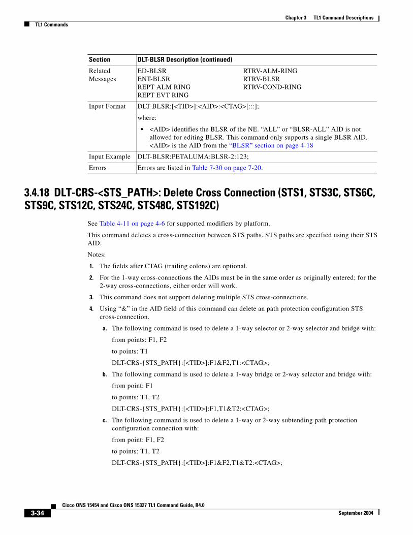
3.4.18 DLT-CRS-<STS_PATH>: Delete Cross Connection (STS1, STS3C, STS6C, STS9C, STS12C, STS24C, STS48C, STS192C)
See Table 4-11 on page 4-6 for supported modifiers by platform.
This command deletes a cross-connection between STS paths. STS paths are specified using their STS AID.
Notes:
1. The fields after CTAG (trailing colons) are optional.
2. For the 1-way cross-connections the AIDs must be in the same order as originally entered; for the 2-way cross-connections, either order will work.
3. This command does not support deleting multiple STS cross-connections.
4. Using “&” in the AID field of this command can delete an path protection configuration STS cross-connection.
a. The following command is used to delete a 1-way selector or 2-way selector and bridge with:
from points: F1, F2
to points: T1
DLT-CRS-{STS_PATH}:[<TID>]:F1&F2,T1:<CTAG>;
b. The following command is used to delete a 1-way bridge or 2-way selector and bridge with:
from point: F1
to points: T1, T2
DLT-CRS-{STS_PATH}:[<TID>]:F1,T1&T2:<CTAG>;
c. The following command is used to delete a 1-way or 2-way subtending path protection configuration connection with:
from point: F1, F2
to points: T1, T2
DLT-CRS-{STS_PATH}:[<TID>]:F1&F2,T1&T2:<CTAG>;
Related Messages
ED-BLSR RTRV-ALM-RINGENT-BLSR RTRV-BLSRREPT ALM RING RTRV-COND-RINGREPT EVT RING
Input Format DLT-BLSR:[<TID>]:<AID>:<CTAG>[:::];
where:
• <AID> identifies the BLSR of the NE. “ALL” or “BLSR-ALL” AID is not allowed for editing BLSR. This command only supports a single BLSR AID. <AID> is the AID from the “BLSR” section on page 4-18
Input Example DLT-BLSR:PETALUMA:BLSR-2:123;
Errors Errors are listed in Table 7-30 on page 7-20.
Section DLT-BLSR Description (continued)
3-34Cisco ONS 15454 and Cisco ONS 15327 TL1 Command Guide, R4.0
September 2004

Chapter 3 TL1 Command DescriptionsTL1 Commands
d. The AID format in the deletion command is the same as the AID format in the retrieved response message. For example, if the output of any retrieved AID is “F1&F2,T1:CCT,STS3C”, the deletion command with the AID format (F1&F2,T1) is required to delete this cross-connection.
3-35Cisco ONS 15454 and Cisco ONS 15327 TL1 Command Guide, R4.0
September 2004

Chapter 3 TL1 Command DescriptionsTL1 Commands
e. The following command is used to create a path protection configuration IDRI Cross-Connection:
ENT-CRS-{STS_PATH}:[<TID>]:A&B,C&D:<CTAG>::2WAYDC;
A–Path on ring X to which traffic from ring Y is bridged
B–Path on ring X to which traffic from the same ring is bridged
C–Path on ring Y to which traffic from ring X is bridged
D–Path on ring Y to which traffic from the same ring is bridged
A, B, C, and D have a positional meaning. Connection type 2WAYDC is used for path protection configuration IDRI cross-connections.
f. The following command is used to create a path protection configuration DRI Cross-Connection:
ENT-CRS-{STS_PATH}:[<TID>]:A&B,C:<CTAG>::2WAYDC;
A–Path on ring X to which traffic from ring Y is bridged
B–Path on ring X to which traffic from the same ring is bridged
C–Traffic to and from ring Y
A, B, C, and D have a positional meaning. Connection type 2WAYDC is used for path protection configuration DRI cross-connections.
5. All A&B AIDs in the TL1 cross-connection command are in the format of WorkingAID&ProtectAID.
6. You can experience some implementation behavior problems if additional drops have been added to the connection object.
7. The facility AID is only valid for slots holding the G1000-4 card.
8. The virtual facility AID (VFAC) is only valid on slots holding an ML-series card.
9. A TL1 cross-connect that has been upgraded to a CTC circuit can no longer be managed by TL1. For example, if you issue a DLT-CRS-<STS_PATH> command to delete a circuit, you will see that the circuit still appears in CTC as “incomplete”. The reason for this is because in addition to creating cross-connects (as TL1 does), CTC creates another object on the source node that stores network-level circuit attributes. CTC will continue to see that object after the cross-connect is deleted which is why it shows an incomplete circuit.
Section DLT-CRS-<STS_PATH> Description
Category Cross Connections
Security Provisioning
Related Messages
DLT-CRS-VT1ED-CRS-<STS_PATH>ED-CRS-VT1ENT-CRS-<STS_PATH>ENT-CRS-VT1RTRV-CRSRTRV-CRS-<STS_PATH>RTRV-CRS-VT1
3-36Cisco ONS 15454 and Cisco ONS 15327 TL1 Command Guide, R4.0
September 2004
Chapter 3 TL1 Command DescriptionsTL1 Commands
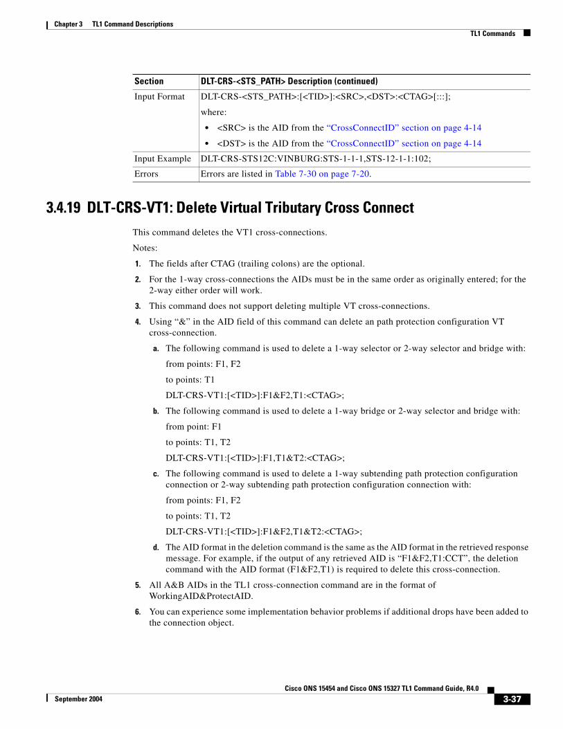
3.4.19 DLT-CRS-VT1: Delete Virtual Tributary Cross ConnectThis command deletes the VT1 cross-connections.
Notes:
1. The fields after CTAG (trailing colons) are the optional.
2. For the 1-way cross-connections the AIDs must be in the same order as originally entered; for the 2-way either order will work.
3. This command does not support deleting multiple VT cross-connections.
4. Using “&” in the AID field of this command can delete an path protection configuration VT cross-connection.
a. The following command is used to delete a 1-way selector or 2-way selector and bridge with:
from points: F1, F2
to points: T1
DLT-CRS-VT1:[<TID>]:F1&F2,T1:<CTAG>;
b. The following command is used to delete a 1-way bridge or 2-way selector and bridge with:
from point: F1
to points: T1, T2
DLT-CRS-VT1:[<TID>]:F1,T1&T2:<CTAG>;
c. The following command is used to delete a 1-way subtending path protection configuration connection or 2-way subtending path protection configuration connection with:
from points: F1, F2
to points: T1, T2
DLT-CRS-VT1:[<TID>]:F1&F2,T1&T2:<CTAG>;
d. The AID format in the deletion command is the same as the AID format in the retrieved response message. For example, if the output of any retrieved AID is “F1&F2,T1:CCT”, the deletion command with the AID format (F1&F2,T1) is required to delete this cross-connection.
5. All A&B AIDs in the TL1 cross-connection command are in the format of WorkingAID&ProtectAID.
6. You can experience some implementation behavior problems if additional drops have been added to the connection object.
Input Format DLT-CRS-<STS_PATH>:[<TID>]:<SRC>,<DST>:<CTAG>[:::];
where:
• <SRC> is the AID from the “CrossConnectID” section on page 4-14
• <DST> is the AID from the “CrossConnectID” section on page 4-14
Input Example DLT-CRS-STS12C:VINBURG:STS-1-1-1,STS-12-1-1:102;
Errors Errors are listed in Table 7-30 on page 7-20.
Section DLT-CRS-<STS_PATH> Description (continued)
3-37Cisco ONS 15454 and Cisco ONS 15327 TL1 Command Guide, R4.0
September 2004

Chapter 3 TL1 Command DescriptionsTL1 Commands
3.4.20 DLT-EQPT: Delete EquipmentThis command deletes a card from the NE.
This command removes the card type and attributes that were entered for a particular slot. If any facilities are assigned, they are deleted too. The command will be denied if the card is part of a protection group or has a cross-connect end-point.
To delete a card that is part of a protection group, it has to be removed from the protection group first using the ED-EQPT command.
Error conditions for deleting equipment may be:
1. If the equipment is in use which corresponds to some provisioning having been done on the equipment, the SPLD (Equipment in use) error message will be returned:
a. If it is belongs to a protection group that has a cross-connection.
b. If one of its ports has been provisioned as a DCC channel.
c. If one of its ports is being used for a synchronization source.
d. If the equipment has a Test Access Point (TAP).
e. If one of its ports is being used as a UCP Control Channel or Interface.
f. If one of its ports is provisioned for a BLSR.
g. If one of its ports is a part of a 1+1 protection group.
2. If a card is not provisioned, an error message will be returned.
Section DLT-CRS-VT1 Description
Category Cross Connections
Security Provisioning
Related Messages
DLT-CRS-<STS_PATH>ED-CRS-<STS_PATH>ED-CRS-VT1ENT-CRS-<STS_PATH>ENT-CRS-VT1RTRV-CRSRTRV-CRS-<STS_PATH>RTRV-CRS-VT1
Input Format DLT-CRS-VT1:[<TID>]:<FROM>,<TO>:<CTAG>[:::];
where:
• <FROM> indicates an identifier at one end of the VT cross-connection; <FROM> is the AID from the “VT1_5” section on page 4-30
• <TO> indicates an identifier at the other end of the VT cross-connection; <TO> is the AID from the “VT1_5” section on page 4-30
Input Example DLT-CRS-VT1:CISCO:VT1-2-3-7-2,VT1-4-4-5-2:1234;
Errors Errors are listed in Table 7-30 on page 7-20.
3-38Cisco ONS 15454 and Cisco ONS 15327 TL1 Command Guide, R4.0
September 2004

Chapter 3 TL1 Command DescriptionsTL1 Commands
3.4.21 DLT-FFP-<OCN_TYPE>: Delete Facility Protection Group (OC3, OC12, OC48, OC192)
See Table 4-11 on page 4-6 for supported modifiers by platform.
This command deletes an OCN facility protection group in a 1+1 architecture.
Note If the protection group does not exist, an error message will be returned.
Section DLT-EQPT Description
Category Equipment
Security Provisioning
Related Messages
ALW-SWDX-EQPT REPT ALM EQPTALW-SWTOPROTN-EQPT REPT EVT EQPTALW-SWTOWKG-EQPT RTRV-ALM-EQPTED-EQPT RTRV-COND-EQPTENT-EQPT RTRV-EQPTINH-SWDX-EQPT SW-DX-EQPTINH-SWTOPROTN-EQPT SW-TOPROTN-EQPTINH-SWTOWKG-EQPT SW-TOWKG-EQPT
Input Format DLT-EQPT:[<TID>]:<AID>:<CTAG>[:::];
where:
• <AID> is the equipment unit (slot) to act on and is the AID from the “EQPT” section on page 4-21
Input Example DLT-EQPT:SONOMA:SLOT-1:104;
Errors Errors are listed in Table 7-30 on page 7-20.
Section DLT-FFP-<OCN_TYPE> Description
Category SONET Line Protection
Security Provisioning
Related Messages
ED-FFP-<OCN_TYPE>ENT-FFP-<OCN_TYPE>EX-SW-<OCN_BLSR>OPR-PROTNSW-<OCN_TYPE>RLS-PROTNSW-<OCN_TYPE>RTRV-FFP-<OCN_TYPE>RTRV-PROTNSW-<OCN_TYPE>
Input Format DLT-FFP-<OCN_TYPE>:[<TID>]:<WORK>,<PROTECT>:<CTAG>[:::];
where:
• <WORK> identifies the working facility and is the AID from the “FACILITY” section on page 4-22
• <PROTECT> identifies the protect facility and is the AID “FACILITY” section on page 4-22
3-39Cisco ONS 15454 and Cisco ONS 15327 TL1 Command Guide, R4.0
September 2004

Chapter 3 TL1 Command DescriptionsTL1 Commands
3.4.22 DLT-FFP-CLNT: Delete Facility Protection Group ClientThis command deletes Y cable protection on client facilities.
Input Example DLT-FFP-OC3:PETALUMA:FAC-2-1,FAC-1-1:1;
Errors Errors are listed in Table 7-30 on page 7-20.
Section DLT-FFP-<OCN_TYPE> Description (continued)
Section DLT-FFP-CLNT Description
Category DWDM
Security Provisioning
Related Messages
DLT-FFP-<OCN_TYPE> RLS-PROTNSW-<OCN_TYPE>ED-CLNT RLS-PROTNSW-CLNTED-DWDM RTRV-CLNTED-FFP-<OCN_TYPE> RTRV-DWDMED-FFP-CLNT RTRV-FFP-<OCN_TYPE>ED-OCH RTRV-FFP-CLNTED-TRC-CLNT RTRV-OCHED-TRC-OCH RTRV-PROTNSW-<OCN_TYPE>ENT-FFP-<OCN_TYPE> RTRV-PROTNSW-CLNTENT-FFP-CLNT RTRV-TRC-CLNTOPR-PROTNSW-<OCN_TYPE> RTRV-TRC-OCHOPR-PROTNSW-CLNT
Input Format DLT-FFP-CLNT:[<TID>]:<WORKAID>,<PROTAID>:<CTAG>[:::];
where:
• <WORKAID> identifies the working facility and is the AID from the “FACILITY” section on page 4-22
• <PROTECTAID> identifies the protect facility and is the AID “FACILITY” section on page 4-22
Input Example DLT-FFP-CLNT:CISCO:FAC-1-1,FAC-2-1:100;
Errors Errors are listed in Table 7-30 on page 7-20.
3-40Cisco ONS 15454 and Cisco ONS 15327 TL1 Command Guide, R4.0
September 2004

Chapter 3 TL1 Command DescriptionsTL1 Commands
3.4.23 DLT-UCP-CC: Delete Unified Control Plane Control Channel(Cisco ONS 15454 only)
This command deletes a UCP IP control channel.
1. If you send this command to a control channel that is in use, a SRQN (Status, Invalid Request) error message is returned.
2. If sending this command to delete an SDCC IPCC with a complete result, the SDCC of the specified SONET line is deleted (or disabled) automatically with a DB change reporting (if the DB change report is enabled).
3. If sending this command to delete an IPCC which is in use by a UCP Interface, an SROF (Delete UCP IPCC Failed - Object Is In Use) error message is returned.
Section DLT-UCP-CC Description
Category UCP
Security Provisioning
Related Messages
DLT-UCP-IF ENT-UCP-NBRDLT-UCP-NBR REPT ALM UCPED-UCP-CC REPT EVT UCPED-UCP-IF RTRV-ALM-UCPED-UCP-NBR RTRV-COND-UCPED-UCP-NODE RTRV-UCP-CCENT-UCP-CC RTRV-UCP-IFENT-UCP-IF RTRV-UCP-NBR
Input Format DLT-UCP-CC:[<TID>]:<AID>:<CTAG>[::::];
where:
• <AID> indicates an individual IPCC ID; <AID> is the AID from the “IPCC” section on page 4-16
Input Example DLT-UCP-CC:CISCO:CC-9:CTAG;
Errors Errors are listed in Table 7-30 on page 7-20.
3-41Cisco ONS 15454 and Cisco ONS 15327 TL1 Command Guide, R4.0
September 2004

Chapter 3 TL1 Command DescriptionsTL1 Commands
3.4.24 DLT-UCP-IF: Delete Unified Control Plane InterfaceThis command deletes a UCP interface.
Note If the UCP interface is not found or in use, a SRQN (Status, Invalid Request) error message is returned.
3.4.25 DLT-UCP-NBR: Delete Unified Control Plane NeighborThis command deletes a UCP neighbor.
Notes:
1. If the neighbor is in use, an SRQN (Status, Invalid Request) error message is returned.
2. If sending this command to delete a neighbor which is in use by IPCC, an SROF (Delete UCP neighbor Failed - Object Is In Use) error message is returned.
Section DLT-UCP-IF Description
Category UCP
Security Provisioning
Related Messages
DLT-UCP-CC ENT-UCP-NBRDLT-UCP-NBR REPT ALM UCPED-UCP-CC REPT EVT UCPED-UCP-IF RTRV-ALM-UCPED-UCP-NBR RTRV-COND-UCPED-UCP-NODE RTRV-UCP-CCENT-UCP-CC RTRV-UCP-IFENT-UCP-IF RTRV-UCP-NBR
Input Format DLT-UCP-IF:[<TID>]:<AID>:<CTAG>[::::];
where:
• <AID> indicates the interface port index of the data link; <AID> is the AID from the “FACILITY” section on page 4-22
Input Example DLT-UCP-IF:CISCO:FAC-2-1:CTAG;
Errors Errors are listed in Table 7-30 on page 7-20.
Section DLT-UCP-NBR Description
Category UCP
Security Provisioning
Related Messages
DLT-UCP-CC ENT-UCP-NBRDLT-UCP-IF REPT ALM UCPED-UCP-CC REPT EVT UCPED-UCP-IF RTRV-ALM-UCPED-UCP-NBR RTRV-COND-UCPED-UCP-NODE RTRV-UCP-CCENT-UCP-CC RTRV-UCP-IFENT-UCP-IF RTRV-UCP-NBR
3-42Cisco ONS 15454 and Cisco ONS 15327 TL1 Command Guide, R4.0
September 2004

Chapter 3 TL1 Command DescriptionsTL1 Commands
3.4.26 DLT-USER-SECU: Delete User SecurityThis command deletes a user and can only be performed by a Superuser. Privilege levels are described in the ENT-USER-SECU command.
This command cannot be used to delete a user that is currently logged on.
For the DLT-USER-SECU command:
DLT-USER-SECU:[TID]:<UID>:[CTAG];
the syntax of <UID> is not checked. The user is deleted if the <UID> exists in the database.
Notes:
1. A userid cannot be deleted when that user is logged in. If you try to delete a userid and the user is logged in, an error message indicating that the user is logged in will be received.
Input Format DLT-UCP-NBR:[<TID>]:<AID>:<CTAG>[::::];
where:
• <AID> indicates an individual neighbor AID of the UCP; <AID> is the AID from the “NBR” section on page 4-16
Input Example DLT-UCP-NBR:CISCO:NBR-8:CTAG;
Errors Errors are listed in Table 7-30 on page 7-20.
Section DLT-UCP-NBR Description (continued)
Section DLT-USER-SECU Description
Category Security
Security Superuser
Related Messages
ACT-USERCANCCANC-USERED-PIDED-USER-SECUENT-USER-SECUREPT EVT SECURTRV-USER-SECU
Input Format DLT-USER-SECU:[<TID>]:<UID>:<CTAG>;
where:
• <UID> is the user identifier and is a string; <UID> is any combination of up to 10 alphanumeric characters
Note CTC allows <UID> and <PID> of up to 20 characters. The 20 character CTC-entered <UID> and <PID> are not valid TL1 <UID> and <PID>.
Input Example DLT-USER-SECU:PETALUMA:CISCO15:123;
Errors Errors are listed in Table 7-30 on page 7-20.
3-43Cisco ONS 15454 and Cisco ONS 15327 TL1 Command Guide, R4.0
September 2004

Chapter 3 TL1 Command DescriptionsTL1 Commands
3.4.27 ED-<OCN_TYPE>: Edit (OC3, OC12, OC48, OC192)See Table 4-11 on page 4-6 for supported modifiers by platform.
This command edits the attributes (i.e., service parameters) and state of an OC-N facility. Allowable states for a facility are Out Of Service (OOS), Out Of Service with Automatic In Service transitioning (OOS-AINS), Out Of Service for Maintenance (OOS-MT), and In Service (IS).
The DCC transmit is bridged to both working and protect in a 1+1 configuration. On the receive side, the active one is selected for DCC. The DCC is provisioned on the working port only in a 1+1 configuration.
All lines in a 1+1 BLSR must have the same mode. If you change the mode of a line that is in a 1+1 BLSR, an error message will be returned.
UNI-C DCC provisioning notes:
1. The attributes DCC(Y/N) and mode (SONET/SDH) remain the same in the ED/RTRV-OCN commands when the DCC is used for UNI-C, in which case the port attribute UNIC is enables (UNIC=Y).
2. If the DCC is created under regular SONET provisioning, and this port is used by UNI-C, the port is converted as a UNI-C DCC automatically.
3. De-provisioning UNI-C IF/IB IPCC will free up DCC termination automatically.
4. The state of the T1 port cannot be changed to IS or OOS if a loopback has been operated upon the line.
Section ED-<OCN_TYPE> Description
Category Ports
Security Provisioning
Related Messages
ED-DS1ED-EC1ED-G1000ED-T1ED-T3RMV-<MOD2_IO>RST-<MOD2_IO>RTRV-<OCN_TYPE>RTRV-DS1RTRV-EC1RTRV-G1000RTRV-T1RTRV-T3
3-44Cisco ONS 15454 and Cisco ONS 15327 TL1 Command Guide, R4.0
September 2004

Chapter 3 TL1 Command DescriptionsTL1 Commands
3.4.28 ED-<STS_PATH>: Edit (STS1, STS3C, STS6C, STS9C, STS12C, STS24C, STS48C, STS192C)
See Table 4-11 on page 4-6 for supported modifiers by platform.
This command edits the attributes associated with an STS path.
The SFBER, SDBER, RVRTV, and RVTM parameters only apply to path protection configuration.
Input Format ED-<OCN_TYPE>:[<TID>]:<AID>:<CTAG>:::[DCC=<DCC>,][SYNCMSG=<SYNCMSG>,][SENDDUS=<SENDDUS>,][PJMON=<PJMON>,][SFBER=<SFBER>,][SDBER=<SDBER>,][MODE=<MODE>,][MUX=<MUX>,][SOAK=<SOAK>]:[<PST>],[<SST>];
where:
• <AID> is the access identifier from the “FACILITY” section on page 4-22
• <DCC> identifies an OCN port DCC connection; valid values for <DCC> are shown in the “SDCC_MODE” section on page 4-86
• <SYNCMSG> indicates if sync status messaging is enabled or disabled on the facility; valid values for <SYNCMSG> are shown in the “ON_OFF” section on page 4-79
• <SENDDUS> indicates that the facility will send out the DUS (do not use for synchronization) value as the sync status message for that facility; valid values are shown in the “ON_OFF” section on page 4-79
• <PJMON> identifies an OC-N port PJMON with a value range of [0, highest STS number for the sonet card]; <PJMON> is an integer
• <SFBER> identifies an OC-N port SFBER; valid values for <SFBER> are shown in the “SF_BER” section on page 4-86
• <SDBER> identifies an OC-N port SDBER; valid values for <SDBER> are shown in the “SD_BER” section on page 4-85
• Valid values for <MODE> are shown in the “OPTICAL_MODE” section on page 4-80
• <MUX> BLSR Extension Byte (supported only on OC48AS cards); valid values for <MUX> are shown in the “MUX_TYPE” section on page 4-78
• <SOAK> OOS-AINS to IS transition soak time as measured in 15 minute intervals, so a value of 4 translates to a soak time of 1 hour. The allowable range is 0–192 intervals (maximum of 48 hours). <SOAK> is an integer.
• <PST> is the primary state; valid values for <PST> are shown in the “PST” section on page 4-85
• <SST> is the secondary state; valid values for <SST> are shown in the “SST” section on page 4-87
Input Example ED-OC48:PENNGROVE:FAC-6-1:114:::DCC=Y,SYNCMSG=Y,SENDDUS=N,PJMON=48,SFBER=1E-4,SDBER=1E-6,MODE=SONET,MUX=E2,SOAK=10:OOS,AINS;
Errors Errors are listed in Table 7-30 on page 7-20.
Section ED-<OCN_TYPE> Description (continued)
3-45Cisco ONS 15454 and Cisco ONS 15327 TL1 Command Guide, R4.0
September 2004

Chapter 3 TL1 Command DescriptionsTL1 Commands
The path trace message is a 64 character string including the terminating CR (carriage return) and LF (line feed) that is transported in the J1 byte of the SONET STS Path overhead. Both the EXPTRC and TRC string can be provisioned by user with up to 62 character string.
The EXPTRC indicates the contents of the expected incoming path trace are provisioned by the user. The TRC indicates the contents of the outgoing path trace message. The INCTRC indicates the contents of the incoming path trace message.
The path trace mode has three modes: OFF, MANUAL, and AUTO. The path trace mode defaults to OFF. The MANUAL mode performs the comparison of the received string with the user-entered expected string. The AUTO mode performs the comparison of the present received string with an expected string set to a previously received string. If there is a mismatch, TIM-P alarm is raised. When the path trace mode is in OFF mode, there is no path trace processing, and all the alarm and state conditions are reset.
The TACC parameter edits an existing single STS or VT and changes it to a test access point. When an editing command on TACC is executed, it assigns the STS for the first 2-way connection and STS=1 as the second 2-way connection. For STS3C and STS12C, the next available STS of the same width is chosen. For more information on TACC, refer to the “Test Access” section on page 1-17.
J1 is implemented on the DS1/DS1N, DS3E/DS3NE, DS3XM, EC1, OC3, OC48AS and OC192 cards.
DS3/DS3N, OC12, OC48, E100, and E1000 cards do not support path trace.
DS1/DS1N, DS3E/DS3NE, and DS3XM support both TRC and EXPTRC in the ED-STS-PATH command.
EC1, OC3, OC48AS, and OC192 only support EXPTRC in the ED-STS-PATH command.
Note Each TL1 command must be less than or equal to 255 characters. Any command larger than 255 characters must be split into multiple commands. For example, if you use the ED-<STS_PATH> command to edit the J1 EXPTRC/TRC message, path protection configuration attributes, and TACC attributes and the command exceeds 255 characters the command will not be processed. You must use multiple ED-<STS_PATH> commands instead.
Note An STS TAP created in a DS3XM card cannot be used to connect to an STS with a non-VT structured payload, for example, DS3. If created, traffic cannot be monitored.
Note An STS TAP created in a DS3 card cannot be used to connect to an STS with a non-DS3 payload, for example, VT structured. If created, traffic cannot be monitored.
Error conditions:
1. If sending this command to edit SFBER or SDBER or RVRTV or RVTM for the non path protection configuration STS path, an error message will be returned.
2. If sending this command to edit the EXPTRC string with the AUTO path trace mode (TRCMODE=AUTO), an error message will be returned.
3. If sending this command to edit TRC on any card other than DS3(N)E, DS1(N), and DS3XM cards, an error message (TRC-not allowed for monitor paths. Incorrect card type.) will be returned.
4. This command is allowed to edit EXPTRC on DS1(N), DS3(N)E, DS3XM, EC1, OC3, OC48AS, and OC192 cards.
5. If sending this command to edit both TACC and any other attribute(s), the (Parameters Not compatible) error message will be returned.
3-46Cisco ONS 15454 and Cisco ONS 15327 TL1 Command Guide, R4.0
September 2004
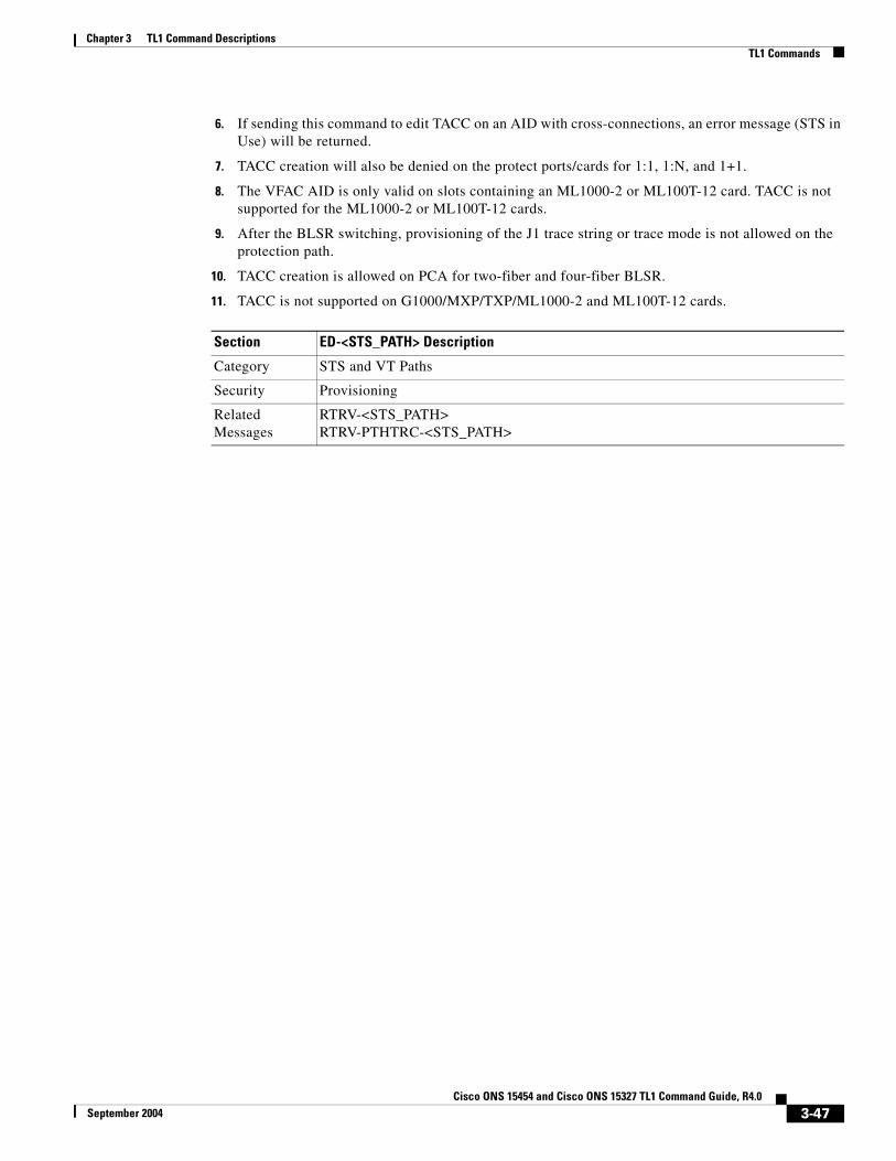
Chapter 3 TL1 Command DescriptionsTL1 Commands
6. If sending this command to edit TACC on an AID with cross-connections, an error message (STS in Use) will be returned.
7. TACC creation will also be denied on the protect ports/cards for 1:1, 1:N, and 1+1.
8. The VFAC AID is only valid on slots containing an ML1000-2 or ML100T-12 card. TACC is not supported for the ML1000-2 or ML100T-12 cards.
9. After the BLSR switching, provisioning of the J1 trace string or trace mode is not allowed on the protection path.
10. TACC creation is allowed on PCA for two-fiber and four-fiber BLSR.
11. TACC is not supported on G1000/MXP/TXP/ML1000-2 and ML100T-12 cards.
Section ED-<STS_PATH> Description
Category STS and VT Paths
Security Provisioning
Related Messages
RTRV-<STS_PATH>RTRV-PTHTRC-<STS_PATH>
3-47Cisco ONS 15454 and Cisco ONS 15327 TL1 Command Guide, R4.0
September 2004

Chapter 3 TL1 Command DescriptionsTL1 Commands
Input Format ED-<STS_PATH>:[<TID>]:<SRC>:<CTAG>:::[SFBER=<SFBER>,][SDBER=<SDBER>,][RVRTV=<RVRTV>,][RVTM=<RVTM>,][SWPDIP=<SWPDIP>,][HOLDOFFTIMER=<HOLDOFFTIMER>,][EXPTRC=<EXPTRC>,][TRC=<TRC>,][TRCMODE=<TRCMODE>,][TACC=<TACC>]:[<PST>],[<SST>];
where:
• <SRC> is the access identifier from the “CrossConnectID” section on page 4-14
• <SFBER> identifies an STS path SFBER which only applies to path protection configuration; valid values for <SFBER> are shown in the “SF_BER” section on page 4-86
• <SDBER> identifies an STS path SDBER which only applies to path protection configuration; valid values for <SDBER> are shown in the “SD_BER” section on page 4-85
• <RVRTV> identifies a revertive mode which only applies to path protection configuration; valid values for <RVRTV> are shown in the “ON_OFF” section on page 4-79
• <RVTM> identifies a revertive time which only applies to path protection configuration; valid values for <RVTM> are shown in the “REVERTIVE_TIME” section on page 4-85. <RVTM> is not allowed to be set while <RVRTV> is N.
• <SWPDIP> On-Off switch for path protection configuration Payload Defect Level switching. Valid values for <SWPDIP> are shown in the “ON_OFF” section on page 4-79
• <HOLDOFFTIMER> Hold-off timer for path protection configuration DRI; <HOLDOFFTIMER> is an integer
• <EXPTRC> indicates the expected path trace message (J1) contents. The EXPTRC is any 64 character string, including the terminating CR (carriage return) and LF (line feed); <EXPTRC> is a string
• <TRC> identifies the path trace message to be transmitted. The TRC is any combination of 64 characters, including the terminating CR and LF. The trace byte (J1) continuously transmits a 64 byte string, one byte at a time. A null value defaults to the NE transmitting null characters (Hex 00); <TRC> is a string
• <TRCMODE> indicates the path trace mode, and defaults to the OFF mode; valid values for <TRCMODE> are shown in the “TRCMODE” section on page 4-94
• <TACC> is the AID “TACC” section on page 4-29
• <PST> is the primary state; valid values for <PST> are shown in the “PST” section on page 4-85
• <SST> is the secondary state; valid values for <SST> are shown in the “SST” section on page 4-87
Input Example ED-STS1:FERNDALE:STS-2-1-4:115:::SFBER=1E-3,SDBER=1E-5,RVRTV=Y,RVTM=1.0,SWPDIP=Y,HOLDOFFTIMER=2000,EXPTRC=“EXPTRCSTRING”,TRC=“TRCSTRING”,TRCMODE=OFF,TACC=8:OOS,AINS;
Errors Errors are listed in Table 7-30 on page 7-20.
Section ED-<STS_PATH> Description (continued)
3-48Cisco ONS 15454 and Cisco ONS 15327 TL1 Command Guide, R4.0
September 2004

Chapter 3 TL1 Command DescriptionsTL1 Commands
3.4.29 ED-BITS: Edit Building Integrated Timing SupplyThis command edits the BITS reference attributes.
Section ED-BITS Description
Category Synchronization
Security Provisioning
Related Messages
ED-NE-SYNCN RTRV-ALM-BITSED-SYNCN RTRV-ALM-SYNCNOPR-SYNCNSW RTRV-BITSREPT ALM BITS RTRV-COND-BITSREPT ALM SYNCN RTRV-COND-SYNCNREPT EVT BITS RTRV-NE-SYNCNREPT EVT SYNCN RTRV-SYNCNRLS-SYNCNSW
Input Format ED-BITS:[<TID>]:<AID>:<CTAG>:::[LINECDE=<LINECDE>,][FMT=<FMT>,][LBO=<LBO>,][SYNCMSG=<SYNCMSG>,][AISTHRSHLD=<AISTHRSHLD>][:<PST>];
where:
• <AID> is an access identifier from the “BITS” section on page 4-18
• <LINECDE> is a line code; valid values for <LINECDE> are shown in the “LINE_CODE” section on page 4-70
• <FMT> is the frame format; valid values for <FMT> are shown in the “FRAME_FORMAT” section on page 4-69
• <LBO> indicates BITS line build out. The default value is 0-133. Valid values for <LBO> are shown in the “BITS_LineBuildOut” section on page 4-42
• <SYNCMSG> indicates if this BITS facility supports synchronization status message; <SYNCMSG> defaults to (Y) and valid values are shown in the “ON_OFF” section on page 4-79
• <AISTHRSHLD> is the AIS Threshold. Valid values for <AISTHRSHLD> shown in the “SYNC_CLOCK_REF_QUALITY_LEVEL” section on page 4-89
• <PST> is a state; valid values for <PST> are shown in the “PST” section on page 4-85
Input Example ED-BITS:SONOMA:BITS-2:779:::LINECDE=AMI,FMT=ESF,LBO=0-133,SYNCMSG=Y,AISTHRSHLD=PRS:IS;
Errors Errors are listed in Table 7-30 on page 7-20.
3-49Cisco ONS 15454 and Cisco ONS 15327 TL1 Command Guide, R4.0
September 2004

Chapter 3 TL1 Command DescriptionsTL1 Commands
3.4.30 ED-BLSR: Edit Bidirectional Line Switched RingThis command edits the BLSR attributes.
Notes:
1. Only the RVRTV, RVTM, SRVRTV, SRVTM attributes can be edited for the 4-Fiber BLSR.
2. Only the RVRTV and RVTM attributes can be edited for the 2-Fiber BLSR.
Error conditions:
1. If the system fails on getting IOR, a SDBE (Status, Internal Data Base Error) error message will be returned.
2. If the NE returns nothing for the required BLSR (BLSR-#, AID), a SRQN (Status, Invalid Request) error message will be returned.
3. If sending this command to modify any attribute other than RVRTV, RVTM, SRVRTV, and SRVTM on the 4-Fiber BLSR, an IDNV (Input, Data Not Valid) error message will be returned.
4. If sending this command to modify any attribute other than RVRTV or RVTM on the 2-fiber BLSR, an IDNV (Input, Data Not Valid) error message will be returned.
5. Both RINGID and NODEID can be edited using the ED-BLSR command starting with Release 3.2.
Section ED-BLSR Description
Category BLSR
Security Provisioning
Related Messages
DLT-BLSRENT-BLSRREPT ALM RINGREPT EVT RINGRTRV-ALM-RINGRTRV-BLSRRTRV-COND-RING
3-50Cisco ONS 15454 and Cisco ONS 15327 TL1 Command Guide, R4.0
September 2004
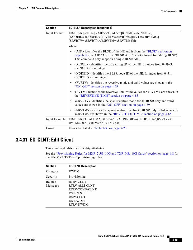
Chapter 3 TL1 Command DescriptionsTL1 Commands
3.4.31 ED-CLNT: Edit ClientThis command edits client facility attributes.
See the “Provisioning Rules for MXP_2.5G_10G and TXP_MR_10G Cards” section on page 1-8 for specific MXP/TXP card provisioning rules.
Input Format ED-BLSR:[<TID>]:<AID>:<CTAG>:::[RINGID=<RINGID>,][NODEID=<NODEID>,][RVRTV=<RVRTV>,][RVTM=<RVTM>,][SRVRTV=<SRVRTV>,][SRVTM=<SRVTM>][:];
where:
• <AID> identifies the BLSR of the NE and is from the “BLSR” section on page 4-18 (the AID “ALL” or “BLSR ALL” is not allowed for editing BLSR). This command only supports a single BLSR AID
• <RINGID> identifies the BLSR ring ID of the NE. It ranges from 0–9999. <RINGID> is an integer
• <NODEID> identifies the BLSR node ID of the NE. It ranges from 0–31. <NODEID> is an integer
• <RVRTV> identifies the revertive mode and valid values are shown in the “ON_OFF” section on page 4-79
• <RVTM> identifies the revertive time; valid values for <RVTM> are shown in the “REVERTIVE_TIME” section on page 4-85
• <SRVRTV> identifies the span revertive mode for 4F BLSR only and valid values are shown in the “ON_OFF” section on page 4-79
• <SRVTM> identifies the span revertive time for 4F BLSR only; valid values for <SRVTM> are shown in the “REVERTIVE_TIME” section on page 4-85
Input Example ED-BLSR:PETALUMA:BLSR-43:123:::RINGID=43,NODEID=3,RVRTV=Y,RVTM=2.0,SRVRTV=Y,SRVTM=5.0;
Errors Errors are listed in Table 7-30 on page 7-20.
Section ED-BLSR Description (continued)
Section ED-CLNT Description
Category DWDM
Security Provisioning
Related Messages
RTRV-CLNTRTRV-ALM-CLNTRTRV-COND-CLNTRST-CLNTRMV-CLNTED-DWDMRTRV-DWDM
3-51Cisco ONS 15454 and Cisco ONS 15327 TL1 Command Guide, R4.0
September 2004

Chapter 3 TL1 Command DescriptionsTL1 Commands
Input Format ED-CLNT:[<TID>]:<AID>:<CTAG>:::[SFBER=<SFBER>,][SDBER=<SDBER>,][ALSMODE=<ALSMODE>,][ALSRCINT=<ALSRCINT>,][ALSRCPW=<ALSRCPW>,][COMM=<COMM>,][MACADDR=<MACADDR>,][SYNCMSG=<SYNCMSG>,][SENDDUS=<SENDDUS>,][RLASER=<RLASER>][SOAK=<SOAK>]:[<PST>],[<SST>];
where:
• <AID> is from the “FACILITY” section on page 4-22
• <SFBER> identifies the SFBER for the SONET payload; valid values are shown in the “SF_BER” section on page 4-86
• <SDBER> identifies the SDBER for the SONET payload; valid values are shown in the “SD_BER” section on page 4-85
• <ALSMODE> indicates if the Automatic Laser Shutdown is enabled or disabled; valid values are shown in the “ALS_MODE” section on page 4-41
• <ALSRCINT> indicates the ALS recovery interval. Range is 100–300 seconds; <ALSRCINT> is an integer
• <ALSRCPW> indicates the ALS recovery pulse width. The range is 2–100 seconds, in increments of 100ms, e.g. 30.1; <ALSRCPW> is a float
• <COMM> indicates if the GCC or DCC is enabled or disabled. The GCC can be enabled only if the digital wrapper has been enabled for the card. The default is NONE. Valid values are shown in the “COMM_TYPE” section on page 4-46. Rules for a MXP/TXP Client port are; only the DCC can be provisioned, if the termination mode is not transparent and the payload is SONET. On a MXP/TXP DWDM port, the DCC can be enabled only if the G.709 is not enabled and if the payload is SONET and the termination mode is not transparent. On a MXP/TXP DWDM port, the GCC can be enabled if there is no DCC and the G.709 flag is enabled.
• <MACADDR> identifies the MAC address for the 10GEthernet payload; <MACADDR> is a string
• <SYNCMSG> indicates that the facility be enabled to provide the synchronization clock. This does not apply to a TXP card. This applies to an MXP card, only if the payload is SONET and the card termination mode is as follows: TRANSPARENT - All Client ports are available for all timing selections. All Trunk ports are not available. Valid values are shown in the “ON_OFF” section on page 4-79LINE - All ports are available for all-timing selections.
• <SENDDUS> indicates that the facility send out a Do not Use for Sync message. This does not apply to a TXP card. This applies to an MXP card, only if the payload is SONET and the card termination mode is as follows: TRANSPARENT - All Client ports are available for all timing selections. All Trunk ports are not available.LINE - All ports are available for all-timing selections. Valid values are shown in the “ON_OFF” section on page 4-79
Section ED-CLNT Description (continued)
3-52Cisco ONS 15454 and Cisco ONS 15327 TL1 Command Guide, R4.0
September 2004

Chapter 3 TL1 Command DescriptionsTL1 Commands
3.4.32 ED-CRS-<STS_PATH>:ED CRS (STS1, STS3C, STS6C, STS9C, STS12C, STS24C, STS 48C, STS192C)
This command edits the state of an STS cross-connection.
Input Format (continued)
• <RLASER> indicates if the laser should be restarted. This is applicable only if the ALSMODE is not automatic; valid values are shown in the “ON_OFF” section on page 4-79
• <SOAK> OOS-AINS to IS transition soak time as measured in 15–minute intervals. A value of 4 translates to a soak time of one hour. The allowable range is 0–192 intervals (maximum of 48–hours). <SOAK> is an integer
• <PST> primary state; valid values are shown in the “PST” section on page 4-85
• <SST> secondary state; valid values are shown in the “SST” section on page 4-87
Input Example ED-CLNT:CISCO:FAC-1-1:100:::SFBER=1E-4,SDBER=1E-5,ALSMODE=Y,ALSRCINT=30,ALSRCPW=35.1,COMM=DCC,MACADDR=00-0E-AA-BB-CC-FF,SYNCMSG=Y,SENDDUS=Y,RLASER=Y,SOAK=10:OOS,AINS;
Errors Errors are listed in Table 7-30 on page 7-20.
Section ED-CLNT Description (continued)
Section ED-CRS-<STS_PATH> Description
Category Cross Connections
Security Provisioning
Related Messages
DLT-CRS-<STS_PATH> ENT-CRS-VT1DLT-CRS-VT1 RTRV-CRSED-CRS-VT1 RTRV-CRS-<STS_PATH>ENT-CRS-<STS_PATH> RTRV-CRS-VT1
Input Format ED-CRS-<STS_PATH>:[<TID>]:<SRC>,<DST>:<CTAG>:::[ADD=<ADD>,][REMOVE=<REMOVE>]:[<PST>],[<SST>];
where:
• <SRC> is the AID from the “CrossConnectID” section on page 4-14
• <DST> is the AID from the “CrossConnectID” section on page 4-14
• <ADD> is the AID from the “CrossConnectID” section on page 4-14
• <REMOVE> is the AID from the “CrossConnectID” section on page 4-14
• <PST> primary state; valid values for <PST> are shown in the “PST” section on page 4-85
• <SST> secondary state; valid values for <SST> are shown in the “SST” section on page 4-87
Input Example ED-CRS-STS1::STS-1-1-1,STS-2-1-1:1:::ADD=STS-13-1-1,REMOVE=STS-2-1-1:OOS,AINS;
Errors Errors are listed in Table 7-30 on page 7-20.
3-53Cisco ONS 15454 and Cisco ONS 15327 TL1 Command Guide, R4.0
September 2004

Chapter 3 TL1 Command DescriptionsTL1 Commands
3.4.33 ED-CRS-VT1: Edit Cross Connection VT1This command edits a VT cross-connection.
Note It is not possible to use both ADD and REMOVE at the same time.
Section ED-CRS-VT1 Description
Category Cross Connections
Security Provisioning
Related Messages
DLT-CRS-<STS_PATH> ENT-CRS-VT1DLT-CRS-VT1 RTRV-CRSED-CRS-<STS_PATH> RTRV-CRS-<STS_PATH>ENT-CRS-<STS_PATH> RTRV-CRS-VT1
Input Format ED-CRS-VT1:[<TID>]:<SRC>,<DST>:<CTAG>::::[ADD=<ADD>,][REMOVE=<REMOVE>]:[<PST>],[<SST>];
where:
• <SRC> is the AID from the “VT1_5” section on page 4-30
• <DST> is the AID from the “VT1_5” section on page 4-30
• <ADD> is the AID from the “VT1_5” section on page 4-30
• <REMOVE> is the AID from the “VT1_5” section on page 4-30
• <PST> primary state; valid values for <PST> are shown in the “PST” section on page 4-85
• <SST> secondary state; valid values for <SST> are shown in the “SST” section on page 4-87
Input Example ED-CRS-VT1::VT1-1-1-1-1-1,VT1-2-1-1-1-1:1:::ADD=VT1-3-1-1-1-1,REMOVE=VT1-2-1-1-1-1:OOS,AINS;
Errors Errors are listed in Table 7-30 on page 7-20.
3-54Cisco ONS 15454 and Cisco ONS 15327 TL1 Command Guide, R4.0
September 2004

Chapter 3 TL1 Command DescriptionsTL1 Commands
3.4.34 ED-DAT: Edit Date and TimeThis command edits the date and the time
3.4.35 ED-DS1: Edit DS1(Cisco ONS 15454 only)
This command edits the test access attribute for DS1 access on a DS3XM card.
Note This command is not allowed if the card is a protecting card.
Section ED-DAT Description
Category System
Security Provisioning
Related Messages
ALM-MSG-ALL RTRV-HDRAPPLY RTRV-INVCOPY-RFILE RTRV-MAP-NETWORKED-NE-GEN RTRV-NE-GENED-NE-SYNCN RTRV-NE-IPMAPINH-MSG-ALL RTRV-NE-SYNCNINIT-SYS RTRV-TODREPT EVT FXFR SET-TOD
Input Format ED-DAT:[<TID>]::<CTAG>::[<DATE>],[<TIME>];
where:
• <DATE> identifies the date and is a string
• <TIME> identifies the time and is a string
Input Example ED-DAT:CISCO::1234::99-12-21,14-35-15;
Errors Errors are listed in Table 7-30 on page 7-20.
Section ED-DS1 Description
Category Ports
Security Provisioning
Related Messages
ED-<OCN_TYPE> RTRV-<OCN_TYPE>ED-EC1 RTRV-DS1ED-G1000 RTRV-EC1ED-T1 RTRV-G1000ED-T3 RTRV-T1RMV-<MOD2_IO> RTRV-T3RST-<MOD2_IO>
3-55Cisco ONS 15454 and Cisco ONS 15327 TL1 Command Guide, R4.0
September 2004
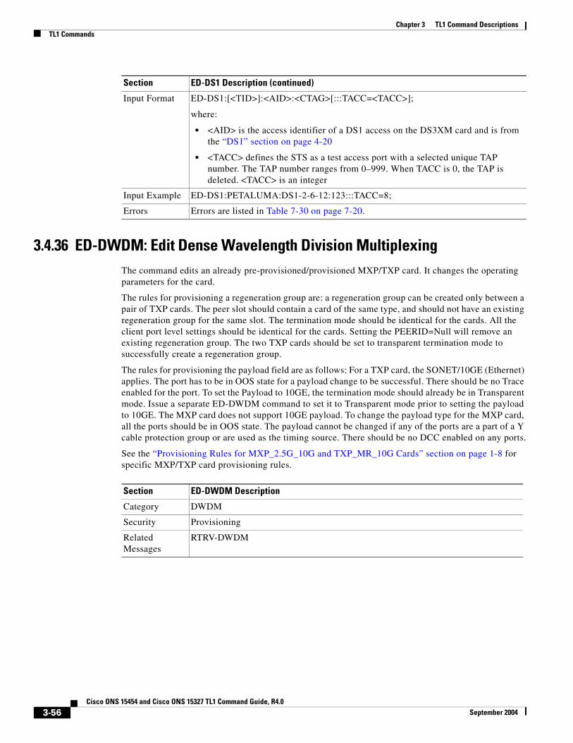
Chapter 3 TL1 Command DescriptionsTL1 Commands
3.4.36 ED-DWDM: Edit Dense Wavelength Division MultiplexingThe command edits an already pre-provisioned/provisioned MXP/TXP card. It changes the operating parameters for the card.
The rules for provisioning a regeneration group are: a regeneration group can be created only between a pair of TXP cards. The peer slot should contain a card of the same type, and should not have an existing regeneration group for the same slot. The termination mode should be identical for the cards. All the client port level settings should be identical for the cards. Setting the PEERID=Null will remove an existing regeneration group. The two TXP cards should be set to transparent termination mode to successfully create a regeneration group.
The rules for provisioning the payload field are as follows: For a TXP card, the SONET/10GE (Ethernet) applies. The port has to be in OOS state for a payload change to be successful. There should be no Trace enabled for the port. To set the Payload to 10GE, the termination mode should already be in Transparent mode. Issue a separate ED-DWDM command to set it to Transparent mode prior to setting the payload to 10GE. The MXP card does not support 10GE payload. To change the payload type for the MXP card, all the ports should be in OOS state. The payload cannot be changed if any of the ports are a part of a Y cable protection group or are used as the timing source. There should be no DCC enabled on any ports.
See the “Provisioning Rules for MXP_2.5G_10G and TXP_MR_10G Cards” section on page 1-8 for specific MXP/TXP card provisioning rules.
Input Format ED-DS1:[<TID>]:<AID>:<CTAG>[:::TACC=<TACC>];
where:
• <AID> is the access identifier of a DS1 access on the DS3XM card and is from the “DS1” section on page 4-20
• <TACC> defines the STS as a test access port with a selected unique TAP number. The TAP number ranges from 0–999. When TACC is 0, the TAP is deleted. <TACC> is an integer
Input Example ED-DS1:PETALUMA:DS1-2-6-12:123:::TACC=8;
Errors Errors are listed in Table 7-30 on page 7-20.
Section ED-DS1 Description (continued)
Section ED-DWDM Description
Category DWDM
Security Provisioning
Related Messages
RTRV-DWDM
3-56Cisco ONS 15454 and Cisco ONS 15327 TL1 Command Guide, R4.0
September 2004

Chapter 3 TL1 Command DescriptionsTL1 Commands
3.4.37 ED-EC1: Edit Electrical Carrier(Cisco ONS 15454 only)
This command edits the attributes of an EC1.
Notes:
1. This command is not allowed if the card is a protecting card.
2. The state of the T1 port cannot be changed to IS or OOS if a loopback has been operated upon the line.
Input Format ED-DWDM:[<TID>]:<AID>:<CTAG>:::[PEERID=<PEERID>,][TERMMODE=<TERMMODE>,][PAYLOAD=<PAYLOAD>,][PWL=<PWL>];
where:
• <AID> is from the “EQPT” section on page 4-21
• <PEERID> is from the “EQPT” section on page 4-21
• <TERMMODE> indicates the termination mode of the card; valid values are shown in the “TERM_MODE” section on page 4-93
• <PAYLOAD> is the type of payload carried; valid values are shown in the “PAYLOAD” section on page 4-83
• <PWL> is the provisioned wavelength; valid values are shown in the “OPTICAL_WLEN” section on page 4-81
Input Example ED-DWDM:VA454-22:SLOT-1:100:::PEERID=SLOT-2,TERMMODE=TRANS,PAYLOAD=SONET,PWL=1546.52;
Errors Errors are listed in Table 7-30 on page 7-20.
Section ED-DWDM Description (continued)
Section ED-EC1 Description
Category Ports
Security Provisioning
Related Messages
ED-<OCN_TYPE> RTRV-<OCN_TYPE>ED-DS1 RTRV-DS1ED-G1000 RTRV-EC1ED-T1 RTRV-G1000ED-T3 RTRV-T1RMV-<MOD2_IO> RTRV-T3RST-<MOD2_IO>
3-57Cisco ONS 15454 and Cisco ONS 15327 TL1 Command Guide, R4.0
September 2004

Chapter 3 TL1 Command DescriptionsTL1 Commands
3.4.38 ED-EQPT: Edit EquipmentThis command edits the attributes for a given equipment slot in the NE. If the card is in an equipment slot, this command is allowed only on the working AID.
The PROTID parameter indicates the unique identifier of the protection group (the protect card). “NULL” is a special value of the PROTID parameter and indicates absence of a protection group. For 1:1 protection type, RVRTV and RVTM parameters can be changed. For 1:1 protection type, if the PROTID parameter is entered as “NULL”, the protection group is deleted.
ED-EQPT:[<TID>]:SLOT-2:<CTAG>:::PROTID=NULL;
For 1:N protection type, if the PROTID is “NULL”, the AIDs in the list are removed from the protection group. If all the working cards are in the AID list, the protection group is deleted.
Example: if Slot-1, Slot-2 and Slot-4 were the only working cards in the protection group. The following command will remove Slot-4 from the protection group:
ED-EQPT:[<TID>]:SLOT-4:<CTAG>:::PROTID=NULL;
The protection group still has Slot-1 and Slot-2 as working cards.
The following command will remove all the other working cards in the above example and consequently, delete the protection group itself:
ED-EQPT:[<TID>]:SLOT-2&SLOT-1:<CTAG>:::PROTID=NULL;
The ED-EQPT command can be successfully executed on an already provisioned card to add a working card to or remove one from a protection group. This command is not valid on a protect card. Only cards can be added to or removed from a protection group. Protection type is immutable and is determined at the time of creation of a protection group (while adding the first working card). Once provisioned, the equipment type cannot be edited either.
Examples of adding an existing card to a protection group using the ED-EQPT command:
1:1 protection group
Input Format ED-EC1:[<TID>]:<AID>:<CTAG>:::[PJMON=<PJMON>,][LBO=<LBO>,][SOAK=<SOAK>]:[<PST>],[<SST>];
where:
• <AID> is a facility AID of an EC1 port and is from the “FACILITY” section on page 4-22
• <PJMON> is a SONET pointer number (0 or 1) of an EC1 port and is an integer
• Valid values for <LBO> are shown in the “E_LBO” section on page 4-62
• <SOAK> OOS-AINS to IS transition soak time as measured in 15 minute intervals, so a value of 4 translates to a soak time of 1 hour. The allowable range is 0–192 intervals (maximum of 48 hours). <SOAK> is an integer
• <PST> primary state; valid values for <PST> are shown in the “PST” section on page 4-85
• <SST> secondary state; valid values for <SST> are shown in the “SST” section on page 4-87
Input Example ED-EC1:CISCO:FAC-1-1:123:::PJMON=0,LBO=0-225,SOAK=10:OOS,AINS;
Errors Errors are listed in Table 7-30 on page 7-20.
Section ED-EC1 Description (continued)
3-58Cisco ONS 15454 and Cisco ONS 15327 TL1 Command Guide, R4.0
September 2004

Chapter 3 TL1 Command DescriptionsTL1 Commands
ED-EQPT::SLOT-2:12:::PROTID=SLOT-1,RVRTV=Y,RVTM=9.0;
1:N protection group
ED-EQPT::SLOT-2:12:::PROTID=SLOT-3,PRTYPE=1-N,RVTM=6.5;
Error conditions for editing a 1:1 or 1:N protection group may be:
1. Editing the PRTYPE or PROTID (non-NULL value) parameters.
2. Editing RVRTV or RVTM when no protection group exists.
3. Editing RVRTV for 1:N protection.
4. Failed to remove, currently switched to protect.
Section ED-EQPT Description
Category Equipment
Security Provisioning
Related Messages
ALW-SWDX-EQPT REPT ALM EQPTALW-SWTOPROTN-EQPT REPT EVT EQPTALW-SWTOWKG-EQPT RTRV-ALM-EQPTDLT-EQPT RTRV-COND-EQPTENT-EQPT RTRV-EQPTINH-SWDX-EQPT SW-DX-EQPTINH-SWTOPROTN-EQPT SW-TOPROTN-EQPTINH-SWTOWKG-EQPT SW-TOWKG-EQPT
Input Format ED-EQPT:[<TID>]:<AID>:<CTAG>:::[PROTID=<PROTID>,][PRTYPE=<PRTYPE>,][RVRTV=<RVRTV>,][RVTM=<RVTM>][:];
where:
• <AID> is an access identifier from the “EQPT” section on page 4-21
• <PROTID> is the protecting card slot number of the protection group. <PROTID> is the AID from the “UCP” section on page 4-17
• <PRTYPE> is the protection group type; valid values for <PRTYPE> are shown in the “PROTECTION_GROUP” section on page 4-84
• <RVRTV> is the revertive mode: valid values for <RVRTV> are shown in the “ON_OFF” section on page 4-79
• <RVTM> is the revertive time; valid values for <RVTM> are shown in the “REVERTIVE_TIME” section on page 4-85
Input Example ED-EQPT:CISCO:SLOT-2:123:::PROTID=SLOT-1,PRTYPE=1-1,RVRTV=Y,RVTM=9.0;
Errors Errors are listed in Table 7-30 on page 7-20.
3-59Cisco ONS 15454 and Cisco ONS 15327 TL1 Command Guide, R4.0
September 2004

Chapter 3 TL1 Command DescriptionsTL1 Commands
3.4.39 ED-FFP-<OCN_TYPE>: Edit Facility Protection Group (OC3, OC12, OC48, OC192)
See Table 4-11 on page 4-6 for supported modifiers by platform.
This command edits the optical facility protection.
Notes:
1. This command can be used on both protecting and working AIDs.
Section ED-FFP-<OCN_TYPE> Description
Category SONET Line Protection
Security Provisioning
Related Messages
DLT-FFP-<OCN_TYPE>ENT-FFP-<OCN_TYPE>EX-SW-<OCN_BLSR>OPR-PROTNSW-<OCN_TYPE>RLS-PROTNSW-<OCN_TYPE>RTRV-FFP-<OCN_TYPE>RTRV-PROTNSW-<OCN_TYPE>
Input Format ED-FFP-<OCN_TYPE>:[<TID>]:<AID>:<CTAG>:::[PROTID=<PROTID>,][RVRTV=<RVRTV>,][RVTM=<RVTM>,][PSDIRN=<PSDIRN>][:];
where:
• <AID> is the facility AID from the “FACILITY” section on page 4-22
• <PROTID> is the protection group identifier (protection group name) and is a string; <PROTID> can have a maximum of 32 characters
• <RVRTV> identifies a revertive mode; valid values for <RVRTV> are shown in the “ON_OFF” section on page 4-79
• <RVTM> identifies a revertive time; valid values for <RVTM> are shown in the “REVERTIVE_TIME” section on page 4-85
• <PSDIRN> identifies the switching mode; valid values for <PSDIRN> are shown in the “UNI_BI” section on page 4-97
Input Example ED-FFP-OC3:PETALUMA:FAC-1-1:1:::PROTID=PROT_NAME,RVRTV=Y,RVTM=1.0,PSDIRN=BI;
Errors Errors are listed in Table 7-30 on page 7-20.
3-60Cisco ONS 15454 and Cisco ONS 15327 TL1 Command Guide, R4.0
September 2004

Chapter 3 TL1 Command DescriptionsTL1 Commands
3.4.40 ED-FFP-CLNT: Edit Facility Protection Group ClientThis command edits a Y cable protection group on client facilities.
See the “Provisioning Rules for MXP_2.5G_10G and TXP_MR_10G Cards” section on page 1-8 for specific MXP/TXP card provisioning rules.
Section ED-FFP-CLNT Description
Category DWDM
Security Provisioning
Related Messages
RTRV-FFP-CLNTOPR-PROTNSW-CLNTRTRV-CLNTRTRV-ALM-CLNTRTRV-COND-CLNTDLT-FFP-CLNTENT-FFP-CLNT
Input Format ED-FFP-CLNT:[<TID>]:<AID>:<CTAG>:::[PROTID=<PROTID>,][RVRTV=<RVRTV>,][RVTM=<RVTM>,][PSDIRN=<PSDIRN>][:];
where:
• <AID> identifies a port in a protection group and is the AID from the “FACILITY” section on page 4-22
• <PROTID> is a protection group identifier (protection group name). It defaults to the protecting port AID of the protection group. It is a string and can have a maximum length of 32 characters. <PROTID> is a string
• <RVRTV> identifies a revertive mode. The retrieve behavior defaults to N (non-revertive mode); valid values are shown in the “ON_OFF” section on page 4-79
• <RVTM> identifies a revertive time. The revertive time defaults to 5.0 minutes; valid values are shown in the “REVERTIVE_TIME” section on page 4-85
• <PSDIRN> identifies the switching mode and defaults to UNI. Release 4.0 MXP/TXP cards do not support BI-DIRECTIONAL switching. Valid values for <PSDIRN> are shown in the “UNI_BI” section on page 4-97
Input Example ED-FFP-CLNT:CISCO:FAC-1-1:100:::PROTID=DC-METRO,RVRTV=N,RVTM=1.0,PSDIRN=BI;
Errors Errors are listed in Table 7-30 on page 7-20.
3-61Cisco ONS 15454 and Cisco ONS 15327 TL1 Command Guide, R4.0
September 2004
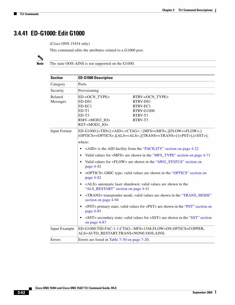
Chapter 3 TL1 Command DescriptionsTL1 Commands
3.4.41 ED-G1000: Edit G1000(Cisco ONS 15454 only)
This command edits the attributes related to a G1000 port.
Note The state OOS-AINS is not supported on the G1000.
Section ED-G1000 Description
Category Ports
Security Provisioning
Related Messages
ED-<OCN_TYPE> RTRV-<OCN_TYPE>ED-DS1 RTRV-DS1ED-EC1 RTRV-EC1ED-T1 RTRV-G1000ED-T3 RTRV-T1RMV-<MOD2_IO> RTRV-T3RST-<MOD2_IO>
Input Format ED-G1000:[<TID>]:<AID>:<CTAG>:::[MFS=<MFS>,][FLOW=<FLOW>,][OPTICS=<OPTICS>,][ALS=<ALS>,][TRANS=<TRANS>]:[<PST>],[<SST>];
where:
• <AID> is the AID facility from the “FACILITY” section on page 4-22
• Valid values for <MFS> are shown in the “MFS_TYPE” section on page 4-71
• Valid values for <FLOW> are shown in the “AWG_STATUS” section on page 4-42
• <OPTICS> GBIC type; valid values are shown in the “OPTICS” section on page 4-82
• <ALS> automatic laser shutdown; valid values are shown in the “ALS_RESTART” section on page 4-41
• <TRANS> transponder mode; valid values are shown in the “TRANS_MODE” section on page 4-94
• <PST> primary state; valid values for <PST> are shown in the “PST” section on page 4-85
• <SST> secondary state; valid values for <SST> are shown in the “SST” section on page 4-87
Input Example ED-G1000:TID:FAC-1-1:CTAG:::MFS=1548,FLOW=ON,OPTICS=COPPER,ALS=AUTO_RESTART,TRANS=NONE:OOS,AINS;
Errors Errors are listed in Table 7-30 on page 7-20.
3-62Cisco ONS 15454 and Cisco ONS 15327 TL1 Command Guide, R4.0
September 2004

Chapter 3 TL1 Command DescriptionsTL1 Commands
3.4.42 ED-NE-GEN: Edit Network Element GeneralThis command edits the node attributes of the NE.
Notes:
1. Only the IPADDR, IPMASK, DEFRTR, IIOP PORT and node name can be modified with this command.
2. The node name can be a maximum of 20 characters. If the entered name exceeds 20 characters, an IPNV (Node Name Too Long) error message is returned.
3. The feature of setting a timing source has been supported since ONS 15454 R3.2.
4. An existing timing source can be removed by setting the address to 0.0.0.0.
Section ED-NE-GEN Description
Category System
Security Superuser
Related Messages
ALW-MSG-ALL RTRV-HDRAPPLY RTRV-INVCOPY-RFILE RTRV-MAP-NETWORKED-DAT RTRV-NE-GENED-NE-SYNCN RTRV-NE-IPMAPINH-MSG-ALL RTRV-NE-SYNCNINIT-SYS RTRV-TODREPT EVT FXFR SET-TOD
Input Format ED-NE-GEN:[<TID>]::<CTAG>:::[NAME=<NAME>,][IPADDR=<IPADDR>,][IPMASK=<IPMASK>,][DEFRTR=<DEFRTR>,][IIOPPORT=<IIOPPORT>,][NTP=<NTP>];
where:
• <NAME> indicates the node name and is a string
• <IPADDR> indicates the node IP address and is a string
• <IPMASK> indicates the node IP mask and is a string
• <DEFRTR> indicates the node default router and is a string
• <IIOPPORT> indicates the node IIOPPORT and is an integer
• <NTP> indicates the node’s NTP timing origin address and is a string
Input Example ED-NE-GEN:CISCO::123:::NAME=NODENAME,IPADDR=192.168.100.52,IPMASK=255.255.255.0,DEFRTR=192.168.100.1,IIOPPORT=57790,NTP=192.168.100.52;
Errors Errors are listed in Table 7-30 on page 7-20.
3-63Cisco ONS 15454 and Cisco ONS 15327 TL1 Command Guide, R4.0
September 2004

Chapter 3 TL1 Command DescriptionsTL1 Commands
3.4.43 ED-NE-SYNCN: Edit Network Element SynchronizationThis command edits the synchronization attributes of the NE.
Notes:
1. Although mixed mode timing is supported in this release, it is not recommended. See the “Mixed Mode Timing Support” section on page 1-14 for more information.
2. The existing external and line modes have the same functionality in all ONS 15454 3.x releases:
External mode: the node derives its timing from the BITS inputs.
Line mode: the node derives its timing from the SONET line(s).
Mixed mode: the node derives its timing from the BITS input or SONET lines.
Section ED-NE-SYNCN Description
Category Synchronization
Security Provisioning
Related Messages
ALW-MSG-ALL RLS-SYNCNSWAPPLY RTRV-ALM-BITSCOPY-RFILE RTRV-ALM-SYNCNED-BITS RTRV-BITSED-DAT RTRV-COND-BITSED-NE-GEN RTRV-COND-SYNCNED-SYNCN RTRV-HDRINH-MSG-ALL RTRV-INVINIT-SYS RTRV-MAP-NETWORKOPR-SYNCNSW RTRV-NE-GENREPT ALM BITS RTRV-NE-IPMAPREPT ALM SYNCN RTRV-NE-SYNCNREPT EVT BITS RTRV-SYNCNREPT EVT FXFR RTRV-TODREPT EVT SYNCN SET-TOD
Input Format ED-NE-SYNCN:[<TID>]::<CTAG>:::[TMMD=<TMMD>,][SSMGEN=<SSMGEN>,][QRES=<QRES>,][RVRTV=<RVRTV>,][RVTM=<RVTM>];
where:
• <TMMD> is the timing mode; valid values for <TMMD> are shown in the “TIMING_MODE” section on page 4-93
• <SSMGEN> is the SSM message set; valid values for <SSMGEN> are shown in the “SYNC_GENERATION” section on page 4-90
• <QRES> is the quality of the RES; valid values for <QRES> are shown in the “SYNC_QUALITY_LEVEL” section on page 4-90
• <RVRTV> is the revertive mode; valid values for <RVRTV> are shown in the “ON_OFF” section on page 4-79
• <RVTM> is the revertive time; valid values for <RVTM> are shown in the “REVERTIVE_TIME” section on page 4-85
3-64Cisco ONS 15454 and Cisco ONS 15327 TL1 Command Guide, R4.0
September 2004

Chapter 3 TL1 Command DescriptionsTL1 Commands
3.4.44 ED-OCH: Edit Optical ChannelCisco ONS 15454 only for MXP and TXP cards.
This command edits the attributes (service parameters) and state of an OCH facility.
See the “Provisioning Rules for MXP_2.5G_10G and TXP_MR_10G Cards” section on page 1-8 for specific MXP/TXP card provisioning rules.
Input Example ED-NE-SYNCN:CISCO::123:::TMMD=LINE,SSMGEN=GEN1,QRES=ABOVE-PRS,RVRTV=Y,RVTM=8.0;
Errors Errors are listed in Table 7-30 on page 7-20.
Section ED-NE-SYNCN Description (continued)
Section ED-OCH Description
Category DWDM
Security Provisioning
Related Messages
RTRV-OCHRTRV-ALM-OCHRTRV-COND-OCHRST-OCHRMV-OCH
3-65Cisco ONS 15454 and Cisco ONS 15327 TL1 Command Guide, R4.0
September 2004

Chapter 3 TL1 Command DescriptionsTL1 Commands
Input Format ED-OCH:[<TID>]:<AID>:<CTAG>:::[RDIRN=<RDIRN>,][EXPWLEN=<EXPWLEN>,][VOAATTN=<VOAATTN>,][VOAPWR=<VOAPWR>,][CALOPWR=<CALOPWR>,][SFBER=<SFBER>,][SDBER=<SDBER>,][ALSMODE=<ALSMODE>,][ALSRCINT=<ALSRCINT>,][ALSRCPW=<ALSRCPW>,][COMM=<COMM>,][GCCRATE=<GCCRATE>,][OSFBER=<OSFBER>,][OSDBER=<OSDBER>,][DWRAP=<DWRAP>,][FEC=<FEC>,][MACADDR=<MACADDR>,][SYNCMSG=<SYNCMSG>,][SENDDUS=<SENDDUS>,][RLASER=<RLASER>,][SOAK=<SOAK>]:[<PST>],[<SST>];
where:
• <AID> is an access identifier from the “CHANNEL” section on page 4-19
• <RDIRN> applicable in a future release
• <EXPWLEN> applicable in a future release
• <VOAATTN> indicates the value of calibrated attenuation for the VOA. It is expressed in Dbm. The range is -24.0 to +2.0Dbm for MXP/TXP cards. <VOAATTN> is a float
• <VOAPWR> applicable in a future release
• <CALOPWR> applicable in a future release
• <SFBER> identifies the SFBER for the SONET payload; valid values are shown in the “SF_BER” section on page 4-86
• <SDBER> identifies the SDBER for the SONET payload; valid values are shown in the “SD_BER” section on page 4-85
• <ALSMODE> indicates if the Automatic Laser Shutdown is enabled or disabled; valid values are shown in the “ALS_MODE” section on page 4-41
• <ALSRCINT> indicates the ALS recovery interval. Range is 100–300 seconds; <ALSRCINT> is an integer
• <ALSRCPW> indicates the ALS recovery pulse width. The range is 2–100 seconds, in increments of 100ms, e.g. 30.1; <ALSRCPW> is a float
• <COMM> indicates if the GCC or DCC is enabled or disabled. The GCC can be enabled only if the digital wrapper has been enabled for the card. The default is NONE. Valid values are shown in the “COMM_TYPE” section on page 4-46. Rules for a MXP/TXP Client port are; only the DCC can be provisioned, if the termination mode is not transparent and the payload is SONET. On a MXP/TXP DWDM port, the DCC can be enabled only if the G.709 is not enabled and if the payload is SONET and the termination mode is not transparent. On a MXP/TXP DWDM port, the GCC can be enabled if there is no DCC and the G.709 flag is enabled.
• <GCCRATE> indicates the data rate of the GCC traffic. Valid values are shown in the “GCCRATE” section on page 4-69. The default is 192Kbps. For MXP/TXP cards this applies only to the DWDM port. The 576K option is not supported for this release.
• <OSFBER> identifies the SFBER for the OTN level. Applicable only if the G.709 is enabled; valid values are shown in the “SF_BER” section on page 4-86
Section ED-OCH Description (continued)
3-66Cisco ONS 15454 and Cisco ONS 15327 TL1 Command Guide, R4.0
September 2004

Chapter 3 TL1 Command DescriptionsTL1 Commands
Input Format (continued)
• <OSDBER> identifies the SDBER for the OTN level. Applicable only if the G.709 is enabled; valid values are shown in the “SD_BER” section on page 4-85
• <DWRAP> is the G.709 digital wrapper. It is either on or off. The system default is ON. For MXP/TXP, this applies only to the DWDM port. To enable G.709 there should be no GCC on the DWDM port. To disable G.709 there should be no GCC on the DWDM port. The FEC should be turned to off; valid values are shown in the “ON_OFF” section on page 4-79
• <FEC> is the Forward Error Correction. It can be enabled only if the G.709 is turned ON. It is either on or off. The system default is ON. For MXP/TXP this applies only to the DWDM port. The FEC level PM and thresholds apply if the FEC is turned on; valid values are shown in the “ON_OFF” section on page 4-79
• <MACADDR> identifies the MAC address for the 10GE payload; <MACADDR> is a string
• <SYNCMSG> indicates that the facility be enabled to provide the synchronization clock. This does not apply to a TXP card. This applies to an MXP card, only if the payload is SONET and the card termination mode is as follows: TRANSPARENT - All Client ports are available for all timing selections. All Trunk ports are not available. LINE - All ports are available for all-timing selections.
• <SENDDUS> indicates that the facility send out a Do not Use for Sync message. This does not apply to a TXP card. This applies to an MXP card, only if the payload is SONET/SDH and the card termination mode is as follows: TRANSPARENT - All Client ports are available for all timing selections. All Trunk ports are not available.LINE - All ports are available for all-timing selections. Valid values are shown in the “ON_OFF” section on page 4-79
• <RLASER> indicates if the laser should be restarted. This is applicable only if the ALSMODE is not automatic; valid values are shown in the “ON_OFF” section on page 4-79
• <SOAK> OOS-AINS to IS transition soak time as measured in 15–minute intervals. A value of 4 translates to a soak time of one hour. The allowable range is 0–192 intervals (maximum of 48–hours). <SOAK> is an integer
• <PST> primary state; valid values are shown in the “PST” section on page 4-85
• <SST> secondary state; valid values are shown in the “SST” section on page 4-87
Input Example ED-OCH:CISCO:CHAN-6-2:114:::RDIRN=W-E,EXPWLEN=1530.32,VOAATTN=2.5,VOAPWR=7.5,CALOPWR=0,SFBER=1E-5,SDBER=1E-6,ALSMODE=Y,ALSRCINT=30,ALSRCPW=35.1,COMM=DCC,GCCRATE=192K,OSFBER=1E-5,OSDBER=1E-6,DWRAP=Y,FEC=Y,MACADDR=00-0E-AA-BB-CC-DD,SYNCMSG=N,SENDDUS=Y,RLASER=Y,SOAK=10:OOS,AINS;
Errors Errors are listed in Table 7-30 on page 7-20.
Section ED-OCH Description (continued)
3-67Cisco ONS 15454 and Cisco ONS 15327 TL1 Command Guide, R4.0
September 2004

Chapter 3 TL1 Command DescriptionsTL1 Commands
3.4.45 ED-PID: Edit PasswordThis command allows a user to change his or her own password.
The password cannot be null. It will be echoed as clear text as the message is parsed only after the complete message is entered and terminated.
Notes:
1. Passwords are masked for the following security commands: ACT-USER, ED-PID, ENT-USER-SECU and ED-USER-SECU. Access to a TL1 session via any means will have the password masked. The CTC Request History and Message Log will also show the masked commands. When a password-masked command is re-issued by double-clicking the command from CTC Request History, the password will still be masked in the CTC Request History and Message Log. The actual password that was previously issued will be sent to the NE. To use a former command as a template only, single-click the command in CTC Request History. The command will be placed in the Command Request text box, where you can edit the appropriate fields prior to re-issuing it.
2. The password will not appear in the TL1 log on the NE.
3. You must use the ED-USER-SECU command to change the empty password (Superuser CISCO15 default empty password) to a non-empty, valid password. The ED-PID command cannot be used to change the empty password to a valid password.
4. For the ED-PID command:
ED-PID:[TID]:<UID>:[CTAG]::<OLDPID>,<NEWPID>;
the syntax of <OLDPID> is not checked. The <NEWPID> is required to follow Telcordia standards (i.e., 10 characters maximum including 1 letter, 1 number, and any one of the following characters: #, %, or +). The <OLDPID> must match what is in the database.
Section ED-PID Description
Category Security
Security Retrieve
Related Messages
ACT-USERCANCCANC-USERDLT-USER-SECUED-USER-SECUENT-USER-SECUREPT EVT SECURTRV-USER-SECU
3-68Cisco ONS 15454 and Cisco ONS 15327 TL1 Command Guide, R4.0
September 2004

Chapter 3 TL1 Command DescriptionsTL1 Commands
3.4.46 ED-SYNCN: Edit SynchronizationThis command edits the synchronization reference list used to determine the sources for the NE's reference clock and the BITS output clock. For each clock, up to three synchronization sources may be specified (e.g., PRIMARY, SECOND, THIRD).To view or edit the system timing mode, use the RTRV-NE-SYNCN or ED-NE-SYNCN commands.
Note To retrieve/set the timing mode, SSM message Set or Quality of RES information, use the RTRV-NE-SYNCN and ED-NE-SYNCN commands.
Input Format ED-PID:[<TID>]:<UID>:<CTAG>::<OLDPID>,<NEWPID>;
where:
• <UID> is the user identifier and is a string; <UID> is any combination of up to 10 alphanumeric characters
• <OLDPID> is the old password and is a string; <OLDPID> is any combination of up to 10 alphanumeric characters. The syntax of <OLDPID> is not checked for backwards compatibility
• <NEWPID> is the user login password and is a string; <NEWPID> is a minimum of 6, maximum of 10 alphanumeric characters including at least one digit and one special character (%, #, or +)
Note CTC allows <UID> and <PID> of up to 20 characters. The 20 character CTC-entered <UID> and <PID> are not valid TL1 <UID> and <PID>.
Input Example ED-PID:CISCO:UID:123::OLDPWD,NEWPWD;
Errors Errors are listed in Table 7-30 on page 7-20.
Section ED-PID Description (continued)
Section ED-SYNCN Description
Category Synchronization
Security Provisioning
Related Messages
ED-BITS RTRV-ALM-BITSED-NE-SYNCN RTRV-ALM-SYNCNOPR-SYNCNSW RTRV-BITSREPT ALM BITS RTRV-COND-BITSREPT ALM SYNCN RTRV-COND-SYNCNREPT EVT BITS RTRV-NE-SYNCNREPT EVT SYNCN RTRV-SYNCNRLS-SYNCNSW
3-69Cisco ONS 15454 and Cisco ONS 15327 TL1 Command Guide, R4.0
September 2004

Chapter 3 TL1 Command DescriptionsTL1 Commands
3.4.47 ED-T1: Edit T1This command edits the attributes related to a DS1/T1 port.
Notes:
1. This command is not allowed if the card is a protecting card.
2. If sending this command to edit TACC and any other attribute(s), and the port having the cross-connection, the (Parameters Not compatible) error message will be returned.
3. Editing TACC via an ED-xxx command is only allowed when there is no circuit/cross-connection on this port and the port/VT does not have a test access point (TAP or TACC number). Otherwise, an error message (e.g. VT in Use) will be returned.
4. TACC creation will also be denied on the protect ports/cards.
5. The state of the T1 port cannot be changed to IS or OOS if a loopback has been operated upon the line.
Input Format ED-SYNCN:[<TID>]:<AID>:<CTAG>:::[PRI=<PRI>,][SEC=<SEC>,][THIRD=<THIRD>][:];
where:
• <AID> is the synchronization reference to be modified and is from the “SYNC_REF” section on page 4-28
• <PRI> is the primary reference of the synchronization and is the AID from the “SYN_SRC” section on page 4-27
• <SEC> is the secondary reference of the synchronization and is the AID from the “SYN_SRC” section on page 4-27
• <THIRD> is the third reference of the synchronization and is the AID from the “SYN_SRC” section on page 4-27
Input Example ED-SYNCN:BOYES:SYNC-NE:112:::PRI=INTERNAL,SEC=INTERNAL,THIRD=INTERNAL;
Errors Errors are listed in Table 7-30 on page 7-20.
Section ED-SYNCN Description (continued)
Section ED-T1 Description
Category Ports
Security Provisioning
Related Messages
ED-<OCN_TYPE> RTRV-<OCN_TYPE>ED-DS1 RTRV-DS1ED-EC1 RTRV-EC1ED-G1000 RTRV-G1000ED-T3 RTRV-T1RMV-<MOD2_IO> RTRV-T3RST-<MOD2_IO>
3-70Cisco ONS 15454 and Cisco ONS 15327 TL1 Command Guide, R4.0
September 2004

Chapter 3 TL1 Command DescriptionsTL1 Commands
3.4.48 ED-T3: Edit T3This command edits the attributes related to a DS3/T3 port.
Notes:
1. This command is not allowed if the card is a protecting card.
2. Both FMT and Line code are not supported for T3/DS3 facility. They are supported on both the DS3XM and DS3E card. The unframed value of the framing format is only supported on the DS3E facility.
3. If sending this command to edit TACC and any other attribute(s), and the port having the cross-connection or the port/VT has a test access point (TAP or TACC number), the (Parameters Not compatible) error message will be returned.
4. Editing TACC via an ED-xxx command is only allowed when there is no circuit/cross-connection on the port and the port/VT does not have a test access point (TAP or TACC number). Otherwise, an error message (e.g. VT in Use) will be returned.
5. TACC creation will also be denied on the protect ports/cards.
6. The state of the T1 port cannot be changed to IS or OOS if a loopback has been operated upon the line.
Input Format ED-T1:[<TID>]:<AID>:<CTAG>:::[LINECDE=<LINECDE>,][FMT=<FMT>,][LBO=<LBO>,][TACC=<TACC>,][SOAK=<SOAK>]:[<PST>],[<SST>];
where:
• <AID> is the access identifier from the “FACILITY” section on page 4-22
• <LINECDE> is a line code; valid values for <LINECDE> are shown in the “LINE_CODE” section on page 4-70
• <FMT> is a frame format; valid values for <FMT> are shown in the “FRAME_FORMAT” section on page 4-69
• <LBO> is a line build out; valid values for <LBO> are shown in the “LINE_BUILDOUT” section on page 4-70
• <TACC> defines the STS as a test access port with a selected unique TAP number. The TAP number ranges from 0–999. When TACC is 0, the TAP is deleted; <TACC> is an integer.
• <SOAK> OOS-AINS to IS transition soak time as measured in 15 minute intervals, so a value of 4 translates to a soak time of 1 hour. The allowable range is 0–192 intervals (maximum of 48 hours); <SOAK> is an integer
• <PST> primary state; valid values for <PST> are shown in the “PST” section on page 4-85
• <SST> secondary state; valid values for <SST> are shown in the “SST” section on page 4-87
Input Example ED-T1:CISCO:FAC-2-1:1223:::LINECDE=AMI,FMT=ESF,LBO=0-131,TACC=8,SOAK=10:OOS,AINS;
Errors Errors are listed in Table 7-30 on page 7-20.
Section ED-T1 Description (continued)
3-71Cisco ONS 15454 and Cisco ONS 15327 TL1 Command Guide, R4.0
September 2004

Chapter 3 TL1 Command DescriptionsTL1 Commands
Section ED-T3 Description
Category Ports
Security Provisioning
Related Messages
ED-<OCN_TYPE> RTRV-<OCN_TYPE>ED-DS1 RTRV-DS1ED-EC1 RTRV-EC1ED-G1000 RTRV-G1000ED-T1 RTRV-T1RMV-<MOD2_IO> RTRV-T3RST-<MOD2_IO>
Input Format ED-T3:[<TID>]:<AID>:<CTAG>:::[FMT=<FMT>,][LINECDE=<LINECDE>,][LBO=<LBO>,][TACC=<TACC>,][SOAK=<SOAK>]:[<PST>],[<SST>];
where:
• <AID> indicates a facility AID from the “FACILITY” section on page 4-22
• <FMT> is a frame format and the unframed value of the framing format is only supported for the DS3E; valid values for <FMT> are shown in the “DS_LINE_TYPE” section on page 4-61
• <LINECDE> is a line code; valid values for <LINECDE> are shown in the “DS_LINE_CODE” section on page 4-61
• <LBO> is a line buildout; valid values for <LBO> are shown in the “E_LBO” section on page 4-62
• <TACC> defines the STS as a test access port with a selected unique TAP number. The TAP number ranges from 0–999. When TACC is 0, the TAP is deleted; <TACC> is an integer
• <SOAK> OOS-AINS to IS transition soak time as measured in 15 minute intervals, so a value of 4 translates to a soak time of 1 hour. The allowable range is 0–192 intervals (maximum of 48 hours); <SOAK> is an integer
• <PST> primary state; valid values for <PST> are shown in the “PST” section on page 4-85
• <SST> secondary state; valid values for <SST> are shown in the “SST” section on page 4-87
Input Example ED-T3:CISCO:FAC-1-2:123:::FMT=C-BIT,LINECDE=B3ZS,LBO=0-225,TACC=8,SOAK=10:OOS,AINS;
Errors Errors are listed in Table 7-30 on page 7-20.
3-72Cisco ONS 15454 and Cisco ONS 15327 TL1 Command Guide, R4.0
September 2004

Chapter 3 TL1 Command DescriptionsTL1 Commands
3.4.49 ED-TRC-CLNT: Edit Trace ClientThis command edits trace-related attributes on client facilities.
See the “Provisioning Rules for MXP_2.5G_10G and TXP_MR_10G Cards” section on page 1-8 for specific MXP/TXP card provisioning rules.
Section ED-TRC-CLNT Description
Category DWDM
Security Provisioning
Related Messages
RTRV-TRC-CLNTED-DWDMRTRV-DWDMRTRV-CLNT
Input Format ED-TRC-CLNT:[<TID>]:<SRC>:<CTAG>:::[EXPTRC=<EXPTRC>,][TRC=<TRC>,][TRCMODE=<TRCMODE>,]TRCLEVEL=<TRCLEVEL>,[TRCFORMAT=<TRCFORMAT>];
where:
• <SRC> is the AID from the “FACILITY” section on page 4-22 and must not be null
• <EXPTRC> indicates the expected path trace message (OTUK-path,J0-section, for example) contents. The <EXPTRC> is any 64-character string, including the termination CR (carriage return) and LF (line feed). <EXPTRC> is a string and a null value is equivalent to ALL
• <TRC> identifies the path trace message to be transmitted. The TRC is any combination of 64 characters, including the terminating CR and LF. The trace byte (OTUK-path,J0-section, for example) continuously transmits a 64-byte string, one byte at a time. A null value defaults to the NE transmitting null characters (Hex 00). <TRC> is a string and a null value is equivalent to ALL
• <TRCMODE> identifies the trace mode and defaults to the OFF mode; valid values are shown in the “TRCMODE” section on page 4-94 and a null value is equivalent to ALL
• <TRCLEVEL> indicates the level of trace. A null value defaults to J0-Section SONET. This is the only applicable level for the client port. Valid values are shown in the “TRCLEVEL” section on page 4-94 and a null value is equivalent to ALL
• Valid values for <TRCFORMAT> are shown in the “TRCFORMAT” section on page 4-94. A null value is equivalent to ALL
Input Example ED-TRC-CLNT:CISCO:FAC-6-1:10:::EXPTRC= “AAA”,TRC=“AAA”,TRCMODE=MAN,TRCLEVEL=PATH,TRCFORMAT=64-BYTE;
Errors Errors are listed in Table 7-30 on page 7-20.
3-73Cisco ONS 15454 and Cisco ONS 15327 TL1 Command Guide, R4.0
September 2004

Chapter 3 TL1 Command DescriptionsTL1 Commands
3.4.50 ED-TRC-OCH: Edit Trace Optical Channel FacilitiesThe command edits trace-related optical channel facilities.
See the “Provisioning Rules for MXP_2.5G_10G and TXP_MR_10G Cards” section on page 1-8 for specific MXP/TXP card provisioning rules.
Section ED-TRC-OCH Description
Category DWDM
Security Provisioning
Related Messages
RTRV-TRC-OCHRTRV-DWDMED-DWDMRTRV-OCH
Input Format ED-TRC-OCH:[<TID>]:<SRC>:<CTAG>:::[EXPTRC=<EXPTRC>,][TRC=<TRC>,][TRCMODE=<TRCMODE>,]TRCLEVEL=<TRCLEVEL>,[TRCFORMAT=<TRCFORMAT>];
where:
• <SRC> is the AID from the “CHANNEL” section on page 4-19 and must not be null
• <EXPTRC> indicates the expected path trace message (OTUK-path,J0-section, for example) contents. The <EXPTRC> is any 64-character string, including the termination CR (carriage return) and LF (line feed). <EXPTRC> is a string and a null value is equivalent to ALL
• <TRC> identifies the path trace message to be transmitted. The TRC is any combination of 64 characters, including the terminating CR and LF. The trace byte (OTUK-path, J0-section, for example) continuously transmits a 64-byte string, one byte at a time. A null value defaults to the NE transmitting null characters (Hex 00). <TRC> is a string and a null value is equivalent to ALL
• <TRCMODE> identifies the trace mode and defaults to the OFF mode; valid values are shown in the “TRCMODE” section on page 4-94
• <TRCLEVEL> indicates the level of trace. A null value defaults to J0 Section. If G.709 is not enabled and the payload is SONET/SDH, the only applicable level is SONET SECTION, which is the J0 byte. If the G.709 is enabled, the TTI monitoring is allowed on all PATH, and SEC. Valid values are shown in the “TRCLEVEL” section on page 4-94
• Valid values for <TRCFORMAT> are shown in the “TRCFORMAT” section on page 4-94
Input Example ED-TRC-OCH:CISCO:CHAN-6-2:10:::EXPTRC=“AAA”,TRC=“AAA”,TRCMODE=MAN,TRCLEVEL=PATH,TRCFORMAT=64-BYTE;
Errors Errors are listed in Table 7-30 on page 7-20.
3-74Cisco ONS 15454 and Cisco ONS 15327 TL1 Command Guide, R4.0
September 2004

Chapter 3 TL1 Command DescriptionsTL1 Commands
3.4.51 ED-UCP-CC: Edit Unified Control Plane Control Channel(Cisco ONS 15454 only)
This command edits UCP IP control channel attributes.
Notes:
1. If sending this command with invalid data, an IIAC (Status, Invalid Data) error message is returned.
2. If sending this command to provision MTU, CRCMD, or both while the IPCC type is routed (CCTYPE=ROUTED), an IIAC (Routed CC Is Not Allowed to Provision MTU & CRCMD) error message is returned.
Section ED-UCP-CC Description
Category UCP
Security Provisioning
Related Messages
DLT-UCP-CC REPT ALM UCPDLT-UCP-IF REPT EVT UCPDLT-UCP-NBR RTRV-ALM-UCPED-UCP-IF RTRV-COND-UCPED-UCP-NBR RTRV-UCP-CCED-UCP-NODE RTRV-UCP-IFENT-UCP-CC RTRV-UCP-NBRENT-UCP-IF RTRV-UCP-NODEENT-UCP-NBR
Input Format ED-UCP-CC:[<TID>]:<AID>:<CTAG>:::[LOCALIPCC=<LOCALIPCC>,][REMOTEIPCC=<REMOTEIPCC>,][LMPHELLOINT=<LMPHELLOINT>,][LMPHELLODEADINT=<LMPHELLODEADINT>,][MTU=<MTU>,][CRCMD=<CRCMD>][:];
where:
• <AID> indicates an individual IPCC ID; <AID> is the AID from the “IPCC” section on page 4-16
• <LOCALIPCC> indicates the local IP address of the control channel and is a string
• <REMOTEIPCC> indicates the remote IP address of the control channel and is a string
• <LMPHELLOINT> indicates the LMP (line management protocol) interval (in milliseconds) and is an integer. It is the time between hello messages sent by this node.
• <LMPHELLODEADINT> indicates the control channel time-out interval (in milliseconds) by the neighbor if the neighbor does not receive the hello message; <LMPHELLODEADINT> is an integer
• <MTU> indicates the MTU size of this control channel and is an integer
• <CRCMD> indicates the CRC mode for this control channel. It is applicable to IPCCs in SDCC type.Valid values for <CRCMD> are shown in the “UCP_CRC_MODE” section on page 4-97
3-75Cisco ONS 15454 and Cisco ONS 15327 TL1 Command Guide, R4.0
September 2004

Chapter 3 TL1 Command DescriptionsTL1 Commands
3.4.52 ED-UCP-IF: Edit Unified Control Plane Interface(Cisco ONS 15454 only)
This command edits UCP interface attributes.
Note If you send invalid data with this command, an IIAC (Status, Invalid Data) error message is returned.
Input Example ED-UCP-CC:CISCO:CC-9:CTAG:::LOCALIPCC=172.20.209.31,REMOTEIPCC=172.20.209.15,LMPHELLOINT=1,LMPHELLODEADINT=5,MTU=1500,CRCMD=16-BIT;
Errors Errors are listed in Table 7-30 on page 7-20.
Section ED-UCP-CC Description (continued)
Section ED-UCP-IF Description
Category UCP
Security Provisioning
Related Messages
DLT-UCP-CC REPT ALM UCPDLT-UCP-IF REPT EVT UCPDLT-UCP-NBR RTRV-ALM-UCPED-UCP-CC RTRV-COND-UCPED-UCP-NBR RTRV-UCP-CCED-UCP-NODE RTRV-UCP-IFENT-UCP-CC RTRV-UCP-NBRENT-UCP-IF RTRV-UCP-NODEENT-UCP-NBR
Input Format ED-UCP-IF:[<TID>]:<AID>:<CTAG>:::[TNATYPE=<TNATYPE>,][TNAADDR=<TNAADDR>,][CORENETWORKID=<CORENETWORKID>][:];
where:
• <AID> indicates the interface port index of the data link; <AID> is the AID from the “FACILITY” section on page 4-22
• <TNATYPE> indicates the TNA (transport network administered) type; valid values for <TNATYPE> are shown in the “UCP_TNA_TYPE” section on page 4-97
• <TNAADDR> indicates the TNA (transport network administered) IP address and is a string
• <CORENETWORKID> is an integer
Input Example ED-UCP-IF:CISCO:FAC-2-1:CTAG:::TNATYPE=IPV4,TNAADDR=172.20.209.73,CORENETWORKID=9;
Errors Errors are listed in Table 7-30 on page 7-20.
3-76Cisco ONS 15454 and Cisco ONS 15327 TL1 Command Guide, R4.0
September 2004

Chapter 3 TL1 Command DescriptionsTL1 Commands
3.4.53 ED-UCP-NBR: Edit Unified Control Plane Neighbor(Cisco ONS 15454 only)
This command edits a UCP neighbor.
The default value of the node name can be overwritten by the TL1 user to a string in a maximum size of 20 characters. If the node name includes non-identified TL1 characters (e.g. space), the text string format with the double quotes is required.
Example:
ENT-UCP-NBR::NBR-18:CTAG:::NBRIX=18,NODEID=192.168.101.18,NAME=NeibhgorName,NDEN=N,HELLOEN=Y,HELLOINT=5, REFREDEN=Y;
Notes:
1. If this command is sent twice or input with invalid data, a SRQN (Status, Invalid Request) error message is returned.
2. If sending this command without neighbor node name in the “NAME” field, an IIAC (Neighbor Name Cannot Be Empty) error message is returned.
3. If sending this command to set the hello interval while the RSVP hello is disabled, an IIAC (HELLOINT Is Not Allowed If HELLOEN Is Disabled) error message is returned.
Section ED-UCP-NBR Description
Category UCP
Security Provisioning
Related Messages
DLT-UCP-CC REPT ALM UCPDLT-UCP-IF REPT EVT UCPDLT-UCP-NBR RTRV-ALM-UCPED-UCP-CC RTRV-COND-UCPED-UCP-IF RTRV-UCP-CCED-UCP-NODE RTRV-UCP-IFENT-UCP-CC RTRV-UCP-NBRENT-UCP-IF RTRV-UCP-NODEENT-UCP-NBR
3-77Cisco ONS 15454 and Cisco ONS 15327 TL1 Command Guide, R4.0
September 2004

Chapter 3 TL1 Command DescriptionsTL1 Commands
3.4.54 ED-UCP-NODE: Edit Unified Control Plane Node(Cisco ONS 15454 only)
This command edits the UCP node level attributes.
The nodeid is the unique number used to identify the local node in LMP, RSVP messages sent to the neighbors. It defaults to the local ethernet interface address (ISA).
The retry initial interval (in seconds) is used for that have been released by the net work side. This interval has a range of 60 seconds (1 minute) to 1800 seconds (30 minutes), with a default value of 180 seconds.
The retry max interval (in seconds) is used for released circuits. The node will back off exponentially from the initial retry interval to this maximum value of 600 seconds (10 minutes).
The restart time is used to be signaled to neighbors. It indicates the time taken by this node (in seconds) to restart. This timer has a range of 1 second to 10 seconds with a default of 5 seconds.
The recovery time is used to be signaled to neighbors. It indicates the time taken by this node (in seconds) to re-sync path, reservation state with a given neighbor. This timer has a range of 300 seconds (5 minutes) to 1800 seconds (30 minutes) and a default value of 600 seconds (10 minutes).
The transmit interval is used to retransmit un-acknowledged messages. This timer has a range of 1 second to 7 seconds with a default value of 1 second.
Input Format ED-UCP-NBR:[<TID>]:<AID>:<CTAG>:::[NAME=<NAME>,][HELLOEN=<HELLOEN>,][HELLOINT=<HELLOINT>,][REFREDEN=<REFREDEN>][:];
where:
• <AID> indicates an individual neighbor index of the UCP. An available neighbor index will be assigned internally while sending this command without AID; <AID> is the AID from the “NBR” section on page 4-16
• <NAME> indicates the neighbor node name. It defaults to the ASCII representation of the node ID in this command. The default value of this node name can be overwritten by the TL1 user to a string in a maximum size of 20 characters. If the node name includes non-identified TL1 characters (e.g. space), the text string format with the double quotes is required. Node name is a string. The default value is “defaults to the nodeid ASCII representation”. <NAME> is a string. The default value is “the ASCII representation of the nodeid”. <NAME> is a string
• <HELLOEN> indicates if the RSVP hello enabled to this neighbor or not; valid values for <HELLOEN> are shown in the “ON_OFF” section on page 4-79
• <HELLOINT> indicates the interval between hello messages to neighbor; <HELLOINT> is an integer
• <REFREDEN> indicates if the refresh reduction is enabled or not; valid values for <REFREDEN> are shown in the “ON_OFF” section on page 4-79
Input Example ED-UCP-NBR:CISCO:NBR-8:CTAG:::NAME=NODE-B,HELLOEN=Y,HELLOINT=20,REFREDEN=N;
Errors Errors are listed in Table 7-30 on page 7-20.
Section ED-UCP-NBR Description (continued)
3-78Cisco ONS 15454 and Cisco ONS 15327 TL1 Command Guide, R4.0
September 2004
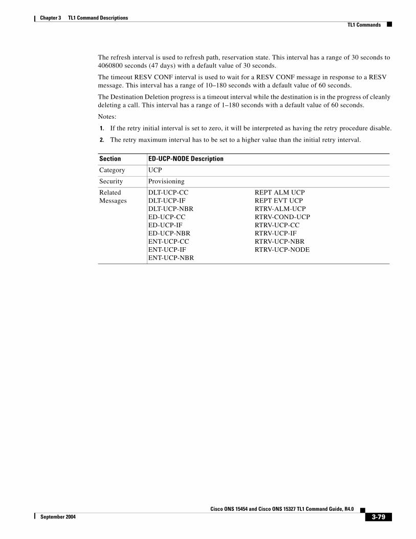
Chapter 3 TL1 Command DescriptionsTL1 Commands
The refresh interval is used to refresh path, reservation state. This interval has a range of 30 seconds to 4060800 seconds (47 days) with a default value of 30 seconds.
The timeout RESV CONF interval is used to wait for a RESV CONF message in response to a RESV message. This interval has a range of 10–180 seconds with a default value of 60 seconds.
The Destination Deletion progress is a timeout interval while the destination is in the progress of cleanly deleting a call. This interval has a range of 1–180 seconds with a default value of 60 seconds.
Notes:
1. If the retry initial interval is set to zero, it will be interpreted as having the retry procedure disable.
2. The retry maximum interval has to be set to a higher value than the initial retry interval.
Section ED-UCP-NODE Description
Category UCP
Security Provisioning
Related Messages
DLT-UCP-CC REPT ALM UCPDLT-UCP-IF REPT EVT UCPDLT-UCP-NBR RTRV-ALM-UCPED-UCP-CC RTRV-COND-UCPED-UCP-IF RTRV-UCP-CCED-UCP-NBR RTRV-UCP-IFENT-UCP-CC RTRV-UCP-NBRENT-UCP-IF RTRV-UCP-NODEENT-UCP-NBR
3-79Cisco ONS 15454 and Cisco ONS 15327 TL1 Command Guide, R4.0
September 2004

Chapter 3 TL1 Command DescriptionsTL1 Commands
Input Format ED-UCP-NODE:[<TID>]::<CTAG>:::[NODEID=<NODEID>,][INITRETRY=<INITRETRY>,][MAXRETRY=<MAXRETRY>,][RESTARTTM=<RESTARTTM>,][RECOVTM=<RECOVTM>,][RXMTINT=<RXMTINT>,][RFRSHINT=<RFRSHINT>,][RESVTIMEOUT=<RESVTIMEOUT>,][RESVCONFTIMEOUT=<RESVCONFTIMEOUT>,][SOURCEDIP=<SOURCEDIP>,][DESTINATIONDIP=<DESTINATIONDIP>][:];
where:
• <NODEID> indicates the node IP address and is a string
• <INITRETRY> indicates the circuit retry initial interval (in seconds) and is an integer
• <MAXRETRY> indicates the circuit maximum retry initial interval (in seconds) and is an integer
• <RESTARTTM> indicates the restart time taken by this local node; <RESTARTTM> is an integer and the default value is 5 seconds.
• <RECOVTM> indicates the circuit retry maximum interval (in seconds) and is an integer
• <RXMTINT> indicates the interval for re-transmitting un-acknowledged messages and is an integer
• <RFRSHINT> indicates the interval for refreshing path, reservation state and is an integer
• <RESVTIMEOUT> indicates the timeout interval for waiting for a reservation message in response to a PATH message; <RESVTIMEOUT> is an integer
• <RESVCONFTIMEOUT> indicates the timeout interval for waiting for a RESV CONF message in response to a RESV message; <RESVCONFTIMEOUT> is an integer
• <SOURCEDIP> indicates the timeout interval of the SourceDip (Source Deletion in Progress) while the source is in the process of cleanly deleting a call; <SOURCEDIP> is an integer
• <DESTINATIONDIP> indicates the timeout interval of the DestinationDip (Destination Deletion in Progress) while the destination is in the process of cleanly deleting a call; <DESTINATIONDIP> is an integer
Input Example ED-UCP-NODE:CISCO::CTAG:::NODEID=192.168.100.52,INITRETRY=180,MAXRETRY=600,RESTARTTM=5,RECOVTM=600,RXMTINT=1,RFRSHINT=30,RESVTIMEOUT=60,RESVCONFTIMEOUT=60,SOURCEDIP=60,DESTINATIONDIP=60;
Errors Errors are listed in Table 7-30 on page 7-20.
Section ED-UCP-NODE Description (continued)
3-80Cisco ONS 15454 and Cisco ONS 15327 TL1 Command Guide, R4.0
September 2004

Chapter 3 TL1 Command DescriptionsTL1 Commands
3.4.55 ED-USER-SECU: Edit User SecurityThis command edits a user's privileges, password, or ID. Only a Superuser may perform this operation. Privilege levels are described in the ENT-USER-SECU command.
Notes:
1. Passwords are masked for the following security commands: ACT-USER, ED-PID, ENT-USER-SECU and ED-USER-SECU. Access to a TL1 session via any means will have the password masked. The CTC Request History and Message Log will also show the masked commands. When a password-masked command is re-issued by double-clicking the command from CTC Request History, the password will still be masked in the CTC Request History and Message Log. The actual password that was previously issued will be sent to the NE. To use a former command as a template only, single-click the command in CTC Request History. The command will be placed in the Command Request text box, where you can edit the appropriate fields prior to re-issuing it.
2. The <UID> can be any combination of up to 10 alphanumeric characters.
3. The <PID> is a string of up to 10 characters where at least 2 are non-alphabetic with at least one special character (+, %, or #).
4. Although the CTC allows both <UID> and <PID> of up to 20 characters, the CTC-entered users (<UID>, <PID>) are not valid TL1 users (e.g., if issuing an ACT-USER command and using the CTC-entered <UID> that is greater than 10 characters long, TL1 will respond with DENY.
5. For the ED-USER-SECU command;
ED-USER-SECU:[TID]:<UID>:[CTAG]::[<NEWUID>],[<NEWPID>],,[<UAP>]:;
a. The syntax of <NEWPID> is checked.
b. If the <NEWPID> is specified, the syntax is checked.
c. The syntax of <UID> is not checked.
d. Old users can change their password without changing their userid, but the new password must meet the new requirements.
e. The <NEWPID> is required when changing the <USERID>.
Currently, when <NEWUID> is specified, <NEWPID> is not optional; however, it is possible to change a userid without changing the password by providing the same password. Users are not allowed to keep their old password if the old password does not meet the new syntax requirements; for example,
<USERID> = DODI2345 <PASSWORD> = DODI#234 /*PASSWORD ALREADY MEETS REQUIREMENTS*/
> ED-USER-SECU::DODI2345:1::DODI3456,DODI#234,,PROV;ED-USER-SECU::DODI2345:1::DODI3456,DODI#234,,PROV;
TCCP 1970-01-02 13:15:35 M 1 COMPLD;
<NEWUSERID> = DODI3456<PASSWORD> = DODI#234<USERID> = CISCO40<PASSWORD> = CISCO40 /*PASSWORD DOES NOT MEET REQUIREMENTS*/
3-81Cisco ONS 15454 and Cisco ONS 15327 TL1 Command Guide, R4.0
September 2004

Chapter 3 TL1 Command DescriptionsTL1 Commands
> ED-USER-SECU::CISCO40:1::CISCO40,,PROV; ED-USER-SECU::CISCO40:1::CISCO40,,PROV;
TCCP 1970-01-02 13:14:24M 1 DENY IIFM /* INVALID PASSWORD */;
6. You must use the ED-USER-SECU command to change the empty password (Superuser CISCO15 default empty password) to a non-empty, valid password. The ED-PID command cannot be used to change the empty password to a valid password.
Section ED-USER-SECU Description
Category Security
Security Superuser
Related Messages
ACT-USERCANCCANC-USERDLT-USER-SECUED-PIDENT-USER-SECUREPT EVT SECURTRV-USER-SECU
Input Format ED-USER-SECU:[<TID>]:<UID>:<CTAG>::[<NEWUID>],[<NEWPID>],,[<UAP>][:];
where:
• <UID> is the user identifier and is a string. The minimum <UID> size is 6, the maximum UID size is 10
• <NEWUID> is the new user identifier and is a string. The minimum <UID> size is 6, the maximum PID size is 10
• <NEWPID> is a new password and is a string; <NEWPID> is a minimum of 6, maximum of 10 alphanumeric characters including at least one digit and one special character (%, #, or +).
• <UAP> is a user access privilege; valid values for <UAP> are shown in the “PRIVILEGE” section on page 4-83
Note CTC allows <UID> and <PID> of up to 20 characters. The 20 character CTC-entered <UID> and <PID> are not valid TL1 <UID> and <PID>.
Input Example ED-USER-SECU:PETALUMA:CISCO15:123::NEWUID,NEWPID,,MAINT;
Errors Errors are listed in Table 7-30 on page 7-20.
3-82Cisco ONS 15454 and Cisco ONS 15327 TL1 Command Guide, R4.0
September 2004

Chapter 3 TL1 Command DescriptionsTL1 Commands
3.4.56 ED-VT1: Edit Virtual TributaryThis command edits the attributes associated with a VT1 path.
Both RVRTV and RVTM parameters only apply to path protection configuration.
The TACC parameter edits an existing single STS or VT and changes it to a test access point. When an editing command on TACC is executed, it assigns the STS for the first 2-way connection and STS=1 as the second 2-way connection.
Error conditions:
1. Sending this command to edit RVRTV or RVTM for the non-path protection configuration VT path, an error message will be returned.
2. If sending this command to edit both TACC and any other attribute(s), the (Parameters Not compatible) error message will be returned.
3. This command is only allowed whenever there are no circuits/cross-connections (no path protection configuration connections) on that AID.
4. If sending this command to edit TACC on an AID with circuits or cross-connections, or if the port/VT has a test access point (TAP or TACC number), an error message (e.g., VT in Use) will be returned.
5. TACC creation will also be denied on the protect ports/cards.
6. TACC creation is allowed on PCA for two-fiber and four-fiber BLSR.
7. TACC is not supported on G1000/MXP/TXP/ML1000-2 and ML100T-12 cards.
Section ED-VT1 Description
Category STS and VT Paths
Security Provisioning
Related Messages
RTRV-VT1
Input Format ED-VT1:[<TID>]:<SRC>:<CTAG>:::[RVRTV=<RVRTV>,][RVTM=<RVTM>,][HOLDOFFTIMER=<HOLDOFFTIMER>,][TACC=<TACC>]:[<PST>],[<SST>];
where:
• <SRC> is an access identifier from the “VT1_5” section on page 4-30
• <RVRTV> identifies revertive mode which only applies to path protection configuration; valid values for <RVRTV> are shown in the “ON_OFF” section on page 4-79
• <RVTM> identifies revertive time; valid values for <RVTM> are shown in the “REVERTIVE_TIME” section on page 4-85
• <HOLDOFFTIMER> is an integer
• <TACC> is the AID from the “TACC” section on page 4-29
• <PST> primary state; valid values for <PST> are shown in the “PST” section on page 4-85
• <SST> secondary state; valid values for <SST> are shown in the “SST” section on page 4-87
3-83Cisco ONS 15454 and Cisco ONS 15327 TL1 Command Guide, R4.0
September 2004

Chapter 3 TL1 Command DescriptionsTL1 Commands
3.4.57 ENT-BLSR: Enter BLSRThis command creates either a two-fiber or four-fiber BLSR.
On successful creation of the BLSR, all cross-connections using the protection bandwidth of the BLSR will be automatically converted to PCA cross-connections.
<RINGID> defaults to AID number (# in the AID format of BLSR-#)
Input examples:
Four-fiber BLSR:
ENT-BLSR:PETALUMA:BLSR-2:123:::RINGID=2,NODEID=3,MODE=4F,RVRTV=Y,RVTM=5.0,SRVRTV=Y,SRVTM=5.0,EASTWORK=FAC-5-1,WESTWORK=FAC-6-1,EASTPROT=FAC-12-1,WESTPROT=FAC-13-1:;
Two-fiber BLSR:
ENT-BLSR:PETALUMA:BLSR-4:123:::RINGID=4,NODEID=6,MODE=2F,RVRTV=Y,RVTM=5.0,EASTWORK=FAC-5-1,WESTWORK=FAC-6-1:;
Error conditions:
1. If the system fails on getting IOR, a SDBE (Status, Internal Data Base Error) error message is returned.
2. If the NE returns nothing for the required BLSR (BLSR-# AID), a SRQN (Status, Invalid Request) error message is returned.
3. In RINGID is different from the AID number, a SDNC (Status, Input Ringid Is Not Consistent with NE Data) error message is returned.
4. Both <EASTPROT> and <WESTPROT> are optional, but required for 4-fiber BLSR creation.
5. Four-fiber BLSR is only supported on OC48 and OC192 cards. Two-fiber BLSR is only supported on OC12, OC48 and OC192 cards. Any attempt to create a BLSR on any other card combination results in a “BLSR Creation Failed” error message.
6. If sending this command to create 4-fiber BLSR on OC12 cards, or 2-fiber BLSR on OC3 cards, an IIAC (Input, Invalid work/prot port) error message will be returned.
7. If sending this command to create a BLSR on an NE that already has two BLSRs, a SRQN (BLSR Creation Failed) error message will be returned because one NE is only allowed to have two BLSRs in this release.
8. If sending this command to create a BLSR on a port with 1+1,a SRQN (BLSR Creation Failed) error message will be returned.
Input Example ED-VT1:CISCO:VT1-2-1-3-1-4:123:::RVRTV=Y,RVTM=1.0,HOLDOFFTIMER=2000,TACC=8:OOS,AINS;
Errors Errors are listed in Table 7-30 on page 7-20.
Section ED-VT1 Description (continued)
Section ENT-BLSR Description
Category BLSR
Security Provisioning
3-84Cisco ONS 15454 and Cisco ONS 15327 TL1 Command Guide, R4.0
September 2004

Chapter 3 TL1 Command DescriptionsTL1 Commands
Related Messages
DLT-BLSR RTRV-ALM-RINGED-BLSR RTRV-BLSRREPT ALM RING RTRV-COND-RINGREPT EVT RING
Input Format ENT-BLSR:[<TID>]:<AID>:<CTAG>:::[RINGID=<RINGID>,]NODEID=<NODEID>,MODE=<MODE>,[RVRTV=<RVRTV>,][RVTM=<RVTM>,][SRVRTV=<SRVRTV>,][SRVTM=<SRVTM>,]EASTWORK=<EASTWORK>,WESTWORK=<WESTWORK>,[EASTPROT=<EASTPROT>,][WESTPROT=<WESTPROT>];
where:
• <AID> identifies the BLSR of the NE. “ALL” or “BLSR-ALL” AID is not allowed for editing BLSR. This command only supports a single BLSR AID. <AID> is the AID from the “BLSR” section on page 4-18
• <RINGID> identifies the BLSR ring ID of the NE. It ranges from 0–9999. <RINGID> is an integer and the default value is “# of AID BLSR-#”
• <NODEID> identifies the BLSR node ID of the NE and is an integer. It ranges from 0–31
• <MODE> identifies the BLSR mode; valid values for <MODE> are shown in the “BLSR_MODE” section on page 4-42
• <RVRTV> identifies the revertive mode and defaults to Y (revertive mode). Valid values for <RVRTV> are shown in the “ON_OFF” section on page 4-79. The default value is Y.
• <RVTM> identifies the revertive time and defaults to 5.0. Valid values for <RVTM> are shown in the “REVERTIVE_TIME” section on page 4-85; the default value is 5.0
• <SRVRTV> identifies the span revertive mode for 4-fiber BLSR only. <SRVRTV> defaults to Y (revertive mode); valid values are shown in the “ON_OFF” section on page 4-79. The default value is Y.
• <SRVTM> identifies the span revertive time for 4-fiber BLSR only. <SRVTM> defaults to 5.0 and valid values are shown in the “REVERTIVE_TIME” section on page 4-85. The default value is 5.0
• <EASTWORK> identifies the east working facility and is the AID from the “FACILITY” section on page 4-22
• <WESTWORK> identifies the west working facility and is the AID from the “FACILITY” section on page 4-22
• <EASTPROT identifies the east protecting facility and is the AID from the “FACILITY” section on page 4-22
• <WESTPROT> identifies the west protecting facility and is the AID from the “FACILITY” section on page 4-22
Input Example ENT-BLSR:PETALUMA:BLSR-2:123:::RINGID=2,NODEID=1,MODE=4F,RVRTV=Y,RVTM=5.0,SRVRTV=Y,SRVTM=5.0,EASTWORK=FAC-5-1,WESTWORK=FAC-6-1,EASTPROT=FAC-12-1,WESTPROT=FAC-13-1;
Errors Errors are listed in Table 7-30 on page 7-20.
Section ENT-BLSR Description (continued)
3-85Cisco ONS 15454 and Cisco ONS 15327 TL1 Command Guide, R4.0
September 2004

Chapter 3 TL1 Command DescriptionsTL1 Commands
3.4.58 ENT-CRS-<STS_PATH>: Enter Cross Connection (STS1, STS3C, STS6C, STS9C, STS12C, STS24C, STS48C, STS192C)
See Table 4-11 on page 4-6 for supported modifiers by platform.
This command creates an STS cross-connection with a cross-connection type (CCT).
When a path protection configuration cross-connection is created, the path presented by the first AID is configured to be the preferred path. For example, the AID (F1) of the cross-connection (created by ENT-CRS-STS1::F1&F2,T1:123;) is the preferred path.
Notes:
1. The default cross-connection type is 2-way
2. If a path is already in a connection, it cannot be in another connection even if the other is a 1-way and the new one will be 1-way the other direction.
3. This command does not support creating multiple STS cross-connections.
4. The path protection configuration cross STS connection can be created by using “&” in the AID fields of this command.
a. The following command is used to create a 1-way selector or 2-way selector and bridge with:
from points: F1, F2
to points: T1
ENT-CRS-{STS_PATH}:[<TID>]:F1&F2,T1:<CTAG>::[<CCT>];
b. The following command is used to create a 1-way bridge or 2-way selector and bridge with:
from point: F1
to points: T1, T2
ENT-CRS-{STS_PATH}:[<TID>]:F1,T1&T2:<CTAG>::[<CCT>];
c. The following command is used to create a 1-way subtending path protection configuration connection or 2-way subtending path protection configuration connection with:
from point: F1, F2
to points: T1, T2
ENT-CRS-{STS_PATH}:[<TID>]:F1&F2,T1&T2:<CTAG>::[<CCT>];
d. The following command is used to create a 2-way selector and bridge with:
from point: F1,F2 (F1 is the working side, F2 is the protect side)
selector points: S1, S2 (S1 is the working side, S2 is the protect side)
ENT-CRS-{STS_PATH}:[<TID>]:F1&F2,S1&S2:<CTAG>::2WAY;
e. The following command is used to create a path protection configuration IDRI Cross-Connection:
ENT-CRS-{STS_PATH}:[<TID>]:A&B,C&D:<CTAG>::2WAYDC;
A–Path on ring X to which traffic from ring Y is bridged
B–Path on ring X to which traffic from the same ring is bridged
C–Path on ring Y to which traffic from ring X is bridged
D–Path on ring Y to which traffic from the same ring is bridged
3-86Cisco ONS 15454 and Cisco ONS 15327 TL1 Command Guide, R4.0
September 2004

Chapter 3 TL1 Command DescriptionsTL1 Commands
A, B, C, and D have a positional meaning. Connection type 2WAYDC is used for path protection configuration IDRI cross-connections.
f. The following command is used to create a path protection configuration DRI Cross-Connection:
ENT-CRS-{STS_PATH}:[<TID>]:A&B,C:<CTAG>::2WAYDC;
A–Path on ring X to which traffic from ring Y is bridged
B–Path on ring X to which traffic from the same ring is bridged
C–Traffic to and from ring Y
A, B, C, and D have a positional meaning. Connection type 2WAYDC is used for path protection configuration DRI cross-connections.
5. All A&B AIDs in the TL1 cross-connection command are in the format of WorkingAID&ProtectAID.
6. To establish a cross-connection on a 2-fiber protection path or on a 4-fiber protection channel, the PCA connection type (1WAYPCA or 2WAYPCA) is required.
7. If you send a PCA cross-connection type on the non-PCA AIDs, the IIAC error message is returned.
8. If you send a non-PCA cross-connection type on the PCA AIDs, the IIAC error message is returned.
9. The facility AID is only valid on slots holding a G1000-4 card (ONS 15454).
10. The virtual facility AID (VFAC) is only valid on slots holding the ML-series card.
Section ENT-CRS-<STS_PATH> Description
Category Cross Connections
Security Provisioning
Related Messages
DLT-CRS-<STS_PATH>DLT-CRS-VT1ED-CRS-<STS_PATH>ED-CRS-VT1ENT-CRS-VT1RTRV-CRSRTRV-CRS-<STS_PATH>RTRV-CRS-VT1
Input Format ENT-CRS-<STS_PATH>:[<TID>]:<SRC>,<DST>:<CTAG>::[<CCT>]::[<PST>],[<SST>];
where:
• <SRC> is the AID from the “CrossConnectID” section on page 4-14
• <DST> is the AID from the “CrossConnectID” section on page 4-14
• <CCT> identifies the cross-connection type; valid values for <CCT> are shown in the “CCT” section on page 4-45
• <PST> primary state; valid values for <PST> are shown in the “PST” section on page 4-85
• <SST> secondary state; valid values for <SST> are shown in the “SST” section on page 4-87
Input Example ENT-CRS-STS1:BODEGA:STS-5-1-1,STS-12-1-5:116::2WAY::OOS,AINS;
Errors Errors are listed in Table 7-30 on page 7-20.
3-87Cisco ONS 15454 and Cisco ONS 15327 TL1 Command Guide, R4.0
September 2004

Chapter 3 TL1 Command DescriptionsTL1 Commands
3.4.59 ENT-CRS-VT1: Enter STS Cross Connection VT1This command creates a VT1 cross connect. When a path protection configuration cross-connection is created, the path presented by the first AID is configured to be the preferred path.
For example, the first AID (F1) of the cross-connection (created by ENT-CRS-VT1::F1&F2,T1:123;) is the preferred path.
Notes:
1. The default cross-connection type is 2-way.
2. If a path is already in a connection, it cannot be in another connection even if the other is a 1-way and the new one will be 1-way the other direction.
3. This command does not support creating multiple VT cross-connections.
4. The path protection configuration VT cross-connection can be created by using “&” in the AID fields of this command.
a. The following command is used to create a 1-way selector or 2-way selector and bridge with:
from points: F1, F2
to points: T1
ENT-CRS-VT1:[<TID>]:F1&F2,T1:<CTAG>::[<CCT>];
b. The following command is used to create a 1-way bridge or 2-way selector and bridge with:
from point: F1
to points: T1, T2
ENT-CRS-VT1:[<TID>]:F1,T1&T2:<CTAG>::[<CCT>];
c. The following command is used to create a 1-way subtending path protection configuration connection or 2-way subtending path protection configuration connection with:
from point: F1, F2
to points: T1, T2
ENT-CRS-VT1:[<TID>]:F1&F2,T1&T2:<CTAG>::[<CCT>];
d. The following command is used to create a 2-way selector and bridge with:
from points: F1, F2 (F1 is the working side, F2 is the protect side)
selector points: S1, S2 (S1 is the working side, S2 is the protect side)
ENT-CRS-VT1:[<TID>]:F1&F2,S1&S2:<CTAG>::2WAY;
5. All a&b AIDs in the TL1 cross-connection command are in the format of WorkingAID&ProtectAID.
6. To establish a cross-connection on a 2-fiber protection path or on a 4-fiber protection channel, the PCA connection type (1WAYPCA or 2WAYPCA) is required.
7. If you send a PCA cross-connection type on the non-PCA AIDs, an IIAC error message is returned.
8. If you send a non-PCA cross-connection type on the PCA AIDs, an IIAC error message is returned.
9. 1-way monitor cross-connects cannot be created. 1WAYMON value for CCT parameter is not supported. However, such cross-connects can be retrieved through the RTRV-CRS-VT1 and RTRV-CRS commands.
3-88Cisco ONS 15454 and Cisco ONS 15327 TL1 Command Guide, R4.0
September 2004

Chapter 3 TL1 Command DescriptionsTL1 Commands
3.4.60 ENT-EQPT: Enter Equipment This command enters the card type and attributes for a given equipment slot in the NE. It also automatically enters all facilities supported by the card, assigning default values to all facility and path attributes.
The command supports optional parameters: RVTM (revertive time), RVRTV (revertive behavior), PROTID (unique protection ID) and PRTYPE (protection type) for configuring the card in an equipment protection group. PRTYPE can be 1:1 and 1:N. These parameters can only be entered for a working AID. The protect card must already be provisioned before creating the protection group.
1:1 protection involves the odd slot protecting the even slot. The work-protect pair is as follows (2-1, 4-3, 6-5, 16-17, 14-15, 12-13). DS1, DS3, DS3XM, DS3N, DS3E, EC1 and other electrical cards support 1:1 protection. The value of PROTID is the protecting slot and is of the form “slot-x”. This command creates a 1:1 protection group. If the command has the optional parameters for creating a protection group and the protection group cannot be created due to an error condition, provisioning of the equipment fails.
The PROTID slot must be provisioned first.
To create 1:1 with the ENT-EQPT command, the working card should not be provisioned first, so the AID type field should be presented in ENT-EQPT for the AID on this <AID>.
Section ENT-CRS-VT1 Description
Category Cross Connections
Security Provisioning
Related Messages
DLT-CRS-<STS_PATH>DLT-CRS-VT1ED-CRS-<STS_PATH>ED-CRS-VT1ENT-CRS-<STS_PATH>RTRV-CRSRTRV-CRS-<STS_PATH>RTRV-CRS-VT1
Input Format ENT-CRS-VT1:[<TID>]:<FROM>,<TO>:<CTAG>::[<CCT>]::[<PST>],[<SST>];
where:
• <FROM> indicates an identifier at one end of the VT cross connection and is the AID from the “VT1_5” section on page 4-30
• <TO> indicates an identifier at the other end of the VT cross-connection and is the AID from the “VT1_5” section on page 4-30
• <CCT> identifies the cross-connection type; valid values for <CCT> are shown in the “CCT” section on page 4-45
• <PST> primary state; valid values for <PST> are shown in the “PST” section on page 4-85
• <SST> secondary state; valid values for <SST> are shown in the “SST” section on page 4-87
Input Example ENT-CRS-VT1:CISCO:VT1-2-3-7-2,VT1-4-4-5-2:1234::1WAY::OOS,AINS;
Errors Errors are listed in Table 7-30 on page 7-20.
3-89Cisco ONS 15454 and Cisco ONS 15327 TL1 Command Guide, R4.0
September 2004

Chapter 3 TL1 Command DescriptionsTL1 Commands
The following is an example for a 1:1 protection group:
ENT-EQPT:[<TID>]:SLOT-1:<CTAG>::DS1;
ENT-EQPT:[<TID>]:SLOT-2:<CTAG>::DS1:PROTID=SLOT-1,PRTYPE=1-1,RVTM=5.0,RVRTV=Y;
1:N protection is always revertive. For 1:N protection, the protect slot can only be Slot 3 or Slot 15. For a protect card in Slot 3, the working cards can be in any of the slots on Bank A. Slot 15 is for protection in Bank B. A DSXN (DS1N or DS3N) card must be provisioned in the protect slot. A 1:1 protection cannot be upgraded to 1:N protection. This command creates a 1:N protection group or adds a new card to an existing 1:N protection group. Multiple working AIDs can be entered in a protection group.
The following is an example of provisioning a 1:N protection group with the ENT-EQPT command:
ENT-EQPT:[<TID>]:SLOT-3:<CTAG>::DS1N;
ENT-EQPT:[<TID>]:SLOT-2&SLOT-1:<CTAG>::DS1:PROTID=SLOT-3,PRTYPE=1-N;
The following is an example of provisioning a 1:N protection group with the ED-EQPT command:
ENT-EQPT:[<TID>]:SLOT-1&SLOT-2:<CTAG>::DS1;
ENT-EQPT:[<TID>]:SLOT-3:<CTAG>::DS1N;
ED-EQPT:[<TID>]:SLOT-2&SLOT-1:<CTAG>:::PROTID=SLOT-1,PRTYPE=1-N;
If the provisioning fails for some AIDs, PRTL responses will be provided indicating failed AIDs. If the provisioning fails for all the AIDs, a DENY response will be provided. For both CMPLD and PRTL responses on creating protection group query, the protection group has been created for the successful AID(s) query.
The following is an example for 1:N protection. The RVRTV parameter is not valid for 1:N protection.
ENT-EQPT:[<TID]>:SLOT-2:<CTAG>:::PROTID=SLOT-3,PRTYPE=1-N,RVTM=5.0;
Both ENT-EQPT and ED-EQPT commands can provision all working AIDs (1-5) together for 1:N by using listed AIDs.
The ENT-EQPT command provisions a new card and adds it to the protection group. The ED-EQPT command adds the already provisioned cards to the protection group.
Protect AID should already be provisioned for either command because protection group parameters are not supported for the protect AID.
The ENT-EQPT command provisions an equipment successfully on an empty slot if the equipment type is compatible with the slot number. This command can have the optional parameters in the “f” block to provision a card as a working card. It has the effect of adding the protection behavior at the time of provisioning itself. For the protection provisioning to succeed, the protect card should have already been provisioned. Trying to execute ENT-EQPT to provision a protection group on an already provisioned card will result in an error.
An example to provision a 1:1 protection group:
ENT-EQPT::SLOT-1:12::DS3;// provision the protect card
ENT-EQPT::SLOT-2:12::DS3:PROTID=SLOT-1,RVRTV=Y,RVTM=8.0; //provision a card and add it to the protection group.
An example to provision a 1:N protection group:
ENT-EQPT::SLOT-3:12::DS3N;//provision the protect card
ENT-EQPT::SLOT-1:12::DS3:PROTID=SLOT-3,RVTM=7.5,PRTYPE=1-N;//provision a card and add it to protection group.
3-90Cisco ONS 15454 and Cisco ONS 15327 TL1 Command Guide, R4.0
September 2004

Chapter 3 TL1 Command DescriptionsTL1 Commands
Notes:
1. Sending this command to provision a DS3NE card on Slot {1,2,4,5,6,12,13,14,16,or 17}, the DS3E card type is presented.
2. Sending this command to provision a DS3N card on Slot {1,2,4,5,6,12,13,14,16,17}, the DS3 card type is presented.
3. Sending this command to provision a DS1N card on Slot-{1,2,4,5,6,12,13,14,16,17}, the DS1 card type is presented.
Error conditions for creating 1:1 or 1:N protection groups are:
1. AID sent to a non-working slot; the working cards must be in even slots for 1:1 and in the same bank for 1:N and not in Slot 3 or Slot 15 (ONS 15454).
2. Invalid AID chosen for protection slot.
3. Working AID is already in protection group.
4. AID is a protect AID.
5. The protect card has a circuit.
6. The equipment type does not match with the allowed AID.
7. The slot is already provisioned.
8. The protecting slot is not provisioned.
9. Multiple working AIDs for 1:1 protection.
Section ENT-EQPT Description
Category Equipment
Security Provisioning
Related Messages
ALW-SWDX-EQPT REPT ALM EQPTALW-SWTOPROTN-EQPT REPT EVT EQPTALW-SWTOWKG-EQPT RTRV-ALM-EQPTDLT-EQPT RTRV-COND-EQPTED-EQPT RTRV-EQPTINH-SWDX-EQPT SW-DX-EQPTINH-SWTOPROTN-EQPT SW-TOPROTN-EQPTINH-SWTOWKG-EQPT SW-TOWKG-EQPT
3-91Cisco ONS 15454 and Cisco ONS 15327 TL1 Command Guide, R4.0
September 2004

Chapter 3 TL1 Command DescriptionsTL1 Commands
3.4.61 ENT-FFP-<OCN_TYPE>: Enter Facility Protection Group (OC3, OC12, OC48, OC192)
See Table 4-11 on page 4-6 for supported modifiers by platform.
This command creates an optical 1+1 protection.
Notes:
1. Protect AID must not be provisioned with traffic.
2. Work AID can be provisioned with traffic.
3. PROTID is a string and can have a maximum length of 32 characters.
4. In this release, 1+1 provisioning between an OC12-4 card and an OC12 card is allowed but is not correct. This provisioning will not be allowed in a future release.
Input Format ENT-EQPT:[<TID>]:<AID>:<CTAG>::<AIDTYPE>:[PROTID=<PROTID>,][PRTYPE=<PRTYPE>,][RVRTV=<RVRTV>,][RVTM=<RVTM>][:];
where:
• <AID> is an access identifier from the “EQPT” section on page 4-21
• <AIDTYPE> is the AID card type; valid values for <AIDTYPE> are shown in the “EQUIPMENT_TYPE” section on page 4-66
• <PROTID> is the protecting card slot identifier of the protection group and is the AID from the “PRSLOT” section on page 4-16
• <PRTYPE> is the protection group type; valid values for <PRTYPE> are shown in the “PROTECTION_GROUP” section on page 4-84
• <RVRTV> is the revertive mode; valid values for <RVRTV> are shown in the “ON_OFF” section on page 4-79
• <RVTM> is the revertive time; valid values for <RVTM> are shown in the “REVERTIVE_TIME” section on page 4-85
Input Example ENT-EQPT:PETALUMA:SLOT-12:118::DS1:PROTID=SLOT-13,PRTYPE=1-1,RVRTV=Y,RVTM=8.5:;
Errors Errors are listed in Table 7-30 on page 7-20.
Section ENT-EQPT Description (continued)
Section ENT-FFP-<OCN_TYPE> Description
Category SONET Line Protection
Security Provisioning
Related Messages
DLT-FFP-<OCN_TYPE>ED-FFP-<OCN_TYPE>EX-SW-<OCN_BLSR>OPR-PROTNSW-<OCN_TYPE>RLS-PROTNSW-<OCN_TYPE>RTRV-FFP-<OCN_TYPE>RTRV-PROTNSW-<OCN_TYPE>
3-92Cisco ONS 15454 and Cisco ONS 15327 TL1 Command Guide, R4.0
September 2004

Chapter 3 TL1 Command DescriptionsTL1 Commands
3.4.62 ENT-FFP-CLNT: Enter Facility Protection Group ClientThis command creates Y cable protection on client facilities
Notes:
1. A Y cable protection group can be created between the client ports of either two TXP cards or two MXP cards.
2. Y cable protection cannot be part of a regeneration group.
3. Only the working ports can be provisioned with DCC and timing reference (if DCC is present on a card, tat card cannot be a protect card).
4. The cards must have the same payload.
See the “Provisioning Rules for MXP_2.5G_10G and TXP_MR_10G Cards” section on page 1-8 for specific MXP/TXP card provisioning rules.
Input Format ENT-FFP-<OCN_TYPE>:[<TID>]:<WORK>,<PROTECT>:<CTAG>:::[PROTID=<PROTID>,][RVRTV=<RVRTV>,][RVTM=<RVTM>,][PSDIRN=<PSDIRN>][:];
where:
• <WORK> identifies a working port and is the AID from the “FACILITY” section on page 4-22
• <PROTECT> identifies a protection port and is the AID from the “FACILITY” section on page 4-22
• <PROTID> is the protection group identifier (protection group name); <PROTID> defaults to the protecting port AID of the protection group, it is a string and can have a maximum length of 32 characters.
• <RVRTV> identifies a revertive mode and defaults to N (non-revertive mode); valid values for <RVRTV> are shown in the “ON_OFF” section on page 4-79
• <RVTM> identifies a revertive time and defaults to 5.0 minutes; valid values for <RVTM> are shown in the “REVERTIVE_TIME” section on page 4-85
• <PSDIRN> identifies the switching mode and defaults to UNI; valid values for <PSDIRN> are shown in the “UNI_BI” section on page 4-97
Input Example ENT-FFP-OC3:PETALUMA:FAC-2-1,FAC-1-1:1:::PROTID=PROT_NAME,RVRTV=Y,RVTM=1.0,PSDIRN=BI;
Errors Errors are listed in Table 7-30 on page 7-20.
Section ENT-FFP-<OCN_TYPE> Description (continued)
Section ENT-FFP-CLNT Description
Category DWDM
Security Provisioning
3-93Cisco ONS 15454 and Cisco ONS 15327 TL1 Command Guide, R4.0
September 2004

Chapter 3 TL1 Command DescriptionsTL1 Commands
3.4.63 ENT-UCP-CC: Enter Unified Control Plane Control Channel(Cisco ONS 15454 only)
This command creates a UCP IP control channel.
If the CCTYPE is SCCC, the SDCC of the port should be created.
The LMP Hello parameters, CRC mode and MTU can be left NULL. The defaults will be assigned by the node.
The UCP remote cannot be provisioned by the user. The local CCID will be allocated by the node.
Related Messages
RTRV-FFP-CLNTED-FFP-CLNTRTRV-DWDMED-DWDMOPR-PROTNSW-CLNTRLS-PROTNSW-CLNTRTRV-COND-CLNTRTRV-ALM-CLNT
Input Format ENT-FFP-CLNT:[<TID>]:<WORKAID>,<PROTAID>:<CTAG>:::[PROTTYPE=<PROTTYPE>,][PROTID=<PROTID>,][RVRTV=<RVRTV>,][RVTM=<RVTM>,][PSDIRN=<PSDIRN>][:];
where:
• <WORKAID> identifies a working port and is the AID from the “FACILITY” section on page 4-22
• <PROTAID> identifies a protection port and is the AID from the “FACILITY” section on page 4-22
• <PROTTYPE> identifies the type of facility protection; valid values are shown in the “PROTTYPE” section on page 4-84
• <PROTID> protection group identifier (protection group name). Defaults to the protecting port AID of the protection group. Is is a string and can have a maximum length of 32 characters; <PROTID> is a string
• <RVRTV> identifies the revertive mode. Defaults to N (non-revertive mode); valid values are shown in the “ON_OFF” section on page 4-79
• <RVTM> identifies the revertive time. Defaults to 5.0 minutes; valid values are shown in the “REVERTIVE_TIME” section on page 4-85
• <PSDIRN> identifies the switching mode and defaults to UNI. Release 4.0 MXP/TXP cards do not support BI-DIRECTIONAL switching. Valid values for <PSDIRN> are shown in the “UNI_BI” section on page 4-97
Input Example ENT-FFP-CLNT:CISCO:FAC-1-1,FAC-2-1:100:::PROTTYPE=Y-CABLE,PROTID=DC-METRO-1,RVRTV=Y,RVTM=1.0,PSDIRN=BI;
Errors Errors are listed in Table 7-30 on page 7-20.
Section ENT-FFP-CLNT Description (continued)
3-94Cisco ONS 15454 and Cisco ONS 15327 TL1 Command Guide, R4.0
September 2004

Chapter 3 TL1 Command DescriptionsTL1 Commands
If the CCTYPE is routed, the remote IPCC defaults to its neighbor’s nodeID.
Examples:
ENT-UCP-CC::CC-12:CTAG:::NBRIX=1,CCTYPE=SDCC,PORT=FAC-6-1,LOCALCCID=12,LOCALIPCC=172.20.209.73,REMOTEIPCC=192.168.100.18,LMPHELLOINT=2,LMPHELLODEADINT=6,MTU=1500,CRCMD=32-BIT;
ENT-UCP-CC::CC-15:CTAG:::NBRIX=8,CCTYPE=ROUTED,LOCALCCID=15,LOCALIPCC=172.20.209.73,REMOTEIPCC=192.168.100.18,LMPHELLOINT=2,LMPHELLODEADINT=6,MTU=1500,CRCMD=16-BIT;
ENT-UCP-CC::CC-16:CTAG:::NBRIX=8,CCTYPE=ROUTED,LOCALCCID=16,LOCALIPCC=172.20.209.73,LMPHELLOINT=2,LMPHELLODEADINT=6,MTU=1500,CRCMD=16-BIT;
Notes:
1. If this command is sent twice, or input with invalid data, a SRQN (Status, Invalid Request) error message is returned.
2. If sending this command to provision MTU, CRCMD, or both while the IPCC type is routed (CCTYPE=ROUTED), an IIAC (Routed CC Is Not Allowed to Provision MTU and CRCMD) error message is returned.
3. The LMPHELLODEADINT interval has to be larger than the hello interval and is normally set to 3 times the hello interval. Its range is 3 seconds to 30 seconds with a default of 15 seconds.
4. If sending this command to provision a ROUTED IPCC no matter if the neighbor discovery (NDEN) is Enabled or Disabled, the REMOTEIPCC has to be specified by the user with non zeros, otherwise, an error message will be returned.
5. If sending this command to provision an SDCC IPCC while the neighbor discovery (NDEN=Y) is Enabled, the REMOTEIPCC defaults to 0.0.0.0, and the user is not allowed to specify REMOTEIPCC, otherwise, and error message (SROF, Cannot specify Remote IPCC for SDCC-IPCC when ND is enabled) will be returned.
6. If sending this command to provision an SDCC IPCC while the neighbor discovery (NDEN=N) is Disabled, the REMOTEIPCC defaults to its neighbor's node ID (IP address).
7. If sending this command to provision an SDCC IPCC with a complete result, the SDCC of the specified SONET line is created (or enabled) automatically with a DB change reporting (if the DB change report is enabled).
8. If sending this command to provision more than 16 IPCC over one NE, a (Cannot create IPCC. Max. number (16) reached) error message is returned.
Section ENT-UCP-CC Description
Category UCP
Security Provisioning
Related Messages
DLT-UCP-CC REPT ALM UCPDLT-UCP-IF REPT EVT UCPDLT-UCP-NBR RTRV-ALM-UCPED-UCP-CC RTRV-COND-UCPED-UCP-IF RTRV-UCP-CCED-UCP-NBR RTRV-UCP-IFED-UCP-NODE RTRV-UCP-NBRENT-UCP-IF RTRV-UCP-NODEENT-UCP-NBR
3-95Cisco ONS 15454 and Cisco ONS 15327 TL1 Command Guide, R4.0
September 2004

Chapter 3 TL1 Command DescriptionsTL1 Commands
Input Format ENT-UCP-CC:[<TID>]:[<AID>]:<CTAG>:::[NBRIX=<NBRIX>,][CCTYPE=<CCTYPE>,][PORT=<PORT>,][LOCALCCID=<LOCALCCID>,][LOCALIPCC=<LOCALIPCC>,][REMOTCCID=<REMOTECCID>,][REMOTEIPCC=<REMOTEIPCC>,][LMPHELLOINT=<LMPHELLOINT>,][LMPHELLODEADINT=<LMPHELLODEADINT>,][MTU=<MTU>,][CRCMD=<CRCMD>,][TUNMD=<TUNMD>][:];
where:
• <AID> indicates an individual IPCC ID and is the AID from the “IPCC” section on page 4-16. The default value is “local IPCC ID”
• <NBRIX> indicates a neighbor within the local node and is an integer
• <CCTYPE> indicates the type of the control channel; valid values for <CCTYPE> are shown in the “UCP_IPCC_TYPE” section on page 4-97
• <PORT> indicates the port which the control channel is configured, while the CCTYPE is the type of SDCC. <PORT> is the AID from the “FACILITY” section on page 4-22 and the default value is “applicable only if it is SDCC type”
• <LOCALCCID> indicates the local control channel ID and is an integer. The default value is “local UCP node id”
• <LOCALIPCC> indicates the local IP address of the control channel and is a string. The default value is “local node id’s node name”
• <REMOTECCID> indicates the local control channel ID and is an integer. The default value is “zero (0) – undefined until discovery by LMP”
• <REMOTEIPCC> indicates the remote IP address of the control channel and is a string. The default value is “0.0.0.0 – undefined for SDCC IPCC and discovered by LMP”
• <LMPHELLOINT> indicates the LMP (line management protocol) interval (in milliseconds). It is the time between hello messages sent by this node, defaults to 5 (with the range of 1–10). <LMPHELLOINT> is an integer and the default value is “5 seconds – (1–10 seconds)”
• <LMPHELLODEADINT> indicates the control channel time-out interval (in milliseconds) by the neighbor if the neighbor does not receive the hello message, and defaults to 15 (with the range of 3–30). This interval has to be at least as large as the hello interval and is normally set to 3 times the hello interval. It’s range is 3–30 seconds with a default of 15 seconds. <LMPHELLODEADINT> is an integer and it’s default value is “15 seconds – (3–30 seconds)”
• <MTU> indicates the MTU size of this control channel. <MTU> is an integer and it’s default value is “1500 bytes”
• <CRCMD> indicates the CRC mode for this control channel. It is applicable to IPCCs in SDCC type. Valid values for <CRCMD> are shown in the “UCP_CRC_MODE” section on page 4-97
• <TUNMD> indicates the IP Tunneling option. It defaults to disabled and valid values are shown in the “UCP_CC_TUN_MD” section on page 4-96
Section ENT-UCP-CC Description (continued)
3-96Cisco ONS 15454 and Cisco ONS 15327 TL1 Command Guide, R4.0
September 2004
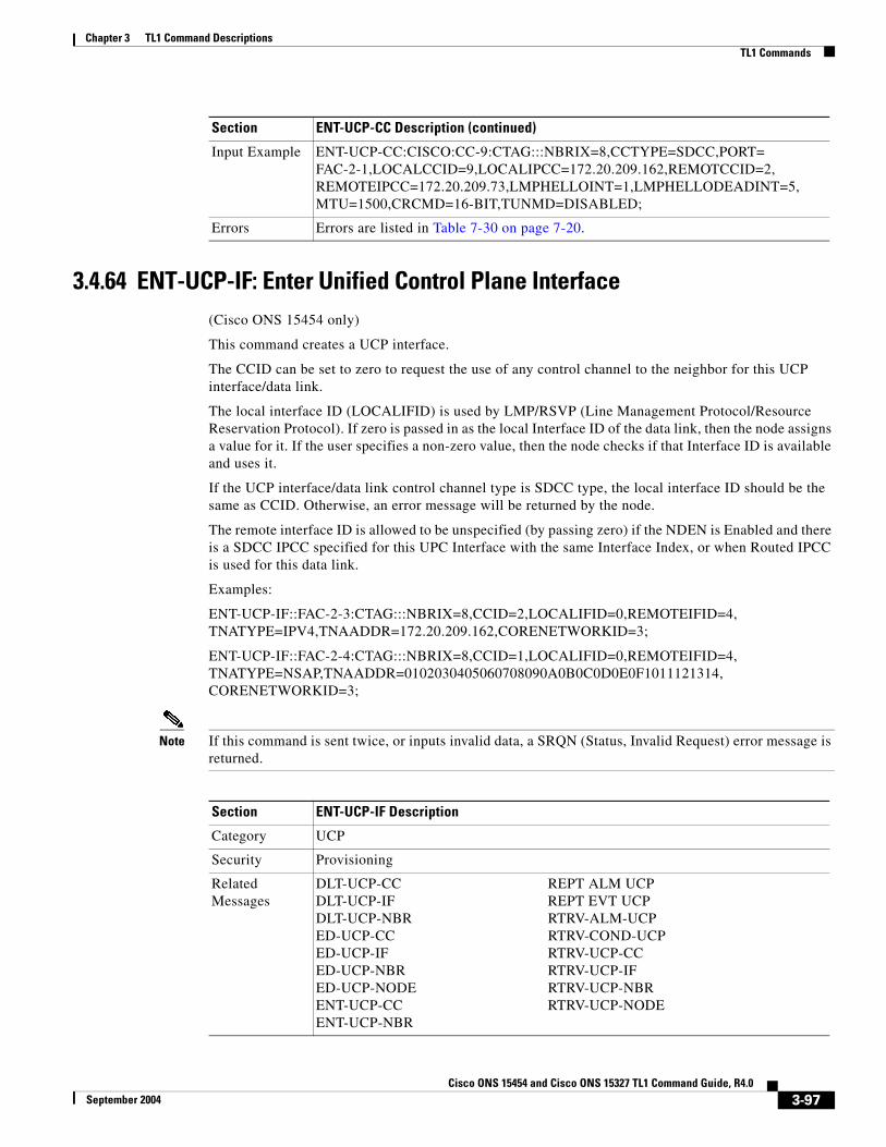
Chapter 3 TL1 Command DescriptionsTL1 Commands
3.4.64 ENT-UCP-IF: Enter Unified Control Plane Interface(Cisco ONS 15454 only)
This command creates a UCP interface.
The CCID can be set to zero to request the use of any control channel to the neighbor for this UCP interface/data link.
The local interface ID (LOCALIFID) is used by LMP/RSVP (Line Management Protocol/Resource Reservation Protocol). If zero is passed in as the local Interface ID of the data link, then the node assigns a value for it. If the user specifies a non-zero value, then the node checks if that Interface ID is available and uses it.
If the UCP interface/data link control channel type is SDCC type, the local interface ID should be the same as CCID. Otherwise, an error message will be returned by the node.
The remote interface ID is allowed to be unspecified (by passing zero) if the NDEN is Enabled and there is a SDCC IPCC specified for this UPC Interface with the same Interface Index, or when Routed IPCC is used for this data link.
Examples:
ENT-UCP-IF::FAC-2-3:CTAG:::NBRIX=8,CCID=2,LOCALIFID=0,REMOTEIFID=4, TNATYPE=IPV4,TNAADDR=172.20.209.162,CORENETWORKID=3;
ENT-UCP-IF::FAC-2-4:CTAG:::NBRIX=8,CCID=1,LOCALIFID=0,REMOTEIFID=4,TNATYPE=NSAP,TNAADDR=0102030405060708090A0B0C0D0E0F1011121314, CORENETWORKID=3;
Note If this command is sent twice, or inputs invalid data, a SRQN (Status, Invalid Request) error message is returned.
Input Example ENT-UCP-CC:CISCO:CC-9:CTAG:::NBRIX=8,CCTYPE=SDCC,PORT=FAC-2-1,LOCALCCID=9,LOCALIPCC=172.20.209.162,REMOTCCID=2,REMOTEIPCC=172.20.209.73,LMPHELLOINT=1,LMPHELLODEADINT=5,MTU=1500,CRCMD=16-BIT,TUNMD=DISABLED;
Errors Errors are listed in Table 7-30 on page 7-20.
Section ENT-UCP-CC Description (continued)
Section ENT-UCP-IF Description
Category UCP
Security Provisioning
Related Messages
DLT-UCP-CC REPT ALM UCPDLT-UCP-IF REPT EVT UCPDLT-UCP-NBR RTRV-ALM-UCPED-UCP-CC RTRV-COND-UCPED-UCP-IF RTRV-UCP-CCED-UCP-NBR RTRV-UCP-IFED-UCP-NODE RTRV-UCP-NBRENT-UCP-CC RTRV-UCP-NODEENT-UCP-NBR
3-97Cisco ONS 15454 and Cisco ONS 15327 TL1 Command Guide, R4.0
September 2004

Chapter 3 TL1 Command DescriptionsTL1 Commands
3.4.65 ENT-UCP-NBR: Enter Unified Control Plane Neighbor(Cisco ONS 15454 only)
This command creates a UCP neighbor.
The default value of the node name can be overwritten by the TL1 user to a string in a maximum size of 20 characters. If the node name includes non-identified TL1 characters (e.g. space), the text string format with the double quotes is required.
Notes:
1. If this command is sent twice or inputs invalid data, a SRQN (Status, Invalid Request) error message is returned.
2. If sending this command without neighbor node name in the “NAME” field, an IIAC (Neighbor Name Can Not be Empty) error message is returned.
3. If sending this command with nodeid while the neighbor discovery is enabled (NDEN=Y), an IIAC (NODEID Is Not Allowed If NDEN Is Enabled) error message is returned.
Input Format ENT-UCP-IF:[<TID>]:<AID>:<CTAG>:::[NBRIX=<NBRIX>,][CCID=<CCID>,][LOCALIFID=<LOCALIFID>,][REMOTEIFID=<REMOTEIFID>,][TNATYPE=<TNATYPE>,][TNAADDR=<TNAADDR>,][CORENETWORKID=<CORENETWORKID>][:];
where:
• <AID> indicates the interface port index of the data link and is the AID from the “FACILITY” section on page 4-22
• <NBRIX> indicates a neighbor within the local node and is an integer
• <CCID> indicates the control channel ID. It can be set to zero to request the use of any control channel to the neighbor for this UCP interface/ data link. <CCID> is an integer. A null value defaults to “any control channel to the neighbor”
• <LOCALIFID> indicates the local interface ID used by LMP/RSVP (Line Management Protocol/Resource reservation Protocol). If this attribute value is assigned by the UI, it will be ignored. <LOCALIFID> is an integer
• <REMOTEIFID> indicates the remote interface ID on the neighbor's side. If this attribute value is passed by UI, it will be ignored. <REMOTEIFID> is an integer
• <TNATYPE> indicates the TNA (Transport Network Administered) type and defaults to IPv4. Valid values for <TNATYPE> are shown in the “UCP_TNA_TYPE” section on page 4-97. The default value is “IPv4”
• <TNAADDR> indicates the TNA (Transport Network Administered) IP address and defaults to IPv4 0.0.0.0. <TNAADDR> is a string. The default value is “0”
• <CORENETWORKID> indicates the core network ID and defaults to one (1). <CORENETWORKID> is an integer and the default value is “1”
Input Example ENT-UCP-IF:CISCO:FAC-2-1:CTAG:::NBRIX=12,CCID=16,LOCALIFID=16,REMOTEIFID=0,TNATYPE=IPV4,TNAADDR=172.20.209.162,CORENETWORKID=7;
Errors Errors are listed in Table 7-30 on page 7-20.
Section ENT-UCP-IF Description (continued)
3-98Cisco ONS 15454 and Cisco ONS 15327 TL1 Command Guide, R4.0
September 2004

Chapter 3 TL1 Command DescriptionsTL1 Commands
4. If sending this command to set the hello interval while the RSVP hello is disabled, an IIAC (HELLOINT Is Not Allowed If HELLOEN Is Disabled) error message is returned.
5. If provisioning a neighbor with disabled neighbor discovery (NDEN=N), and NULL nodeid, a SROF (UCP Neighbor's NodeID cannot be null when Neighbor Discovery is disabled) is returned.
6. If sending this command to create a neighbor with the neighbor node name string longer than 64 characters, an IIAC (Node Name Too Long) error message is returned.
Section ENT-UCP-NBR Description
Category UCP
Security Provisioning
Related Messages
DLT-UCP-CC REPT ALM UCPDLT-UCP-IF REPT EVT UCPDLT-UCP-NBR RTRV-ALM-UCPED-UCP-CC RTRV-COND-UCPED-UCP-IF RTRV-UCP-CCED-UCP-NBR RTRV-UCP-IFED-UCP-NODE RTRV-UCP-NBRENT-UCP-CC RTRV-UCP-NODEENT-UCP-IF
3-99Cisco ONS 15454 and Cisco ONS 15327 TL1 Command Guide, R4.0
September 2004

Chapter 3 TL1 Command DescriptionsTL1 Commands
Input Format ENT-UCP-NBR:[<TID>]:<AID>:<CTAG>:::[NBRIX=<NBRIX>,][NODEID=<NODEID>,]NAME=<NAME>,[NDEN=<NDEN>,][HELLOEN=<HELLOEN>,][HELLOINT=<HELLOINT>,][REFREDEN=<REFREDEN>,][NUMRXMTS=<NUMRXMTS>][:];
where:
• <AID> indicates an individual neighbor index of the UCP. An available neighbor index will be assigned internally while sending this command without AID; <AID> is the AID from the “NBR” section on page 4-16
• <NBRIX> indicates a neighbor within the local node. <NBRIX > is an integer and the default value is “the number of the AID (NBR-#). Or undefined zero (0)”<NODEID> indicates the neighbor node ID as received in RSVP, LMP messages from that node and is a string
• <NAME> indicates the neighbor node name, it has to be specified by the user. If the node name includes non-identified TL1 characters (e.g. space), the text string format with the double quotes is required. <NAME> is a string
• <NDEN> indicates if the neighbor discovery is enabled or not for this neighbor and it defaults to enable (Y). The default value is “Y”. Valid values for <NDEN> are shown in the “ON_OFF” section on page 4-79
• <HELLOEN> indicates if the RSVP hello is enabled to this neighbor or not and defaults to enable (Y). The default value is “Y”. Valid values for <HELLOEN> are shown in the “ON_OFF” section on page 4-79
• <HELLOINT> indicates the interval between hello messages to neighbor and defaults to 5. The default value is “5”. <HELLOINT> is an integer
• <REFREDEN> indicates if the refresh reduction is enabled or not and defaults to enable (Y). The default value is “Y”. Valid values for <REFREDEN> are shown in the “ON_OFF” section on page 4-79
• <NUMRXMTS> indicates the maximum number of retransmits of each message and defaults to 3. The default value is “3”. <NUMRXMTS> is an integer
Input Example ENT-UCP-NBR:CISCO:NBR-8:CTAG:::NBRIX=8,NODEID=192.168.100.52,NAME=NODE-A,NDEN=Y,HELLOEN=Y,HELLOINT=20,REFREDEN=Y,NUMRXMTS=3;
Errors Errors are listed in Table 7-30 on page 7-20.
Section ENT-UCP-NBR Description (continued)
3-100Cisco ONS 15454 and Cisco ONS 15327 TL1 Command Guide, R4.0
September 2004

Chapter 3 TL1 Command DescriptionsTL1 Commands
3.4.66 ENT-USER-SECU: Enter User SecurityThis command adds a user account. Only a Superuser can do this. Each user is configured as being at one of these four privilege levels:
1. Retrieve [RTRV]: Users possessing this security level can retrieve information from the node, but cannot modify anything. The default idle time for Retrieve is unlimited.
2. Maintenance [MAINT]: Users possessing this security level can retrieve information from the node and perform limited maintenance operations such as card resets, Manual/Force/Lockout on cross-connects or in protection groups, and BLSR maintenance. The default idle time for Maintenance is 60 minutes.
3. Provisioning [PROV]: Users possessing this security level can perform all maintenance actions, and all provisioning actions except those restricted to superusers. The default idle time for Provisioning is 30 minutes.
4. Superuser [SUPER]: Users possessing this security level can perform all PROV user actions, plus creating/deleting user security profiles, setting basic system parameters such as time/date, node name, and IP address, doing database backup & restore. The default idle time for Superuser is 15 minutes.
Notes:
1. Passwords are masked for the following security commands: ACT-USER, ED-PID, ENT-USER-SECU and ED-USER-SECU. Access to a TL1 session via any means will have the password masked. The CTC Request History and Message Log will also show the masked commands. When a password-masked command is re-issued by double-clicking the command from CTC Request History, the password will still be masked in the CTC Request History and Message Log. The actual password that was previously issued will be sent to the NE. To use a former command as a template only, single-click the command in CTC Request History. The command will be placed in the Command Request text box, where you can edit the appropriate fields prior to re-issuing it.
2. The <UID> can be any combination of up to 10 alphanumeric characters.
3. The <PID> is a string of up to 10 characters where at least 2 characters are non-alphabetic with at least one special character (+, %, or #).
4. Although the CTC allows both <UID> and <PID> of up to 20 characters, the CTC-entered users (<UID> and <PID>) may not be valid TL1 users (e.g. if issuing an ACT-USER command and using the CTC-entered <UID> that is greater than 10 characters long, TL1 will respond with DENY (Can’t Login) error message.
5. The TL1 password security is enforced as follows:
a. The password <PID> cannot be the same as or contain the userid (UID), for example, if the userid is CISCO25 the password cannot be CISCO25#.
b. The password <PID> must have one non-alphabetic and one special (+, %, or #) character.
c. There is no password <PID> toggling; for example, if the current password is CISCO25#, the new password cannot be CISCO25#
Section ENT-USER-SECU Description
Category Security
Security Superuser
3-101Cisco ONS 15454 and Cisco ONS 15327 TL1 Command Guide, R4.0
September 2004
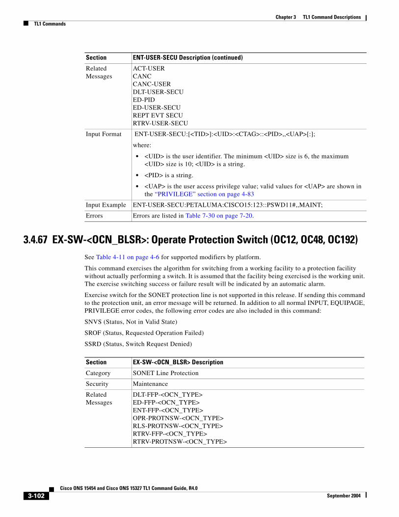
Chapter 3 TL1 Command DescriptionsTL1 Commands
3.4.67 EX-SW-<OCN_BLSR>: Operate Protection Switch (OC12, OC48, OC192)See Table 4-11 on page 4-6 for supported modifiers by platform.
This command exercises the algorithm for switching from a working facility to a protection facility without actually performing a switch. It is assumed that the facility being exercised is the working unit. The exercise switching success or failure result will be indicated by an automatic alarm.
Exercise switch for the SONET protection line is not supported in this release. If sending this command to the protection unit, an error message will be returned. In addition to all normal INPUT, EQUIPAGE, PRIVILEGE error codes, the following error codes are also included in this command:
SNVS (Status, Not in Valid State)
SROF (Status, Requested Operation Failed)
SSRD (Status, Switch Request Denied)
Related Messages
ACT-USERCANCCANC-USERDLT-USER-SECUED-PIDED-USER-SECUREPT EVT SECURTRV-USER-SECU
Input Format ENT-USER-SECU:[<TID>]:<UID>:<CTAG>::<PID>,,<UAP>[:];
where:
• <UID> is the user identifier. The minimum <UID> size is 6, the maximum <UID> size is 10; <UID> is a string.
• <PID> is a string.
• <UAP> is the user access privilege value; valid values for <UAP> are shown in the “PRIVILEGE” section on page 4-83
Input Example ENT-USER-SECU:PETALUMA:CISCO15:123::PSWD11#,,MAINT;
Errors Errors are listed in Table 7-30 on page 7-20.
Section ENT-USER-SECU Description (continued)
Section EX-SW-<OCN_BLSR> Description
Category SONET Line Protection
Security Maintenance
Related Messages
DLT-FFP-<OCN_TYPE>ED-FFP-<OCN_TYPE>ENT-FFP-<OCN_TYPE>OPR-PROTNSW-<OCN_TYPE>RLS-PROTNSW-<OCN_TYPE>RTRV-FFP-<OCN_TYPE>RTRV-PROTNSW-<OCN_TYPE>
3-102Cisco ONS 15454 and Cisco ONS 15327 TL1 Command Guide, R4.0
September 2004

Chapter 3 TL1 Command DescriptionsTL1 Commands
3.4.68 INH-MSG-ALL: Inhibit Message AllThis command inhibits all REPT ALM and REPT EVT autonomous messages from being transmitted. See the ALW-MSG-ALL to resume these autonomous messages. When a TL1 session starts, the REPT ALM and REPT EVT messages are allowed by default.
Note If this command is used twice in the same session, the SAIN (Already Inhibited) error message is reported.
Input Format EX-SW-<OCN_BLSR>:[TID]:<AID>:[CTAG]::[<ST>];
where:
• <AID> identifies the facility in the NE to which the switch request is directed. <AID> is from the “FACILITY” section on page 4-22. <AID> must not be null.
• <ST> is the BLSR switch type. the switch type is optional and for BLSR protection switch only. <ST> defaults to RING switch type and valid values are shown in the “SWITCH_TYPE” section on page 4-89. A null value is equivalent to ALL.
Input Example EX-SW-OC48:CISCO:FAC-12-1:123::SPAN;
Errors Errors are listed in Table 7-30 on page 7-20.
Section EX-SW-<OCN_BLSR> Description (continued)
Section INH-MSG-ALL Description
Category System
Security Retrieve
Related Messages
ALW-MSG-ALL RTRV-HDRAPPLY RTRV-INVCOPY-RFILE RTRV-MAP-NETWORKED-DAT RTRV-NE-GENED-NE-GEN RTRV-NE-IPMAPED-NE-SYNCN RTRV-NE-SYNCNINIT-SYS RTRV-TODREPT EVT FXFR SET-TOD
Input Format INH-MSG-ALL:[<TID>]::<CTAG>[::,,];
Input Example INH-MSG-ALL:PETALUMA::550;
Errors Errors are listed in Table 7-30 on page 7-20.
3-103Cisco ONS 15454 and Cisco ONS 15327 TL1 Command Guide, R4.0
September 2004

Chapter 3 TL1 Command DescriptionsTL1 Commands
3.4.69 INH-MSG-DBCHG: Inhibit Database Change MessageThis command disables REPT DBCHG.
3.4.70 INH-MSG-SECU: Inhibit Message SecurityThis command inhibits the REPT EVT SECU and REPT ALM SECU messages.
3.4.71 INH-PMREPT-ALL: Inhibit Performance Report AllThis command inhibits all scheduled PM reporting. The inhibitance of the PM reporting is session-based, which means the command is only effective to the TL1 session that issues this command. By default, the scheduled PM reporting is inhibited by a TL1 session.
A TL1 session for which PM reports are inhibited will include an INHMSG-PMREPT condition when issuing TL1 command RTRV-COND-ALL.
Section INH-MSG-DBCHG Description
Category Log
Security Retrieve
Related Messages
ALW-MSG-DBCHGREPT DBCHGRTRV-LOG
Input Format INH-MSG-DBCHG:[<TID>]::<CTAG>[::,,];
Input Example INH-MSG-DBCHG:CISCO::123;
Errors Errors are listed in Table 7-30 on page 7-20.
Section INH-MSG-SECU Description
Category Security
Security Superuser
Related Messages
ACT-USER ED-USER-SECUALW-MSG-SECU ENT-USER-SECUCANC REPT EVT SECUCANC-USER REPT EVT SESSIONDLT-USER-SECU RTRV-USER-SECUED-PID
Input Format INH-MSG-SECU:[<TID>]::<CTAG>;
Input Example INH-MSG-SECU:PETALUMA::123;
Errors Errors are listed in Table 7-30 on page 7-20.
Section INH-PMREPT-ALL Description
Category Performance
Security Retrieve
3-104Cisco ONS 15454 and Cisco ONS 15327 TL1 Command Guide, R4.0
September 2004
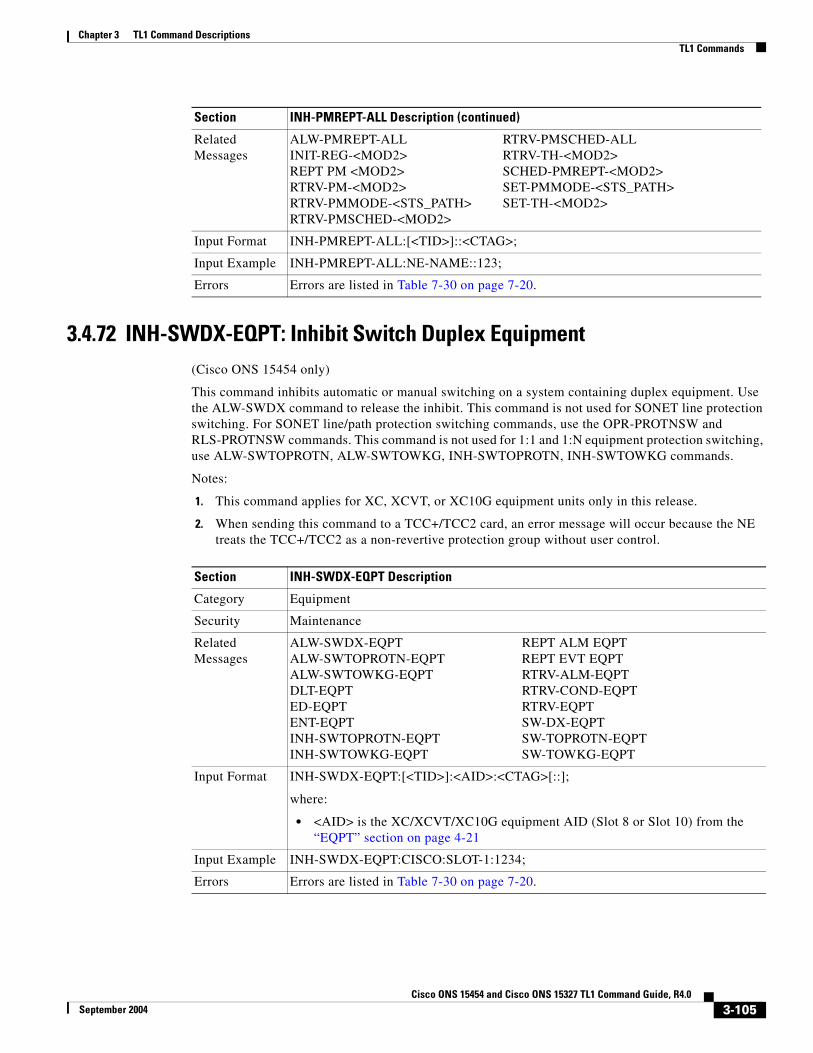
Chapter 3 TL1 Command DescriptionsTL1 Commands
3.4.72 INH-SWDX-EQPT: Inhibit Switch Duplex Equipment(Cisco ONS 15454 only)
This command inhibits automatic or manual switching on a system containing duplex equipment. Use the ALW-SWDX command to release the inhibit. This command is not used for SONET line protection switching. For SONET line/path protection switching commands, use the OPR-PROTNSW and RLS-PROTNSW commands. This command is not used for 1:1 and 1:N equipment protection switching, use ALW-SWTOPROTN, ALW-SWTOWKG, INH-SWTOPROTN, INH-SWTOWKG commands.
Notes:
1. This command applies for XC, XCVT, or XC10G equipment units only in this release.
2. When sending this command to a TCC+/TCC2 card, an error message will occur because the NE treats the TCC+/TCC2 as a non-revertive protection group without user control.
Related Messages
ALW-PMREPT-ALL RTRV-PMSCHED-ALLINIT-REG-<MOD2> RTRV-TH-<MOD2>REPT PM <MOD2> SCHED-PMREPT-<MOD2>RTRV-PM-<MOD2> SET-PMMODE-<STS_PATH>RTRV-PMMODE-<STS_PATH> SET-TH-<MOD2>RTRV-PMSCHED-<MOD2>
Input Format INH-PMREPT-ALL:[<TID>]::<CTAG>;
Input Example INH-PMREPT-ALL:NE-NAME::123;
Errors Errors are listed in Table 7-30 on page 7-20.
Section INH-PMREPT-ALL Description (continued)
Section INH-SWDX-EQPT Description
Category Equipment
Security Maintenance
Related Messages
ALW-SWDX-EQPT REPT ALM EQPTALW-SWTOPROTN-EQPT REPT EVT EQPTALW-SWTOWKG-EQPT RTRV-ALM-EQPTDLT-EQPT RTRV-COND-EQPTED-EQPT RTRV-EQPTENT-EQPT SW-DX-EQPTINH-SWTOPROTN-EQPT SW-TOPROTN-EQPTINH-SWTOWKG-EQPT SW-TOWKG-EQPT
Input Format INH-SWDX-EQPT:[<TID>]:<AID>:<CTAG>[::];
where:
• <AID> is the XC/XCVT/XC10G equipment AID (Slot 8 or Slot 10) from the “EQPT” section on page 4-21
Input Example INH-SWDX-EQPT:CISCO:SLOT-1:1234;
Errors Errors are listed in Table 7-30 on page 7-20.
3-105Cisco ONS 15454 and Cisco ONS 15327 TL1 Command Guide, R4.0
September 2004

Chapter 3 TL1 Command DescriptionsTL1 Commands
3.4.73 INH-SWTOPROTN-EQPT: Inhibit Switch to Protection Equipment(Cisco ONS 15454 only)
This command inhibits automatic or manual switching of an equipment unit to protection. Use the ALW-SWTOPROTN-EQPT command to release the inhibit.
INH-SWTOPROTN-EQPT is used for non-SONET line cards (e.g. DS1, DS3, DS3XM and EC1 cards). DS1 and DS3 cards have 1:1 and 1:N equipment protection. DS3XM and EC1 cards have only 1:1 equipment protection. When performing a lockout with this command, the traffic will be switched from the unit specified by the AID, unless the working unit being protected has failed or is missing. When performing a lock on with this command and the working unit specified in the AID is in standby, sending this command will also initiate a traffic switch. When traffic is locked on a working unit or locked out of the protection unit with this command, the protection unit will not carry traffic, even if the working unit is pulled from the system.
Sending this command to a working unit in a 1:N protection group does not prevent a protection switch from another working unit in the same protection group. All the working units must be sent this command to prevent a protection switch. If the command is sent only to a subset of the working units, only those working units will have traffic locked on.
The inhibit state is persistent over TCC+/TCC2 side switches and removal/reboot of all the units in the protection group. The inhibit state can, but does not have to be persistent over a complete power cycle of the NE.
The unit specified by the AID will raise the condition of INHSWPR when this command is sent.
Notes:
1. This command only supports one value of the <DIRN> parameter - BTH. A command with any other value is considered an incorrect use of the command. An IDNV (Input, Data Not Valid) error message should be responsed.
2. This command is not used for the common control (TCC+/TCC2 or XC/XCVT/XC10G) cards. A command on a common control card will receive an IIAC (Input, Invalid Access Identifier) error message. To use the common control card switching commands, use the SW-DX-EQPT and ALW-SWDX-EQPT commands.
3. This command is not used for SONET (OCN) cards. A command on a SONET card will receive an IIAC (Input, Invalid Access Identifier) error message. To use a SONET card switching command, use the OPR-PROTNSW and RLS-PROTNSW commands.
4. If this command is used on a card that is not in a protection group, the SNVS (Status, Not in Valid State) error message should be received.
5. If this command is used on a card that is already in the inhibit state, the SAIN (Status, Already Inhibited) error message should be received.
6. If sending the inhibit switch to protection command to a working card when the protect card in the same protection group has already raised the condition of INHSWWKG, the SPLD (Status, Protection unit Locked) error message should be responsed.
7. If sending the inhibit switch to protection command to the protect card when a working card in the same protection group has already raised the condition of INHSWWKG, the SWLD (Status, Working unit Locked) error message should be responsed.
8. Sending the inhibit switch to protection command to an active protect card when the peer working card is failed or missing, the SWFA (Status, Working unit Failed) error message should be responsed.
3-106Cisco ONS 15454 and Cisco ONS 15327 TL1 Command Guide, R4.0
September 2004

Chapter 3 TL1 Command DescriptionsTL1 Commands
9. The following situation(s) are allowed and will not generate any error response: sending this command to missing cards as long as none of the previous error conditions apply.
3.4.74 INH-SWTOWKG-EQPT: Inhibit Switch to Working Equipment(Cisco ONS 15454 only)
This command inhibits automatic or manual switching of an equipment unit back to the working unit. Use the ALW-SWTOWKG-EQPT command to release the inhibit.
INH-SWTOWKG-EQPT is used for non-SONET line cards (e.g. DS1, DS3, DS3XM and EC1 cards). DS1 and DS3 cards have 1:1 and 1:N equipment protection. DS3XM and EC1 cards have only 1:1 equipment protection. When performing a lock-out with this command, the traffic will be switched from the unit specified by the AID, unless the protection unit has failed or is missing. When performing a lock-on with this command and the protection unit specified in the AID is in standby, sending this command will initiate a traffic switch only when there is one working card in the protection group. In the case where there is more than one working card in the protection group, an error will be generated (see error conditions below). When traffic is locked on the protection unit or locked out of a working unit with this command, the working unit will not carry traffic, even if the protection unit is pulled from the system.
The inhibit state is persistent over TCC+/TCC2 side switches and removal/reboot of all the units in the protection group. The inhibit state can but does not have to be persistent over a complete power cycle of the NE.
The unit specified by the AID will raise the condition of INHSWWKG when this command is sent.
Section INH-SWTOPROTN-EQPT Description
Category Equipment
Security Maintenance
Related Messages
ALW-SWDX-EQPT REPT ALM EQPTALW-SWTOPROTN-EQPT REPT EVT EQPTALW-SWTOWKG-EQPT RTRV-ALM-EQPTDLT-EQPT RTRV-COND-EQPTED-EQPT RTRV-EQPTENT-EQPT SW-DX-EQPTINH-SWDX-EQPT SW-TOPROTN-EQPTINH-SWTOWKG-EQPT SW-TOWKG-EQPT
Input Format INH-SWTOPROTN-EQPT:[<TID>]:<AID>:<CTAG>[::<DIRN>];
where:
• <AID> This parameter can either be the working unit for which switching to protection is inhibited (lock on) or the protection unit for which carrying traffic is to be inhibited (lockout); <AID> is from the “EQPT” section on page 4-21
• <DIRN> is the direction of the switching. The command only supports one value of the <DIRN> parameter - BTH. This parameter defaults to BTH; valid values for <DIRN> are shown in the DIRECTION, page 60
Input Example INH-SWTOPROTN-EQPT:CISCO:SLOT-2:123::BTH;
Errors Errors are listed in Table 7-30 on page 7-20.
3-107Cisco ONS 15454 and Cisco ONS 15327 TL1 Command Guide, R4.0
September 2004

Chapter 3 TL1 Command DescriptionsTL1 Commands
Notes:
1. The command only supports one value of the <DIRN> parameter - BTH. A command with any other value is considered an incorrect use of the command. An IDNV (Input, Data Not Valid) error message should be responsed.
2. This command is not used for the common control (TCC+/TCC2 or XC/XCVT/XC10G) cards. A command on a common control card will receive an IIAC (Input, Invalid Access Identifier) error message. To use the common control card switching commands, use the SW-DX-EQPT and ALW-SWDX-EQPT commands.
3. This command is not used for SONET (OCN) cards. A command on a SONET card will receive an IIAC (Input, Invalid Access Identifier) error message. To use a SONET card switching command, use the OPR-PROTNSW and RLS-PROTNSW commands.
4. If this command is used on a card that is not in a protection group, the SNVS (Status, Not in Valid State) error message should be received.
5. If this command is used on a card that is already in the inhibit state, the SAIN (Status, Already Inhibited) error message should be received.
6. If sending this command to a working card when the protect card in the same protection group has already raised the condition of INHSWPR, the SPLD (Status, Protection unit Locked) error message should be received.
7. If sending the INH-SWTOWKG command to a protect card when a working card in the same protection group has already raised the condition of INHSWPR, the SWLD (Status, Working unit Locked) error message should be responsed.
8. If sending the INH-SWTOWKG command to an active working card when the protect card has failed or is missing, the SPFA (Status, Protection unit Failed) error message should be received.
9. If sending the INH-SWTOWKG command to an active working card when the protect card is already carrying traffic (this only occurs in a 1:N protection group with N greater than one), the SPAC (Status, Protection unit Active) error message should be received.
10. The following situation is allowed and will not generate any error response: Sending this command to missing cards as long as none of the previous error conditions apply.
Section INH-SWTOWKG-EQPT Description
Category Equipment
Security Maintenance
Related Messages
ALW-SWDX-EQPT REPT ALM EQPTALW-SWTOPROTN-EQPT REPT EVT EQPTALW-SWTOWKG-EQPT RTRV-ALM-EQPTDLT-EQPT RTRV-COND-EQPTED-EQPT RTRV-EQPTENT-EQPT SW-DX-EQPTINH-SWDX-EQPT SW-TOPROTN-EQPTINH-SWTOPROTN-EQPT SW-TOWKG-EQPT
3-108Cisco ONS 15454 and Cisco ONS 15327 TL1 Command Guide, R4.0
September 2004
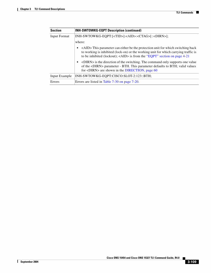
Chapter 3 TL1 Command DescriptionsTL1 Commands
Input Format INH-SWTOWKG-EQPT:[<TID>]:<AID>:<CTAG>[::<DIRN>];
where:
• <AID> This parameter can either be the protection unit for which switching back to working is inhibited (lock-on) or the working unit for which carrying traffic is to be inhibited (lockout); <AID> is from the “EQPT” section on page 4-21
• <DIRN> is the direction of the switching. The command only supports one value of the <DIRN> parameter - BTH. This parameter defaults to BTH; valid values for <DIRN> are shown in the DIRECTION, page 60
Input Example INH-SWTOWKG-EQPT:CISCO:SLOT-2:123::BTH;
Errors Errors are listed in Table 7-30 on page 7-20.
Section INH-SWTOWKG-EQPT Description (continued)
3-109Cisco ONS 15454 and Cisco ONS 15327 TL1 Command Guide, R4.0
September 2004

Chapter 3 TL1 Command DescriptionsTL1 Commands
3.4.75 INIT-REG-<MOD2>: Initialize Register (CLNT, DS1, EC1, OC3, OC12, OC48, OC192, OCH, STS1, STS3C, STS6C, STS9C, STS12C, STS24C, STS48C, STS192C, T1, T3, VT1)
See Table 4-11 on page 4-6 for supported modifiers by platform.
This command initializes the performance monitoring (PM) registers.
Notes:
1. The time period is always the current time period, and the previous time period counts are not cleared; therefore, both <MONDAT> and <MONTM> are not supported in this command.
2. Both transmit and receive directions are allowed in DS1, other cards only support the receive direction.
Section INIT-REG-<MOD2> Description
Category Performance
Security Maintenance
Related Messages
ALW-PMREPT-ALLINH-PMREPT-ALLINIT-REG-G1000REPT PM <MOD2>RTRV-PM-<MOD2>RTRV-PMMODE-<STS_PATH>RTRV-PMSCHED-<MOD2>RTRV-PMSCHED-ALLRTRV-TH-<MOD2>SCHED-PMREPT-<MOD2>SET-PMMODE-<STS_PATH>SET-TH-<MOD2>
Input Format INIT-REG-<MOD2>:[<TID>]:<AID>:<CTAG>::,,[<LOCN>],[<DIRN>],[<TMPER>][,,];
where:
• <AID> is the access identifier. All the STS, VT1, facility and DS1 AIDs are supported; <AID> is from the “ALL” section on page 4-10
• <LOCN> indicates the location, in reference to the entity identified by the AID, valid values for <LOCN> are shown in the “LOCATION” section on page 4-71
• <DIRN> is the direction of PM relative to the entity identified by the AID. <DIRN> defaults to ALL, which means that the command initializes all the registers irrespective of the PM direction. Valid values for <DIRN> are shown in the “DIRECTION” section on page 4-60.
• <TMPER> indicates the accumulation time period for the PM information; valid values for <TMPER> are shown in the “TMPER” section on page 4-93. A null value of <TMPER> defaults to 15-MIN. The default value is 15-MIN.
Input Example INIT-REG-OC3:CISCO:FAC-1-1:1234::,,NEND,BTH,15-MIN;
Errors Errors are listed in Table 7-30 on page 7-20.
3-110Cisco ONS 15454 and Cisco ONS 15327 TL1 Command Guide, R4.0
September 2004

Chapter 3 TL1 Command DescriptionsTL1 Commands
3.4.76 INIT-SYS: Initialize SystemThis command initializes the specified card and its associated subsystem(s).
Notes:
1. The SLOT-ALL AID and the list AID are not allowed in this command.
2. Only one level of restart is supported in this command.
3. It is important that the standby TCC+/TCC2 should be up and running fully standby before this command is sent on the active TCC+/TCC2 for a period of time. During this time, the system is vulnerable to traffic outages caused by timing disruptions or other causes.
3.4.77 OPR-ACO-ALL: Operate Alarm Cutoff AllThis command cuts off the office audible alarm indication without changing the local alarm indications.
This command does not have any effect on future alarms at the NE, it directs the NE to provide conditioning only on those alarms that are currently active.
The ACO retires the Central Office (CO) alarm audible indicators without clearing the indicators that show the trouble still exists. There is no need for a RLS-ACO command.
Section INIT-SYS Description
Category System
Security Maintenance
Related Messages
ALW-MSG-ALL RTRV-HDRAPPLY RTRV-INVCOPY-RFILE RTRV-MAP-NETWORKED-DAT RTRV-NE-GENED-NE-GEN RTRV-NE-IPMAPED-NE-SYNCN RTRV-NE-SYNCNINH-MSG-ALL RTRV-TODREPT EVT FXFR SET-TOD
Input Format INIT-SYS:[<TID>]:<AID>:<CTAG>[::];
where:
• <AID> is the access identifier of the equipment unit or slot and is from the “EQPT” section on page 4-21
Input Example INIT-SYS:HOTWATER:SLOT-8:201;
Errors Errors are listed in Table 7-30 on page 7-20.
Section OPR-ACO-ALL Description
Category Environment Alarms and Controls
Security Maintenance
3-111Cisco ONS 15454 and Cisco ONS 15327 TL1 Command Guide, R4.0
September 2004

Chapter 3 TL1 Command DescriptionsTL1 Commands
3.4.78 OPR-EXT-CONT: Operate External ControlThis command operates an external control and closes the external control contact. The control can be operated momentarily or continuously.
Notes:
1. The duration has two values in this release:
MNTRY: Momentary duration
CONTS: Continuos duration
2. In an automatic state, the contact could be opened or closed depending on the provisioned trigger.
3. RLS-EXT-CONT changes the state to automatic. Therefore, issuing an OPR-EXT-CONT command when the control is manually open and then issuing a RLS-EXT-CONT will not revert the state back to Manual Open.
4. A NULL value for the duration parameter defaults to MNTRY in this release.
5. The RLS-EXT-CONT is not allowed during the MNTRY duration, the command is allowed for the CONTS duration. The length of the MNTRY duration is set to be 2 seconds on Cisco ONS 15454.
Caution Do not turn on external controls that activate a potential danger; such as, sprinklers or other controls connected to possibly hazardous systems or equipment.
Related Messages
OPR-EXT-CONT RTRV-ATTR-ENVREPT ALM ENV RTRV-COND-ENVREPT EVT ENV RTRV-EXT-CONTRLS-EXT-CONT SET-ATTR-CONTRTRV-ALM-ENV SET-ATTR-ENVRTRV-ATTR-CONT
Input Format OPR-ACO-ALL:[<TID>]::<CTAG>;
Input Example OPR-ACO-ALL:CISCO::123;
Errors Errors are listed in Table 7-30 on page 7-20.
Section OPR-ACO-ALL Description (continued)
Section OPR-EXT-CONT Description
Category Environment Alarms and Controls
Security Maintenance
Related Messages
OPR-ACO-ALL RTRV-ATTR-ENVREPT ALM ENV RTRV-COND-ENVREPT EVT ENV RTRV-EXT-CONTRLS-EXT-CONT SET-ATTR-CONTRTRV-ALM-ENV SET-ATTR-ENVRTRV-ATTR-CONT
3-112Cisco ONS 15454 and Cisco ONS 15327 TL1 Command Guide, R4.0
September 2004

Chapter 3 TL1 Command DescriptionsTL1 Commands
3.4.79 OPR-LPBK-<MOD2>: Operate Loopback (CLNT, DS1, EC1, OC12, OC192, OC3, OC48, OCH, STS1, STS12C, STS192C, STS24C, STS3C, STS48C, STS6C, STS9C, T1, T3, VT1)
See Table 4-11 on page 4-6 for supported modifiers by platform.
This command operates a signal loopback on an I/O card or on a cross-connect.
The optional [<LPBKTYPE>] defaults to FACILITY in this command if it is given to a port entity. It defaults to CRS if given to an STS entity.
Notes:
1. The value CRS for the LPBKTYPE parameter is applicable only for the STS modifier. The FACILITY and TERMINAL values are applicable to the ports.
2. The TERMINAL loopback type is not supported for the DS1 line of a DS3XM card.
3. Loopbacks are only allowed to be setup if the port/interface/STS_PATH is in OOS-MT or in OOS-AINS state.
4. Cross-connect loopbacks cannot be applied:
• to the destination end of a 1WAY cross-connects
• to non-optical boards
• to VT1.5
• if a a terminal/facility loopback is already applied
• on a protect card in 1+1 (working mode)
5. A cross-connect loopback can be applied only on one STS path of a cross-connect.
Input Format OPR-EXT-CONT:[<TID>]:<AID>:<CTAG>::[<CONTTYPE>],[<DURATION>];
where:
• <AID> is the access identifier environment AID from the “ENV” section on page 4-20 and must not be null
• <CONTTYPE> is the type of control; valid values for <CONTTYPE> are shown in the “CONTTYPE” section on page 4-59. A null value is equivalent to ALL.
• Valid values for <DUR> are shown in the “DURATION” section on page 4-62. A null value is equivalent to ALL.
Input Example OPR-EXT-CONT:CISCO:ENV-OUT-2:123::AIRCOND,CONTS;
Errors Errors are listed in Table 7-30 on page 7-20.
Section OPR-EXT-CONT Description (continued)
Section OPR-LPBK-<MOD2> Description
Category Testing
Security Maintenance
Related Messages
RLS-LPBK-<MOD2>
3-113Cisco ONS 15454 and Cisco ONS 15327 TL1 Command Guide, R4.0
September 2004

Chapter 3 TL1 Command DescriptionsTL1 Commands
3.4.80 OPR-PROTNSW-<OCN_TYPE>: Operate Protection Switch (OC3, OC12, OC48, OC192)
See Table 4-11 on page 4-6 for supported modifiers by platform.
This command initiates a SONET line protection switch request. User switch requests initiated with this command remain active until they are released via the RLS-PROTNSW-OCN command or are overridden by a higher priority protection switch request.
The switch commands; MAN (Manual Switch), FRCD (Forced Switch) and LOCKOUT (Lockout) are supported by the ONS 15454.
Manual Switch of Protection Line (to Working Line). If the AID identifies the protection line, then (only in the 1+1 architecture) service will be transferred from the protection line to the working line, unless a request of equal or higher priority is in effect.
Manual Switch of Working Line (to Protection Line). If the AID identifies a working line, then service will be switched from the working line to the protection line unless a request of equal or higher priority is in effect.
Force Switch of Protection Line (to Working Line). If the AID identifies the protection line, then (only in the 1+1 architecture) service will be transferred from the protection line to the working line unless a request of equal or higher priority is in effect.
Force Switch of Working Line (to Protection Line). If the AID identifies a working line, then service will be transferred from the working line to the protection line unless a request of equal or higher priority is in effect. A lockout of protection and a signal fail of protection line have higher priority than this switch command.
Lockout of Protection Line. If the AID identifies the protection line, this switch command will prevent the working line from switching to protection line. If the working line is already on protection, then the working line will be switched back to its original working line.
Lockout of Protection Line. If the AID identifies protection line, this switch command will prevent the working line from switching to protection line. If the working line is already on protection, then the working line will be switched back from protection line to its original working line.
Notes:
1. This command is not used for the common control (TCC+/TCC2 or XC/XCVT/XC10G) cards. A query on a common control card will generate an IIAC (Input, Invalid Access Identifier) error message. To use this command on the common control card switching commands, use the SW-DX-EQPT and ALW-SWDX-EQPT commands.
Input Format OPR-LPBK-<MOD2>:[<TID>]:<SRC>:<CTAG>::,,,[<LPBKTYPE>];
where:
• <SRC> is an access identifier from the “DS1” section on page 4-20. Valid values for AID are facility, DS1, and STS.
• <LPBKTYPE> is a loopback type; valid values for <LPBKTYPE> are shown in the “LPBK_TYPE” section on page 4-71
Input Example OPR-LPBK-DS1:PTREYES:DS1-4-1-2-13:203::,,,FACILITY;
Errors Errors are listed in Table 7-30 on page 7-20.
Section OPR-LPBK-<MOD2> Description (continued)
3-114Cisco ONS 15454 and Cisco ONS 15327 TL1 Command Guide, R4.0
September 2004

Chapter 3 TL1 Command DescriptionsTL1 Commands
2. Sending this command on non-SONET (OCN) cards, an IIAC (Input, Invalid Access Identifier) error message should be received. To query on a non-SONET card switching command, use the ALW-SWTOPROTN/SWTOWKG-EQPT and INH-SWTOPROTN/SWTOWKG-EQPT commands.
3. When sending this command to query on a card that is not in a protection group, the SNVS (Status, Not in Valid State) error message should be received.
4. When sending this command to a working card that is failed or missing, the SROF (Protection Switching Failed) error message should be received.
5. When sending this command to a protect card that is failed or missing, the SROF (Protection Switching Failed) error message should be received.
6. When sending this command to a card that is already in protection with a higher priority, the SSRD (Status, Switch Request Denied) error message should be received.
7. Sending this command to an OCN line with a switching mode that is already in mode, will return a SAMS (Already in the Maintenance State) error message.
8. To get the protection switching state (manual, lockout, forced), use the RTRV-COND-ALL or RTRV-ALM-ALL commands.
9. If the far end of the same span has a higher protection switching state, for example, the near end is under Manual protection switching state, the far end is in the Forced protection switching state, the near end protection switching state will be preemptive and shown as APS_CLEAR switching state over the CTC/TL1 interface. The RTRV-PROTNSW-OCN command is used to retrieve the current switching state of a SONET line.
10. If sending this command with EXERCISE or APS_CLEAR switch operation, an error SROF (Invalid Protection Switch Operation) will be returned because these operations are not valid according to GR-833-CORE.
The EX-SW-<OCN_BLSR> is the correct command to perform the EXERCISE switch over the BLSR line.
11. Protection switch will be denied if SD/SF is already present on the switching path. If SD/SF is generated on the switching path after the switch is performed, the switch will be overwritten by the APS_CLEAR state. This does not apply for lockout of protection and forced switch which have higher priority than SD/SF.
Section OPR-PROTNSW-<OCN_TYPE> Description
Category SONET Line Protection
Security Maintenance
Related Messages
DLT-FFP-<OCN_TYPE>ED-FFP-<OCN_TYPE>ENT-FFP-<OCN_TYPE>EX-SW-<OCN_BLSR>RLS-PROTNSW-<OCN_TYPE>RTRV-FFP-<OCN_TYPE>RTRV-PROTNSW-<OCN_TYPE>
3-115Cisco ONS 15454 and Cisco ONS 15327 TL1 Command Guide, R4.0
September 2004

Chapter 3 TL1 Command DescriptionsTL1 Commands
3.4.81 OPR-PROTNSW-<STS_PATH>: Operate Protection Switch (STS1, STS3C, STS6C, STS9C, STS12C, STS24C, STS48C, STS192C)
See Table 4-11 on page 4-6 for supported modifiers by platform.
This command initiates a SONET path protection (path protection configuration) switch request. User switch requests initiated with this command (forced switch, lockout, and manual switch) remain active until they are released through the RLS-PROTNSW-<STS_PATH> command or overridden by a higher priority protection switch request.
Notes:
1. This command applies to path protection configuration configuration only.
2. The VTAID should be working or protect AID only.
3. If you send this command on the Drop AID, a DENY (Invalid AID, should use working/protect AID) message will be returned.
4. To get the protection switching state (manual, lockout, forced), use the RTRV-COND-ALL or RTRV-ALM-ALL commands.
5. The GR-1400 does not allow the LOCKOUT_OF_WORKING on the path protection configuration WORKING path/AID. Sending this command on the path protection configuration WORKING path, a SROF (Invalid Protection Switch Operation) is returned.
6. If sending this command with EXERCISE or APS_CLEAR switch operation, an error SROF (Invalid Protection Switch Operation) will be returned because these operations are not valid according to GR-833-CORE.
7. Protection switch will be denied if SD/SF is already present on the switching path. If SD/SF is generated on the switching path after the switch is performed, the switch will be overwritten by the APS_CLEAR state. This does not apply for lockout of protection and forced switch which have higher priority than SD/SF.
Input Format OPR-PROTNSW-<OCN_TYPE>:[<TID>]:<AID>:<CTAG>::<SC>,[<SWITCHTYPE>];
where:
• <AID> identifies the facility in the NE to which the switch request is directed and is from the “FACILITY” section on page 4-22
• <SC> is the switch command on the facility; valid values for <SC> are shown in the “SW” section on page 4-88
• Valid values for <SWITCHTYPE> are shown in the “SWITCH_TYPE” section on page 4-89
Caution MANWKSWBK, MANWKSWPR, FRCDWKSWBK, FRCDWKSWPR, LOCKOUTOFPR, and LOCKOUTOFWK do not apply to BLSR protection switching.
Input Example OPR-PROTNSW-OC48:PETALUMA:FAC-6-1:204::LOCKOUT,SPAN;
Errors Errors are listed in Table 7-30 on page 7-20.
Section OPR-PROTNSW-<OCN_TYPE> Description (continued)
3-116Cisco ONS 15454 and Cisco ONS 15327 TL1 Command Guide, R4.0
September 2004

Chapter 3 TL1 Command DescriptionsTL1 Commands
3.4.82 OPR-PROTNSW-CLNT: Operate Protection Switch ClientThis command instructs the NE to initiate a Y cable protection switch request. User switch requests initiated with this command remain active until they are released via the RLS-PROTNSW-CLNT command or are overridden by a higher priority protection switch request.
The switch commands MAN (Manual Switch), FRCD (Forced Switch) and LOCKOUT (Lockout) switch command are supported by the Cisco ONS 15454.
Manual Switch of Protection Line (to Working Line) -- If the AID identifies the protection line, then service will be transferred from the protection line to the working line, unless a request of equal or higher priority is in effect.
Manual Switch of Working Line (to Protection Line) -- If the AID identifies a working line, then service will be switched from the working line to the protection line unless a request of equal or higher priority is in effect.
Force Switch of Protection Line (to Working Line) -- If the AID identifies the protection line, then service will be transferred from the protection line to the working line unless a request of equal or higher priority is in effect.
Force Switch of Working Line (to Protection Line) -- If the AID identifies a working line, then service will be transferred from the working line to the protection line unless a request of equal or higher priority is in effect. A lockout of protection and a signal fail of protection line have higher priority than this switch command.
Lockout of Protection Line -- If the AID identifies protection line, this switch command will prevent the working line from switching to protection line. If the working line is already on protection, then the working line will be switched back from protection line to its original working line.
Section OPR-PROTNSW-<STS_PATH> Description
Category path protection configuration switching
Security Maintenance
Related Messages
OPR-PROTNSW-VT1REPT SWRLS-PROTNSW-<STS_PATH>RLS-PROTNSW-VT1RTRV-PROTNSW-<STS_PATH>RTRV-PROTNSW-VT1
Input Format OPR-PROTNSW-<STS_PATH>:[<TID>]:<AID>:<CTAG>::<SC>[:];
where:
• <AID> identifies the entity in the NE to which the switch request is directed and is from the “STS” section on page 4-24
• <SC> is the switch command that is to be initiated on the paths; valid values for <SC> are shown in the “SW” section on page 4-88
Input Example OPR-PROTNSW-STS1:CISCO:STS-2-1-1:123::MAN;
Errors Errors are listed in Table 7-30 on page 7-20.
3-117Cisco ONS 15454 and Cisco ONS 15327 TL1 Command Guide, R4.0
September 2004
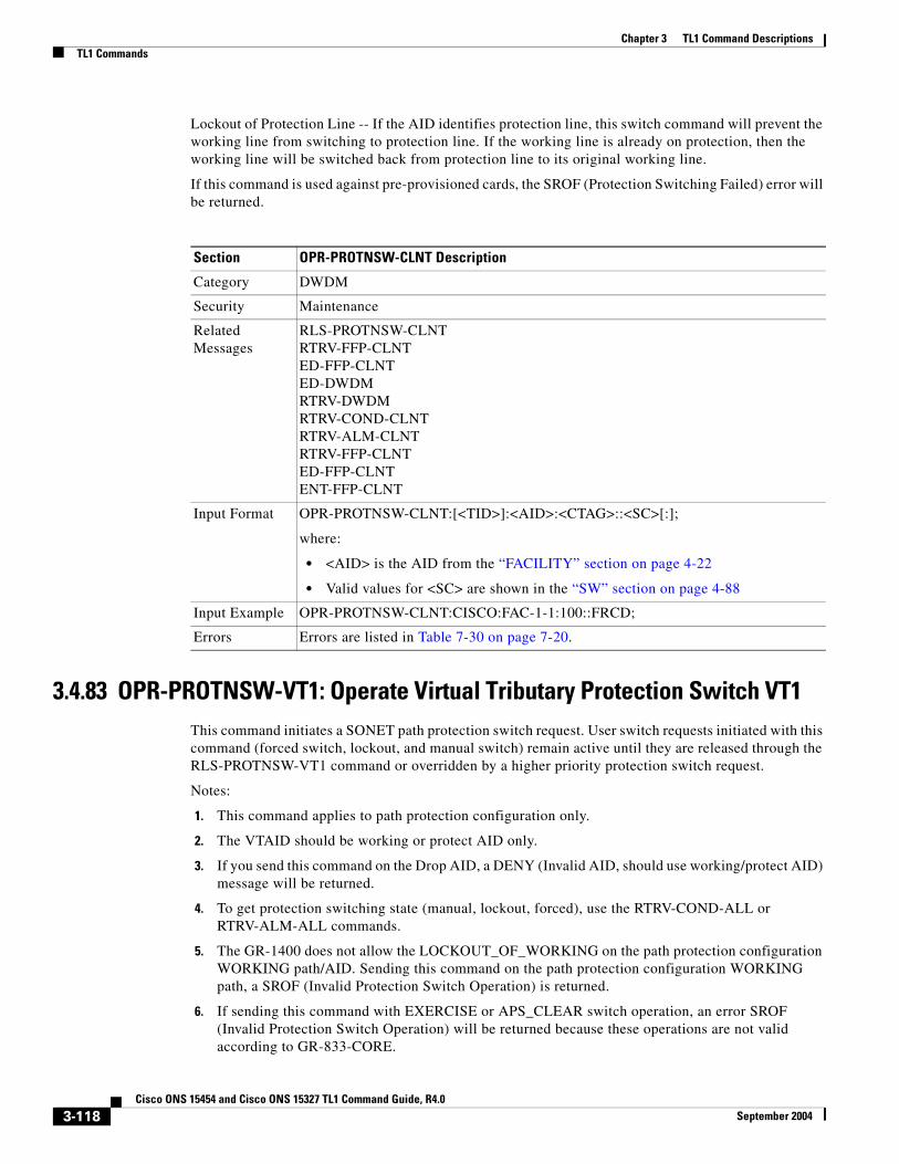
Chapter 3 TL1 Command DescriptionsTL1 Commands
Lockout of Protection Line -- If the AID identifies protection line, this switch command will prevent the working line from switching to protection line. If the working line is already on protection, then the working line will be switched back from protection line to its original working line.
If this command is used against pre-provisioned cards, the SROF (Protection Switching Failed) error will be returned.
3.4.83 OPR-PROTNSW-VT1: Operate Virtual Tributary Protection Switch VT1This command initiates a SONET path protection switch request. User switch requests initiated with this command (forced switch, lockout, and manual switch) remain active until they are released through the RLS-PROTNSW-VT1 command or overridden by a higher priority protection switch request.
Notes:
1. This command applies to path protection configuration only.
2. The VTAID should be working or protect AID only.
3. If you send this command on the Drop AID, a DENY (Invalid AID, should use working/protect AID) message will be returned.
4. To get protection switching state (manual, lockout, forced), use the RTRV-COND-ALL or RTRV-ALM-ALL commands.
5. The GR-1400 does not allow the LOCKOUT_OF_WORKING on the path protection configuration WORKING path/AID. Sending this command on the path protection configuration WORKING path, a SROF (Invalid Protection Switch Operation) is returned.
6. If sending this command with EXERCISE or APS_CLEAR switch operation, an error SROF (Invalid Protection Switch Operation) will be returned because these operations are not valid according to GR-833-CORE.
Section OPR-PROTNSW-CLNT Description
Category DWDM
Security Maintenance
Related Messages
RLS-PROTNSW-CLNTRTRV-FFP-CLNTED-FFP-CLNTED-DWDMRTRV-DWDMRTRV-COND-CLNTRTRV-ALM-CLNTRTRV-FFP-CLNTED-FFP-CLNTENT-FFP-CLNT
Input Format OPR-PROTNSW-CLNT:[<TID>]:<AID>:<CTAG>::<SC>[:];
where:
• <AID> is the AID from the “FACILITY” section on page 4-22
• Valid values for <SC> are shown in the “SW” section on page 4-88
Input Example OPR-PROTNSW-CLNT:CISCO:FAC-1-1:100::FRCD;
Errors Errors are listed in Table 7-30 on page 7-20.
3-118Cisco ONS 15454 and Cisco ONS 15327 TL1 Command Guide, R4.0
September 2004

Chapter 3 TL1 Command DescriptionsTL1 Commands
Sending this command with CLEAR switch operation is not a valid operation per GR-833, the NE will clear the state of the line. This behavior will be corrected in a future release.
3.4.84 OPR-SYNCNSW: Operate Synchronization SwitchThis command initiates a switch to the reference specified by the synchronization reference number if the reference supplied is valid.
For manual types of switches the reference to which you want to switch should be of the same quality as the active reference source, otherwise the command will fail.
If you want to switch to a reference of lower quality, use the forced switch option.
The Operate Synchronization Switches are released by the RLS-SYNCNSW command or are overridden by a synchronization reference failure.
Once the switch is effective, a minor alarm “MANSWTOPRI” (Manual Switch to Primary or Secondary Reference...) will be raised for Manual switches and alarms like “FRCDSWTOPRI” (Forced Switch to Primary or Secondary Reference...) will be raised for Forced switches.
Section OPR-PROTNSW-VT1 Description
Category path protection configuration switching
Security Maintenance
Related Messages
OPR-PROTNSW-<STS_PATH>REPT SWRLS-PROTNSW-<STS_PATH>RLS-PROTNSW-VT1RTRV-PROTNSW-<STS_PATH>RTRV-PROTNSW-VT1
Input Format OPR-PROTNSW-VT1:[<TID>]:<AID>:<CTAG>::<SC>[:];
where:
• <AID> identifies the entity in the NE to which the switch request is directed and is from the “VT1_5” section on page 4-30
• <SC> is the switch command that is to be initiated on the paths; valid values for <SC> are shown in the “SW” section on page 4-88
Input Example OPR-PROTNSW-VT1:CISCO:VT1-5-2-4-1:123::MAN;
Errors Errors are listed in Table 7-30 on page 7-20.
Section OPR-SYNCNSW Description
Category Synchronization
Security Maintenance
3-119Cisco ONS 15454 and Cisco ONS 15327 TL1 Command Guide, R4.0
September 2004

Chapter 3 TL1 Command DescriptionsTL1 Commands
3.4.85 REPT ALM <MOD2ALM>: Report Alarm (CLNT, DS1, E100, E1000, EC1, FSTE, G1000, GIGE, OC12, OC192, OC3, OC48, OCH, POS, STS1, STS12C, STS192C, STS24C, STS3C, STS48C, STS6C, STS9C, T1, T3, UDCDCC, UDCF, VT1)
See Table 4-11 on page 4-6 for supported modifiers by platform.
Reports an alarm condition against a facility or a path.
Related Messages
ED-BITS RTRV-ALM-BITSED-NE-SYNCN RTRV-ALM-SYNCNED-SYNCN RTRV-BITSREPT ALM BITS RTRV-COND-BITSREPT ALM SYNCN RTRV-COND-SYNCNREPT EVT BITS RTRV-NE-SYNCNREPT EVT SYNCN RTRV-SYNCNRLS-SYNCNSW
Input Format OPR-SYNCNSW:[<TID>]:[<AID>]:<CTAG>::<SWITCHTO>,[<SC>];
where:
• <AID> is the access identifier from the “SYNC_REF” section on page 4-28. THe default value is SYNC-NE.
• <SWITCHTO> identifies the new synchronization reference that will be used and is the AID from the “SYNCSW” section on page 4-29
• <SC> is the switch command to be issued. Only manual (MAN) and forced (FRCD) switches are allowed for this command. Valid values for <SC> are shown in the “SW” section on page 4-88. The default value is “MAN”
Input Example OPR-SYNCNSW:CISCO:SYNC-NE:3::PRI,MAN;
Errors Errors are listed in Table 7-30 on page 7-20.
Section OPR-SYNCNSW Description (continued)
Section REPT ALM <MOD2ALM> Description
Category Fault
Security Retrieve
Related Messages
REPT ALM BITS RTRV-ALM-EQPTREPT ALM COM RTRV-ALM-RINGREPT ALM ENV RTRV-ALM-SYNCNREPT ALM EQPT RTRV-ALM-UCPREPT ALM RING RTRV-COND-<MOD2ALM>REPT ALM SYNCN RTRV-COND-ALLREPT ALM UCP RTRV-COND-BITSREPT EVT COM RTRV-COND-ENVRTRV-ALM-<MOD2ALM> RTRV-COND-EQPTRTRV-ALM-ALL RTRV-COND-RINGRTRV-ALM-BITS RTRV-COND-SYNCNRTRV-ALM-ENV RTRV-COND-UCP
3-120Cisco ONS 15454 and Cisco ONS 15327 TL1 Command Guide, R4.0
September 2004

Chapter 3 TL1 Command DescriptionsTL1 Commands
3.4.86 REPT ALM BITS: Report Alarm Building Integrated Timing SupplyReports an alarm condition on a BITS facility.
Output Format SID DATE TIME** ATAG REPT ALM <MOD2ALM> “<AID>:<NTFCNCDE>,<CONDTYPE>,<SRVEFF>,,,,:[<DESC>], [<AIDDET>]”;
where:
• <AID> is the access identifier from the “ALL” section on page 4-10
• <NTFCNCDE> indicates a 2-letter notification code; valid values for <NTFCNCDE> are shown in the “NOTIF_CODE” section on page 4-78
• <CONDTYPE> indicates an alarm condition; valid values for <CONDTYPE> are shown in the “CONDITION” section on page 4-47
• <SRVEFF> is the effect on service caused by the alarm condition; valid values for <SRVEFF> are shown in the “SERV_EFF” section on page 4-86
• <DESC> is the condition description; <DESC> is a string and is optional
• <AIDDET> specifies the AID type; valid values for <AIDDET> are shown in the “EQPT_TYPE” section on page 4-63, <AIDDET> is optional
Output Example
TID-000 1998-06-20 14:30:00** 100.100 REPT ALM CLNT “FAC-2-1:MJ,LOS,SA,,,,:\“LOSS OF SIGNAL\”,OC12”;
Section REPT ALM <MOD2ALM> Description (continued)
Section REPT ALM BITS Description
Category Synchronization
Security Retrieve
Related Messages
ED-BITS RTRV-ALM-BITSED-NE-SYNCN RTRV-ALM-ENVED-SYNCN RTRV-ALM-EQPTOPR-SYNCNSW RTRV-ALM-RINGREPT ALM <MOD2ALM> RTRV-ALM-SYNCNREPT ALM COM RTRV-ALM-UCPREPT ALM ENV RTRV-BITSREPT ALM EQPT RTRV-COND-<MOD2ALM>REPT ALM RING RTRV-COND-ALLREPT ALM SYNCN RTRV-COND-BITSREPT ALM UCP RTRV-COND-ENVREPT EVT BITS RTRV-COND-EQPTREPT EVT COM RTRV-COND-RINGREPT EVT SYNCN RTRV-COND-SYNCNRLS-SYNCNSW RTRV-COND-UCPRTRV-ALM-<MOD2ALM> RTRV-NE-SYNCNRTRV-ALM-ALL RTRV-SYNCN
3-121Cisco ONS 15454 and Cisco ONS 15327 TL1 Command Guide, R4.0
September 2004
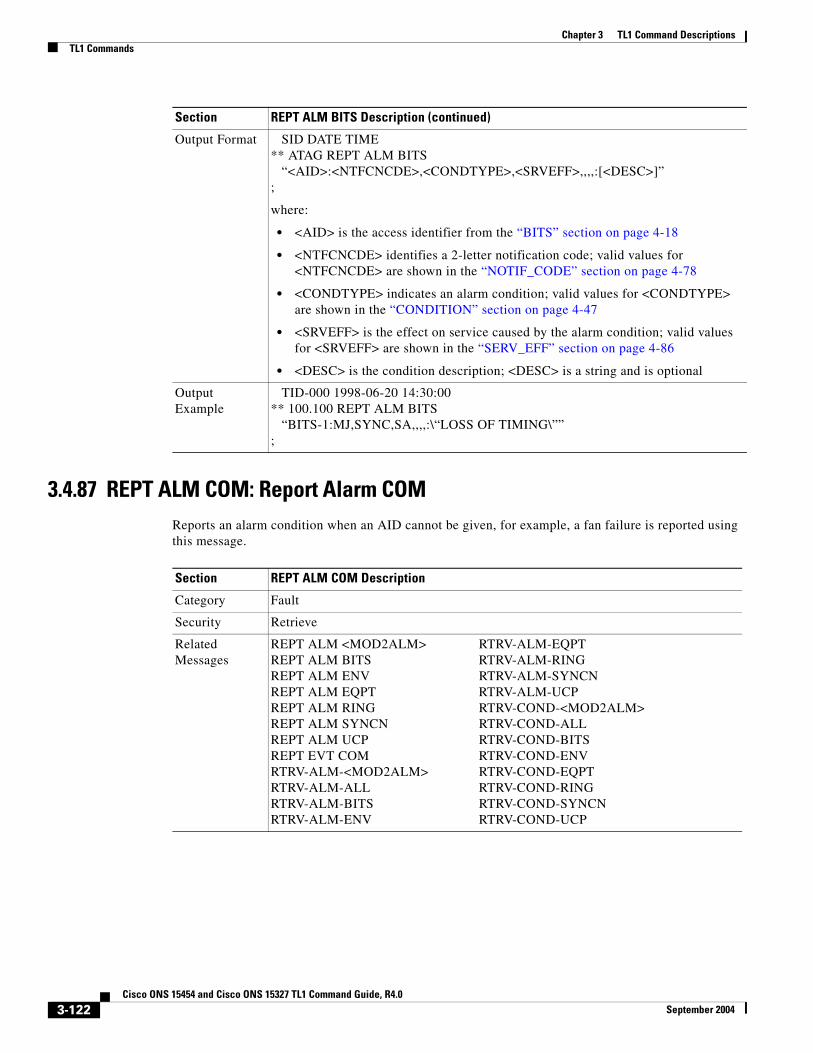
Chapter 3 TL1 Command DescriptionsTL1 Commands
3.4.87 REPT ALM COM: Report Alarm COMReports an alarm condition when an AID cannot be given, for example, a fan failure is reported using this message.
Output Format SID DATE TIME** ATAG REPT ALM BITS “<AID>:<NTFCNCDE>,<CONDTYPE>,<SRVEFF>,,,,:[<DESC>]”;
where:
• <AID> is the access identifier from the “BITS” section on page 4-18
• <NTFCNCDE> identifies a 2-letter notification code; valid values for <NTFCNCDE> are shown in the “NOTIF_CODE” section on page 4-78
• <CONDTYPE> indicates an alarm condition; valid values for <CONDTYPE> are shown in the “CONDITION” section on page 4-47
• <SRVEFF> is the effect on service caused by the alarm condition; valid values for <SRVEFF> are shown in the “SERV_EFF” section on page 4-86
• <DESC> is the condition description; <DESC> is a string and is optional
Output Example
TID-000 1998-06-20 14:30:00** 100.100 REPT ALM BITS “BITS-1:MJ,SYNC,SA,,,,:\“LOSS OF TIMING\””;
Section REPT ALM BITS Description (continued)
Section REPT ALM COM Description
Category Fault
Security Retrieve
Related Messages
REPT ALM <MOD2ALM> RTRV-ALM-EQPTREPT ALM BITS RTRV-ALM-RINGREPT ALM ENV RTRV-ALM-SYNCNREPT ALM EQPT RTRV-ALM-UCPREPT ALM RING RTRV-COND-<MOD2ALM>REPT ALM SYNCN RTRV-COND-ALLREPT ALM UCP RTRV-COND-BITSREPT EVT COM RTRV-COND-ENVRTRV-ALM-<MOD2ALM> RTRV-COND-EQPTRTRV-ALM-ALL RTRV-COND-RINGRTRV-ALM-BITS RTRV-COND-SYNCNRTRV-ALM-ENV RTRV-COND-UCP
3-122Cisco ONS 15454 and Cisco ONS 15327 TL1 Command Guide, R4.0
September 2004

Chapter 3 TL1 Command DescriptionsTL1 Commands
3.4.88 REPT ALM ENV: Report Alarm EnvironmentReports a customer-defined condition on an environmental alarm input.
Output Format SID DATE TIME** ATAG REPT ALM COM “[<AID>]:<NTFCNCDE>,<CONDTYPE>,<SRVEFF>,,,,:[<DESC>]” ;
where:
• <AID> indicates the alarm without AID; <AID> is a string and is optional
• <NTFCNCDE> indicates a notification code; valid values for <NTFCNCDE> are shown in the “NOTIF_CODE” section on page 4-78
• <CONDTYPE> indicates an alarm condition; valid values for <CONDTYPE> are shown in the “CONDITION” section on page 4-47
• <SRVEFF> is the effect on service caused by the alarm condition; valid values for <SRVEFF> are shown in the “SERV_EFF” section on page 4-86
• <DESC> is the condition description; <DESC> is a string and is optional
Output Example
TID-000 1998-06-20 14:30:00** 100.100 REPT ALM COM “COM:MJ,FAN,NSA,,,,:\“FAN FAILURE\””;
Section REPT ALM COM Description (continued)
Section REPT ALM ENV Description
Category Environment Alarms and Controls
Security Retrieve
Related Messages
OPR-ACO-ALL RTRV-ALM-RINGOPR-EXT-CONT RTRV-ALM-SYNCNREPT ALM <MOD2ALM> RTRV-ALM-UCPREPT ALM BITS RTRV-ATTR-CONTREPT ALM COM RTRV-ATTR-ENVREPT ALM EQPT RTRV-COND-<MOD2ALM>REPT ALM RING RTRV-COND-ALLREPT ALM SYNCN RTRV-COND-BITSREPT ALM UCP RTRV-COND-ENVREPT EVT COM RTRV-COND-EQPTREPT EVT ENV RTRV-COND-RINGRLS-EXT-CONT RTRV-COND-SYNCNRTRV-ALM-<MOD2ALM> RTRV-COND-UCPRTRV-ALM-ALL RTRV-EXT-CONTRTRV-ALM-BITS SET-ATTR-CONTRTRV-ALM-ENV SET-ATTR-ENVRTRV-ALM-EQPT
3-123Cisco ONS 15454 and Cisco ONS 15327 TL1 Command Guide, R4.0
September 2004

Chapter 3 TL1 Command DescriptionsTL1 Commands
3.4.89 REPT ALM EQPT: Report Alarm Equipment Reports an alarm condition against an equipment unit or slot.
Output Format SID DATE TIME** ATAG REPT ALM ENV “<AID>:<NTFCNCDE>,<ALMTYPE>,,,[<DESC>]”;
where:
• <AID> identifies an environmental input and is from the “ENV” section on page 4-20
• <NTFCNCDE> identifies a 2-letter notification code; valid values for <NTFCNCDE> are shown in the “NOTIF_CODE” section on page 4-78
• <ALMTYPE> abbreviated code identifying the alarm; valid values for <ALMTYPE> are shown in the “ENV_ALM” section on page 4-62
• <DESC> is the alarm message; <DESC> is a string and is optional
Output Example
TID-000 1998-06-20 14:30:00** 100.100 REPT ALM ENV “ENV-IN-1:MJ,OPENDR,,,\“OPEN DOOR\””;
Section REPT ALM ENV Description (continued)
Section REPT ALM EQPT Description
Category Equipment
Security Retrieve
Related Messages
ALW-SWDX-EQPT RTRV-ALM-ALLALW-SWTOPROTN-EQPT RTRV-ALM-BITSALW-SWTOWKG-EQPT RTRV-ALM-ENVDLT-EQPT RTRV-ALM-EQPTED-EQPT RTRV-ALM-RINGENT-EQPT RTRV-ALM-SYNCNINH-SWDX-EQPT RTRV-ALM-UCPINH-SWTOPROTN-EQPT RTRV-COND-<MOD2ALM>INH-SWTOWKG-EQPT RTRV-COND-ALLREPT ALM <MOD2ALM> RTRV-COND-BITSREPT ALM BITS RTRV-COND-ENVREPT ALM COM RTRV-COND-EQPTREPT ALM ENV RTRV-COND-RINGREPT ALM RING RTRV-COND-SYNCNREPT ALM SYNCN RTRV-COND-UCPREPT ALM UCP RTRV-EQPTREPT EVT COM SW-DX-EQPTREPT EVT EQPT SW-TOPROTN-EQPTRTRV-ALM-<MOD2ALM> SW-TOWKG-EQPT
3-124Cisco ONS 15454 and Cisco ONS 15327 TL1 Command Guide, R4.0
September 2004

Chapter 3 TL1 Command DescriptionsTL1 Commands
3.4.90 REPT ALM RING: Report Alarm RingReports an alarm condition against a ring object for BLSR.
Output Format SID DATE TIME** ATAG REPT ALM EQPT “<AID>:<NTFCNCDE>,<CONDITION>,<SRVEFF>,,,,:[<DESC>], [<AIDDET>]”;
where:
• <AID> is the equipment AID SLOT from the “EQPT” section on page 4-21
• <NTFCNCDE> is the notification code; valid values for <NTFCNCDE> are shown in the “NOTIF_CODE” section on page 4-78
• <CONDITION> is the type of alarm condition; valid values for <CONDTYPE> are shown in the “CONDITION” section on page 4-47
• <SRVEFF> is the effect on service caused by the alarm condition; valid values for <SRVEFF> are shown in the “SERV_EFF” section on page 4-86
• <DESC> is the condition description; <DESC> is a string and is optional
• <AIDDET> specifies the type of AID; valid values for <AIDDET> are shown in the “EQPT_TYPE” section on page 4-63, <AIDDET> is optional
Output Example
TID-000 1998-06-20 14:30:00** 100.100 REPT ALM EQPT “SLOT-7:MJ,CONTR,NSA,,,,:\“CONTROLLER FAILURE\”,TCC”;
Section REPT ALM EQPT Description (continued)
Section REPT ALM RING Description
Category Fault
Security Retrieve
Related Messages
DLT-BLSR RTRV-ALM-ENVED-BLSR RTRV-ALM-EQPTREPT ALM <MOD2ALM> RTRV-ALM-RINGREPT ALM BITS RTRV-ALM-SYNCNREPT ALM COM RTRV-ALM-UCPREPT ALM ENV RTRV-BLSRREPT ALM EQPT RTRV-COND-<MOD2ALM>REPT ALM SYNCN RTRV-COND-ALLREPT ALM UCP RTRV-COND-BITSREPT EVT COM RTRV-COND-ENVREPT EVT RING RTRV-COND-EQPTRTRV-ALM-<MOD2ALM> RTRV-COND-RINGRTRV-ALM-ALL RTRV-COND-SYNCNRTRV-ALM-BITS RTRV-COND-UCP
3-125Cisco ONS 15454 and Cisco ONS 15327 TL1 Command Guide, R4.0
September 2004

Chapter 3 TL1 Command DescriptionsTL1 Commands
3.4.91 REPT ALM SYNCN: Report Alarm SynchronizationReports an alarm condition against a synchronization reference.
Output Format SID DATE TIME** ATAG REPT ALM RING “<AID>:<NTFCNCDE>,<CONDTYPE>,<SRVEFF>,,,,:[<DESC>]”;
where:
• <AID> is from the “BLSR” section on page 4-18
• <NTFCNCDE> indicates a 2-letter notification code; valid values for <NTFCNCDE> are shown in the “NOTIF_CODE” section on page 4-78
• <CONDTYPE> indicates a BLSR alarm; valid values for <CONDTYPE> are shown in the “CONDITION” section on page 4-47
• <SRVEFF> is the effect on service caused by the alarm condition; valid values for <SRVEFF> are shown in the “SERV_EFF” section on page 4-86
• <DESC> is the condition description; <DESC> is a string and is optional
Output Example
TID-000 1998-06-20 14:30:00** 100.100 REPT ALM RING “BLSR-999:MJ,PRC-DUPID,SA,,,,:\“DUPLICATE NODE ID\”,”;
Section REPT ALM RING Description (continued)
Section REPT ALM SYNCN Description
Category Synchronization
Security Retrieve
Related Messages
ED-BITS RTRV-ALM-BITSED-NE-SYNCN RTRV-ALM-ENVED-SYNCN RTRV-ALM-EQPTOPR-SYNCNSW RTRV-ALM-RINGREPT ALM <MOD2ALM> RTRV-ALM-SYNCNREPT ALM BITS RTRV-ALM-UCPREPT ALM COM RTRV-BITSREPT ALM ENV RTRV-COND-<MOD2ALM>REPT ALM EQPT RTRV-COND-ALLREPT ALM RING RTRV-COND-BITSREPT ALM UCP RTRV-COND-ENVREPT EVT BITS RTRV-COND-EQPTREPT EVT COM RTRV-COND-RINGREPT EVT SYNCN RTRV-COND-SYNCNRLS-SYNCNSW RTRV-COND-UCPRTRV-ALM-<MOD2ALM> RTRV-NE-SYNCRTRV-ALM-ALL RTRV-SYNCN
3-126Cisco ONS 15454 and Cisco ONS 15327 TL1 Command Guide, R4.0
September 2004

Chapter 3 TL1 Command DescriptionsTL1 Commands
3.4.92 REPT ALM UCP: Report Alarm Unified Control PlaneReports an alarm condition against a UCP object.
Output Format SID DATE TIME** ATAG REPT ALM SYNCN “<AID>:<NTFCNCDE>,<CONDTYPE>,<SRVEFF>,,,,:[<DESC>]”;
where:
• <AID> identifies a synchronization reference with alarm condition and is from the “SYNC_REF” section on page 4-28
• <NTFCNCDE> indicates a 2-letter notification code; valid values for <NTFCNCDE> are shown in the “NOTIF_CODE” section on page 4-78
• <CONDTYPE> indicates an alarm condition; valid values for <CONDTYPE> are shown in the “CONDITION” section on page 4-47
• <SRVEFF> is the effect on service caused by the alarm condition; valid values for <SRVEFF> are shown in the “SERV_EFF” section on page 4-86
• <DESC> is the condition description; <DESC> is a string and is optional
Output Example
TID-000 1998-06-20 14:30:00** 100.100 REPT ALM SYNCN “SYNC-NE:MJ,MAN,SA,,,,:\“MANUAL SWITCH\”,”;
Section REPT ALM SYNCN Description (continued)
Section REPT ALM UCP Description
Category UCP
Security Retrieve
Related Messages
DLT-UCP-CC REPT ALM RINGDLT-UCP-IF REPT ALM SYNCNDLT-UCP-NBR REPT ALM UCPED-UCP-CC RTRV-COND-<MOD2ALM>ED-UCP-IF RTRV-COND-ALLED-UCP-NBR RTRV-COND-BITSED-UCP-NODE RTRV-COND-ENVENT-UCP-CC RTRV-COND-EQPTENT-UCP-IF RTRV-COND-RINGENT-UCP-NBR RTRV-COND-SYNCNREPT ALM <MOD2ALM> RTRV-COND-UCPREPT ALM BITS RTRV-UCP-CCREPT ALM COM RTRV-UCP-IFREPT ALM UCP RTRV-UCP-NBRREPT ALM ENV RTRV-UCP-NODEREPT ALM EQPT
3-127Cisco ONS 15454 and Cisco ONS 15327 TL1 Command Guide, R4.0
September 2004

Chapter 3 TL1 Command DescriptionsTL1 Commands
3.4.93 REPT DBCHG: Report Database Change MessageReports any changes on the NE that result from:
1. TL1 provisioning commands or their GUI equivalents containing the verbs: ALW, DLT, ED, ENT, INH, INIT, OPR, RLS, SET, and SW (for example, DLT-EQPT, ENT-CRS-STS1)
2. External event such as a board insertion.
Output Format SID DATE TIME** ATAG REPT ALM UCP “<AID>:<NTFCNCDE>,<CONDTYPE>,<SRVEFF>,,,,:[<DESC>]”;
where:
• <AID> identifies a UCP object with alarm condition and is from the “ALL” section on page 4-10
• <NTFCNCDE> is a notification code; valid values for <NTFCNCDE> are shown in the “NOTIF_CODE” section on page 4-78
• <CONDTYPE> is the type of condition to be retrieved; valid values for <CONDTYPE> are shown in the “CONDITION” section on page 4-47
• <SRVEFF> is the effect on service caused by the alarm condition; valid values for <SRVEFF> are shown in the “SERV_EFF” section on page 4-86
• <DESC> is the condition description; <DESC> is a string and is optional
Output Example
TID-000 1998-06-20 14:30:00** 100.100 REPT ALM UCP “CC-1:MJ,LMP-HELLODOWN,SA,,,,: \“LMP HELLO FSM ON CONTROL CHANNEL DOWN\”,”;
Section REPT ALM UCP Description (continued)
Section REPT DBCHG Description
Category Log
Security Retrieve
Related Messages
ALW-MSG-DBCHGINH-MSG-DBCHGRTRV-LOG
3-128Cisco ONS 15454 and Cisco ONS 15327 TL1 Command Guide, R4.0
September 2004

Chapter 3 TL1 Command DescriptionsTL1 Commands
Output Format SID DATE TIMEA ATAG REPT DBCHG “TIME=<TIME>,DATE=<DATE>,[SOURCE=<SOURCE>,] [USERID=<USERID>,]DBCHGSEQ=<DBCHGSEQ>:<COMMAND>:<VT>”;
where:
• <TIME> is the time of the message triggered by the NE; <TIME> is a time
• <DATE> is the date of the message triggered by the NE; <DATE> is a date
• <SOURCE> is an input command CTAG if present; <SOURCE> is an integer and is optional
• <USERID> is the user name or user identifier; <USERID> is a string and is optional
• <DBCHGSEQ> is a sequential number of the DBCHG message; <DBCHGSEQ> is an integer
• <COMMAND> is the input command or substitute; <COMMAND> is a string
• <VT> is the AID from the “VT1_5” section on page 4-30
Output Example
TID-000 1998-06-20 14:30:00A 001 REPT DBCHG “TIME=14-35-46,DATE=99-07-28,SOURCE=123,USERID=CISCO15, DBCHGSEQ=456:ENT-CRS-VT1:VT1-4-1-2-6-4”;
Section REPT DBCHG Description (continued)
3-129Cisco ONS 15454 and Cisco ONS 15327 TL1 Command Guide, R4.0
September 2004

Chapter 3 TL1 Command DescriptionsTL1 Commands
3.4.94 REPT EVT <MOD2ALM>: Report Event (CLNT, DS1, E100, E1000, EC1, FSTE, G1000, GIGE, OC12, OC192, OC3, OC48, OCH, POS, STS1, STS12C, STS192C, STS24C, STS3C, STS48C, STS6C, STS9C, T1, T3, UDCDCC, UDCF, VT1)
See Table 4-11 on page 4-6 for supported modifiers by platform.
Reports the occurrence of a non-alarmed event.
Section REPT EVT <MOD2ALM> Description
Category Fault
Security Retrieve
Related Messages
—
Output Format SID DATE TIMEA ATAG REPT EVT <MOD2ALM> “<AID>:<CONDTYPE>,[<CONDEFF>],,,[<LOCN>],,[<MONVAL>], [<THLEV>],[<TMPER>]:[<DESC>],[<AIDDET>]”;
where:
• <AID> indicates an event with the condition type and is from the “ALL” section on page 4-10
• <CONDTYPE> indicates an event with the condition type and is a string
• <CONDEFF> is the effect of the condition on the NE; valid values are shown in the “COND_EFF” section on page 4-47, <CONDEFF> is optional
• <LOCN> indicates the location; valid values for <LOCN> are shown in the “LOCATION” section on page 4-71, <LOCN> is optional
• <MONVAL> is the monitored value and is a float; <MONVAL> is an integer and is optional
• <THLEV> is the threshold value and is a float; <THLEV> is an integer and is optional
• <TMPER> is the accumulation time period for the PM information; valid values for <TMPER> are shown in the “TMPER” section on page 4-93. <TMPER> is optional
• <DESC> is the condition description; <DESC> is a string and is optional
• <AIDDET> specifies the type of AID; valid values for <AIDDET> are shown in the “EQPT_TYPE” section on page 4-63, <AIDDET> is optional
Output Example
TID-000 1998-06-20 14:30:00A 100.100 REPT EVT DS1 “FAC-5-1:WKSWPR,TC,,,FEND,,12,13,15-MIN: \“WORKING SWITCH TO PROTECTION\”,OC48”;
3-130Cisco ONS 15454 and Cisco ONS 15327 TL1 Command Guide, R4.0
September 2004

Chapter 3 TL1 Command DescriptionsTL1 Commands
3.4.95 REPT EVT BITS: Report Event BITSReports a non-alarmed event against a BITS facility.
Section REPT EVT BITS Description
Category Synchronization
Security Retrieve
Related Messages
ED-BITS RTRV-ALM-BITSED-NE-SYNCN RTRV-ALM-SYNCNED-SYNCN RTRV-BITSOPR-SYNCNSW RTRV-COND-BITSREPT ALM BITS RTRV-COND-SYNCNREPT ALM SYNCN RTRV-NE-SYNCNREPT EVT SYNCN RTRV-SYNCNRLS-SYNCNSW
Output Format SID DATE TIMEA ATAG REPT EVT BITS “<AID>:<CONDTYPE>,[<CONDEFF>],,,,,,,:[<DESC>]”;
where:
• <AID> indicates an access identifier and is from the “BITS” section on page 4-18
• <CONDTYPE> indicates a condition type and the valid values are shown in the “CONDITION” section on page 4-47
• <CONDEFF> indicates an effect of the condition on the NE; valid values for are shown in the “COND_EFF” section on page 4-47, <CONDEFF> is optional
• <DESC> is the condition description; <DESC> is a string and is optional
OutputExample
TID-000 1998-06-20 14:30:00A 100.100 REPT EVT BITS “BITS-1:SSM-STU,TC,,,,,,,:\“SYNCHRONIZED - TRACEABILITY UNKNOWN\””;
3-131Cisco ONS 15454 and Cisco ONS 15327 TL1 Command Guide, R4.0
September 2004

Chapter 3 TL1 Command DescriptionsTL1 Commands
3.4.96 REPT EVT COM: Report Event COMReports a non-alarmed event against an NE when there is no AID associated with it.
Section REPT EVT COM Description
Category Fault
Security Retrieve
Related Messages
REPT ALM <MOD2ALM> RTRV-ALM-EQPTREPT ALM BITS RTRV-ALM-RINGREPT ALM COM RTRV-ALM-SYNCNREPT ALM ENV RTRV-ALM-UCPREPT ALM EQPT RTRV-COND-<MOD2ALM>REPT ALM RING RTRV-COND-ALLREPT ALM SYNCN RTRV-COND-BITSREPT ALM UCP RTRV-COND-ENVRTRV-ALM-<MOD2ALM> RTRV-COND-EQPTRTRV-ALM-ALL RTRV-COND-RINGRTRV-ALM-BITS RTRV-COND-SYNCNRTRV-ALM-ENV RTRV-COND-UCP
Output Format SID DATE TIMEA ATAG REPT EVT COM “[<AID>]:<CONDTYPE>,[<CONDEFF>],,,,,,,:[<DESC>]”;
where:
• <AID> indicates this event is from the NE. <AID> is a string and is optional.
• <CONDTYPE> indicates an event condition type. Valid values are shown in the “CONDITION” section on page 4-47
• <CONDEFF> indicates an effect of the condition on the NE; valid values for <CONDEFF> are shown in the “COND_EFF” section on page 4-47, <CONDEFF> is optional
• <DESC> is the description message for the condition; <DESC> is a string and is optional
OutputExample
TID-000 1998-06-20 14:30:00A 100.100 REPT EVT COM “COM:CLDRESTART,TC,,,,,,,:\“COLD RESTART\”,”;
3-132Cisco ONS 15454 and Cisco ONS 15327 TL1 Command Guide, R4.0
September 2004

Chapter 3 TL1 Command DescriptionsTL1 Commands
3.4.97 REPT EVT ENV: Report Event EnvironmentReports the occurrence of a non-alarmed event against an environment alarm input.
Section REPT EVT ENV Description
Category Environment Alarms and Controls
Security Retrieve
Related Messages
OPR-ACO-ALL RTRV-ATTR-ENVOPR-EXT-CONT RTRV-COND-ENVREPT ALM ENV RTRV-EXT-CONTRLS-EXT-CONT SET-ATTR-CONTRTRV-ALM-ENV SET-ATTR-ENVRTRV-ATTR-CONT
Output Format SID DATE TIMEA ATAG REPT EVT ENV “<AID>:<ALMTYPE>,[<CONDEFF>],,,,,,,:[<DESC>]”;
where:
• <AID> identifies an environmental input and is from the “ENV” section on page 4-20
• <ALMTYPE> is an abbreviated code identifying the alarm and the valid values are shown in the “ENV_ALM” section on page 4-62
• <CONDEFF> indicates an effect of the condition on the NE; valid values for <CONDEFF> are shown in the “COND_EFF” section on page 4-47, <CONDEFF> is optional
• <DESC> is an alarm message; <DESC> is a string and is optional
OutputExample
TID-000 1998-06-20 14:30:00A 100.100 REPT EVT ENV “ENV-IN-2:OPENDR,TC,,,,,,,:\“OPEN DOOR\””;
3-133Cisco ONS 15454 and Cisco ONS 15327 TL1 Command Guide, R4.0
September 2004
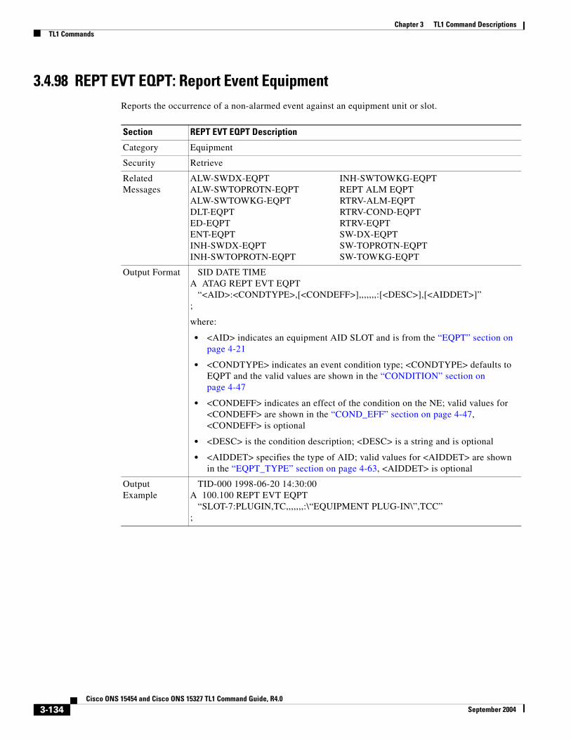
Chapter 3 TL1 Command DescriptionsTL1 Commands
3.4.98 REPT EVT EQPT: Report Event Equipment Reports the occurrence of a non-alarmed event against an equipment unit or slot.
Section REPT EVT EQPT Description
Category Equipment
Security Retrieve
Related Messages
ALW-SWDX-EQPT INH-SWTOWKG-EQPTALW-SWTOPROTN-EQPT REPT ALM EQPTALW-SWTOWKG-EQPT RTRV-ALM-EQPTDLT-EQPT RTRV-COND-EQPTED-EQPT RTRV-EQPTENT-EQPT SW-DX-EQPTINH-SWDX-EQPT SW-TOPROTN-EQPTINH-SWTOPROTN-EQPT SW-TOWKG-EQPT
Output Format SID DATE TIMEA ATAG REPT EVT EQPT “<AID>:<CONDTYPE>,[<CONDEFF>],,,,,,,:[<DESC>],[<AIDDET>]”;
where:
• <AID> indicates an equipment AID SLOT and is from the “EQPT” section on page 4-21
• <CONDTYPE> indicates an event condition type; <CONDTYPE> defaults to EQPT and the valid values are shown in the “CONDITION” section on page 4-47
• <CONDEFF> indicates an effect of the condition on the NE; valid values for <CONDEFF> are shown in the “COND_EFF” section on page 4-47, <CONDEFF> is optional
• <DESC> is the condition description; <DESC> is a string and is optional
• <AIDDET> specifies the type of AID; valid values for <AIDDET> are shown in the “EQPT_TYPE” section on page 4-63, <AIDDET> is optional
Output Example
TID-000 1998-06-20 14:30:00A 100.100 REPT EVT EQPT “SLOT-7:PLUGIN,TC,,,,,,,:\“EQUIPMENT PLUG-IN\”,TCC”;
3-134Cisco ONS 15454 and Cisco ONS 15327 TL1 Command Guide, R4.0
September 2004
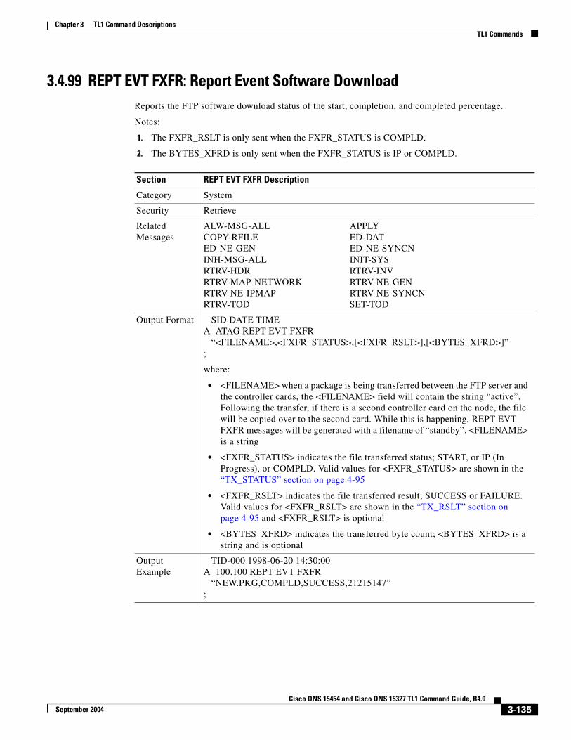
Chapter 3 TL1 Command DescriptionsTL1 Commands
3.4.99 REPT EVT FXFR: Report Event Software DownloadReports the FTP software download status of the start, completion, and completed percentage.
Notes:
1. The FXFR_RSLT is only sent when the FXFR_STATUS is COMPLD.
2. The BYTES_XFRD is only sent when the FXFR_STATUS is IP or COMPLD.
Section REPT EVT FXFR Description
Category System
Security Retrieve
Related Messages
ALW-MSG-ALL APPLYCOPY-RFILE ED-DATED-NE-GEN ED-NE-SYNCNINH-MSG-ALL INIT-SYSRTRV-HDR RTRV-INVRTRV-MAP-NETWORK RTRV-NE-GENRTRV-NE-IPMAP RTRV-NE-SYNCNRTRV-TOD SET-TOD
Output Format SID DATE TIMEA ATAG REPT EVT FXFR “<FILENAME>,<FXFR_STATUS>,[<FXFR_RSLT>],[<BYTES_XFRD>]”;
where:
• <FILENAME> when a package is being transferred between the FTP server and the controller cards, the <FILENAME> field will contain the string “active”. Following the transfer, if there is a second controller card on the node, the file will be copied over to the second card. While this is happening, REPT EVT FXFR messages will be generated with a filename of “standby”. <FILENAME> is a string
• <FXFR_STATUS> indicates the file transferred status; START, or IP (In Progress), or COMPLD. Valid values for <FXFR_STATUS> are shown in the “TX_STATUS” section on page 4-95
• <FXFR_RSLT> indicates the file transferred result; SUCCESS or FAILURE. Valid values for <FXFR_RSLT> are shown in the “TX_RSLT” section on page 4-95 and <FXFR_RSLT> is optional
• <BYTES_XFRD> indicates the transferred byte count; <BYTES_XFRD> is a string and is optional
Output Example
TID-000 1998-06-20 14:30:00A 100.100 REPT EVT FXFR “NEW.PKG,COMPLD,SUCCESS,21215147”;
3-135Cisco ONS 15454 and Cisco ONS 15327 TL1 Command Guide, R4.0
September 2004

Chapter 3 TL1 Command DescriptionsTL1 Commands
3.4.100 REPT EVT IOSCFG: Report Event IOS Config File(Cisco ONS 15454 only)
Reports the status of copying the IOS configuration file when the COPY-IOSCFG command is issued.
Notes:
1. You can identify if this message is caused by an IOS config file downloading/uploading/merging by looking at the SRC and DEST field in the message. Refer to the COPY-IOSCFG command for more details.
2. There is no success/failure in the message to indicate the success or failure of the merge process when merging the startup IOS config file to the running config file.
Section REPT EVT IOSCFG Description
Category IOS
Security Retrieve
Related Messages
COPY IOSCFG
Output Format SID DATE TIMEA ATAG REPT EVT IOSCFG “<AID>:<SRC>,<DEST>,<STATUS>,[<RESULT>]”;
where:
• <AID> slot AID for the equipment and is from the AID “EQPT” section on page 4-21
• <SRC> specifies where the IOS config file is copied from and is a string
• <DEST> specifies where the IOS config file is copied to and is a string
• <STATUS> indicates the status of COPY-IOSCFG: Start, IP (In Process), or COMPLD; valid values are shown in the “TX_STATUS” section on page 4-95
• <RESULT> indicates the result of COPY-IOSCFG: Success or Failure; valid values are shown in the “TX_RSLT” section on page 4-95 and <RESULT> is optional
Output Example
TID-000 1998-06-20 14:30:00A 100.100 REPT EVT IOSCFG “SLOT-1:STARTUP,IOS-CONFIG-FILE-IN-NETWORK,COMPLD,SUCCESS”;
Errors Errors are listed in Table 7-30 on page 7-20.
3-136Cisco ONS 15454 and Cisco ONS 15327 TL1 Command Guide, R4.0
September 2004
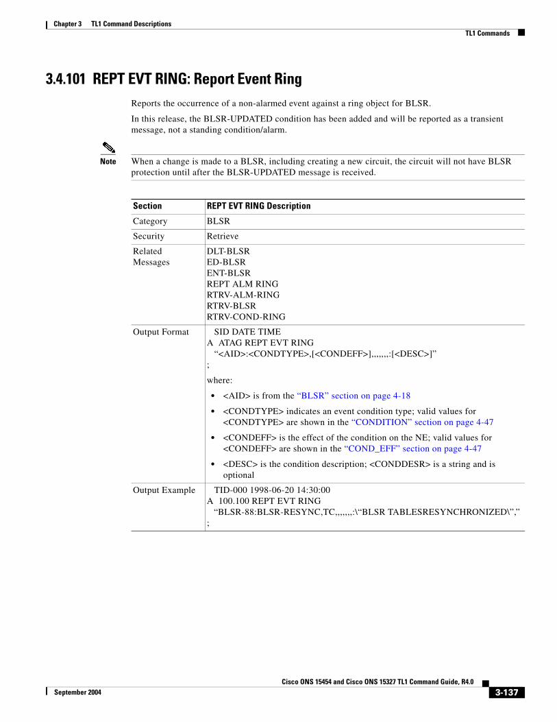
Chapter 3 TL1 Command DescriptionsTL1 Commands
3.4.101 REPT EVT RING: Report Event RingReports the occurrence of a non-alarmed event against a ring object for BLSR.
In this release, the BLSR-UPDATED condition has been added and will be reported as a transient message, not a standing condition/alarm.
Note When a change is made to a BLSR, including creating a new circuit, the circuit will not have BLSR protection until after the BLSR-UPDATED message is received.
Section REPT EVT RING Description
Category BLSR
Security Retrieve
Related Messages
DLT-BLSRED-BLSRENT-BLSRREPT ALM RINGRTRV-ALM-RINGRTRV-BLSRRTRV-COND-RING
Output Format SID DATE TIMEA ATAG REPT EVT RING “<AID>:<CONDTYPE>,[<CONDEFF>],,,,,,,:[<DESC>]”;
where:
• <AID> is from the “BLSR” section on page 4-18
• <CONDTYPE> indicates an event condition type; valid values for <CONDTYPE> are shown in the “CONDITION” section on page 4-47
• <CONDEFF> is the effect of the condition on the NE; valid values for <CONDEFF> are shown in the “COND_EFF” section on page 4-47
• <DESC> is the condition description; <CONDDESR> is a string and is optional
Output Example TID-000 1998-06-20 14:30:00A 100.100 REPT EVT RING “BLSR-88:BLSR-RESYNC,TC,,,,,,,:\“BLSR TABLESRESYNCHRONIZED\”,”;
3-137Cisco ONS 15454 and Cisco ONS 15327 TL1 Command Guide, R4.0
September 2004

Chapter 3 TL1 Command DescriptionsTL1 Commands
3.4.102 REPT EVT SECU: Report Event SecurityReports the occurrence of a non-alarmed security event against the NE.
Based on TR-NWT-000835 in TR-NWT-000835 and the AID of the security alarm should be the Connection Identifier (CID) which is not supported in this release. The COM or UID is an acceptable substitute for the AID here. CID’s will be supported in a future release.
For the rule of single failure, single message/alarm, the security alarm will not be reported as REPT ALM COM, because it is reported as REPT ALM SECU.
Because the NE sends this security message as a transient message, to make all TL1 autonomous messages consistent, the TL1 agent reports the security message into REPT EVT SECU.
Section REPT EVT SECU Description
Category Security
Security Retrieve
Related Messages ACT-USERCANCCANC-USERDLT-USER-SECUED-PIDED-USER-SECUENT-USER-SECURTRV-USER-SECU
Output Format SID DATE TIMEA ATAG REPT EVT SECU “<AID>:<CONDTYPE>,[<CONDEFF>],,,,,,,:[<DESC>]”;
where:
• <AID> identifies an entity with the condition and defaults to “COM”; <AID> is a string
• <CONDTYPE> is the condition type and valid values are shown in the “CONDITION” section on page 4-47
• <CONDEFF> indicates an effect of the condition on the NE and valid values are shown in the “COND_EFF” section on page 4-47; <CONDEFF> is optional
• <DESC> is the condition description; <DESC> is a string and is optional
Output Example TID-000 1998-06-20 14:30:00A 100.100 REPT EVT SECU “COM:INTRUSION,TC,,,,,,,:\“SECURITY-INVALID LOGIN (SEE AUDIT TRIAL)\””;
3-138Cisco ONS 15454 and Cisco ONS 15327 TL1 Command Guide, R4.0
September 2004

Chapter 3 TL1 Command DescriptionsTL1 Commands
3.4.103 REPT EVT SESSION: Report Event SessionReports a non-alarmed event related to establishing a session with the NE.
Notes:
1. The WARN field may contain different information depending on the type of session-related event.
2. If a session is terminated for any reason (except a user timeout), this message is sent to indicate the reason for the session termination.
Section REPT EVT SESSION Description
Category Security
Security Retrieve
Related Messages ACT-USER ED-USER-SECUALW-MSG-SECU ENT-USER-SECUCANC INH-MSG-SECUCANC-USER REPT EVT SECUDLT-USER-SECU RTRV-USER-SECUED-PID
Output Format SID DATE TIMEA ATAG REPT EVT SESSION “<AID>:<EXP>,[<PCN>]”;
where:
• <AID> identifies the NE with which a session is being attempted; <AID> is a string
• <EXP> indicates whether the password is “alive” (i.e., no password updating is required at the moment), has expired, or is about to expire. For release 4.0, this value is always NO. Valid values are shown in the “EXP” section on page 4-68
• <PCN> not applicable in this release (R4.0)
Output Example TID-000 1998-06-20 14:30:00A 100.100 REPT EVT SESSION “AID:EXP,PCN”;
Output Format SID DATE TIMEA ATAG REPT EVT SESSION “<WARN>”;
where:
• <WARN> free format text containing additional information about the security event. <WARN> is a string
Output Example TID-000 1998-06-20 14:30:00A 100.100 REPT EVT SESSION “/* WARN */”;
3-139Cisco ONS 15454 and Cisco ONS 15327 TL1 Command Guide, R4.0
September 2004

Chapter 3 TL1 Command DescriptionsTL1 Commands
3.4.104 REPT EVT SYNCN: Report Event SynchronizationReports the occurrence of a non-alarmed event against a synchronization entity.
Section REPT EVT SYNCN Description
Category Synchronization
Security Retrieve
Related Messages
ED-BITS RTRV-ALM-BITSED-NE-SYNCN RTRV-ALM-SYNCNED-SYNCN RTRV-BITSOPR-SYNCNSW RTRV-COND-BITSREPT ALM BITS RTRV-COND-SYNCNREPT ALM SYNCN RTRV-NE-SYNCNREPT EVT BITS RTRV-SYNCNRLS-SYNCNSW
Output Format SID DATE TIMEA ATAG REPT EVT SYNCN “<AID>:<CONDTYPE>,[<CONDEFF>],,,,,,,:[<DESC>],[<AIDDET>]”;
where:
• <AID> identifies the synchronization entity with the condition and is from the “SYNC_REF” section on page 4-28
• <CONDTYPE> indicates the condition type; <CONDTYPE> defaults to SYNCN and the valid values are shown in the “CONDITION” section on page 4-47
• <CONDEFF> indicates the effect of the condition on the NE; valid values for <CONDEFF> are shown in the “COND_EFF” section on page 4-47, <CONDEFF> is optional
• <DESC> is the condition description; <DESC> is a string and is optional
• <AIDDET> specifies the type of AID; valid values for <AIDDET> are shown in the “EQPT_TYPE” section on page 4-63, <AIDDET> is optional
Output Example
TID-000 1998-06-20 14:30:00A 100.100 REPT EVT SYNCN “SYNC-NE:SWTOINT,SC,,,,,,,:\“SWITCH TO INTERNAL CLOCK\”,TCC”;
3-140Cisco ONS 15454 and Cisco ONS 15327 TL1 Command Guide, R4.0
September 2004
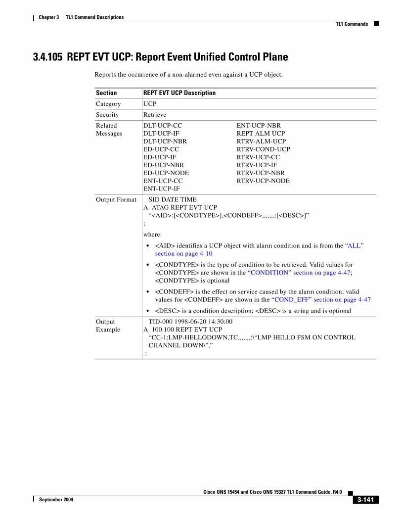
Chapter 3 TL1 Command DescriptionsTL1 Commands
3.4.105 REPT EVT UCP: Report Event Unified Control PlaneReports the occurrence of a non-alarmed even against a UCP object.
Section REPT EVT UCP Description
Category UCP
Security Retrieve
Related Messages
DLT-UCP-CC ENT-UCP-NBRDLT-UCP-IF REPT ALM UCPDLT-UCP-NBR RTRV-ALM-UCPED-UCP-CC RTRV-COND-UCPED-UCP-IF RTRV-UCP-CCED-UCP-NBR RTRV-UCP-IFED-UCP-NODE RTRV-UCP-NBRENT-UCP-CC RTRV-UCP-NODEENT-UCP-IF
Output Format SID DATE TIMEA ATAG REPT EVT UCP “<AID>:[<CONDTYPE>],<CONDEFF>,,,,,,,:[<DESC>]”;
where:
• <AID> identifies a UCP object with alarm condition and is from the “ALL” section on page 4-10
• <CONDTYPE> is the type of condition to be retrieved. Valid values for <CONDTYPE> are shown in the “CONDITION” section on page 4-47; <CONDTYPE> is optional
• <CONDEFF> is the effect on service caused by the alarm condition; valid values for <CONDEFF> are shown in the “COND_EFF” section on page 4-47
• <DESC> is a condition description; <DESC> is a string and is optional
Output Example
TID-000 1998-06-20 14:30:00A 100.100 REPT EVT UCP “CC-1:LMP-HELLODOWN,TC,,,,,,,:\“LMP HELLO FSM ON CONTROL CHANNEL DOWN\”,” ;
3-141Cisco ONS 15454 and Cisco ONS 15327 TL1 Command Guide, R4.0
September 2004

Chapter 3 TL1 Command DescriptionsTL1 Commands
3.4.106 REPT PM <MOD2>: Report Performance Monitoring (CLNT, DS1, EC1, OC12, OC192, OC3, OC48, OCH, STS1, STS12C, STS192C, STS24C, STS3C, STS48C, STS6C, STS9C, T1, T3, VT1)
See Table 4-11 on page 4-6 for supported modifiers by platform.
Reports autonomous monitoring statistics as a result of the schedule created by SCHED-PMREPT.
Section REPT PM <MOD2> Description
Category Performance
Security Retrieve
Related Messages
ALW-PMREPT-ALL RTRV-PMSCHED-ALLINH-PMREPT-ALL RTRV-PMSCHED-ALLINIT-REG-<MOD2> SCHED-PMREPT-<MOD2>RTRV-PM-<MOD2> SET-PMMODE-<STS_PATH>RTRV-PMMODE-<STS_PATH> SET-TH-<MOD2>RTRV-PMSCHED-<MOD2>
Output Format SID DATE TIMEA ATAG REPT PM <MOD2> “<AID>:<MONTYPE>,<MONVAL>,<VLDTY>,<LOCN>,<DIRN>, <TMPER>,<MONDAT>,<MONTM>”;
where:
• <AID> access identifier from the “ALL” section on page 4-10
• <MONTYPE> type of monitored parameter; valid values are shown in the “ALL_MONTYPE” section on page 4-33
• <MONVAL> measured value of monitored parameter; <MONVAL> is a string
• <VLDTY> validity indicator for the reported PM data; valid values for <VLDTY> are shown in the “VALIDITY” section on page 4-98
• <LOCN> indicates the location; valid values are shown in “LOCATION” section on page 4-71
• <DIRN> direction of PM relative to the entity identified by the AID; valid values are shown in the “DIRECTION” section on page 4-60
• <TMPER> indicates the accumulation time period for the PM data; valid values are shown in the “TMPER” section on page 4-93
• <MONDAT> is the date of the beginning of the PM period specified by the TMPER parameter; <MONDAT> is a string
• <MONTM> is the beginning time of day of the PM period specified by the TMPER parameter; <MONTM> is a string
Output Example
TID-000 1998-06-20 14:30:00A 100 REPT PM CLNT “FAC-3-1:CVL,10,PRTL,NEND,BTH,15-MIN,05-25,14-46”;
3-142Cisco ONS 15454 and Cisco ONS 15327 TL1 Command Guide, R4.0
September 2004

Chapter 3 TL1 Command DescriptionsTL1 Commands
3.4.107 REPT SW: Report Switch(Cisco ONS 15454 only)
Reports the autonomous switching of a unit in a duplex equipment pair to the standby state and its mate unit to the active state. An automatic report for the occurrence or clearance of an alarm or event that triggers the switch may be associated with the message.
3.4.108 RLS-EXT-CONT: Release External ControlThis command releases a forced contact state and returns the control of the contact to an AUTOMATIC control state. In AUTOMATIC control state, the contact could be opened or closed depending on triggers that may or may not be provisioned in the NE. Therefore, issuing an RLS might not produce any contact state change.
The NE defaults to having no triggers provisioned for external controls which consequently produces default open contacts. An NE with this default provisioning will always produce an open contact with a RLS-EXT-CONT command.
Notes:
1. The duration is not supported, it defaults to CONTS.
2. In an automatic state, the contact could be opened or closed depending on the provisioned trigger. Therefore, issuing an OPR-EXT-CONT command followed by an RLS-EXT-CONT command might not produce any contact state change.
Section REPT SW Description
Category path protection configuration switching
Security Retrieve
Related Messages
OPR-PROTNSW-<STS_PATH>OPR-PROTNSW-VT1RLS-PROTNSW-<STS_PATH>RLS-PROTNSW-VT1RTRV-PROTNSW-<STS_PATH>RTRV-PROTNSW-VT1
Output Format SID DATE TIMEA ATAG REPT SW “<ACTID>,<STDBYID>”;
where:
• <ACTID> identifies the equipment unit that has been placed in the active state. Parameter grouping cannot be used with this parameter; <ACTID> is the AID from the “EQPT” section on page 4-21
• <STDBYID> identifies the equipment unit that was placed in the standby state. Parameter grouping cannot be used with this parameter; <STDBYID> is the AID from the “EQPT” section on page 4-21
Output Example
TID-000 1998-06-20 14:30:00A 001 REPT SW “SLOT-8,SLOT-10”;
3-143Cisco ONS 15454 and Cisco ONS 15327 TL1 Command Guide, R4.0
September 2004

Chapter 3 TL1 Command DescriptionsTL1 Commands
3. The RLS-EXT-CONT is not allowed during the MNTRY duration. The command is allowed for the CONTS duration. The length of MNTRY duration is set to be 2 seconds.
3.4.109 RLS-LPBK-<MOD2>: Release Loopback (CLNT, DS1, EC1, OC12, OC192, OC3, OC48, OCH, STS1, STS12C, STS192C, STS24C, STS3C, STS48C, STS6C, STS9C, T1,T3, VT1)
See Table 4-11 on page 4-6 for supported modifiers by platform.
This command releases a signal loopback on an I/O card or a cross-connect.
Notes:
1. The value CRS for the LPBKTYPE parameter is applicable only for the STS modifier. The FACILITY and TERMINAL values for LPBKTYPE parameter are applicable to the ports.
2. The optional [<LPBKTYPE>] field defaults to the current existing loopback type.
3. The TERMINAL loopback type is not supported for a DS3XM card.
Section RLS-EXT-CONT Description
Category Environment Alarms and Controls
Security Maintenance
Related Messages
OPR-ACO-ALL RTRV-ATTR-ENVOPR-EXT-CONT RTRV-COND-ENVREPT ALM ENV RTRV-EXT-CONTREPT EVT ENV SET-ATTR-CONTRTRV-ALM-ENV SET-ATTR-ENVRTRV-ATTR-CONT
Input Format RLS-EXT-CONT:[<TID>]:<AID>:<CTAG>[::,];
where:
• <AID> identifies the external control being released and is from the “ENV” section on page 4-20
Input Example RLS-EXT-CONT:CISCO:ENV-OUT-2:123;
Errors Errors are listed in Table 7-30 on page 7-20.
Section RLS-LPBK-<MOD2> Description
Category Testing
Security Maintenance
Related Messages
OPR-LPBK-<MOD2>
Input Format RLS-LPBK-<MOD2>:[<TID>]:<SRC>:<CTAG>::,,,[<LPBKTYPE>];
where:
• <SRC> is an access identifier from the “DS1” section on page 4-20; valid values for AID are facility, DS1, and STS
• <LPBKTYPE> indicates the loopback type; valid values for <LPBKTYPE> are shown in the “LPBK_TYPE” section on page 4-71
3-144Cisco ONS 15454 and Cisco ONS 15327 TL1 Command Guide, R4.0
September 2004

Chapter 3 TL1 Command DescriptionsTL1 Commands
3.4.110 RLS-PROTNSW-<OCN_TYPE>: Release Protection Switch (OC3, OC12, OC48, OC192)
See Table 4-11 on page 4-6 for supported modifiers by platform.
This command releases a SONET line protection switch request.
The release of a protection switch request is applicable only to the OPR-PROTNSW protection switch commands, the user-initiated switch protection commands.
Notes:
1. This command is not used for the common control (TCC+/TCC2 or XC/XCVT/XC10G) cards. Sending a command on a common control card will generate an IIAC (Input, Invalid Access Identifier) error message. To query the common control card switching commands, use SW-DX-EQPT, ALW-SWDX-EQPT commands.
2. When sending this command on non-SONET (OCN) cards, an IIAC (Input, Invalid Access Identifier) error message should be responsed. To use this command on a non-SONET card switching command, use ALW-SWTOPROTN/SWTOWKG-EQPT and INH-SWTOPROTN/SWTOWKG-EQPT commands.
3. When sending this command to query on a card that is not in a protection group, the SNVS (Status, Not in Valid State) error message should be responsed.
4. When sending this command to a working card that is failed or missing, the SWFA (Status, Working unit Failed) error message should be responsed.
5. When sending this command to a protect card that is failed or missing, the SPFA (Status, Protection unit Failed) error message should be responsed.
6. When sending this command to a card that is not in protection, the SNPR (Status, Not in Protection State) error message should be responsed.
7. Sending this command to an OCN line that is already in clear mode will return a SAMS (Already in Clear Maintenance State) error message.
8. To get the protection switching state (manual, lockout, forced), use the RTRV-COND-ALL or RTRV-ALM-ALL command.
Input Example RLS-LPBK-DS1:PTREYES:DS1-4-1-2-13:203::,,,FACILITY;
Errors Errors are listed in Table 7-30 on page 7-20.
Section RLS-LPBK-<MOD2> Description (continued)
Section RLS-PROTNSW-<OCN_TYPE> Description
Category SONET Line Protection
Security Maintenance
Related Messages
DLT-FFP-<OCN_TYPE>ED-FFP-<OCN_TYPE>ENT-FFP-<OCN_TYPE>EX-SW-<OCN_TYPE>OPR-PROTNSW-<OCN_TYPE>RTRV-FFP-<OCN_TYPE>RTRV-PROTNSW-<OCN_TYPE>
3-145Cisco ONS 15454 and Cisco ONS 15327 TL1 Command Guide, R4.0
September 2004

Chapter 3 TL1 Command DescriptionsTL1 Commands
3.4.111 RLS-PROTNSW-<STS_PATH>: Release Protection Switch (STS1, STS3C, STS6C, STS9C, STS12C, STS24C, STS48C, STS192C)
See Table 4-11 on page 4-6 for supported modifiers by platform.
This command releases a SONET path protection switch request that was established with the OPR-PROTNSW-<STS_PATH> command. This command assumes that only one user-initiated switch is active per AID.
Notes:
1. This command applies to path protection configuration only.
2. The VTAID should be working or protect AID only.
3. If sending this command on the Drop AID, a DENY (Invalid AID, should use working/protect AID) message will be returned.
4. To get the protection switching state (manual, lockout, forced), use the RTRV-COND-ALL or RTRV-ALM-ALL command.
Input Format RLS-PROTNSW-<OCN_TYPE>:[<TID>]:<AID>:<CTAG>[::];
where:
• <AID> identifies the facility in the NE to which the switch request is directed and is from the “FACILITY” section on page 4-22
Input Example RLS-PROTNSW-OC48:PETALUMA:FAC-6-1:209;
Errors Errors are listed in Table 7-30 on page 7-20.
Section RLS-PROTNSW-<OCN_TYPE> Description (continued)
Section RLS-PROTNSW-<STS_PATH> Description
Category path protection configuration switching
Security Maintenance
Related Messages
OPR-PROTNSW-<STS_PATH>OPR-PROTNSW-VT1REPT SWRLS-PROTNSW-VT1RTRV-PROTNSW-<STS_PATH>RTRV-PROTNSW-VT1
Input Format RLS-PROTNSW-<STS_PATH>:[<TID>]:<AID>:<CTAG>[::];
where:
• <AID> identifies the entity in the NE to which the switch request is directed and is from the “STS” section on page 4-24
Input Example RLS-PROTNSW-STS1:CISCO:STS-2-1:123;
Errors Errors are listed in Table 7-30 on page 7-20.
3-146Cisco ONS 15454 and Cisco ONS 15327 TL1 Command Guide, R4.0
September 2004

Chapter 3 TL1 Command DescriptionsTL1 Commands
3.4.112 RLS-PROTNSW-CLNT: Release Protection Switch ClientThis command releases a Y cable protection switch on client facilities.
3.4.113 RLS-PROTNSW-VT1: Release Protection Switch VT1This command releases a SONET path protection switch request that was established with the OPR-PROTNSW-VT1 command. This command assumes that only one user-initiated switch is active per AID.
Notes:
1. This command applies to path protection configuration only.
2. The VTAID should be working or protect AID only.
3. Sending this command on the Drop AID, a DENY (Invalid AID, should use working/protect AID) message will be returned.
4. To get the protection switching state (manual, lockout, forced), use the RTRV-COND-ALL or RTRV-ALM-ALL command.
Section RLS-PROTNSW-CLNT Description
Category DWDM
Security Maintenance
Related Messages
OPR-PROTNSW-CLNTRTRV-FFP-CLNTED-FFP-CLNTED-DWDMRTRV-DWDMRTRV-COND-CLNTRTRV-ALM-CLNTRTRV-FFP-CLNTED-FFP-CLNTENT-FFP-CLNT
Input Format RLS-PROTNSW-CLNT:[<TID>]:<AID>:<CTAG>[::];
where:
• <AID> is from the “FACILITY” section on page 4-22
Input Example RLS-PROTNSW-CLNT:CISCO:FAC-1-1:100;
Errors Errors are listed in Table 7-30 on page 7-20.
Section RLS-PROTNSW-VT1 Description
Category path protection configuration switching
Security Maintenance
3-147Cisco ONS 15454 and Cisco ONS 15327 TL1 Command Guide, R4.0
September 2004

Chapter 3 TL1 Command DescriptionsTL1 Commands
3.4.114 RLS-SYNCNSW: Release Synchronization SwitchThis command releases the previous synchronization reference provided by the OPR-SYNCNSW command.
In a non-revertive system, the use of the RLS-SYNCNSW command may not be appropriate. All the switching between synchronization references should be initiated with the OPR-SYNCNSW command.
Once a switch is released, a minor alarm “MANSWTOPRI”, (Manual Switch to Primary Reference or Secondary...) or “FRDCSWTOPRI” (Forced Switch to Primary Reference or Secondary...), will be cleared.
Related Messages
OPR-PROTNSW-<STS_PATH>OPR-PROTNSW-VT1REPT SWRLS-PROTNSW-<STS_PATH>RTRV-PROTNSW-<STS_PATH>RTRV-PROTNSW-VT1
Input Format RLS-PROTNSW-VT1:[<TID>]:<AID>:<CTAG>[::];
where:
• <AID> identifies the entity in the NE to which the switch request is directed and is from the “VT1_5” section on page 4-30
Input Example RLS-PROTNSW-VT1:CISCO:VT1-4-2-3-1:123;
Errors Errors are listed in Table 7-30 on page 7-20.
Section RLS-PROTNSW-VT1 Description (continued)
Section RLS-SYNCNSW Description
Category Synchronization
Security Maintenance
Related Messages
ED-BITS RTRV-ALM-BITSED-NE-SYNCN RTRV-ALM-SYNCNED-SYNCN RTRV-BITSOPR-SYNCNSW RTRV-COND-BITSREPT ALM BITS RTRV-COND-SYNCNREPT ALM SYNCN RTRV-NE-SYNCNREPT EVT BITS RTRV-SYNCNREPT EVT SYNCN
Input Format RLS-SYNCNSW:[<TID>]:[<AID>]:<CTAG>;
where:
• <AID> is the access identifier from the “SYNC_REF” section on page 4-28. The default value is SYNC-NE.
Input Example RLS-SYNCNSW:CISCO:SYNC-NE:3;
Errors Errors are listed in Table 7-30 on page 7-20.
3-148Cisco ONS 15454 and Cisco ONS 15327 TL1 Command Guide, R4.0
September 2004

Chapter 3 TL1 Command DescriptionsTL1 Commands
3.4.115 RMV-<MOD2_IO>: Remove (CLNT, DS1, EC1, G1000, OC12, OC192, OC3, OC48, OCH, T1, T3)
See Table 4-11 on page 4-6 for supported modifiers by platform.
This command removes a facility from service.
3.4.116 RST-<MOD2_IO>: Restore (CLNT, DS1, EC1, G1000, OC12, OC192, OC3, OC48, OCH, T1, T3)
See Table 4-11 on page 4-6 for supported modifiers by platform.
This command provisions a facility in service.
Section RMV-<MOD2_IO> Description
Category Ports
Security Maintenance
Related Messages
ED-<OCN_TYPE> RTRV-DS1ED-DS1 RTRV-EC1ED-EC1 RTRV-FSTEED-G1000 RTRV-G1000ED-T1 RTRV-GIGEED-T3 RTRV-POSINIT-REG-G1000 RTRV-T1RST <MOD2_IO> RTRV-T3RTRV-<OCN_TYPE>
Input Format RMV-<MOD2_IO>:[<TID>]:<AID>:<CTAG>::[<CMDMODE>],[<PST>],[<SST>];
where:
• <AID> is the access identifier from the “ALL” section on page 4-10
• <CMDMODE> is the command mode; valid values are shown in the “CMD_MODE” section on page 4-46
• <PST> primary state; valid values are shown in the “PST” section on page 4-85
• <SST> secondary state; valid values are shown in the “SST” section on page 4-87
Input Example RMV-EC1:CISCO:FAC-1-1:1::NORM,OOS,AINS;
Errors Errors are listed in Table 7-30 on page 7-20.
Section RST-<MOD2_IO> Description
Category Ports
Security Maintenance
3-149Cisco ONS 15454 and Cisco ONS 15327 TL1 Command Guide, R4.0
September 2004

Chapter 3 TL1 Command DescriptionsTL1 Commands
3.4.117 RTRV-<OCN_TYPE>: Retrieve (OC3, OC12, OC48, OC192)See Table 4-11 on page 4-6 for supported modifiers by platform.
This command retrieves the attributes (i.e., service parameters) and the state of an OC-N facility.
Both RINGID and BLSRTYPE identify the OCN port connected with a BLSR. These attributes are only presented for the OC12, OC48, OC192 ports within a BLSR connection. The RTRV-BLSR command with the AID BLSR-RINGID, can provide more information on this BLSR.
Note This command does not show the WVLEN attribute if the OCN port has zero value on WVLELN.
UNI-C DCC provisioning notes:
1. The attributes DCC(Y/N) and mode (SONET/SDH) remain the same in the ED/RTRV-OCN commands when the DCC is used for UNI-C, in which case the port attribute UNIC is enabled (UNIC=Y).
2. UNI-C DCC termination ca not be deleted by the regular DCC de-provisioning command.
3. If the DCC is created under regular SONET provisioning, and this port is used by UNI-C, the port is converted as an UNI-C DCC automatically.
4. De-provisioning UNI-C IF/IB IPCC will free up DCC termination automatically.
Related Messages
ED-<OCN_TYPE> RTRV-DS1ED-DS1 RTRV-EC1ED-EC1 RTRV-FSTEED-G1000 RTRV-G1000ED-T1 RTRV-GIGEED-T3 RTRV-POSINIT-REG-G1000 RTRV-T1RMV <MOD2_IO> RTRV-T3RTRV-<OCN_TYPE>
Input Format RST-<MOD2_IO>:[<TID>]:<AID>:<CTAG>[::];
where:
• <AID> is an access identifier from the “ALL” section on page 4-10
Input Example RST-EC1:CISCO:FAC-1-1:1;
Errors Errors are listed in Table 7-30 on page 7-20.
Section RST-<MOD2_IO> Description (continued)
Section RTRV-<OCN_TYPE> Description
Category Ports
Security Retrieve
3-150Cisco ONS 15454 and Cisco ONS 15327 TL1 Command Guide, R4.0
September 2004

Chapter 3 TL1 Command DescriptionsTL1 Commands
Related Messages
ED-<OCN_TYPE> RST-<MOD2_IO>ED-DS1 RTRV-DS1ED-EC1 RTRV-EC1ED-G1000 RTRV-G1000ED-T1 RTRV-T1ED-T3 RTRV-T3RMV-<MOD2_IO>
Input Format RTRV-<OCN_TYPE>:[<TID>]:<AID>:<CTAG>[::::];
where:
• <AID> is the access identifier from the “FACILITY” section on page 4-22 and must not be null.
Input Example RTRV-OC48:PENNGROVE:FAC-6-1:236;
Output Format SID DATE TIMEM CTAG COMPLD “<AID>:,,[<ROLE>],[<STATUS>]:[DCC=<DCC>,][TMGREF=<TMGREF>,] [SYNCMSG=<SYNCMSG>,][SENDDUS=<SENDDUS>,] [PJMON=<PJMON>,][SFBER=<SFBER>,][SDBER=<SDBER>,] [MODE=<MODE>,][WVLEN=<WVLEN>,][RINGID=<RINGID>,] [BLSRTYPE=<BLSRTYPE>,][MUX=<MUX>,][UNIC=<UNIC>,] [CCID=<CCID>,][NBRIX=<NBRIX>,][SOAK=<SOAK>]: <PST>,[<SST>]”;
where:
• <AID> is the access identifier from the “FACILITY” section on page 4-22
• <ROLE> identifies the OCN port role (e.g. WORK or PROT); valid values for <ROLE> are shown in the “SIDE” section on page 4-87, <ROLE> is optional
• <STATUS> identifies the OCN port status (e.g. Active or Standby); valid values for <STATUS> are shown in the “STATUS” section on page 4-87, <STATUS> is optional
• <DCC> identifies the OCN port DCC connection and defaults to N; valid values for <DCC> are shown in the “ON_OFF” section on page 4-79, <DCC> is optional
• <TMGREF> identifies if an OCN port has timing reference and defaults to N; valid values for <TMGREF> are shown in the “ON_OFF” section on page 4-79, <TMGREF> is optional
• <SYNCMSG> indicates if sync status messaging is enabled or disabled on the facility; <SYNCMSG> defaults to Y and the valid values are shown in the “ON_OFF” section on page 4-79. <SYNCMSG> is optional.
• <SENDDUS> indicates that the facility will send out the DUS (do not use for synchronization) value as the sync status message for that facility; <SENDDUS> defaults to N and the valid values are shown in the “ON_OFF” section on page 4-79. <SENDDUS> is optional
• <PJMON> identifies the OCN port PJMON; <PJMON> defaults to 0 (zero), is an integer and is optional
Section RTRV-<OCN_TYPE> Description (continued)
3-151Cisco ONS 15454 and Cisco ONS 15327 TL1 Command Guide, R4.0
September 2004
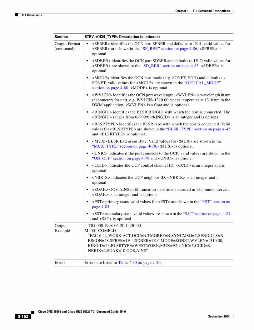
Chapter 3 TL1 Command DescriptionsTL1 Commands
Output Format (continued)
• <SFBER> identifies the OCN port SFBER and defaults to 1E-4; valid values for <SFBER> are shown in the “SF_BER” section on page 4-86, <SFBER> is optional
• <SDBER> identifies the OCN port SDBER and defaults to 1E-7; valid values for <SDBER> are shown in the “SD_BER” section on page 4-85, <SDBER> is optional
• <MODE> identifies the OCN port mode (e.g. SONET, SDH) and defaults to SONET; valid values for <MODE> are shown in the “OPTICAL_MODE” section on page 4-80, <MODE> is optional
• <WVLEN> identifies the OCN port wavelength; <WVLEN> is wavelength in nm (nanometer) for unit, e.g. WVLEN=1310.00 means it operates at 1310 nm in the DWM application. <WVLEN> is a float and is optional
• <RINGID> identifies the BLSR RINGID with which the port is connected. The <RINGID> ranges from 0–9999; <RINGID> is an integer and is optional
• <BLSRTYPE> identifies the BLSR type with which the port is connected. Valid values for <BLSRTYPE> are shown in the “BLSR_TYPE” section on page 4-43 and <BLSRTYPE> is optional.
• <MUX> BLSR Extension Byte. Valid values for <MUX> are shown in the “MUX_TYPE” section on page 4-78; <MUX> is optional.
• <UNIC> indicates if the port connects to the UCP; valid values are shown in the “ON_OFF” section on page 4-79 and <UNIC> is optional
• <CCID> indicates the UCP control channel ID; <CCID> is an integer and is optional
• <NBRIX> indicates the UCP neighbor ID. <NBRIX> is an integer and is optional
• <SOAK> OOS-AINS to IS transition soak time measured in 15 minute intervals. <SOAK> is an integer and is optional
• <PST> primary state; valid values for <PST> are shown in the “PST” section on page 4-85
• <SST> secondary state; valid values are shown in the “SST” section on page 4-87 and <SST> is optional
Output Example
TID-000 1998-06-20 14:30:00M 001 COMPLD “FAC-6-1:,,WORK,ACT:DCC=N,TMGREF=N,SYNCMSG=Y,SENDDUS=N, PJMON=48,SFBER=1E-4,SDBER=1E-6,MODE=SONET,WVLEN=1310.00, RINGID=43,BLSRTYPE=WESTWORK,MUX=E2,UNIC=Y,CCID=8, NBRIX=2,SOAK=10:OOS,AINS”;
Errors Errors are listed in Table 7-30 on page 7-20.
Section RTRV-<OCN_TYPE> Description (continued)
3-152Cisco ONS 15454 and Cisco ONS 15327 TL1 Command Guide, R4.0
September 2004

Chapter 3 TL1 Command DescriptionsTL1 Commands
3.4.118 RTRV-<STS_PATH>: Retrieve (STS1, STS3C, STS6C, STS9C, STS12C, STS24C, STS48C, STS192C)
See Table 4-11 on page 4-6 for supported modifiers by platform.
This command retrieves the attributes associated with an STS path.
The SFBER, SDBER, RVRTV, RVTM, SWPDIP, HOLDOFFTIMER, AND UPSRPTHSTATE parameters only apply to path protection configuration.
The path trace message is a 64 character string including the terminating CR (carriage return) and LF (line feed) that is transported in the J1 byte of the SONET STS Path overhead.
The EXPTRC indicates the contents of the expected incoming path trace are provisioned by the user in the ED-STS_PATH command. The TRC indicates the contents of the outgoing path trace message. The INCTRC indicates the contents of the incoming path trace message.
The path trace mode has three modes: OFF, MANUAL, and AUTO. The mode defaults to OFF. The MANUAL mode performs the comparison of the received string with the user entered expected string. The AUTO mode performs the comparison of the present received string with an expected string set to a previously received string. If there is a mismatch, the TIM-P alarm is raised. When the path trace mode is in OFF mode, there is no path trace processing, and all the alarm and state conditions are reset.
When the expected string is queried under the OFF path trace mode, the expected string is a copy of the provisioned string or NULL. When an expected string is queried under the MANUAL path trace mode, the expected string is a copy of the user entered string. When an expected string is queried under the AUTO path trace mode, the expected string is a copy of the acquired received string or NULL if the string has not been acquired.
When the incoming string is queried under the OFF path trace mode, the incoming string is NULL. When an incoming string is queried under the MANUAL or AUTO path trace mode, the incoming string is a copy of the received string or NULL if the string has not been received.
J1 (EXPTRC) is implemented on the DS1/DS1N, DS3E/DS3NE, DS3XM, EC1, OC3, OC48AS and OC192.
TRC and INCTRC are supported on DS1(N), DS3(N)E, and DS3XM cards.
Notes:
1. An optional parameter BLSRPTHTYPE is introduced into this command to provide more options to retrieve J1/C2 of a particular BLSR path. This field is valid only if the queried AID port has BLSR. The BLSRPTHTYPE defaults to “non-pca” path type if the BLSR is switched, or defaults to all BLSR path types if there is no BLSR switching.
2. Sending this command while BLSRPTHTYPE=PCA, whether there is BLSR switch or not, the PCA path J1/C2 data will be returned (if there is PCA circuit on the AID). Sending this command with an STS AID without circuits and no BLSR switched on the STS, an error message will be returned.
3. An optional output parameter BLSRPTHSTATE is introduced into this command output. Each J1/C2 output data of this command will include the BLSR path state information.
4. After the BLSR switching, the J1/IPPM/C2 data can be retrieved over the protection path, to provision J1 trace string, trace mode, or threshold is not allowed on the protection path.
Section RTRV-<STS_PATH> Description
Category STS and VT Paths
Security Retrieve
3-153Cisco ONS 15454 and Cisco ONS 15327 TL1 Command Guide, R4.0
September 2004

Chapter 3 TL1 Command DescriptionsTL1 Commands
Related Messages
ED-<STS_PATH>RTRV-PTHTRC-<STS_PATH>
Input Format RTRV-<STS_PATH>:[<TID>]:<AID>:<CTAG>:::[BLSRPTHTYPE=<BLSRPTHTYPE>][:];
where:
• <AID> is an access identifier from the “CrossConnectID” section on page 4-14 and must not be null
• <BLSRPTHTYPE> indicates the BLSR path type only if the port is on the BLSR. It defaults to “non-pca”. Valid values are shown in the “BLSR_PTH_TYPE” section on page 4-43. A null value defaults to “non-pca”
Input Example RTRV-STS1:FERNDALE:STS-2-1-4:238:::BLSRPTHTYPE=NON-PCA;
Output Format SID DATE TIMEM CTAG COMPLD “<AID>::[LEVEL=<LEVEL>,][SFBER=<SFBER>,][SDBER=<SDBER>,] [RVRTV=<RVRTV>,][RVTM=<RVTM>,][SWPDIP=<SWPDIP>,] [HOLDOFFTIMER=<HOLDOFFTIMER>,] [EXPTRC=<EXPTRC>,][TRC=<TRC>,][INCTRC=<INCTRC>,] [TRCMODE=<TRCMODE>,][TACC=<TACC>,] [UPSRPTHSTATE=<UPSRPTHSTATE>,][C2=<C2>,] [BLSRPTHSTATE=<BLSRPTHSTATE>]:[<PST>],[<SST>]”;
where:
• <AID> is an access identifier from the “CrossConnectID” section on page 4-14
• <LEVEL> indicates the rate of the cross connected channel; valid values for <LEVEL> are shown in the “STS_PATH” section on page 4-88, <LEVEL> is optional
• <SFBER> identifies the STS path SFBER which only applies to path protection configuration; <SFBER> defaults to 1E-4 and valid values are shown in the “SF_BER” section on page 4-86, <SFBER> is optional
• <SDBER> identifies the STS path SDBER which only applies to path protection configuration; <SDBER> defaults to 1E-6 and valid values are shown in the “SD_BER” section on page 4-85, <SDBER> is optional
• <RVRTV> identifies a revertive mode which only applies to path protection configuration and defaults to N (non-revertive mode) when a path protection configuration STSp is created; valid values for <RVRTV> are shown in the “ON_OFF” section on page 4-79 and <RVRTV> is optional
• <RVTM> identifies a revertive time which only applies to path protection configuration and defaults to empty because <RVRTV> is N when a path protection configuration STSp is created; valid values for <RVTM> are shown in the “REVERTIVE_TIME” section on page 4-85 and <RVTM> is optional
Section RTRV-<STS_PATH> Description (continued)
3-154Cisco ONS 15454 and Cisco ONS 15327 TL1 Command Guide, R4.0
September 2004

Chapter 3 TL1 Command DescriptionsTL1 Commands
Output Format (continued)
• Valid values for <SWPDIP> are shown in the “ON_OFF” section on page 4-79; <SWDIP> is optional
• <HOLDOFFTIMER> is an integer and is optional
• <EXPTRC> indicates the expected path trace message (J1) contents. The EXPTRC is any 64 character string, including the terminating CR (carriage return) and LF (line feed); <EXPTRC> defaults to null when a path protection configuration STSp is created. <EXPTRC> is a string and is optional
• <TRC> identifies the path trace message to be transmitted. The TRC is any combination of 64 characters, including the terminating CR (carriage return) and LF (line feed). The trace byte (J1) continuously transmits a 64 byte string, one byte at a time. A null value defaults to the NE transmitting null characters (Hex 00); <TRC> defaults to null when a path protection configuration STSp is created. <TRC> is a string and is optional
• <INCTRC> identifies the incoming path trace message contents. The INCTRC is any combination of 64 characters; <INCTRC> defaults to null when path protection configuration STSp is created. <INCTRC> is a string and is optional
• <TRCMODE> indicates the path trace mode, and defaults to the OFF mode when a path protection configuration STSp is created; valid values for <TRCMODE> are shown in the“TRCMODE” section on page 4-94 and <TRCMODE> is optional
• <TACC> is the AID from the “TACC” section on page 4-29 and is optional
• Valid values for <UPSRPTHSTATE> are shown in the “STATUS” section on page 4-87
• <C2> indicates C2 Byte Hex Code; valid values are shown in the “C2_BYTE” section on page 4-44
• <BLSRPTHSTATE> indicates the BLSR path state only if the port is on the BLSR; valid values are shown in the “BLSR_PTH_STATE” section on page 4-43
• <PST> primary state; valid values are shown in the “PST” section on page 4-85
• <SST> secondary state; valid values are shown in the “SST” section on page 4-87. <SST> is optional
Output Example
TID-000 1998-06-20 14:30:00M 001 COMPLD “STS-2-1-4::LEVEL=STS1,SFBER=1E-3,SDBER=1E-5,RVRTV=Y, RVTM=1.0,SWPDIP=Y,HOLDOFFTIMER=2000, EXPTRC=“EXPTRCSTRING”,TRC=“TRCSTRING”, INCTRC=“INCTRCSTRING”,TRCMODE=AUTO,TACC=8, UPSRPTHSTATE=ACT,C2=0X04, BLSRPTHSTATE=PROTPTHACT:OOS,AINS”;
Errors Errors are listed in Table 7-30 on page 7-20.
Section RTRV-<STS_PATH> Description (continued)
3-155Cisco ONS 15454 and Cisco ONS 15327 TL1 Command Guide, R4.0
September 2004

Chapter 3 TL1 Command DescriptionsTL1 Commands
3.4.119 RTRV-ALM-<MOD2ALM>:Retrieve Alarm (CLNT, DS1, E100, E1000, EC1, FSTE, G1000, GIGE, OC12, OC192, OC3, OC48, OCH, POS, STS1, STS12C, STS192C, STS24C, STS3C, STS48C, STS6C, STS9C, T1, T3, UDCDCC, UDCF, VT1)
See Table 4-11 on page 4-6 for supported modifiers by platform.
This command retrieves and sends the current status of alarm conditions. The alarm condition or severity to be retrieved can be specified by using the input parameters as a filter.
Notes:
1. VT1-n-n-n replaces PS_VT1-n-n-n for the VT1 alarm AID.
2. The [<AIDTYPE>] shows STS1 for STS alarms.
Section RTRV-ALM-<MOD2ALM> Description
Category Fault
Security Retrieve
Related Messages
REPT ALM <MOD2ALM> RTRV-ALM-EQPTREPT ALM BITS RTRV-ALM-RINGREPT ALM COM RTRV-ALM-SYNCNREPT ALM ENV RTRV-ALM-UCPREPT ALM EQPT RTRV-COND-<MOD2ALM>REPT ALM RING RTRV-COND-ALLREPT ALM SYNCN RTRV-COND-BITSREPT ALM UCP RTRV-COND-ENVREPT EVT COM RTRV-COND-EQPTRTRV-ALM-ALL RTRV-COND-RINGRTRV-ALM-BITS RTRV-COND-SYNCNRTRV-ALM-ENV RTRV-COND-UCP
Input Format RTRV-ALM-<MOD2ALM>:[<TID>]:<AID>:<CTAG>::[<NTFCNCDE>],[<CONDTYPE>],[<SRVEFF>][,,,];
where:
• <AID> is the access identifier from the “ALL” section on page 4-10 and must not be null
• <NTFCNCDE> is the 2-letter notification code; valid values for <NTFCNCDE> are shown in the “NOTIF_CODE” section on page 4-78. A null value is equivalent to ALL.
• <CONDTYPE> is the alarm condition; valid values for <CONDTYPE> are shown in the “CONDITION” section on page 4-47. A null value is equivalent to ALL.
• <SRVEFF> is the effect on service caused by the alarm condition; valid values for <SRVEFF> are shown in the “SERV_EFF” section on page 4-86. A null value is equivalent to ALL.
Input Example RTRV-ALM-OC12:ELDRIDGE:FAC-5-1:225::MN,SD,SA;
3-156Cisco ONS 15454 and Cisco ONS 15327 TL1 Command Guide, R4.0
September 2004

Chapter 3 TL1 Command DescriptionsTL1 Commands
3.4.120 RTRV-ALM-ALL: Retrieve Alarm AllThis command retrieves and sends the current status of all active alarm conditions. The alarm condition or severity to be retrieved is specified using the input parameters as a filter.
According to GR-833, the RTRV-ALM-ALL command only reports EQPT, RING, COM, and rr (T1, T3, OCN, EC1, STSN, VT1, and DS1) alarms.
To retrieve all the NE alarms, issue all of the following commands:
RTRV-ALM-ALLRTRV-ALM-ENVRTRV-ALM-BITSRTRV-ALM-RINGRTRV-ALM-SYNCN
Output Format SID DATE TIME M CTAG COMPLD “<AID>,[<AIDTYPE>]:<NTFCNCDE>,<CONDTYPE>,<SRVEFF>,,,,: [<DESC>]”;
where:
• <AID> is the access identifier from the “ALL” section on page 4-10
• <AIDTYPE> is the type of access identifier; valid values for <AIDTYPE> are shown in the “MOD2ALM” section on page 4-73, <AIDTYPE> is optional
• <NTFCNCDE> is the 2-letter notification code; valid values for <NTFCNCDE> are shown in the “NOTIF_CODE” section on page 4-78
• <CONDTYPE> is the alarm condition; valid values for <CONDTYPE> are shown in the “CONDITION” section on page 4-47
• <SRVEFF> is the effect on service caused by the alarm condition; valid values for <SRVEFF> are shown in the “SERV_EFF” section on page 4-86
• <DESC> is the condition description; <DESC> is a string and is optional
Output Example
TID-000 1998-06-20 14:30:00M 001 COMPLD “FAC-5-1,OC12:MJ,SD,SA,,,,:\“BER AT SIGNAL DEGRADE LEVEL\”,”;
Errors Errors are listed in Table 7-30 on page 7-20.
Section RTRV-ALM-<MOD2ALM> Description (continued)
Section RTRV-ALM-ALL Description
Category Fault
Security Retrieve
3-157Cisco ONS 15454 and Cisco ONS 15327 TL1 Command Guide, R4.0
September 2004

Chapter 3 TL1 Command DescriptionsTL1 Commands
Related Messages
REPT ALM <MOD2ALM> RTRV-ALM-EQPTREPT ALM BITS RTRV-ALM-RINGREPT ALM COM RTRV-ALM-SYNCNREPT ALM ENV RTRV-ALM-UCPREPT ALM EQPT RTRV-COND-<MOD2ALM>REPT ALM RING RTRV-COND-ALLREPT ALM SYNCN RTRV-COND-BITSREPT ALM UCP RTRV-COND-ENVREPT EVT COM RTRV-COND-EQPTRTRV-ALM-<MOD2ALM> RTRV-COND-RINGRTRV-ALM-BITS RTRV-COND-SYNCNRTRV-ALM-ENV RTRV-COND-UCP
Input Format RTRV-ALM-ALL:[<TID>]::<CTAG>::[<NTFCNCDE>],[<CONDITION>],[<SRVEFF>][,,,];
where:
• <NTFCNCDE> is a notification code; valid values for <NTFCNCDE> are shown in the “NOTIF_CODE” section on page 4-78. A null value is equivalent to ALL.
• <CONDITION> is the type of alarm condition; valid values for <CONDITION> are shown in the “CONDITION” section on page 4-47. A null value is equivalent to ALL.
• <SRVEFF> is the effect on service caused by the alarm condition; valid values for <SRVEFF> are shown in the “SERV_EFF” section on page 4-86. A null value is equivalent to ALL.
Input Example RTRV-ALM-ALL:COTATI::229::MN,PWRRESTART,NSA;
Output Format SID DATE TIME M CTAG COMPLD “[<AID>],[<AIDTYPE>]:<NTFCNCDE>,<CONDTYPE>,<SRVEFF>,,,,: [<DESC>],[<AIDDET>]”;
where:
• <AID> is the identifier that has an alarm condition and is from the “ALL” section on page 4-10, <AID> is optional
• <AIDTYPE> is the type of access identifier; valid values for <AIDTYPE> are shown in the “MOD2B” section on page 4-74, <AIDTYPE> is optional
• <NTFCNCDE> is the notification code; valid values for <NTFCNCDE> are shown in the “NOTIF_CODE” section on page 4-78
• <CONDTYPE> is the single type of alarm condition being reported on this particular line; valid values are shown in the “CONDITION” section on page 4-47
• <SRVEFF> is the effect on service caused by the alarm condition; valid values for <SRVEFF> are shown in the “SERV_EFF” section on page 4-86
• <DESC> is the condition description; <DESC> is a string and is optional
• <AIDDET> is the supplementary equipment identification; <AIDDET> is a string and is optional
Section RTRV-ALM-ALL Description (continued)
3-158Cisco ONS 15454 and Cisco ONS 15327 TL1 Command Guide, R4.0
September 2004

Chapter 3 TL1 Command DescriptionsTL1 Commands
3.4.121 RTRV-ALM-BITS: Retrieve Alarm Building Integrated Timing SupplyThis command retrieves and sends the current status of alarm conditions associated with the BITS facility. The alarm condition or severity retrieved is specified using the input parameters as a filter.
Output Example
TID-000 1998-06-20 14:30:00M 001 COMPLD “SLOT-2,EQPT:MN,PWRRESTART,NSA,,,,:\“POWER FAIL RESTART\”, DS1-14”;
Errors Errors are listed in Table 7-30 on page 7-20.
Section RTRV-ALM-ALL Description (continued)
Section RTRV-ALM-BITS Description
Category Synchronization
Security Retrieve
Related Messages
ED-BITS RTRV-ALM-ALLED-NE-SYNCN RTRV-ALM-ENVED-SYNCN RTRV-ALM-EQPTOPR-SYNCNSW RTRV-ALM-RINGREPT ALM <MOD2ALM> RTRV-ALM-SYNCNREPT ALM BITS RTRV-ALM-UCPREPT ALM COM RTRV-BITSREPT ALM ENV RTRV-COND-<MOD2ALM>REPT ALM EQPT RTRV-COND-ALLREPT ALM RING RTRV-COND-BITSREPT ALM SYNCN RTRV-COND-ENVREPT ALM UCP RTRV-COND-EQPTREPT EVT BITS RTRV-COND-RINGREPT EVT COM RTRV-COND-SYNCNREPT EVT SYNCN RTRV-COND-UCPRLS-SYNCNSW RTRV-NE-SYNCNRTRV-ALM-<MOD2ALM> RTRV-SYNCN
3-159Cisco ONS 15454 and Cisco ONS 15327 TL1 Command Guide, R4.0
September 2004

Chapter 3 TL1 Command DescriptionsTL1 Commands
Input Format RTRV-ALM-BITS:[<TID>]:<AID>:<CTAG>::[<NTFCNCDE>],[<CONDTYPE>],[<SRVEFF>][,,,];
where:
• <AID> is an identifier that has an alarm condition and is from the AID “BITS” section on page 4-18; <AID> must not be null
• <NTFCNCDE> is a 2-letter notification code; valid values for <NTFCNCDE> are shown in the “NOTIF_CODE” section on page 4-78. A null value is equivalent to ALL.
• <CONDTYPE> is an alarm condition; valid values for <CONDTYPE> are shown in the “CONDITION” section on page 4-47. A null value is equivalent to ALL.
• <SRVEFF> is the effect on service caused by the alarm condition; valid values for <SRVEFF> are shown in the “SERV_EFF” section on page 4-86. A null value is equivalent to ALL.
Input Example RTRV-ALM-BITS:ELVERANO:BITS-1:228::CR,LOS,SA;
Output Format SID DATE TIMEM CTAG COMPLD “<AID>,[<AIDTYPE>]:<NTFCNCDE>,<CONDTYPE>,<SRVEFF>,,,,: [<DESC>]”;
where:
• <AID> is the identifier that has an alarm condition and is from the “BITS” section on page 4-18
• <AIDTYPE> is the type of access identifier; valid values for <AIDTYPE> are shown in the “MOD2B” section on page 4-74 and <AIDTYPE> is optional
• <NTFCNCDE> is the 2-letter notification code; valid values for <NTFCNCDE> are shown in the “NOTIF_CODE” section on page 4-78
• <CONDTYPE> is the alarm condition; valid values for <CONDTYPE> are shown in the “CONDITION” section on page 4-47
• <SRVEFF> is the effect on service caused by the alarm condition; valid values for <SRVEFF> are shown in the “SERV_EFF” section on page 4-86
• <DESC> is the condition description; <DESC> is a string and is optional
Output Example
TID-000 1998-06-20 14:30:00M 001 COMPLD “BITS-1,BITS:CR,LOS,SA,,,,:\“LOSS OF SIGNAL\”,”;
Errors Errors are listed in Table 7-30 on page 7-20.
Section RTRV-ALM-BITS Description (continued)
3-160Cisco ONS 15454 and Cisco ONS 15327 TL1 Command Guide, R4.0
September 2004

Chapter 3 TL1 Command DescriptionsTL1 Commands
3.4.122 RTRV-ALM-ENV: Retrieve Alarm EnvironmentThis command retrieves the environmental alarms.
Section RTRV-ALM-ENV Description
Category Environment Alarms and Controls
Security Retrieve
Related Messages
OPR-ACO-ALL RTRV-ALM-RINGOPR-EXT-CONT RTRV-ALM-SYNCNREPT ALM <MOD2ALM> RTRV-ALM-UCPREPT ALM BITS RTRV-ATTR-CONTREPT ALM COM RTRV-ATTR-ENVREPT ALM ENV RTRV-COND-<MOD2ALM>REPT ALM EQPT RTRV-COND-ALLREPT ALM RING RTRV-COND-BITSREPT ALM SYNCN RTRV-COND-ENVREPT ALM UCP RTRV-COND-EQPTREPT EVT COM RTRV-COND-RINGREPT EVT ENV RTRV-COND-SYNCNRLS-EXT-CONT RTRV-COND-UCPRTRV-ALM-<MOD2ALM> RTRV-EXT-CONTRTRV-ALM-ALL SET-ATTR-CONTRTRV-ALM-BITS SET-ATTR-ENVRTRV-ALM-EQPT
Input Format RTRV-ALM-ENV:[<TID>]:<AID>:<CTAG>::[<NTFCNCDE>],[<ALMTYPE>];
where:
• <AID> is the access identifier from the “ENV” section on page 4-20; <AID> must not be null
Note For RTRV-ALM-ENV, only ENV-IN-{1-4} is a valid AID for ONS 15454 and only ENV-IN-{1-6} is a valid AID for ONS 15327. ENV-OUT-{1,6} is not a valid AID for RTRV-ALM-ENV.
• <NTFCNCDE> is a notification code; valid values for <NTFCNCDE> are shown in the “NOTIF_CODE” section on page 4-78. A null value is equivalent to ALL.
• <ALMTYPE> is the alarm type for the environmental alarm; valid values for <ALMTYPE> are shown in the “ENV_ALM” section on page 4-62. A null value is equivalent to ALL.
Input Example RTRV-ALM-ENV:CISCO:ENV-IN-1:123::MJ,OPENDR;
3-161Cisco ONS 15454 and Cisco ONS 15327 TL1 Command Guide, R4.0
September 2004

Chapter 3 TL1 Command DescriptionsTL1 Commands
3.4.123 RTRV-ALM-EQPT: Retrieve Alarm EquipmentThis command retrieves and sends the current status of alarm conditions associated with the equipment units. The alarm condition or severity to be retrieved is specified using the input parameters as a filter.
Output Format SID DATE TIMEM CTAG COMPLD “<AID>:<NTFCNCDE>,<ALMTYPE>,,,[<DESC>]”;
where:
• <AID> is an access identifier from the “ENV” section on page 4-20
• <NTFCNCDE> is the notification code; valid values for <NTFCNCDE> are shown in the “NOTIF_CODE” section on page 4-78
• <ALMTYPE> is the alarm type for the environmental alarm; valid values for <ALMTYPE> are shown in the “ENV_ALM” section on page 4-62
• <DESC> is the alarm message; <DESC> is a string and is optional
Output Example
TID-000 1998-06-20 14:30:00M 001 COMPLD “ENV-IN-1:MJ,OPENDR,,,\“OPEN DOOR\””;
Errors Errors are listed in Table 7-30 on page 7-20.
Section RTRV-ALM-ENV Description (continued)
Section RTRV-ALM-EQPT Description
Category Equipment
Security Retrieve
Related Messages
ALW-SWDX-EQPT RTRV-ALM-<MOD2ALM>ALW-SWTOPROTN-EQPT RTRV-ALM-ALLALW-SWTOWKG-EQPT RTRV-ALM-BITSDLT-EQPT RTRV-ALM-ENVED-EQPT RTRV-ALM-RINGENT-EQPT RTRV-ALM-SYNCNINH-SWDX-EQPT RTRV-ALM-UCPINH-SWTOPROTN-EQPT RTRV-COND-<MOD2ALM>INH-SWTOWKG-EQPT RTRV-COND-ALLREPT ALM <MOD2ALM> RTRV-COND-BITSREPT ALM BITS RTRV-COND-ENVREPT ALM COM RTRV-COND-EQPTREPT ALM ENV RTRV-COND-RINGREPT ALM EQPT RTRV-COND-SYNCNREPT ALM RING RTRV-COND-UCPREPT ALM SYNCN RTRV-EQPTREPT ALM UCP SW-DX-EQPTREPT ALM COM SW-TOPROTN-EQPTREPT EVT EQPT SW-TOWKG-EQPT
3-162Cisco ONS 15454 and Cisco ONS 15327 TL1 Command Guide, R4.0
September 2004

Chapter 3 TL1 Command DescriptionsTL1 Commands
Input Format RTRV-ALM-EQPT:[<TID>]:<AID>:<CTAG>::[<NTFCNCDE>],[<CONDTYPE>],[<SRVEFF>][,,,];
where:
• <AID> is an identifier that has an alarm condition and is from the “EQPT” section on page 4-21; <AID> must not be null
• <NTFCNCDE> is the 2-letter notification code; valid values for <NTFCNCDE> are shown in the “NOTIF_CODE” section on page 4-78. A null value is equivalent to ALL.
• <CONDTYPE> is the alarm condition; valid values for <CONDTYPE> are shown in the “CONDITION” section on page 4-47. A null value is equivalent to ALL.
• <SRVEFF> is the effect on service caused by the alarm condition; valid values for <SRVEFF> are shown in the “SERV_EFF” section on page 4-86. A null value is equivalent to ALL.
Input Example RTRV-ALM-EQPT:TWOROCK:SLOT-7:227::MJ,HITEMP,NSA;
Output Format SID DATE TIMEM CTAG COMPLD “[<AID>],[<AIDTYPE>]:<NTFCNCDE>,<CONDTYPE>,<SRVEFF>,,,,: [<DESC>]”;
where:
• <AID> is an identifier that has an alarm condition and is from the “EQPT” section on page 4-21; <AID> is optional
• valid values for <AIDTYPE> are shown in the “MOD2B” section on page 4-74; <AIDTYPE> is optional
• <NTFCNCDE> is a 2-letter notification code; valid values for <NTFCNCDE> are shown in the “NOTIF_CODE” section on page 4-78
• <CONDTYPE> is an alarm condition; valid values for <CONDTYPE> are shown in the “CONDITION” section on page 4-47
• <SRVEFF> is the effect on service caused by the alarm condition; valid values for <SRVEFF> are shown in the “SERV_EFF” section on page 4-86
• <DESC> is a condition description; <DESC> is a string and is optional
Output Example
TID-000 1998-06-20 14:30:00M 001 COMPLD “SLOT-7,EQPT:MJ,HITEMP,NSA,,,,:\“HI TEMPERATURE\”,”;
Errors Errors are listed in Table 7-30 on page 7-20.
Section RTRV-ALM-EQPT Description (continued)
3-163Cisco ONS 15454 and Cisco ONS 15327 TL1 Command Guide, R4.0
September 2004

Chapter 3 TL1 Command DescriptionsTL1 Commands
3.4.124 RTRV-ALM-RING: Retrieve Alarm RingThis command retrieves and sends the current status of all active alarm conditions against a ring object for BLSR. The alarm condition or severity to be retrieved can be specified by using the input parameters as a filter.
Section RTRV-ALM-RING Description
Category Fault
Security Retrieve
Related Messages
DLT-BLSR RTRV-ALM-BITSED-BLSR RTRV-ALM-ENVENT-BLSR RTRV-ALM-EQPTREPT ALM <MOD2ALM> RTRV-ALM-SYNCNREPT ALM BITS RTRV-ALM-UCPREPT ALM COM RTRV-BLSRREPT ALM ENV RTRV-COND-<MOD2ALM>REPT ALM EQPT RTRV-COND-ALLREPT ALM RING RTRV-COND-BITSREPT ALM SYNCN RTRV-COND-ENVREPT ALM UCP RTRV-COND-EQPTREPT EVT COM RTRV-COND-RINGREPT EVT RING RTRV-COND-SYNCNRTRV-ALM-<MOD2ALM> RTRV-COND-UCPRTRV-ALM-ALL
Input Format RTRV-ALM-RING:[<TID>]:[<AID>]:<CTAG>::[<NTFCNCDE>],[<CONDITION>],[<SRVEFF>][,,,];
where:
• <AID> identifies a BLSR RING ID with alarm condition and is the AID from the “BLSR” section on page 4-18; <AID> is a string and a null value is equivalent to ALL.
• <NTFCNCDE> is a notification code; valid values for <NTFCNCDE> are shown in the “NOTIF_CODE” section on page 4-78 and a null value is equivalent ALL.
• <CONDITION> indicates a BLSR alarm condition; valid values for <CONDITION> are shown in the “CONDITION” section on page 4-47 and a null value is equivalent to ALL.
• <SRVEFF> is the effect on service caused by the alarm condition; valid values for <SRVEFF> are shown in the “SERV_EFF” section on page 4-86 and a null value is equivalent to ALL.
Input Example RTRV-ALM-RING:CISCO:BLSR-999:123::MJ,PRC-DUPID,SA;
3-164Cisco ONS 15454 and Cisco ONS 15327 TL1 Command Guide, R4.0
September 2004

Chapter 3 TL1 Command DescriptionsTL1 Commands
3.4.125 RTRV-ALM-SYNCN: Retrieve Alarm Synchronization This command retrieves and sends the current status of alarm conditions associated with a synchronization facility. The alarm condition or severity to be retrieved can be specified by using the input parameters as a filter.
Output Format SID DATE TIMEM CTAG COMPLD “<AID>:<NTFCNCDE>,<CONDTYPE>,<SRVEFF>,,,,:[<DESC>]”;
where:
• <AID> identifies a BLSR RING ID with alarm condition and is from the “BLSR” section on page 4-18
• <NTFCNCDE> is a notification code; valid values for <NTFCNCDE> are shown in the “NOTIF_CODE” section on page 4-78
• <CONDTYPE> indicates a BLSR alarm condition; valid values for <CONDTYPE> are shown in the “CONDITION” section on page 4-47
• <SRVEFF> is the effect on service caused by the alarm condition; valid values for <SRVEFF> are shown in the “SERV_EFF” section on page 4-86
• <DESC> is a condition description; <DESC> is a string and is optional
Output Example
TID-000 1998-06-20 14:30:00M 001 COMPLD “BLSR-999:MJ,PRC-DUPID,SA,,,,:\“DUPLICATE NODE ID\”,”;
Errors Errors are listed in Table 7-30 on page 7-20.
Section RTRV-ALM-RING Description (continued)
Section RTRV-ALM-SYNCN Description
Category Synchronization
Security Retrieve
3-165Cisco ONS 15454 and Cisco ONS 15327 TL1 Command Guide, R4.0
September 2004

Chapter 3 TL1 Command DescriptionsTL1 Commands
Related Messages
ED-BITS RTRV-ALM-ALLED-NE-SYNCN RTRV-ALM-BITSED-SYNCN RTRV-ALM-ENVOPR-SYNCNSW RTRV-ALM-EQPTREPT ALM <MOD2ALM> RTRV-ALM-RINGREPT ALM BITS RTRV-ALM-UCPREPT ALM COM RTRV-BITSREPT ALM ENV RTRV-COND-<MOD2ALM>REPT ALM EQPT RTRV-COND-ALLREPT ALM RING RTRV-COND-BITSREPT ALM SYNCN RTRV-COND-ENVREPT ALM UCP RTRV-COND-EQPTREPT EVT BITS RTRV-COND-RINGREPT EVT COM RTRV-COND-SYNCNREPT EVT SYNCN RTRV-COND-UCPRLS-SYNCNSW RTRV-NE-SYNCNRTRV-ALM-<MOD2ALM> RTRV-SYNCN
Input Format RTRV-ALM-SYNCN:[<TID>]:<AID>:<CTAG>::[<NTFCNCDE>],[<CONDTYPE>],[<SRVEFF>][,,,];
where:
• <AID> identifies the access identifier from the “SYNC_REF” section on page 4-28, <AID> must not be null
• <NTFCNCDE> is the 2-letter notification code; valid values for <NTFCNCDE> are shown in the “NOTIF_CODE” section on page 4-78. A null value is equivalent to ALL.
• <CONDTYPE> is the alarm condition; valid values for <CONDTYPE> are shown in the “CONDITION” section on page 4-47. A null value is equivalent to ALL.
• <SRVEFF> is the effect on service caused by the alarm condition; valid values for <SRVEFF> are shown in the “SERV_EFF” section on page 4-86. A null value is equivalent to ALL.
Input Example RTRV-ALM-SYNCN:FULTON:SYNC-NE:226::CR,FAILTOSW,SA;
Section RTRV-ALM-SYNCN Description (continued)
3-166Cisco ONS 15454 and Cisco ONS 15327 TL1 Command Guide, R4.0
September 2004

Chapter 3 TL1 Command DescriptionsTL1 Commands
3.4.126 RTRV-ALM-UCP: Retrieve Alarm Unified Control PlaneThis retrieves and sends the current status of all active alarm conditions against a UCP object. The alarm condition or severity to be retrieved can be specified by using the input parameters as a filter.
Output Format SID DATE TIMEM CTAG COMPLD “<AID>,[<AIDTYPE>]:<NTFCNCDE>,<CONDTYPE>, <SRVEFF>,,,,:[<DESC>]”;
where:
• <AID> is the identifier that has an alarm condition and is from the “SYN” section on page 4-26
• <AIDTYPE> is the type of access identifier: valid values for <AIDTYPE> are shown in the “MOD2B” section on page 4-74 and <AIDTYPE> is optional
• <NTFCNCDE> is the 2-letter notification code; valid values for <NTFCNCDE> are shown in the “NOTIF_CODE” section on page 4-78
• <CONDTYPE> is the alarm condition; valid values for <CONDTYPE> are shown in the “CONDITION” section on page 4-47
• <SRVEFF> is the effect on service caused by the alarm condition; valid values for <SRVEFF> are shown in the “SERV_EFF” section on page 4-86
• <DESC> is the condition description; <DESC> is a string and is optional
Output Example
TID-000 1998-06-20 14:30:00M 001 COMPLD “SYNC-NE,SYNCN:CR,FAILTOSW,SA,,,,: \“FAILURE TO SWITCH TO PROTECTION\”,”;
Errors Errors are listed in Table 7-30 on page 7-20.
Section RTRV-ALM-SYNCN Description (continued)
Section RTRV-ALM-UCP Description
Category UCP
Security Retrieve
3-167Cisco ONS 15454 and Cisco ONS 15327 TL1 Command Guide, R4.0
September 2004

Chapter 3 TL1 Command DescriptionsTL1 Commands
Related Messages
DLT-UCP-CC RTRV-ALM-<MOD2ALM>DLT-UCP IF RTRV-ALM-ALLDLT-UCP-NBR RTRV-ALM-BITSED-UCP-CC RTRV-ALM-ENVED-UCP-IF RTRV-ALM-EQPTED-UCP-NBR RTRV-ALM-RINGED-UCP-NODE RTRV-ALM-SYNCNENT-UCP-CC RTRV-COND-<MOD2ALM>ENT-UCP-IF RTRV-COND-ALLENT-UCP-NBR RTRV-COND-BITSREPT ALM <MOD2ALM> RTRV-COND-ENVREPT ALM BITS RTRV-COND-EQPTREPT ALM COM RTRV-COND-RINGREPT ALM ENV RTRV-COND-SYNCNREPT ALM EQPT RTRV-COND-UCPREPT ALM RING RTRV-UCP-CCREPT ALM SYNCN RTRV-UCP-IFREPT ALM UCP RTRV-UCP-NBRREPT EVT COM RTRV-UCP-NODEREPT EVT UCP
Input Format RTRV-ALM-UCP:[<TID>]:<AID>:<CTAG>::[<NTFCNCDE>],[<CONDTYPE>],[<SRVEFF>][,,,];
where:
• <AID> identifies a UCP object with alarm condition; <AID> is from the “UCP” section on page 4-17 and must not be null
• <NTFCNCDE> is a notification code; valid values <NTFCNCDE> are shown in the “NOTIF_CODE” section on page 4-78. A null value is equivalent to ALL
• <CONDTYPE> is the type of condition to be retrieved; valid values are shown in the “CONDITION” section on page 4-47. A null value is equivalent to ALL
• <SRVEFF> is the effect on service caused by the alarm condition; valid values are shown in the “SERV_EFF” section on page 4-86. A null value is equivalent to ALL
Input Example RTRV-ALM-UCP:CISCO:CC-1:123::MJ,LMP-HELLODOWN,SA;
Section RTRV-ALM-UCP Description (continued)
3-168Cisco ONS 15454 and Cisco ONS 15327 TL1 Command Guide, R4.0
September 2004

Chapter 3 TL1 Command DescriptionsTL1 Commands
3.4.127 RTRV-ATTR-CONT: Retrieve Attribute ControlThis command retrieves and sends the attributes associated with an external control. These attributes are used when an external control is operated or released. To set these attributes, use the SET-ATTR-CONT command.
Output Format SID DATE TIMEM CTAG COMPLD “<AID>:<NTFCNCDE>,<CONDTYPE>,<SRVEFF>,,,,:[<DESC>]”;
where:
• <AID> identifies a UCP object with alarm condition; <AID> is from the “UCP” section on page 4-17
• <NTFCNCDE> is a notification code; valid values are shown in the “NOTIF_CODE” section on page 4-78
• <CONDTYPE> is the type of condition to be retrieved; valid values are shown in the “CONDITION” section on page 4-47
• <SRVEFF> is the effect on service caused by the alarm condition; valid values are shown in the “SERV_EFF” section on page 4-86
• <DESC> is a condition description; <DESC> is a string and is optional
Output Example
TID-000 1998-06-20 14:30:00M 001 COMPLD “CC-1:MJ,LMP-HELLODOWN,SA,,,,:\ “LMP HELLO FSM ON CONTROL CHANNEL DOWN\”,”;
Errors Errors are listed in Table 7-30 on page 7-20.
Section RTRV-ALM-UCP Description (continued)
Section RTRV-ATTR-CONT Description
Category Environment Alarms and Controls
Security Retrieve
Related Messages
OPR-EXT-CONT RTRV-ATTR-ENVREPT ALM ENV RTRV-COND-ENVREPT EVT ENV RTRV-EXT-CONTRLS-EXT-CONT SET-ATTR-CONTRTRV-ALM-ENV SET-ATTR-ENV
Input Format RTRV-ATTR-CONT:[<TID>]:<AID>:<CTAG>[::<CONTTYPE>];
where:
• <AID> identifies the external control for which attributes are being set; <AID> is from the “ENV” section on page 4-20 and must not be null
• <CONTTYPE> is the type of external control; valid values for <CONTTYPE> are shown in the “CONTTYPE” section on page 4-59. A null value is equivalent to ALL
Input Example RTRV-ATTR-CONT:CISCO:ENV-OUT-2:123::AIRCOND;
3-169Cisco ONS 15454 and Cisco ONS 15327 TL1 Command Guide, R4.0
September 2004

Chapter 3 TL1 Command DescriptionsTL1 Commands
3.4.128 RTRV-ATTR-ENV: Retrieve Attribute EnvironmentThis command retrieves the attributes associated with an environmental alarm.
Output Format SID DATE TIMEM CTAG COMPLD “<AID>:[<CONTTYPE>]”;
where:
• <AID> identifies the external control for which attributes are being set and is from the “ENV” section on page 4-20
• <CONTTYPE> is the type of external control; valid values are shown in the “CONTTYPE” section on page 4-59 and <CONTTYPE> is optional
Output Example
TID-000 1998-06-20 14:30:00M 001 COMPLD “ENV-OUT-2:AIRCOND”;
Errors Errors are listed in Table 7-30 on page 7-20.
Section RTRV-ATTR-CONT Description (continued)
Section RTRV-ATTR-ENV Description
Category Environment Alarms and Controls
Security Retrieve
Related Messages
OPR-EXT-CONT RTRV-ATTR-CONTREPT ALM ENV RTRV-COND-ENVREPT EVT ENV RTRV-EXT-CONTRLS-EXT-CONT SET-ATTR-CONTRTRV-ALM-ENV SET-ATTR-ENV
Input Format RTRV-ATTR-ENV:[<TID>]:<AID>:<CTAG>::[<NTFCNCDE>],[<ALMTYPE>];
where:
• <AID> is the access identifier from the “ENV” section on page 4-20 and must not be null
• <NTFCNCDE> is the notification code for the environmental alarm; valid values are shown in the “NOTIF_CODE” section on page 4-78. A null value is equivalent to ALL
• <ALMTYPE> is the alarm type for the environmental alarm; valid values are shown in the “ENV_ALM” section on page 4-62. A null value is equivalent to ALL
Input Example RTRV-ATTR-ENV:CISCO:ENV-IN-1:123::MJ,OPENDR;
3-170Cisco ONS 15454 and Cisco ONS 15327 TL1 Command Guide, R4.0
September 2004
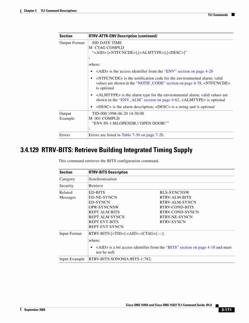
Chapter 3 TL1 Command DescriptionsTL1 Commands
3.4.129 RTRV-BITS: Retrieve Building Integrated Timing SupplyThis command retrieves the BITS configuration command.
Output Format SID DATE TIMEM CTAG COMPLD “<AID>:[<NTFCNCDE>],[<ALMTYPE>],[<DESC>]”;
where:
• <AID> is the access identifier from the “ENV” section on page 4-20
• <NTFCNCDE> is the notification code for the environmental alarm; valid values are shown in the “NOTIF_CODE” section on page 4-78, <NTFCNCDE> is optional
• <ALMTYPE> is the alarm type for the environmental alarm; valid values are shown in the “ENV_ALM” section on page 4-62, <ALMTYPE> is optional
• <DESC> is the alarm description; <DESC> is a string and is optional
Output Example
TID-000 1998-06-20 14:30:00M 001 COMPLD “ENV-IN-1:MJ,OPENDR,\“OPEN DOOR\””;
Errors Errors are listed in Table 7-30 on page 7-20.
Section RTRV-ATTR-ENV Description (continued)
Section RTRV-BITS Description
Category Synchronization
Security Retrieve
Related Messages
ED-BITS RLS-SYNCNSWED-NE-SYNCN RTRV-ALM-BITSED-SYNCN RTRV-ALM-SYNCNOPR-SYNCNSW RTRV-COND-BITSREPT ALM BITS RTRV-COND-SYNCNREPT ALM SYNCN RTRV-NE-SYNCNREPT EVT BITS RTRV-SYNCNREPT EVT SYNCN
Input Format RTRV-BITS:[<TID>]:<AID>:<CTAG>[::::];
where:
• <AID> is a bit access identifier from the “BITS” section on page 4-18 and must not be null
Input Example RTRV-BITS:SONOMA:BITS-1:782;
3-171Cisco ONS 15454 and Cisco ONS 15327 TL1 Command Guide, R4.0
September 2004

Chapter 3 TL1 Command DescriptionsTL1 Commands
Output Format SID DATE TIMEM CTAG COMPLD “<AID>::[LINECDE=<LINECDE>,][FMT=<FMT>,][LBO=<LBO>,] [SYNCMSG=<SYNCMSG>,][AISTHRSHLD=<AISTHRSHLD>]:[<PST>]”;
where:
• <AID> is an access identifier from the “BITS” section on page 4-18
• <LINECDE> is a line code; valid values for <LINECDE> are shown in the “LINE_CODE” section on page 4-70, <LINECDE> is optional
• <FMT> is a frame format; valid values are shown in the “FRAME_FORMAT” section on page 4-69, <FMT> is optional
• <LBO> indicates BITS line build-out; valid values are shown in the “BITS_LineBuildOut” section on page 4-42, <LBO> is optional
• <SYNCMSG> indicates a sync messaging; <SYNCMSG> defaults to (Y) and valid values are shown in the “ON_OFF” section on page 4-79, <SYNCMSG> is optional
• <AIRTHRSHLD> is the AIS threshold. Valid values are shown in the “SYNC_CLOCK_REF_QUALITY_LEVEL” section on page 4-89; <AIRTHRSHLD> is optional
• <PST> is the state; valid values are shown in the “PST” section on page 4-85, <PST> is optional
Output Example
TID-000 1998-06-20 14:30:00M 001 COMPLD “BITS-1::LINECDE=AMI,FMT=ESF,LBO=0-133,SYNCMSG=Y, AISTHRSHLD=PRS:IS”;
Errors Errors are listed in Table 7-30 on page 7-20.
Section RTRV-BITS Description (continued)
3-172Cisco ONS 15454 and Cisco ONS 15327 TL1 Command Guide, R4.0
September 2004

Chapter 3 TL1 Command DescriptionsTL1 Commands
3.4.130 RTRV-BLSR: Retrieve Bidirectional Line Switched RingThis command retrieves the BLSR information of the NE. A two-fiber or four-fiber BLSR can be retrieved.
Output examples:
4F BLSR
“BLSR-43::RINGID=43,NODEID=3,MODE=4F,RVRTV=Y,RVTM=5.0,SRVRTV=Y,SRVTM=5.0,EASTWORK=FAC-5-1,WESTWORK=FAC-6-1,EASTPROT=FAC-12-1,WESTPROT=FAC-13-1”
2F BLSR
“BLSR-12::RINGID=12,NODEID=2,MODE=2F,RVRTV=Y,RVTM=5.0,EASTWORK=FAC-5-1,WESTWORK=FAC-6-1”
Error conditions:
1. Only ALL, null, or single “BLSR-#” in the AID in is allowed in this command.
2. A NULL AID defaults to the AID ALL.
3. If the system fails on getting IOR, a SDBE (Status, Internal Data Base Error) error message will be returned.
4. If the NE does not have BSLR, the TL1 session will return the COMPLD error message with empty information to the user.
Section RTRV-BLSR Description
Category BLSR
Security Retrieve
Related Messages
DLT-BLSRED-BLSRENT-BLSRREPT ALM RINGREPT EVT RINGRTRV-ALM-RINGRTRV-COND-RING
Input Format RTRV-BLSR:[<TID>]:[<AID>]:<CTAG>[::::];
where:
• <AID> identifies the BLSR of the NE. Only ALL, NULL, or single “BLSR-#” in <AID> is allowed; <AID> is from the “BLSR” section on page 4-18. A null value is equivalent to ALL.
Input Example RTRV-BLSR:PETALUMA:ALL:123;
3-173Cisco ONS 15454 and Cisco ONS 15327 TL1 Command Guide, R4.0
September 2004

Chapter 3 TL1 Command DescriptionsTL1 Commands
Output Format SID DATE TIMEM CTAG COMPLD “[<AID>]::[RINGID=<RINGID>,][NODEID=<NODEID>,] [MODE=<MODE>,][RVRTV=<RVRTV>,][RVTM=<RVTM>,] [SRVRTV=<SRVRTV>,][SRVTM=<SRVTM>,] [EASTWORK=<EASTWORK>,][WESTWORK=<WESTWORK>,] [EASTPROT=<EASTPROT>,][WESTPROT=<WESTPROT>]”;
where:
• <AID> identifies the BLSR of the NE and is from the “BLSR” section on page 4-18
• <RINGID> identifies the BLSR ID of the NE and ranges from 0–9999; <RINGID> is an integer
• <NODEID> identifies the BLSR node ID of the NE and ranges from 0–31; <NODEID> is an integer
• <MODE> identifies the BLSR mode and can be 2-fiber or 4-fiber; valid values for <MODE> are shown in the “BLSR_MODE” section on page 4-42
• <RVRTV> identifies the revertive mode; valid values are shown in the “ON_OFF” section on page 4-79
• <RVTM> identifies the revertive time; valid values are shown in the “REVERTIVE_TIME” section on page 4-85
• <SRVRTV> identifies the span revertive mode; valid values are shown in the “ON_OFF” section on page 4-79 and <SRVRTV> is optional
• <SRVTM> identifies the span revertive time; valid values are shown in the “REVERTIVE_TIME” section on page 4-85. <SRVTM> is optional.
• <EASTWORK> identifies the east working facility and is the AID from the “FACILITY” section on page 4-22
• <WESTWORK> identifies the west working facility and is the AID from the “FACILITY” section on page 4-22
• <EASTPROT> identifies the east protecting facility and is the AID from the “FACILITY” section on page 4-22; <EASTPROT> is optional
• <WESTPROT> identifies the west protecting facility and is the AID from the “FACILITY” section on page 4-22; <WESTPROT> is optional
Output Example
TID-000 1998-06-20 14:30:00M 001 COMPLD “BLSR-43::RINGID=43,NODEID=3,MODE=4F,RVRTV=Y,RVTM=5.0, SRVRTV=Y,SRVTM=5.0,EASTWORK=FAC-5-1,WESTWORK=FAC-6-1, EASTPROT=FAC-12-1,WESTPROT=FAC-13-1”;
Errors Errors are listed in Table 7-30 on page 7-20.
Section RTRV-BLSR Description (continued)
3-174Cisco ONS 15454 and Cisco ONS 15327 TL1 Command Guide, R4.0
September 2004

Chapter 3 TL1 Command DescriptionsTL1 Commands
3.4.131 RTRV-CLNT: Retrieve ClientThis command retrieves client facility attributes.
See the “Provisioning Rules for MXP_2.5G_10G and TXP_MR_10G Cards” section on page 1-8 for specific MXP/TXP card provisioning rules.
Section RTRV-CLNT Description
Category DWDM
Security Retrieve
Related Messages
ED-CLNTRTRV-ALM-CLNTRTRV-COND-CLNTRST-CLNTRMV-CLNTED-DWDMRTRV-DWDM
Input Format RTRV-CLNT:[<TID>]:<AID>:<CTAG>;
where:
• <AID> is from the “FACILITY” section on page 4-22 and must not be null
Input Example RTRV-CLNT:CISCO:FAC-1-1:100;
Output Format SID DATE TIMEM CTAG COMPLD “<AID>:,,[<ROLE>],<STATUS>:[COMM=<COMM>,][SFBER=<SFBER>,] [SDBER=<SDBER>,][ALSMODE=<ALSMODE>,] [ALSRCINT=<ALSRCINT>,][ALSRCPW=<ALSRCPW>,] [SYNCMSG=<SYNCMSG>,][SENDDUS=<SENDDUS>,] [LSRSTAT=<LSRSTAT>,][CLEI=<CLEI>,][PN=<PARTNUM>,] [SN=<SERIALNUM>,][VENDOR=<VENDOR>,] [VENDORREV=<VENDORREV>,][OPTICS=<OPTICS>,] [MACADDR=<MACADDR>,][SOAK=<SOAK>]:<PST>,[<SST>]”;
where:
• <AID> is the facility AID from the “FACILITY” section on page 4-22
• <ROLE> identifies an OCn port role (i.e. WORK or PROT); valid values for are shown in the “SIDE” section on page 4-87
• <STATUS> identifies an OCn port status (i.e. Active or Standby); valid values are shown in the “STATUS” section on page 4-87
• <COMM> indicates if the GCC or DCC is enabled or disabled. The GCC can be enabled only if the digital wrapper has been enabled for the card. The default is NONE. Valid values are shown in the “COMM_TYPE” section on page 4-46. Rules for a MXP/TXP Client port are; only the DCC can be provisioned, if the termination mode is not transparent and the payload is SONET. On a MXP/TXP DWDM port, the DCC can be enabled only if the G.709 is not enabled and if the payload is SONET and the termination mode is not transparent. On a MXP/TXP DWDM port, the GCC can be enabled if there is no DCC and the G.709 flag is enabled.
3-175Cisco ONS 15454 and Cisco ONS 15327 TL1 Command Guide, R4.0
September 2004

Chapter 3 TL1 Command DescriptionsTL1 Commands
Output Format (continued)
• <SFBER> signal fail bit error ration that defaults to 1E-7; valid values are shown in the “SF_BER” section on page 4-86 and <SFBER> is optional
• <SDBER> signal degrade bit error ratio that defaults to 1E-7; valid values are shown in the “SD_BER” section on page 4-85 and <SDBER> is optional
• <ALSMODE> automatic laser shutdown mode that defaults to DISABLED; valid values are shown in the “ALS_MODE” section on page 4-41 and <ALSMODE> is optional
• <ALSRCINT> ALS interval; <ALSRCINT> is an integer and is optional
• <ALSRCPW> ALS pulse width; <ALSRCPW> is a float and is optional
• <SYNCMSG> indicates that the facility be enabled to provide the synchronization clock. This does not apply to a TXP card. This applies for a MXP card only if the payload is SONET/SDH and the card termination mode is as follows: TXP–no ports are available for timing selection. MXP–TRANSPARENT–all client ports are available for all timing selections. All trunk ports are not available. LINE–all ports are available for all timing selections. Valid values are shown in the “ON_OFF” section on page 4-79 and <SYNCMSG> is optional
• <SENDDUS> indicates that the facility be enabled to provide the synchronization clock. This does not apply to a TXP card. This applies for a MXP card only if the payload is SONET/SDH and the card termination mode is as follows: TXP–no ports are available for timing selection. MXP–TRANSPARENT–All client ports are available for all timing selections. All trunk ports are not available. LINE–All ports are available for all timing selections. Valid values are shown in the “ON_OFF” section on page 4-79 and <SENDDUS> is optional
• <LSRSTAT> indicates the laser status; valid values are shown in the “UP_DOWN” section on page 4-98 and <LSRSTAT> is optional
• <CLEI> is the CLEI code for the SFP for the MXP card; <CLEI> is a string and is optional
• <PARTNUM> is the part number for the SFP for the MXP card; <PARTNUM> is a string and is optional
• <SERIALNUM> is the serial number of the SFP for the MXP card; <SERIALNUM> is a string and is optional
• <VENDOR> is the vendor name for the SFP in a MXP card; <VENDOR> is a string and is optional
• <VENDORREV> is the vendor SFP revision number; <VENDORREV> is a string and is optional
Section RTRV-CLNT Description (continued)
3-176Cisco ONS 15454 and Cisco ONS 15327 TL1 Command Guide, R4.0
September 2004

Chapter 3 TL1 Command DescriptionsTL1 Commands
3.4.132 RTRV-COND-<MOD2ALM>: Retrieve Condition (CLNT, DS1, E100, E1000, EC1, FSTE, G1000, GIGE, OC12, OC192, OC3, OC48, OCH, POS, STS1, STS12C, STS192C, STS24C, STS3C, STS48C, STS6C, STS9C, T1, T3, UDCDCC, UDCF, VT1)
See Table 4-11 on page 4-6 for supported modifiers by platform.
This command retrieves the current standing condition and state associated with an entity.
Output Format (continued)
• <OPTICS> is the wavelength reach information for the SFP MXP card; <OPTICS> is a string and is optional
• <MACADDR> identifies the MAC address for the 10GE payload; <MACADDR> is a string and is optional
• <SOAK> OOS-AINS to IS transition soak time as measured in 15-minute intervals. A value of 4 equals a soak time of 1 hour. The allowable range is 0–480 intervals. <SOAK> is an integer and is optional
• <PST> is the primary state; valid values are shown in the “PST” section on page 4-85
• <SST> is the secondary state; valid values are shown in the “SST” section on page 4-87 and <SST> is optional
Output Example
TID-000 1998-06-20 14:30:00M 001 COMPLD “FAC-1-1:,,ROLE,ACT:COMM=DCC,SFBER=1E-4,SDBER=1E-6, ALSMODE=Y,ALSRCINT=30,ALSRCPW=35.1,SYNCMSG=Y,SENDDUS=Y, LSRSTAT=UP,CLEI=ABC,PN=123,SN=123,VENDOR=CISCO, VENDORREV=111,OPTICS=LR,MACADDR=00-11-22-33-44-55,SOAK=10: IS,AINS””;
Errors Errors are listed in Table 7-30 on page 7-20.
Section RTRV-CLNT Description (continued)
Section RTRV-COND-<MOD2ALM> Description
Category Fault
Security Retrieve
Related Messages
REPT ALM <MOD2ALM> RTRV-ALM-ENVREPT ALM BITS RTRV-ALM-EQPTREPT ALM COM RTRV-ALM-RINGREPT ALM ENV RTRV-ALM-SYNCNREPT ALM EQPT RTRV-ALM-UCPREPT ALM RING RTRV-COND-ALLREPT ALM SYNCN RTRV-COND-BITSREPT ALM UCP RTRV-COND-ENVREPT EVT COM RTRV-COND-EQPTRTRV-ALM-<MOD2ALM> RTRV-COND-RINGRTRV-ALM-ALL RTRV-COND-SYNCNRTRV-ALM-BITS RTRV-COND-UCP
3-177Cisco ONS 15454 and Cisco ONS 15327 TL1 Command Guide, R4.0
September 2004

Chapter 3 TL1 Command DescriptionsTL1 Commands
Input Format RTRV-COND-<MOD2ALM>:[<TID>]:<AID>:<CTAG>::[<TYPEREQ>][,,,];
where:
• <AID> is the identifier that has an alarm condition; <AID> is from the “ALL” section on page 4-10 and must not be null
• <TYPEREQ> is the type of condition to be retrieved; valid values are shown in the “CONDITION” section on page 4-47. A null value is equivalent to ALL.
Input Example RTRV-COND-T3:TID:FAC-2-1:229::LOS;
Output Format SID DATE TIMEM CTAG COMPLD “<AID>,[<AIDTYPE>]:[<NTFCNCDE>],<TYPEREP>,[<SRVEFF>], [<OCRDAT>],[<OCRTM>],,,[<DESC>]”;
where:
• <AID> is an identifier that has an alarm condition and is from the “ALL” section on page 4-10
• Valid values for <AIDTYPE> are shown in the “MOD2ALM” section on page 4-73, <AIDTYPE> is optional
• <NTFCNCDE> is a notification code; valid values are shown in the “NOTIF_CODE” section on page 4-78, <NTFCNCDE> is optional
• <TYPEREP> is the condition itself; valid values are shown in the “CONDITION” section on page 4-47
• <SRVEFF> is the effect on service caused by the alarm condition; valid values are shown in the “SERV_EFF” section on page 4-86, <SRVEFF> is optional
• <OCRDAT> is a date and is optional
• <OCRTM> is a time and is optional
• <DESC> is a condition description; <DESC> is a string and is optional
Output Example
TID-000 1998-06-20 14:30:00M 001 COMPLD “FAC-2-1,T3:CR,LOS,SA,01-01,16-00-20,,,\“LOS OF SIGNAL\””;
Errors Errors are listed in Table 7-30 on page 7-20.
Section RTRV-COND-<MOD2ALM> Description (continued)
3-178Cisco ONS 15454 and Cisco ONS 15327 TL1 Command Guide, R4.0
September 2004

Chapter 3 TL1 Command DescriptionsTL1 Commands
3.4.133 RTRV-COND-ALL: Retrieve Condition AllThis command retrieves the current standing condition for all entities.
According to GR-833, the RTRV-COND-ALL command only reports EQPT, COM, and rr (T1, T3, OCN, EC1, STSN, VT1, and DS1) alarms.
To retrieve all the NE conditions, issue all of the following commands:
RTRV-COND-ALLRTRV-COND-ENVRTRV-COND-BITSRTRV-COND-RINGRTRV-COND-SYNCN
RTRV-COND-ALL does not return all conditions that are returned by other, more specific RTRV-COND commands. Instead it returns a subset of those conditions. This is a requirement from section 6.2.1.8.4 of GR-253-CORE. The specific requirements are R6-288, R6-289 and R6-290. Section 6.2.1.8.4 states a retrieval that returns ALL conditions from a node (RTRV-COND-ALL) must omit any conditions that are “same root cause” as other raised conditions. The section also states any retrieval of a subset of the conditions from a node, regardless of how the subsetting occurs, should not omit these “same root cause” conditions. RTRV-COND-STS1, for example, must include “same root cause” conditions in the set it returns, while RTRV-COND-ALL must not.
Section RTRV-COND-ALL Description
Category Fault
Security Retrieve
Related Messages
REPT ALM <MOD2ALM> RTRV-ALM-ENVREPT ALM BITS RTRV-ALM-EQPTREPT ALM COM RTRV-ALM-RINGREPT ALM ENV RTRV-ALM-SYNCNREPT ALM EQPT RTRV-ALM-UCPREPT ALM RING RTRV-COND-<MOD2ALM>REPT ALM SYNCN RTRV-COND-BITSREPT ALM UCP RTRV-COND-ENVREPT EVT COM RTRV-COND-EQPTRTRV-ALM-<MOD2ALM> RTRV-COND-RINGRTRV-ALM-ALL RTRV-COND-SYNCNRTRV-ALM-BITS RTRV-COND-UCP
Input Format RTRV-COND-ALL:[<TID>]::<CTAG>::[<TYPEREQ>][,,,];
where:
• <TYPEREQ> is the type of condition to be retrieved; valid values are shown in the “CONDITION” section on page 4-47. A null value is equivalent to ALL
Input Example RTRV-COND-ALL:TID::229::LOS;
3-179Cisco ONS 15454 and Cisco ONS 15327 TL1 Command Guide, R4.0
September 2004

Chapter 3 TL1 Command DescriptionsTL1 Commands
Output Format SID DATE TIMEM CTAG COMPLD “<AID>,[<AIDTYPE>]:[<NTFCNCDE>],<TYPEREP>,[<SRVEFF>], [<OCRDAT>],[<OCRTM>],,,[<DESC>]”;
where:
• <AID> is an identifier that has an alarm condition; <AID> is from the “ALL” section on page 4-10
• <AIDTYPE> is the type of access identifier; valid values are shown in the “MOD2B” section on page 4-74, <AIDTYPE> is optional
• <NTFCNCDE> is the notification code; valid values are shown in the “NOTIF_CODE” section on page 4-78, <NTFCNCDE> is optional
• <TYPEREP> is the type of condition to be retrieved; valid values are shown in the “CONDITION” section on page 4-47
• <SRVEFF> is the effect on service caused by the alarm condition; valid values are shown in the “SERV_EFF” section on page 4-86, <SRVEFF> is optional
• <OCRDAT> is a date and is optional
• <OCRTM> is a time and is optional
• <DESC> is the condition description; <DESC> is a string and is optional
Output Example
TID-000 1998-06-20 14:30:00M 001 COMPLD “FAC-2-1,OC3:CR,LOS,SA,01-01,16-02-15,,,\“LOS OF SIGNAL\””;
Errors Errors are listed in Table 7-30 on page 7-20.
Section RTRV-COND-ALL Description (continued)
3-180Cisco ONS 15454 and Cisco ONS 15327 TL1 Command Guide, R4.0
September 2004

Chapter 3 TL1 Command DescriptionsTL1 Commands
3.4.134 RTRV-COND-BITS: Retrieve Condition Building Integrated Timing Supply
This command retrieves the standing conditions on BITS.
Section RTRV-COND-BITS Description
Category Synchronization
Security Retrieve
Related Messages
ED-BITS RTRV-ALM-ALLED-NE-SYNCN RTRV-ALM-BITSED-SYNCN RTRV-ALM-ENVOPR-SYNCNSW RTRV-ALM-EQPTREPT ALM <MOD2ALM> RTRV-ALM-RINGREPT ALM BITS RTRV-ALM-SYNCNREPT ALM COM RTRV-ALM-UCPREPT ALM ENV RTRV-BITSREPT ALM EQPT RTRV-COND-<MOD2ALM>REPT ALM RING RTRV-COND-ALLREPT ALM SYNCN RTRV-COND-ENVREPT ALM UCP RTRV-COND-EQPTREPT EVT BITS RTRV-COND-RINGREPT EVT COM RTRV-COND-SYNCNREPT EVT SYNCN RTRV-COND-UCPRLS-SYNCNSW RTRV-NE-SYNCNRTRV-ALM-<MOD2ALM> RTRV-SYNCN
Input Format RTRV-COND-BITS:[<TID>]:<AID>:<CTAG>::[<TYPEREQ>][,,,];
where:
• <AID> is the access identifier from the “BITS” section on page 4-18 and must not be null
• <TYPEREQ> is the type of condition to be retrieved; valid values are shown in the “CONDITION” section on page 4-47. A null value is equivalent to ALL
Input Example RTRV-COND-BITS:TID:BITS-1:229::LOS;
3-181Cisco ONS 15454 and Cisco ONS 15327 TL1 Command Guide, R4.0
September 2004

Chapter 3 TL1 Command DescriptionsTL1 Commands
Output Format SID DATE TIMEM CTAG COMPLD “<AID>,[<AIDTYPE>]:[<NTFCNCDE>],<TYPEREP>,[<SRVEFF>], [<OCRDAT>],[<OCRTM>],,,[<DESC>]”;
where:
• <AID> is an identifier that has an alarm condition and is from the “BITS” section on page 4-18
• <AIDTYPE> is the type of AID. It is always reported as BITS; valid values are shown in the “MOD2B” section on page 4-74, <AIDTYPE> is optional
• <NTFCNCDE> is the notification code; valid values are shown in the “NOTIF_CODE” section on page 4-78, <NTFCNCDE> is optional
• <TYPEREP> is the type of condition to be retrieved; valid values are shown in the “CONDITION” section on page 4-47
• <SRVEFF> is the effect on service caused by the alarm condition; valid values are shown in the “SERV_EFF” section on page 4-86, <SRVEFF> is optional
• <OCRDAT> is a date and is optional
• <OCRTM> is a time and is optional
• <DESC> is a string and is optional
Output Example
TID-000 1998-06-20 14:30:00M 001 COMPLD “BITS-1,BITS:CR,LOS,SA,01-01,16-02-15,,,\“LOS OF SIGNAL\””;
Errors Errors are listed in Table 7-30 on page 7-20.
Section RTRV-COND-BITS Description (continued)
3-182Cisco ONS 15454 and Cisco ONS 15327 TL1 Command Guide, R4.0
September 2004

Chapter 3 TL1 Command DescriptionsTL1 Commands
3.4.135 RTRV-COND-ENV: Retrieve Environmental ConditionThis command retrieves the environmental conditions.
Section RTRV-COND-ENV Description
Category Environment Alarms and Controls
Security Retrieve
Related Messages
OPR-EXT-CONT RTRV-ALM-EQPTREPT ALM <MOD2ALM> RTRV-ALM-RINGREPT ALM BITS RTRV-ALM-SYNCNREPT ALM COM RTRV-ALM-UCPREPT ALM ENV RTRV-ATTR-CONTREPT ALM EQPT RTRV-ATTR-ENVREPT ALM RING RTRV-COND-<MOD2ALM>REPT ALM SYNCN RTRV-COND-ALLREPT ALM UCP RTRV-COND-BITSREPT EVT COM RTRV-COND-EQPTREPT EVT ENV RTRV-COND-RINGRLS-EXT-CONT RTRV-COND-SYNCNRTRV-ALM-<MOD2ALM> RTRV-COND-UCPRTRV-ALM-ALL RTRV-EXT-CONTRTRV-ALM-BITS SET-ATTR-CONTRTRV-ALM-ENV SET-ATTR-ENV
Input Format RTRV-COND-ENV:[<TID>]:<AID>:<CTAG>::[<NTFCNCDE>],[<ALMTYPE>][,,,];
where:
• <AID> is an access identifier from the “ENV” section on page 4-20 and must not be null
Note For RTRV-COND-ENV, only ENV-IN-{1-4} is a valid AID for ONS 15454 and only ENV-IN-{1-6} is a valid AID for ONS 15327. ENV-OUT-{1,6} is not a valid AID for RTRV-COND-ENV.
• <NTFCNCDE> is a notification code; valid values are shown in the “NOTIF_CODE” section on page 4-78. A null value is equivalent to ALL.
• <ALMTYPE> is the condition type for the environmental conditions; valid values are shown in the “ENV_ALM” section on page 4-62. A null value is equivalent to ALL.
Input Example RTRV-COND-ENV:CISCO:ENV-IN-1:123::MJ,OPENDR;
3-183Cisco ONS 15454 and Cisco ONS 15327 TL1 Command Guide, R4.0
September 2004

Chapter 3 TL1 Command DescriptionsTL1 Commands
3.4.136 RTRV-COND-EQPT: Retrieve Condition EquipmentThis command retrieves the equipment conditions.
Output Format SID DATE TIMEM CTAG COMPLD “<AID>:<NTFCNCDE>,<ALMTYPE>,[<OCRDAT>], [<OCRTM>],,,,[<DESC>]”
;
where:
• <AID> is an access identifier and is from the “ENV” section on page 4-20
• <NTFCNCDE> is the notification code; valid values are shown in the “NOTIF_CODE” section on page 4-78
• <ALMTYPE> is an alarm type for the environmental alarm; valid values are shown in the “ENV_ALM” section on page 4-62
• <OCRDAT> is a date and is optional
• <OCRTM> is a time and is optional
• <DESC> is the description of the condition; <DESC> is a string and is optional
Output Example
TID-000 1998-06-20 14:30:00M 001 COMPLD “ENV-IN-1:MJ,OPENDR,01-01,16-02-15,,,,\“OPEN DOOR\””;
Errors Errors are listed in Table 7-30 on page 7-20.
Section RTRV-COND-ENV Description (continued)
Section RTRV-COND-EQPT Description
Category Equipment
Security Retrieve
3-184Cisco ONS 15454 and Cisco ONS 15327 TL1 Command Guide, R4.0
September 2004

Chapter 3 TL1 Command DescriptionsTL1 Commands
Related Messages
ALW-SWDX-EQPT RTRV-ALM-<MOD2ALM>ALW-SWTOPROTN-EQPT RTRV-ALM-ALLALW-SWTOWKG-EQPT RTRV-ALM-BITSDLT-EQPT RTRV-ALM-ENVED-EQPT RTRV-ALM-EQPTENT-EQPT RTRV-ALM-RINGINH-SWDX-EQPT RTRV-ALM-SYNCNINH-SWTOPROTN-EQPT RTRV-ALM-UCPINH-SWTOWKG-EQPT RTRV-COND-<MOD2ALM>REPT ALM <MOD2ALM> RTRV-COND-ALLREPT ALM BITS RTRV-COND-BITSREPT ALM COM RTRV-COND-ENVREPT ALM ENV RTRV-COND-RINGREPT ALM EQPT RTRV-COND-SYNCNREPT ALM RING RTRV-COND-UCPREPT ALM SYNCN RTRV-EQPTREPT ALM UCP SW-DX-EQPTREPT EVT COM SW-TOPROTN-EQPTREPT EVT EQPT SW-TOWKG-EQPT
Input Format RTRV-COND-EQPT:[<TID>]:<AID>:<CTAG>::[<TYPEREQ>][,,,];
where:
• <AID> is an identifier that has an alarm condition; <AID> is from the “EQPT” section on page 4-21 and must not be null
• <TYPEREQ> is the type of condition to be retrieved; valid values are shown in the “CONDITION” section on page 4-47. A null value is equivalent to ALL
Input Example RTRV-COND-EQPT:TID:SLOT-1:229::LOS;
Section RTRV-COND-EQPT Description (continued)
3-185Cisco ONS 15454 and Cisco ONS 15327 TL1 Command Guide, R4.0
September 2004

Chapter 3 TL1 Command DescriptionsTL1 Commands
Output Format SID DATE TIMEM CTAG COMPLD “<AID>,[<AIDTYPE>]:[<NTFCNCDE>],<TYPEREP>,[<SRVEFF>], [<OCRDAT>],[<OCRTM>],,,[<DESC>]”
;
where:
• <AID> is the identifier that has an alarm condition and is from the “EQPT” section on page 4-21
• <AIDTYPE> is the type of the AID. It is always reported as EQPT for the equipment condition; valid values are shown in the “MOD2B” section on page 4-74, <AIDTYPE> is optional
• <NTFCNCDE> is the notification code; valid values are shown in the “NOTIF_CODE” section on page 4-78, <NTFCNCDE> is optional
• <TYPEREP> is the type of condition to be retrieved; valid values are shown in the “CONDITION” section on page 4-47
• <SRVEFF> is the effect on service caused by the alarm condition; valid values are shown in the “SERV_EFF” section on page 4-86, <SRVEFF> is optional
• <OCRDAT> is a date and is optional
• <OCRTM> is a time and is optional
• <DESC> is the condition description; <DESC> is a string and is optional
Output Example
TID-000 1998-06-20 14:30:00M 001 COMPLD “SLOT-1,EQPT:CR,LOS,SA,01-01,16-02-15,,,\“LOS OF SIGNAL\””;
Errors Errors are listed in Table 7-30 on page 7-20.
Section RTRV-COND-EQPT Description (continued)
3-186Cisco ONS 15454 and Cisco ONS 15327 TL1 Command Guide, R4.0
September 2004

Chapter 3 TL1 Command DescriptionsTL1 Commands
3.4.137 RTRV-COND-RING: Retrieve Condition RingThis command retrieves the current standing condition against a ring object for BLSR. The condition BLSR-UPDATED has been added and is always reported as a transient message, not a standing condition/alarm.
Note When a change is made to a BLSR, including creating a new circuit, the circuit will not have BLSR protection until after the BLSR-UPDATED message is received.
Section RTRV-COND-RING Description
Category BLSR
Security Retrieve
Related Messages
DLT-BLSR RTRV-ALM-BITSED-BLSR RTRV-ALM-ENVENT-BLSR RTRV-ALM-EQPTREPT ALM <MOD2ALM> RTRV-ALM-RINGREPT ALM BITS RTRV-ALM-UCPREPT ALM COM RTRV-ALM-SYNCNREPT ALM ENV RTRV-BLSRREPT ALM EQPT RTRV-COND-<MOD2ALM>REPT ALM RING RTRV-COND-ALLREPT ALM SYNCN RTRV-COND-BITSREPT ALM UCP RTRV-COND-ENVREPT EVT COM RTRV-COND-EQPTREPT EVT RING RTRV-COND-SYNCNRTRV-ALM-<MOD2ALM> RTRV-COND-UCPRTRV-ALM-ALL
Input Format RTRV-COND-RING:[<TID>]:[<AID>]:<CTAG>::[<TYPEREQ>][,,,];
where:
• <AID> identifies a BLSR ID with alarm condition; <AID> is a string and a null value is equivalent to ALL
• Valid values for <TYPEREQ> are shown in the “CONDITION” section on page 4-47 and a null value is equivalent to ALL
Input Example RTRV-COND-RING:CISCO:RING-88:123::RING-MISMATCH;
3-187Cisco ONS 15454 and Cisco ONS 15327 TL1 Command Guide, R4.0
September 2004

Chapter 3 TL1 Command DescriptionsTL1 Commands
3.4.138 RTRV-COND-SYNCN: Retrieve Condition SynchronizationThis command retrieves the synchronization condition.
Output Format SID DATE TIMEM CTAG COMPLD “<AID>:[<NTFCNCDE>],<TYPEREP>,[<SRVEFF>],[<OCRDAT>], [<OCRTM>],,,[<DESC>]”;
where:
• <AID> identifies a BLSR ID with alarm condition; <AID> is from the “BLSR” section on page 4-18
• Valid values for <NTFCNCDE> are shown in the “NOTIF_CODE” section on page 4-78. <NTFCNCDE> is optional.
• Valid values for <TYPEREP> are shown in the “CONDITION” section on page 4-47
• <SRVEFF> is the effect on service caused by the alarm condition; valid values are shown in the “SERV_EFF” section on page 4-86. <SRVEFF> is optional.
• <OCRDAT> is a date and is optional
• <OCRTM> is a time and is optional
• <DESC> is a string and is optional
Output Example
TID-000 1998-06-20 14:30:00M 001 COMPLD “BLSR-88:MN,RING-MISMATCH,SA,01-01,16-02-15,,, \“FAR END OF FIBER IS PROVISIONED WITH DIFFERENT RING ID\”,”;
Errors Errors are listed in Table 7-30 on page 7-20.
Section RTRV-COND-RING Description (continued)
Section RTRV-COND-SYNCN Description
Category Synchronization
Security Retrieve
3-188Cisco ONS 15454 and Cisco ONS 15327 TL1 Command Guide, R4.0
September 2004

Chapter 3 TL1 Command DescriptionsTL1 Commands
Related Messages
ED-BITS RTRV-ALM-ALLED-NE-SYNCN RTRV-ALM-BITSED-SYNCN RTRV-ALM-ENVOPR-SYNCNSW RTRV-ALM-EQPTREPT ALM <MOD2ALM> RTRV-ALM-RINGREPT ALM BITS RTRV-ALM-SYNCNREPT ALM COM RTRV-ALM-UCPREPT ALM ENV RTRV-BITSREPT ALM EQPT RTRV-COND-<MOD2ALM>REPT ALM RING RTRV-COND-ALLREPT ALM SYNCN RTRV-COND-BITSREPT ALM UCP RTRV-COND-ENVREPT EVT BITS RTRV-COND-EQPTREPT EVT COM RTRV-COND-RINGREPT EVT SYNCN RTRV-COND-UCPRLS-SYNCNSW RTRV-NE-SYNCNRTRV-ALM-<MOD2ALM> RTRV-SYNCN
Input Format RTRV-COND-SYNCN:[<TID>]:<AID>:<CTAG>::[<TYPEREQ>][,,,];
where:
• <AID> is an identifier that has an alarm condition; <AID> is from the “SYNC_REF” section on page 4-28 and must not be null
• <TYPEREQ> is the type of condition to be retrieved; valid values are shown in the “CONDITION” section on page 4-47. A null value is equivalent to ALL
Input Example RTRV-COND-SYNCN:TID:SYNC-NE:229::LOS;
Output Format SID DATE TIMEM CTAG COMPLD “<AID>,[<AIDTYPE>]:[<NTFCNCDE>],<TYPEREP>,[<SRVEFF>], [<OCRDAT>],[<OCRTM>],,,[<DESC>]”;
where:
• <AID> is the identifier that has an alarm condition and is from the “SYN” section on page 4-26
• <AIDTYPE> is the type of AID. It is always reported as SYNCN; valid values are shown in the “MOD2B” section on page 4-74, <AIDTYPE> is optional
• <NTFCNCDE> is the notification code; valid values for <NTFCNCDE> are shown in the “NOTIF_CODE” section on page 4-78, <NTFCNCDE> is optional
• <TYPEREP> is the type of condition to be retrieved; valid values are shown in the “CONDITION” section on page 4-47
• <SRVEFF> is the effect on service caused by the alarm condition; valid values are shown in the “SERV_EFF” section on page 4-86, <SRVEFF> is optional
• <OCRDAT> is a date and is optional
• <OCRTM> is a time and is optional
• <DESC> is the condition description; <DESC> is a string and is optional
Section RTRV-COND-SYNCN Description (continued)
3-189Cisco ONS 15454 and Cisco ONS 15327 TL1 Command Guide, R4.0
September 2004

Chapter 3 TL1 Command DescriptionsTL1 Commands
3.4.139 RTRV-COND-UCP: Retrieve Condition Unified Control PlaneThis command retrieves the current standing condition against a UCP object.
Output Example
TID-000 1998-06-20 14:30:00M 001 COMPLD “SYNC-NE,SYNCN:MJ,FRNGSYNC,SA,01-01,16-02-15,,, \“FREE RUNNING SYNCHRONIZATION MODE\””;
Errors Errors are listed in Table 7-30 on page 7-20.
Section RTRV-COND-SYNCN Description (continued)
Section RTRV-COND-UCP Description
Category UCP
Security Retrieve
Related Messages
DLT-UCP-CC RTRV-ALM-<MOD2ALM>DLT-UCP IF RTRV-ALM-ALLDLT-UCP-NBR RTRV-ALM-BITSED-UCP-CC RTRV-ALM-ENVED-UCP-IF RTRV-ALM-EQPTED-UCP-NBR RTRV-ALM-RINGED-UCP-NODE RTRV-ALM-SYNCNENT-UCP-CC RTRV-ALM-UCPENT-UCP-IF RTRV-COND-<MOD2ALM>ENT-UCP-NBR RTRV-COND-ALLREPT ALM <MOD2ALM> RTRV-COND-BITSREPT ALM BITS RTRV-COND-ENVREPT ALM COM RTRV-COND-EQPTREPT ALM ENV RTRV-COND-RINGREPT ALM EQPT RTRV-COND-SYNCNREPT ALM RING RTRV-UCP-CCREPT ALM SYNCN RTRV-UCP-IFREPT ALM UCP RTRV-UCP-NBRREPT EVT COM RTRV-UCP-NODEREPT EVT UCP
Input Format RTRV-COND-UCP:[<TID>]:<AID>:<CTAG>::[<TYPEREQ>][,,,];
where:
• <AID> identifies a UCP object with alarm condition; <AID> is from the “UCP” section on page 4-17 and must not be NULL
• <TYPEREQ> is the type of condition to be retrieved; valid values are shown in the “CONDITION” section on page 4-47 and a NULL value is equivalent to ALL
Input Example RTRV-COND-UCP:CISCO:CC-18:123::LMP-HELLODOWN;
3-190Cisco ONS 15454 and Cisco ONS 15327 TL1 Command Guide, R4.0
September 2004

Chapter 3 TL1 Command DescriptionsTL1 Commands
3.4.140 RTRV-CRS: Retrieve Cross ConnectThis command retrieves all the cross-connections based on the required CRSTYPE (for all STS connections), STS1, STS3C, STS6C, STS9C, STS12C, STS24C, STS48C, STS192C and VT).
Notes:
1. A NULL AID defaults to ALL (NE).
2. A NULL CRSTYPE defaults to all the existing cross-connections.
3. The level in the output field is an optional field, and is used to indicate the bandwidth of the STS cross-connection.
Output Format SID DATE TIMEM CTAG COMPLD “<AID>:[<NTFCNCDE>],<TYPEREP>,[<SRVEFF>],[<OCRDAT>], [<OCRTM>],,,[<DESC>]”;
where:
• <AID> identifies a UCP object with alarm condition; <AID> is from the “UCP” section on page 4-17
• <NTFCNCDE> is a notification code; valid values are shown in the “NOTIF_CODE” section on page 4-78 and <NTFCNCDE> is optional
• <TYPEREP> is the type of condition to be retrieved; valid values are shown in the “CONDITION” section on page 4-47
• <SRVEFF> is the effect on service caused by the alarm condition; valid values are shown in the “SERV_EFF” section on page 4-86 and <SRVEFF> is optional
• <OCRDAT> is a date and is optional
• <OCRTM> is a time and is optional
• <DESC> is a condition description, a string and is optional
Output Example
TID-000 1998-06-20 14:30:00M 001 COMPLD “CC-18:MN,LMP-HELLODOWN,SA,01-01,16-02-15,,, \“LMP HELLO FSM ON CONTROL CHANNEL DOWN\“,”;
Errors Errors are listed in Table 7-30 on page 7-20.
Section RTRV-COND-UCP Description (continued)
Section RTRV-CRS Description
Category Cross Connections
Security Retrieve
Related Messages
DLT-CRS-<STS_PATH> ENT-CRS-<STS_PATH>DLT-CRS-VT1 ENT-CRS-VT1ED-CRS-<STS_PATH> RTRV-CRS-<STS_PATH>ED-CRS-VT1 RTRV-CRS-VT1
3-191Cisco ONS 15454 and Cisco ONS 15327 TL1 Command Guide, R4.0
September 2004

Chapter 3 TL1 Command DescriptionsTL1 Commands
Input Format RTRV-CRS:[<TID>]:<AID>:<CTAG>:::[CRSTYPE=<CRSTYPE>][:];
where:
• <AID> indicates the access identifier. It can be a facility AID, an STS AID, a VT AID, or ALL AID. The ALL AID defaults to NE, which reports all the existing cross-connections of the NE. <AID> is from the “ALL” section on page 4-10 and must not be NULL
• <CRSTYPE> specifies the cross-connection type. It is STS or VT or both. It defaults to all existing cross-connections. Valid values for <CRSTYPE> are shown in the “CRS_TYPE” section on page 4-60 and a NULL value is equivalent to ALL
Input Example RTRV-CRS:CISCO:ALL:123:::CRSTYPE=STS;
Output Format SID DATE TIMEM CTAG COMPLD “<FROM>,<TO>:<CCT>,<MOD>::<PST>,[<SST>]”;
where:
• <FROM> identifies an entity at one end of the cross-connection; <FROM> is from the “ALL” section on page 4-10
• <TO> identifies an entity at the other end of the cross-connection; <TO> is from the “ALL” section on page 4-10
• <CCT> identifies the cross-connection type; valid values are shown in the “CCT” section on page 4-45
• Valid values for <MOD> are shown in the “MOD2” section on page 4-72
• <PST> primary state; valid values are shown in the “PST” section on page 4-85
• <SST> secondary state; valid values are shown in the “SST” section on page 4-87 and <SST> is optional
Output Example
TID-000 1998-06-20 14:30:00M 001 COMPLD “STS-6-1,STS-12-4:2WAY,STS3C::OOS,AINS”;
Errors Errors are listed in Table 7-30 on page 7-20.
Section RTRV-CRS Description (continued)
3-192Cisco ONS 15454 and Cisco ONS 15327 TL1 Command Guide, R4.0
September 2004

Chapter 3 TL1 Command DescriptionsTL1 Commands
3.4.141 RTRV-CRS-<STS_PATH>: Retrieve Cross Connect (STS1, STS3C, STS6C, STS9C, STS12C, STS24C, STS48C, STS192C)
See Table 4-11 on page 4-6 for supported modifiers by platform.
This command retrieves any connections associated with the entered AID(s) or AID range. The information on both ends is returned along with the type of connection.
Notes:
1. The path protection configuration STS cross-connection can be retrieved by using “&” in the AID fields of this command.
a. To retrieve a 1-way selector or 2-way selector and bridge cross-connection with:
from points: F1, F2
to points: T1
the output will be:
1-way
“F1&F2,T1:CCT,STS3C”
2-way
If retrieved on point F1 or F2, the output format is the same as the 1-way output.
If retrieved on point T1, the output will be:
“T1,F1&F2:CCT,STS3C”
b. To retrieve a 1-way bridge or 2-way selector and bridge cross-connection with:
from point: F1
to points: T1, T2
the output will be:
1-way
“F1,T1&T2:CCT,STS3C”
2-way
“T1&T2,F1:CCT,STS3C”
c. To retrieve a 1-way subtending path protection configuration connection or 2-way subtending path protection configuration cross-connection with:
from point: F1, F2
to points: T1, T2
the output will be:
1-way:
“F1&F2,T1&T2:CCT,STS3C”
2-way:
If retrieved on point F1 or F2, the output format is the same as the 1-way output.
If retrieved on point T1 or T2, the output will be:
“T1&T2,F1&F2:CCT,STS3C”
3-193Cisco ONS 15454 and Cisco ONS 15327 TL1 Command Guide, R4.0
September 2004

Chapter 3 TL1 Command DescriptionsTL1 Commands
d. To retrieve a 2-way selector and bridge cross-connection with:
ENT-CRS-<STS_PATH>::F1&F2,S1&S2:<CTAG>::2WAY;
from points: F1, F2 (F1 is the working side, F2 is the protect side)
selector: S1, S2 (s1 is the working side, S2 is the protect side)
the output will be:
If retrieved on point F1 or F2, the output will be:
“F1&F2,S1&S2:CCT,STS3C”
If retrieved on selector S1 or S2, the output will be:
“S1&S2,F1&F2:CCT,STS3C”
e. To retrieve a path protection configuration IDRI cross-connect with:
from points: F1, F2
to points: T1, T2
the output will be:
“F1&F2,T1&T2:CCT,STS3C”
f. To retrieve a path protection configuration DRI cross-connect with:
from points: F1, F2
to points: T1
the output will be:
“F1&F2,T1:CCT,STS3C”
2. All A&B AIDs in the TL1 cross-connection command are in the format of WorkingAID&ProtectAID.
3. <STS_PATH> does not include STS for the RTRV-CRS command because STS is not a standard designator as defined by GR-833 A-2.
4. Both the 1WAYPCA and 2WAYPCA is used to specify a PCA cross-connection.
5. The facility AID is only valid on slots with a G1000-4 card.
6. The virtual facility AID (VFAC) is only valid on slots holding the ML-series card.
Section RTRV-CRS-<STS_PATH> Description
Category Cross Connections
Security Retrieve
Related Messages
DLT-CRS-<STS_PATH>DLT-CRS-VT1ED-CRS-<STS_PATH>ED-CRS-VT1ENT-CRS-<STS_PATH>ENT-CRS-VT1RTRV-CRSRTRV-CRS-VT1
3-194Cisco ONS 15454 and Cisco ONS 15327 TL1 Command Guide, R4.0
September 2004

Chapter 3 TL1 Command DescriptionsTL1 Commands
Input Format RTRV-CRS-<STS_PATH>:[<TID>]:<SRC>:<CTAG>[::::];
where:
• <AID> is from the AID “CrossConnectID” section on page 4-14
Input Example RTRV-CRS-STS3C:KENWOOD:STS-6-1-1:223;
Output Format SID DATE TIMEM CTAG COMPLD “<CROSSCONNECTID>,<CROSSCONNECTID1>:<CCT>,<MOD>:: <PST>,[<SST>]”;
where:
• <CROSSCONNECTID> is the AID from the “CrossConnectID” section on page 4-14
• <CROSSCONNECTID1> is the AID from the “CrossConnectID” section on page 4-14
• <CCT> identifies the cross-connection type; valid values are shown in the “CCT” section on page 4-45
• Valid values for <MOD> are shown in the “MOD2” section on page 4-72
• <PST> primary state; valid values are shown in the “PST” section on page 4-85
• <SST> secondary state; valid values are shown in the “SST” section on page 4-87
Output Example
TID-000 1998-06-20 14:30:00M 001 COMPLD “STS-6-1-1,STS-12-1-4:2WAY,STS3C::OOS,AINS”;
Errors Errors are listed in Table 7-30 on page 7-20.
Section RTRV-CRS-<STS_PATH> Description (continued)
3-195Cisco ONS 15454 and Cisco ONS 15327 TL1 Command Guide, R4.0
September 2004

Chapter 3 TL1 Command DescriptionsTL1 Commands
3.4.142 RTRV-CRS-VT1: Retrieve Cross Connect Virtual TributaryThis command retrieves the VT cross-connection information.
Notes:
1. The path protection configuration VT cross-connection can be retrieved by using “&” in the AID fields of this command.
a. To retrieve a 1-way selector or 2-way selector and bridge cross-connection with:
from points: F1, F2
to points: T1
the output will be:
1-way:
“F1&F2,T1:CCT”
2-way:
If retrieved on point F1 or F2, the output form is the same as the 1-way output.
If retrieved on T1, the output will be:
“T1,F1&F2:CCT”
b. To retrieve a 1-way bridge or 2-way selector and bridge cross-connection with:
from point: F1
to points: T1, T2
the output will be:
1-way:
“F1,T1&T2:CCT”
2-way:
“T1&T2,F1:CCT”
c. To retrieve a 1-way subtending path protection configuration connection or 2-way subtending path protection configuration cross-connection with:
from point: F1, F2
to points: T1, T2
the output will be:
1-way:
“F1&F2,T1&T2:CCT”
2-way:
If retrieved on point F1 or F2, the output format is the same as the 1-way output.
If retrieved on point T1 or T2, the output will be:
“T1&T2,F1&F2:CCT”
d. To retrieve a 2-way selector bridge cross-connection with:
ENT-CRS-VT1::F1&F2,S1&S2:<CTAG>::2WAY;
from points F1, F2 (F1 is the working side, F2 is the protect side)
3-196Cisco ONS 15454 and Cisco ONS 15327 TL1 Command Guide, R4.0
September 2004

Chapter 3 TL1 Command DescriptionsTL1 Commands
selector: S1, S2 (S1 is the working side, S2 is the protect side)
the output will be:
If retrieved on point F1 or F2, the output will be:
“F1&F2,S1&S2:CCT”
If retrieved on selector S1 or S2, the output will be:
“S1&S2,F1&F2:CCT”
e. To retrieve a path protection configuration IDIR cross-connect with:
from points: F1, F2
to points: T1, T2
The output will be:
“F1&F2,T1&T2:CCT”
f. To retrieve a path protection configuration DRI cross-connect with:
from points: F1, F2
to points: T1
The output will be:
“F1&F2,T1:CCT”
2. All A&B AIDs in the TL1 cross-connection command are in the format of WorkingAID&ProtectAID
3. Both 1WAYPCA and 2WAYPCA is used to specify a PCA cross-connection.
Section RTRV-CRS-VT1 Description
Category Cross Connections
Security Retrieve
Related Messages
DLT-CRS-<STS_PATH>DLT-CRS-VT1ED-CRS-<STS_PATH>ED-CRS-VTENT-CRS-<STS_PATH>ENT-CRS-VT1RTRV-CRSRTRV-CRS-<STS_PATH>
Input Format RTRV-CRS-VT1:[<TID>]:<AID>:<CTAG>[::::];
where:
• <AID> identifies VT to check for connection membership. <AID> can be Facility, VT or ALL. The ALL AID defaults to NE which reports all the existing cross-connections of the NE. <AID> is from the “ALL” section on page 4-10 and must not be null
Input Example RTRV-CRS-VT1:CISCO:VT1-1-1-1-1:1234;
3-197Cisco ONS 15454 and Cisco ONS 15327 TL1 Command Guide, R4.0
September 2004

Chapter 3 TL1 Command DescriptionsTL1 Commands
3.4.143 RTRV-DS1: Retrieve DS1 (Cisco ONS 15454 only)
This command retrieves the test access attributes on a DS1 layer of a DS3XM card.
Output Format SID DATE TIMEM CTAG COMPLD “<VT>,<VT1>:<CCT>::<PST>,[<SST>]”;
where:
• <VT> is the AID from the “VT1_5” section on page 4-30
• <VT1> is the AID from the “VT1_5” section on page 4-30
• Valid values for <CCT> are shown in the “CCT” section on page 4-45
• <PST> primary state; valid values are shown in the “PST” section on page 4-85
• <SST> secondary state; valid values are shown in the “SST” section on page 4-87 and <SST> is optional
Output Example
TID-000 1998-06-20 14:30:00M 001 COMPLD “VT1-1-1-1-1-1,VT1-4-1-4-5-2:1WAY::OOS,AINS”;
Errors Errors are listed in Table 7-30 on page 7-20.
Section RTRV-CRS-VT1 Description (continued)
Section RTRV-DS1 Description
Category Ports
Security Retrieve
Related Messages
ED-<OCN_TYPE> RST-<MOD2_IO>ED-DS1 RTRV-<OCN_TYPE>ED-EC1 RTRV-EC1ED-G1000 RTRV-G1000ED-T1 RTRV-T1ED-T3 RTRV-T3RMV-<MOD2_IO>
Input Format RTRV-DS1:[<TID>]:<AID>:<CTAG>[::::];
where:
• <AID> is the access identifier of a DS1 layer entity on the DS3XM card; <AID> is from the “DS1” section on page 4-20 and must not be null
Input Example RTRV-DS1:PETALUMA:DS1-2-6-12:123;
3-198Cisco ONS 15454 and Cisco ONS 15327 TL1 Command Guide, R4.0
September 2004
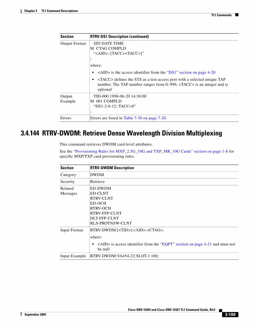
Chapter 3 TL1 Command DescriptionsTL1 Commands
3.4.144 RTRV-DWDM: Retrieve Dense Wavelength Division MultiplexingThis command retrieves DWDM card-level attributes.
See the “Provisioning Rules for MXP_2.5G_10G and TXP_MR_10G Cards” section on page 1-8 for specific MXP/TXP card provisioning rules.
Output Format SID DATE TIMEM CTAG COMPLD “<AID>::[TACC=<TACC>]”;
where:
• <AID> is the access identifier from the “DS1” section on page 4-20
• <TACC> defines the STS as a test access port with a selected unique TAP number. The TAP number ranges from 0–999; <TACC> is an integer and is optional
Output Example
TID-000 1998-06-20 14:30:00M 001 COMPLD “DS1-2-6-12::TACC=8”;
Errors Errors are listed in Table 7-30 on page 7-20.
Section RTRV-DS1 Description (continued)
Section RTRV-DWDM Description
Category DWDM
Security Retrieve
Related Messages
ED-DWDMED-CLNTRTRV-CLNTED-OCHRTRV-OCHRTRV-FFP-CLNTDLT-FFP-CLNTRLS-PROTNSW-CLNT
Input Format RTRV-DWDM:[<TID>]:<AID>:<CTAG>;
where:
• <AID> is access identifier from the “EQPT” section on page 4-21 and must not be null
Input Example RTRV-DWDM:VA454-22:SLOT-1:100;
3-199Cisco ONS 15454 and Cisco ONS 15327 TL1 Command Guide, R4.0
September 2004

Chapter 3 TL1 Command DescriptionsTL1 Commands
Output Format SID DATE TIMEM CTAG COMPLD “<AID>:<AIDTYPE>,<EQUIP>,,[<STATUS>]:[PEERID=<PEERID>,] [TERMMODE=<TERMMODE>,][PAYLOAD=<PAYLOAD>,] [CARDNAME=<CARDNAME>,][PWL=<PWL>,] [TWL1=<TWL1>,][TWL2=<TWL2>,]:[<PST>],[<SST>]”;
where:
• <AID> is the access identifier from the “EQPT” section on page 4-21
• <AIDTYPE> specifies the type of AID; valid values are shown in the “EQPT_TYPE” section on page 4-63 and <AIDTYPE> is a string
• <EQUIP> indicates if the equipment unit is physically present; valid values are shown in the “EQUIP” section on page 4-66
• <STATUS> indicates a status. SONET card status is shown on its card level; valid values are shown in the “STATUS” section on page 4-87 and <STATUS> is optional
• <PEERID> is the regeneration group peer card slot. <PEERID> is the AID from the “EQPT” section on page 4-21 and is optional
• <TERMMODE> is the termination mode of the card; valid values are shown in the “TERM_MODE” section on page 4-93 and <TERMMODE> is optional
• <PAYLOAD> is the type of payload carried; valid values are shown in the “PAYLOAD” section on page 4-83 and <PAYLOAD> is optional
• <CARDNAME> is the name of the card as assigned in the manufacturing information; <CARDNAME> is a string and is optional
• <PWL> provisioned wavelength; valid values are shown in the “OPTICAL_WLEN” section on page 4-81 and <PWL> is optional
• <TWL1> tunable wavelength 1; valid values are shown in the “OPTICAL_WLEN” section on page 4-81 and <TWL1> is optional
• <TWL2> tunable wavelength 1; valid values are shown in the “OPTICAL_WLEN” section on page 4-81 and <TWL2> is optional
• <PST> primary state; valid values are shown in the “PST” section on page 4-85 and <PST> is optional
• <SST> secondary state; valid values are shown in the “SST” section on page 4-87 and <SST> is optional
Output Example
TID-000 1998-06-20 14:30:00M 001 COMPLD “SLOT-1:TRANS-10G,EQUIP,,ACT:PEERID=SLOT-2,TERMMODE=TRANS, PAYLOAD=SONET,CARDNAME=TRUNK-1,PWL=1530.33,TWL1=1530.33, TWL2=1531.12:IS,AINS”;
Errors Errors are listed in Table 7-30 on page 7-20.
Section RTRV-DWDM Description (continued)
3-200Cisco ONS 15454 and Cisco ONS 15327 TL1 Command Guide, R4.0
September 2004

Chapter 3 TL1 Command DescriptionsTL1 Commands
3.4.145 RTRV-EC1: Retrieve EC1(Cisco ONS 15454 only)
This command retrieves the facility status of an EC1 card.
Section RTRV-EC1 Description
Category Ports
Security Retrieve
Related Messages
ED-<OCN_TYPE> RST-<MOD2_IO>ED-DS1 RTRV-<OCN_TYPE>ED-EC1 RTRV-DS1ED-G1000 RTRV-G1000ED-T1 RTRV-T1ED-T3 RTRV-T3RMV-<MOD2_IO>
Input Format RTRV-EC1:[<TID>]:<AID>:<CTAG>[::::];
where:
• <AID> is from the “FACILITY” section on page 4-22 and must not be null
Input Example RTRV-EC1:CISCO:FAC-1-1:1234;
Output Format SID DATE TIMEM CTAG COMPLD “<AID>::[PJMON=<PJMON>,][LBO=<LBO>,][RXEQUAL=<RXEQUAL>,] [SOAK=<SOAK>]:<PST>,[<SST>]”;
where:
• <AID> is the facility AID of an EC1 port and is from the “FACILITY” section on page 4-22
• <PJMON> is the SONET pointer monitor attribute of an EC1 port; <PJMON> is an integer and is optional
• <LBO> is the line build-out value of an EC1 port; valid values for <LBO> are shown in the “E_LBO” section on page 4-62, <LBO> is optional
• Valid values for <RXEQUAL> are shown in the “EXT_RING” section on page 4-68, <RXEQUAL> is optional
• <SOAK> OOS-AINS to IS transition soak time measured in 15 minute intervals; <SOAK> is an integer and is optional
• <PST> primary state; valid values are shown in the “PST” section on page 4-85
• <SST> secondary state; valid values are shown in the “SST” section on page 4-87 and <SST> is optional
Output Example
TID-000 1998-06-20 14:30:00M 001 COMPLD “FAC-1-1::PJMON=0,LBO=0-225,RXEQUAL=Y,SOAK=10:OOS,AINS”;
Errors Errors are listed in Table 7-30 on page 7-20.
3-201Cisco ONS 15454 and Cisco ONS 15327 TL1 Command Guide, R4.0
September 2004

Chapter 3 TL1 Command DescriptionsTL1 Commands
3.4.146 RTRV-EQPT: Retrieve EquipmentThis command retrieves protection group information and status information for all the cards.
This command returns the PRTYPE, PROTID, RVTM, and RVRTV parameters for a card inside of a protection group by the following scenario:
1. A working AID/card within a 1:1 protection group should return PRTYPE, PROTID, RVTM and RVRTV.
2. A protection/AID card within a 1:1 protection group should return PRTYPE, RVTM and RVRTV.
3. A working AID/card within a 1:N protection group should return PRTYPE, PROTID, RVTM and RVRTV=Y.
4. A protection AID/card of a 1:1 protection group should return PRTYPE, RVTM and RVRTV=Y.
5. An unprotected AID/card, the AID type, equip (equip/unequip), status (act/standby) and state (IS/OOS) values.
Error conditions:
1. The equipment is not provisioned.
Section RTRV-EQPT Description
Category Equipment
Security Retrieve
Related Messages
ALW-SWDX-EQPT INH-SWTOWKG-EQPTALW-SWTOPROTN-EQPT REPT ALM EQPTALW-SWTOWKG-EQPT REPT EVT EQPTDLT-EQPT RTRV-ALM-EQPTED-EQPT RTRV-COND-EQPTENT-EQPT SW-DX-EQPTINH-SWDX-EQPT SW-TOPROTN-EQPTINH-SWTOPROTN-EQPT SW-TOWKG-EQPT
Input Format RTRV-EQPT:[<TID>]:<AID>:<CTAG>[::::];
where:
• <AID> is from the “EQPT” section on page 4-21 and must not be null
Input Example RTRV-EQPT:MIRABEL:SLOT-12:230;
3-202Cisco ONS 15454 and Cisco ONS 15327 TL1 Command Guide, R4.0
September 2004

Chapter 3 TL1 Command DescriptionsTL1 Commands
Output Format SID DATE TIMEM CTAG COMPLD “<AID>:<AIDTYPE>,<EQUIP>,[<ROLE>],[<STATUS>]: [PROTID=<PROTID>,][PRTYPE=<PRTYPE>,] [RVRTV=<RVRTV>,][RVTM=<RVTM>,] [CARDNAME=<CARDNAME>,] [IOSCFG=<IOSCFG>]:[<PST>],[<SST>]”;
where:
• <AID> is the equipment unit identifier and is from the“EQPT” section on page 4-21
• <AIDTYPE> is a string
• <EQUIP> indicates if the equipment unit is physically present; valid values are shown in the “EQUIP” section on page 4-66
• <ROLE> indicates if the card is a working unit or a protecting unit; valid values are shown in the “SIDE” section on page 4-87, <ROLE> is optional
• <STATUS> indicates a status. SONET card status is shown on it’s line/port level. Valid values for <STATUS> are shown in the “STATUS” section on page 4-87, <STATUS> is optional
• <PROTID> indicates the protecting identifier; <PROTID> is from the “PRSLOT” section on page 4-16 and is optional
• <PRTYPE> indicates the protection type; valid values are shown in the “PROTECTION_GROUP” section on page 4-84, <PRTYPE> is optional
• <RVRTV> indicates a revertive mode; valid values are shown in the “ON_OFF” section on page 4-79, <RVRTV> is optional
• <RVTM> indicates the revertive time; valid values for <RVTM> are shown in the “REVERTIVE_TIME” section on page 4-85, <RVTM> is optional
• <CARDNAME> is a string and is optional
• <IOSCFG> displays the information about startup IOS config file for the ML1000-2 and ML100T-12 cards. An example of this field is “TL1,11.22.33.44//DIR/IOS.CONF,2002/1/1 9:1:1 EST”. The following information is included in this field: 1) Where the config file is from: TL1, or CTC/CTM/CLI/TCC; 2) The host (IP address)/directory/file name, if the config file is downloaded from the network; 3) When the startup config file is created (by copying from the network, for example). This field only applies to ML1000-2 and ML100T-12 cards. <IOSCFG> is a String. <IOSCFG> is optional.
• <PST> primary state; valid values are shown in the “PST” section on page 4-85, <PST> is optional
• <SST> secondary state; valid values are shown in the “SST” section on page 4-87, <SST> is optional
Section RTRV-EQPT Description (continued)
3-203Cisco ONS 15454 and Cisco ONS 15327 TL1 Command Guide, R4.0
September 2004

Chapter 3 TL1 Command DescriptionsTL1 Commands
3.4.147 RTRV-EXT-CONT: Retrieve External ControlThis command retrieves the control state of an external control. The command can be used to audit the result of an OPR-EXT-CONT or a RLS-EXT-CONT command.
Notes:
1. If the CONTTYPE is null, the existing conttype on this AID will be returned.
2. The duration is not supported, it defaults to CONTS.
Output Example
TID-000 1998-06-20 14:30:00M 001 COMPLD “SLOT-12:DS1,EQUIP,,ACT:PROTID=SLOT-13,PRTYPE=1-1,RVRTV=Y, RVTM=8.5,CARDNAME=DESCRIPTION,IOSCFG= “IOS CONFIG INFO FOR ML SERIES CARD”:OOS,AINS”;
Errors Errors are listed in Table 7-30 on page 7-20.
Section RTRV-EQPT Description (continued)
Section RTRV-EXT-CONT Description
Category Environment Alarms and Controls
Security Retrieve
Related Messages
OPR-ACO-ALL RTRV-ATTR-CONTOPR-EXT-CONT RTRV-ATTR-ENVREPT ALM ENV RTRV-COND-ENVREPT EVT ENV SET-ATTR-CONTRLS-EXT-CONT SET-ATTR-ENVRTRV-ALM-ENV
Input Format RTRV-EXT-CONT:[<TID>]:<AID>:<CTAG>[::<CONTTYPE>];
where:
• <AID> is from the “ENV” section on page 4-20 and must not be null.
Note For this command only ENV-OUT-{1-2} is a valid AID.
• Valid values for <CONTTYPE> are shown in the “CONTTYPE” section on page 4-59. A null value is equivalent to ALL
Input Example RTRV-EXT-CONT:CISCO:ENV-OUT-2:123::AIRCOND;
3-204Cisco ONS 15454 and Cisco ONS 15327 TL1 Command Guide, R4.0
September 2004

Chapter 3 TL1 Command DescriptionsTL1 Commands
3.4.148 RTRV-FFP-<OCN_TYPE>: Retrieve Facility Protection Group (OC3, OC12, OC48, OC192)
See Table 4-11 on page 4-6 for supported modifiers by platform.
This command retrieves the optical facility protection information.
Output Format SID DATE TIMEM CTAG COMPLD “<AID>:[<CONTTYPE>],<DUR>,[<CONTSTATE>]”;
where:
• <AID> identifies the external control for which control state is being retrieved and is from the “ENV” section on page 4-20
• <CONTTYPE> is the type of control for which control state is being retrieved; valid values are shown in the “CONTTYPE” section on page 4-59, <CONTTYPE> is optional
• <DUR> is the duration for which the external control can be operated; valid values are shown in the “DURATION” section on page 4-62
• <CONTSTATE> is the control of the external control; valid values are shown in the “CONT_MODE” section on page 4-59, <CONTSTATE> is optional
Output Example
TID-000 1998-06-20 14:30:00M 001 COMPLD “ENV-OUT-2:AIRCOND,CONTS,OPEN”;
Errors Errors are listed in Table 7-30 on page 7-20.
Section RTRV-EXT-CONT Description (continued)
Section RTRV-FFP-<OCN_TYPE> Description
Category SONET Line Protection
Security Retrieve
Related Messages
DLT-FFP-<OCN_TYPE>ED-FFP-<OCN_TYPE>ENT-FFP-<OCN_TYPE>EX-SW-<OCN_BLSR>OPR-PROTNSW-<OCN_TYPE>RLS-PROTNSW-<OCN_TYPE>RTRV-PROTNSW-<OCN_TYPE>
Input Format RTRV-FFP-<OCN_TYPE>:[<TID>]:<AID>:<CTAG>[::::];
where:
• <AID> is the optical facility AID from the “FACILITY” section on page 4-22 and must not be null
Input Example RTRV-FFP-OC3:PETALUMA:FAC-1-1:1;
3-205Cisco ONS 15454 and Cisco ONS 15327 TL1 Command Guide, R4.0
September 2004

Chapter 3 TL1 Command DescriptionsTL1 Commands
3.4.149 RTRV-FFP-CLNT: Retrieve Facility Protection Group ClientThis command retrieves Y cable protection on client facilities.
See the “Provisioning Rules for MXP_2.5G_10G and TXP_MR_10G Cards” section on page 1-8 for specific MXP/TXP card provisioning rules.
Output Format SID DATE TIMEM CTAG COMPLD “<WORK>,<PROTECT>::[PROTID=<PROTID>,][RVRTV=<RVRTV>,] [RVTM=<RVTM>,][PSDIRN=<PSDIRN>]”;
where:
• <WORK> identifies the working port and is the AID from the “FACILITY” section on page 4-22
• <PROTECT> identifies the protection port and is the AID from the “FACILITY” section on page 4-22
• <PROTID> is a protection group identifier (protection group name). It defaults to the protecting port of the protection group; <PROTID> is a string, it is optional and can have a maximum length of 32 characters
• <RVRTV> identifies a revertive mode and defaults to N (non-revertive mode); valid values are shown in the “ON_OFF” section on page 4-79, <RVRTV> is optional
• <RVTM> identifies the revertive time and defaults to 5.0 minutes; valid values are shown in the “REVERTIVE_TIME” section on page 4-85, <RVTM> is optional
• <PSDIRN> indicates the switch mode and defaults to UNI. valid values are shown in the “UNI_BI” section on page 4-97, <PSDIRN> is optional
Output Example
TID-000 1998-06-20 14:30:00M 001 COMPLD “FAC-2-1,FAC-1-1::PROTID=PROT_NAME,RVRTV=Y, RVTM=1.0,PSDIRN=BI”;
Errors Errors are listed in Table 7-30 on page 7-20.
Section RTRV-FFP-<OCN_TYPE> Description (continued)
Section RTRV-FFP-CLNT Description
Category DWDM
Security Retrieve
Related Messages
ENT-FFP-CLNTED-FFP-CLNTDLT-FFP-CLNTRTRV-CLNTED-CLNTED-DWDMRTRV-DWDM
3-206Cisco ONS 15454 and Cisco ONS 15327 TL1 Command Guide, R4.0
September 2004

Chapter 3 TL1 Command DescriptionsTL1 Commands
Input Format RTRV-FFP-CLNT:[<TID>]:<AID>:<CTAG>[::::];
where:
• <AID> is the access identifier from the “FACILITY” section on page 4-22 and must not be null
Input Example RTRV-FFP-CLNT:CISCO:FAC-1-1:100;
Output Format SID DATE TIMEM CTAG COMPLD “<WORKAID>,<PROTAID>::[PROTTYPE=<PROTTYPE>,] [PROTID=<PROTID>,][RVRTV=<RVRTV>,][RVTM=<RVTM>,] [PSDIRN=<PSDIRN>]”;
where:
• <WORKAID> identifies a working port and is the AID from the “FACILITY” section on page 4-22
• <PROTAID> identifies a protection port and is the AID from the “FACILITY” section on page 4-22
• <PROTTYPE> identifies the type of facility protection; valid values are shown in the “PROTTYPE” section on page 4-84 and <PROTTYPE> is optional
• <PROTID> protection group identifier (protection group name). Defaults to the protecting port AID of the protection group. Is is a string and can have a maximum length of 32 characters; <PROTID> is a string and is optional
• <RVRTV> identifies the revertive mode. Defaults to N (non-revertive mode); valid values are shown in the “ON_OFF” section on page 4-79 and <RVRTV> is optional
• <RVTM> identifies the revertive time. Defaults to 5.0 minutes; valid values are shown in the “REVERTIVE_TIME” section on page 4-85 and <RVTM> is optional
• <PSDIRN> identifies the switching mode and defaults to UNI; valid values are shown in the “UNI_BI” section on page 4-97 and <PSDIRN> is optional
Output Example
TID-000 1998-06-20 14:30:00M 001 COMPLD “FAC-1-1,FAC-2-1::PROTTYPE=Y-CABLE,PROTID=DC-METRO,RVRTV=N, RVTM=1.0,PSDIRN=BI”;
Errors Errors are listed in Table 7-30 on page 7-20.
Section RTRV-FFP-CLNT Description (continued)
3-207Cisco ONS 15454 and Cisco ONS 15327 TL1 Command Guide, R4.0
September 2004

Chapter 3 TL1 Command DescriptionsTL1 Commands
3.4.150 RTRV-FSTE: Retrieve Fast EthernetSee Table 4-11 on page 4-6 for supported modifiers by platform.
This command retrieves the front end port information of the ML100T-12 Ethernet card.
Section RTRV-FSTE Description
Category Ports
Security Retrieve
Related Messages
ED-<OCN_TYPE> RTRV-<OCN_TYPE>ED-DS1 RTRV-DS1ED-EC1 RTRV-EC1ED-G1000 RTRV-G1000ED-T1 RTRV-GIGEED-T3 RTRV-POSINIT-REG-G1000 RTRV-T1RMV-<MOD2_IO> RTRV-T3RST-<MOD2_IO>
Input Format RTRV-FSTE:[<TID>]:<AID>:<CTAG>;
where:
• <AID> is the facility AID from the “FACILITY” section on page 4-22 and must not be null
Input Example RTRV-FSTE:TID:FAC-1-1:CTAG;
Output Format SID DATE TIMEM CTAG COMPLD “<AID>::[ADMINSTATE=<ADMINSTATE>,][LINKSTATE=<LINKSTATE>,] [MTU=<MTU>,][FLOWCTRL=<FLOWCTRL>,][DUPLEX=<DUPLEX>,] [SPEED=<SPEED>]”;
where:
• <AID> is the AID from the “FACILITY” section on page 4-22
• <ADMINSTATE> administration type; valid values are shown in the “UP_DOWN” section on page 4-98. <ADMINSTATE> is optional
• <LINKSTATE> link protocol; valid values are shown in the “UP_DOWN” section on page 4-98. <LINKSTATE> is optional
• <MTU> maximum transport unit; <MTU> is an integer and is optional
• <FLOWCTRL> flow control; valid values are shown in the “FLOW” section on page 4-69. <FLOWCTRL> is optional
• <DUPLEX> duplex mode; valid values are shown in the “ETHER_DUPLEX” section on page 4-67. <DUPLEX> is optional
• <SPEED> Ethernet speed; valid values are shown in the “ETHER_SPEED” section on page 4-68. <SPEED> is optional
3-208Cisco ONS 15454 and Cisco ONS 15327 TL1 Command Guide, R4.0
September 2004

Chapter 3 TL1 Command DescriptionsTL1 Commands
3.4.151 RTRV-G1000: Retrieve G1000 Facility(Cisco ONS 15454 only)
This command retrieves the G1000 facilities configuration.
Output Example
TID-000 1998-06-20 14:30:00M 001 COMPLD “FAC-1-1::ADMINSTATE=DOWN,LINKSTATE=DOWN,MTU=1500, FLOWCTRL=SYMMETRIC,DUPLEX=AUTO,SPEED=AUTO”;
Errors Errors are listed in Table 7-30 on page 7-20.
Section RTRV-FSTE Description (continued)
Section RTRV-G1000 Description
Category Ports
Security Retrieve
Related Messages
ED-<OCN_TYPE> RTRV_<OCN_TYPE>ED-DS1 RTRV-DS1ED-EC1 RTRV-EC1ED-G1000 RTRV-FSTEED-T1 RTRV-GIGEED-T3 RTRV-POSINIT-REG-G1000 RTRV-T1RMV-<MOD2_IO> RTRV-T3RST-<MOD2_IO>
Input Format RTRV-G1000:[<TID>]:<AID>:<CTAG>;
where:
• <AID> is from the “FACILITY” section on page 4-22 and must not be null
Input Example RTRV-G1000:TID:FAC-1-1:CTAG;
3-209Cisco ONS 15454 and Cisco ONS 15327 TL1 Command Guide, R4.0
September 2004

Chapter 3 TL1 Command DescriptionsTL1 Commands
3.4.152 RTRV-GIGE: Retrieve Gigabit EthernetSee Table 4-11 on page 4-6 for supported modifiers by platform.
This command retrieves the front end port information for the ML1000-2 Ethernet card.
Output Format SID DATE TIMEM CTAG COMPLD “<AID>::[MFS=<MFS>,][FLOW=<FLOW>,][LAN=<LAN>,] [OPTICS=<OPTICS>]:<PST>,[<SST>]”;
where:
• <AID> is from the “FACILITY” section on page 4-22
• Valid values for <MFS> are shown in the “MFS_TYPE” section on page 4-71; <MFS> is optional
• Valid values for <FLOW> are shown in the “ON_OFF” section on page 4-79; <FLOW> is optional
• Valid values for <LAN> are shown in the “FLOW” section on page 4-69; <LAN> is optional
• Valid values for <OPTICS> are shown in the “OPTICS” section on page 4-82; <OPTICS> is optional
• <PST> primary state; valid values are shown in the “PST” section on page 4-85
• <SST> secondary state; valid values are shown in the “SST” section on page 4-87; <SST> is optional
Output Example
TID-000 1998-06-20 14:30:00M 001 COMPLD “FAC-1-1::MFS=9032,FLOW=N,LAN=ASYMMETRIC, OPTICS=UNKNOWN:OOS”;
Errors Errors are listed in Table 7-30 on page 7-20.
Section RTRV-G1000 Description (continued)
Section RTRV-GIGE Description
Category Ports
Security Retrieve
Related Messages
ED-<OCN_TYPE> RTRV_<OCN_TYPE>ED-DS1 RTRV-DS1ED-EC1 RTRV-EC1ED-G1000 RTRV-FSTEED-T1 RTRV-G1000ED-T3 RTRV-POSINIT-REG-G1000 RTRV-T1RMV-<MOD2_IO> RTRV-T3RST-<MOD2_IO>
3-210Cisco ONS 15454 and Cisco ONS 15327 TL1 Command Guide, R4.0
September 2004

Chapter 3 TL1 Command DescriptionsTL1 Commands
Input Format RTRV-GIGE:[<TID>]:<AID>:<CTAG>;
where:
• <AID> is from the “FACILITY” section on page 4-22 and must not be null
Input Example RTRV-GIGE:TID:FAC-1-1:CTAG;
Output Format SID DATE TIMEM CTAG COMPLD “<AID>::[ADMINSTATE=<ADMINSTATE>,][LINKSTATE=<LINKSTATE>,] [MTU=<MTU>,][FLOWCTRL=<FLOWCTRL>,][OPTICS=<OPTICS>,] [DUPLEX=<DUPLEX>,][SPEED=<SPEED>]”;
where:
• <AID> is the AID from the “FACILITY” section on page 4-22
• <ADMINSTATE> administration type; valid values are shown in the “UP_DOWN” section on page 4-98. <ADMINSTATE> is optional
• <LINKSTATE> link protocol; valid values are shown in the “UP_DOWN” section on page 4-98. <LINKSTATE> is optional
• <MTU> maximum transport unit; <MTU> is an integer and is optional
• <FLOWCTRL> flow control; valid values are shown in the “FLOW” section on page 4-69. <FLOWCTRL> is optional
• <OPTICS> is the optics type; valid values are shown in “OPTICS” section on page 4-82. <OPTICS> is optional
• <DUPLEX> duplex mode; valid values are shown in the “ETHER_DUPLEX” section on page 4-67. <DUPLEX> is optional
• <SPEED> Ethernet speed; valid values are shown in the “ETHER_SPEED” section on page 4-68. <SPEED> is optional
Output Example
TID-000 1998-06-20 14:30:00M 001 COMPLD “FAC-1-1::ADMINSTATE=DOWN,LINKSTATE=DOWN,MTU=1500, FLOWCTRL=SYMMETRIC,OPTICS=1000_BASE_SX,DUPLEX=AUTO, SPEED=AUTO”;
Errors Errors are listed in Table 7-30 on page 7-20.
Section RTRV-GIGE Description (continued)
3-211Cisco ONS 15454 and Cisco ONS 15327 TL1 Command Guide, R4.0
September 2004

Chapter 3 TL1 Command DescriptionsTL1 Commands
3.4.153 RTRV-HDR: Retrieve Header This command retrieves the header of a TL1 response message. Used by TL1 clients to determine if the link to the NE is still active and if the NE is responding to commands.
3.4.154 RTRV-INV: Retrieve Inventory This command retrieves a listing of the equipment inventory. For each unit in the system, it identifies the unit's firmware numbers and the unit's CLEI code.
Section RTRV-HDR Description
Category System
Security Retrieve
Related Messages
ALW-MSG-ALL REPT EVT FXFRAPPLY RTRV-INVCOPY-RFILE RTRV-MAP-NETWORKED-DAT RTRV-NE-GENED-NE-GEN RTRV-NE-IPMAPED-NE-SYNCN RTRV-NE-SYNCNINH-MSG-ALL RTRV-TODINIT-SYS SET-TOD
Input Format RTRV-HDR:[<TID>]::<CTAG>;
Input Example RTRV-HDR:SONOMA::232;
Section RTRV-INV Description
Category System
Security Retrieve
Related Messages
ALW-MSG-ALL REPT EVT FXFRAPPLY RTRV-HDRCOPY-RFILE RTRV-MAP-NETWORKED-DAT RTRV-NE-GENED-NE-GEN RTRV-NE-IPMAPED-NE-SYNCN RTRV-NE-SYNCNINH-MSG-ALL RTRV-TODINIT-SYS SET-TOD
Input Format RTRV-INV:[<TID>]:<AID>:<CTAG>[::::];
where:
• <AID> is an access identifier from the “EQPT” section on page 4-21 and must not be null
Input Example RTRV-INV:OCCIDENTAL:SLOT-15:301;
3-212Cisco ONS 15454 and Cisco ONS 15327 TL1 Command Guide, R4.0
September 2004

Chapter 3 TL1 Command DescriptionsTL1 Commands
Output Format SID DATE TIMEM CTAG COMPLD “<AID>,<AIDTYPE>::[PN=<PN>,][HWREV=<HWREV>,] [FWREV=<FWREV>,][SN=<SN>,][CLEI=<CLEI>][TWL1=<TWL1>,] [TWL2=<TWL2>,][PLUGINVERNDORID=<PLUGINVERNDORID>,] [PLUGINPN=<PLUGINPN>,][PLUGINHWREV=<PLUGINHWREV>,] [PLUGINFWREV=<PLUGINFWREV>,][PLUGINSN=<PLUGINSN>,] [ILOSSREF=<ILOSSREF>]”;
where:
• <AID> is the access identifier from the “EQPT” section on page 4-21
• <AIDTYPE> specifies the type of AID and is a string
• <PN> is the HW part number; <PN> is a string and is optional
• <HWREV> is the HW Rev; <HWREV> is a string and is optional
• <FWREV> is the firmware Rev; <FWREV> is a string and is optional
• <SN> is the serial number; <SN> is a string and is optional
• <CLEI> is a string and is optional
• <TW1> tunable wavelength 1; valid values are shown in the “OPTICAL_WLEN” section on page 4-81 and <TW1> is optional
• <TW2> tunable wavelength 2; valid values are shown in the “OPTICAL_WLEN” section on page 4-81 and <TW2> is optional
• <PLUGINHWREV> applicable in a future release
• <PLUGINFWREV> applicable in a future release
• <PLUGINSN> applicable in a future release
• <ILOSSREF> applicable in a future release
Output Example
TID-000 1998-06-20 14:30:00M 001 COMPLD “SLOT-15,OC3-IR-4::PN=87-31-00002,HWREV=004K, FWREV=76-99-00009-004A,SN=013510,CLEI=NOCLEI,TWL1=1546.12, TWL2=1546.92,PLUGINVERNDORID=012345,PLUGINPN=ABCDE, PLUGINHWREV=ABCDE,PLUGINFWREV=01-02-03, PLUGINSN=01234,ILOSSREF=1.0”;
Errors Errors are listed in Table 7-30 on page 7-20.
Section RTRV-INV Description (continued)
3-213Cisco ONS 15454 and Cisco ONS 15327 TL1 Command Guide, R4.0
September 2004

Chapter 3 TL1 Command DescriptionsTL1 Commands
3.4.155 RTRV-LOG: Retrieve LogThis command retrieves the alarm log of the NE.
Note The only option reported for LOGNM is ALARM.
Section RTRV-LOG Description
Category Log
Security Superuser
Related Messages
ALW-MSG-DBCHGINH-MSG-DBCHGREPT DBCHG
Input Format RTRV-LOG:[<TID>]::<CTAG>::<LOGNM>;
where:
• <LOGNM> is the log name - ALARM; <LOGNM> is a string and must not be null
Input Example RTRV-LOG:CISCO::123::ALARM;
Output Format SID DATE TIMEM CTAG COMPLD “<AID>,<ALMNUMBER>:CURRENT=<CURRENT>, [PREVIOUS=<PREVIOUS>,]<CONDITION>,<SRVEFF>,[TIME=<OCRTIME>,] [DATE=<OCRDAT>]:<ALMDESCR>”;
where:
• <AID> is an access identifier from the “ALL” section on page 4-10
• <ALMNUMBER> is an alarm number of the log and is an integer
• <CURRENT> is a current severity; valid values are shown in the “NOTIF_CODE” section on page 4-78
• <PREVIOUS> is a previous severity; valid values are shown in the “COND_EFF” section on page 4-47, <PREVIOUS> is optional
• <CONDITION> is a condition; valid values are shown in the “CONDITION” section on page 4-47
• <SRVEFF> is a service effect; valid values are shown in the “SERV_EFF” section on page 4-86
• <OCRTIME> is the time an alarm is triggered and is optional
• <OCRDAT> is the date an alarm is triggered and is optional
• <ALMDESCR> is the alarm description and is a string
Output Example
TID-000 1998-06-20 14:30:00M 001 COMPLD “FAC-3-1,18:CURRENT=MJ,PREVIOUS=CL,EOC,NSA, TIME=16-33-04,DATE=1971-02-03:\“SDCC TERMINATION FAILURE\””;
Errors Errors are listed in Table 7-30 on page 7-20.
3-214Cisco ONS 15454 and Cisco ONS 15327 TL1 Command Guide, R4.0
September 2004

Chapter 3 TL1 Command DescriptionsTL1 Commands
3.4.156 RTRV-MAP-NETWORK: Retrieve Map NetworkThis command retrieves all the NE attributes which are reachable from the GNE (gateway NE). The NE attributes include the node IP address (IPADDR), node name (TID), and the product type of the NE (PRODUCT).
Note The product type field in the response will be displayed as “unknown” for nodes that are not running the 4.0 version software.
3.4.157 RTRV-NE-GEN: Retrieve Network Element GeneralThis command retrieves the general NE attributes.
The ETHIPADDR/ETHIPMASK are used to show the Ethernet interface address and mask. Both default to the node’s IP address and mask.
Section RTRV-MAP-NETWORK Description
Category Network
Security Retrieve
Related Messages
RTRV-NE-IPMAP
Input Format RTRV-MAP-NETWORK:[<TID>]::<CTAG>;
Input Example RTRV-MAP-NETWORK:CISCO::123;
Output Format SID DATE TIMEM CTAG COMPLD “<IPADDR>,<NODENAME>,<PRODUCT>” ;
where:
• <IPADDR> indicates the node IP address and is a string
• <NODENAME> indicates the node name (TID) and is a string
• <PRODUCT> indicates the product type of the NE; valid values are shown in the “PRODUCT_TYPE” section on page 4-84
Output Example
TID-000 1998-06-20 14:30:00M 001 COMPLD “172.20.222.225,TID-000,15454”;
Errors Errors are listed in Table 7-30 on page 7-20.
Section RTRV-NE-GEN Description
Category System
Security Retrieve
3-215Cisco ONS 15454 and Cisco ONS 15327 TL1 Command Guide, R4.0
September 2004

Chapter 3 TL1 Command DescriptionsTL1 Commands
Related Messages
ALW-MSG-ALL REPT EVT FXFRAPPLY RTRV-HDRCOPY-RFILE RTRV-INVED-DAT RTRV-MAP-NETWORKED-NE-GEN RTRV-NE-IPMAPED-NE-SYNCN RTRV-NE-SYNCNINH-MSG-ALL RTRV-TODINIT-SYS SET-TOD
Input Format RTRV-NE-GEN:[<TID>]::<CTAG>;
Input Example RTRV-NE-GEN:CISCO::123;
Output Format SID DATE TIMEM CTAG COMPLD “[IPADDR=<IPADDR>,][IPMASK=<IPMASK>,][DEFRTR=<DEFRTR>,] [IIOPPORT=<IIOPPORT>,][NTP=<NTP>,][ETHIPADDR=<ETHIPADDR>,] [ETHIPMASK=<ETHIPMASK>,][NAME=<NAME>,][SWVER=<SWVER>,] [LOAD=<LOAD>,][PROTSWVER=<PROTSWVER>,] [PROTLOAD=<PROTLOAD>,][DEFDESC=<DEFDESC>] [PLATFORM=<PLATFORM>]”;
where:
• <IPADDR> indicates the node IP address; <IPADDR> is a string and is optional
• <IPMASK> indicates the node IP mask; <IPMASK> is a string and is optional
• <DEFRTR> indicates the node default router; <DEFRTR> is a string and is optional
• <IIOPPORT> indicates the node IIOP port; <IIOPPORT> is an integer and is optional
• <NTP> indicates the node’s NTP timing source address; <NTP> is a string and is optional
• <ETHIPADDR> indicates the node’s Ethernet IP address; <ETHIPADDR> is a string and is optional
• <ETHIPMASK> indicates the node’s Ethernet IP mask; <ETHIPMASK> is a string and is optional
• <NAME> is the node name; <NAME> is a string and is optional
• <SWVER> is the software version; <SWVER> is a string and is optional
• <LOAD> is a string and is optional
• <PROTSWVER> is protect software version; <PROTSWVER> is a string and is optional
• <PROTLOAD> is a string and is optional
• <DEFDESC> is a string and is optional
• <PLATFORM> is the NE platform type; <PLATFORM> is a string and is optional
Section RTRV-NE-GEN Description (continued)
3-216Cisco ONS 15454 and Cisco ONS 15327 TL1 Command Guide, R4.0
September 2004

Chapter 3 TL1 Command DescriptionsTL1 Commands
3.4.158 RTRV-NE-IPMAP: Retrieve Network Element IPMAPThis command retrieves the IP address and node name of the NEs that have the DCC connection with this NE.
Note This command only reports the active DCC link. If there is no active DCC link on the port (or the node), the command will return COMPLD without IPMAP information.
Output Example
TID-000 1998-06-20 14:30:00M 001 COMPLD “IPADDR=192.168.100.52,IPMASK=255.255.255.0,DEFRTR=192.168.100.1, IIOPPORT=57970,NTP=192.168.100.52,ETHIPADDR=172.20.208.225, ETHIPMASK=255.255.255.0,NAME=“NODENAME”,SWVER=2.01.03, LOAD=02.13-E09A-08.15,PROTSWVER=2.01.02, PROTLOAD=02.12-E09A-09.25,DEFDESC=\“NE DEFAULTS FEATURE\”, PLATFORM=15454-ANSI”
;
Errors Errors are listed in Table 7-30 on page 7-20.
Section RTRV-NE-GEN Description (continued)
Section RTRV-NE-IPMAP Description
Category Network
Security Retrieve
Related Messages
ALW-MSG-ALL RTRV-INVED-DAT RTRV-MAP-NEWORKED-NE-GEN RTRV-NE-GENED-NE-SYNCN RTRV-NE-SYNCNINH-MSG-ALL RTRV-TODINIT-SYS SET-TODRTRV-HDR
Input Format RTRV-NE-IPMAP:[<TID>]:[<AID>]:<CTAG>;
where:
• <AID> is the port of an NE carrying the DCC connection; <AID> is from the “FACILITY” section on page 4-22 and a null value is equivalent to ALL
Input Example RTRV-NE-IPMAP:CISCO:FAC-12-1:123;
3-217Cisco ONS 15454 and Cisco ONS 15327 TL1 Command Guide, R4.0
September 2004

Chapter 3 TL1 Command DescriptionsTL1 Commands
3.4.159 RTRV-NE-SYNCN: Retrieve Network Element SynchronizationThis command retrieves the synchronization attributes of the NE.
Notes:
1. Although mixed mode timing is supported in this release, it is not recommended. See the “Mixed Mode Timing Support” section on page 1-14 for more information.
2. The existing external and line modes have the same functionality in all 3.x releases:
– External mode: the node derives its timing from the BITS inputs.
– Line mode: the node derives its timing from the SONET line(s).
– Mixed mode: the node derives its timing from the BITS input or SONET lines.
Output Format SID DATE TIMEM CTAG COMPLD “<AID>:<IPADDR>,<NODENAME>”;
where:
• <AID> is the port of an NE carrying a DCC connection and is from the “FACILITY” section on page 4-22
• <IPADDR> indicates the NE IP address and is a string
• <NODENAME> indicates the NE node name and is a string
Output Example
TID-000 1998-06-20 14:30:00M 001 COMPLD “FAC-12-1:172.20.208.225,NODENAME2”
;
Errors Errors are listed in Table 7-30 on page 7-20.
Section RTRV-NE-IPMAP Description (continued)
Section RTRV-NE-SYNCN Description
Category Synchronization
Security Retrieve
3-218Cisco ONS 15454 and Cisco ONS 15327 TL1 Command Guide, R4.0
September 2004

Chapter 3 TL1 Command DescriptionsTL1 Commands
Related Messages
ALW-MSG-ALL REPT EVT SYNCNAPPLY RLS-SYNCNSWCOPY-RFILE RTRV-ALM-BITSED-BITS RTRV-ALM-SYNCNED-DAT RTRV-BITSED-NE-GEN RTRV-COND-BITSED-NE-SYNCN RTRV-COND-SYNCNED-SYNCN RTRV-HDRINH-MSG-ALL RTRV-INVINIT-SYS RTRV-MAP-NETWORKOPR-SYNCNSW RTRV-NE-GENREPT ALM BITS RTRV-NE IPMAPREPT ALM SYNCN RTRV-SYNCNREPT EVT BITS RTRV-TODREPT EVT FXFR SET-TOD
Input Format RTRV-NE-SYNCN:[<TID>]::<CTAG>[::::];
Input Example RTRV-NE-SYNCN:CISCO::123;
Output Format SID DATE TIMEM CTAG COMPLD “::[TMMD=<TMMD>,][SSMGEN=<SSMGEN>,][QRES=<QRES>,] [RVRTV=<RVRTV>,][RVTM=<RVTM>]”;
where:
• <TMMD> is a timing mode; valid values are shown in the “TIMING_MODE” section on page 4-93, <TMMD> is optional
• <SSMGEN> is an SSM generator; valid values are shown in the “SYNC_GENERATION” section on page 4-90, <SSMGEN> is optional
• <QRES> is a quality of RES; valid values are shown in the “SYNC_QUALITY_LEVEL” section on page 4-90, <QRES> is optional
• <RVRTV> is a revertive mode; valid values are shown in the “ON_OFF” section on page 4-79, <RVRTV> is optional
• <RVTM> is a revertive time; valid values are shown in the “REVERTIVE_TIME” section on page 4-85, <RVTM> is optional
Output Example
TID-000 1998-06-20 14:30:00M 001 COMPLD “::TMMD=LINE,SSMGEN=GEN1,QRES=ABOVE-PRS,RVRTV=Y,RVTM=8.0”
;
Errors Errors are listed in Table 7-30 on page 7-20.
Section RTRV-NE-SYNCN Description (continued)
3-219Cisco ONS 15454 and Cisco ONS 15327 TL1 Command Guide, R4.0
September 2004

Chapter 3 TL1 Command DescriptionsTL1 Commands
3.4.160 RTRV-OCH: Retrieve Optical Channel(Cisco ONS 15454 only)
This command retrieves the attributes (service parameters) and state of an OCH facility.
See the “Provisioning Rules for MXP_2.5G_10G and TXP_MR_10G Cards” section on page 1-8 for specific MXP/TXP card provisioning rules.
Section RTRV-OCH Description
Category DWDM
Security Retrieve
Related Messages
ED-OCHED-DWDMRTRV-DWDMRTRV-ALM-OCHRTRV-COND-OCH
Input Format RTRV-OCH:[<TID>]:<AID>:<CTAG>;
where:
• <AID> is an access identifier from the “CHANNEL” section on page 4-19 and must not be null
Input Example RTRV-OCH:PENNGROVE:CHAN-6-2:236;
Output Format SID DATE TIMEM CTAG COMPLD “<AID>:,,,[<STATUS>],[<RDIRN>],[<OPTICALPORTTYPE>],[<POWER>], [<EXPWLEN>],[<ACTWLEN>]:[ILOSS=<ILOSS>,] [VOAMODE=<VOAMODE>,][VOAATTN=<VOAATTN>,] [VOAPWR=<VOAPWR>,][VOAREFATTN=<VOAREFATTN>,] [VOAREFPWR=<VOAREFPWR>,][REFOPWR=<REFOPWR>,] [CALOPWR=<CALOPWR>,][SFBER=<SFBER>,][SDBER=<SDBER>,] [ALSMODE=<ALSMODE>,][ALSRCINT=<ALSRCINT>,] [ALSRCPW=<ALSRCPW>,][COMM=<COMM>,][GCCRATE=<GCCRATE>,] [DWRAP=<DWRAP>,][FEC=<FEC>,][OSFBER=<OSFBER>,] [OSDBER=<OSDBER>,][MACADDR=<MACADDR>,] [SYNCMSG=<SYNCMSG>,][SENDDUS=<SENDDUS>,] [LSRSTAT=<LSRSTAT>,][SOAK=<SOAK>]:<PST>,[<SST>]”;
3-220Cisco ONS 15454 and Cisco ONS 15327 TL1 Command Guide, R4.0
September 2004

Chapter 3 TL1 Command DescriptionsTL1 Commands
Output Format (continued)
where:
• <AID> is an access identifier and is from the “CHANNEL” section on page 4-19
• Valid values for <STATUS> are shown in the “STATUS” section on page 4-87 and <STATUS> is optional
• <RDIRN> applicable in a future release
• <OPTICALPORTTYPE> applicable in a future release
• <POWER> applicable in a future release
• <EXPWLEN> applicable in a future release
• <ACTWLEN> applicable in a future release
• <ILOSS> applicable in a future release
• <VOAMODE> applicable in a future release
• <VOAATTN> identifies the transmit power attenuation for the variable optical attenuation (VOA). It is expressed in Dbm. The range for MXP/TXP cards is -24.0–=2.0 Dbm. <VOAATTN> is a string and is optional
• <VOAPWR> applicable in a future release
• <VOAREFATTN> applicable in a future release
• <VOAREFPWR> applicable in a future release
• <REFOPWR> applicable in a future release
• <CALOPWR> applicable in a future release
• <SFBER> identifies the SFBER for the SONET payload; valid values are shown in the “SF_BER” section on page 4-86
• <SDBER> identifies the SDBER for the SONET payload; valid values are shown in the “SD_BER” section on page 4-85
• <ALSMODE> indicates if the Automatic Laser Shutdown is enabled or disabled; valid values are shown in the “ALS_MODE” section on page 4-41 and <ALSMODE> is optional
• <ALSRCINT> indicates the ALS recovery interval. Range is 20–300 seconds; <ALSRCINT> is an integer and is optional
• <ALSRCPW> indicates the ALS recovery pulse width. The range is 2–100 seconds, in increments of 100ms, e.g. 30.1; <ALSRCPW> is a float and is optional
• <COMM> indicates if the GCC or DCC is enabled or disabled. The GCC can be enabled only if the digital wrapper has been enabled for the card. The default is NONE. Valid values are shown in the “COMM_TYPE” section on page 4-46. Rules for a MXP/TXP Client port are; only the DCC can be provisioned, if the termination mode is not transparent and the payload is SONET. On a MXP/TXP DWDM port, the DCC can be enabled only if the G.709 is not enabled and if the payload is SONET and the termination mode is not transparent. On a MXP/TXP DWDM port, the GCC can be enabled if there is no DCC and the G.709 flag is enabled. <COMM> is optional
Section RTRV-OCH Description (continued)
3-221Cisco ONS 15454 and Cisco ONS 15327 TL1 Command Guide, R4.0
September 2004

Chapter 3 TL1 Command DescriptionsTL1 Commands
Output Format (continued)
• <GCCRATE> indicates the data rate of the GCC traffic. Valid values are shown in the “GCCRATE” section on page 4-69. The default is 192Kbps. For MXP/TXP cards this applies only to the DWDM port. The 576K option is not supported for this release. <GCCRATE> is optional
• <DWRAP> is the G.709 digital wrapper. It is either on or off. The system default is ON. For MXP/TXP, this applies only to the DWDM port. To enable G.709 there should be no GCC on the DWDM port. To disable G.709 there should be no GCC on the DWDM port. The FEC should be turned to off; valid values are shown in the “ON_OFF” section on page 4-79 and <DWRAP> is optional
• <FEC> is the Forward Error Correction. It can be enabled only if the G.709 is turned ON. It is either on or off. The system default is ON. For MXP/TXP this applies only to the DWDM port. The FEC level PM and thresholds apply if the FEC is turned on; valid values are shown in the “ON_OFF” section on page 4-79 and <FEC> is optional
• <OSFBER> identifies the SFBER for the OTN level. Applicable only if the G.709 is enabled; valid values are shown in the “SF_BER” section on page 4-86 and <OSFBER> is optional
• <OSDBER> identifies the SDBER for the OTN level. Applicable only if the G.709 is enabled; valid values are shown in the “SD_BER” section on page 4-85 and <OSDBER> is optional
• <MACADDR> identifies the MAC address for the 10GE payload; <MACADDR> is a string
• <SYNCMSG> indicates that the facility be enabled to provide the synchronization clock. This does not apply to a TXP card. This applies to an MXP card, only if the payload is SONET/SDH and the card termination mode is as follows: TRANSPARENT - All Client ports are available for all timing selections. All Trunk ports are not available. LINE - All ports are available for all-timing selections.
• <SENDDUS> indicates that the facility send out a Do not Use for Sync message. This does not apply to a TXP card. This applies to a MXP card, only if the payload is SONET/SDH and the card termination mode is as follows: TRANSPARENT - All Client ports are available for all timing selections. All Trunk ports are not available.LINE - All ports are available for all-timing selections. Valid values are shown in the “ON_OFF” section on page 4-79 and <SENDDUS> is optional
• <LSRSTAT> indicates the laser status. If the laser has been shut down it shows DOWN. If it has not been shut down it shows UP. Valid values are shown in the “UP_DOWN” section on page 4-98 and <LSRSTAT> is optional
• <SOAK> OOS-AINS to IS transition soak time as measured in 15–minute intervals. A value of 4 translates to a soak time of one hour. The allowable range is 0–480 intervals. <SOAK> is an integer and is optional
• <PST> primary state; valid values are shown in the “PST” section on page 4-85
• <SST> secondary state; valid values are shown in the “SST” section on page 4-87
Section RTRV-OCH Description (continued)
3-222Cisco ONS 15454 and Cisco ONS 15327 TL1 Command Guide, R4.0
September 2004

Chapter 3 TL1 Command DescriptionsTL1 Commands
3.4.161 RTRV-PM-<MOD2>: Retrieve Performance (CLNT, DS1, EC1, OC3, OC12, OC48, OC192, OCH, STS1, STS3C, STS6C, STS9C, STS12C, STS24C, STS48C, STS192C, T1, T3, VT1)
See Table 4-11 on page 4-6 for supported modifiers by platform.
This command retrieves the values of PM parameters for a specified card type.
<MONTYPE>, <MONLEV>, <MONDAT> and <MONTM> are supported in this release.
<MONLEV> is in the format of LEV-DIRN. Valid values for <DIRN> are shown in the “DIRN” section on page 4-61.
The format of <MONDAT> is MM-DD, where MM (month of the year) ranges from 1–12 and DD (day of the month) ranges from 1–31.
The format for <MONTM> is HH-MM, where HH (hour of the day) ranges from 0–23 and MM (minute of the hour) ranges from 0–59.
Notes:
1. If the <TMPER> is 1-DAY, <MONTM> is not applicable (null), and is treated as null if <MONTM> is not null.
2. A null value for <MONLEV> defaults to 1-UP.
3. A null value for <MONDAT> defaults to the current date (MM-DD).
4. A null value for <MONTM> defaults to the current time (HH-MM).
5. Unless otherwise stated, DS1 cards are the only cards that support the BTH, RCV, and TRMT directions. All other cards only support the RCV direction.
6. After the BLSR switching, the working path is switched out, the traffic goes through the protection path, and the IPPM can be retrieved from the protection STS path.
7. If there is a STS PCA on the protection path, during the BLSR switching, the PCA path is pre-emptive; sending this command on the protection path after BLSR switch, the command returns the PMs off the protection path, not from the PCA path.
8. Retrieve the PM data for the OCH facility.
The rules are as follows: Client port only–Laser and SONET PM’s are applicable and will be displayed. If the card payload is in SONET mode, then SONET PM’s will be displayed, provided the MONLEV criteria is met.
Output Example
TID-000 1998-06-20 14:30:00M 001 COMPLD “CHAN-6-1:,,,ACT,W_E,DROP,10.0,1530.33,1530.33:ILOSS=1.0, VOAMODE=ATTN,VOAATTN=0.5,VOAPWR=0.0,VOAREFATTN=3.5, VOAREFPWR=5.0,REFOPWR=10.5,CALOPWR=0,SFBER=1E-4, SDBER=1E-5,ALSMODE=Y,ALSRCINT=30,ALSRCPW=40.1, COMM=GCC,GCCRATE=192K,DWRAP=Y,FEC=Y,OSFBER=1E-5, OSDBER=1E-4,MACADDR=00-0E-AA-BB-CC-FF,SYNCMSG=Y, SENDDUS=Y,LSRSTAT=UP,SOAK=10:OOS,AINS”;
Errors Errors are listed in Table 7-30 on page 7-20.
Section RTRV-OCH Description (continued)
3-223Cisco ONS 15454 and Cisco ONS 15327 TL1 Command Guide, R4.0
September 2004

Chapter 3 TL1 Command DescriptionsTL1 Commands
Trunk port Laser PM’s are always available. Laser PM’s are only for Near End. If G.709 is enabled, then the OTN PM’s will be displayed. If G.709 is enabled and FEC is enabled, then the FEC PM’s will be displayed. If the card payload is in SONET mode, then SONET PM’s will be displayed. All PM MONVALUES should pass the MONLEV filter criteria.
Section RTRV-PM-<MOD2> Description
Category Performance
Security Retrieve
Related Messages
ALW-PMREPT-ALL RTRV-PMSCHED-ALLINH-PMREPT-ALL RTRV-TH-<MOD2>INIT-REG-<MOD2> SCHED-PMREPT-<MOD2>REPT PM <MOD2> SET-PMMODE-<STS_PATH>RTRV-PMMODE-<STS_PATH> SET-TH-<MOD2>RTRV-PMSCHED-<MOD2>
Input Format RTRV-PM-<MOD2>:[<TID>]:<AID>:<CTAG>::[<MONTYPE>],[<MONLEV>],[<LOCN>],[<DIRN>],[<TMPER>],[<DATE>],[<TIME>];
where:
• <AID> is the access identifier. All the STS, VT1, FACILITY and DS1 AIDs are supported; <AID> is from the “ALL” section on page 4-10 and must not be null
• <MONTYPE> indicates the type of the monitored parameter; valid values are shown in the “ALL_MONTYPE” section on page 4-33. A null value is equivalent to ALL
• <MONLEV> specifies the discriminating level for the requested monitored parameter. <MONLEV> is in the format of LEVEL-DIRN where LEVEL is the measured value of the monitored parameter (MONVAL) and valid values for DIRN are shown in the “DIRN” section on page 4-61. A null value for <MONLEV> defaults to 1-UP. <MONLEV> is a string
• <LOCN> indicates the location; valid values are shown in the “LOCATION” section on page 4-71. A null value defaults to NEND
• <DIRN> is the direction of PM relative to the entity identified by the AID. <DIRN> defaults to ALL, which means that the command initializes all the registers irrespective of the PM direction. Valid values for <DIRN> are shown in the “DIRECTION” section on page 4-60.
• <TMPER> indicates the accumulation time period for the PM information. If the <TMPER> is 1-DAY, <MONTM> is not applicable (null), and is treated as null if <MONTM> is not null. Valid values for <TMPER> are shown in the “TMPER” section on page 4-93. A null value defaults to 15-MIN
• <DATE> is the beginning date of the PM or storage register period specified in <TMPER>. The format of <MONDAT> is MM-DD, where MM (month of year> ranges from 1–12 and DD (day of month) ranges from 1–31. A null value for <MONDAT> defaults to the current date
• <TIME> is the beginning time of day of the PM or storage register period specified in <TMPER>. The format for <MONTM> is HH-MM, where HH (hour of day) ranges from 0–23 and MM (minute of hour) ranges from 0–59. A null value for <MONTM> defaults to the current time (HH-MM)
Input Example RTRV-PM-T1:TID:FAC-2-1:123::CVL,10-UP,NEND,BTH,15-MIN,04-11,12-45;
3-224Cisco ONS 15454 and Cisco ONS 15327 TL1 Command Guide, R4.0
September 2004

Chapter 3 TL1 Command DescriptionsTL1 Commands
Output Format SID DATE TIMEM CTAG COMPLD “<AID>,[<AIDTYPE>]:<MONTYPE>,<MONVAL>,[<VLDTY>], [<LOCN>],[<DIRN>],[<TMPER>],[<MONDAT>],[<MONTM>]”;
where:
• <AID> is an access identifier from the “ALL” section on page 4-10
• <AIDTYPE> specifies the type of AID; valid values are shown in the “MOD2B” section on page 4-74, <AIDTYPE> is optional
• <MONTYPE> indicates the type of monitored parameter; valid values are shown in the “ALL_MONTYPE” section on page 4-33
• <MONVAL> is the measured value of the monitored parameter and is a string
• <VLDTY> is the validity indicator of historical monitoring information; valid values are shown in the “VALIDITY” section on page 4-98, <VLDTY> is optional
• <LOCN> indicates the location; valid values are shown in the “LOCATION” section on page 4-71, <LOCN> is optional
• <DIRN> is the direction of PM relative to the entity identified by the AID; valid values are shown in the “DIRECTION” section on page 4-60, <DIRN> is optional
• <TMPER> indicates the accumulation time period for the PM information; valid values are shown in the “TMPER” section on page 4-93, <TMPER> is optional
• <MONDAT> is the beginning date of the PM or storage register period specified in <TMPER>. The format of <MONDAT> is MM-DD, where MM (month of year> ranges from 1–12 and DD (day of month) ranges from 1–31. <MONDAT> is a string and is optional
• <MONTM> is the beginning time of the day of the PM or storage register period specified in <TMPER>. The format for <MONTM> is HH-MM, where HH (hour of day) ranges from 0– 23 and MM (minute of hour) ranges from 0–59. <MONTM> is a string and is optional.
Output Example
TID-000 1998-06-20 14:30:00M 001 COMPLD “FAC-2-1,DS1-14:CVL,21,COMPL,NEND,BTN,15-MIN,04-11,12-45”;
Errors Errors are listed in Table 7-30 on page 7-20.
Section RTRV-PM-<MOD2> Description (continued)
3-225Cisco ONS 15454 and Cisco ONS 15327 TL1 Command Guide, R4.0
September 2004

Chapter 3 TL1 Command DescriptionsTL1 Commands
3.4.162 RTRV-PMMODE-<STS_PATH>: Retrieve Performance Mode of PM Data Collection (STS1, STS3C, STS6C, STS9C, STS12C, STS24C, STS48C, STS192C)
See Table 4-11 on page 4-6 for supported modifiers by platform.
This command retrieves the type of PM mode that has been previously set in the NE. This command can be used to identify whether the PM parameters are Section, Line or Path type, and to identify whether or not the PM are being collected by the NE.
This command returns the categories that are enabled only.
The PM mode and state of an entity is set by using the SET-PMMODE command.
Notes:
1. This near end monitoring of the intermediate-path PM (IPPM) only supports OC-3, OC-12, OC-48, OC-48AS, OC-192, and EC-1 on STS Path.
2. The far end PM data collection is not supported by the current ONS 15454 in this release.
3. This release of software will support only the Path (P) mode type PM parameters with this command, that is, this command will not be applicable for Line (L) and Section (S) mode types. It should be noted that the PM monitoring for Line (L) and Section (S) are supported by the ONS 15454, and the storing PM data is always performed.
4. This command only returns the categories that are enabled (pmstate is ON), and does not return the categories that are disabled (pmstate is OFF).
Section RTRV-PMMODE-<STS_PATH> Description
Category Performance
Security Retrieve
Related Messages
ALW-PMREPT-ALL RTRV-PMSCHED-ALLINH-PMREPT-ALL RTRV-TH-<MOD2>INIT-REG-<MOD2> SCHED-PMREPT-<MOD2>REPT PM <MOD2> SET-PMMODE-<STS_PATH>RTRV-PM-<MOD2> SET-TH-<MOD2>RTRV-PMSCHED-<MOD2>
Input Format RTRV-PMMODE-<STS_PATH>:[<TID>]:<AID>:<CTAG>::<LOCN>;
where:
• <AID> identifies the entity from where the PM mode is being retrieved; <AID> is from the “STS” section on page 4-24 and must not be null
• <LOCN> identifies the location from where the PM mode is being retrieved; valid values are shown in the “LOCATION” section on page 4-71. <LOCN> must not be null
Input Example RTRV-PMMODE-STS1:CISCO:STS-4-2:123::NEND;
3-226Cisco ONS 15454 and Cisco ONS 15327 TL1 Command Guide, R4.0
September 2004

Chapter 3 TL1 Command DescriptionsTL1 Commands
3.4.163 RTRV-PMSCHED-<MOD2>:Retrieve Performance Monitoring Schedule (CLNT, DS1, EC1, OC3, OC12, OC48, OC192, OCH, STS1, STS3C, STS6C, STS9C, STS12C, STS24C, STS48C, STS192C, T1, T3, VT1)
See Table 4-11 on page 4-6 for supported modifiers by platform.
This command retrieves the PM reporting schedule that was set for the NE by the SCHED-PMREPT command.
Output Format SID DATE TIMEM CTAG COMPLD “<AID>:[<LOCN>],<MODETYPE>”;
where:
• <AID> identifies the entity from where the PM mode is being retrieved; <AID> is from the “STS” section on page 4-24
• <LOCN> identifies the location from where the PM mode is being retrieved; valid values are shown in the “LOCATION” section on page 4-71. <LOCN> is optional.
• <MODETYPE> identifies whether or not the PM mode type is turned on or off; valid values are shown in the “PM_MODE” section on page 4-83
Output Example
TID-000 1998-06-20 14:30:00M 001 COMPLD “STS-4-2:NEND,P”;
Errors Errors are listed in Table 7-30 on page 7-20.
Section RTRV-PMMODE-<STS_PATH> Description (continued)
Section RTRV-PMSCHED-<MOD2> Description
Category Performance
Security Retrieve
Related Messages
ALW-PMREPT-ALL RTRV-PMSCHED-ALLINH-PMREP-ALL RTRV-TH-<MOD2>INIT-REG-<MOD2> SCHED-PMREPT-<MOD2>REPT PM <MOD2> SET-PMMODE-<STS-PATH>RTRV-PM-<MOD2> SET-TH-<MOD2>RTRV-PMMODE-<STS_PATH>
Input Format RTRV-PMSCHED-<MOD2>:[<TID>]:<AID>:<CTAG>;
where:
• <AID> is an access identifier from the “ALL” section on page 4-10; <AID> must not be null
Input Example RTRV-PMSCHED-OC3:CISCO-NODE:FAC-3-1:123;
3-227Cisco ONS 15454 and Cisco ONS 15327 TL1 Command Guide, R4.0
September 2004

Chapter 3 TL1 Command DescriptionsTL1 Commands
3.4.164 RTRV-PMSCHED-ALL: Retrieve Performance Schedule AllThis command retrieves all the PM reporting schedules that were set for the NE by the SCHED-PMREPT command.
Output Format SID DATE TIMEM CTAG COMPLD “<AID>,[<AIDTYPE>]:<REPTINVL>,<REPTDAT>,<REPTTM>, [<NUMINVL>],,[<MONLEV>],<LOCN>,,[<TMPER>],[<TMOFST>], [<INHMODE>]”;
where:
• <AID> access identifier from the “ALL” section on page 4-10
• <AIDTYPE> type of access identifier; valid values are shown in the “MOD2” section on page 4-72. <AIDTYPE> is optional
• <REPTINVL> interval between PM reports; <REPTINVL> is a string
• <REPTDAT> date for the next report; <REPTDAT> is a string
• <REPTTM> the time of day for the next PM report; <REPTTM> is a string
• <NUMINVL> remaining number of intervals over which PM is being reported; <NUMINVL> is and integer and is optional
• <MONLEV> discriminating level for the requested monitored parameter; <MONLEV> is a string and is optional
• <LOCN> location being performance-monitored and refers to the entity identified by the AID; valid values are shown in the “LOCATION” section on page 4-71
• <TMPER> accumulation time period for the PM information; valid values are shown in the “TMPER” section on page 4-93 and <TMPER> is optional
• <TMOFST> is the time offset from the end of the last complete accumulation time period to the beginning of the accumulation period specified by TMPER parameter. <TMOFST> is a string and is optional
• <INHMODE> describes whether the reporting of PM data is inhibited (via the INH-PMREPT-ALL command) or is allowed (via the ALW-PMREPT-ALL command); valid values are shown in the “INH_MODE” section on page 4-70
Output Example
TID-000 1998-06-20 14:30:00M 001 COMPLD “FAC-3-1,OC3:30-MIN,5-25,14-46,100,,1-UP,NEND,,15-MIN,0-0-15,ALW”;
Errors Errors are listed in Table 7-30 on page 7-20.
Section RTRV-PMSCHED-<MOD2> Description (continued)
Section RTRV-PMSCHED-ALL Description
Category Performance
Security Retrieve
3-228Cisco ONS 15454 and Cisco ONS 15327 TL1 Command Guide, R4.0
September 2004

Chapter 3 TL1 Command DescriptionsTL1 Commands
Related Messages
ALW-PMREPT-ALL RTRV-PMSCHED-<MOD2>INH-PMREPT-ALL RTRV-TH-<MOD2>INIT-REG-<MOD2> SCHED-PMREPT-<MOD2>REPT PM <MOD2> SET-PMMODE-<STS_PATHRTRV-PM-<MOD2> SET-TH-<MOD2>RTRV-PMMODE-<STS_PATH>
Input Format RTRV-PMSCHED-ALL:[<TID>]::<CTAG>;
Input Example RTRV-PMSCHED-ALL:CISCO-NODE::123;
Output Format SID DATE TIMEM CTAG COMPLD “<AID>,[<AIDTYPE>]:<REPTINVL>,<REPTDAT>,<REPTTM>, [<NUMINVL>],,[<MONLEV>],<LOCN>,,[<TMPER>],<TMOFST>, [<INHMODE>]”;
where:
• <AID> access identifier from the “ALL” section on page 4-10
• <AIDTYPE> type of access identifier; valid values are shown in the “MOD2” section on page 4-72. <AIDTYPE> is optional
• <REPTINVL> interval between PM reports; <REPTINVL> is a string
• <REPTDAT> date for the next report; <REPTDAT> is a string
• <REPTTM> the time of day for the next PM report; <REPTTM> is a string
• <NUMINVL> remaining number of intervals over which PM is being reported; <NUMINVL> is and integer and is optional
• <MONLEV> discriminating level for the requested monitored parameter; <MONLEV> is a string and is optional
• <LOCN> location being performance-monitored and refers to the entity identified by the AID; valid values are shown in the “LOCATION” section on page 4-71
• <TMPER> accumulation time period for the PM information; valid values are shown in the “TMPER” section on page 4-93 and <TMPER> is optional
• <TMOFST> is the time offset from the end of the last complete accumulation time period to the beginning of the accumulation time period specified by the TMPER parameter; <TMOFST> is a string
• <INHMODE> describes whether the reporting of PM data is inhibited (via the INH-PMREPT-ALL command) or is allowed (via the ALW-PMREPT-ALL command); valid values are shown in the “INH_MODE” section on page 4-70
Output Example
TID-000 1998-06-20 14:30:00M 001 COMPLD “FAC-3-1,OC3:30-MIN,5-25,14-46,100,,1-UP,NEND,,15-MIN,0-0-15,ALW”;
Errors Errors are listed in Table 7-30 on page 7-20.
Section RTRV-PMSCHED-ALL Description (continued)
3-229Cisco ONS 15454 and Cisco ONS 15327 TL1 Command Guide, R4.0
September 2004

Chapter 3 TL1 Command DescriptionsTL1 Commands
3.4.165 RTRV-POS: Retrieve Packet Over SONETSee Table 4-11 on page 4-6 for supported modifiers by platform.
This command retrieves the back end port information for the ML-series Ethernet cards when the back end port is working in POS mode.
Note Because the back end port is virtual, the Virtual Facility (VFAC) AID should be used when issuing the command.
Section RTRV-POS Description
Category Ports
Security Retrieve
Related Messages
ED-<OCN_TYPE> RTRV_<OCN_TYPE>ED-DS1 RTRV-DS1ED-EC1 RTRV-EC1ED-G1000 RTRV-FSTEED-T1 RTRV-G1000ED-T3 RTRV-GIGEINIT-REG-G1000 RTRV-T1RMV-<MOD2_IO> RTRV-T3RST-<MOD2_IO>
Input Format RTRV-POS:[<TID>]:<AID>:<CTAG>;
where:
• <AID> is the access identifier from the “FACILITY” section on page 4-22 and must not be null
Input Example RTRV-POS:TID:VFAC-1-1:CTAG;
Output Format SID DATE TIMEM CTAG COMPLD “<AID>::[ADMINSTATE=<ADMINSTATE>,][LINKSTATE=<LINKSTATE>,] [MTU=<MTU>]”;
where:
• <AID> is the access identifier from the “FACILITY” section on page 4-22
• <ADMINSTATE> administration speed; valid values are shown in the “UP_DOWN” section on page 4-98 and <ADMINSTATE> is optional
• <MTU> maximum transport unit; <MTU> is an integer and is optional
Output Example
TID-000 1998-06-20 14:30:00M 001 COMPLD “VFAC-1-1::ADMINSTATE=DOWN,LINKSTATE=DOWN,MTU=1500”;
Errors Errors are listed in Table 7-30 on page 7-20.
3-230Cisco ONS 15454 and Cisco ONS 15327 TL1 Command Guide, R4.0
September 2004

Chapter 3 TL1 Command DescriptionsTL1 Commands
3.4.166 RTRV-PROTNSW-<OCN_TYPE>: Retrieve Protection Switch (OC3, OC12, OC48, OC192)
See Table 4-11 on page 4-6 for supported modifiers by platform.
This command retrieves the switching state of a SONET line specified in the AID.
Section RTRV-PROTNSW-<OCN_TYPE> Description
Category SONET Line Protection
Security Retrieve
Related Messages
DLT-FFP-<OCN_TYPE> OPR-PROTNSW-<OCN_TYPE>ED-FFP-<OCN_TYPE> RLS-PROTNSW-<OCN_TYPE>ENT-FFP-<OCN_TYPE> RTRV-FFP-<OCN_TYPE>EX-SW-<OCN_BLSR>
Input Format RTRV-PROTNSW-<OCN_TYPE>:[<TID>]:<AID>:<CTAG>[::::];
where:
• <AID> indicates the entity in the NE and is from the “FACILITY” section on page 4-22; <AID> must not be null
Input Example RTRV-PROTNSW-OC48:CISCO:FAC-5-1:123;
Output Format SID DATE TIMEM CTAG COMPLD “<AID>:<SC>,[<SWITCHTYPE>]”;
where:
• <AID> indicates the entity in the NE and is from the “FACILITY” section on page 4-22
• <SC> is the switch operation on the path/AID; valid values are shown in the “SW” section on page 4-88
• Valid values for <SWITCHTYPE> are shown in the “SWITCH_TYPE” section on page 4-89: <SWITCHTYPE> is optional
Output Example
TID-000 1998-06-20 14:30:00M 001 COMPLD “FAC-5-1:MAN,MANWKSWBK”;
Errors Errors are listed in Table 7-30 on page 7-20.
3-231Cisco ONS 15454 and Cisco ONS 15327 TL1 Command Guide, R4.0
September 2004

Chapter 3 TL1 Command DescriptionsTL1 Commands
3.4.167 RTRV-PROTNSW-<STS_PATH>: Retrieve Protection Switch (STS1, STS3C, STS6C, STS9C, STS12C, STS24C, STS48C, STS192C)
See Table 4-11 on page 4-6 for supported modifiers by platform.
This command retrieves the switching state of a SONET path protection configuration STS path specified in the AID. Because the GR-1400 does not allow the LOCKOUT_OF_WORKING on the path protection configuration WORKING path/AID, the “AID:LOCKOUT,LOCKOUTOFWK” is not presented in this protection switch retrieval result.
Section RTRV-PROTNSW-<STS_PATH> Description
Category path protection configuration switching
Security Retrieve
Related Messages
OPR-PROTNSW-<STS_PATH> RLS-PROTNSW-<STS_PATH>OPR-PROTNSW-VT1 RLS-PROTNSW-VT1REPT SW RTRV-PROTNSW-VT1
Input Format RTRV-PROTNSW-<STS_PATH>:[<TID>]:<AID>:<CTAG>[::::];
where:
• <AID> indicates the entity in the NE and is from the “STS” section on page 4-24; <AID> must not be null
Input Example RTRV-PROTNSW-STS1:CISCO:STS-5-1:123;
Output Format SID DATE TIMEM CTAG COMPLD “<AID>:<SC>,[<SWITCHTYPE>]”;
where:
• <AID> is from the “STS” section on page 4-24
• <SC> is the switch operation on the path/AID; valid values are shown in the “SW” section on page 4-88
• Valid values for <SWITCHTYPE> are shown in the “SWITCH_TYPE” section on page 4-89: <SWITCHTYPE> is optional
Output Example
TID-000 1998-06-20 14:30:00M 001 COMPLD “STS-5-1:MAN,MANWKSWBK”;
Errors Errors are listed in Table 7-30 on page 7-20.
3-232Cisco ONS 15454 and Cisco ONS 15327 TL1 Command Guide, R4.0
September 2004

Chapter 3 TL1 Command DescriptionsTL1 Commands
3.4.168 RTRV-PROTNSW-CLNT: Retrieve Protection Switch ClientThis command retrieves protection switch status of client facilities.
Section RTRV-PROTNSW-CLNT Description
Category DWDM
Security Retrieve
Related Messages
OPR-PROTNSW-CLNTRLS-PROTNSW-CLNTRTRV-FFP-CLNTED-FFP-CLNTED-DWDMRTRV-DWDMRTRV-COND-CLNTRTRV-ALM-CLNTDLT-FFP-CLNTENT-FFP-CLNT
Input Format RTRV-PROTNSW-CLNT:[<TID>]:<AID>:<CTAG>[::::];
where:
• <AID> is from the “FACILITY” section on page 4-22
Input Example RTRV-PROTNSW-CLNT:CISCO:FAC-1-1:100;
Output Format SID DATE TIMEM CTAG COMPLD “<AID>:<SC>,[<SWITCHTYPE>]”;
where:
• <AID> is from the “STS” section on page 4-24
• Valid values for <SC> are shown in the “SW” section on page 4-88
• Valid values for <SWITCHTYPE> are shown in the “SWITCH_TYPE” section on page 4-89
Output Example
TID-000 1998-06-20 14:30:00M 001 COMPLD “FAC-1-1:FRCD,MANWKSWBK”;
Errors Errors are listed in Table 7-30 on page 7-20.
3-233Cisco ONS 15454 and Cisco ONS 15327 TL1 Command Guide, R4.0
September 2004

Chapter 3 TL1 Command DescriptionsTL1 Commands
3.4.169 RTRV-PROTNSW-VT1: Retrieve Protection Switch VT1This command retrieves the switching state of a SONET path protection configuration VT path specified in the AID. Because the GR-1400 does not allow the LOCKOUT_OF_WORKING on the path protection configuration WORKING path/AID, the “AID:LOCKOUT,LOCKOUTOFWK” is not presented in this protection switch retrieval result.
3.4.170 RTRV-PTHTRC-<STS_PATH>: Retrieve Path Trace (STS1, STS3C, STS6C, STS9C, STS12C, STS24C, STS48C, STS192C)
See Table 4-11 on page 4-6 for supported modifiers by platform.
This command retrieves the contents of the SONET path trace message that is transported in the J1 byte of the SONET STS Path.
Section RTRV-PROTNSW-VT1 Description
Category path protection configuration switching
Security Retrieve
Related Messages
OPR-PROTNSW-<STS_PATH> RLS-PROTNSW-<STS_PATH>OPR-PROTNSW-VT1 RLS-PROTNSW-VT1REPT SW RTRV-PROTNSW-<STS_PATH>
Input Format RTRV-PROTNSW-VT1:[<TID>]:<AID>:<CTAG>[::::];
where:
• <AID> indicates the entity in the NE and is from the “VT1_5” section on page 4-30; <AID> must not be null
Input Example RTRV-PROTNSW-VT1:CISCO:VT1-5-1-1-2:123;
Output Format SID DATE TIMEM CTAG COMPLD “<AID>:<SC>,[<SWITCHTYPE>]”;
where:
• <AID> indicates the entity in the NE and is from the “VT1_5” section on page 4-30
• <SC> is the switch operation on the path/AID; valid values are shown in the “SW” section on page 4-88
• Valid values for <SWITCHTYPE> are shown in the “SWITCH_TYPE” section on page 4-89: <SWITCHTYPE> is optional
Output Example
TID-000 1998-06-20 14:30:00M 001 COMPLD “VT1-5-1-1-2:MAN,MANWKSWBK”;
Errors Errors are listed in Table 7-30 on page 7-20.
3-234Cisco ONS 15454 and Cisco ONS 15327 TL1 Command Guide, R4.0
September 2004

Chapter 3 TL1 Command DescriptionsTL1 Commands
The path trace message is a 64-character string with the last two characters reserved for the terminating CR (carriage return) and the LF (line feed). The message can be an incoming path trace message, an expected incoming path trace message, or an outgoing path trace message which is inserted into the path overhead of the outgoing signal.
The path trace mode has three modes: OFF, MANUAL, and AUTO. The path trace mode defaults to OFF mode. The MANUAL mode performs the comparison of the received string with the user-entered expected string. The AUTO mode performs the comparison of the present received string with an expected string set to a previously received string. If there is a mismatch, the TIM-P alarm is raised. When the path trace mode is in OFF mode, there is no path trace processing, and all the alarm and state conditions are reset.
When the expected string is queried under the OFF path trace mode, the expected string is a copy of the provisioned string or NULL. When an expected string is queried under the MANUAL path trace mode, the expected string is a copy of the user-entered string. When an expected string is queried under the AUTO path trace mode, the expected string is a copy of the acquired received string or NULL if the string has not been acquired.
When the incoming string is queried under the OFF path trace mode, the incoming string is NULL. When an incoming string is queried under the MANUAL or AUTO path trace mode, the incoming string is a copy of the received string or NULL if the string has not been received.
When the transmitted string is queried under the OFF, MANUAL or AUTO path trace mode, the transmitted string is the provisioned transmit string.
Notes:
1. A null value for the <MSGTYPE> defaults to INCTRC.
2. Only the NEND of the <LOCN> value is supported. A null value of the <LOCN> defaults to NEND.
3. Sending a FEND of the <LOCN> with this command, an “unsupported locn value” error message will display.
4. J1 (EXPTRC/INCTRC) is implemented on the DS1/DS1N, DS3E/DS3NE, DS3XM, EC1, OC3, OC48AS and OC192 cards.
5. TRC is supported only on DS1(N), DS3(N)E, and DS3XM cards.
Section RTRV-PTHTRC-<STS_PATH> Description
Category STS Paths
Security Retrieve
Related Messages
ED-<STS_PATH>RTRV-<STS_PATH>
Input Format RTRV-PTHTRC-<STS_PATH>:[<TID>]:<AID>:<CTAG>::[<MSGTYPE>][:<LOCN>];
where:
• <AID> is an access identifier from the “STS” section on page 4-24 and must not be null
• <MSGTYPE> is the type of trace message to be retrieved; valid values are shown in the “MSGTYPE” section on page 4-77 and a null value defaults to INCTRC. A null value is equivalent to ALL.
• <LOCN> is the location of the trace message; valid values are shown in the “LOCATION” section on page 4-71. A null value is equivalent to ALL.
Input Example RTRV-PTHTRC-STS1:CISCO:STS-2-1:123::EXPTRC:NEND;
3-235Cisco ONS 15454 and Cisco ONS 15327 TL1 Command Guide, R4.0
September 2004

Chapter 3 TL1 Command DescriptionsTL1 Commands
3.4.171 RTRV-SYNCN: Retrieve SynchronizationThis command retrieves the synchronization reference list used to determine the sources for the NE's reference clock and the BITS output clock. For each clock, up to three synchronization sources may be specified (e.g. PRIMARY, SECOND, THIRD).
Notes:
1. To retrieve/set the timing mode, SSM message Set or Quality of RES information, use the RTRV-NE-SYNCN and ED-NE-SYNCN commands.
2. The output example shown here is under line timing mode.
Output Format SID DATE TIMEM CTAG COMPLD “<TRACMSG>”;
where:
• <TRACMSG> is the Path Trace message returned to the requester. The message should be up 64 characters in length.The user is allowed to enter up to 62 characters, the last two characters are reserved for the terminating CR (carriage return) and LF (line feed); <TRACMSG> is a string
Output Example
TID-000 1998-06-20 14:30:00M 001 COMPLD “TRACMSG”;
Errors Errors are listed in Table 7-30 on page 7-20.
Section RTRV-PTHTRC-<STS_PATH> Description (continued)
Section RTRV-SYNCN Description
Category Synchronization
Security Retrieve
Related Messages
ED-BITS RLS-SYNCNSWED-NE-SYNCN RTRV-ALM-BITSED-SYNCN RTRV-ALM-SYNCNOPR-SYNCNSW RTRV-BITSREPT ALM BITS RTRV-COND-BITSREPT ALM SYNCN RTRV-COND-SYNCNREPT EVT BITS RTRV-NE-SYNCNREPT EVT SYNCN
Input Format RTRV-SYNCN:[<TID>]:<AID>:<CTAG>[::::];
where:
• <AID> identifies the synchronization reference to retrieve; <AID> is from the “SYNC_REF” section on page 4-28, is listable and must not be null
Input Example RTRV-SYNCN:BOYES:SYNC-NE:234;
3-236Cisco ONS 15454 and Cisco ONS 15327 TL1 Command Guide, R4.0
September 2004

Chapter 3 TL1 Command DescriptionsTL1 Commands
3.4.172 RTRV-T1: Retrieve T1 FacilityThis command retrieves the DS-1 facilities configuration.
(The facilities are on the XTC card for the ONS 15327)
Output Format SID DATE TIMEM CTAG COMPLD “<AID>:<REF>,<REFVAL>,[<QREF>],[<STATUS>],[<PROTECTSTATUS>]”;
where:
• <AID> is the synchronization reference to be modified and is from the “SYNC_REF” section on page 4-28
• <REF> is the rank of the synchronization reference and is from the “SYNCSW” section on page 4-29
• <REFVAL> is the value of the synchronization reference and is from the “SYN_SRC” section on page 4-27
• <QREF> is the quality of the reference source; valid values are shown in the “SYNC_CLOCK_REF_QUALITY_LEVEL” section on page 4-89, <QREF> is optional
• <STATUS> is the active status of the synchronization source; valid values are shown in the “STATUS” section on page 4-87, <STATUS> is optional
• <PROTECTSTATUS> indicates whether the working or protect card (in a protection group) provides timing. This parameter has no significance if the reference source is BITS or INTERNAL and is left blank. Valid values are shown in the “SIDE” section on page 4-87 and <PROTECTSTATUS> is optional
Output Example
TID-000 1998-06-20 14:30:00M 001 COMPLD “SYNC-NE:PRI,FAC-1-2,PRS,ACT,WORK”;
Errors Errors are listed in Table 7-30 on page 7-20.
Section RTRV-SYNCN Description (continued)
Section RTRV-T1 Description
Category Ports
Security Retrieve
Related Messages
ED-<OCN_TYPE> RST <MOD2_IO>ED-DS1 RTRV-<OCN_TYPE>ED-EC1 RTRV-DS1ED-G1000 RTRV-EC1ED-T1 RTRV-G1000ED-T3 RTRV-T3RMV <MOD2_IO>
3-237Cisco ONS 15454 and Cisco ONS 15327 TL1 Command Guide, R4.0
September 2004
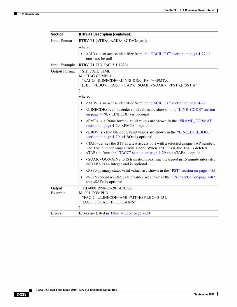
Chapter 3 TL1 Command DescriptionsTL1 Commands
Input Format RTRV-T1:[<TID>]:<AID>:<CTAG>[::::];
where:
• <AID> is an access identifier from the “FACILITY” section on page 4-22 and must not be null
Input Example RTRV-T1:TID:FAC-2-1:1223;
Output Format SID DATE TIMEM CTAG COMPLD “<AID>::[LINECDE=<LINECDE>,][FMT=<FMT>,] [LBO=<LBO>,][TACC=<TAP>,][SOAK=<SOAK>]:<PST>,[<SST>]”;
where:
• <AID> is an access identifier from the “FACILITY” section on page 4-22
• <LINECDE> is a line code; valid values are shown in the “LINE_CODE” section on page 4-70, <LINECDE> is optional
• <FMT> is a frame format; valid values are shown in the “FRAME_FORMAT” section on page 4-69, <FMT> is optional
• <LBO> is a line buildout; valid values are shown in the “LINE_BUILDOUT” section on page 4-70, <LBO> is optional
• <TAP> defines the STS as a test access port with a selected unique TAP number. The TAP number ranges from 1–999. When TACC is 0, the TAP is deleted. <TAP> is from the “TACC” section on page 4-29 and <TAP> is optional
• <SOAK> OOS-AINS to IS transition soak time measured in 15 minute intervals; <SOAK> is an integer and is optional
• <PST> primary state; valid values are shown in the “PST” section on page 4-85
• <SST> secondary state; valid values are shown in the “SST” section on page 4-87 and <SST> is optional
Output Example
TID-000 1998-06-20 14:30:00M 001 COMPLD “FAC-2-1::LINECDE=AMI,FMT=ESF,LBO=0-131, TACC=8,SOAK=10:OOS,AINS”;
Errors Errors are listed in Table 7-30 on page 7-20.
Section RTRV-T1 Description (continued)
3-238Cisco ONS 15454 and Cisco ONS 15327 TL1 Command Guide, R4.0
September 2004

Chapter 3 TL1 Command DescriptionsTL1 Commands
3.4.173 RTRV-T3: Retrieve T3 This command retrieves the facility properties of a DS3 and a DS3XM card.
(The facilities are on the XTC card for the ONS 15327)
Notes:
1. CTC can set the FMT attribute of a DS3(N)E line to autoprovision to set the framing based on the framing is coming in. This would result in the FMT field being blanked out for a few seconds blanked forever for a preprovisioned DS3(N)E card on CTC.
2. The autoprovision is not considered a valid DS3 framing type. It is used only to trigger an autosense and subsequent autoprovisioning of a valid DS3 framing type (unframed, M23, C-BIT).
3. TL1 does not have the autoprovision mode according to GR-199. TL1 maps/returns the autoprovision to be the unframed framing type.
Section RTRV-T3 Description
Category Ports
Security Retrieve
Related Messages
ED-<OCN_TYPE> RST-<MOD2_IO>ED-DS1 RTRV-<OCN_TYPE>ED-EC1 RTRV-DS1ED-G1000 RTRV-EC1ED-T1 RTRV-G1000ED-T3 RTRV-T1RMV-<MOD2_IO>
Input Format RTRV-T3:[<TID>]:<AID>:<CTAG>[::::];
where:
• <AID> is the access identifier from the “FACILITY” section on page 4-22 and must not be null
Input Example RTRV-T3:CISCO:FAC-1-2:123;
3-239Cisco ONS 15454 and Cisco ONS 15327 TL1 Command Guide, R4.0
September 2004
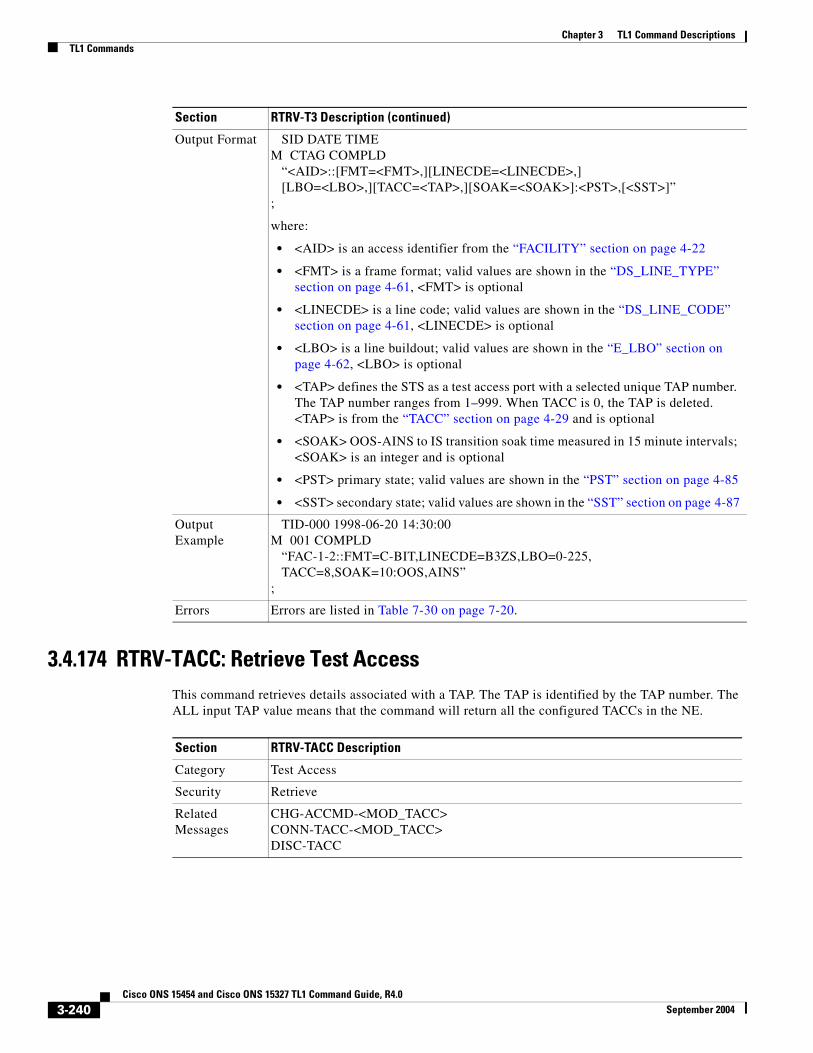
Chapter 3 TL1 Command DescriptionsTL1 Commands
3.4.174 RTRV-TACC: Retrieve Test AccessThis command retrieves details associated with a TAP. The TAP is identified by the TAP number. The ALL input TAP value means that the command will return all the configured TACCs in the NE.
Output Format SID DATE TIMEM CTAG COMPLD “<AID>::[FMT=<FMT>,][LINECDE=<LINECDE>,] [LBO=<LBO>,][TACC=<TAP>,][SOAK=<SOAK>]:<PST>,[<SST>]”;
where:
• <AID> is an access identifier from the “FACILITY” section on page 4-22
• <FMT> is a frame format; valid values are shown in the “DS_LINE_TYPE” section on page 4-61, <FMT> is optional
• <LINECDE> is a line code; valid values are shown in the “DS_LINE_CODE” section on page 4-61, <LINECDE> is optional
• <LBO> is a line buildout; valid values are shown in the “E_LBO” section on page 4-62, <LBO> is optional
• <TAP> defines the STS as a test access port with a selected unique TAP number. The TAP number ranges from 1–999. When TACC is 0, the TAP is deleted. <TAP> is from the “TACC” section on page 4-29 and is optional
• <SOAK> OOS-AINS to IS transition soak time measured in 15 minute intervals; <SOAK> is an integer and is optional
• <PST> primary state; valid values are shown in the “PST” section on page 4-85
• <SST> secondary state; valid values are shown in the “SST” section on page 4-87
Output Example
TID-000 1998-06-20 14:30:00M 001 COMPLD “FAC-1-2::FMT=C-BIT,LINECDE=B3ZS,LBO=0-225, TACC=8,SOAK=10:OOS,AINS”;
Errors Errors are listed in Table 7-30 on page 7-20.
Section RTRV-T3 Description (continued)
Section RTRV-TACC Description
Category Test Access
Security Retrieve
Related Messages
CHG-ACCMD-<MOD_TACC>CONN-TACC-<MOD_TACC>DISC-TACC
3-240Cisco ONS 15454 and Cisco ONS 15327 TL1 Command Guide, R4.0
September 2004

Chapter 3 TL1 Command DescriptionsTL1 Commands
Input Format RTRV-TACC:[<TID>]:<TAP>:<CTAG>;
where:
• <TAP> indicates the assigned numeric number for the AID being used as a TAP. The TAP number must be an integer with a range of 1–999. The ALL TAP value means that the command will return all the configured TACCs in the NE. <TAP> is a string and must not be null
Input Example RTRV-TACC:CISCO:241:CTAG;
Output Format SID DATE TIMEM CTAG COMPLD “<TAP>:<TACC_AID1>,<TACC_AID2>,[<MD>],[<E_CONN>],[<F_CONN>]”;
where:
• <TAP> indicates the assigned numeric number for the AID being used as a TAP; <TAP> is a string
• <TACC_AID1> is the STS or VT AID that was designated as a test access point and assigned to the TAP; <TACC_AID1> is from the “ALL” section on page 4-10
• <TACC_AID2> is the STS or VT AID that was designated as a test access point and assigned to the TAP+1; <TACC_AID2> is from the “ALL” section on page 4-10
• <MD> indicates the test access mode. It identifies the status of the circuit connected to the TACC. Valid values are shown in the “TACC_MODE” section on page 4-92
• <E_CONN> indicates the E side STS or VT AID of a circuit connected to the TACC or under test; <E_CONN> is from the “ALL” section on page 4-10 and is optional
• <F_CONN> indicates the F side STS or VT AID of a circuit connected to the TACC or under test; <F_CONN> is from the “ALL” section on page 4-10
Output Example
TID-000 1998-06-20 14:30:00M 001 COMPLD “241:STS-2-1,STS-2-2,MONE,STS-12-1,STS-13-1”;
Errors Errors are listed in Table 7-30 on page 7-20.
Section RTRV-TACC Description (continued)
3-241Cisco ONS 15454 and Cisco ONS 15327 TL1 Command Guide, R4.0
September 2004
Chapter 3 TL1 Command DescriptionsTL1 Commands
3.4.175 RTRV-TH-<MOD2>: Retrieve Threshold (CLNT, DS1, EC1, OC3, OC12, OC48, OC192, OCN, STS1, STS3C, STS6C, STS9C, STS12C, STS24C, STS48C, STS192C, T1, T3, VT1)
See Table 4-11 on page 4-6 for supported modifiers by platform.
This command retrieves the threshold level of one or more monitored parameters.
Notes:
1. After the BLSR switching, the working path is switched out, the traffic goes through the protection path and the threshold can be retrieved from the protection path.
2. If there is a STS PCA on the protection path, during the BLSR switching, the PCA path is pre-emptive; sending this command on the protection path after BLSR switch, the command returns the PMs off the protection path, not from the PCA path.
The message is issued to retrieve the thresholds for PM and the alarm thresholds. If it is used to retrieve the alarm thresholds, the time-period is not applicable.
The presentation rules are as follows: Client port only–Laser, Alarm and SONET Thresholds are applicable and will be displayed. Laser and alarm thresholds are only for Near End. If the card payload is in SONET mode, then SONET Thresholds will be displayed. The Receiver Temperature Montypes (RXT) are only applicable to the Trunk Port. The Transceiver Voltage Montypes (XCVR) are not applicable, though it is displayed or handled.
Laser and Alarm thresholds are always available. Laser and alarm thresholds are only for Near End. If G.709 is enabled, then the OTN thresholds will be displayed. If G.709 is enabled and FEC is enabled, then the FEC thresholds will be displayed. If the card payload is in SONET mode, then SONET Thresholds will be displayed. The Transceiver Voltage Montypes (XCVR) are not applicable, though it is displayed or handled.
See the “Provisioning Rules for MXP_2.5G_10G and TXP_MR_10G Cards” section on page 1-8 for specific MXP/TXP card provisioning rules.
Section RTRV-TH-<MOD2> Description
Category Performance
Security Retrieve
Related Messages
ALW-PMREPT-ALL RTRV-PMMODE-<STS_PATH>INH-PMREPT-ALL RTRV-PMSCHED-<MOD2>INIT-REG-<MOD2> RTRV-PMSCHED-ALLINIT-REG-G1000 SCHED-PMREPT-<MOD2>REPT PM <MOD2> SET-PMMODE-<STS_PATH>RTRV-PM-<MOD2> SET-TH-<MOD2>
3-242Cisco ONS 15454 and Cisco ONS 15327 TL1 Command Guide, R4.0
September 2004

Chapter 3 TL1 Command DescriptionsTL1 Commands
Input Format RTRV-TH-<MOD2>:[<TID>]:<AID>:<CTAG>::[<MONTYPE>],[<LOCN>],<TMPER>[::];
where:
• <AID> is an access identifier from the “ALL” section on page 4-10 and must not be null
• <MONTYPE> is the monitored type and defaults to CVL; valid values are shown in the “ALL_MONTYPE” section on page 4-33. A null value is equivalent to ALL.
Note <MONTYPE> defaults to: CVL for OCN, EC1 and DSN, ESP for STSp, UASV for VT1, AISSP for DS1 layer of DS3XM. LOCN defaults to NEND. TMPER defaults to 15 minutes.
• <LOCN> is the location; valid values are shown in the “LOCATION” section on page 4-71. A null value is equivalent to ALL
• <TMPER> indicates the accumulation time period; valid values are shown in the “TMPER” section on page 4-93 and <TMPER> must not be null
Input Example RTRV-TH-T3:CISCO:FAC-1-3:1234::CVL,NEND,15-MIN;
Output Format SID DATE TIMEM CTAG COMPLD “<AID>,[<AIDTYPE>]:<MONTYPE>,[<LOCN>],,<THLEV>,[<TMPER>]”;
where:
• <AID> is from the “ALL” section on page 4-10
• <AIDTYPE> specifies the type of AID; valid values are shown in the “MOD2B” section on page 4-74, <AIDTYPE> is optional
• <MONTYPE> indicates the monitored type; valid values are shown in the “ALL_MONTYPE” section on page 4-33
• <LOCN> is a location; valid values are shown in the “LOCATION” section on page 4-71, <LOCN> is optional
• <THLEV> is the threshold value and is a float; <THLEV> is an integer
• <TMPER> is the accumulation time period for the PM information; valid values are shown in the “TMPER” section on page 4-93, <TMPER> is optional
Output Example
TID-0001998-06-20 14:30:00M 001 COMPLD “FAC-1-3,DS3:CVL,NEND,,1,15-MIN”;
Errors Errors are listed in Table 7-30 on page 7-20.
Section RTRV-TH-<MOD2> Description (continued)
3-243Cisco ONS 15454 and Cisco ONS 15327 TL1 Command Guide, R4.0
September 2004

Chapter 3 TL1 Command DescriptionsTL1 Commands
3.4.176 RTRV-TOD: Retrieve Time of Day This command retrieves the system date and time at the instant when the command was executed. The time returned is in Coordinated Universal Time (UTC).
Section RTRV-TOD Description
Category System
Security Retrieve
Related Messages
ALW-MSG-ALL REPT EVT FXFRAPPLY RTRV-HDRCOPY-RFILE RTRV-INVED-DAT RTRV-MAP-NETWORKED-NE-GEN RTRV-NE-GENED-NE-SYNCN RTRV-NE-IPMAPINH-MSG-ALL RTRV-NE-SYNCNINIT-SYS SET-TOD
Input Format RTRV-TOD:[<TID>]::<CTAG>;
Input Example RTRV-TOD:CAZADERO::230;
Output Format SID DATE TIMEM CTAG COMPLD “<YEAR>,<MONTH>,<DAY>,<HOUR>, <MINUTE>,<SECOND>,<TMTYPE>”;
where:
• <YEAR> is the current calendar year and is a string
• <MONTH> is the month of the year and ranges from 01–12; <MONTH> is a string
• <DAY> is the day of the month and ranges from 01–31; <DAY> is a string
• <HOUR> is the hour of the day and ranges from 00–23; <HOUR> is a string
• <MINUTE> is the minute of the hour and ranges from 00–59; <MINUTE> is a string
• <SECOND> is the second of the minute and ranges from 00–59; <SECOND> is a string
• <TMTYPE> identifies the time zone and is a string
Output Example
TID-000 1998-06-20 14:30:00M 001 COMPLD “1998,05,08,17,01,33,UTC”;
Errors Errors are listed in Table 7-30 on page 7-20.
3-244Cisco ONS 15454 and Cisco ONS 15327 TL1 Command Guide, R4.0
September 2004

Chapter 3 TL1 Command DescriptionsTL1 Commands
3.4.177 RTRV-TRC-<OCN_BLSR>: Retrieve Trace Client (OC12, OC192, OC48)See Table 4-11 on page 4-6 for supported modifiers by platform.
This command retrieves the valid J1 expected trace string, retrieved trace string, trace mode, C2 byte, and STS bandwidth of the OCn port only if the port has a BLSR.
Note This command only applies to OC48AS and OC192 cards.
Note Sending this command over unsupported BLSR path trace cards, or unequipmented cards will result in a J1 Trace Not Supported On This Card (IIAC) error.
Section RTRV-TRC-<OCN_BLSR> Description
Category BLSR
Security Retrieve
Related Messages
ED-<STS_PATH>RTRV-<STS_PATH>,RTRV-PTHTRC-<STS_PATH>
Input Format RTRV-TRC-<OCN_BLSR>:[<TID>]:<AID>:<CTAG>;
where:
• <AID> is the AID from the “FACILITY” section on page 4-22 and must not be null
Input Example RTRV-TRC-OC48:CISCO:FAC-6-1:238;
Output Format SID DATE TIMEM CTAG COMPLD “<AID>::[LEVEL=<LEVEL>,][EXPTRC=<EXPTRC>,][INCTRC=<INCTRC>,] [TRCMODE=<TRCMODE>,][C2=<C2>]”;
where:
• <AID> is an access identifier from the “STS” section on page 4-24
• <LEVEL> indicates the rate of the cross connected channel; valid values are shown in the “STS_PATH” section on page 4-88. <LEVEL> is optional
• <EXPTRC> indicates the expected path trace message (J1) contents. <EXPTRC> is any 64-character string, including the terminating CR (carriage return) and LF (line feed). <EXPTRC> is a string and is optional
• <INCTRC> indicates the incoming path trace message contents. <INCTRC> is any 64-character string, including the CR and LF. <INCTRC> is a string and is optional
• <TRCMODE> indicates the trace mode; valid values are shown in the “TRCMODE” section on page 4-94 and <TRCMODE> is optional
• <C2> indicates C2 Byte Hex Code; valid values are shown in the “C2_BYTE” section on page 4-44 and <C2> is optional
3-245Cisco ONS 15454 and Cisco ONS 15327 TL1 Command Guide, R4.0
September 2004

Chapter 3 TL1 Command DescriptionsTL1 Commands
3.4.178 RTRV-TRC-CLNT: Retrieve Trace ClientThis command retrieves the SONET J0 Section sent trace string, expected trace string, received trace string, trace mode, and the trace level for the client facility.
The following rules apply: Client port–only J0 Section trace applies. The J0 Section trace applies only if the card termination mode is not transparent and the payload is SONET/SDH.
Depending on the settings, the following filtering applies: If no TRCLEVEL is provided, all TRCLEVELS are reported as applicable. If TRCLEVEL is provided and no MSGTYPE is provided, all applicable MSGTYPES for the given level is displayed. If no MSGTYPE is provided, all MSGTYPES are reported as applicable. If a MSGTYPE is provided without a TRCLEVEL, then the given MSGTYPE for all TRCLEVELS are displayed.
See the “Provisioning Rules for MXP_2.5G_10G and TXP_MR_10G Cards” section on page 1-8 for specific MXP/TXP card provisioning rules.
Output Example
TID-000 1998-06-20 14:30:00M 001 COMPLD “STS-6-1-25::LEVEL=STS1,EXPTRC=“EXPTRCSTRING”,INCTRC= “INCTRCSTRING”,TRCMODE=AUTO,C2=0X04”;
Errors Errors are listed in Table 7-30 on page 7-20.
Section RTRV-TRC-<OCN_BLSR> Description (continued)
Section RTRV-TRC-CLNT Description
Category DWDM
Security Retrieve
Related Messages
ED-TRC-CLNTED-DWDMRTRV-DWDMED-CLNTRTRV-CLNT
Input Format RTRV-TRC-CLNT:[<TID>]:<SRC>:<CTAG>::[<MSGTYPE>],[<TRCLEVEL>][::];
where:
• <SRC> is the AID from the “FACILITY” section on page 4-22 and must not be null
• <MSGTYPE> is the type of trace message to be retrieved. Valid values for <MSGTYPE> are shown in the “MSGTYPE” section on page 4-77. A null value is equivalent to ALL
• <TRCLEVEL> is the level at which the trace information is handled. Valid values are shown in the “TRCLEVEL” section on page 4-94 and a null value is equivalent to ALL
Input Example RTRV-TRC-CLNT:CISCO:FAC-2-1:100::EXPTRC,J0-SEC;
3-246Cisco ONS 15454 and Cisco ONS 15327 TL1 Command Guide, R4.0
September 2004

Chapter 3 TL1 Command DescriptionsTL1 Commands
3.4.179 RTRV-TRC-OCH: Retrieve Trace Optical ChannelThis command retrieves the sent trace string, expected trace string, received trace string, trace mode, and the trace level for the SONET J0 Section, the TTI PATH and SECTION monitoring levels of the DWDM facility.
The following rules apply: Client port–only the J0 Section trace applies. The J0 Section trace applies only if the card termination mode is not transparent and the payload is SONET/SDH. On the DWDM port the J0 Section trace, the TTI Path, Section trace monitoring point traces are allowed. The J0 Section trace is allowed only if the payload for the card is set to SONET/SDH. The J0 Section trace is allowed only if the card termination mode is not transparent. The TTI Path, Section trace is allowed only if the G.709 (DWRAP) is enabled.
Depending on the settings, the following filtering applies: If no TRCLEVEL is provided, all TRCLEVELS are reported as applicable. If TRCLEVEL is provided and no MSGTYPE is provided, all applicable MSGTYPES for the given level is displayed. If no MSGTYPE is provided, all MSGTYPES are reported as applicable. If a MSGTYPE is provided with out a TRCLEVEL, then the given MSGTYPE for all TRCLEVELS are displayed.
See the “Provisioning Rules for MXP_2.5G_10G and TXP_MR_10G Cards” section on page 1-8 for specific MXP/TXP card provisioning rules.
Output Format SID DATE TIMEM CTAG COMPLD “[TRCLEVEL=<TRCLEVEL>,][EXPTRC=<EXPTRC>,][TRC=<TRC>,] [INCTRC=<INCTRC>,][TRCMODE=<TRCMODE>,] [TRCFORMAT=<TRCFORMAT>]”;
where:
• Valid values for <TRCLEVEL> are shown in the “TRCLEVEL” section on page 4-94 and <TRCLEVEL> is optional
• <EXPTRC> expected path trace message to be retrieved; <EXPTRC> is a string and is optional
• <TRC> trace message sent; <TRC> is a string and is optional
• <INCTRC> incoming trace message to be retrieved; <INCTRC> is a string and is optional
• Valid values for <TRCMODE> are shown in the “ALS_MODE” section on page 4-41 and <TRCMODE> is optional
• Valid values for <TRCFORMAT> are shown in the “TRCFORMAT” section on page 4-94 and <TRCFORMAT> is optional
Output Example
TID-000 1998-06-20 14:30:00M 001 COMPLD “TRCLEVEL=J0-SEC,EXPTRC=“AAA”,TRC=“AAA”,INCTRC=“AAA”, TRCMODE=MAN,TRCFORMAT=16-BYTE”;
Errors Errors are listed in Table 7-30 on page 7-20.
Section RTRV-TRC-CLNT Description (continued)
3-247Cisco ONS 15454 and Cisco ONS 15327 TL1 Command Guide, R4.0
September 2004

Chapter 3 TL1 Command DescriptionsTL1 Commands
Section RTRV-TRC-OCH Description
Category DWDM
Security Retrieve
Related Messages
ED-TRC-OCHED-DWDMRTRV-DWDMED-OCHRTRV-OCH
Input Format RTRV-TRC-OCH:[<TID>]:<SRC>:<CTAG>::[<MSGTYPE>],[<TRCLEVEL>][::];
where:
• <SRC> is the AID from the “CHANNEL” section on page 4-19 and must not be null
• <MSGTYPE> is the type of trace message to be retrieved. Valid values for <MSGTYPE> are shown in the “MSGTYPE” section on page 4-77. A null value is equivalent to ALL
• <TRCLEVEL> is the level at which the trace information is handled. Valid values are shown in the “TRCLEVEL” section on page 4-94 and a null value is equivalent to ALL
Input Example RTRV-TRC-OCH:CISCO:CHAN-2-2:100::EXPTRC,PATH;
Output Format SID DATE TIMEM CTAG COMPLD “[TRCLEVEL=<TRCLEVEL>,][EXPTRC=<EXPTRC>,][TRC=<TRC>,] [INCTRC=<INCTRC>,][TRCMODE=<TRCMODE>,] [TRCFORMAT=<TRCFORMAT>]”;
where:
• <TRCLEVEL> level at which the trace information is handled; valid values are shown in the “TRCLEVEL” section on page 4-94 and <TRCLEVEL> is optional
• <EXPTRC> expected path trace message to be retrieved; <EXPTRC> is a string and is optional
• <TRC> trace message sent; <TRC> is a string and is optional
• <INCTRC> incoming trace message to be retrieved; <INCTRC> is a string and is optional
• <TRCMODE> indicates the trace mode; valid values are shown in the “TRCMODE” section on page 4-94 and <TRCMODE> is optional
• <TRCFORMAT> is the size of the trace message. In SONET/SDH mode, only 1 or 16 bytes are applicable for the J0 section trace. The TT1 level trace is only 64 bytes. Valid values are shown in the “TRCFORMAT” section on page 4-94 and <TRCFORMAT> is optional
3-248Cisco ONS 15454 and Cisco ONS 15327 TL1 Command Guide, R4.0
September 2004

Chapter 3 TL1 Command DescriptionsTL1 Commands
3.4.180 RTRV-UCP-CC: Retrieve Unified Control Plane Control Channel(Cisco ONS 15454 only)
This command creates a UCP IP control channel attributes.
The ALL AID is used for UCP retrieving command input only. A NULL AID in the IPCC’s retrieval command defaults to the ALL AID, which returns all the IPCCs of the node.
Retrieve all of the UCP IPCCs example:
RTRV-UCP-CC:::A;
Notes:
1. If the control channel is not found, a SRQN (Status, Invalid Request) error message is returned.
2. If the IPCC type is ROUTED (CCTYPE=ROUTED), both MTU and CRCMD fields are grayed out.
Output Example
TID-000 1998-06-20 14:30:00M 001 COMPLD “TRCLEVEL=SEC,EXPTRC=“AAA”,TRC=“AAA”,INCTRC=“AAA”, TRCMODE=MAN,TRCFORMAT=64-BYTE”;
Errors Errors are listed in Table 7-30 on page 7-20.
Section RTRV-TRC-OCH Description (continued)
Section RTRV-UCP-CC Description
Category UCP
Security Retrieve
Related Messages
DLT-UCP-CC ENT-UCP-NBRDLT-UCP-IF REPT ALM UCPDLT-UCP-NBR REPT EVT UCPED-UCP-CC RTRV-ALM-UCPED-UCP-IF RTRV-COND-UCPED-UCP-NBR RTRV-UCP-IFED-UCP-NODE RTRV-UCP-NBRENT-UCP-CC RTRV-UCP-NODEENT-UCP-IF
Input Format RTRV-UCP-CC:[<TID>]:[<AID >]:<CTAG>[::::];
where:
<AID> indicates an individual IPCC ID. The ALL AID is used for UCP retrieving command input only. A NULL AID in the IPCCs retrieval command defaults to the ALL AID which returns all the IPCCs of the node. <AID> is from the “IPCC” section on page 4-16 and a null value is equivalent to ALL
Input Example RTRV-UCP-CC:CISCO:CC-9:CTAG;
3-249Cisco ONS 15454 and Cisco ONS 15327 TL1 Command Guide, R4.0
September 2004

Chapter 3 TL1 Command DescriptionsTL1 Commands
Output Format SID DATE TIMEM CTAG COMPLD “[<AID>]::NBRIX=<NBRIX>,CCTYPE=<CCTYPE>,[PORT=<PORT>,] LOCALCCID=<LOCALCCID>,LOCALIPCC=<LOCALIPCC>, REMOTECCID=<REMOTECCID>,[REMOTEIPCC=<REMOTEIPCC>,] LMPHELLOINT=<LMPHELLOINT>, OPERLMPHELLOINT=<OPERLMPHELLOINT>, LMPHELLODEADINT=<LMPHELLODEADINT>, OPERLMPHELLODEADINT=<OPERLMPHELLODEADINT>, [TUNMD=<TUNMD>,][MTU=<MTU>,][CRCMD=<CRCMD>]”;
where:
• <AID> indicates an individual IPCC ID; <AID> is from the “IPCC” section on page 4-16 and <AID> is optional
• <NBRIX> indicates the neighbor node index and is an integer
• <CCTYPE> indicates the type of the control channel; valid values are shown in the “UCP_IPCC_TYPE” section on page 4-97
• <PORT> indicates the port which the control channel is configured, while the CCTYPE is the type of SDCC; <PORT> is from the “FACILITY” section on page 4-22 and is optional
• <LOCALCCID> indicates the local control channel ID and is an integer
• <LOCALIPCC> indicates the local IP address of the control channel and is a string
• <REMOTECCID> indicates the remote control channel ID and is an integer
• <REMOTEIPCC> indicates the remote IP address of the control channel; <REMOTEIPCC> is a string and is optional
• <LMPHELLOINT> indicates the provisioned interval between hello messages sent by this node. <LMPHELLOINT> has a range of 1–10 seconds with a default of 5 seconds; <LMPHELLOINT> is an integer
• <OPERLMPHELLOINT> indicates the LMP hello interval negotiated between a node and it’s neighbor and the negotiated value is used during operation. This value is the negotiated, operational value of LMP Hello interval. This value is initialized to the hello Interval at the time of IPCC creation and is updated after the negotiation is done with the neighbor; <OPERLMPHELLOINT> is a float
• <LMPHELLODEADINT> indicates the control channel time-out interval (in milliseconds) by the neighbor if the neighbor does not receive the hello message, and defaults to 15 (with the range of 3–30). This interval has to be at least as large as the hello interval and is normally set to 3 times the hello interval. Its range is 3 seconds to 30 seconds with a default of 15 seconds. <LMPHELLODEADINT> is an integer
• <OPERLMPHELLODEADINT> indicates the operational value of the LMP interval negotiated between this node and its neighbor. This value is initialized to the helloDeadInterval at the time of IPCC creation and is updated after the negotiation is done with the neighbor; <OPERLMPHELLODEADINT> is a float
Section RTRV-UCP-CC Description (continued)
3-250Cisco ONS 15454 and Cisco ONS 15327 TL1 Command Guide, R4.0
September 2004

Chapter 3 TL1 Command DescriptionsTL1 Commands
3.4.181 RTRV-UCP-IF: Retrieve Unified Control Plane Interface(Cisco ONS 15454 only)
This command retrieves UCP interface attributes.
The local interface ID (LOCALIFID) is used by LMP/RSVP (Line Management Protocol/Resource reservation Protocol). If zero is passed in as the local Interface ID of the data link, then the node assigns a value for it. If the user specifies a non-zero value, then the node checks if that Interface ID is available and uses it.
If the UCP interface/data link control channel type is SDCC type, the local interface ID should be same as CCID.
Retrieve all of the UCP interfaces example:
RTRV-UCP-IF:::A;
Note If this command is sent twice or inputs invalid data, as SRQN (Status, Invalid Request) error message is returned.
Output Format (continued)
• <TUNMD> indicates the IP tunneling option. It defaults to disabled; valid values are shown in the “UCP_CC_TUN_MD” section on page 4-96 and <TUNMD> is optional
• <MTU> indicates the MTU size of this control channel; <MTU> is an integer and is optional
• <CRCMD> indicates the CRC mode for this control channel. It is applicable to IPCCs in SDCC type; valid values are shown in the “UCP_CRC_MODE” section on page 4-97 and <CRCMD> is optional
Output Example
TID-000 1998-06-20 14:30:00M 001 COMPLD “CC-9::NBRIX=8,CCTYPE=SDCC,PORT=FAC-2-1,LOCALCCID=9, LOCALIPCC=172.20.209.31,REMOTECCID=2, REMOTEIPCC=172.20.209.15,LMPHELLOINT=10, OPERLMPHELLOINT=10.00,LMPHELLODEADINT=30, OPERLMPHELLODEADINT=30.00,TUNMD=DISABLED, MTU=1500,CRCMD=16-BIT”;
Errors Errors are listed in Table 7-30 on page 7-20.
Section RTRV-UCP-CC Description (continued)
Section RTRV-UCP-IF Description
Category UCP
Security Retrieve
3-251Cisco ONS 15454 and Cisco ONS 15327 TL1 Command Guide, R4.0
September 2004

Chapter 3 TL1 Command DescriptionsTL1 Commands
Related Messages
DLT-UCP-CC ENT-UCP-NBRDLT-UCP-IF REPT ALM UCPDLT-UCP-NBR REPT EVT UCPED-UCP-CC RTRV-ALM-UCPED-UCP-IF RTRV-COND-UCPED-UCP-NBR RTRV-UCP-CCED-UCP-NODE RTRV-UCP-NBRENT-UCP-CC RTRV-UCP-NODEENT-UCP-IF
Input Format RTRV-UCP-IF:[<TID>]:[<AID>]:<CTAG>[::::];
where:
• <AID> indicates the interface port index of the data link; <AID> is from the “FACILITY” section on page 4-22 and a null value is equivalent to ALL
Input Example RTRV-UCP-IF:CISCO:FAC-2-1:CTAG;
Output Format SID DATE TIMEM CTAG COMPLD “[<AID>]::NBRIX=<NBRIX>,CCID=<CCID>,LOCALIFID=<LOCALIFID>, REMOTEIFID=<REMOTEIFID>,TNATYPE=<TNATYPE>, TNAADDR=<TNAADDR>,CORENETWORKID=<CORENETWORKID>”;
where:
• <AID> indicates the interface port index of the data link; <AID> is from the “FACILITY” section on page 4-22 and is optional
• <NBRIX> indicates a neighbor within the local node; <NBRIX> is an integer
• <CCID> indicates the control channel ID and is an integer
• <LOCALFID> indicates the local interface ID used by LMP/RSVP (line management protocol/resource reservation protocol); <LOCALFID> is an integer
• <REMOTEFID> indicates the interface ID on the neighbor’s side and in an integer
• <TNATYPE> indicates the TNA (transport network administered) type; valid values are shown in the “UCP_TNA_TYPE” section on page 4-97
• <TNAADDR> indicates the TNA IP address and is a string
• <CORENETWORKID> indicates the core network ID and is an integer
Output Example
TID-000 1998-06-20 14:30:00M 001 COMPLD “FAC-2-1::NBRIX=12,CCID=16,LOCALIFID=16,REMOTEIFID=5, TNATYPE=IPV4,TNAADDR=172.20.209.73,CORENETWORKID=9” ;
Errors Errors are listed in Table 7-30 on page 7-20.
Section RTRV-UCP-IF Description (continued)
3-252Cisco ONS 15454 and Cisco ONS 15327 TL1 Command Guide, R4.0
September 2004

Chapter 3 TL1 Command DescriptionsTL1 Commands
3.4.182 RTRV-UCP-NBR: Retrieve Unified Control Plane Neighbor(Cisco ONS 15454 only)
This command retrieves a UCP neighbor.
The default value of the node name can be overwritten by the TL1 user to a string in a maximum size of 20 characters. If the node name includes non-identified TL1 characters (e.g. space), the text string format with the double quotes is required.
The ALL AID is used for UCP retrieving command input only. A NULL AID in the retrieval command defaults to the ALL AID, which returns all the UCP neighbors of the node.
Retrieve all the UCP neighbors example:
RTRV-UCP-NBR:::A;
Section RTRV-UCP-NBR Description
Category UCP
Security Retrieve
Related Messages
DLT-UCP-CC ENT-UCP-NBRDLT-UCP-IF REPT ALM UCPDLT-UCP-NBR REPT EVT UCPED-UCP-CC RTRV-ALM-UCPED-UCP-IF RTRV-COND-UCPED-UCP-NBR RTRV-UCP-CCED-UCP-NODE RTRV-UCP-IFENT-UCP-CC RTRV-UCP-NODEENT-UCP-IF
Input Format RTRV-UCP-NBR:[<TID>]:[<AID>]:<CTAG>[::::];
where:
• <AID> indicates an individual neighbor AID of the UCP; <AID> is from the “NBR” section on page 4-16 and a null value is equivalent to ALL
Input Example RTRV-UCP-NBR:CISCO:NBR-8:CTAG;
3-253Cisco ONS 15454 and Cisco ONS 15327 TL1 Command Guide, R4.0
September 2004

Chapter 3 TL1 Command DescriptionsTL1 Commands
3.4.183 RTRV-UCP-NODE: Retrieve Unified Control Plane Node(Cisco ONS 15454 only)
This command retrieves UCP node level attributes.
The NODEID is the unique number used to identify the local node in LMP, RSVP messages sent to the neighbors. It defaults to the local ethernet interface address (ISA).
The retry initial interval (in seconds) is used for that have been released by the net work side. This interval has a range of 60 seconds (1 minute) to 1800 seconds (30 minutes), with a default value of 180 seconds.
Output Format SID DATE TIMEM CTAG COMPLD “<AID>::[NBRIX=<NBRIX>,][NODEID=<NODEID>,][NAME=<NAME>,] [NDEN=<NDEN>,][HELLOEN=<HELLOEN>,][HELLOINT=<HELLOINT>,] [REFREDEN=<REFREDEN>,][NUMRXMTS=<NUMRXMTS>]”;
where:
• <AID> indicates an individual neighbor AID of the UCP. The ALL AID and NODEID (IP address, e.g. “AAA.BB.CC.D”) are used for UCP retrieving command input only; <AID> is from the “NBR” section on page 4-16
• <NBRIX> indicates a neighbor within the local node; <NBRIX> is an integer and is optional
• <NODEID> indicates the neighbor node ID as received in RSVP, LMP messages from that node; <NODEID> is a string and is optional
• <NAME> is a string and is optional
• <NDEN> indicates if the neighbor discovery is enabled or not for this neighbor; valid values are shown in the “ON_OFF” section on page 4-79 and <NDEN> is optional
• <HELLOEN> indicates if the RSVP hello is enabled to this neighbor or not; valid values are shown in the “ON_OFF” section on page 4-79 and <HELLOEN> is optional
• <HELLOINT> indicates the interval between hello messages to the neighbor; <HELLOINT> is an integer and is optional
• <REFREDEN> indicates if the refresh reduction is enabled or not; valid values are shown in the “ON_OFF” section on page 4-79 and <REFREDEN> is optional
• <NUMRXMTS> indicates the maximum number of retransmits of each message; <NUMRXMTS> is not editable, is an integer and is optional
Output Example
TID-000 1998-06-20 14:30:00M 001 COMPLD “NBR-8::NBRIX=8,NODEID=192.168.100.52,NAME=NODE-B, NDEN=Y,HELLOEN=Y,HELLOINT=20,REFREDEN=N,NUMRXMTS=3” ;
Errors Errors are listed in Table 7-30 on page 7-20.
Section RTRV-UCP-NBR Description (continued)
3-254Cisco ONS 15454 and Cisco ONS 15327 TL1 Command Guide, R4.0
September 2004

Chapter 3 TL1 Command DescriptionsTL1 Commands
The retry max interval (in seconds) is used for released circuits. The node will back off exponentially from the initial retry interval to this maximum value of 600 seconds (10 minutes).
The restart time is used to be signaled to neighbors. It indicates the time taken by this node (in seconds) to restart. This timer has a range of 1 second to 10 seconds with a default of 5 seconds.
The recovery time is used to be signaled to neighbors. It indicates the time taken by this node (in seconds) to re-sync path, reservation state with a given neighbor. This timer has a range of 300 seconds (5 minutes) to 1800 seconds (30 minutes) and a default value of 600 seconds (10 minutes).
The transmit interval is used to retransmit un-acknowledged messages. This timer has a range of 1 second to 7 seconds with a default value of 1 second.
The refresh interval is used to refresh path, reservation state. This interval has a range of 30 seconds to 4060800 seconds (47 days) with a default value of 30 seconds.
The timeout RESV interval is used to wait for a reservation message in response to a PATH message. This interval has a range of 10–180 seconds with a default value of 60 seconds.
The timeout RESV CONF interval is used to wait for a RESV CONF message in response to a RESV message. This interval has a range of 10–180 seconds with a default value of 60 seconds.
The Source Deletion in progress is a timeout interval while the source is in the progress of cleanly deleting a call. This interval has a range of 10–180 seconds with a default of 60 seconds.
The Destination Deletion progress is a timeout interval while the destination is in the progress of cleanly deleting a call. This interval has a range of 10–180 seconds with a default value of 60 seconds.
Notes:
1. If the retry initial interval is set to zero, it will be interpreted as having the retry procedure disable.
2. The retry maximum interval has to be set to a higher value than the initial retry interval.
Section RTRV-UCP-NODE Description
Category UCP
Security Retrieve
Related Messages
DLT-UCP-CC ENT-UCP-NBRDLT-UCP-IF REPT ALM UCPDLT-UCP-NBR REPT EVT UCPED-UCP-CC RTRV-ALM-UCPED-UCP-IF RTRV-COND-UCPED-UCP-NBR RTRV-UCP-CCED-UCP-NODE RTRV-UCP-IFENT-UCP-CC RTRV-UCP-NBRENT-UCP-IF
Input Format RTRV-UCP-NODE:[<TID>]::<CTAG>[::::];
Input Example RTRV-UCP-NODE:CISCO::CTAG;
3-255Cisco ONS 15454 and Cisco ONS 15327 TL1 Command Guide, R4.0
September 2004
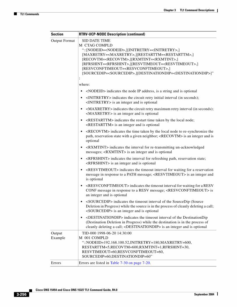
Chapter 3 TL1 Command DescriptionsTL1 Commands
Output Format SID DATE TIMEM CTAG COMPLD “::[NODEID=<NODEID>,][INITRETRY=<INITRETRY>,] [MAXRETRY=<MAXRETRY>,][RESTARTTM=<RESTARTTM>,] [RECOVTM=<RECOVTM>,][RXMTINT=<RXMTINT>,] [RFRSHINT=<RFRSHINT>,][RESVTIMEOUT=<RESVTIMEOUT>,] [RESVCONFTIMEOUT=<RESVCONFTIMEOUT>,] [SOURCEDIP=<SOURCEDIP>,][DESTINATIONDIP=<DESTINATIONDIP>]”;
where:
• <NODEID> indicates the node IP address, is a string and is optional
• <INITRETRY> indicates the circuit retry initial interval (in seconds); <INITRETRY> is an integer and is optional
• <MAXRETRY> indicates the circuit retry maximum retry interval (in seconds); <MAXRETRY> is an integer and is optional
• <RESTARTTM> indicates the restart time taken by the local node; <RESTARTTM> is an integer and is optional
• <RECOVTM> indicates the time taken by the local node to re-synchronize the path, reservation state with a given neighbor; <RECOVTM> is an integer and is optional
• <RXMTINT> indicates the interval for re-transmitting un-acknowledged messages; <RXMTINT> is an integer and is optional
• <RFRSHINT> indicates the interval for refreshing path, reservation state; <RFRSHINT> is an integer and is optional
• <RESVTIMEOUT> indicates the timeout interval for waiting for a reservation message in response to a PATH message; <RESVTIMEOUT> is an integer and is optional
• <RESVCONFTIMEOUT> indicates the timeout interval for waiting for a RESV CONF message in response to a RESV message; <RESVCONFTIMEOUT> is an integer and is optional
• <SOURCEDIP> indicates the timeout interval of the SourceDip (Source Deletion in Progress) while the source is in the process of cleanly deleting a call; <SOURCEDIP> is an integer and is optional
• <DESTINATIONDIP> indicates the timeout interval of the DestinationDip (Destination Deletion in Progress) while the destination is in the process of cleanly deleting a call; <DESTINATIONDIP> is an integer and is optional
Output Example
TID-000 1998-06-20 14:30:00M 001 COMPLD “::NODEID=192.168.100.52,INITRETRY=180,MAXRETRY=600, RESTARTTM=5,RECOVTM=600,RXMTINT=1,RFRSHINT=30, RESVTIMEOUT=60,RESVCONFTIMEOUT=60, SOURCEDIP=60,DESTINATIONDIP=60”
Errors Errors are listed in Table 7-30 on page 7-20.
Section RTRV-UCP-NODE Description (continued)
3-256Cisco ONS 15454 and Cisco ONS 15327 TL1 Command Guide, R4.0
September 2004

Chapter 3 TL1 Command DescriptionsTL1 Commands
3.4.184 RTRV-USER-SECU: Retrieve User SecurityThis command retrieves the security information of a specified user or list of users. The keyword ALL can be used to obtain a list of all users. For security reasons the password cannot be retrieved.
A Superuser can retrieve any user’s security information. A user with MAINT, PROV, or RTRV privileges can only retrieve their own information.
Note When using the keyword ALL, all users created for the system are displayed. This includes users created via CTC that are not legal and valid TL1 users (i.e., userids/passwords greater than 20 characters in length). Although displayed via the RTRV-USER-SECU command, these users will not be able to log into the TL1 environment.
Section RTRV-USER-SECU Description
Category Security
Security Superuser
Related Messages
ACT-USER ED-PIDCANC ED-USER-SECUCANC-USER ENT-USER-SECUDLT-USER-SECU REPT EVT SECU
Input Format RTRV-USER-SECU:[<TID>]:<UID>:<CTAG>;
where:
• <UID> the user ID or the keyword ALL. A non-superuser can only specify their own user ID; <UID> is a string and must not be null
Input Example RTRV-USER-SECU::CISCO15:1;
Output Format SID DATE TIMEM CTAG COMPLD “<UID>:,<UAP>”;
where:
• <UID> the user ID that was retrieved; <UID> is a string
• <UAP> the privilege of the user; valid values are shown in the “PRIVILEGE” section on page 4-83
Output Example
TID-000 1998-06-20 14:30:00M 001 COMPLD “CISCO15:,SUPER”;
Errors Errors are listed in Table 7-30 on page 7-20.
3-257Cisco ONS 15454 and Cisco ONS 15327 TL1 Command Guide, R4.0
September 2004

Chapter 3 TL1 Command DescriptionsTL1 Commands
3.4.185 RTRV-VT1: Retrieve VT1This command retrieves the attributes associated with a VT1 path.
Note RVRTV, RVTM, HOLDOFFTIMER and UPSRPTHSTATE parameters only apply to path protection configuration.
Section RTRV-VT1 Description
Category STS and VT Paths
Security Retrieve
Related Messages
ED-VT1
Input Format RTRV-VT1:[<TID>]:<SRC>:<CTAG>[::::];
where:
• <SRC> is an access identifier from the “VT1_5” section on page 4-30 and must not be null
Input Example RTRV-VT1:CISCO:VT1-2-1-4-1-2:123;
Output Format SID DATE TIMEM CTAG COMPLD “<VT>::[RVRTV=<RVRTV>,][RVTM=<RVTM>,] [HOLDOFFTIMER=<HOLDOFFTIMER>,][TACC=<TACC>] [UPSRPTHSTATE=<UPSRPTHSTATE>]:[<PST>],[<SST>]”
;
where:
• <VT> is an access identifier from the “VT1_5” section on page 4-30
• <RVRTV> is a revertive mode which only applies to a path protection configuration VT1 path. <RVRTV> defaults to N (non-revertive mode) when path protection configuration VT1 is created; valid values are shown in the “ON_OFF” section on page 4-79 and <RVRTV> is optional
• <RVTM> is a revertive time which only applies to a path protection configuration VT1 path. <RVTM> defaults to empty because <RVRTV> is N when path protection configuration VT1 is created. Valid values are shown in the “REVERTIVE_TIME” section on page 4-85 and <RVTM> is optional
• <HOLDOFFTIMER> is an integer and is optional
• <TACC> is from the “TACC” section on page 4-29 and is optional
• <UPSRPTHSTATE> indicates if the VT_AID is the working or standby path of a path protection configuration cross-connect; valid values are shown in the “STATUS” section on page 4-87 and <UPSRPTHSTATE> is optional
• <PST> primary state; valid values are shown in the “PST” section on page 4-85 and <PST> is optional
• <SST> secondary state; valid values are shown in the “SST” section on page 4-87 and <SST> is optional
3-258Cisco ONS 15454 and Cisco ONS 15327 TL1 Command Guide, R4.0
September 2004

Chapter 3 TL1 Command DescriptionsTL1 Commands
3.4.186 SCHED-PMREPT-<MOD2>: Schedule Performance Monitoring Report (CLNT, DS1, EC1, OC3, OC12, OC48, OC192, OCH, STS1, STS3C, STS6C, STS9C, STS12C, STS24C, STS48C, STS192C, T1, T3, VT1)
See Table 4-11 on page 4-6 for supported modifiers by platform.
This command schedules/reschedules the NE to report the performance monitoring data for a line facility or for an STS/VT path periodically, using the automatic REPT PM message. This command can also remove the previously created schedule.
The automatic performance monitoring reporting scheduled by this command is inhibited by default. ALW-PMREPT-ALL can be used to allow the NE to send the performance monitoring report. INH-PMREPT-ALL can be used to stop the NE from sending the performance monitoring report. The schedules created for the NE can be retrieved by RTRV-PMSCHED command.
The deletion of the schedule for the automatic performance monitoring reporting can be done by issuing SCHED-PMREPT-<MOD2> with the <NUMREPT> parameter equal to zero.
Notes:
1. The current maximum number of schedules allowed to be created for a NE is 1000. If this number of schedules has been created for the NE, an error message “Reach Limits Of MAX Schedules Allowed. Can Not Add More” will be returned if another schedule creation is attempted on the NE. Frequent use of automatic performance monitoring reporting will significantly degrade the performance of the NE.
2. A schedule cannot be created if the card associated with the schedule is not provisioned, or if the cross-connection associated with the schedule has not been created. However, a schedule is allowed to be deleted even if a card is not provisioned, or if the cross-connection has not been created.
3. The number of outstanding performance monitoring reports counter <NUMREPT> will not be decremented, and the scheduled automatic performance monitoring reporting will not start if the card associated with the schedule is not physically plugged into the slot.
4. An expired schedule would not be automatically removed. The SCHED-PMREPT command has to be issued with the <NUMREPT> parameter equal to zero in order to delete the expired schedule.
5. Identical schedules for an NE is not allowed. Two schedules are considered identical if they have the same AID, MOD2 type, performance monitor type, performance monitor level, location, direction and time period.
An error message “Duplicate Schedule” is returned when trying to create a schedule which is a duplicate of a existing schedule. However, if the existing schedule expires (with the parameter <NUMINVL> equal to zero when retrieved by the RTRV-PMSCHED command, i.e., no more performance monitoring reporting sent) the new schedule with the identical parameter will replace the existing schedule.
Output Example
TID-000 1998-06-20 14:30:00M 001 COMPLD “VT1-2-1-4-1-2::RVRTV=Y,RVTM=1.0,HOLDOFFTIMER=2000, TACC=8,UPSRPTHSTATE=ACT:OOS,AINS”
;
Errors Errors are listed in Table 7-30 on page 7-20.
Section RTRV-VT1 Description (continued)
3-259Cisco ONS 15454 and Cisco ONS 15327 TL1 Command Guide, R4.0
September 2004

Chapter 3 TL1 Command DescriptionsTL1 Commands
6. When a electrical or optical card is unprovisioned by the DLT-EQPT command, or a cross-connection is deleted by the DLT-CRS command, the schedules associated with that card or that cross-connection will be removed silently by the NE. This removal prevents another type of card or cross-connection with the same AID to be provisioned on the NE, and prevents the NE from trying to send automatic performance monitoring reports based on the existing schedules.
The card or cross connect can be unprovisioned or deleted through CTC. The schedules associated with that card or that cross-connection will also be removed silently by the NE.
7. When creating schedules on an ONS 15327 XTC card, only schedules against the working XTC card (in Slot 6) are allowed. An error message “Can Not Create Schedule On Protect Card” will be returned if you try to create a schedule on protect XTC card in Slot 5.
8. When you create a PM schedule, the minimum report interval should not be less than five minutes.
Section SCHED-PMREPT-<MOD2> Description
Category Performance
Security Maintenance
Related Messages
ALW-PMREPT-ALL RTRV-PMMODE-<STS_PATH>INH-PMREPT-ALL RTRV-PMSCHED-<MOD2>INIT-REG-<MOD2> RTRV-PMSCHED-ALLINIT-REG-G1000 RTRV-TH-<MOD2> REPT PM <MOD2> SET-PMMODE-<STS_PATH> RTRV-PM-<MOD2> SET-TH-<MOD2>
Input Format SCHED-PMREPT-<MOD2>:[<TID>]:<SRC>:<CTAG>::[<REPTINVL>],[<REPTSTATM>],[<NUMREPT>],,[<MONLEV>],[<LOCN>],,[<TMPER>],[<TMOFST>];
where:
• <SRC> is from the “ALL” section on page 4-10
• <REPTINVL> specifies how often a performance monitoring report is generated. The format for <REPTINVL> is VAL-UN; valid values for VAL (value) are:
– 1–31 if UN (units of time) is DAY
– 1–24 if UN is HR
– 1–1440 if UN is MIN
Examples are: 10-DAY, 12-HR, or 100-MIN. A null value for the input would default to 15-MIN. <REPTINVL> is a string
Note The minimum time for processing PM schedules is every five minutes. A <REPTINVL> value of less than five minutes will process every five minutes.
• <REPTSTATM> starting time for the performance monitoring report. The format is HOD-MOH, where HOD (hour of day) ranges from 0–23, and MOH (minute of hour) ranges from 0–59. If the input value of the starting time is smaller than the current time; for example, the input value is 5-30 (5:30 in the morning) and the current time is 10:30, then the reporting will be scheduled to start at 5:30 the next day. A null value defaults to the current time of day; <REPTSTATM> is a string
3-260Cisco ONS 15454 and Cisco ONS 15327 TL1 Command Guide, R4.0
September 2004

Chapter 3 TL1 Command DescriptionsTL1 Commands
3.4.187 SET-ATTR-CONT: Set Attribute ControlThis command sets the attributes associated with an external control. The attributes are used when an external control is operated or released. To send the attributes, use the RTRV-ATTR-CONT command.
Notes:
1. If the <CONTTYPE> parameter is not specified, the control specified by <AID> is unprovisioned.
2. A control should be unprovisioned before it is reprovisioned to another type of control.
• <NUMREPT> the number of reports that the schedule is expected to produce. A value of 0 is used to delete an existing identical schedule (see Note 5 above). If <NUMREPT> is null the schedule will be in effect forever until it is deleted. The value of <NUMREPT> will continue to be decremented even though the automatic performance monitoring reporting is inhibited; <NUMREPT> is an integer
• <MONLEV> discriminating level for the requested monitored parameter. It applies to all MONTYPE of the scheduled performance monitoring report. The format is LEV-DIRN; valid values for LEV are decimal numbers, and valid values for DIRN are as follows: UP Monitored parameter with values equal to or greater than the value of LEV will be reported. DN Monitored parameter with values equal to or less than the value of LEV will be reported. The null input defaults to 1-UP; <MONLEV> is a string
• <LOCN> the location being performance-monitored. The valid value is NEND or FEND. A null input defaults to NEND. FEND is not supported by all MOD2 types; valid values are shown in the “LOCATION” section on page 4-71
• <TMPER> the accumulation time period. It defaults to 15-MIN; valid values are shown in the “TMPER” section on page 4-93
• <TMOFST> the time offset from the end of the last complete accumulation time period to the beginning of the accumulation time period specified in TMPER. The format for is DAY-HR-MIN, where DAYS (days) range from 0–99, HR (hours) range from 0–23, and MIN (minutes) range from 0–59. A null value defaults to 0-0-0. Grouping of this parameter is not supported. <TMOFST> is a String.
Input Example SCHED-PMREPT-OC3:NE-NAME:FAC-3-1:123::60-MIN,15-30,100,,1-UP,NEND,,15-MIN,0-0-15;
Errors Errors are listed in Table 7-30 on page 7-20.
Section SCHED-PMREPT-<MOD2> Description (continued)
Section SET-ATTR-CONT Description
Category Environment Alarms and Controls
Security Provisioning
Related Messages
OPR-ACO-ALL RTRV-ATTR-CONTOPR-EXT-CONT RTRV-ATTR-ENVREPT ALM ENV RTRV-COND-ENVREPT EVT ENV RTRV-EXT-CONTRLS-EXT-CONT SET-ATTR-ENVRTRV-ALM-ENV
3-261Cisco ONS 15454 and Cisco ONS 15327 TL1 Command Guide, R4.0
September 2004

Chapter 3 TL1 Command DescriptionsTL1 Commands
3.4.188 SET-ATTR-ENV: Set Attribute EnvironmentThis command sets the attributes associated with an external control.
Notes:
1. If the <NTFCNCDE>, <ALMTYPE>, and <ALMMSG> parameters are omitted, the environmental alarm specified by <AID> is unprovisioned.
2. An alarm should be unprovisioned and you should wait for any raised alarm to clear before reprovisioning the alarm to another alarm type.
Input Format SET-ATTR-CONT:[<TID>]:<AID>:<CTAG>[::<CONTTYPE>];
where:
• <AID> identifies the external control for which attributes are being retrieved and is from the “ENV” section on page 4-20
• <CONTTYPE> is the type of control for which the attribute is being retrieved; valid values are shown in the “CONTTYPE” section on page 4-59. The default value is MISC
Input Example SET-ATTR-CONT:CISCO:ENV-OUT-1:123::AIRCOND;
Errors Errors are listed in Table 7-30 on page 7-20.
Section SET-ATTR-CONT Description (continued)
Section SET-ATTR-ENV Description
Category Environment Alarms and Controls
Security Provisioning
Related Messages
OPR-ACO-ALL RTRV-ATTR-CONTOPR-EXT-CONT RTRV-ATTR-ENVREPT ALM ENV RTRV-COND-ENVREPT EVT ENV RTRV-EXT-CONTRLS-EXT-CONT SET-ATTR-CONTRTRV-ALM-ENV
Input Format SET-ATTR-ENV:[<TID>]:<AID>:<CTAG>::[<NTFCNCDE>],[<ALMTYPE>],[<ALMMSG>];
where:
• <AID> is an access identifier from the “ENV” section on page 4-20 and must not be null
• <NTFCNCDE> is a notification code; valid values are shown in the “NOTIF_CODE” section on page 4-78. A null value is equivalent to ALL
• <ALMTYPE> is an alarm type for the environmental alarm; valid values are shown in the “ENV_ALM” section on page 4-62. A null value is equivalent to ALL
• <ALMMSG> is an alarm message and is a string. A null value is equivalent to ALL
Input Example SET-ATTR-ENV:CISCO:ENV-IN-1:123::MJ,OPENDR,\“OPEN DOOR\”
Errors Errors are listed in Table 7-30 on page 7-20.
3-262Cisco ONS 15454 and Cisco ONS 15327 TL1 Command Guide, R4.0
September 2004

Chapter 3 TL1 Command DescriptionsTL1 Commands
3.4.189 SET-PMMODE-<STS_PATH>: Set Performance Mode of PM Data Collection (STS1, STS3C, STS6C, STS9C, STS12C, STS24C, STS48C, STS192C)
See Table 4-11 on page 4-6 for supported modifiers by platform.
This command sets the mode and turns the PM data collection mode on or off. The Cisco ONS 15454 is capable of collecting and storing section, line and path PM data.
The PM mode and state of an entity are retrieved by using the RTRV-PMMODE command.
Notes:
1. The near end monitoring of the intermediate-path PM (IPPM) only supports OC-3, OC-12, OC-48, OC-48AS, OC-192, and EC-1 on STS Path.
2. The far end PM data collection is not supported for the ONS 15454 in this release.
3. This release of software will support only the Path (P) mode type PM parameters with this command, that is, this command is not applicable for Line (L) and Section (S) mode types.
The PM monitoring for Line (L) and Section (S) are supported by the ONS 15454, and the storing PM data is always performed.
Section SET-PMMODE-<STS_PATH> Description
Category Performance
Security Provisioning
Related Messages
ALW-PMREPT-ALL RTRV-PMSCHED-<MOD2>INH-PMREPT-ALL RTRV-PMSCHED-ALLINIT-REG-<MOD2> RTRV-TH-<MOD2>REPT PM <MOD2> SCHED-PMREPT-<MOD2>RTRV-PM-<MOD2> SET-TH-<MOD2>RTRV-PMMODE-<STS_PATH>
Input Format SET-PMMODE-<STS_PATH>:[<TID>]:<AID>:<CTAG>::<LOCN>,<MODETYPE>,[<PMSTATE>];
where:
• <AID> identifies the entity where the PM mode is being set; <AID> is from the “STS” section on page 4-24
• <LOCN> identifies the location to which the PM mode is to be set and only supports near end PM data collection; valid values are shown in the “LOCATION” section on page 4-71
• <MODETYPE> identifies the type of PM parameters; only the Path (P) PM parameter is supported and valid values are shown in the “PM_MODE” section on page 4-83
• <PMSTATE> directs the named PM mode type to turn On or Off and a null value defaults to On; valid values are shown in the “PM_STATE” section on page 4-83
Input Example SET-PMMODE-STS1:CISCO:STS-4-2:123::NEND,P,ON;
Errors Errors are listed in Table 7-30 on page 7-20.
3-263Cisco ONS 15454 and Cisco ONS 15327 TL1 Command Guide, R4.0
September 2004

Chapter 3 TL1 Command DescriptionsTL1 Commands
3.4.190 SET-TH-<MOD2>: Set Threshold (CLNT, DS1, EC1, OC3, OC12,OC48, OC192, OCH, STS1, STS3C, STS6C, STS9C, STS12C, STS24C, STS48C, STS192C,T1, T3, VT1)
See Table 4-11 on page 4-6 for supported modifiers by platform.
This command sets the threshold for PM and sets the alarm thresholds for the MXP/TXP cards. If this command is used to set the alarm thresholds, the time-period is not applicable.
The rules are as follows: The PM Thresholds have a default of NEND for the location. The Alarm Thresholds do not require or interpret the location. The TMPER is not applicable to alarm thresholds. The TMPER default is 15-MIN. The client ports only accept SONET, Laser and alarm MONTYPES. The trunk ports accept SONET, Laser, alarm, FEC, OTN MONTYPES. The Receiver Temperature Montypes (RXT) are only applicable to the trunk port. The Transceiver Voltage Montypes (XCVR) is not applicable, though it is displayed or handled.
See the “Provisioning Rules for MXP_2.5G_10G and TXP_MR_10G Cards” section on page 1-8 for specific MXP/TXP card provisioning rules.
Section SET-TH-<MOD2> Description
Category Performance
Security Provisioning
Related Messages
ALW-PMREPT-ALL RTRV-PMSCHED-<MOD2>INH-PMREPT-ALL RTRV-PMSCHED-ALLINIT-REG-<MOD2> RTRV-TH-<MOD2>REPT PM <MOD2> SCHED-PMREPT-<MOD2>RTRV-PM-<MOD2> SET-PMMODE-<STS_PATH>RTRV-PMMODE-<STS_PATH>
Input Format SET-TH-<MOD2>:[<TID>]:<AID>:<CTAG>::<MONTYPE>,<THLEV>,[<LOCN>],,[<TMPER>];
where:
• <AID> indicates the access identifier. All the STS, VT1, Facility and DS1 AIDs are supported and <AID> is from the “ALL” section on page 4-10
• <MONTYPE> is the monitored value; valid values are shown in the “ALL_MONTYPE” section on page 4-33
• <THLEV> is the threshold value and is a float; <THLEV> is an integer
• <LOCN> is the location; valid values are shown in the “LOCATION” section on page 4-71
• <TMPER> indicates the accumulation time period for the PM information; valid values are shown in the “TMPER” section on page 4-93
Input Example SET-TH-T3:CISCO:FAC-1-1:123::CVL,12,NEND,,15-MIN;
Errors Errors are listed in Table 7-30 on page 7-20.
3-264Cisco ONS 15454 and Cisco ONS 15327 TL1 Command Guide, R4.0
September 2004

Chapter 3 TL1 Command DescriptionsTL1 Commands
3.4.191 SET-TOD: Set Time of Day This command sets the system date and time for the NE. The year should be entered using four digits while the hour should be entered using a 24-hour time period (i.e., military time).
3.4.192 SW-DX-EQPT: Switch Duplex Equipment(Cisco ONS 15454 only)
This command switches an XC/XCVT/XC10G card with the mate card within the NE.
Note If sending a mode parameter with a value other than NORM, FRCD, or NULL, the IDNV (Input, Data Not Valid) error message will be returned.
Section SET-TOD Description
Category System
Security Provisioning
Related Messages
ALW-MSG-ALL RTRV-HDRAPPLY RTRV-INVCOPY-RFILE RTRV-MAP-NETWORKED-DAT RTRV-NE-GENED-NE-GEN RTRV-NE-IPMAPED-NE-SYNCN RTRV-NE-SYNCNINH-MSG-ALL RTRV-TODINIT-SYS
Input Format SET-TOD:[<TID>]::<CTAG>::<YEAR>,<MONTH>,<DAY>,<HOUR>,<MINUTE>,<SECOND>,[<DIFFERENCE>][:DST=<DST>];
where:
• <YEAR> is the current calendar year and is an integer
• <MONTH> is the month of the year and ranges from 01–12; <MONTH> is an integer
• <DAY> is the day of the month and ranges from 01–31; <DAY> is an integer
• <HOUR> is the hour of the day and ranges from 00–23; <HOUR> is an integer
• <MINUTE> is the minute of the hour and ranges from 00–59; <MINUTE> is an integer
• <SECOND> is the second of the minute and ranges from 00–59; second is an integer
• <DIFFERENCE> is the number of minutes off UTC and is an integer
• <DST> identifies if the time is a Daylight Saving Time (Y) or not (N); valid values are shown in the “ON_OFF” section on page 4-79
Input Example SET-TOD:CAZADERO::240::1998,05,08,13,18,55,480:DST=Y;
Errors Errors are listed in Table 7-30 on page 7-20.
3-265Cisco ONS 15454 and Cisco ONS 15327 TL1 Command Guide, R4.0
September 2004

Chapter 3 TL1 Command DescriptionsTL1 Commands
3.4.193 SW-TOPROTN-EQPT: Switch to Protection Equipment(Cisco ONS 15454 only)
This command performs an equipment unit protection switch.
This command is used for non-SONET line cards (e.g. DS1, DS3, DS3XM, and EC1). DS1 and DS3 cards have 1:1 and 1:N equipment protection. DS3XM and EC1 cards have only 1:1 equipment protection.
This command will switch the traffic from the working card specified in the AID to the protect card.
There is a priority for the switch to protection commands. In a 1:N protection group with N > 1, consider two working cards - A and B. Card A is switched to the protect card with the SW-TOPROTN command. If card B is pulled from the system, the protect card will carry the traffic of card B and card A will raise the FAILTOSW condition and carry traffic. When card B is replaced and the revert timer expires, card B will carry traffic and card A will switch to the protect card. The FAILTOSW condition on card A will be cleared. Note:1:N protection groups in the system are always revertive.
In a revertive protection group, the unit specified by the AID will raise the standing condition of WKSWPR if the command were executed without an error. In a non-revertive protection group, the unit specified by the AID will raise the transient condition of WKSWPR if the command were executed without an error.
Notes:
1. The default PROTID is the protecting unit if there is only one protection unit per protection group in the NE, otherwise a DENY error message will be responsed.
2. This command only supports one value of the <DIRN> parameter - BTH or null. A command with any other value is considered an incorrect use of the command. An IDNV (Input, Data Not Valid) error message will be responsed.
Section SW-DX-EQPT Description
Category Equipment
Security Maintenance
Related Messages
ALW-SWDX-EQPT INH-SWTOWKG-EQPTALW-SWTOPROTN-EQPT REPT ALM EQPTALW-SWTOWKG-EQPT REPT EVT EQPTDLT-EQPT RTRV-ALM-EQPTED-EQPT RTRV-COND-EQPTENT-EQPT RTRV-EQPTINH-SWDX-EQPT SW-TOPROTN-EQPTINH-SWTOPROTN-EQPT SW-TOWKG-EQPT
Input Format SW-DX-EQPT:[<TID>]:<AID>:<CTAG>::[<MODE>][,];
where:
• <AID> identifies the equipment (XC/XCVT/XC10G) unit in the NE that is to be switched with its mate unit; <AID> is from the “EQPT” section on page 4-21
• Valid values for <MODE> are shown in the “CMD_MODE” section on page 4-46
Input Example SW-DX-EQPT:CISCO:SLOT-1:123::FRCD;
Errors Errors are listed in Table 7-30 on page 7-20.
3-266Cisco ONS 15454 and Cisco ONS 15327 TL1 Command Guide, R4.0
September 2004

Chapter 3 TL1 Command DescriptionsTL1 Commands
3. This command is not used for the common control (TCC+/TCC2 or XC/XCVT/XC10G) cards. A command on a common control card will generate an IIAC (Input, Invalid Access Identifier) error message. To use the common control card switching commands, use the SW-DX-EQPT and ALW-SWDX-EQPT commands.
4. This command is not used for SONET (OCN) cards. A command on a SONET card will generate an IIAC (Input, Invalid Access Identifier) error message. To use a SONET card switching command, use the OPR-PROTNSW and RLS-PROTNSW commands.
5. If this command is used on a card that is not in a protection group, the SNVS (Status, Not in Valid State) error message will be responsed.
6. If this command is sent to a missing working card, the SWFA (Status, Working Unit Failed) error message will be responsed.
7. If this command is used on a protection card, the IIAC (Input, Invalid Access Identifier) error message will be responsed.
8. If sending a mode parameter with a value other than NORM, FRCD, or null, the IDNV (Input, Data Not Valid) error message will be responsed.
9. If sending the SW-TOPROTN command to a working card when the working card has raised INHSWPR, the SWLD (Status, Working Unit Locked) error message will be responsed.
10. If sending the SW-TOPROTN command to a working card when the protection card has raised INHSWPR, the SPLD (Status, Protection Unit Locked) error message will be responsed.
11. If sending the SW-TOPROTN command to an active working card when the protect card is already carrying traffic. This only occurs in a 1:N protection group with N greater than one, the SNVS (Status, Not in Valid State) error message will be responsed.
12. If sending the SW-TOPROTN command to an active working card when the protect card is failed or missing, the SPFA (Status, Protection Unit Failed) error message will be responsed.
13. If sending this command to a standby working card, the SNVS (Status, Not in Valid State) error message will be responsed.
Section SW-TOPROTN-EQPT Description
Category Equipment
Security Maintenance
Related Messages
ALW-SWDX-EQPT INH-SWTOWKG-EQPTALW-SWTOPROTN-EQPT REPT ALM EQPTALW-SWTOWKG-EQPT REPT EVT EQPTDLT-EQPT RTRV-ALM-EQPTED-EQPT RTRV-COND-EQPTENT-EQPT RTRV-EQPTINH-SWDX-EQPT SW-DX-EQPTINH-SWTOPROTN-EQPT SW-TOWKG-EQPT
3-267Cisco ONS 15454 and Cisco ONS 15327 TL1 Command Guide, R4.0
September 2004

Chapter 3 TL1 Command DescriptionsTL1 Commands
3.4.194 SW-TOWKG-EQPT: Switch to Working Equipment(Cisco ONS 15454 only)
This command switches the protected working unit back to working unit.
This command is used for non-SONET line cards (e.g. DS1, DS3, DS3XM, and EC1). DS1 and DS3 cards have 1:1 and 1:N equipment protection. DS3XM and EC1 cards have only 1:1 equipment protection cards.
This command will switch the traffic from the protection card to the working card specified by the AID.
In a revertive protection group, the unit specified by the AID will clear the standing condition of WKSWPR if the command were executed without an error. In a non-revertive protection group, the unit specified by the AID will raise the transient condition of WKSWBK if the command were executed without an error.
Notes:
1. This command only supports one value of the <DIRN> parameter - BTH or null. A command with any other value is considered an incorrect use of the command. An IDNV (Input, Data Not Valid) error message should be responsed
2. This command is not used for the common control (TCC+/TCC2 or XC/XCVT/XC10G) cards. A command on a common control card will generate an IIAC (Input, Invalid Access Identifier) error message. To use the common control card switching commands, use the SW-DX-EQPT and ALW-SWDX-EQPT commands.
3. This command is not used for SONET (OCN) cards. A command on a SONET card will generate an IIAC (Input, Invalid Access Identifier) error message. To use a SONET card switching command, use the OPR-PROTNSW and RLS-PROTNSW commands.
Input Format SW-TOPROTN-EQPT:[<TID>]:<AID>:<CTAG>::[<MODE>],[<PROTID>],[<DIRN>];
where:
• <AID> is the parameter that specifies the working unit which will have traffic switched to protection and is from the “EQPT” section on page 4-21
• <MODE> is the parameter that will only support the NORM value. The null value for <MODE> will default to NORM. Sending the FRCD value for <MODE> will generate the same switching behavior as sending the NORM value. Valid values are shown in the “CMD_MODE” section on page 4-46
• <PROTID> identifies the protection unit to be switched when there is more than one protection unit within the NE; <PROTID> is from the “PRSLOT” section on page 4-16
• <DIRN> is the direction of transmission in which switching is to be made. The command only supports one value of the <DIRN> parameter - BTH. This parameter defaults to BTH; valid values for <DIRN> are shown in the “DIRECTION” section on page 4-60
Input Example SW-TOPROTN-EQPT:CISCO:SLOT-1:123::FRCD,SLOT-3,BTH;
Errors Errors are listed in Table 7-30 on page 7-20.
Section SW-TOPROTN-EQPT Description (continued)
3-268Cisco ONS 15454 and Cisco ONS 15327 TL1 Command Guide, R4.0
September 2004

Chapter 3 TL1 Command DescriptionsTL1 Commands
4. If this command is used on a card that is not in a protection group, the SNVS (Status, Not in Valid State) error message will be responsed.
5. If this command is sent to a missing working card, the SWFA (Status, Working Unit Failed) error message will be responsed.
6. If this command is used on a protection card, the IIAC (Input, Invalid Access Identifier) error message will be responsed.
7. If sending a mode parameter with a value other than NORM, FRCD, or null, the IDNV (Input, Data Not Valid) error message will be responsed.
8. If sending the SW-TOWKG command to a working card when the working card has raised INHSWWKG, the SWLD (Status, Working Unit Locked) error message will be responsed.
9. If sending the SW-TOWKG command to a working card when the protection card has raised INHSWWKG, the SPLD (Status, Protection Unit Locked) error message will be responsed.
10. If sending the SW-TOWKG command to an active working card, the SNVS (Status, Not in Valid State) error message will be responsed.
Section SW-TOWKG-EQPT Description
Category Equipment
Security Maintenance
Related Messages
ALW-SWDX-EQPT INH-SWTOWKG-EQPTALW-SWTOPROTN-EQPT REPT ALM EQPTALW-SWTOWKG-EQPT REPT EVT EQPTDLT-EQPT RTRV-ALM-EQPTED-EQPT RTRV-COND-EQPTENT-EQPT RTRV-EQPTINH-SWDX-EQPT SW-DX-EQPTINH-SWTOPROTN-EQPT SW-TOPROTN-EQPT
Input Format SW-TOWKG-EQPT:[<TID>]:<AID>:<CTAG>::[<MODE>],[<DIRN>];
where:
• <AID> identifies the working unit that is to be released from protection. <AID> is from the “PRSLOT” section on page 4-16
• <MODE> will only support the NORM value. The null value will default to NORM. Sending the FRCD value will generate the same switching behavior as sending the NORM value. Valid values for <MODE> are shown in the “CMD_MODE” section on page 4-46
• <DIRN> is the direction of transmission. The command only supports one value of the <DIRN> parameter - BTH. This parameter defaults to BTH; valid values for <DIRN> are shown in the “DIRECTION” section on page 4-60
Input Example SW-TOWKG-EQPT:CISCO:SLOT-2:123::FRCD,BTH;
Errors Errors are listed in Table 7-30 on page 7-20.
3-269Cisco ONS 15454 and Cisco ONS 15327 TL1 Command Guide, R4.0
September 2004

Chapter 3 TL1 Command DescriptionsTL1 Commands
3-270Cisco ONS 15454 and Cisco ONS 15327 TL1 Command Guide, R4.0
September 2004