tl4000 lb. series installation, operation and …
TRANSCRIPT

TL4000 lb. SERIES
INSTALLATION, OPERATION AND MAINTENANCE
MANUAL
Canadian Patent # 1,148,901 US. Patent #4,405,279 Other patents Pending
REVISION #04 REVISION DATE 08/18/99

TABLE OF CONTENTS
Title Page .......................................................................................... I Table of Contents ................................................................................. II List of figures ........................................................................................ III
Owners Letter........................................................................................Page 4 Holland Company .................................................................................Page 5 Warnings ..........................................................................................Page 6
Liftgate Installation.......................................................................Page 7 Truck Frame Cut-out Dimensions....................................Page 8 Position of Deck Extension ..............................................Page 9 Platform Positioning .........................................................Page 9 Platform Adjusting Bolts ...................................................Page 10 Mainframe Postioning ......................................................Page 10 Pivot Lug Stops ................................................................Page 11 Pump Installation .........................................................................Page 11 Optional Side Mount Pump Box.......................................Page 11 Hose Installation ..........................................................................Page 12 Hose Installation (Side Mount Pump Box).......................Page 13 Battery Hook Up ..........................................................................Page 13 Optional Circuit Breaker ..............................................................Page 13 Solenoid............................................................................Page 14 Initial Platform Lowering ..............................................................Page 14 Return Spring Installation ............................................................Page 15 Latch Pin Installation ...................................................................Page 15 Step Assembly Installation ..........................................................Page 16 Optional Step Braces...................................................................Page 16 Donut Opener Assembly Installation...........................................Page 16 Optional Light Box Installation.....................................................Page 17 Rubber Dock Bumper Installation ...............................................page 17 Optional Anti-Bounce Installation ................................................Page 18 Accessory Kits .............................................................................Page 19 Installation Kits.............................................................................Page 20 Placement For Decal Kit..............................................................Page 21 4000 Lb Liftgate Diagram............................................................Page 22 4000 Lb Liftgate Parts List ...............................................Page 23 Pump Lists...................................................................................Page 24 Hydraulic Parts ............................................................................Page 26 Preventative Maintenance...........................................................Page 27 Trouble Shooting .........................................................................Page 28 Warranty Statement ....................................................................Page 30 Customer Service Form ..............................................................Page 31 PLEASE FILL IN IMPORTANT INFORMATION BELOW:
Model Number:
Serial Number:
Purchase Date: Dealer:
II

List of Figures
Figure #1............................. Truck Frame Cut-out Dimension Diagram
Figure #2............................. Truck Frame Cut-out Dimesion Diagram
Figure #3 ............................ Position of Deck Extension Diagram
Figure #4 ............................ Platform Positioning Diagram
Figure #5............................. Plaftorm Adjusting Bolt Diagram
Figure #6............................. Mainframe Positioning Diagram
Figure #7 ............................ Pivot Lug Stop Diagram
Figure #8............................. Side Mount Pump Box Diagram
Figure #9............................. Hose Installation Diagram
Figure #10 .......................... Hose Installation Diagram
Figure #11........................... Circuit Breaker Diagram
Figure #12........................... Solenoid wiring Hook-up Diagram
Figure #13........................... Return Spring Installation Diagram
Figure #14........................... Latch Pin Installation Diagram
Figure #15........................... Step Brace Diagram
Figure #16........................... Donut Opener Installation Diagram
Figure #17.......................... Light Box Installation Diagram
Figure #18........................... Rubber Dock Bumper Installation Diagram
Figure #19........................... Anti-Bounce Installation Diagram
Figure #20........................... Pump Diagram
Figure #21........................... Pump Diagram (Side Mount)
Figure #22........................... Hydraulic Parts Diagram
Figure #23........................... Hydraulic Parts Diagram
III

Dear Owner: Welcome to the family of Holland Liftgate users. The Liftgate is manufactured and sold by the Holland Group of companies. The Holland Group is a world-wide organization with 14 manufacturing facilities in North America alone. The parent company originated in 1911 in Corsica, South Dakota producing hitches for horse drawn agricultural equipment. The company moved to Holland Michigan in 1920 and became the Holland Hitch Company. As the transport and agricultural industries developed and grew, the company developed products to support these industries. Make certain that you read and understand the important instructions contained in this manual for the assembly, installation, operation and maintenance of your Holland Truckmaster Liftgate. If there are any instructions which you do not fully understand, contact either your dealer or Holland Personnel for clarification prior to using the unit. When in need of replacement parts, specify the model and serial number of your Liftgate. The serial number is stamped on the unit. Regular preventative maintenance is required in order to give you many years of service. Should you require further clarification or assistance, please feel free to contact one of the following Holland locations. Holland Equipment Limited Holland Hitch Western Ltd. Norwich, Ontario. N0J 1P0 Surrey, British Columbia Tel. (519)-863-3414 Tel. (604)-574-7491 Fax (519)-863-2398 Fax (604)-574-0244
Liftgate information is available at the following two companies:
Holland Equipment Limited Holland Hitch Western Ltd. Norwich, Ontario. N0J 1P0 Surrey, British Columbia Tel. (519)-863-3414 Tel. (604)-574-7491 Fax (519)-863-2398 Fax (604)-574-0244
The remainder of the Holland Group of Companies are: Holland Hitch Co. Holland Hitch of New Jersey Holland Atlantic Hitch Co. Holland Mi. 49423 Whitehouse Station, NJ 08889 Denmark SC 29042 (616)396-6501 (908)534-4162 (803)793-3313 (888)396-6501 (888)396-6501 (888)396-6501 Fax (800)769-3299 Fax (800)769-3299 Fax (800)769-3299 Holland Hitch of Canada The Binkley Co Holland Pacific Hitch Co. Woodstock Ont. N0J-1P0 Warrenton, Mo 63383 Milpitas, Ca 95035 (519)537-3494 (314)456-3455 (408)262-2550 Fax (800)565-7753 Fax (314)456-7900 (888)396-6501 Fax (800)769-3299

Eurohitch, GmbH. Eurohitch (UK) Ltd. Holland Transtrade Schloss Holte Tipton, WestMidlands Far East Sdn. Bhd. Germany United Kingdom Kuala Lumpur, Malaysia (05207)89560 (021)520-6116 (03)734-2888 Fax(05207)895656 Fax (021)520-6070 Fax (03)736-5588 Holland Transtrade (Thailand) Co. Ltd. Holland Axles Products Nippon Holland Ltd. 41/11 MOO 6 Banga-Trad 1125 Spencerville Road Toyko, Japan Road KM 16.5 Delphos, Ohio (03)3461-9130 Bangchalong Bangplee (419)692-6015 Fax (03) 3463-1407 Samutprakan 10540 Fax (419) 692-5815 Holland Hitch of Texas Ltd. Holland Hitch Australia Ltd. Wylie, Texas 75098 Melton, Victoria TEL. (972) 442-3556 TEL. 1-03-743-6799 FAX (972) 442-2092 FAX 1-03-743-6763

WARNINGS • Failure to read, understand and follow the important information contained herein
may result in a hazardous condition or cause a hazardous condition to develop, which could cause possible injury or death.
• Do not operate the liftgate unless the area is clear of obstacles and other personnel. • Do not exceed maximum rated capacity of the liftgate.
• Prior to welding or performing repairs, precautions should be taken to insure that the truck’s electrical system will not be damaged.
• A qualified person using proper tools and safe procedures must perform
maintenance. • Regularly inspect hydraulic hoses and fittings and replace if worn or leaking.
• Never strike any part of the liftgate with a steel hammer.
• Do not use any liftgate, which does not operate properly.
• Do not work underneath the liftgate without properly supporting the raised platform.
• Disconnect the power to the Liftgate prior to performing any repairs.
Every user and installer using the Holland Truck Master Liftgate either recommended or not recommended by Holland must thoroughly satisfy himself that the installation procedure is structurally sound and is appropriate for the vehicle, product and application. They must also thoroughly satisfy themselves that the installed Liftgate functions in a safe manner and as intended.

LIFTGATE INSTALLATION Tools You will Need
Welder, Cutting Torch, Chain Hoist or Forklift with Chain, Various Hand Tools and Wrenches, Wire-cutters and Pliers, Hammer, Tape Measure, Pry Bar, Grease, Temporary support braces.
Truck Body Preparation
Remove bumper, step, or any protrusions that would prevent your deck
extension from being mounted flush against the rear doorsill. Note: Holland recommends that the rear doorsill be a minimum of 3/16” thick.
Note: Installation of the liftgate may require the disconnection of the truck’s electrical system before welding to prevent damage to the alternator and battery. Check the vehicle owner’s manual.
Cylinder Lock Strap
A cylinder lock strap has been factory installed between the cylinder mounting pins. This strap keeps the liftgate in the proper position for installation. This cylinder lock strap must remain in position until the liftgate has been welded to the vehicle, the motor wiring has been connected to the battery, and the hydraulic system has been activated to fill the hoses and cylinder under pressure. Care must be taken during installation to ensure that this strap is not bent, as this would affect the proper function of the liftgate when installed.

Truck Frame Cut-out Dimensions Standard Model: Additional frame modifications may be necessary, depending on the application.
Figure #1
Truck Frame Cut-out Dimensions Flush Mount Model: Additional frame modifications may be necessary, depending on the application.
Figure #2
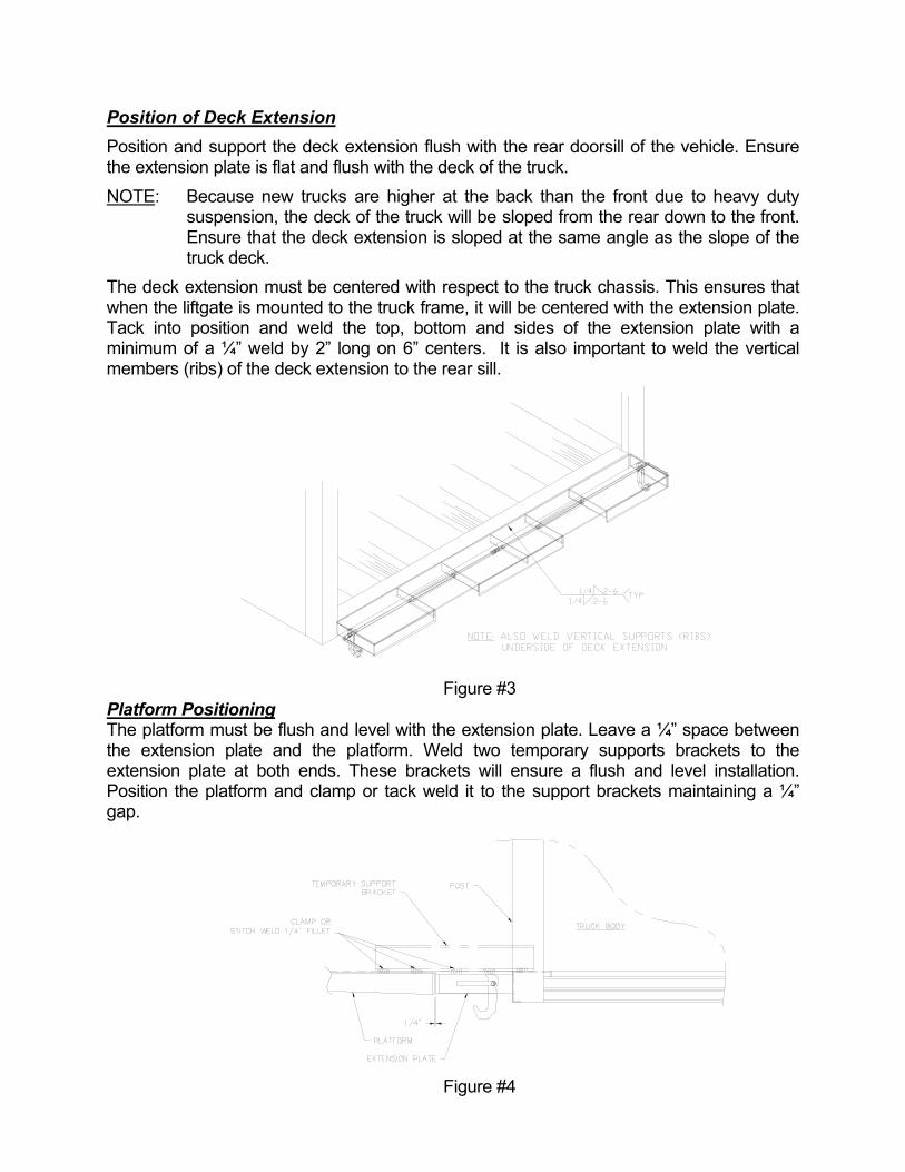
Position of Deck Extension Position and support the deck extension flush with the rear doorsill of the vehicle. Ensure the extension plate is flat and flush with the deck of the truck. NOTE: Because new trucks are higher at the back than the front due to heavy duty
suspension, the deck of the truck will be sloped from the rear down to the front. Ensure that the deck extension is sloped at the same angle as the slope of the truck deck.
The deck extension must be centered with respect to the truck chassis. This ensures that when the liftgate is mounted to the truck frame, it will be centered with the extension plate. Tack into position and weld the top, bottom and sides of the extension plate with a minimum of a ¼” weld by 2” long on 6” centers. It is also important to weld the vertical members (ribs) of the deck extension to the rear sill.
Figure #3
Platform Positioning The platform must be flush and level with the extension plate. Leave a ¼” space between the extension plate and the platform. Weld two temporary supports brackets to the extension plate at both ends. These brackets will ensure a flush and level installation. Position the platform and clamp or tack weld it to the support brackets maintaining a ¼” gap.
Figure #4

Platform Adjusting Bolts There are two adjusting bolts on the platform under the pivot lugs. These bolts are adjusted at the factory to ensure a square and level installation. Once the platform is clamped to the temporary braces, the mainframe should automatically be in the correct position for installation. If the mainframe tube is not parallel with the truck from the front frame to the back and / or side to side, thread the adjusting bolts in or out until the mainframe tube is leveled.
Figure #5
Mainframe Positioning The mainframe should be in the correct position. Check that the top of the main tube is approximately 25 ½” down from the top of the deck extension. If the mainframe is not level or parallel to the deck extension then the main frame should be adjusted using the adjusting bolts. Once satisfied with the mainframe positioning, weld the liftgate attaching plates to the main frame and to the truck frame. Welds must be minimum of ¼” fillet weld on front and back of each attaching plate. Be sure to weld the attaching plates to the truck body’s long sill as well.
Figure #6

Pivot Lug Stops Once the mainframe is welded into place, the pivot lug stops can be cut off.
Figure #7
Pump Installation Remove the breather cap from the reservoir and insert the reservoir through the large hole in the pump box. Set the pump box on the mainframe bracket. Ensure that the reservoir tank is to the curbside of the truck, this means that the opening of the pump box is to the front of the truck. Using the fasteners supplied in the installation kit, fasten the pump box and pump to the bracket on the mainframe. Fill the reservoir with DEXTRON III automatic transmission fluid, and replace the breather cap. Optional Side Mount Pump Box With the side mounted pump box the solenoids are pre-installed and wired inside the pump box. Locate the pump box behind the curbside mud flap under the body approximately 4 feet from the back of the truck, and 6 inches in from the outside. Weld the pump box in position with the door facing the curbside. Fill the reservoir with DEXTRON III automatic transmission fluid, and replace the breather cap.
Figure #8

Hose Installation Packaged with your liftgate you will find both long and short hose assemblies, two 90º elbows (-6 ORB,1/4”FNPT), four 90º elbows (-6 ORB,- 4JIC), two flow control valves (1.0 gpm), two adapters and two swivel tee’s. Install two of the 90º elbows (-6 0RB,-4 JIC) to the pump ports marked C1 and C2. Connect the other two 90º elbows (-6 ORB, -4 JIC) to the cylinder ports at the rod end, and the 90ºelbows (-6ORB, ¼ FNPT) to the cylinder ports at the base end. Attach the flow control valve and adapter to the elbow at the base end of the cylinder. Connect the female end of the swivel tees to the elbows on the pump. Attach the short hoses to the swivel tee from port C1. Route the C1 hoses to the base end of the cylinders. Attach the long hoses to the swivel tee from port C2. Route the C2 hoses to the rod end of the cylinder. Ensure that the installed hoses do not interfere with moving or hot parts. Also ensure that the hoses do not stretch or kink while the liftgate is in operation. Check to see that there is a number “1.0” stamped on the flow control valve, this is for all twin cylinder models. This will restrict the flow to 1.0 GPM per cylinder.
Figure #9
Figure #10

Hose Installation (Side Mounted Pump Box) The hose installation for a side mounted pump box is the same as the mainframe-mounted pumps except the pump is pre-installed in the pump box. You will also be supplied with one bulkhead plate and two-bulkhead tees. Weld the bulkhead plate to the mainframe tube, and attach the bulkhead tees to the plates. Route the 60-inch hoses from the bulkhead adapters already on the rear face of the pump box to the bulkhead tee’s. Then route the 50 and 60-inch hoses to the cylinders as specified previously.
Battery Hook up Run the battery cable from the solenoid (see solenoid wiring hook-up) to the master disconnect switch. The master disconnect switch should be mounted in the cab of the truck on the floor beside the drivers seat. Cut the cable to length and attach it to the master disconnect switch. Then run the cable from master disconnect switch to the positive side of the battery. NOTE: Be sure that the trucks electrical system is disconnected before
attempting to hook up the electrical components of the liftgate. NOTE: Holland recommends that dielectric grease be applied to all exposed
electrical terminals. Corroded terminals are not covered under the Holland standard warranty.
Optional Circuit Breaker The optional 150amp circuit breaker is installed as close to the battery as possible. The battery hook up is the same except the cable from the master disconnect switch now goes to the circuit breaker and then to the battery.
Figure #11
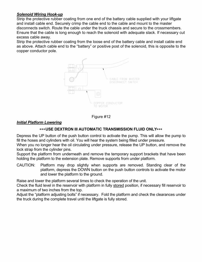
Solenoid Wiring Hook-up Strip the protective rubber coating from one end of the battery cable supplied with your liftgate and install cable end. Securely crimp the cable end to the cable and mount to the master disconnects switch. Route the cable under the truck chassis and secure to the crossmembers. Ensure that the cable is long enough to reach the solenoid with adequate slack. If necessary cut excess cable away. Strip the protective rubber coating from the loose end of the battery cable and install cable end as above. Attach cable end to the “battery” or positive post of the solenoid, this is opposite to the copper conductor pole.
Figure #12 Initial Platform Lowering
∗∗∗USE DEXTRON III AUTOMATIC TRANSMISSION FLUID ONLY∗∗∗ Depress the UP button of the push button control to activate the pump. This will allow the pump to fill the hoses and cylinders with oil. You will hear the system being filled under pressure. When you no longer hear the oil circulating under pressure, release the UP button, and remove the lock strap from the cylinder pins. Support the platform from underneath and remove the temporary support brackets that have been holding the platform to the extension plate. Remove supports from under platform. CAUTION: Platform may drop slightly when supports are removed. Standing clear of the
platform, depress the DOWN button on the push button controls to activate the motor and lower the platform to the ground.
Raise and lower the platform several times to check the operation of the unit. Check the fluid level in the reservoir with platform in fully stored position, if necessary fill reservoir to a maximum of two inches from the top. Adjust the “platform adjusting bolts” if necessary. Fold the platform and check the clearances under the truck during the complete travel until the liftgate is fully stored.

Return Spring Installation Find the springs in the loose parts bag. Install the two extensions springs from the washer that is welded to the latch hook, and to the washer welded on the underside of the extension plate. One spring per side.
Figure #13 Latch Pin Installation Always disconnect the vehicles electrical system before welding. Once the installers have satisfied themselves that the installation is proper, sound and safe, the liftgate is to be fitted with two latch pins for safety in the storage position. NOTE: The mechanism is designed so that the latches prevent uncontrolled lowering of the liftgate
from the folded position in the event of a hydraulic leak. While in the folded position, the arms should contact the rear sill of the body. It may be necessary to add blocks or notch the sill so that the platform contacts the sill and not the extension plate. With the liftgate in the folded position, locate the 1” diameter pins. Ensure that the latch is vertical, or 90°, and place the pin in the crotch of the latch. Tack the pins into place. Check the operation to be sure that the latches engage and disengage with the pins freely. The latches must move freely when rotating the handle. Lower the liftgate to the ground and weld pins all around 100% to the platform side plates.
Figure #14

Step Assembly Installation The steps are located so that the top of the upright is flush with the top of the extension plate. Weld steps to the extension plate and rear doorsill wherever possible. Ensure that the step assemblies are straight and square so they don’t affect the overall width of the truck or obstruct the operation of the liftgate.
Optional Step Braces Holland Equipment Limited recommends that step braces be installed. The braces must be secured to the step assemblies and to the mainframe of the liftgate.
Figure #15
Donut Opener Assembly Installation (XA-50935) With the liftgate in stored position, lower the platform and position the opener under the step so it contacts the tip of the folded flip-over. The position of the donut opener may vary from installation to installation and from model to model. Tack the opener into position and check the operation of the liftgate. Once satisfied weld into position with minimum ¼” welds and repeat these steps for the other side.
Figure #16
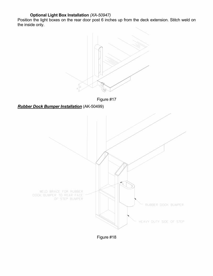
Optional Light Box Installation (XA-50947) Position the light boxes on the rear door post 6 inches up from the deck extension. Stitch weld on the inside only.
Figure #17
Rubber Dock Bumper Installation (AK-50499)
Figure #18

Optional Anti-Bounce Installation (AK-57033) Raise the folded liftgate to within two inches of being stored. Position anti-bounce bumper into place as shown below and weld angle into place.
NOTE: Only one assembly per liftgate is required.
Figure #19

ACCESSORY KITS INSTALLATION KIT – AK-57021
DESCRIPTION PART NUMBER QUANTITY
LATCH PIN x 1.75” LG. XB-50003 2
HEX BOLT, FLANGED LOCKING, 3/8-16 x 3/4” LG. XF-08-038C5-075P 2
CABLE END, 1/2” XB-50037-500 2
CABLE END, 5/16” XB-50037-312 1
LATCH SPRING, 3” LG. XB-50040 2
INSTALLATION KIT – RK-50401-R (SIDE MOUNT PUMP BOX)
DESCRIPTION PART NUMBER QUANTITY
LATCH PIN x 1.75” LG. XB-50003 2
CABLE END, 1/2” XB-50037-500 1
CABLE END, 5/16” XB-50037-312 1
LATCH SPRING, 3” LG. XB-50040 2
DECAL KIT - RK-57033
DESCRIPTION PART NUMBER QUANTITY
CAUTION - “MAX. CAPACITY” XB-51913 2
CAUTION - “STAND CLEAR” XB-50344 1
“OPERATING INSTRUCTIONS” XB-50345 1
“READ AND UNDERSTAND” XB-50346 1
French-“MAX. CAPACITY” XB-51914 2
French-“STAND CLEAR” XB-50349 1
French-“OPERATING INSTRUCTIONS” XB-50352 1
French-“READ AND UNDERSTAND” XB-50353 1
WARNING – “SAFETY LATCHES” XB-50528 2
WARNING – “HIGH PRESSURE” XB-54995 1
French – “HIGH PRESSURE” XB-64388 1
DANGER – “Pinch point” XB-51170 2

INSTALLATION KITS
AK-50495: Tractor Jumper Kit ITEM# PART# DESCRIPTION QTY
1 XB-50038-40 2 ga. BATTERY CABLE 40ft.2 XB-50118 MALE CONNECTOR PLUG 13 XB-50037 CABLE END 2
Notes: 1) 40ft battery cable is supplied 2) Cut cable to desired length for both lines.
AK-50497: Trailer Installation Kit Powered by tractor battery
ITEM# PART# DESCRIPTION QTY1 XB-50116 FEMALE SOCKET 12 XB-50038-40 2 ga. BATTERY CABLE 40ft3 XB-50117 BUTT CONNECTOR 1
Note: 1) 40ft battery cable already supplied with liftgate. 2) Install cable supplied with liftgate kit to cable with this kit using the butt connector provided.
) Ensure that there is proper ground between the female socket and the tailgate.
AK-50496: Trailer Installation Kit Powered by battery on trailer, charged from tractor battery.
ITEM# PART# DESCRIPTION QTY
1 XB-50038-40 2 ga. BATTERY CABLE 40ft2 XB-50116 FEMALE SOCKET 13 TRDA769217 TERMINAL 14 TRDA762614 GROUND STRAP - 9" 15 XB-50124 BATTERY BOX 16 XB-50126 BATTERY TRAY 1
Notes: 1) Battery not supplied

PLACEMENT FOR DECAL KIT (RK-57033) Important: These decals must be installed, maintained, and kept visible and legible. Failure to do so could result in operation without the benefit of the important information they contain leading to unsafe conditions or damage to the liftgate. In either case Holland Equipment will not be liable and warranty becomes void.
Item #1 – 2 req’d (XB-50344) 2 tailgate
Item #2 – 4 req’d (XB-51913) 1 left side 1 right side 2 tailgate
Item #7 – 2 req’d (XB-51170) Item #5 – 2 req’d (XB-50528) 1 left side 1 left side 1 right side 1 right side
Item #3 – 2 req’d (XB-50346) Item #4 – 2 req’d (XB-50345) Item #6 – 2 req’d (XB-54995) 1 left side 1 left side 1 left side 1 right side 1 right side 1 right side

PREVENTATIVE MAINTENANCE 1.0 DAILY • Before use, inspect the liftgate for damage to mounting assemblies, mechanical parts, and hydraulic
components and hoses. Any noticeable defects must be repaired prior to operation to avoid damage and possible injury.
2.0 MONTHLY MAINTENANCE • Every 1000 cycles or 30 days (which ever occurs first) all pivot points should be lubricated using EP2
chassis grease. In severe winter conditions it may be necessary to lubricate more frequently. • Lubricate linkage pivot points with WD40 or light engine oil. • Check oil level in reservoir. 3.0 YEARLY MAINTENANCE • Once a year change the oil and oil filter. When filling pump reservoir use a funnel with a fine mesh
screen. Use Dextron III transmission fluid. • Inspect all decals and replace any that are not clearly visible or legible. 4.0 BI-YEARLY MAINTENANCE • Every 24,000 cycles or 2 years (which ever occurs first) disassemble the liftgate and inspect all pivot
points for wear, replace any pins or part that show signs of wear. • Replace seal kit in cylinder, also replace any worn hydraulic hoses. • Undercoat all crossmembers by removing plugs in crossmembers, spray undercoat inside and
replace plugs.

TROUBLE SHOOTING
FAULT CAUSE REMEDY 1. Insufficient lubrication Lubricate all pivot points 2. Undue wear of mechanical
components causing binding Check freedom of all moving parts
3. Incorrect or contaminated oil in system
Oil should be clean Dextron III Automatic Trans. Oil
4. Restricted hydraulic hose Check hoses for external damage or pinching
5. Blocked hydraulic hose Check for blockages in hoses 6. Battery flat, not enough voltage to
solenoid Re-charge or replace battery
7. Electrical connections corroded or disconnected
Check connections
Platform lowers slowly or will not lower
8. Mechanical components seized or damaged
Lubricate all pivot points and replace all damaged items
Platform is tilted Incorrect platform adjustment. Incorrect installation
Adjust leveling bolts. Remove and reinstall according to directions
1. Relief valve setting too low Adjust relief valve setting 2. Hydraulic pump worn Change worn parts or entire pump 3. Hydraulic cylinder leaking internally Replace seals or complete cylinder
Unit will not lift capacity load
4. Hydraulic system not plumbed properly
Check to see that the hose connected to the C1 port (high pressure) is plumbed to the rod end of the cylinder
1. Flow control valve blocked Replace valve Platform descends too slow with load 2. Flow control incorrectly installed Check location and direction of arrow
on valve 1. Too much oil in reservoir Ensure level of oil allows displacement
of rods 2. Wrong flow control fitting Check that the number stamped on
flow control fitting is opposite to the number of cylinders on your tailgate.
Oil expels from reservoir when lowering
3. Motor is not running when lowering platform
Check for faulty down button on push button control box
1. battery flat Re-charge or replace battery 2. (Tractor / Trailer vehicles only)
Electrical coupling to trailer not complete
Connect coupling
3. Electrical wiring to pump broken or corroded
Check wiring to pump
4. Remote control switch broken or shorted
Check wiring to control switch
Pump will not operate
5. Solenoid switch on pump faulty Check solenoid switch 1. Latches binding on lock pins Move handle to raise position to lift
gate to clear latches, then lower. 2. Linkage broken or disconnected Repair linkage
Control handle won’t operate to lower gate from folded position
3. Linkage won’t move freely Lubricate linkage, repair broken or seized parts or check for interference between linkage and rear sill of tailgate.

TROUBLE SHOOTING
FAULT CAUSE REMEDY 1. Battery flat Re-charge or replace battery 2. Voltage too low Check voltage 3. Insufficient oil in reservoir With platform on ground, fill tank to
within 2” of top with Dextron III Transmission fluid
Platform will not raise
4. Pump solenoid switch burned out Replace pump solenoid switch 1. liftgate is loaded past rated capacity Reduce the load on the platform 2. Hose or fitting leak Check and retorque fittings 3. Leaking check valve or relief valve Clean or replace valve 4. Broken pump shaft Replace shaft or coupling as
necessary 5. Pivot points seized Lubricate 6. worn or scored piston Replace cylinder 7. Worn piston seals Replace seals
Motor runs but will not raise platform
8. Pump is worn out Replace pump 1. Insufficient oil in reservoir Fill reservoir 2. Air lock in hydraulic system Operate raise control for a few
seconds at top of stroke. Repeat two times pausing between operations
Platform will not raise smoothly
3. Undue mechanical wear or lack of lubrication
Lubricate pivots, replace worn parts
1. Cylinder seal leak Replace seals or cylinder if scored Platform creeps down when stationary 2. Dirt under check valve Clean valve
1. Battery flat Recharge battery 2. liftgate is loaded past rated capacity Reduce the load on the platform 2. Faulty cable connections. Electrical
connections corroded or disconnected
Check connections
3. Pump motor not grounded adequately
Check grounding to truck frame
4. Hose leaking Tighten or replace hoses 5. Cylinder internal leak Replace seals or replace cylinder 6. Lack of lubrication or undue
mechanical wear Lubricate all pivot points, replace worn parts
7. Incorrect relief valve setting Check relief valve setting
Platform raises slowly
8. Worn pump or clogged filter. Check pump and filter Platform tips up when being lowered to the ground
The lifting mechanisms are worn due to either severe wear or an overload situation
Requires a rebuild. Replace parallel arms, shackles, pins, and possibly the lift frame.