tld, sterotactic & periscopic systems - rpdinc.com · variations in annealing temperature will...
TRANSCRIPT
TLD, STEREOTTLD, STEREOTACTIC & PERISCOPIC SYSTEMS ACTIC & PERISCOPIC SYSTEMS
X - 1
X
Radiation Products Design, Inc. l Albertville, MN 55301 l (800) 497-2071 l Fax: (763) 497-2295 l www.rpdinc.com
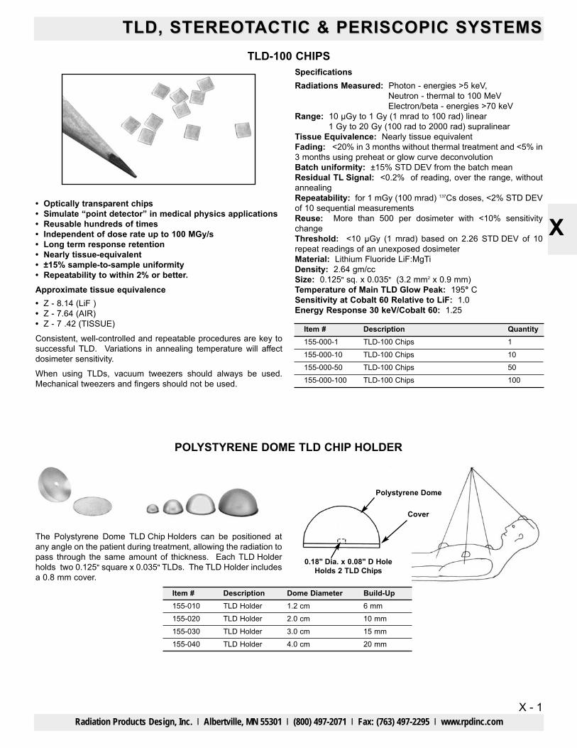
TLD-100 CHIPS
• Optically transparent chips• Simulate “point detector” in medical physics applications• Reusable hundreds of times• Independent of dose rate up to 100 MGy/s• Long term response retention• Nearly tissue-equivalent• ±15% sample-to-sample uniformity• Repeatability to within 2% or better.Approximate tissue equivalence• Z - 8.14 (LiF )• Z - 7.64 (AIR)• Z - 7 .42 (TISSUE)
Consistent, well-controlled and repeatable procedures are key tosuccessful TLD. Variations in annealing temperature will affectdosimeter sensitivity.
When using TLDs, vacuum tweezers should always be used.Mechanical tweezers and fingers should not be used.
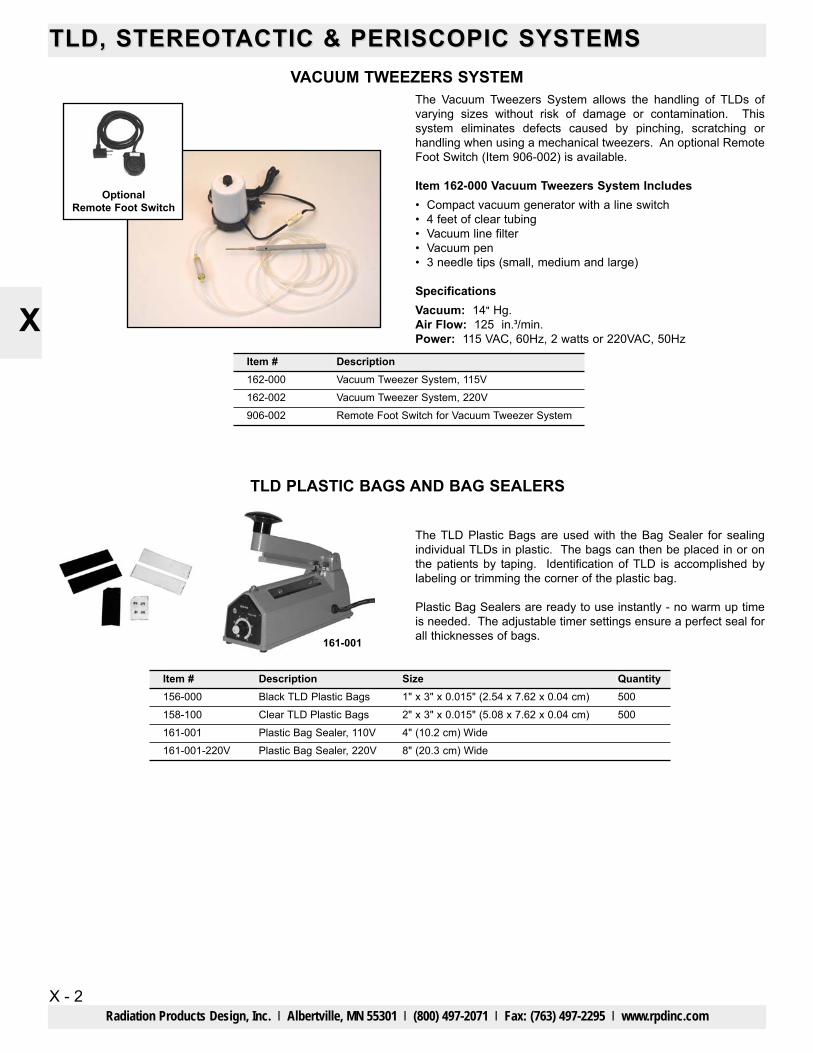
Polystyrene Dome
0.18" Dia. x 0.08" D HoleHolds 2 TLD Chips
POLYSTYRENE DOME TLD CHIP HOLDER
The Polystyrene Dome TLD Chip Holders can be positioned atany angle on the patient during treatment, allowing the radiation topass through the same amount of thickness. Each TLD Holderholds two 0.125" square x 0.035" TLDs. The TLD Holder includesa 0.8 mm cover.
SpecificationsRadiations Measured: Photon - energies >5 keV,
Neutron - thermal to 100 MeVElectron/beta - energies >70 keV
Range: 10 μGy to 1 Gy (1 mrad to 100 rad) linear 1 Gy to 20 Gy (100 rad to 2000 rad) supralinear
Tissue Equivalence: Nearly tissue equivalentFading: <20% in 3 months without thermal treatment and <5% in3 months using preheat or glow curve deconvolutionBatch uniformity: ±15% STD DEV from the batch meanResidual TL Signal: <0.2% of reading, over the range, withoutannealingRepeatability: for 1 mGy (100 mrad) 137Cs doses, <2% STD DEVof 10 sequential measurementsReuse: More than 500 per dosimeter with <10% sensitivitychangeThreshold: <10 μGy (1 mrad) based on 2.26 STD DEV of 10repeat readings of an unexposed dosimeterMaterial: Lithium Fluoride LiF:MgTiDensity: 2.64 gm/ccSize: 0.125" sq. x 0.035" (3.2 mm2 x 0.9 mm)Temperature of Main TLD Glow Peak: 195° CSensitivity at Cobalt 60 Relative to LiF: 1.0Energy Response 30 keV/Cobalt 60: 1.25
Cover
Item #155-010155-020155-030155-040
DescriptionTLD Holder
Dome Diameter1.2 cm2.0 cm3.0 cm4.0 cm
Build-Up6 mm10 mm15 mm20 mm
TLD HolderTLD HolderTLD Holder
Item #155-000-1
155-000-50 155-000-100
Description QuantityTLD-100 Chips 1
TLD-100 Chips 50TLD-100 Chips 100
155-000-10 TLD-100 Chips 10
TLD, STEREOTTLD, STEREOTACTIC & PERISCOPIC SYSTEMSACTIC & PERISCOPIC SYSTEMS
X - 2
X
Radiation Products Design, Inc. l Albertville, MN 55301 l (800) 497-2071 l Fax: (763) 497-2295 l www.rpdinc.com
VACUUM TWEEZERS SYSTEMThe Vacuum Tweezers System allows the handling of TLDs ofvarying sizes without risk of damage or contamination. Thissystem eliminates defects caused by pinching, scratching orhandling when using a mechanical tweezers. An optional RemoteFoot Switch (Item 906-002) is available.
Item 162-000 Vacuum Tweezers System Includes• Compact vacuum generator with a line switch• 4 feet of clear tubing• Vacuum line filter• Vacuum pen• 3 needle tips (small, medium and large)
SpecificationsVacuum: 14" Hg.Air Flow: 125 in.3/min.Power: 115 VAC, 60Hz, 2 watts or 220VAC, 50Hz
TLD PLASTIC BAGS AND BAG SEALERS
The TLD Plastic Bags are used with the Bag Sealer for sealingindividual TLDs in plastic. The bags can then be placed in or onthe patients by taping. Identification of TLD is accomplished bylabeling or trimming the corner of the plastic bag.
Plastic Bag Sealers are ready to use instantly - no warm up timeis needed. The adjustable timer settings ensure a perfect seal forall thicknesses of bags.161-001
OptionalRemote Foot Switch
Item #156-000158-100161-001
Description QuantityBlack TLD Plastic Bags 500Clear TLD Plastic Bags 500Plastic Bag Sealer, 110V
Size1" x 3" x 0.015" (2.54 x 7.62 x 0.04 cm)2" x 3" x 0.015" (5.08 x 7.62 x 0.04 cm)4" (10.2 cm) Wide
161-001-220V Plastic Bag Sealer, 220V 8" (20.3 cm) Wide
Item #162-000
906-002
DescriptionVacuum Tweezer System, 115V
Remote Foot Switch for Vacuum Tweezer System162-002 Vacuum Tweezer System, 220V
TLD, STEREOTTLD, STEREOTACTIC & PERISCOPIC SYSTEMS ACTIC & PERISCOPIC SYSTEMS
X - 3
X
Radiation Products Design, Inc. l Albertville, MN 55301 l (800) 497-2071 l Fax: (763) 497-2295 l www.rpdinc.com
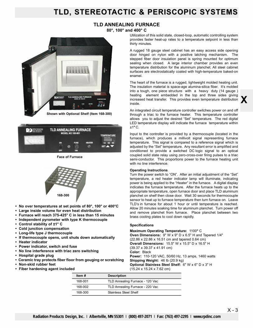
TLD ANNEALING FURNACE80°, 100° and 400° C
• No over temperatures at set points of 80°, 100° or 400°C• Large inside volume for even heat distribution• Furnace will reach 375-425° C in less than 15 minutes• Independent pyrometer with type K thermocouple• Control stability of ±1° C• Cold junction compensation• Long-life type J thermocouple• If thermocouple opens, unit shuts down automatically• Heater indicator• Power indicator, switch and fuse• No line interference with triac zero switching• Hospital grade plug • Ceramic tray protects fiber floor from gouging or scratching• Non-skid rubber feet• Fiber hardening agent included
Utilization of this solid state, closed-loop, automatic controlling systemprovides faster heat-up rates to a temperature setpoint in less thanthirty minutes.
A rugged 18 gauge steel cabinet has an easy access side openingdoor hinged on nylon with a positive latching mechanism. Thestepped fiber door insulation panel is spring mounted for optimumsealing when closed. A large interior chamber provides an eventemperature distribution for the aluminum planchet. All steel cabinetsurfaces are electrostatically coated with high-temperature baked-onenamel.
The heart of the furnace is a rugged, lightweight molded heating unit.The insulation material is space-age alumina-silica fiber. It’s moldedinto a tough, one piece structure with a heavy duty (14 gauge )heating element embedded in the top and three sides givingincreased heat transfer. This provides even temperature distributioninside.
An integrated circuit temperature controller switches power on and offthrough a triac to the furnace heater. This temperature controllerallows you to adjust the desired “Set” temperature. The red digitalLED temperature display will indicate the furnace temperature within±1° C.
Input to the controller is provided by a thermocouple (located in thefurnace), which produces a millivolt signal representing furnacetemperature. This signal is compared to a reference signal which isadjusted by the “Set” temperature. Any resultant error is amplified andconditioned to provide a switched DC logic signal to an opticalcoupled solid state relay using zero-cross-over firing pulses to a triacsemi-conductor. This proportions power to the furnace heating unitwith no line interference.
Operating InstructionsTurn the power switch to “ON”. After an initial adjustment of the “Set”temperature, a red heater indicator lamp will illuminate, indicatingpower is being applied to the “Heater” in the furnace. A digital displayindicates the furnace temperature. After the furnace heats up to theappropriate temperature, open furnace door and place TLD aluminumplanchet on shelf then close door. Wait 30 seconds for thermocouplesensor to heat up to furnace temperature then turn furnace on. LeaveTLD’s in furnace for about 1 hour or until temperature is reached.Allow 20 minutes soaking time for aluminum planchet. Turn power offand remove planchet from furnace. Place planchet between twobrass cooling plates to cool down rapidly.
SpecificationsMaximum Operating Temperature: 1100° COven Dimensions: 9" W x 9" D x 6.5" H and Tapered 1/4"(22.86 x 22.86 x 16.51 cm and tapered 0.64 cm)Overall Dimensions: 15.5" W x 15.5" D x 16.5" H(39.37 x 39.37 x 41.91 cm)Color: BlackPower: 110-120 VAC, 50/60 Hz, 13 amps, 1460 wattsShipping Weight: 46 lb (20.9 kg)Optional Stainless Steel Shelf: 6" W x 6" D x 3" H(15.24 x 15.24 x 7.62 cm)
168-300
Shown with Optional Shelf (Item 168-300)
Item #168-001168-002168-300
DescriptionTLD Annealing Furnace - 120 VacTLD Annealing Furnace - 220 VacStainless Steel Shelf
Face of Furnace
TLD, STEREOTTLD, STEREOTACTIC & PERISCOPIC SYSTEMSACTIC & PERISCOPIC SYSTEMS
X - 4
X
Radiation Products Design, Inc. l Albertville, MN 55301 l (800) 497-2071 l Fax: (763) 497-2295 l www.rpdinc.com
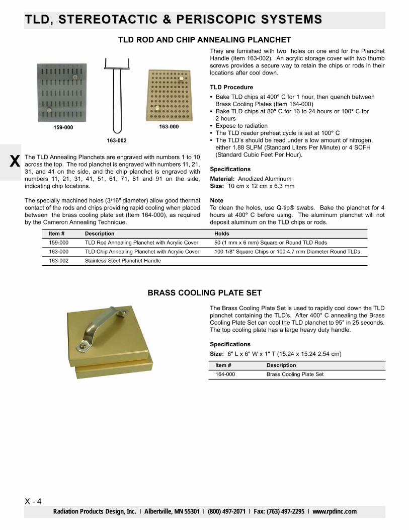
TLD ROD AND CHIP ANNEALING PLANCHETThey are furnished with two holes on one end for the PlanchetHandle (Item 163-002). An acrylic storage cover with two thumbscrews provides a secure way to retain the chips or rods in theirlocations after cool down.
TLD Procedure• Bake TLD chips at 400° C for 1 hour, then quench between
Brass Cooling Plates (Item 164-000)• Bake TLD chips at 80° C for 16 to 24 hours or 100° C for
2 hours• Expose to radiation• The TLD reader preheat cycle is set at 100° C• The TLD’s should be read under a low amount of nitrogen,
either 1.88 SLPM (Standard Liters Per Minute) or 4 SCFH(Standard Cubic Feet Per Hour).
SpecificationsMaterial: Anodized AluminumSize: 10 cm x 12 cm x 6.3 mm
NoteTo clean the holes, use Q-tip® swabs. Bake the planchet for 4hours at 400° C before using. The aluminum planchet will notdeposit aluminum on the TLD chips or rods.
Item #159-000163-000163-002
DescriptionTLD Rod Annealing Planchet with Acrylic CoverTLD Chip Annealing Planchet with Acrylic CoverStainless Steel Planchet Handle
Holds50 (1 mm x 6 mm) Square or Round TLD Rods100 1/8" Square Chips or 100 4.7 mm Diameter Round TLDs
159-000
163-002
163-000
The TLD Annealing Planchets are engraved with numbers 1 to 10across the top. The rod planchet is engraved with numbers 11, 21,31, and 41 on the side, and the chip planchet is engraved withnumbers 11, 21, 31, 41, 51, 61, 71, 81 and 91 on the side,indicating chip locations.
The specially machined holes (3/16" diameter) allow good thermalcontact of the rods and chips providing rapid cooling when placedbetween the brass cooling plate set (Item 164-000), as requiredby the Cameron Annealing Technique.
BRASS COOLING PLATE SET
The Brass Cooling Plate Set is used to rapidly cool down the TLDplanchet containing the TLD’s. After 400° C annealing the BrassCooling Plate Set can cool the TLD planchet to 95° in 25 seconds.The top cooling plate has a large heavy duty handle.
SpecificationsSize: 6" L x 6" W x 1" T (15.24 x 15.24 2.54 cm)
Item #164-000
DescriptionBrass Cooling Plate Set
TLD, STEREOTTLD, STEREOTACTIC & PERISCOPIC SYSTEMS ACTIC & PERISCOPIC SYSTEMS
X - 5
X
Radiation Products Design, Inc. l Albertville, MN 55301 l (800) 497-2071 l Fax: (763) 497-2295 l www.rpdinc.com
TLD IRRADIATION PHANTOMS
The TLD Polystyrene Irradiation Phantom consists of 2 plates. TheTLD phantom is numbered 10 to to 1 across the top. The left sideof the TLD phantom is numbered 11 to 91 for TLD chips or 11 to41 for TLD rods. This numbering matches the annealing planchetwhen the irradiation phantom is flipped. The area that holds thechips or rods is 8.5 cm x 10.5 cm centered on the polystyreneplate.
The 6 mm polystyrene cover is secured to the bottom plate whichholds TLDs in the individual holes. The plates can be separatedfor easy cleaning.
SpecificationsSize: 1.43 cm x 25 cm sq. (9/16" x 9.8" sq)
The Plastic or Solid Water TLD irradiation phantoms consist of a5 mm phantom plate and a 1/4" acrylic cover. These arenumbered the same as the Polystyrene Irradiation Phantom andwill hold 100 TLD chips or 50 TLD Rods.
SpecificationsSize: 5 mm x 30 cm sq.
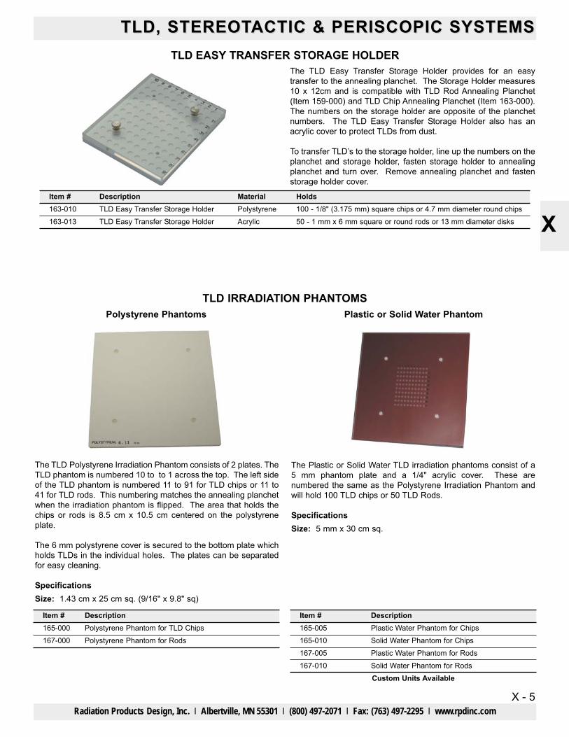
TLD EASY TRANSFER STORAGE HOLDERThe TLD Easy Transfer Storage Holder provides for an easytransfer to the annealing planchet. The Storage Holder measures10 x 12cm and is compatible with TLD Rod Annealing Planchet(Item 159-000) and TLD Chip Annealing Planchet (Item 163-000).The numbers on the storage holder are opposite of the planchetnumbers. The TLD Easy Transfer Storage Holder also has anacrylic cover to protect TLDs from dust.
To transfer TLD’s to the storage holder, line up the numbers on theplanchet and storage holder, fasten storage holder to annealingplanchet and turn over. Remove annealing planchet and fastenstorage holder cover.
Plastic or Solid Water PhantomPolystyrene Phantoms
Item #165-000 167-000
DescriptionPolystyrene Phantom for TLD ChipsPolystyrene Phantom for Rods
Custom Units Available
Item #165-005165-010167-005167-010
DescriptionPlastic Water Phantom for ChipsSolid Water Phantom for ChipsPlastic Water Phantom for RodsSolid Water Phantom for Rods
Item #163-010 163-013
DescriptionTLD Easy Transfer Storage HolderTLD Easy Transfer Storage Holder
MaterialPolystyreneAcrylic
Holds100 - 1/8" (3.175 mm) square chips or 4.7 mm diameter round chips50 - 1 mm x 6 mm square or round rods or 13 mm diameter disks

TLD, STEREOTTLD, STEREOTACTIC & PERISCOPIC SYSTEMSACTIC & PERISCOPIC SYSTEMS
X - 6
X
Radiation Products Design, Inc. l Albertville, MN 55301 l (800) 497-2071 l Fax: (763) 497-2295 l www.rpdinc.com
STEREOTACTIC COLLIMATOR SYSTEM
Stereotactic Collimator System Includes• Tray• Translation Stage Tray• Barrel
When placing an order, please provide the following information:• Item 1080-• Machine• Machine Type• Target to Bottom of Wedge Tray Slot in centimeters• Target to End of Collimator Barrel in centimeters• Contact Information
The contact person will have to verify all information prior tomanufacturing.
1080-08
LEAD COLLIMATORS
The lead collimators have a lip at the bottom which fits into the barrelto insure proper placement of the lead collimator.
The lead collimators are custom designed for each machine based onfield size, flatness, and the slope angle of the radiation penumbraedge.
1080-20with long barrel
1081-73
Item #1080-201080-211080-301080-321080-061080-081081-73
DescriptionVarian Type II, Screw Coded with X-Y Stage, Wedge SlotVarian Type III, Digital Coded with X-Y Stage, Wedge SlotSiemens Screw Coded with X-Y Stage, Wedge SlotSiemens Digital Coded with X-Y Stage, Wedge SlotX-Y Pointer SystemStereotactic Front PointerStereotactic Film Holder
Other Manufacturers AvailableItems are Custom Made and Nonreturnable
The Stereotactic Collimator System is custom made for eachcustomer. The customer must select the options wanted.
The tray is made to be placed in the wedge tray slot. An X-Ytranslation stage tray allows for adjustment of the collimator barrel inthe X-Y directions. The collimator barrel attaches to either the wedgetray or the X-Y translation stage tray.
The collimator barrel has an outside diameter of 7 cm with an insidediameter of 6.3 cm. The length of the barrel is specified by thecustomer. With short collimator barrels the lead collimators insert fromthe top of the barrel (the barrel unscrews from the tray). Longcollimator barrels have a screw on bottom which is taken off to insertthe lead collimator from the bottom. A test collimator will be sent todetermine divergence prior to manufacturing.
Optional AccessoriesX-Y pointer system (Item 1080-06), or a stereotactic front pointer (Item1080-08). The stereotactic front pointer has a magnetic base that willattach to the collimator barrel or Item 1081-73 Stereotactic FilmHolder.
The Stereotactic Film Holder has a ring clamp that mounts to thecollimator barrel of the Stereotactic Collimator System. The removablerod extends past isocenter. A film holder plate slides onto the rod andis adjustable to the proper distance, a tightening screw will hold thefilm holder plate in place. Two spring clips on the film holder plateholds the film.
1080-21with short barrel
Item #1081-05
1081-101081-151081-201081-251081-301081-351081-40
Stereotactic Lead CollimatorDiameter at Isocenter 5 mm
Diameter at Isocenter 10 mmDiameter at Isocenter 15 mmDiameter at Isocenter 20 mmDiameter at Isocenter 25 mmDiameter at Isocenter 30 mmDiameter at Isocenter 35 mmDiameter at Isocenter 40 mm
Items are Custom Made and Nonreturnable
1081-08 Diameter at Isocenter 8 mm
TLD, STEREOTTLD, STEREOTACTIC & PERISCOPIC SYSTEMS ACTIC & PERISCOPIC SYSTEMS
X - 7
X
Radiation Products Design, Inc. l Albertville, MN 55301 l (800) 497-2071 l Fax: (763) 497-2295 l www.rpdinc.com
STEREOTACTIC ADAPTER FOR VARIAN TO RADIONICS SRS HEAD FRAME
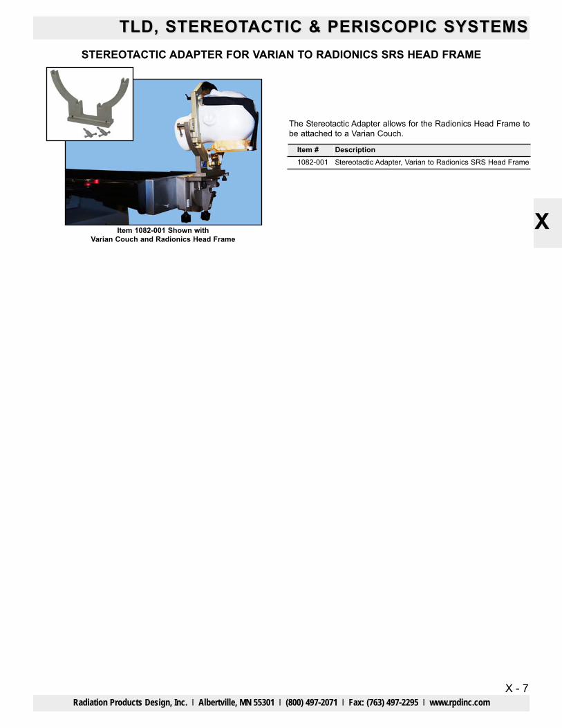
The Stereotactic Adapter allows for the Radionics Head Frame tobe attached to a Varian Couch.
Item #1082-001
DescriptionStereotactic Adapter, Varian to Radionics SRS Head Frame
Item 1082-001 Shown withVarian Couch and Radionics Head Frame
TLD, STEREOTTLD, STEREOTACTIC & PERISCOPIC SYSTEMSACTIC & PERISCOPIC SYSTEMS
X - 8
X
Radiation Products Design, Inc. l Albertville, MN 55301 l (800) 497-2071 l Fax: (763) 497-2295 l www.rpdinc.com
MRI DISTORTION PHANTOM FOR SRSFor Assessment of Image Distortion in Treatment Planning Systems
• Provides a realistic anthropomorphic scenario for CT andMR imaging
• Unique inter-cranial 3D grid design allows assessment ofspatial distortion
• Special pads enable use with all fixation frames• CT/MR markers facilitate positioning and image registration
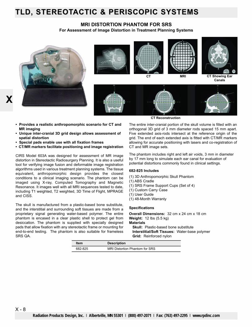
CIRS Model 603A was designed for assessment of MR imagedistortion in Stereotactic Radiosurgery Planning. It is also a usefultool for verifying image fusion and deformable image registrationalgorithms used in various treatment planning systems. The tissueequivalent, anthropomorphic design provides the closestconditions to a clinical imaging scenario. The phantom can beimaged using X-ray, Computed Tomography and MagneticResonance. It images well with all MRI sequences tested to date,including T1 weighted, T2 weighted, 3D Time of Flight, MPRAGEand CISS.
The skull is manufactured from a plastic-based bone substitute,and the interstitial and surrounding soft tissues are made from aproprietary signal generating water-based polymer. The entirephantom is encased in a clear plastic shell to protect gel fromdesiccation. The phantom is supplied with specially designedpads that allow fixation with any stereotactic frame or mounting forend-to-end testing. The phantom is also suitable for framelessSRS QA.
The entire inter-cranial portion of the skull volume is filled with anorthogonal 3D grid of 3 mm diameter rods spaced 15 mm apart.Five extended axis-rods intersect at the reference origin of thegrid. The end of each extended axis is fitted with CT/MR markersallowing for accurate positioning with lasers and co-registration ofCT and MR image sets.
The phantom includes right and left air voids, 3 mm in diameterby 17 mm long to simulate each ear canal for evaluation ofpotential distortions commonly found in clinical settings.
682-825 Includes(1) 3D Anthropomorphic Skull Phantom(1) ABS Cradle(1) SRS Frame Support Cups (Set of 4)(1) Custom Carry Case(1) User Guide(1) 48-Month Warranty
SpecificationsOverall Dimensions: 32 cm x 24 cm x 18 cmWeight: 12 lbs (5.5 kg)Materials
Skull: Plastic-based bone substituteInterstitial/Soft Tissues: Water-base polymerGrid: Reinforced nylon
Item Description682-825 MRI Distortion Phantom for SRS
CT CT Showing EarCanals
CT Reconstruction
MRI
TLD, STEREOTTLD, STEREOTACTIC & PERISCOPIC SYSTEMS ACTIC & PERISCOPIC SYSTEMS
X - 9
X
Radiation Products Design, Inc. l Albertville, MN 55301 l (800) 497-2071 l Fax: (763) 497-2295 l www.rpdinc.com
PERISCOPIC ELECTRON CONE SYSTEMFor Intraoperative or Intracavitary
• Lateral docking• Upward movement of periscopic electron cone• For electron beam energies up to 18MeV
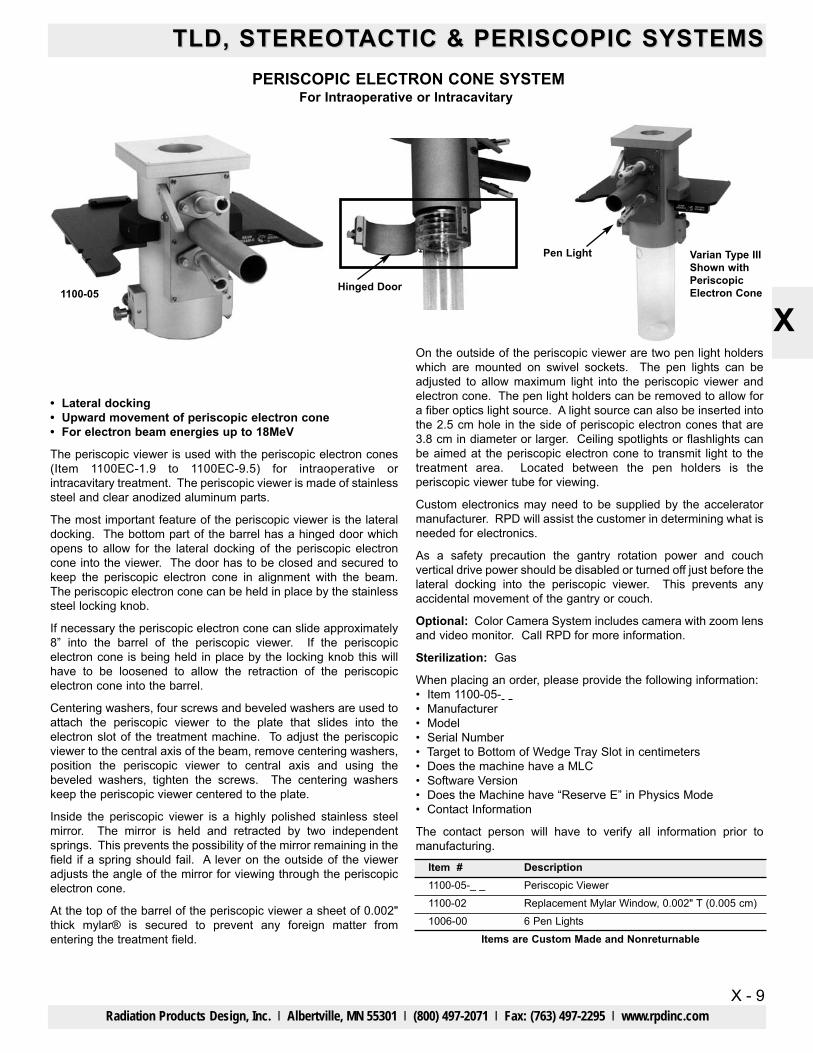
The periscopic viewer is used with the periscopic electron cones(Item 1100EC-1.9 to 1100EC-9.5) for intraoperative orintracavitary treatment. The periscopic viewer is made of stainlesssteel and clear anodized aluminum parts.
The most important feature of the periscopic viewer is the lateraldocking. The bottom part of the barrel has a hinged door whichopens to allow for the lateral docking of the periscopic electroncone into the viewer. The door has to be closed and secured tokeep the periscopic electron cone in alignment with the beam.The periscopic electron cone can be held in place by the stainlesssteel locking knob.
If necessary the periscopic electron cone can slide approximately8” into the barrel of the periscopic viewer. If the periscopicelectron cone is being held in place by the locking knob this willhave to be loosened to allow the retraction of the periscopicelectron cone into the barrel.
Centering washers, four screws and beveled washers are used toattach the periscopic viewer to the plate that slides into theelectron slot of the treatment machine. To adjust the periscopicviewer to the central axis of the beam, remove centering washers,position the periscopic viewer to central axis and using thebeveled washers, tighten the screws. The centering washerskeep the periscopic viewer centered to the plate.
Inside the periscopic viewer is a highly polished stainless steelmirror. The mirror is held and retracted by two independentsprings. This prevents the possibility of the mirror remaining in thefield if a spring should fail. A lever on the outside of the vieweradjusts the angle of the mirror for viewing through the periscopicelectron cone.
At the top of the barrel of the periscopic viewer a sheet of 0.002"thick mylar® is secured to prevent any foreign matter fromentering the treatment field.
On the outside of the periscopic viewer are two pen light holderswhich are mounted on swivel sockets. The pen lights can beadjusted to allow maximum light into the periscopic viewer andelectron cone. The pen light holders can be removed to allow fora fiber optics light source. A light source can also be inserted intothe 2.5 cm hole in the side of periscopic electron cones that are3.8 cm in diameter or larger. Ceiling spotlights or flashlights canbe aimed at the periscopic electron cone to transmit light to thetreatment area. Located between the pen holders is theperiscopic viewer tube for viewing.
Custom electronics may need to be supplied by the acceleratormanufacturer. RPD will assist the customer in determining what isneeded for electronics.
As a safety precaution the gantry rotation power and couchvertical drive power should be disabled or turned off just before thelateral docking into the periscopic viewer. This prevents anyaccidental movement of the gantry or couch.
Optional: Color Camera System includes camera with zoom lensand video monitor. Call RPD for more information.
Sterilization: Gas
When placing an order, please provide the following information:• Item 1100-05-• Manufacturer• Model• Serial Number• Target to Bottom of Wedge Tray Slot in centimeters• Does the machine have a MLC• Software Version• Does the Machine have “Reserve E” in Physics Mode• Contact Information
The contact person will have to verify all information prior tomanufacturing.
Varian Type IIIShown withPeriscopicElectron Cone
Pen Light
Hinged Door1100-05
Item #1100-05-_ _1100-021006-00
DescriptionPeriscopic ViewerReplacement Mylar Window, 0.002" T (0.005 cm)6 Pen Lights
Items are Custom Made and Nonreturnable
TLD, STEREOTTLD, STEREOTACTIC & PERISCOPIC SYSTEMSACTIC & PERISCOPIC SYSTEMS
X - 10
X
Radiation Products Design, Inc. l Albertville, MN 55301 l (800) 497-2071 l Fax: (763) 497-2295 l www.rpdinc.com
SURGICAL DUMMY CONES
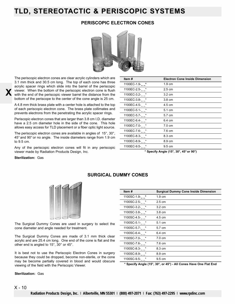
The Surgical Dummy Cones are used in surgery to select thecone diameter and angle needed for treatment.
The Surgical Dummy Cones are made of 3.1 mm thick clearacrylic and are 25.4 cm long. One end of the cone is flat and theother end is angled to 15°, 30° or 45°.
It is best not to use the Periscopic Electron Cones in surgerybecause they could be dropped, become non-sterile, or the conemay be become partially covered in blood and would obscureviewing of the field with the Periscopic Viewer.
Sterilization: Gas
PERISCOPIC ELECTRON CONES
The periscopic electron cones are clear acrylic cylinders which are3.1 mm thick and 30.5 cm long. The top of each cone has threeacrylic spacer rings which slide into the barrel of the periscopicviewer. When the bottom of the periscopic electron cone is flushwith the end of the periscopic viewer barrel the distance from thebottom of the periscope to the center of the cone angle is 25 cm.
A 4.8 mm thick brass plate with a center hole is attached to the topof each periscopic electron cone. The brass plate collimates andprevents electrons from the penetrating the acrylic spacer rings.
Periscopic electron cones that are larger than 3.8 cm I.D. diameterhave a 2.5 cm diameter hole in the side of the cone. This holeallows easy access for TLD placement or a fiber optic light source.
The periscopic electron cones are available in angles of 15°, 30°,45° and 90° or no angle. The inside diameters range from 1.9 cmto 9.5 cm.
Any of the periscopic electron cones will fit in any periscopicviewer made by Radiation Products Design, Inc.
Sterilization: Gas
* Specify Angle (15°, 30°, 45° or 90°)
Item #1100EC-1.9-_ _*1100EC-2.5-_ _*1100EC-3.2-_ _*1100EC-3.8-_ _*1100EC-4.5-_ _*1100EC-5.1-_ _*1100EC-5.7-_ _*1100EC-6.4-_ _*1100EC-7.0-_ _*1100EC-7.6-_ _*1100EC-8.3-_ _*1100EC-8.9-_ _*
Electron Cone Inside Dimension1.9 cm
2.5 cm3.2 cm3.8 cm4.5 cm5.1 cm5.7 cm6.4 cm7.0 cm7.6 cm8.3 cm8.9 cm
1100EC-9.5-_ _* 9.5 cm
* Specify Angle (15°, 30°, or 45°) - All Cones Have One Flat End
Item #1100SC-1.9-_ _*1100SC-2.5-_ _*1100SC-3.2-_ _*1100SC-3.8-_ _*1100SC-4.5-_ _*1100SC-5.1-_ _*1100SC-5.7-_ _*1100SC-6.4-_ _*1100SC-7.0-_ _*1100SC-7.6-_ _*1100SC-8.3-_ _*1100SC-8.9-_ _*
Surgical Dummy Cone Inside Dimension1.9 cm2.5 cm3.2 cm3.8 cm4.5 cm5.1 cm5.7 cm6.4 cm7.0 cm
7.6 cm8.3 cm8.9 cm
1100SC-9.5-_ _* 9.5 cm
TLD, STEREOTTLD, STEREOTACTIC & PERISCOPIC SYSTEMS ACTIC & PERISCOPIC SYSTEMS
X - 11
X
Radiation Products Design, Inc. l Albertville, MN 55301 l (800) 497-2071 l Fax: (763) 497-2295 l www.rpdinc.com
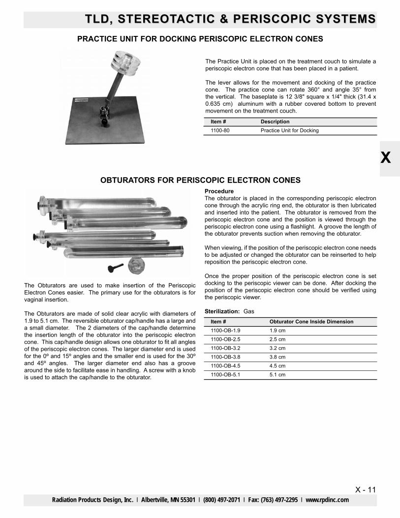
OBTURATORS FOR PERISCOPIC ELECTRON CONES
The Obturators are used to make insertion of the PeriscopicElectron Cones easier. The primary use for the obturators is forvaginal insertion.
The Obturators are made of solid clear acrylic with diameters of1.9 to 5.1 cm. The reversible obturator cap/handle has a large anda small diameter. The 2 diameters of the cap/handle determinethe insertion length of the obturator into the periscopic electroncone. This cap/handle design allows one obturator to fit all anglesof the periscopic electron cones. The larger diameter end is usedfor the 0O and 15O angles and the smaller end is used for the 30O
and 45O angles. The larger diameter end also has a groovearound the side to facilitate ease in handling. A screw with a knobis used to attach the cap/handle to the obturator.
ProcedureThe obturator is placed in the corresponding periscopic electroncone through the acrylic ring end, the obturator is then lubricatedand inserted into the patient. The obturator is removed from theperiscopic electron cone and the position is viewed through theperiscopic electron cone using a flashlight. A groove the length ofthe obturator prevents suction when removing the obturator.
When viewing, if the position of the periscopic electron cone needsto be adjusted or changed the obturator can be reinserted to helpreposition the periscopic electron cone.
Once the proper position of the periscopic electron cone is setdocking to the periscopic viewer can be done. After docking theposition of the periscopic electron cone should be verified usingthe periscopic viewer.
Sterilization: Gas
PRACTICE UNIT FOR DOCKING PERISCOPIC ELECTRON CONES
The Practice Unit is placed on the treatment couch to simulate aperiscopic electron cone that has been placed in a patient.
The lever allows for the movement and docking of the practicecone. The practice cone can rotate 360° and angle 35° fromthe vertical. The baseplate is 12 3/8" square x 1/4" thick (31.4 x0.635 cm) aluminum with a rubber covered bottom to preventmovement on the treatment couch.
Item #1100-80
DescriptionPractice Unit for Docking
Item #1100-OB-1.91100-OB-2.51100-OB-3.21100-OB-3.81100-OB-4.51100-OB-5.1
Obturator Cone Inside Dimension1.9 cm2.5 cm3.2 cm3.8 cm4.5 cm5.1 cm
TLD, STEREOTTLD, STEREOTACTIC & PERISCOPIC SYSTEMSACTIC & PERISCOPIC SYSTEMS
X - 12
X
Radiation Products Design, Inc. l Albertville, MN 55301 l (800) 497-2071 l Fax: (763) 497-2295 l www.rpdinc.com
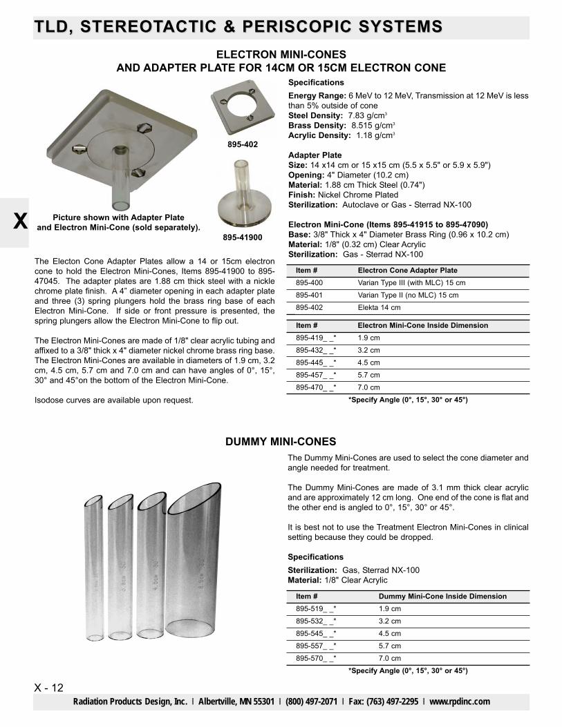
ELECTRON MINI-CONESAND ADAPTER PLATE FOR 14CM OR 15CM ELECTRON CONE
SpecificationsEnergy Range: 6 MeV to 12 MeV, Transmission at 12 MeV is lessthan 5% outside of coneSteel Density: 7.83 g/cm3
Brass Density: 8.515 g/cm3
Acrylic Density: 1.18 g/cm3
Adapter PlateSize: 14 x14 cm or 15 x15 cm (5.5 x 5.5" or 5.9 x 5.9")Opening: 4" Diameter (10.2 cm)Material: 1.88 cm Thick Steel (0.74")Finish: Nickel Chrome PlatedSterilization: Autoclave or Gas - Sterrad NX-100
Electron Mini-Cone (Items 895-41915 to 895-47090)Base: 3/8" Thick x 4" Diameter Brass Ring (0.96 x 10.2 cm) Material: 1/8" (0.32 cm) Clear AcrylicSterilization: Gas - Sterrad NX-100
Picture shown with Adapter Plateand Electron Mini-Cone (sold separately).
DUMMY MINI-CONESThe Dummy Mini-Cones are used to select the cone diameter andangle needed for treatment.
The Dummy Mini-Cones are made of 3.1 mm thick clear acrylicand are approximately 12 cm long. One end of the cone is flat andthe other end is angled to 0°, 15°, 30° or 45°.
It is best not to use the Treatment Electron Mini-Cones in clinicalsetting because they could be dropped.
SpecificationsSterilization: Gas, Sterrad NX-100Material: 1/8" Clear Acrylic
The Electon Cone Adapter Plates allow a 14 or 15cm electroncone to hold the Electron Mini-Cones, Items 895-41900 to 895-47045. The adapter plates are 1.88 cm thick steel with a nicklechrome plate finish. A 4” diameter opening in each adapter plateand three (3) spring plungers hold the brass ring base of eachElectron Mini-Cone. If side or front pressure is presented, thespring plungers allow the Electron Mini-Cone to flip out.
The Electron Mini-Cones are made of 1/8" clear acrylic tubing andaffixed to a 3/8" thick x 4" diameter nickel chrome brass ring base.The Electron Mini-Cones are available in diameters of 1.9 cm, 3.2cm, 4.5 cm, 5.7 cm and 7.0 cm and can have angles of 0°, 15°,30° and 45°on the bottom of the Electron Mini-Cone.
Isodose curves are available upon request.
895-419_ _*895-432_ _*895-445_ _*895-457_ _*
1.9 cm3.2 cm4.5 cm5.7 cm
895-470_ _**Specify Angle (0°, 15°, 30° or 45°)
7.0 cm
Item # Electron Mini-Cone Inside Dimension
895-519_ _*895-532_ _*895-545_ _*895-557_ _*
1.9 cm3.2 cm4.5 cm5.7 cm
895-570_ _**Specify Angle (0°, 15°, 30° or 45°)
7.0 cm
Item # Dummy Mini-Cone Inside Dimension
Item #895-400895-401
Electron Cone Adapter PlateVarian Type III (with MLC) 15 cmVarian Type II (no MLC) 15 cm
895-402 Elekta 14 cm
895-402
895-41900