tm 11-6140-224-13&p direct support maintenance …
TRANSCRIPT

TM 11-6140-224-13&P
TECHNICAL MANUAL
OPERATOR’S, ORGANIZATIONAL AND
DIRECT SUPPORT MAINTENANCE
INCLUDING REPAIR PARTS AND
SPECIAL TOOLS LISTBATTERY, STORAGE
BB-542/U (NSN 6140-01-089-7636)
(NICKEL-CADMIUM SEALED)
HEADQUARTERS, DEPARTMENT OF THE ARMY5 MARCH 1985
TM 11-6140-224-13&P
TECHNICAL MANUAL
OPERATOR’S, ORGANIZATIONAL AND
DIRECT SUPPORT MAINTENANCE
INCLUDING REPAIR PARTS AND
SPECIAL TOOLS LISTBATTERY, STORAGE
BB-542 / U (NSN 6140-01-089-7636)
(NICKEL-CADMIUM SEALED)
HEADQUARTERS, DEPARTMENT OF THE ARMY5 MARCH 1985
TM 11-6140-224-13&P
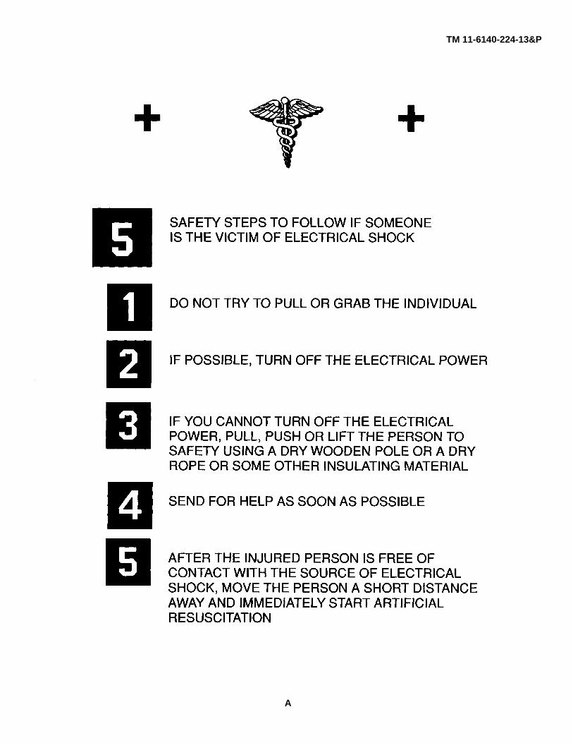
A
TM 11-6140-224-13&P
WARNINGS
l Sealed Nickel-Cadmium (NICAD) batteries contain potassium hydroxide(KOH), which is a caustic agent. Serious and deep burns of body tissuewill result if the electrolyte comes in contact with the eyes or any part ofthe body.
l If batteries show signs of leaking use rubber gloves, rubber apron andprotective goggles. Follow FIRST AID instructions if you believe anycaustic has gotten on you.
FIRST AID INSTRUCTIONS
1. In the event of contact with the eyes, immediately flush eyes with water and continue to flush for 15 minutes.
l The first few seconds after contact are critical and immediate flushing ofthe eyes may prevent damage. An eyewash fountain is preferred,however, an eyewash hose or any other source of clean water should beused in an emergency.
2. For other parts of the body, begin flushing the area with large quantities of clean water immediately.
3. After flushing, seek medical attention without delay. Inform medical personnel that you have been contaminatedwith potassium hydroxide.
4. The precautionary warnings on the product label should be consulted for full first-aid information. Provide the labelinformation to the attending physician.
5. Neutralizers and solvents (alcohol, etc.) should not be used by the first aider. The spread of skin absorbingcorrosive poison, like phenol, can result in death. (Don’t depend upon spilled chemicals to evaporate from your clothes.Exposure of skin can kill you.)
FIRE FIGHTING SAFETY PRACTICE
"In the event of fire use a C02 fire extinguisher."
B
TM 11-6140-224-13&P
Technical Manual HEADQUARTERSNo. 11-6140-224-13&P DEPARTMENT OF THE ARMY
Washington, DC, 5 March 1985
OPERATOR’S ORGANIZATIONAL ANDDIRECT SUPPORT MAINTENANCE MANUAL
INCLUDING REPAIR PARTS AND SPECIAL TOOLS LISTBATTERY, STORAGE
BB-542/U (NSN 6140-01-089-7636)(NICKEL-CADMIUM SEALED)
REPORTING ERRORS AND RECOMMENDING IMPROVEMENTS
You can help improve this manual. If you find any mistakes or if you know of a way toimprove the procedures, please let us know. Mail your letter, DA Form 2028(Recommended Changes to Publications and Blank Forms), or DA Form 2028-2located in back of this manual direct to: Commander, US Army Communications-Electronics Command and Fort Monmouth, ATTN: AMSEL-ME-MP, Fort Monmouth,New Jersey 07703-5007. In either case, a reply will be furnished direct to you.
TABLE OF CONTENTS
Paragraph PageCHAPTER 1. INTRODUCTION
Scope ..................................................................................................1-1 1-1Consolidated Index of Army Publications and
Blank Forms ..............................................................................................1-2 1-1Maintenance Forms, Records, and Reports ....................................................1-3 1-1Reporting Equipment Improvement
Recommendations (EIR) ...........................................................................1-4 1-1Administrative Storage.....................................................................................1-5 1-1Destruction of Army Electronics Materiel .........................................................1-6 1-1
CHAPTER 2. SPECIFIC DATA FOR BB-542/U BATTERYTabulated Data for BB-542/U...........................................................................2-1 2-1Characteristics with Outstation Equipment ......................................................2-2 2-1Description of BB-542/U .................................................................................2-3 2-2
CHAPTER 3. INSTALLATIONUnpacking ..................................................................................................3-1 3-1Checking Unpacked Equipment ......................................................................3-2 3-1Battery Service Record ....................................................................................3-3 3-1Installation of Battery, Storage BB-542/U ........................................................3-4 3-1Emergency Procedures ...................................................................................3-5 3-1Functioning of BB-542/U..................................................................................3-6 3-2
i

TM 11-6140-224-13&P
TABLE OF CONTENTS - Continued
Paragraph PageCHAPTER 4. ORGANIZATIONAL MAINTENANCE
Scope of Organizational Preventive Maintenance...........................................4-1 4-1Preventive Maintenance...................................................................................4-2 4-1Organizational Preventive Maintenance Checks and
Services ..................................................................................................4-3 4-1Operator Daily Preventive Maintenance Checks and
Services Chart (at Equipment Site) .............................................................4-4 4-1Organizational Weekly Preventive Maintenance
Checks and Services Chart for Battery BB-542/U .......................................4-5 4-1Organizational Monthly Preventive Maintenance
Checks and Services Chart ..........................................................................4-6 4-2Visual Inspection..............................................................................................4-7 4-2Organizational Testing .....................................................................................4-8 4-2Electrical Leakage Test....................................................................................4-9 4-2Battery Voltage Test.........................................................................................4-10 4-3Charging Procedures .......................................................................................4-11 4-3Discharge ..................................................................................................4-12 4-5Storage ..................................................................................................4-13 4-5Cleaning Storage Battery.................................................................................4-14 4-5Organizational Repair of Battery, Storage BB-542/U.......................................4-15 4-5Organizational Troubleshooting Chart .............................................................4-16 4-5
CHAPTER 5. DIRECT SUPPORT MAINTENANCEGeneral Instructions.........................................................................................5-1 5-1Test Equipment, Tools, and Materials .............................................................5-2 5-1Constant Current Charging Procedure ...........................................................5-3 5-1Direct Support Troubleshooting Chart ............................................................5-4 5-1Capacity Discharge Test .................................................................................5-5 5-1Administrative Storage of Nickel-Cadmium
Batteries ..................................................................................................5-6 5-2Disposition of NICAD Batteries .......................................................................5-7 5-2
APPENDIX A. REFERENCES ................................................................................................ A-1
APPENDIX B. MAINTENANCE ALLOCATIONSection I. Introduction .................................................................................................. B-1
II. Maintenance Allocation Chart .......................................................................... B-3III. Tool and Test Equipment Requirements ........................................................ B-4IV. Remarks .................................................................................................. B-5
APPENDIX C. ORGANIZATIONAL AND DIRECT SUPPORTMAINTENANCE REPAIR PARTS AND SPECIALTOOLS LIST
Section I. Introduction .................................................................................................. C-1II. Repair Parts List .............................................................................................. C-1
Group 00 Battery, Storage BB-542/U .............................................................................. C-1-1III. Special Tools List (Not applicable)IV. National Stock Number and Part Number Index.............................................. C-I-1
ii

TM 11-6140-224-13&P
LIST OF ILLUSTRATIONS
Number Title Page
1-1 Battery, Storage BB-542/U (Nickel-Cadmium Sealed)............................................................... 1-22-1 Battery, Storage BB-542/U......................................................................................................... 2-32-2 BB-542/U Schematic Diagram ................................................................................................... 2-43-1 Battery, Storage BB-542/U, Packaging Diagram ....................................................................... 3-24-1 Jumper Plug Fabrication ............................................................................................................ 4-44-2 BB-542/U Low Temperature Charging....................................................................................... 4-65-1 Pressure Switch Turning ............................................................................................................ 5-5
LIST OF TABLES
Number Page
4-1 Recommended Charge Conditions with Power Supply for OptimumPerformance .................................................................................................................... 4-3
4-2 Organizational Troubleshooting Chart........................................................................................ 4-75-1 Direct Support Troubleshooting Chart........................................................................................ 5-3
iii/(iv blank)

TM 11-6140-224-13&PCHAPTER 1
INTRODUCTION
1-1. ScopeThis manual covers the specific data, maintenance and repair instructions, installation, operation and testing of Battery,Storage BB-542/U (Nickel-Cadmium Sealed) (see fig. 1-1). It is a sealed, fast charge storage battery which provides a 24volt, direct current (dc) power source. The BB-542/U is used to supply operating power for various electronic equipmentsby itself or in conjunction with the G-76/G hand-cranked generator.
1-2. Consolidated Index of Army Publications and Blank FormsRefer to the latest issue of DA PAM 310-1 to determine whether there are new editions, changes, or additional publicationspertaining to the equipment.
1-3. Maintenance Forms, Records, and Reportsa. Reports of Maintenance and Unsatisfactory Equipment. Department of the Army forms and procedures used forequipment maintenance will be those prescribed by DA PAM 738-750, as contained in Maintenance Management Update.b. Report of Packaging and Handling Deficiencies. Fill out and forward SF 364 (Report of Discrepancy (ROD)) asprescribed in AR 735-11-2/DLAR 4140.55/NAVMATINST 4355.73A/AFR400-54/MCO4430.3F.c. Discrepancy in Shipment Report (DISREP) (SF 361). Fill out and forward Discrepancy in Shipment Report(DISREP) (SF 361) as prescribed in AR 55-38/NAVSUPINST 4610.33C’AFR 75-18/MCO P4610.19D/ DLAR4500.15
1-4. Reporting Equipment Improvement Recommendations (EIR)If your BB-542/U needs improvement, let us know. Send us an EIR. You, the user, are the only one who can tell us whatyou don’t like about your equipment. Let us know why you don’t like the design. Put it on an SF 368 (Quality DeficiencyReport). Mail it to Commander, US Army Communications-Electronics Command and Fort Monmouth, ATTN: AMSEL-ME-MP, Fort Monmouth, NJ 07703-5007. We’ll send you a reply.
1-5. Administrative StorageAdministrative Storage of equipment issued to and used by Army activities will have preventive maintenance performed inaccordance with the PMCS charts before storing. When removing the equipment from administrative storage, the PMCSshould be performed to assure operational readiness. Disassembly and repacking of equipment for shipment or limitedstorage are covered in paragraph 5-6.
1-6. Destruction of Army Electronics MaterielDestruction of Army electronics materiel to prevent enemy use shall be in accordance with TM 750-244-2.
1-1

TM 11-6140-224-13&P
Figure 1-1. Battery, Storage BB-542/U (Nickel-Cadmium Sealed).
1-2

TM 11-6140-224-13&PCHAPTER 2
SPECIFIC DATA FOR BB-542/U BATTERY
2-1. Tabulated Data for BB-5421U
Type ........................................................................................................Nickel-Cadmium (sealed)Number of cells ...........................................................................................20Electrolyte....................................................................................................Potassium hydroxide (KOH)Operating Range:
Temperature................................................................................... -25°F (-32°C) to 125°F (520C)Atmospheric Pressure ....................................................................Sea level to 100,000 feet
Storage:Duration (maximum).......................................................................Unlimited, regardless of state of chargeTemperature................................................................................... -80°F (-62.20C) to 125°F (520C)Atmospheric Pressure ...................................................................Sea level to 100,000 feet
Electrical Data:Rated 1-hour discharge capacity at temperature of:
Approximately 75°F(23.90C)..................................................2.0 ampere-hours at 24 voltsApproximately OF(-17.8°C)....................................................1.2 ampere-hours at 24 voltsApproximately-25°F (32°C) ....................................................0.5 ampere-hours at 24 volts
Current at Temperature:Approximately 75°F (23.90C) ........................................................10 amperes for 8 minutes at 23 volts 400
milliamperes for 5 hours at 24 voltsApproximately 25°F(32°C) 2.0 amperes for 15 minutes above 20 volts,
400 milliamperes for 3.3 hours at 24 voltsVoltage:
Open circuit ....................................................................................Approximately 26 volts (fully charged with a24-hour rest period)
Minimum life cycle (charge and discharge) .................................................500 cyclesWeight ........................................................................................................7 pounds maximumSize ........................................................................................................2.56 inches high, 12.2 inches long, and 4.0 in-
ches wide
2-2. Characteristics with Outstation EquipmentThe service time obtainable (before recharge) from the BB-542/U is a function of the specific radio equipment. Typicalcapabilities at 700F are given below:
USE MODE TYPICAL SERVICE TIMESEQUIPMENT
Intermittent-Receive 40 min/day AN/PRC-70 AN/PSC-1(SAT) AN/PSC-1(LOS)and Transmit 1 min/week 10 daysor Transmit 2 min/day 5 days 5 days 7 days
Continuous 1/9 Transmit/Receive 2-1/4 hr 2-3/4 hr 4-3/4 hrContinuous Receive 8 hours 7 hours 7 hoursContinuous Transmit 15 minutes 20 minutes 66 minutes
2-1

TM 11-6140-224-13&P
2.3. Description of BB-5421UThe BB-5421U is a rechargeable 24-volt, 2 ampere hour, sealed nickel-cadmium battery containing 20 cells, charge controland internal heating elements (fig. 2-1) with a capability of being charged in approximately 20 to 60 minutes under alltemperature conditions. The BB-5421U is designed to mate directly with the AN/PRC-70 radio by mounting under the radio.A connector (MS3112E:14-5S) is provided on the side of the battery for cable connection with a G-76/G handcrankedgenerator or other power sources, so that the battery car be recharged and/or a AN/PRC-70 radio directly powered. TheBB-542/U contains controls designed to prevent overcharge, overdischarge, or rapid charging at extreme low temperatureconditions internal to the battery. Figure 2-2 is a schematic detailing the various control elements.a. Cell Construction. Each of the 20 cells consists of a sealed cylindrical can containing the battery plates. The cellsare nonspillable and can operate in any position. Two of the 20 cells are equipped with pressure switches for chargetermination.b. Electrolyte. The electrolyte which is a solution of potassium hydroxide (KOH) is completely contained within thecells and requires no additions or changes throughout the life of the batteryc. Battery Box. The battery box provides a waterproof container for the cells, when used with the transmit cover ormounted under the using radios. Two latches are provided for mounting to the catches on the radio. A manual vent reliefvalve is located in the end of the battery box to release any vacuum induced by air transport.d. Heater. A thermostatically controlled heating element of 10 ohm resistance, which provides 130 watts of heat at a36 volt input, is located in two parts, one under and one on top of the battery cells. Heat transfer paste is employed torapidly transfer heat to the cells.e. Control Circuits. Overcharge is prevented by stopping the charge when either one of two pressure switch equippedcells measures an over-pressure condition, which signals the start of overcharge. Overdischarge is prevented byterminating discharge when the battery voltage falls to approximately 20 volts. In order to accomplish this function withoutexcessive drain currents, the discharge cutoff uses a magnetic latch relay and a microampere sensing circuit which doesnot drain the battery on standby. A fuse is provided in the event of short circuiting to protect the control elements. Lowtemperature protection is provided by a thermostatically controlled charge limiter and a heater circuit which warms thebattery prior to the start of rapid charge.
2-2

TM 11-6140-224-13&P
Figure 2-1. Battery, Storage BB-542/U.
2-3

TM 11-6140-224-13&P
Figure 2-2. Battery, Storage BB-542/U Schematic Diagram.
2-4
TM 11-6140-224-13&PCHAPTER 3
INSTALLATION
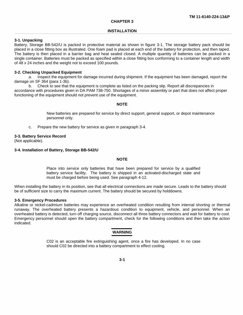
3-1. UnpackingBattery, Storage BB-542/U is packed in protective material as shown in figure 3-1. The storage battery pack should beplaced in a close fitting box as illustrated. One foam pad is placed at each end of the battery for protection, and then taped.The battery is then placed in a barrier bag and heat sealed closed. A multiple quantity of batteries can be packed in asingle container. Batteries must be packed as specified within a close fitting box conforming to a container length and widthof 48 x 24 inches and the weight not to exceed 100 pounds.
3-2. Checking Unpacked Equipmenta. Inspect the equipment for damage incurred during shipment. If the equipment has been damaged, report the
damage on SF 364 (para 1-3b).b. Check to see that the equipment is complete as listed on the packing slip. Report all discrepancies in
accordance with procedures given in DA PAM 738-750. Shortages of a minor assembly or part that does not affect properfunctioning of the equipment should not prevent use of the equipment.
NOTE
New batteries are prepared for service by direct support, general support, or depot maintenance personnel only.
c. Prepare the new battery for service as given in paragraph 3-4.
3-3. Battery Service Record(Not applicable).
3-4. Installation of Battery, Storage BB-542/U
NOTE
Place into service only batteries that have been prepared for service by a qualifiedbattery service facility. The battery is shipped in an activated-discharged state andmust be charged before being used. See paragraph 4-12.
When installing the battery in its position, see that all electrical connections are made secure. Leads to the battery shouldbe of sufficient size to carry the maximum current. The battery should be secured by holddowns.
3-5. Emergency ProceduresAlkaline or nickel-cadmium batteries may experience an overheated condition resulting from internal shorting or thermalrunaway. The overheated battery presents a hazardous condition to equipment, vehicle, and personnel. When anoverheated battery is detected, turn off charging source, disconnect all three battery connectors and wait for battery to cool.Emergency personnel should open the battery compartment, check for the following conditions and then take the actionindicated.
WARNING
C02 is an acceptable fire extinguishing agent, once a fire has developed. In no caseshould C02 be directed into a battery compartment to effect cooling.
3-1
TM 11-6140-224-13&P
Figure 3-1. Battery, Storage BB-542/U, Packaging Diagram.
3-2

TM 11-6140-224-13&P
a. If no flame is present allow battery to cool and ventilate battery box. If necessary a water spray may be used tocool the battery box.b. If flame is present, use a C02 fire extinguisher.
3-6. Functioning of the BB-5421UThe application of electrical energy to the storage battery (charging) causes the storage of a corresponding amount ofchemical energy within its plates; the storage of chemical energy is accomplished through changes in the composition ofthe plate materials. When an electrical load is connected to the storage battery (discharging), the stored chemical energy isconverted into a flow of electrical current through the load. In a sealed nickel-cadmium storage battery the specific gravityof the electrolyte cannot be measured to give an indication of the state of charge.a. Charging. When the charging current (electrical energy) is applied to the storage battery, the cadmium-oxidematerial of the negative plates gradually becomes metallic cadmium. The nickel oxide material of the positive plates isbrought to a higher state of oxidation. These changes (in both sets of plates) continue as long as the charging current isapplied. Toward the end of this process, the cell generates gas because of the evolution of oxygen at the positive plates. Atlow rates of overcharge, i.e., 200mA, all the oxygen generated at the positive reacts with the negative electrode to maintainthe composition of the components of the cell unchanged. The steady state pressure reached within the cells is very low.At higher rates of overcharge, i.e., 3A, enough pressure can be rapidly generated to cause cell venting if the charge is notstopped soon enough after overcharge and oxygen generation begins. In the BB-542/U the amount of overcharge iscontrolled by measuring the pressure in 2 of the cells of the battery and automatically terminating the charge once apressure of approximately 10 psig is reached in one of the two control cells. When the battery stands, its internal pressuredrops so that the pressure switches will cycle the charging current off and on If the battery is not removed from thecharging source.b. Discharging. When a load is connected to the storage battery, a reverse chemical action is immediately initiated.The positive plates gradually return to a state of lower oxidation, and the negative plates change from metallic cadmium tocadmium oxide. During this process, the amount of chemical energy that is converted to current flow is determinedprincipally by the resistance of the load. In order to prevent reversal of any cells during deep discharge, the BB-542/U isequipped with an internal discharge cutoff which will automatically disconnect the battery from the load when the batteryvoltage falls to 20 volts. The battery will remain disconnected until a charging source of 28 volts, or higher, is connected tothe battery.
3-3/(3-4 blank)

TM 11-6140-224-13&PCHAPTER 4
ORGANIZATIONAL MAINTENANCE
4-1. Scope of Organizational Preventive MaintenanceThe preventive maintenance duties assigned to the operator and organizational repair technician for the BB-542/U arelisted below, together with a reference to the paragraph covering the specific preventive maintenance functions. Refer tothe MAC Section III, Appendix B, for a list of tools and test equipment required for organizational maintenance.
a. Visual Inspection - paragraph 4-7b. Electrical Leakage Test - paragraph 4-9c. Battery Voltage Test - paragraph 4-10d. Battery Charging - paragraph 4-11e. Cleaning - paragraph 4-14
4.2. Preventive MaintenancePreventive maintenance is the systematic care, servicing, and checking of nickel-cadmium batteries to prevent occurrenceof trouble, reduce downtime, and ensure that the equipment is serviceable.
a. Systematic Care. Procedures given in paragraphs 4-4 through 4-15 cover routine systematic care andcleaning essential to the proper upkeep of the battery.
b. Preventive Maintenance Checks and Services. The preventive maintenance checks and services charts (para4-4, 4-5 and 4-6) outline checks and services to be performed at specific intervals. These checks and services are tomaintain the BB-542/U in a combat-serviceable condition.
4-3. Organizational Preventive Maintenance Checks and ServicesOrganizational preventive maintenance checks and services of the BB-542/U are required weekly and monthly.
a. Paragraph 4-5 specifies checks and services that must be accomplished weekly.b. Paragraph 4-6 specifies checks and services that must be accomplished monthly.
4-4. Operator Daily Preventive Maintenance Checks and Services Chart (At Equipment Site)
Sequence Item to beNo. Inspected Procedure Reference
1 Overall Battery Clean top of cover.
2 Overall Battery During operation be alert Nonefor any abnormal con-dition.
4-5. Organizational Weekly Preventive Maintenance Checks and Services Chart for Battery BB-542/U
Sequence Item to beNo. Inspected Procedure Reference
1 Battery BB-542/U Inspect battery. Paragraph 4-7
2 Battery BB-542/U Check battery voltage. Paragraph 4-10
3 Battery BB-542/U Charge battery. Paragraph 4-11
4-1

TM 11-6140-224-13&P
4-6. Organizational Monthly Preventive Maintenance Checks and Services Chart
Sequence Item to beNo. Inspected Procedure Reference
1 Overall Battery Inspect battery. Paragraph 4-7
2 Overall Battery Clean battery. Paragraph 4-14
3 Overall Battery Charge battery. Paragraph 4-11
4 Overall Battery Check leakage current Paragraph 4-9of each battery.
4-7. Visual InspectionMany causes of battery failure may be detected by visual inspection. Because the battery cannot be disassembled by anorganizational repair technician, visual inspection is limited to observing the assembled battery. Only the fuse and dust capcan be replaced, obvious corrosion or contamination cleaned and loose nuts tightened at organization maintenance; for allother damages refer to higher category of maintenance. Release the snap fasteners and remove the battery cover. Checkthe storage battery for damage as indicated in (a) through (e) below:
a. Battery box or cover scratched or dented.b. Connectors bent or broken.c. Connector cover missing or bent.d. Loose or missing control module holddown nuts.e. Blown or missing fuse.
4-8. Organizational TestingTesting will supplement the visual inspection in determining the cause of troubles which may occur in the storage battery.The tests given in paragraphs 4-9 and 4-10 may indicate an inoperative control module, defective cells, open wiring, orelectrical leakage between the cells and the battery box.
4-9. Electrical Leakage TestPrior to performing this check of the battery, all electrical cables should be disconnected from the unit under test. Theelectrical leakage test will indicate conditions that may cause the storage battery to discharge faster than normal or todischarge when not in use.
a. Use Multimeter, or equivalent, set to indicate on the 50 volt scale at 1,000 ohms per volt.b. Connect positive lead of multimeter to positive (+) terminal of battery connector.c. Connect negative lead to bare metal or unpainted area of case or connector shells.d. If the TS-352B/U indicates less than 1 volt, set it to indicate on the 10 volt scale at 1,000 ohms per volt. The
voltage indicated must be less than 1 volt.
NOTE
If the voltage is greater than 1 volt, leakage is present. The battery should be turned over to support maintenance.
e. Connect negative lead of multimeter to negative (-) terminal of battery.f. Connect positive lead of multimeter to unpainted area of battery case such as the latches or screws on the
connector.g. Indications should be the same as those obtained in d above. If both indications are below 1 volt return battery to
normal service.
4-2

TM 11-6140-224-13&P
4-10. Battery Voltage TestCheck the voltage of the BB-542,/U with the TS-352B/U or equivalent as follows:
a. Read between Pin 1 (minus) and Pin 5 (plus) on the top of 6 pin connector.b. If recently charged, voltage should be approximately 26 volts or higher.c. If zero voltage is read, apply 30 volt charging source (para 4-11) to battery for 1 minute. Listen for relay"click" when voltage is first applied.d. Zero voltage after a 30 volt charging source is applied may indicate a defective control module.
NOTE
Low voltage (25 volts or less) may indicate defective cells, pressure switch con-trols, or thermal switch. However it may also be due to normal discharge of thebattery.
4-11. Charging ProceduresThe battery may be charged from any controlled power supply having an available voltage between 30 and 36 volts, and acurrent capability between 200 mA and 6 amperes. However, best results will be obtained by using modified constantpotential charger with the current limited to 2 to 3 amperes, and the voltage set at 31.1 volt. At 2 amperes, 1-1/4 hours arerequired for a full charge. At 3 amperes, only 45 to 60 minutes are needed. Charging should be carried out at a batterytemperature of 50-90"F (10-32°C). Charging at 32 to 125°F (0-520C) is permitted, but will result in a slight reduction incapacity. Below 30"F, rapid charging will be inhibited by the internal thermal controls and will not take place unless power isalso provided to the heater circuit. Recommended charging conditions for optimum performance are given in Table 4-1.
Table 4-1. Recommended Charge Conditions with Power Supply for Optimum Performance
BatteryTemperature Current Voltage Time
90-125"F 3A 30-32V 1 hour
50-90"F 2A 30-32V 1-1/4 hours
30-50"F 1A 30-32V 2-1/2 hours
Under 30°F ∗ 4A ∗ 30-32V 1-1/2 hours
∗ Power required for internal heater
a. Charging from a Power Supply at Low Temperatures. Set power supply to specific current and voltage limits.Connect power supply to BB-542/U through top 6 pin connector using cable ES-D-212028 to any power supply with bananatype outputs. Turn on power supply. Connect jumper plug fabricated as shown in figure 4-1 to 5 pin MS3112E-14-5Sconnector on side of battery. This will energize heater circuit.
CAUTION
Jumper plug must be removed except when power is being provided from power supply or battery will be discharged.
NOTE
Insulate battery from external environment to the greatest extent possible Wrap in towel, sleeping bag, etc.
4-3

TM 11-6140-224-13&P
Figure 4-1. Jumper Plug Fabrication
b. Charging with G-76/G Handcranked Generator.(1) Temperature above 50°F. Connect cable from G-76/G to MS3112E-14-55 connector on side of battery. Crank
generator at a speed sufficient to cause 2 ampere indicator light on generator to turn on. Continue cranking at 2 ampererate until load suddenly lowers due to opening of pressure switch within the battery. The 3A light on generator will beextinguished and will not turn on, no matter how fast the generator is cranked. Battery is now fully charged.
(2) Temperature between 30° and 500F. Connect cable from G-76/G to MS3112E-14-55 connector on side ofbattery. Crank generator at a speed sufficient to cause 2 ampere indicator light on a generator to turn on. Continuecranking until G-76/G light goes out and stays out irrespective of charging speed. This will indicate that the battery is fullycharged. At temperatures between 300 and 500F, the load on the generator may not change significantly when thepressure switch opens because the heater circuit will start drawing power after the battery is fully charged. The G-76/Gdoes not provide any indication of the current in the heater circuit. The battery may also be charged intermittently as above.
(3) Temperatures below 30°F. At temperatures much below 300F intermittent charging is not recommendedbecause a significant amount of cranking energy will be required to bring the battery to 30°F before high rate charging willstart. The suggested procedures for minimum cranking time and effort is as follows:
(a) Start with a battery that is almost completely discharged.(b) Keep battery in heated area if possible.(c) Wrap battery with insulating material such as blanket, sleeping bag, coat, etc. to prevent heat loss.(d) Crank at highest sustained rcte possible, use a 2 person cranking to minimize exposure time and resulting
heat loss.For each 10°F the battery is below 30°F, 2 minutes of heating at 130 watts, or 3 minutes at 3 ampere (90 watts),
will be required before high rate charging will start. Thus, with the battery at -200F, approximately 10-15 minutes of heatingwill be required to bring it to 30°F where high rate charging can begin. When high rate charging starts, the current will beautomatically switched by G-76/G generator from the heater to the battery. At this time the 2 ampere light will go on if thegenerator is being cranked at a fast enough rate. If the external temperature is low, the heater will switch on for 2 to 3minute periods every 5 to 10 minutes during the charge, extinguishing the 2 ampere light on the generator while stillmaintaining a load on the generator. Total charge time at a 90 watt power input level will vary from about 45 minutes at200F to 65 minutes at -25°F. Figure 4-2 is a typical curve showing the on-off heating characteristics at a fixed crankingspeed.
4-4

TM 11-6140-224-13&P
20°F to 65 minutes at -250F. Figure 4-2 is a typical curve showing the on-off heating characteristics at a fixed crankingspeed.
After the battery has been completely charged the heater load will still be maintained on the G-76/G generator untilthe battery temperature reaches approximately 500F. It is therefore difficult to determine when cranking can be stopped;however, if cranking has continued continuously at 2 amperes or above for the times given previously and the 2 amperelight cannot be lit after 3 minutes of additional cranking, then the battery is fully charged.
4-12. DischargeThe battery is designed to be discharged at currents up to 10 amperes Currents in excess of 15 arnperes or temporaryshorting of output loads will cause the battery fuse to blow. The battery is equipped with an automatic discharge cutoffwhich will stop the discharge of the battery when its voltage falls to 20 volts. The battery cannot be discharged again andwill read 0 volts at the output terminals unless it is exposed to an input voltage greater than 28 volts, which will reset thelatch relay contacts. The battery is capable of 500 or more charge-discharge cycles however. operating, at temperaturesabove 120°F tends to degrade performance. Reduced performance is obtained at temperatures of -25°F to -40°Fparticularly for low currents associate,? with the radio receive loads.
4-13. StorageThe battery is capable of extended storage (up to 5 years) if temperature excursions above 120°F are limited. Chargeretention in storage is dependent on temperature. Capacity loss will average approximately 4% per day at 120°F, 1% perday at 70°F, and 0.3% per day at 30°F.
4-14. Cleaning Storage BatteryNormal cleaning of nickel-cadmium battery involves removing the battery box cover. Clean battery by removing dirt andcorrosion from connectors and other visible hardware. Do not use solvents for cleaning the storage battery.
4-15. Organizational Repair of Battery, Storage BB-542/URepair of the storage battery at the organizational maintenance category consists of replacing fuses and dust caps,cleaning obvious corrosion and dirt, and tightening loose screws.
WARNING
The storage battery is charged and will cause bodily injury and equipmentdamage if the cells or internal connections are short-circuited, or if the fuse isbypassed and the external connectors are short-circuited.
a. Removal and Replacement of Dust Cap.(1) Remove the screw that holds the dust cap keeper chain to the battery.(2) Place new dust cap in position on connector.(3) Secure the dust cap by inserting the screw and tightening it to the battery.
b. Removal and Replacement of Fuse.(1) Disconnect all external loads.(2) Remove defective fuse from fuseholder.(3) Examine fuseholder contacts for dirt or corrosion.(4) Remove spare fuse from holder.(5) Place spare fuse in fuseholder.
c. Tightening Screws and Nuts. The only screws and nuts that should be tightened by the operatorare those holding the MS3112E-14-55S connector and the four screws holding the control module to the battery.
4-16. Organizational Troubleshooting ChartThe organizational troubleshooting chart, Table 4-2, will aid in isolating troubles that occur in the BB-542/U.
4-5

TM 11-6140-224-13&P
Figure 4.2. BB-542/U Low Temperature Charging.
4-6
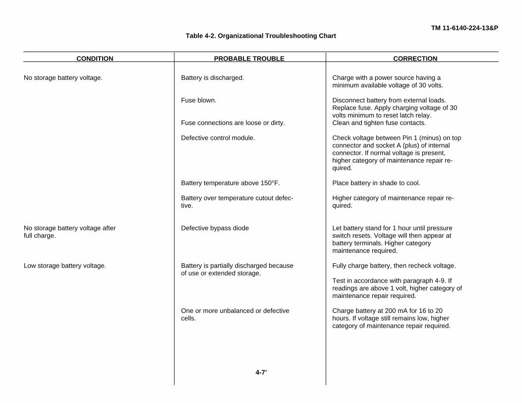
TM 11-6140-224-13&PTable 4-2. Organizational Troubleshooting Chart
CONDITION PROBABLE TROUBLE CORRECTION
No storage battery voltage. Battery is discharged. Charge with a power source having aminimum available voltage of 30 volts.
Fuse blown. Disconnect battery from external loads.Replace fuse. Apply charging voltage of 30volts minimum to reset latch relay.
Fuse connections are loose or dirty. Clean and tighten fuse contacts.
Defective control module. Check voltage between Pin 1 (minus) on topconnector and socket A (plus) of internalconnector. If normal voltage is present,higher category of maintenance repair re-quired.
Battery temperature above 150°F. Place battery in shade to cool.
Battery over temperature cutout defec- Higher category of maintenance repair re-tive. quired.
No storage battery voltage after Defective bypass diode Let battery stand for 1 hour until pressurefull charge. switch resets. Voltage will then appear at
battery terminals. Higher categorymaintenance required.
Low storage battery voltage. Battery is partially discharged because Fully charge battery, then recheck voltage.of use or extended storage.
Test in accordance with paragraph 4-9. Ifreadings are above 1 volt, higher category ofmaintenance repair required.
One or more unbalanced or defective Charge battery at 200 mA for 16 to 20cells. hours. If voltage still remains low, higher
category of maintenance repair required.
4-7’
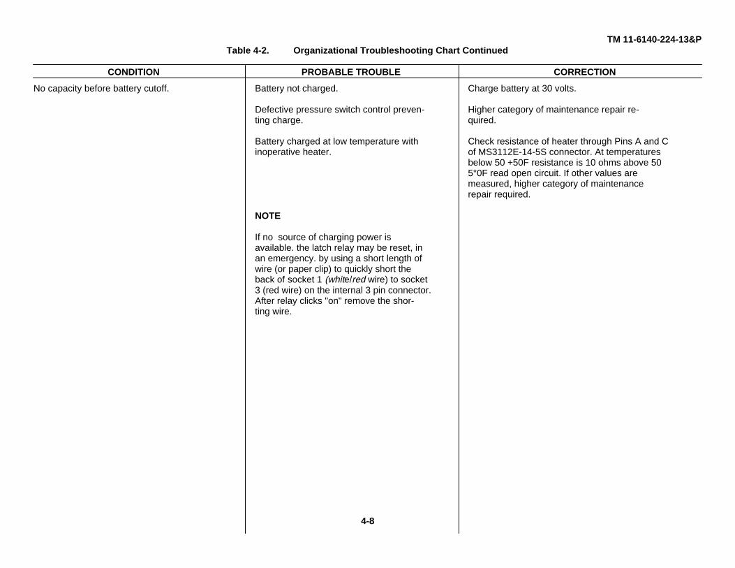
TM 11-6140-224-13&PTable 4-2. Organizational Troubleshooting Chart Continued
CONDITION PROBABLE TROUBLE CORRECTION
No capacity before battery cutoff. Battery not charged. Charge battery at 30 volts.
Defective pressure switch control preven- Higher category of maintenance repair re-ting charge. quired.
Battery charged at low temperature with Check resistance of heater through Pins A and Cinoperative heater. of MS3112E-14-5S connector. At temperatures
below 50 +50F resistance is 10 ohms above 505°0F read open circuit. If other values aremeasured, higher category of maintenancerepair required.
NOTE
If no source of charging power isavailable. the latch relay may be reset, inan emergency. by using a short length ofwire (or paper clip) to quickly short theback of socket 1 (white/red wire) to socket3 (red wire) on the internal 3 pin connector.After relay clicks "on" remove the shor-ting wire.
4-8

TM 11-6140-224-13&P
CHAPTER 5
DIRECT SUPPORT MAINTENANCE
5-1. General InstructionsThe direct support maintenance procedures given in paragraphs 5-3, 5-4 and 5-5 supplement the procedures describedfor the organizational maintenance repairman. Tools, materials, and test equipment required for maintenance are listed inparagraph 5-2 and Appendix B, Section III. Direct support, general support, and depot maintenance for the storage batteryconsists of the following:
a. Constant Current Charging Procedure - paragraph 5-3b. Direct Support Troubleshooting Chart - paragraph 5-4c. Capacity Discharge Test - paragraph 5-5
5-2. Test Equipment, Tools, and Materialsa. Power Supply, PP-6148/Ub. Cable Assembly ES-D-212025, orc. Cable Assembly ES-D 212028d. Multimeter TS-352BfU, or equivalente. Resistor 20 ohms, 50 wattf. Resistor, Variable, 0-7.5 ohms, 1,000 watt (NSN 5905-00-195-4496)
5-3. Constant Current Charging Procedurea. Place the storage battery on a clean dry surface as close as possible to the PP-6148/U, or equivalent power
supply.b. Release the two snap fasteners and remove the cover from the battery case.c. Turn on power and adjust the PP-6148/U to the current and voltage given in table 4-1. Turn PP-6148/U off.d. Connect cable from PP-6148/U to BB-542/U and turn PP-6148/U on. Verify that specified current is flowing.e. Charge will continue until the pressure switch cutoff is reached. The battery is fully charged at this time;
however, it may be left connected to the charge without damaging the battery. At normal temperatures the pressure switchwill reset approximately every 15 minutes due to the drop in internal cell pressure to permit about 30 seconds of additionalcharge.
5-4. Direct Support Troubleshooting ChartThe Direct Support Troubleshooting Chart, table 5-1, is provided to aid in isolating troubles that could occur in the storagebattery. Before following the procedures outlined in the chart, visually inspect the storage battery to determine whether thetrouble is caused by loose or corroded connections, fluid in the battery, or a broken wire.
5-5. Capacity Discharge TestTesting will supplement the troubleshooting procedures in determining the cause of troubles which may occur in thestorage battery.
WARNING
Do not discharge a storage battery by short-circuiting its output terminals. This practicemay damage the battery and can cause severe burns if the shorting bar is held in thehand.
After the storage battery is fully charged, discharge the storage battery at a temperature of 600 to 80°F at 4.0 amperes forexactly 15 minutes (1.0 ampere hour). Use cable assembly ES-D-212028, Multimeter TS-352B/U, and resistor, variable 0to 7.5 ohm, 1,000 watt (NSN 5905-00-195-4496). After 15 minutes of discharge, the closed circuit, battery minimumvoltage should be 20 volts. If the storage battery is less than 20 volts, or has cutoff, the s' rage battery is defective.
5-1
TM 11-6140-224-13&P
5-6. Administrative Storage of Nickel-Cadmium BatteriesNickel-cadmium batteries can be placed in administrative storage because of no Immediate operational need and thenecessity to reduce the maintenance workload; or to hold it ready while the associated end item of equipment is in therepair or overhaul process or for temporary excess quantities of direct exchange batteries. The nickel-cadmium battery ishandled differently under each set of circumstances.
CAUTION
DO NOT store batteries in equipment when equipment is not in use.
a. Normal Administrative Storage Procedures. The following procedure applies when a nickel-cadmium batteryis being placed in normal administrative storage.
(1) Remove the nickel-cadmium battery from the end item of equipment.(2) Perform the cleaning procedures in paragraph 4-14.(3) When the nickel-cadmium battery is to be returned to service, perform the charging procedures,
paragraph 4-11.b. Hold-Ready Administrative Storage Procedures. The following procedure applies when a nickel-cadmium
battery is placed in a hold-ready administrative storage while the end item of equipment is in the repair or overhaulprocess.
(1) Remove the nickel-cadmium battery from the equipment.(2) Perform capacity discharge test of paragraph 5-5.(3) Place the nickel-cadmium battery in the ready-hold administrative storage area. Protect from freezing
and excessive heat.(4) When the nickel-cadmium battery is required for installation in the repaired or overhaul end item of
equipment, remove it from administrative storage.(5) Charge the nickel-cadmium battery in accordance with the instructions contained in paragraph 4-11.(6) Install the nickel-cadmium battery in the end item equipment.
5-7. Disposition of NICAD Batteries
CAUTION
DO NOT mutilate, incinerate, or throw away batteries with trash. Nickel-cadmium batteries are a potentially environmentally hazardous material.The Defense Property Disposal Service is responsible for disposal ofhazardous items.
a. For disposal of NICAD batteries coordinate action with your local Defense Property Disposal Office (DPDO).b. Prepare DD Form 1348-1, Disposal Turn-in Document, in four copies.c. Provided the batteries are properly identified, packaged, and labeled DPDO will accept accountability and
physical custody depending upon availability of most nearly conforming storage areas. DPDO will then process batteriesfor final disposition.
5-2

TM 11-6140-224-13&P
Table 5-1. Direct Support Troubleshooting Chart
CONDITION PROBABLE TROUBLE CORRECTION
No storage battery voltage. Defective control module. First check fuse. If fuse is good, connect to30 volt DC source and attempt to charge. Ifno voltage is measurable at the externalconnector, check voltage between Pin 1(minus) on top connector and socket A (plus)of the internal connector. If normal voltage ispresent across these points, then remove fourhold-down screws and disconnect the internalbattery connector. Lift out entire control module.Replace with new module and attempt to chargeagain.
Battery overtemperature cutout defective. With control module connected but notmounted on battery, lift up insulators and topheating pad. The thermal cutout is locatedbetween the two end cells farthest from theconnectors. Check for continuity with anohmmeter. If thermal cutout is open, replace orbypass with a short length of no. 6 wire.
Defective cell (open) or open connection Using voltmeter, place negative probe in Pinin battery. 1 of top connector and probe with positive
lead from cell to cell until source of open isfound. Resolder any broken connections iffound, taking care not to overheat cells. If acell is internally open, the battery must bereplaced. Return defective battery as asource of spare parts.
No storage battery voltage Defective bypass diode. Test diode for continuity with multimeter andimmediately after full charge. replace if defective.
5-3
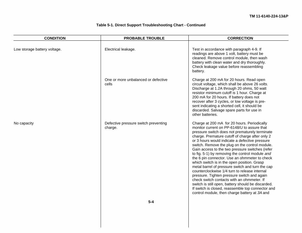
TM 11-6140-224-13&P
Table 5-1. Direct Support Troubleshooting Chart - Continued
CONDITION PROBABLE TROUBLE CORRECTION
Low storage battery voltage. Electrical leakage. Test in accordance with paragraph 4-9. Ifreadings are above 1 volt, battery must becleaned. Remove control module, then washbattery with clean water and dry thoroughly.Check leakage value before reassemblingbattery.
One or more unbalanced or defective Charge at 200 mA for 20 hours. Read opencells circuit voltage, which shall be above 26 volts.
Discharge at 1.2A through 20 ohms, 50 wattresistor minimum cutoff is 1 hour. Charge at200 mA for 20 hours. If battery does notrecover after 3 cycles, or low voltage is pre-sent indicating a shorted cell, it should bediscarded. Salvage spare parts for use inother batteries.
No capacity Defective pressure switch preventing Charge at 200 mA for 20 hours. Periodicallycharge. monitor current on PP-6148/U to assure that
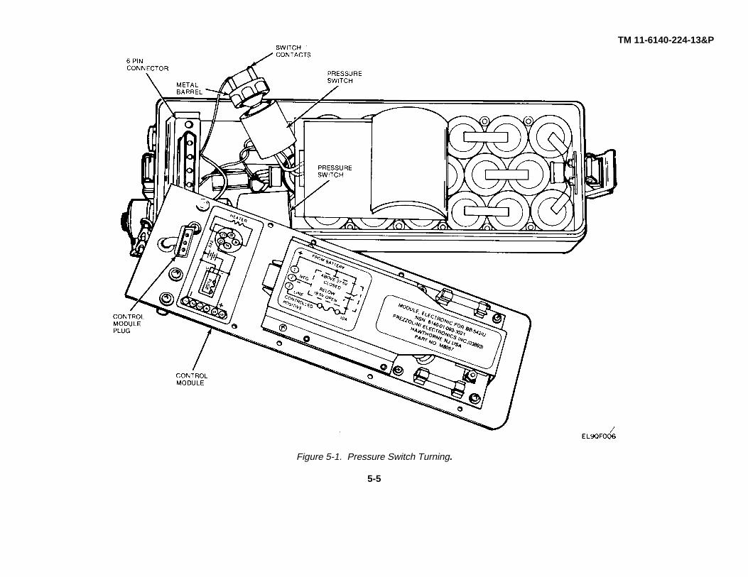
pressure switch does not prematurely terminatecharge. Premature cutoff of charge after only 2or 3 hours would indicate a defective pressureswitch. Remove the plug on the control module.Gain access to the two pressure switches (referto fig. 5-1) by removing the control module andthe 6 pin connector. Use an ohmmeter to checkwhich switch is in the open position. Graspmetal barrel of pressure switch and turn the capcounterclockwise 1/4 turn to release internalpressure. Tighten pressure switch and againcheck switch contacts with an ohmmeter. Ifswitch is still open, battery should be discarded.If switch is closed, reassemble top connector andcontrol module, then charge battery at 3A and
5-4
TM 11-6140-224-13&P
Figure 5-1. Pressure Switch Turning.
5-5

TM 11-6140-224-13&PTable 5-1. Direct Support Troubleshooting Chart - Continued
CONDITION PROBABLE TROUBLE CORRECTION
31 l 1V for 2 hours. The charge should be com-plete and the switch should reset at least onceduring the second hour of charge, otherwisereplace battery.
With battery at a temperature of 400F or less,No capacity after low Inoperative heater. use ohmmeter and measure resistance betweentemperature charge. Pins A and C of connector MS3112E-14-5S.
Reading should be 10 +1 ohm. A reading of 20ohms would indicate that one of the two heaterblankets are defective. Only the top heater isreplaceable. An open reading would indicate adefective thermal switch. Replace thermalswitch or use battery only at temperaturesabove 300F.
Loosen eight screws holding the control moduleOverheating on Shorted bypass diode. plate to battery. Diode is located under 6 pincharge connector. Check with TS-352B/U in ohmmeter
mode. A low resistance in both directions wouldindicate a defective diode. Replace diode ifshorted.
5-6

TM 11-6140-224-13&PAPPENDIX A
REFERENCES
DA Pam 310-1 Consolidated Index of Army Publications and Blank Forms.
DA Pam 738-750 The Army Maintenance Management System (TAMMS).
SB 11-573 Painting and Preservation of Supplies Available for Field Use for ElectronicCommand Equipment.
TB 43-0118 Field Instructions for Painting and Preserving Electronics Command EquipmentIncluding Camouflage Pattern Painting or Electrical Shelters.
TM 11-6115-470-10 Operator’s Manual, Direct Current Generator G-76/G (NSN 6115-01-082-8107),Direct Current Generator G-76/G(V)1, Direct Current Generator G-76/G(V)2.
TM 11-6130-356-12 Operator’s and Organizational Maintenance Manual Power Supply PP-6148/U(NSN 6130-01-062-3618).
TM 11-6140-203-14-1 Operator’s Organizational, Direct Support, General Support, MaintenanceManual: Aircraft and Nonaircraft Nickel-Cadmium Batteries (General).
TM 11-6625-366-10 Operator’s Manual for Multimeter TS-352B/U (NSN 6625-00-553-0142).
TM 750-244-2 Procedures for Destruction of Electronics Materiel to Prevent Enemy Use(Electronics Command).
A-1/(A-2 blank)

TM 11-6140-224-13&PAPPENDIX B
MAINTENANCE ALLOCATION
Section I. INTRODUCTION
B-1. GeneralThis appendix provides a summary of the maintenance operations for BB-542/U. It authorizes categories of maintenancefor specific maintenance functions on repairable items and components and the tools and equipment required to performeach function. This appendix may be used as an aid in planning maintenance operations.
B.2. Maintenance FunctionMaintenance functions will be limited to and defined as follows:
a. Inspect. To determine the serviceability of an item by comparing its physical, mechanical, and/or electricalcharacteristics with established standards through examination.
b. Test. To verify serviceability and to detect incipient failure by measuring the mechanical or electricalcharacteristics of an item and comparing those characteristics with prescribed standards.
c. Service. Operations required periodically to keep an item in proper operating condition, i.e., to clean(decontaminate), to preserve, to drain, to paint, or to replenish fuel, lubricants, hydraulic fluids, or compressed air supplies.
d. Adjust. To maintain, within prescribed limits, by bringing into proper or exact position, or by setting the operatingcharacteristics to the specified parameters.
e. Align. To adjust specified variable elements of an item to bring about optimum or desired performance.
f. Calibrate. To determine and cause corrections to be made or to be adjusted on instruments or test measuring anddiagnostic equipment used in precision measurement. Consists of comparisons of two Instruments, one of which is acertified standard of known accuracy, to detect and adjust any discrepancy in the accuracy of the instrument beingcompared.
g. Install. The act of emplacing, seating, or fixing into position an item, part, module (component or assembly) in amanner to allow the proper functioning of the equipment of system.
h. Replace. The act of substituting a serviceable like type part, subassembly, or module (component or assembly) foran unserviceable counterpart.
i. Repair. The application of maintenance services (inspect, test, service, adjust, align, calibrate. replace) or othermaintenance actions (welding, grinding, riveting. straightening, facing. remachining. or resurfacing) to restore serviceabilityto an item by correcting specific damage, fault. malfunction. or failure in a part, subassembly. module (component orassembly), end item, or system.
j. Overhaul. That maintenance effort (service/action) necessary to restore an item to a completely ser-viceable/operational condition as prescribed by maintenance standards (i.e., DMWR) in appropriate technical publications.Overhaul is normally the highest degree of maintenance performed by the Army. Overhaul does not normally return anitem to like new condition.
k. Rebuild. Consists of those services/actions necessary for the restoration of unserviceable equipment to a like newcondition in accordance with original manufacturing standards. Rebuild is the highest degree of materiel maintenanceapplied to Army equipment. The rebuild operation includes the act of turning to zero those age measurements (hours,miles, etc.) considered in classifying Army equipments/components.
B-3. Column Entries
a. Column 1, Group Number. Column 1 lists group numbers, the purpose of which is to identify components,assemblies, and modules with the next higher assembly.
B-1
TM 11-6140-224-13&P
b. Column 2, Component/Assembly. Column 2 contains the noun names of components, assemblies subassemblies,and modules for which maintenance is authorized.
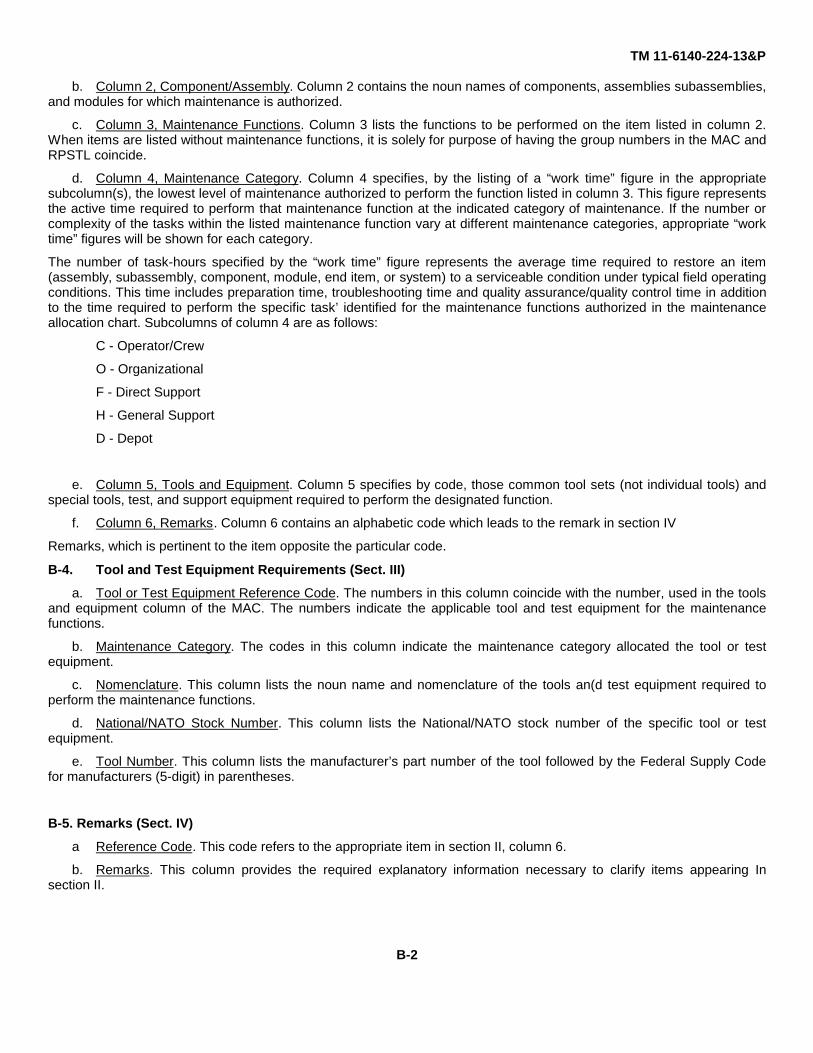
c. Column 3, Maintenance Functions. Column 3 lists the functions to be performed on the item listed in column 2.When items are listed without maintenance functions, it is solely for purpose of having the group numbers in the MAC andRPSTL coincide.
d. Column 4, Maintenance Category. Column 4 specifies, by the listing of a “work time” figure in the appropriatesubcolumn(s), the lowest level of maintenance authorized to perform the function listed in column 3. This figure representsthe active time required to perform that maintenance function at the indicated category of maintenance. If the number orcomplexity of the tasks within the listed maintenance function vary at different maintenance categories, appropriate “worktime” figures will be shown for each category.
The number of task-hours specified by the “work time” figure represents the average time required to restore an item(assembly, subassembly, component, module, end item, or system) to a serviceable condition under typical field operatingconditions. This time includes preparation time, troubleshooting time and quality assurance/quality control time in additionto the time required to perform the specific task’ identified for the maintenance functions authorized in the maintenanceallocation chart. Subcolumns of column 4 are as follows:
C - Operator/Crew
O - Organizational
F - Direct Support
H - General Support
D - Depot
e. Column 5, Tools and Equipment. Column 5 specifies by code, those common tool sets (not individual tools) andspecial tools, test, and support equipment required to perform the designated function.
f. Column 6, Remarks. Column 6 contains an alphabetic code which leads to the remark in section IV
Remarks, which is pertinent to the item opposite the particular code.
B-4. Tool and Test Equipment Requirements (Sect. III)
a. Tool or Test Equipment Reference Code. The numbers in this column coincide with the number, used in the toolsand equipment column of the MAC. The numbers indicate the applicable tool and test equipment for the maintenancefunctions.
b. Maintenance Category. The codes in this column indicate the maintenance category allocated the tool or testequipment.
c. Nomenclature. This column lists the noun name and nomenclature of the tools an(d test equipment required toperform the maintenance functions.
d. National/NATO Stock Number. This column lists the National/NATO stock number of the specific tool or testequipment.
e. Tool Number. This column lists the manufacturer’s part number of the tool followed by the Federal Supply Codefor manufacturers (5-digit) in parentheses.
B-5. Remarks (Sect. IV)
a Reference Code. This code refers to the appropriate item in section II, column 6.
b. Remarks. This column provides the required explanatory information necessary to clarify items appearing Insection II.
B-2

TM 11-6140-224-13&P
Section II. MAINTENANCE ALLOCATION CHARTFOR
BATTERY, STORAGEBB-542/U
(1) (2) (3) (4) (5) (6)TOOLS
GROUP COMPONENT/ASSEMBLY MAINTENANCE MAINTENANCE CATEGORY ANDNUMBER FUNCTION C O F H D EQPT REMARKS
00 BATTERY, STORAGEBB-542/U INSPECT 0.1 A(NICKEL-CADMIUM SERVICE 0.5 3 CSEALED) TEST 0.1 1, 2, 7 B
REPLACE 01 D
INSPECT 0.5 ATEST 1.0 1,2,4 E
thru 7
REPLACE 0.2 3 FREPAIR 1.0 3 G
B-3
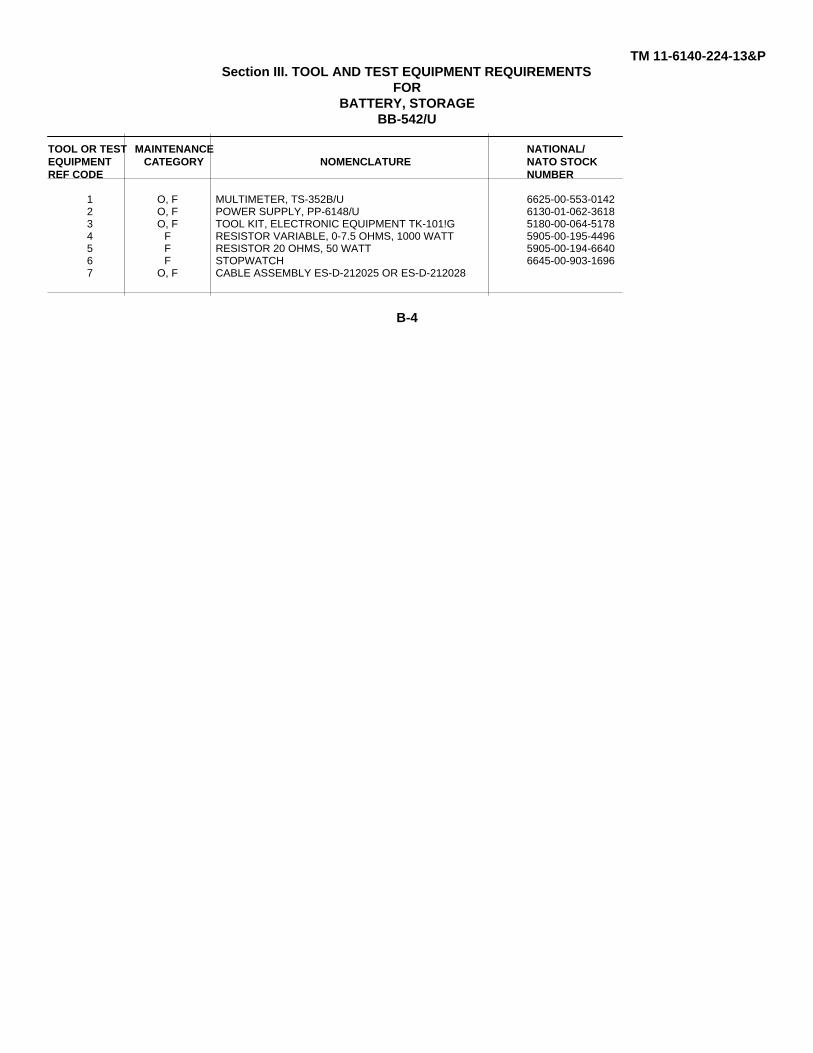
TM 11-6140-224-13&PSection III. TOOL AND TEST EQUIPMENT REQUIREMENTS
FORBATTERY, STORAGE
BB-542/U
TOOL OR TEST MAINTENANCE NATIONAL/EQUIPMENT CATEGORY NOMENCLATURE NATO STOCKREF CODE NUMBER
1 O, F MULTIMETER, TS-352B/U 6625-00-553-01422 O, F POWER SUPPLY, PP-6148/U 6130-01-062-36183 O, F TOOL KIT, ELECTRONIC EQUIPMENT TK-101!G 5180-00-064-51784 F RESISTOR VARIABLE, 0-7.5 OHMS, 1000 WATT 5905-00-195-44965 F RESISTOR 20 OHMS, 50 WATT 5905-00-194-66406 F STOPWATCH 6645-00-903-16967 O, F CABLE ASSEMBLY ES-D-212025 OR ES-D-212028
B-4
TM 11-6140-224-13&P
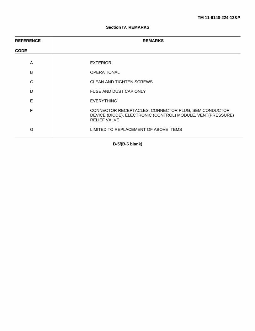
Section IV. REMARKS
REFERENCE REMARKS
CODE
A EXTERIOR
B OPERATIONAL
C CLEAN AND TIGHTEN SCREWS
D FUSE AND DUST CAP ONLY
E EVERYTHING
F CONNECTOR RECEPTACLES, CONNECTOR PLUG, SEMICONDUCTORDEVICE (DIODE), ELECTRONIC (CONTROL) MODULE, VENT(PRESSURE)RELIEF VALVE
G LIMITED TO REPLACEMENT OF ABOVE ITEMS
B-5/(B-6 blank)

TM 11-6140-224-13&P
APPENDIX CREPAIR PARTS LIST
SECTION I. IntroductionC-1. ScopeThis manual lists and authorizes spares and repair parts; special tools; special test, measurement, and diagnosticequipment (TMDE); and other special support equipment required for performance of organizational and direct supportmaintenance of the BB-542/U. It authorizes the requisitioning, issue, and disposition of spares, repair parts and specialtools as indicated by the source, maintenance and recoverability (SMR) codes.
C-2. GeneralThis Repair Parts and Special Tools List is divided into the following sections:
a. Section II - Repair Parts List. A list of spares and repair parts authorized by this RPSTL for use in theperformance of maintenance. The list also includes parts which must be removed for replacement of the authorized parts.Parts lists are composed of functional groups in ascending numeric sequence, with the parts in each group listed inascending item number sequence. Figure numbers are listed directly beneath the group header.
b. Section III - Special Tools List. Not applicable.
c. Section IV - National Stock Number and Part Number Index. A list, in National item identification number(NIIN) sequence, of all National stock numbered items appearing in the listing, followed by a list in alphameric sequence ofall part numbers appearing in the listings. National stock numbers and part numbers are cross-referenced to eachillustration figure and item number appearance. C-3. Explanation of Columns (Section II and III)
a. Item No. (Column (1)). Indicates the number used to identify items called out in the illustration.
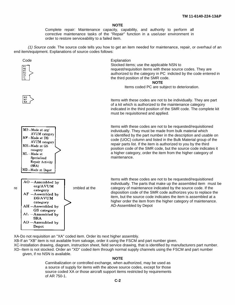
b. SMR Code (Column (2)). The source, maintenance, and recoverability (SMR) code is a five-position codecontaining supply/requisitioning information, maintenance category authorization criteria, and disposition instruction, asshown in the following breakout:
C-1
TM 11-6140-224-13&P
NOTEComplete repair: Maintenance capacity, capability, and authority to perform allcorrective maintenance tasks of the "Repair" function in a use/user environment inorder to restore serviceability to a failed item.
(1) Source code. The source code tells you how to get an item needed for maintenance, repair, or overhaul of anend item/equipment. Explanations of source codes follows:
Code ExplanationStocked items; use the applicable NSN to request/requisition items with these source codes. They are authorized to the category in PC indicted by the code entered in the third position of the SMR code.
NOTEItems coded PC are subject to deterioration.
Items with these codes are not to be individually. They are part of a kit which is authorized to the maintenance category indicated in the third position of the SMR code. The complete kit must be requisitioned and applied.
Items with these codes are not to be requested/requisitionedindividually. They must be made from bulk material which is identified by the part number in the description and usable on code (UOC) column and listed in the Bulk Material group of the repair parts list. If the item is authorized to you by the third position code of the SMR code, but the source code indicates it a higher category, order the item from the higher category of maintenance.
Items with these codes are not to be requested/requisitioned individually. The parts that make up the assembled item must be
requisitioned or fabricated and assembled at the category of maintenance indicated by the source code. If the disposition code of the SMR code authorizes you to replace the item, but the source code indicates the item is assembled at a higher order the item from the higher category of maintenance.AD-Assembled by Depot
XA-Do not requisition an "XA" coded item. Order its next higher assembly.XB-If an "XB" item is not available from salvage, order it using the FSCM and part number given.XC-Installation drawing, diagram, instruction sheet, field service drawing, that is identified by manufacturers part number.XD--Item is not stocked. Order an "XD" coded item through normal supply channels using the FSCM and part number
given, if no NSN is available.NOTE
Cannibalization or controlled exchange, when authorized, may be used asa source of supply for items with the above source codes, except for thosesource coded XA or those aircraft support items restricted by requirementsof AR 750-1.
C-2
TM 11-6140-224-13&P
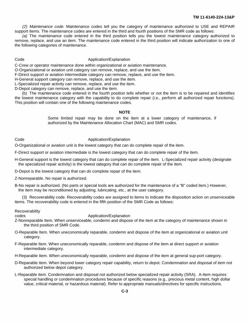
(2) Maintenance code. Maintenance codes tell you the category of maintenance authorized to USE and REPAIRsupport items. The maintenance codes are entered in the third and fourth positions of the SMR code as follows:
(a) The maintenance code entered in the third position tells you the lowest maintenance category authorized toremove, replace, and use an item. The maintenance code entered in the third position will indicate authorization to one ofthe following categories of maintenance.
Code Application/Explanation
C-Crew or operator maintenance done within organizational or aviation maintenance.O-Organizational or aviation unit category can remove, replace, and use the item.F-Direct support or aviation intermediate category can remove, replace, and use the item.H-General support category can remove, replace, and use the item.L-Specialized repair activity can remove, replace, and use the item.D-Depot category can remove, replace, and use the item.
(b) The maintenance code entered in the fourth position tells whether or not the item is to be repaired and identifiesthe lowest maintenance category with the capability to do complete repair (i.e., perform all authorized repair functions).This position will contain one of the following maintenance codes.
NOTESome limited repair may be done on the item at a lower category of maintenance, ifauthorized by the Maintenance Allocation Chart (MAC) and SMR codes.
Code Application/Explanation
O-Organizational or aviation unit is the lowest category that can do complete repair of the item.
F-Direct support or aviation intermediate is the lowest category that can do complete repair of the item.
H-General support is the lowest category that can do complete repair of the item. L-Specialized repair activity (designate the specialized repair activity) is the lowest category that can do complete repair of the item.
D-Depot is the lowest category that can do complete repair of the item.
Z-Nonreparable. No repair is authorized.
B-No repair is authorized. (No parts or special tools are authorized for the maintenance of a “B” coded item.) However, the item may be reconditioned by adjusting, lubricating, etc., at the user category.
(3) Recoverability code. Recoverability codes are assigned to items to indicate the disposition action on unserviceableitems. The recoverability code is entered in the fifth position of the SMR Code as follows:
Recoverabilitycodes Application/ExplanationZ-Nonreparable Item. When unserviceable, condemn and dispose of the item at the category of maintenance shown in
the third position of SMR Code.
O-Reparable Item. When uneconomically reparable, condemn and dispose of the item at organizational or aviation unit category.
F-Reparable Item. When uneconomically reparable, condemn and dispose of the item at direct support or aviation intermediate category.
H-Reparable Item. When uneconomically reparable, condemn and dispose of the item at general sup-port category.
D-Reparable item. When beyond lower category repair capability, return to depot. Condemnation and disposal of item not authorized below depot category.
L-Reparable item. Condemnation and disposal not authorized below specialized repair activity (SRA). A-Item requires special handling or condemnation procedures because of specific reasons (e.g., precious metal content, high dollar value, critical material, or hazardous material). Refer to appropriate manuals/directives for specific instructions.
C-3

TM 11-6140-224-13&P
c. FSCM (Column (3)). The Federal Supply Code for Manufacturer (FSCM) is a 5-digit numeric code which is used toidentify the manufacturer, distributor, or Government agency, etc., that supplies the item.
d. Part Number (Column (4)). Indicates the primary number used by the manufacturer (individual, company, firm,corporation, or Government activity), which controls the design and characteristics of the item by means of its engineeringdrawings, specifications, standards, and inspection requirements to identify an item or range of items.
NOTEWhen you use a NSN to requisition an item, the item you receive may have a different partnumber from the part ordered.
e. Description and Usable on Code (UOC) (Column (5)). This column includes the following information.(1) The Federal item name and, when required, a minimum description to identify the item.(2) The statement “END OF FIGURE” appears just below the last item description in Column (5) for a given
figure in both section II and section III.f. Qty. (Column (6)). Indicates the quantity of the item used in the breakout shown on the illustration figure, which is
prepared for a functional group, subfunctional group, or an assembly. A “V” appearing in this column in lieu of a quantityindicates that the quantity is variable and the quantity may vary from application to application.
C-4. Explanation of Columns (Section IV)
a. National Stock Number (NSN) Index.(1) Stock number column. This column lists the NSN by National item identification number (NIIN) se-quence.
The NIIN consists of the last nine digits of the NSN. When using this column to locate an item, Ignore the first four digits ofthe NSN. When requisitioning items use the complete NSN (13 digits).
(2) Fig. column. This column lists the number of the figure where the item is identified/located. The il-lustrations are In numerical sequence in sections II and III.
(3) Item column. The item number identifies the item associated with the figure listed in the adjacent Fig.column. This item is also identified by the NSN listed on the same line.
b. Part Number Index. Part numbers in this index are listed by part number in ascending alphameric sequence.(1) FSCM column. This column lists the Federal supply code for manufacturer (FSCM).(2) Part number column. This column indicates the part number assigned to the item.(3) Stock number column. This column lists the National stock number for the associated part number and
manufacturer identified in the part number and FSCM columns to the left.(4) Fig. column. This column lists the number of the figure where the item is identified/located in sections II
and III.(5) Item column. The item number is that number assigned to the item as it appears in the figure referenced
in the adjacent figure number column. C-5. Special Information National stock numbers (NSN’s) that are missing from Psource coded items have been applied for and will be added to this TM by future change/revision when they are entered inthe Army Master Data File (AMDF). Until the NSN’s are established and published, submit exception requisitions to:Commander, US Army Communications-Electronics Command and Fort Monmouth, ATTN: AMSEL-MM, Fort Mon-mouth,NJ 07703-5006 for the part required to support your equipment.
C-6. How to Locate Repair Parts
a. When National stock number or part number is not known.(1) First. Using the table of contents, determine the assembly group or subassembly group to which the item
belongs. This is necessary since figures are prepared for assembly groups and subassembly groups, and listings aredivided into the same groups.
(2) Second. Find the figure covering the assembly group or subassembly group to which the item belongs.(3) Third. Identify the item on the figure and note the item number.(4) Fourth. Refer to the Repair Parts List for the figure to find the part number for the item number noted on
the figure.(5) Fifth. Refer to the Part Number Index to find the NSN, if assigned.
C-4

TM 11-6140-224-13&P
b. When National stock number or part number is known.(1) First. Using the index of National stock numbers and part numbers, find the pertinent National stock
number or part number. The NSN index is in National item identification number (NIIN) sequence (para 4a(1)). The partnumbers in the part number index are listed in ascending alphameric sequence (para j). Both indexes cross-reference youto the illustration figure and item number of the item you are looking for.
(2) Second. After finding the figure and item number, verify that the item is the one you’re looking for, thenlocate the item number in the repair parts list for the figure.
7. AbbreviationsNot applicable.
C-5
TM 11-6140-224-13&P
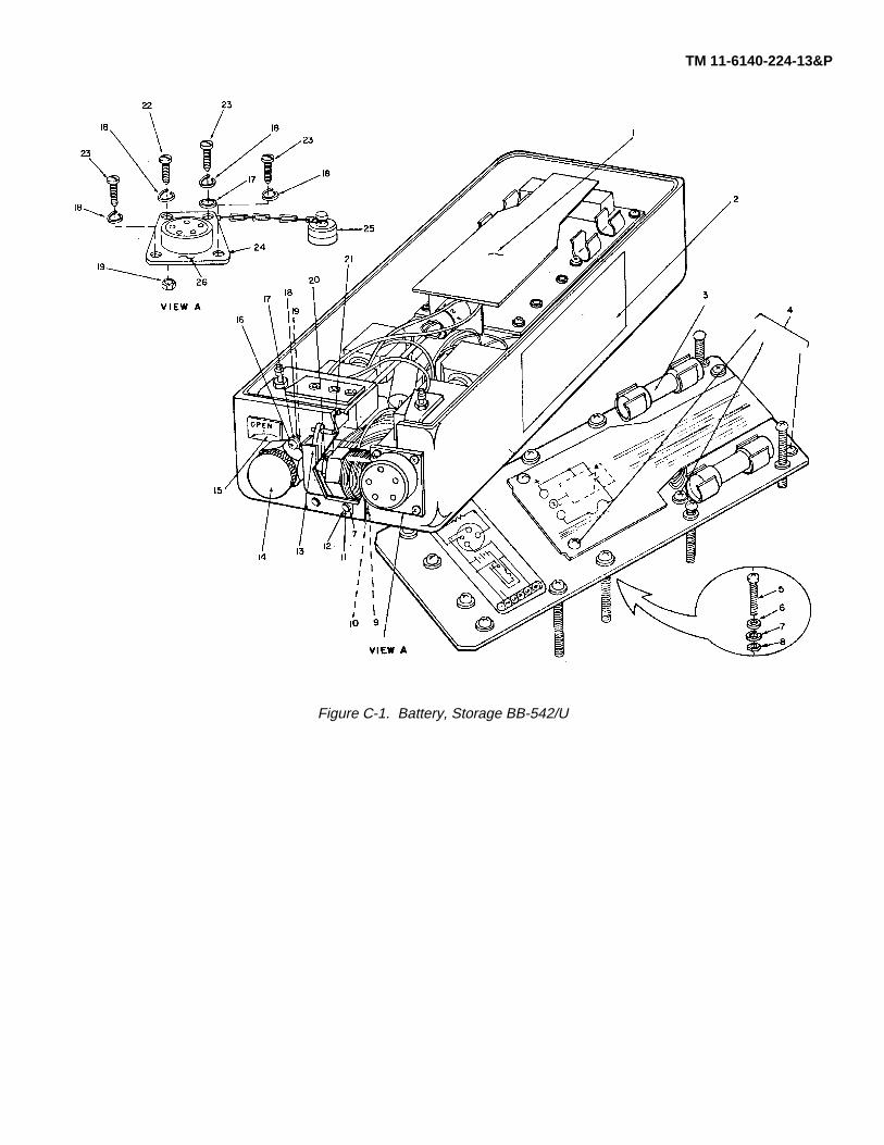
Figure C-1. Battery, Storage BB-542/U

SECTION II TM 11-6140-224-13&P(1) (2) (3) (4) (5) (6)
ITEM SMR PARTNO CODE CAGEC NUMBER DESCRIPTION AND USABLE ON CODES (UOC) QTY
GROUP 00 BATTERY, STORAGE BB-542/UFIG. C-1
1 PAFZZ 03893 M8057 ELECTRONIC .MODILF .............................................. 12 XBFZZ 57945 C5075607 NAMEPLATE ............................................................... 13 DAOZZ 81349 F03A250VIOAS FUSE,CARTRIDGE ..................................................... 24 PAFZZ 96906 MS-51957-13 SCREW,MACHINE ...................................................... 65 PAFZZ 96906 MS51957-37 SCREW,MACHINE ...................................................... 86 PAFZZ 96906 MS-15795-805 WASHER,FLAT............................................................ 87 PAFZZ 96906 MS-35338-136 WASHFR,LOCK........................................................... 128 XBFZZ 57945 C5075639 SPACER....................................................................... 89 XBFZZ 57945 C5075637 WASHER MICA ........................................................... 1
10 PAFZZ 30131 IN5828 SEMICONDUCTOR DEVIC ......................................... 111 PAFZZ 96906 MS-51957-30B SCPEW,MACHINE ...................................................... 412 PAFZZ 18876 9052346 NUT,PLAIN,HEXAGON ............................................... 413 XBFZZ 57945 C5075619 LATCH.......................................................................... 214 PAFZZ 98021 I90ARL VALVE,PRESSURE RELI............................................ 115 XBFZZ 57945 C5075609 ARROW LABEL ........................................................... 116 PAFZZ 96906 MS51957-16 SCREW,MACHINE ...................................................... 117 PAFZZ 96906 MS-15795-803 WASHER,FLAT............................................................ 618 PAFZZ 96906 MS-35338-135 WASHER,LOCK .......................................................... 1119 XBFZZ 80525 NAS671-C4 NUT,HEX SS#4-40 ...................................................... 220 XBRZZ 57945 C5075638 WASHER SHOULDER ................................................ 121 XBFZZ 80525 NAS671-C10 NUT-HEX i10 ............................................................... 122 PARZZ 96906 MS-51957-17 SCREW,MACHINE ...................................................... 123 PAFZZ 96906 MS-51957-14 SCREW,MACHINE ...................................................... 324 XBFZZ 57945 C5075628 RASKET PUBBER ....................................................... 125 XBFZZ 57945 C5075636 DUST COVER ............................................................. 126 PAFZZ 96906 MS-3112E-14-5S CONNECTCP,RECEPTACL........................................ 1
END OF FIGURE
C-1-1

SECTION IV TM 11-6140-224-13&PNATIONAL STOCK NUMBER INDEX
NATIONAL STOCK NUMBER AND PART NUMBER INDEXSTOCK NUMBER FIG. ITEM STOCK NUMBER FIG. ITEM
5305-00-054-5647 C-1 45305-00-054-5648 C-1 235335-00-054-5650 C-1 165305-00-354-5651 C-1 225305-00-054-6661 C-1 55920-00-243-3787 C-1 35305-00-469-5382 C-1 115310-00-595-6211 C-1 175310-00-616-8660 C-1 125310-00-722-5999 C-1 65935-00-893-7952 C-1 264820-00-908-1571 C-1 145310-00-929-6395 C-1 75310-00-933-8118 C-1 185961-01-016-1485 C-1 10
C-I-1

SECTION IV TM 11-6140-224-13&PNATIONAL STOCK NUMBER AND PART NUMBER INDEX
PART NUMBER INDEX
FSCM PART NUMBER STOCK NUMBER FIG. ITEM
57945 C5075607 C-1 257945 C5075609 C-1 1557945 C5075619 C-1 1357945 C5075628 C-1 2457945 C5075636 C-1 2557945 C5075637 C-1 957945 C5075638 C-1 2057945 C5075639 C-1 881349 F03A250VIOAS 5920-00-243-3787 C-1 396906 MS-15795-803 5310-00-595-6211 C-1 1796906 MS-15795-805 5310-00-722-5998 C-1 696906 MS-311?E-14-5S 5935-00-893-7952 C-1 2696906 MS-35338-135 5310-00-933-8118 C-1 1396906 MS-35338-136 5310-00-929-6395 C-1 796906 MS-51957-13 5305-00-054-5647 C-1 496906 MS-51957-14 5305-90-054-5648 C-1 2396906 MS-51957-17 5305-00-054-5651 C-1 2296906 MS-51957-30B 5305-00-469-539? C-1 1196906 MS51957-16 5305-00-054-5650 C-1 1696906 MS51957-37 5305-00-054-6661 C-1 503893 M8057 C-1 180525 NAS671-C10 C-1 2180525 NAS671-C4 C-1 1980131 1N5828 5961-01-016-8485 C-1 1098021 190ARL 4820-00-908-1571 C-1 1418876 9052346 5310-00-616-8660 C-I 12
C-I-2

TM 11-6140-224-13&PBy Order of the Secretary of the Army:
JOHN A. WICKHAM JR.General, United States Army
Official: Chief of Staff
DONALD J. DELANDROBrigadiar General, United States Army
The Adjutant General
DISTRIBUTION:To be distributed in accordance with DA Form 12-36A literature requirements for Nickel-Cadmium Batteries.
*U.S. GOVERMENT PRINTING OFFICE 1985 505-044/20047

PIN: 057355
This fine document...
Was brought to you by me:
Liberated Manuals -- free army and government manuals
Why do I do it? I am tired of sleazy CD-ROM sellers, who take publicly available information, slap “watermarks” and other junk on it, and sell it. Those masters of search engine manipulation make sure that their sites that sell free information, come up first in search engines. They did not create it... They did not even scan it... Why should they get your money? Why are not letting you give those free manuals to your friends?
I am setting this document FREE. This document was made by the US Government and is NOT protected by Copyright. Feel free to share, republish, sell and so on.
I am not asking you for donations, fees or handouts. If you can, please provide a link to liberatedmanuals.com, so that free manuals come up first in search engines:
<A HREF=http://www.liberatedmanuals.com/>Free Military and Government Manuals</A>
– SincerelyIgor Chudovhttp://igor.chudov.com/
– Chicago Machinery Movers