tm 11-6625-2638-30 · components assembly mx-9623/aas-32 (electronic assembly). 1-2. maintenance...
TRANSCRIPT

TM 11-6625-2638-30
DIRECT SUPPORTMAINTENANCE MANUAL
AIRBORNE LASER TRACKERTEST SET AN/AAM-55
(NSN 5860-01-070-3842)
HEADQUARTERS, DEPARTMENT OF THE ARMY
4 JUNE 1984


WARNING
TM 11-6625-2638-30
ELSTN046
Ensure 115 vdc and 28 vdc power source is off before connecting powercables. Contact with 115 vac may cause injury or death.
A /(B blank)

Technical Manual
No. 11-6625-2638-30
DIRECT
AIRBORNE
TM 11-6625-2638-30
HEADQUARTERSDEPARTMENT OF THE ARMY
Washington, DC, 4 June 1984
SUPPORT MAINTENANCE MANUAL
LASER TRACKER TEST SET AN/AAM-55
(NSN 5860-01-070-3842)
REPORTING ERRORS AND RECOMMENDING IMPROVEMENTS
You can help improve this manual. If you find any mistakes or if you know of a way to improve the procedures, please let us know.Mail your letter, DA Form 2028 (Recommended Changes to Publications and Blank Forms), or DA Form 2028-2 located in the backof this manual direct to: Commander, US Army Communications - Electronics Command and Fort Monmouth, ATTN: DRSEL-
ME-MP, Fort Monmouth, New Jersey 07703. A reply will be furnished to you.
Paragraph
CHAPTER 1 INTRODUCTIONSection I General Information
Scope . . . . . . . . . . . . . . . . . . . . . . . . . . . . . . . . . . . . . . . . . . . . . . . . . . . . . . . . . . . . . . . . . . . . . . . . . . . . . . . . . .Maintenance Forms, Records and Reports . . . . . . . . . . . . . . . . . . . . . . . . . . . . . . . . .Destruction of Army Materiel to Prevent Enemy Use . . . . . . . . . . . . . . . . . . . . .Preparation for Storage or Shipment . . . . . . . . . . . . . . . . . . . . . . . . . . . . . . . . . . . . . . . . . .Nomenclature Cross-Reference List . . . . . . . . . . . . . . . . . . . . . . . . . . . . . . . . . . . . . . . . . . .Reporting Equipment Improvement Recommendations (EIR) . . . . . . . . . .
II Equipment Description and Data . . . . . . . . . . . . . . . . . . . . . . . . . . . . . . . . . . . . . . . . . . . . . . .Equipment Characteristics, Features and Capabilities . . . . . . . . . . . . . . . . . . .Location and Description of Major Components . . . . . . . . . . . . . . . . . . . . . . . . . . .Equipment Data . . . . . . . . . . . . . . . . . . . . . . . . . . . . . . . . . . . . . . . . . . . . . . . . . . . . . . . . . . . . . . . . . . . . .
Ill Principles of Operation . . . . . . . . . . . . . . . . . . . . . . . . . . . . . . . . . . . . . . . . . . . . . . . . . . . . . . . . . . . .General Information . . . . . . . . . . . . . . . . . . . . . . . . . . . . . . . . . . . . . . . . . . . . . . . . . . . . . . . . . . . . . . . .Receiver Cage Test Functional Description . . . . . . . . . . . . . . . . . . . . . . . . . . . . . . . . .Receiver Scan Test Functional Description . . . . . . . . . . . . . . . . . . . . . . . . . . . . . . . . .Receiver LED Test Functional Description . . . . . . . . . . . . . . . . . . . . . . . . . . . . . . . . . .Electronic Assembly Power Supply Test Functional Description . . . . . .Electronic Assembly Cage (Standby) Test Functional Description ..,.Electronic Assembly Scan Test Functional Description . . . . . . . . . . . . . . . . . .Electronic Assembly Tracking Test Functional Description . . . . . . . . . . . . .Electronic Assembly Power BITE Test Functional Description . . . . . . . . .
1-11-21-31-41-51-6
1-71-81-9
1-101-111-121-131-141-151-161-171-18
Page
1-11-11-11-11-11-21-21-2
1-21-21-31-4
1-41-41-51-61-71-81-9
1-101-121-14
i

TM 11-6625-2638-30
CHAPTER 2Section I
II
III
IV
V
APPENDIX A
GLOSSARY
MAINTENANCE INSTRUCTIONSRepair Parts, Special Tools; Test, Measurement, and DiagnosticEquipment (TMDE); and Support Equipment . . . . . . . . . . . . . . . . . . . . . . . . . . . . . . .Common Tools and Equipment . . . . . . . . . . . . . . . . . . . . . . . . . . . . . . . . . . . . . . . . . . . . . . . . .Special Tools, TMDE, and Support Equipment . . . . . . . . . . . . . . . . . . . . . . . . . . . .Repair Parts . . . . . . . . . . . . . . . . . . . . . . . . . . . . . . . . . . . . . . . . . . . . . . . . . . . . . . . . . . . . . . . . . . . . . . . . . .
Service Upon Receipt . . . . . . . . . . . . . . . . . . . . . . . . . . . . . . . . . . . . . . . . . . . . . . . . . . . . . . . . . . . . .Packing/Unpacking . . . . . . . . . . . . . . . . . . . . . . . . . . . . . . . . . . . . . . . . . . . . . . . . . . . . . . . . . . . . . . . . .Checking Unpacked ALT Test Set . . . . . . . . . . . . . . . . . . . . . . . . . . . . . . . . . . . . . . . . . . . . .
Troubleshooting Procedure . . . . . . . . . . . . . . . . . . . . . . . . . .... . . . . . . ... . . . . . . . . . . . . .Test Set Troubleshooting . . . . . . . . . . . . . . . . . . . . . . . . . . . . . . . . . . . . . . . . . . . . . . . . . . . . . . . . .Tools and Equipment . . . . . . . . . . . . . . . . . . . . . . . . . . . . . . . . . . . . . . . . . . . . . . . . . . . . . . . . . . . . . .Controls and Indicators . . . . . . . . . . . . . . . . . . . . . . . . . . . . . . . . . . . . . . . . . . . . . . . . . . . . . . . . . . .Connector Pin Locations . . . . . . . . . . . . . . . . . . . . . . . . . . . . . . . . . . . . . . . . . . . . . . . . . . . . . . . . . .Schematics and Wire Lists . . . . . . . . . . . . . . . . . . . . . . . . . . . . . . . . . . . . . . . . . . . . . . . . . . . . . . .
Maintenance Procedures . . . . . . . . . . . . . . . . . . . . . . . . . . . . . . . . . . . . . . . . . . . . . . . . . . . . . . . . .Checking Continuity - General Instructions . . . . . . . . . . . . . . . . . . . . . . . . . . . . . . . . . .R196 Adjustment Procedure . . . . . . . . . . . . . . . . . ... . . . . . . . . . . . . . . . . . . . . . . . . . . . . . . . .R197 Adjustment Procedure . . . . . . . . . . . . . . . . . . . . . . . . . . . . . . . . . . . . . . . . . . . . . . . . . . . . .Removing Test Set from Case . . . . . . . . . . . . . . . . . . . . . . . . . . . . . . . . . . . . . . . . . . . . . . . . . .Installing Test Set into Case . . . . . . . . . . . . . . . . . . . . . . . . . . . . . . . . . . . . . . . . . . . . . ... . .Removing Circuit Card . . . . . . . . . . . . . . . . . . . . . . . . . . . . . . . . . . . . . . . . . . . . . . . . . . . . . . . . . . . .Installing Circuit Card . . . . . . . . . . . . . . . . . . . . . . . . . . . . . . . . . . . . . . . . . . . . . . . . . . . . . . . ... . .Removing Power Supply . . . . . . . . . . . . . . . . . . . . . . . . . . . . . . . . . . . . . . . . . . . . . . . . . . . . . . . . .Installing Power Supply . . . . . . . . . . . . . . . . . . . . . . . . . . . . . . . . . . . . . . . . . . . . . . . . . . . . . . . . .Switch Replacement . . . . . . . . . . . . . . . . . . . . . . . . . . . . . . . . . . . . . . . . . . . . . . . . . . . . . . . . . .. . . .Lamp Holder Replacement . . . . . . . . . . . . . . . . . . . . . . . . . . . . . . . . . . . . . . . . . . . . . . . . . . . . . . .Fuse Holder Replacement . . . . . . . . . . . . . . . . . . . . . . . . . . . . . . . . . . . . . . . . . . . . . . . . . . . . . . .Test Jack Replacement . . . . . . . . . . . . . . . . . . . . . . . . . . . . . . . . . . . . . . . . . . . . . . . . . . . . . . . . . . .
Preparation for Storage or Shipment . . . . . . . . . . . . . . . . . . . . . . . . . . . . . . . . . . . . . . . . . .Preparing Test Set for Storage or Shipment . . . . . . . . . . . . . . . . . . . . . . . . . . . . . . . .Packing the Test Set . . . . . . . . . . . . . . . . . . . . . . . . . . . . . . . . . . . . . . . . . . . ... . . . . . . . . . . . . . .Packing the Test Stand . . . . . . . . . . . . . . . . . . . . . . . . . . . . . . . . . . . . . . . . . . . . . . . . . . . . . . . . . . .
REFERENCES . . . . . . . . . . . . . . . . . . . . . . . . . . . . . . . . . . . . . . . . . . . . . . . . . . . . . . . . . . . . . . . . . . . ..
2-12-22-3
2-42-5
2-72-82-9
2-102-11
2-122-132-142-152-162-172-182-192-202-212-222-232-24
2-252-262-27
Page
2-1
2-12-12-12-1
2-12-12-1
2-22-22-22-22-22-2
2-292-292-292-302-302-312-312-312-342-342-352-362-372-38
2-872-872-872-87
A-1
Glossary 1
Paragraph
i i

TM 11-6625-2638-30
LIST OF ILLUSTRATIONS
FigureNumber
1-11-21-31-41-51-61-71-81-9
1-10
2-12-22-32-42-52-62-7
FO-1FO-2FO-3
Title Page
Airborne Laser Tracker Test Set AN/AAM-55 . . . . . . . . . . . . . . . . . . . . . . . . . . . . . . . . . . . . . . . . . . . . . . . . . . . . . . . . . . . . . 1-1ALT Major Components . . . . . . . . . . . . . . . . . . . . . . . . . . . . . . . . . . . . . . . . . . . . . . . . . . . . . . . . . . . . . . . . . . . . . . . . . . . . . . . . . . . . . . . . . 1-3Receiver Cage Test Block Diagram . . . . . . . . . . . . . . . . . . . . . . . . . . . . . . . . . . . . . . . . . . . . . . . . . . . . . . . . . . . . . . . . . . . . . . . . . . 1-5Receiver Scan Test Block Diagram . . . . . . . . . . . . . . . . . . . . . . . . . . . . . . . . . . . . . . . . . . . . . . . . . . . . . . . . . . . . . . . . . . . . . . . . . . 1-6Receiver LED Test Block Diagram . . . . . . . . . . . . . . . . . . . . . . . . . . . . . . . . . . . . . . . . . . . . . . . . . . . . . . . . . . . . . . . . . . . . . . . . . . . 1-7Electronic Assembly Power Supply Test Block Diagram . . . . . . . . . . . . . . . . . . . . . . . . . . . . . . . . . . . . . . . . . . . . . . . 1-8Electronic Assembly Cage Test Block Diagram . . . . . . . . . . . . . . . . . . . . . . . . . . . . . . . . . . . . . . . . . . . . . . . . . . . . . . . . . . 1-9Electronic Assembly Scan Test Block Diagram . . . . . . . . . . . . . . . . . . . . . . . . . . . . . . . . . . . . . . . . . . . . . . . . . . . . . . . . . . . 1-11Electronic Assembly Tracking Test Block Diagram . . . . . . . . . . . . . . . . . . . . . . . . . . . . . . . . . . . . . . . . . . . . . . . . . . . . . . 1-13Electronic Assembly BITE Track Block Diagram . . . . . . . . . . . . . . . . . . . . . . . . . . . . . . . . . . . . . . . . . . . . . . . . . . . . . . . . . 1-15
Fault Symptom Chart Key . . . . . . . . . . . . . . . . . . . . . . . . . . . . . . . . . . . . . . . . . . . . . . . . . . . . . . . . . . . . . . . . . . . . . . . . . . . . . . . . . . . . . . 2-3Test Set to Case Details . . . . . . . . . . . . . . . . . . . . . . . . . . . . . . . . . . . . . . . . . . . . . . . . . . . . . . . . . . . . . . . . . . . . . . . . . . . . . . . . . . . . . . . . 2-32Test Set Components . . . . . . . . . . . . . . . . . . . . . . . . . . . . . . . . . . . . . . . . . . . . . . . . . . . . . . . . . . . . . . . . . . . . . . . . . . . . . . . . . . . . . . . . . . . . 2-33Switches . . . . . . . . . . . . . . . . . . . . . . . . . . . . . . . . . . . . . . . . . . . . . . . . . . . . . . . . . . . . . . . . . . . . . . . . . . . . . . . . . . . . . . . . . . . . . . . . . . . . . . . . . . . . . 2-35Lamp Holders . . . . . . . . . . . . . . . . . . . . . . . . . . . . . . . . . . . . . . . . . . . . . . . . . . . . . . . . . . . . . . . . . . . . . . . . . . . . . . . . . . . . . . . . . . . . . . . . . . . . . . 2-36Fuse Holder . . . . . . . . . . . . . . . . . . . . . ...... . . . . . . . . . . . . . . . . . . . . . . . . . . . . . . . . . . . . . . . . . . . . . . . . . . . . . . . . . . . . . . . . . . . . . . . . . . . 2-37Test Jacks . . . . . . . . . . . . . . . . . . . . . . . . . . . . . . . . . . . . . . . . . . . . . . . . . . . . . . . . . . . . . . . . . . . . . . . . . . . . . . . . . . . . . . . . . . . . . . . . . . . . . . . . . . . 2-38
Test Set Controls and IndicatorsConnector Pin LocatorTest Set Schematic Diagram
LIST OF TABLES
TableNumber
1-12-12-22-32-42-52-62-72-8
Title Page
Nomenclature Cross-Reference . . . . . . . . . . . . . . . . . . . . . . . . . . . . . . . . . . . . . . . . . . . . . . . . . . . . . . . . . . . . . . . . . . . . . . . . . . . . . . . 1-2Preliminary Checks . . . . . . . . . . . . . . . . . . . . . . . . . . . . . . . . . . . . . . . . . . . . . . . . . . . . . . . . . . . . . . . . . . . . . . . . . . . . . . . . . . . . . . . . . . . . . . . 2-2Fault Symptom Chart . . . . . . . . . . . . . . . . . . . . . . . . . . . . . . . . . . . . . . . . . . . . . . . . . . . . . . . . . . . . . . . . . . . . . . . . . . . . . . . . . . . . . . . . . . . . 2-4Test Set Troubleshooting . . . . . . . . . . . . . . . . . . . . . . . . . . . . . . . . . . . . . . . . . . . . . . . . . . . . . . . . . . . . . . . . . . . . . . . . . . . . . . . . . . . . . . . 2-6Test Set Wire List (Listed by Component) . . . . . . . . . . . . . . . . . . . . . . . . . . . . . . . . . . . . . . . . . . . . . . . . . . . . . . . . . . . . . . . . . 2-39Test Set Wire List (Listed by Wire Number) . . . . . . . . . . . . . . . . . . . . . . . . . . . . . . . . . . . . . . . . . . . . . . . . . . . . . . . . . . . . . . . 2-66Cable Assembly W1 Wire List . . . . . . . . . . . . . . . . . . . . . . . . . . . . . . . . . . . . . . . . . . . . . . . . . . . . . . . . . . . . . . . . . . . . . . . . . . . . . . . . . 2-83Cable Assembly W2 Wire List . . . . . . . . . . . . . . . . . . . . . . . . . . . . . . . . . . . . . . . . . . . . . . . . . . . . . . . . . . . . . . . . . . . . . . . . . . . . . . . . . 2-85Cable Assembly W3 Wire List . . . . . . . . . . . . . . . . . . . . . . . . . . . . . . . . . . . . . . . . . . . . . . . . . . . . . . . . . . . . . . . . . . . . . . . . . . . . . . . . . 2-86
iii/(iv blank)

TM 11-6625-2638-30
CHAPTER 1
INTRODUCTION
Section I. GENERAL INFORMATION
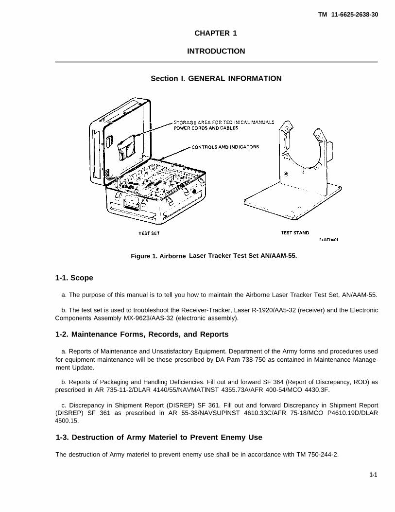
Figure 1. Airborne Laser Tracker Test Set AN/AAM-55.
1-1. Scope
a. The purpose of this manual is to tell you how to maintain the Airborne Laser Tracker Test Set, AN/AAM-55.
b. The test set is used to troubleshoot the Receiver-Tracker, Laser R-1920/AA5-32 (receiver) and the ElectronicComponents Assembly MX-9623/AAS-32 (electronic assembly).
1-2. Maintenance Forms, Records, and Reports
a. Reports of Maintenance and Unsatisfactory Equipment. Department of the Army forms and procedures usedfor equipment maintenance will be those prescribed by DA Pam 738-750 as contained in Maintenance Manage-ment Update.
b. Reports of Packaging and Handling Deficiencies. Fill out and forward SF 364 (Report of Discrepancy, ROD) asprescribed in AR 735-11-2/DLAR 4140/55/NAVMATlNST 4355.73A/AFR 400-54/MCO 4430.3F.
c. Discrepancy in Shipment Report (DISREP) SF 361. Fill out and forward Discrepancy in Shipment Report(DISREP) SF 361 as prescribed in AR 55-38/NAVSUPlNST 4610.33C/AFR 75-18/MCO P4610.19D/DLAR4500.15.
1-3. Destruction of Army Materiel to Prevent Enemy Use
The destruction of Army materiel to prevent enemy use shall be in accordance with TM 750-244-2.
1-1

1-4. Preparation for Storage or Shipment
Prepare the ALT test set for storage or shipment as described in paragraphs 2-4, 2-5, 2-25, 2-26, and 2-27.
1-5. Nomenclature Cross-Reference List
official nomenclature and common names are listed in table 1-1.
Table 1-1. Nomenclature Cross-Reference
Official Nomenclature Common Name
Test Set, Airborne Laser Tracker, AN/AAM-55 ALT Test SetTest Set, Laser, TS-3482/AAM-55 Test SetTest Stand, Receiver MT-4699/AAM-55 Test Stand
1-6. Reporting Equipment Improvement Recommendations (EIR)
If your ALT test set needs improvement, let us know. Send us an EIR. You, the user are the only one who can tell uswhat you don’t like about your equipment. Let us know why you don’t like the design. Put it on an SF 368 (QualityDeficiency Report). Mail it to Commander, US Army Communications - Electronics Command and Fort Monmouth,ATTN: DRSEL-ME-MP, Fort Monmouth, New Jersey 07703. We’ll send you a reply.
Section Il. EQUIPMENT DESCRIPTION AND DATA
1-7. Equipment Characteristics, Features and Capabilities
a. The characteristics and features of the test set are:
(1) The ALT test set is portable and can be used when the environmental and power requirements are available(para 1-9).
(2) All operating controls are on the front panel. Cables and technical manual are stored inside top cover.
(3) Calibration is not required.
b. Capabilities. The test set will fault isolate the ALT receiver and electronic assembly to the major subassemblylevel.
1-2
TM 11-6625-2638-30

TM 11-6625-2638-30
1-8. Location and Description of Major Components (fig. 1-2)
The major components of the test set are as follows:
a. Test Set Cover (1) Provides a place to store power cords, technical manual and test cables(W1, W2, and W3).
b. Test Stand (2) Provides a mounting surface for the ALT receiver during trouble shooting
c. Cable (3)
d. Cable (4)
e. Cable (5)
and repair.
Cable W3 connects the test set to the ALT receiver.
Cable W2 connects the test set to the ALT electronic assembly.
Cable W1 connects the test set to the ALT electronic assembly.
Figure 1-2. ALT Major Components.
1-3

TM 11-6625-2638-30
1-9. Equipment Data
Test Set
WEIGHT (approximate)
30 pounds
DIMENSIONS
Width 22 inchesHeight 13 inchesDepth 22 Inches
ENVIRONMENTAL OPERATING RANGES
Temperature -18° to + 55°CHumidity O to 98%Altitude 10,000 ft maximum
Test Stand
3.5 pounds
12 inches13 inches12 inches
NOTE
No primary power connections are supplied with the test set. Refer to table2-3 for power connections.
PRIMARY POWER REQUIREMENTS
DC Power 28 vdcAC Power 115 vac, 400 Hz
FUSES
DC PowerAC Power
10 amp2 amp
NoneNone
NoneNone
Section Ill. PRINCIPLES OF OPERATION
1-10. General Information
The following paragraphs present an overall block diagram analysis of the test set. The analysis is divided into eightmajor areas which describe the circuitry within the test set involved in troubleshooting the ALT receiver or electronicassembly. To supplement the narrative description, a block diagram is provided for each functional area.
1-4

TM 11-6625-2638-30
1-11. Receiver Cage Test Functional Description (fig. 1-3)
a. Torque motor power (28 vdc) is supplied from the test set power supply through MOTOR PWR switch S19.Resolver outputs from the receiver are monitored from the SERVO jacks through SERVO switch S8.
b. The receiver high or low azimuth servo gain is selected by switching AZIMUTH GAIN switch S5 between-20 vdc for high gain and open for low gain.
c. When GIMBAL COMD switch S17 is in the CAGE position, the appropriate elevation and azimuth servo com-mands are selected from the circuit card assembly and applied to the receiver.
Figure 1-3. Receiver Cage Test Block Diagram.
1-5

TM 11-6625-2636-30
1-12. Receiver Scan Test Functional Description (fig. 1-4)
a. To initiate the scanning mode, a plus or minus 5 vdc is applied to the EXT AZIMUTH (J24) or EXT ELEV (J23)jacks. The plus or minus 5 vdc is applied to the receiver under test through the GIMBAL COMD switch S17 as theelevation and azimuth servo commands. The plus and minus 5 vdc is supplied by power supply and the polarity isselected by the RCVR CURRENT switch S20.
b. When the servo commands are given, the platform responds with an appropriate movement. The time requiredfor each platform excursion is timed by a stopwatch.
Figure 1-4. Receiver Scan Test Block Diagram.
1-6
TM 11-6625-2638-30
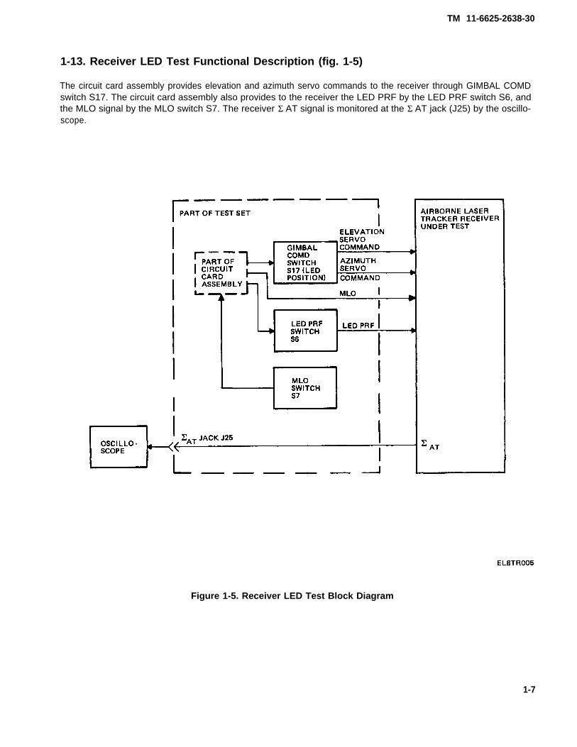
1-13. Receiver LED Test Functional Description (fig. 1-5)
The circuit card assembly provides elevation and azimuth servo commands to the receiver through GIMBAL COMDswitch S17. The circuit card assembly also provides to the receiver the LED PRF by the LED PRF switch S6, andthe MLO signal by the MLO switch S7. The receiver Σ AT signal is monitored at the Σ AT jack (J25) by the oscillo-scope.
Figure 1-5. Receiver LED Test Block Diagram
1-7

1-14. Electronic Assembly Power Supply Test Functional Description (fig. 1-6)
The DVM/SCOPE switch (S3) takes the electronic assembly power supply voltages selected by ELEC VOLTAGEswitch S21 and routes them to the ELECT DVM jacks. The DVM indications are used to determine if the voltagesare within allowed tolerances.
Figure 1-6. Electronic Assembly Power Supply Test Block Diagram.
1-8
TM 11-6625-2638-30

TM 11-6625-2638-30
1-15. Electronic Assembly Cage (Standby) Test Functional Description (fig. 1-7)
a. MODE switch S1 provides the logic commands to the circuit card which then generates simulated servo out-puts to the electronic assembly to simulate the receiver cage positions.
b. The electronic assembly azimuth and elevation commands and discrete signals to be tested are selected byDVM/SCOPE switch S3 and are monitored at the ELECT DVM jacks.
c. CAGE lamp DS3 comes on to indicate that the electronic assembly has correctly decoded the simulatedresolver outputs, and that the receiver is in the cage position.
1-9
Figure 1-7. Electronic Assembly Cage Test Block Diagram.

TM 11-6625-2638-30
1-16. Electronic Assembly Scan Test Functional Description (fig. 1-8)
a. MODE switch S1 provides the scan mode commands and logic to the circuit card to cause servo output simula-tions, and the modulator time constant to be generated.
b. SCAN switch S4 selects the azimuth servo commands and directs them as scanning commands to the circuitcard. The circuit card servo simulations of step a are synchronized by the scanning commands.
c. SCAN lamp DS5 comes on when the electronic assembly scan logic indicator output has been received.
d. DVM/SCOPE switch S3 selects the azimuth and elevation commands and discrete signals to be monitored atthe SCOPE test jacks.
e. FO from the electronic assembly is available for monitoring by a counter, at the FO test jack (J12).
f. CODE switch S2 provides the code select logic levels. TRACK, MLO, and Σ AT presence test jacks (J37, J35,J39) provides access to the electronic assembly track discrete, MLO, and Σ AT signals.
1-10

TM 11-6625-2638-30
Figure 1-8. Electronic Assembly Scan Test Block Diagram.
1-11

1-17. Electronic Assembly Tracking Test Functional Description (fig. 1-9)
a. MODE switch S1 provides the scan mode commands to the electronic assembly.
b. The MLO signal is applied to the circuit card and Σ AT switch S11 connects the FO signal to the circuit cardcausing the coding the tracking signals to be generated.
c. Σ AT CODING/TRACKING switch S12 selects the coding or tracking signal and applies it to another section ofthe circuit card to cause the Σ AT signal to be generated.
d. The LED PRF is applied to the circuit card for proper timing of the Σ AT signal and is also made available formonitoring at the LED PRF jack (J40).
e. The RESET switch S13 resets and starts the circuits that generate the azimuth and elevation outputs as well asthe Σ AT output.
f. TRACKING FILTER switch S15 selects the azimuth and elevation outputs and directs them to the electronicassembly as the port, starboard, up, and down signals simulating the receiver servo output tracking patterns.
g. The pilot track discrete causes TRACK lamp DS7 to come on indicating that the system is in the track mode.
h. The electronic assembly azimuth and elevation signals to be monitored are selected by the DVM/SCOPEswitch S3 and are monitored at the ELECT SCOPE jacks.
1-12
TM 11-6625-2638-30

TM 11-6625-2638-30
Figure 1-9.Electronic Assembly Tracking Test Block Diagram.
1-13

TM 11-6625-2638-30
1-18. Electronic Assembly BITE Test Functional Description (fig. 1-10)
a. MODE switch S1 provides the pilot test logic and the clock disable command. It also provides the test addressactivation to ADDRESS switches S16 and S18.
b. ADDRESS switches A and B select the test address by selecting the appropriate resolver simulator circuits ofthe circuit card assembly. The circuit card provides these selected simulted servo outputs to the electronic assem-bly.
c. The FT jack on the test set provides a monitoring point for the FT logic signal.
d. The MLO signal is applied to circuit card assembly and Σ AT switch S11 connects the FO signal to the circuitcard assembly causing the coding and tracking signals to be generated.
e. Σ AT CODING/TRACKING switch S12 selects the coding or tracking signal and applies it to another section ofthe circuit card assembly to cause the Σ AT signal to be generated.
f. The LED PRF is applied to the circuit card for proper timing of the Σ AT signal and is also made available formonitoring at the LED PRF jack (J40).
g. TRACKING FILTER switch S15 selects the azimuth and elevation outputs and directs them to the electronicassembly as the port, starboard, up, and down signals simulating the receiver servo output tracking patterns.
h. The RESET switch S13 resets and starts circuits that generate the azimuth and elevation outputs as well as theΣ AT output.
1-14

TM 11-6625-2638-30
Figure 1-10. Electronic Assembly BITE Track Block Diagram.
1-15/(1-16 blank)


TM 11-6625-2638-30
CHAPTER 2
MAINTENANCE INSTRUCTIONS
Section I. REPAIR PARTS, SPECIAL TOOLS; TEST, MEASUREMENT, AND DIAGNOSTICEQUIPMENT (TMDE); AND SUPPORT EQUIPMENT
2-1. Common Tools and Equipment
For authorized common tools and equipment refer to the Modified Table of Organization and Equipment (MTOE)applicable to your unit.
2-2. Special Tools, TMDE, and Support Equipment
Refer to the Organizational and Direct Support Maintenance Repair Parts and Special Tools List (RPSTL),TM 11-6625-2638-23P. Also refer to the Maintenance Allocation Chart (MAC) in the Operations and OrganizationalMaintenance Manual, TM 11-6625-2638-12.
2-3. Repair Parts
Repair parts are listed and illustrated in the repair parts and special tools list. TM 11-6625-2638-23P coversorganizational and direct support maintenance for this equipment.
Section Il. SERVICE UPON
2-4. Unpacking
a. Remove the test set and test stand from containers.
b. Save container and packing material for reuse.
2-5. Checking Unpacked ALT Test Set
a. Inspect the equipment for damage incurred during shipment. Ifdamage on SF 364, Report of Discrepancy (ROD).
RECEIPT
the equipment has been damaged, report the
b. Check the equipment against the packing slip to see if the shipment is complete. Report all discrepancies inaccordance with the instructions in DA Pam 738-750.
c. Check to see whether the equipment has been modified. Refer to DA Pam 310-1.
2-1

TM 11-6625-2638-30
Section Ill. TROUBLESHOOTING PROCEDURE
2-7. Test Set Troubleshooting
a. If the fault is known, and can be related to a specific control, indicator, or test jack (fig. 2-1) troubleshoot pertable 2-2.
b. If the fault is not known, troubleshoot per table 2-3.
c. After the test set has been repaired, perform the complete table 2-3 troubleshooting procedure to verify thatthere are no more faults.
Table 2-1. Preliminary Checks
ItemNo.
1
2
3
4
Items to beInspected
Fuses
Knobs
Power Cords
Cables
Procedure
Ensure that good 10 AMP, 2 AMP, and SPAREfuses are installed in proper locations.
Ensure all control knobs are secured properly andare not broken.
Check 115 vac and 28 vdc power cord for damage.
Check cables and connectors for damage. Ensurethat cables W1, W2, and W3 are stored inlid compartment.
2-8. Tools and Equipment
Refer to the Maintenance Allocation Chart (MAC), Tool and Test Equipment Requirements in TM 11-6625-2638-12.
2-9. Controls and Indicators
Refer to FO-1 for locations of the test set controls and indicators.
2-10. Connector Pin Locations
Refer to FO-2 for locations of J1, J2, J3, J4, and J5 connector pins.
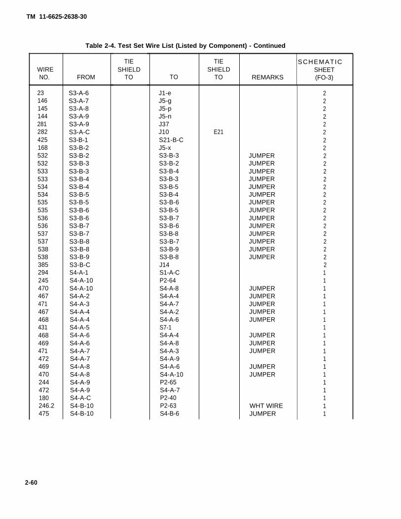
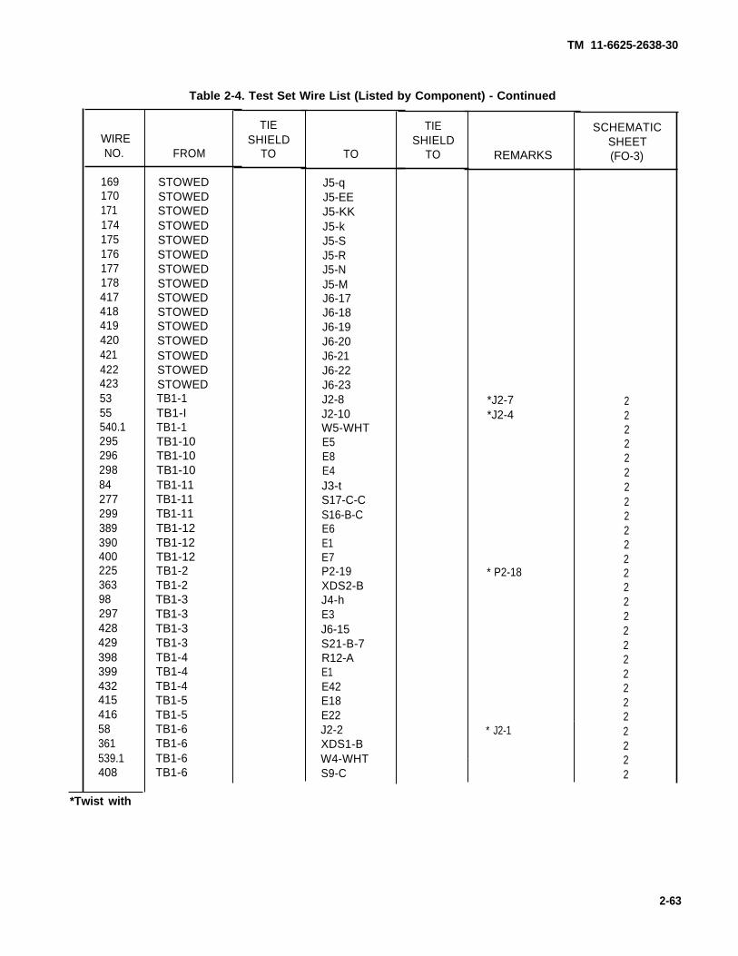
2-11. Schematics and Wire Lists
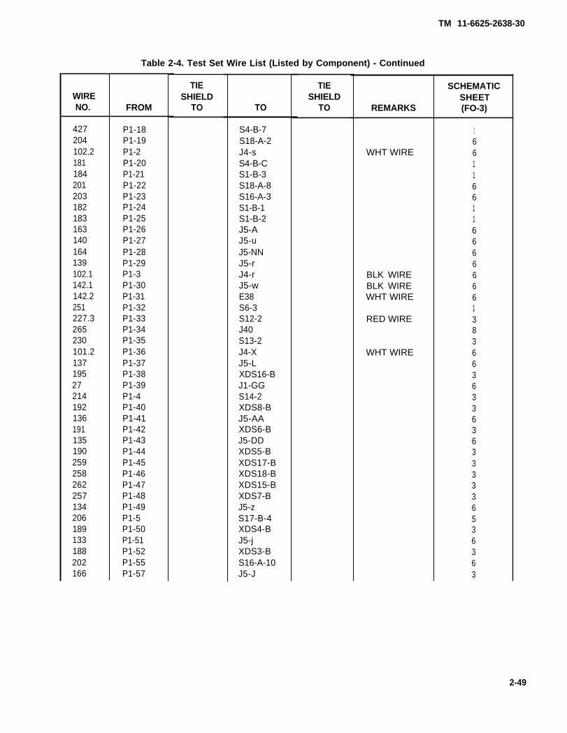
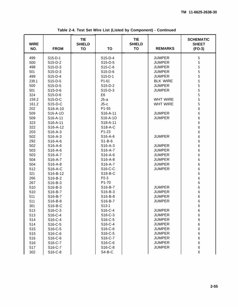
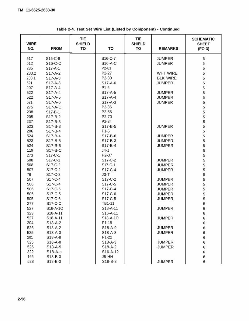
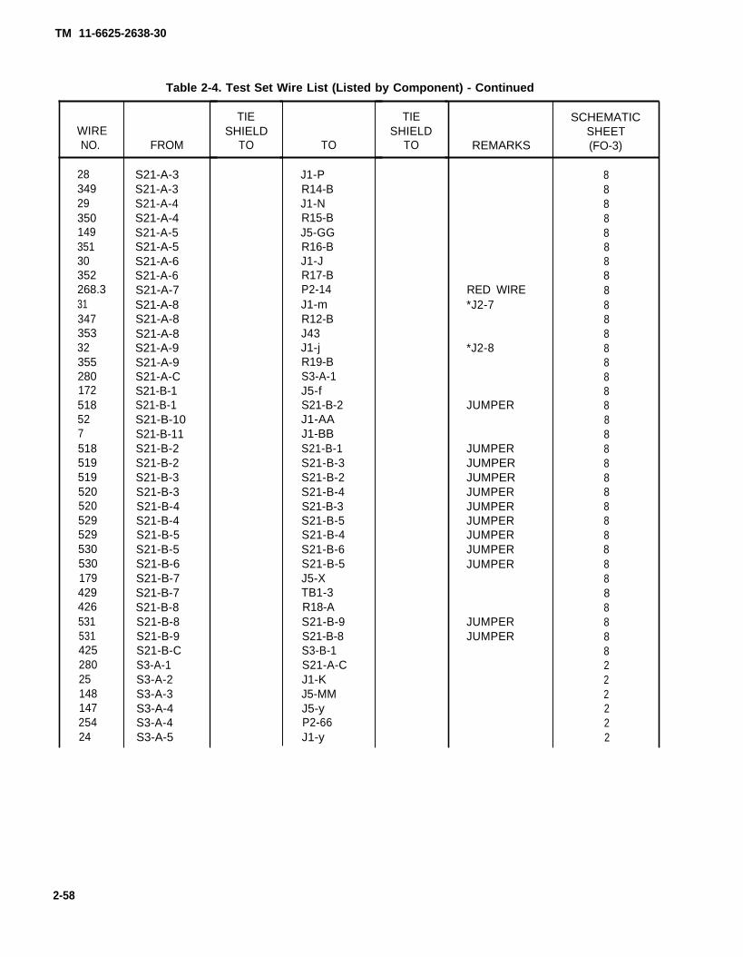
Refer to Test Set Wire List table 2-4 to locate a component’s schematic (FO-3) sheet number.
2-2

TM 11-6625-2638-30
Figure 2-1. Fault Symptom Chart Key.
2-3
TM 11-6625-2638-30
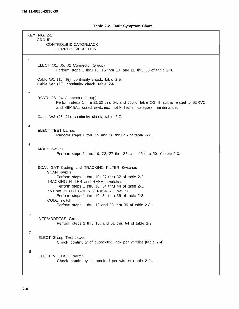
Table 2-2. Fault Symptom Chart
KEY (FIG. 2-1)GROUP
CONTROL/lNDICATOR/JACKCORRECTIVE ACTION
1
2
3
4
5
6
7
8
ELECT (J1, J5, J2 Connector Group)Perform steps 1 thru 10, 15 thru 19, and 22 thru 53 of table 2-3.
Cable W1 (J1, J5), continuity check, table 2-5.Cable W2 (J2), continuity check, table 2-6.
RCVR (J3, J4 Connector Group)Perform steps 1 thru 21,52 thru 54, and 55d of table 2-3. If fault is related to SERVOand GIMBAL cored switches, notify higher category maintenance.
Cable W3 (J3, J4), continuity check, table 2-7.
ELECT TEST LampsPerform steps 1 thru 15 and 36 thru 46 of table 2-3.
MODE SwitchPerform steps 1 thru 10, 22, 27 thru 32, and 45 thru 50 of table 2-3.
SCAN, ΣΑΤ, Coding and TRACKING FILTER SwitchesSCAN switch
Perform steps 1 thru 10, 22 thru 32 of table 2-3.TRACKING FILTER and RESET switches
Perform steps 1 thru 10, 34 thru 44 of table 2-3.ΣΑΤ switch and CODING/TRACKING switch
Perform steps 1 thru 10, 34 thru 39 of table 2-3.CODE switch
Perform steps 1 thru 10 and 33 thru 39 of table 2-3.
BITE/ADDRESS GroupPerform steps 1 thru 15, and 51 thru 54 of table 2-3.
ELECT Group Test JacksCheck continuity
ELECT VOLTAGE switchCheck continuity
of suspected jack per wirelist (table 2-4).
as required per wirelist (table 2-4).
2-4

TM 11-6625-2638-30
Table 2-2. Fault Symptom Chart - Continued
KEY (FIG. 2-1)GROUP
CONTROL/lNDICATOR/JACKCORRECTIVE ACTION
9RCVR
10QDRT
Test JacksCheck continuity of suspected jack per wirelist (table 2-4).
and GIMBAL COMD GroupQDRT lamps
Perform steps 1 thru 13 of table 2-3.GIMBAL COMD switch
Check continuity of switch per wirelist (table 2-3).Notify higher category maintenance.
11SERVO Group
+ and – JacksCheck continuity of
SERVO SwitchCheck continuity of
suspected jack per wirelist (table 2-4).
SERVO switch per wirelist (table 2-4).Notify higher category maintenance.
12RCVR CURRENT Group
Check continuity of suspected jack per wirelist (table 2-4).
13MOTOR PWR, AZIMUTH GAIN, LED PRF and MLO Switches
MOTOR PWRPerform steps 1 thru 10 and 16 thru 19 of table 2-3.
AZIMUTH GAINPerform steps 1 thru 10 and 53 of table 2-3.
LED PRFPerform steps 1 thru 10 and 54 of table 2-3.
MLOPerform steps 1 thru 10 and 54 of table 2-3.
14DVM/SCOPE switch and ELECT SCOPE/DVM Jacks
Check continuity as required per wirelist (table 2-4).
15POWER
Perform steps 1 thru 10 of table 2-3.
16RCVR CURRENT Group
Check continuity of suspected jack per wirelist (table 2-4)
2-5

TM 11-6625-2638-30
Table 2-3. Test Set Troubleshooting
STEPPROCEDURE
NORMAL INDICATIONABNORMAL INDICATION
CORRECTIVE ACTION
1
2
3
4
5
6
2-6
Refer to FO-2 for
Place test set on test bench with lid open.
NOTE
connector pin locations.
Set all switches CCW, 1, down, off or minimum position.
Ensure 115 vac and 28 vdc power source is off before connecting powercables. Contact with 115 vac may cause injury or death.
Connect 28 vdc power as follows:a. Connect green wire to ground.b. Connect white wire to return.c. Connect black wire to 28 vdc.
Connect 115 vac power as follows:a. Connect green wire to ground.b. Connect white wire to return.c. Connect black wire to 115 vat.
Apply power to test equipment,
NOTE
The test set power supply has a 10 second delay.
Place POWER switch to ONAC and DC POWER lamps on
AC lamp offa. Verify that 115 vac power cord is connected to good 115 vac power.b. Check 2 AMP fuse and replace if blown.c. Check AC lamp and replace if open.d. Check continuity (para 2-12).
DC lamp offa.b.c.d.
Verify that 28 vdc power cord is connected to good 28 vdc powerCheck 10 AMP fuse and replace if blown.Check ac Iamp and replace if open.Check continuity (para 2-12).

TM 11-6625-2638-30
Table 2-3. Test Set Troubleshooting - Continued
STEPPROCEDURE
NORMAL INDICATIONABNORMAL INDICATION
CORRECTIVE ACTION
7
8
9
10
11
Press LAMP TEST switch.All lamps shall be on.
One or more lamps off (but not all off).Replace defective lamps.
One or more lamps still off.Check continuity (para 2-12).Replace circuit card (para 2-16).
All lamps off except AC and DC POWER.Check 5 vdc per step 6 a.Check LAMP TEST switch S14 (para 2-12).
Release LAMP TEST switchAll lamps off except AC and DC POWER. TFT lamp may be on or off.All lamps on.
Check for shorted LAMP TEST switch S14 (para 2-12).
Connect return (–) lead of DVM (DC mode) to J4-h.
Measure the power supply voltages at the following connector pins:
J3-D 4.9 to 5.5 vdcRCVR Current + jack 4.9 to 5.5 vdcJ3-C -4.9 to -6.1 vdcJ4-d 13.3 to 14.7 vdcJ3-L -14.0 to –16.0 vdcJ3-K 19.0 to 25 vdcJ4-E –1 9.0 to -25 vdcJ1-h 26.0 to 30.0 vdcJ5-b 13.0 to 15.0 vdcMove DVM Return (–) to J4-q (DVM to AC mode)J4-n 26.0 to 34.0 vacJ4-p 26.0 to 34.0 vac
One or more voltage is higher than maximum.Replace power supply (para 2-19).
All voltages missing.Check relay K1 and interlock S9.
One or more voltages missing but not all.Check wiring and associated resistor (para 2-12).Replace power supply (para 2-19).
Verify that the RCVR CURRENT switch is in the + 5V position.
Do not let the 5 vdc probe short to anything to prevent damage to power sup-ply or test set.
12Connect one end of a test lead with probe to RCVR CURRENT + jack (5 vdc).
2-7

TM 11-6625-2638-30
Table 2-3. Test Set Troubleshooting - Continued
STEPPROCEDURE
NORMAL INDICATIONABNORMAL INDICATION
CORRECTIVE ACTION
13
14
15
16
17
18
Apply + 5 vdc with probe to each of the connector pins while observing the associated lamp.
J5-j CAGEJ5-z LEDJ5-DD SCANJ5-AA CUEJ5-L ADDRESSJ4-Y UPJ4-X DOWNJ4-s LEFTJ4-r RIGHT
Each individual lamp came on when 5 volts were applied, then went off when 5 volts wereremoved.
One or more lamps did not come on or more than one lamp came on at the same time.Replace circuit card (para 2-16).
a. Disconnect test lead from RCVR CURRENT jack.b. Connect the test lead with probe to RCVR GRD jack.
Use probe to ground each of the following connector pins while observing while observing associatedlamp.
J1-v TRACKJ5-h BITEJ1-h RCVRJ1-LL ELECJ1-z GO
Each individual lamp came on when the pin was grounded, then went off when ground wasremoved.
One or more lamps did not come on or more than one lamp came on at a time.Replace circuit card (para 2-16).
Connect DVM to J4-N (-) and J4-L (+).
Set MOTOR POWER switch to LOW.22.5 to 28.5 vdc.
0 vdc.Continuity check wires and
Set MOTOR POWER switch to NORMAL.22.5 to 28.5 vdc.
Continuity check wires and
S19 (para 2-12).
S19 (para 2-12).
2-8
TM 11-6625-2638-30
Table 2-3. Test Set Troubleshooting - Continued
STEPPROCEDURE
NORMAL INDICATIONABNORMAL INDICATION
CORRECTIVE ACTION
19Set MOTOR POWER switch to OFF.
0 vdc.Continuity check wires and S19 (para 2-12).
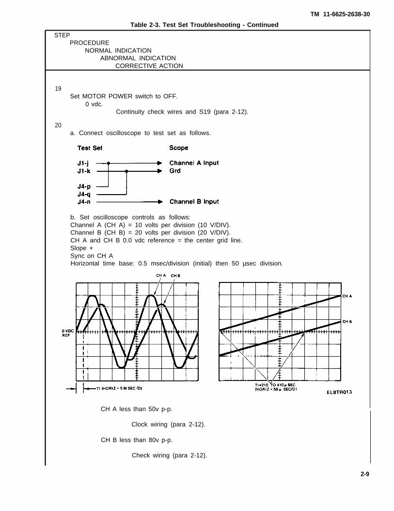
20a. Connect oscilloscope to test set as follows.
b. Set oscilloscope controls as follows:Channel A (CH A) = 10 volts per division (10 V/DIV).Channel B (CH B) = 20 volts per division (20 V/DIV).CH A and CH B 0.0 vdc reference = the center grid line.Slope +Sync on CH AHorizontal time base: 0.5 msec/division (initial) then 50 µsec division.
CH A less than 50v p-p.
Clock wiring (para 2-12).
CH B less than 80v p-p.
Check wiring (para 2-12).
2-9

TM 11-6625-2638-30
Table 2-3. Test Set Troubleshooting - Continued
Check wiring and C1, R18 and R19 (para 2-12).
Replace circuit card (para 2-16).
2-10

TM 11-6625-2638-30
Table 2-3. Test Set Troubleshooting - Continued
STEPPROCEDURE
NORMAL INDICATIONABNORMAL INDICATION
CORECTIVE ACTION
23Connect SCOPE to J5-t (-) and J5-HH (+).
NOTE
● A separate power supply is needed for the following test.● Be sure power supply outputs are not grounded.
24Set power supply to 10 vdc ± 0.1 v and connect to test set per step 25.
25Check peak to peak levels of square waves per following table.
10 VDC PEAK TO PEAKPOWER SUPPLY SCOPE SQUARE WAVE
SUB SCAN SW.STEP POSITION - + RETURN CH-A MINIMUM MAXIMUM
1 SCAN A GND J5-y J5-t J5-HH 0.0 0.52 SCAN A 2 GND J5-y J5-t J5-HH 16.0 24.03 SCAN B GND J5-y J5-t J5-HH 8.0 12.54 SCAN B 2 GND J5-y J5-t J5-HH 18.0 22.05 SCAN B 4 GND J5-y J5-t J5-HH 18.0 22.06 SCAN A 1 J5-y GND J5-t J5-HH 16.0 24.07 SCAN A 3 J5-y GND J5-t J5-HH 16.0 24.08 SCAN B 1 J5-y GND J5-t J5-HH 18.0 22.09 SCAN B 3 J5-y GND J5-t J5-HH 18.0 22.010 SCAN B 5 J5-y GND J5-t J5-HH 18.0 22.0
Per tableHigh or low
Replace circuit board (para 2-16).
26Disconnect power supply from test set.
27Place POWER switch to OFF.
AC and DC POWER lamps off.
28Set MODE switch to SCAN A.
2-11

TM 11-6625-2638-30
Table 2-3. Test Set Troubleshooting - ContinuedSTEP
PROCEDURENORMAL INDICATION
ABNORMAL INDICATIONCORRECTIVE ACTION
29Use DVM to measure resistance between J1-EE and J5-B.
Less than one ohm.One ohm or more.
Check wiring (para 2-12).
30Set MODE switch to SCAN B.
31Use DVM to measure resistance between J1-HH and J5-B.
Less than one ohm.One ohm or more.
Check wiring (para 2-12).
32Place POWER switch to ON.
AC and DC POWER lamps on.
33Use DVM to verify logic levels between J5-B (–) and the following connector pins withcorresponding CODE switch settings.
NOTE
1 = 3.0 vdc min.0 = 0.5 vdc max.- = any
CODE J1-X J1-Y J1-pSWITCH
1 - - 1 1 12 - - o 1 13 - - 1 0 14 - - 0 0 15 - - 1 1 06 - - 0 1 07 - - 1 0 08 - - 0 0 0
2-12

TM 11-6625-2638-30
Table 2-3. Test Set Troubleshooting - Continued
STEPPROCEDURE
NORMAL INDICATIONABNORMAL INDICATION
CORRECTIVE ACTION
33 (cont)
34
35
36
CODE J1-BSWITCH
- 1 - 1- 2 - 0- 3 - 1
0- 5 - 1
0- 7 - 1- 8 - 0
CODE J1-DSWITCH
- - 1 1- -2 0- -3 1- - 4 0- -5 1- - 6 0- -7 1- - 8 0
Per above table.Other than table.
Check wiringNotify higher
- 4 -
- 6 -
J1-Z
11001100
J1-b
11001100
J1-W
11110000
J1-A
11110000
to CODE switch S2 per schematic (FO-3).category maintenance.
a. Place Σ AT ON/OFF switch to ON.b. Place Σ AT CODING/TRACKING switch to CODING.c. Set CODE switch to 688.
Set up signal generator for the following square wave output.
Frequency: 800.00 ± 0.01 KHZ5.0 ± 0.5 vdc0.0 ± 0.5 vdc
Connect signal generator to test set as follows:
SIGNAL GEN Test Set
High to J5-KLow to J5-B
2-13
TM 11-6625-2638-30
Table 2-3. Test Set Troubleshooting – ContinuedSTEP
PROCEDURENORMAL INDICATION
ABNORMAL INDICATIONCORRECTIVE ACTION
37
38
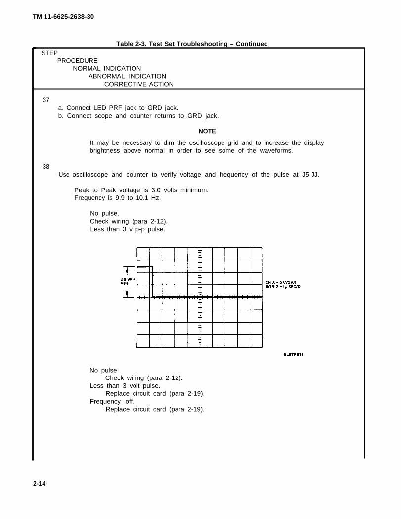
a. Connect LED PRF jack to GRD jack.b. Connect scope and counter returns to GRD jack.
NOTE
It may be necessary to dim the oscilloscope grid and to increase the displaybrightness above normal in order to see some of the waveforms.
Use oscilloscope and counter to verify voltage and frequency of the pulse at J5-JJ.
Peak to Peak voltage is 3.0 volts minimum.Frequency is 9.9 to 10.1 Hz.
No pulse.Check wiring (para 2-12).Less than 3 v p-p pulse.
No pulseCheck wiring (para 2-12).
Less than 3 volt pulse.Replace circuit card (para 2-19).
Frequency off.Replace circuit card (para 2-19).
2-14

TM 11-6625-2638-30
Table 2-3. Test Set Troubleshooting - ContinuedSTEP
PROCEDURENORMAL INDICATION
ABNORMAL INDICATIONCORRECTIVE ACTION
39Use oscilloscope and counter to verify the pulse at J5-w.
Peak to peak voltage is 3.0 volts minimum.Frequency is 9.9 to 10.1 Hz.
No pulse.Check wiring (para 2-12).
Less than 3 volt pulse.Replace circuit card (para 2-16).
Frequency off.Replace circuit card (para 2-16).
40Connect J5-JJ to J5-C.
41Connect scope to TRACK TRIGGER test jack.
2-15

TM 11-6625-2638-30
Table 2-3. Test Set Troubleshooting - Continued
STEPPROCEDURE
NORMAL INDICATIONABNORMAL INDICATION
CORRECTIVE ACTION
42
43
44
Verify that the following pulse occurs when the TRACKING FILTER RESET switch is depressed.
Pulse missing.Check wiring (para 2-12).
Wrong voltage levels.Replace circuit card (para 2-16).
Wrong pulse width. Replace circuit card (para 2-16).
a. Remove jumper wires (do not disconnect signal generator).b. Connect DVM negative lead to GRD jack.
Use DVM to verify logic levels for TRACKING FILTER switch positions as follows:a. Set TRACKING FILTER switch to ELEV A.
b. Depress and release TRACKING FILTER RESET switch.
TFT lamp goes off, then comes back on.J5-d is 3.5 to 5.5 vdc.J5-Z is 3.5 to 5.5 vdc.J5-c is 0.0 ± 0.5 vdc.J5-a is 0.0 to 0.5 vdc.
Other than above.Check wiring (para 2-12).Replace circuit card (para 2-16).
2-16

TM 11-6625-2638-30
Table 2-3. Test Set Troubleshooting - ContinuedSTEP
PROCEDURENORMAL INDICATION
ABNORMAL INDICATIONCORRECTIVE ACTION
44 (cont)
c. Set TRACKING FILTER switch to ELEV B.
d. Depress and release TRACKING FILTER RESET switch.TFT lamp goes off, then comes back on.J5-d is 3.0 to 5.5 vdc.J5-Z is 3.0 to 5.5 vdc.J5-c is 0.0 to 0.5 vdc.J5-a is 0.0 to 0.5 vdc.
Other than above.Replace circuit card (para 2-16).
e. Set TRACKING FILTER switch to ELEV C.
f. Depress and release TRACKING FILTER RESET switch.TFT lamp goes off then comes back on.J5-d is 0.0 to 0.5 vdc.J5-Z is 0.0 to 0.5 vdc.J5-c is 0.0 to 0.5 vdc.J5-a is 0.0 to 0.5 vdc.
Other than above.Replace circuit card (para 2-16).
g. Set TRACKING FILTER switch to AZIMUTH A.
h. Depress and release TRACKING FILTER RESET switch.TFT lamp goes off then comes back on.J5-d is 3.0 to 5.5 vdc.J5-Z is 3.0 to 5.5 vdc.J5-c is 0.0 to 0.5 vdc.J5-a is 0.0 to 0.5 vdc.
Other than above.Replace circuit card (para 2-16).
i. Set TRACKING FILTER switch to AZIMUTH B.
j. Depress and release TRACKING FILTER RESET switch.TFT lamp goes off, then comes back on.J5-d is 3.0 to 5.5 vdc.J5-Z is 3.0 to 5.5 vdc.J5-c is 0.0 to 0.5 vdc.J5-a is 0.0 to 0.5 vdc.
Other than above.Replace circuit card (para 2-16).
2 - 1 7
TM 11-6625-2638-30
Table 2-3. Test Set Troubleshooting – continued
STEPPROCEDURE
NORMAL INDICATIONABNORMAL INDICATION
CORRECTIVE ACTION
44 (cont)
45
46
47
48
49
2-1 8
k. Set TRACKING FILTER switch to AZIMUTH C.
1. Depress TRACKING FILTER RESET switch.TFT lamp goes off, then comes back on.J5-d is 0.0 to 0.5 vdc.J5-Z is 0.0 to 0.5 vdc.J5-c is 0.0 to 0.5 vdc.J5-a is 0.0 to 0.5 vdc.
Other than above.Replace circuit card (para 2-16).
Set MODE switch to CUE.
Disconnect signal generator.
Set SCAN switch to SCAN A.a. Use DVM (AC mode) to measure voltage between;b. J1-t and J1-s
5.0 ± 0.5 vac
c. J1-u and J1-c
5.0 ± 0.5 vacOther than above.
Check wiring (para 2-12).Replace circuit card (para 2-16).
Set the MODE switch to BITE.
Connect SCOPE input to J5-LL.
TM 11-6625-2638-30
Other than above.Check wiring (para 2-12).Replace circuit card (para 2-16).
Table 2-3. Test Set Troubleshooting – Continued
STEPPROCEDURE
NORMAL INDICATIONABNORMAL INDICATION
CORRECTIVE ACTION,
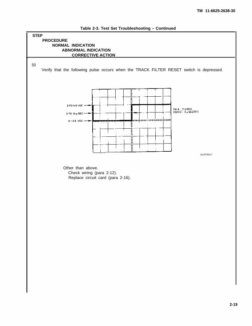
50Verify that the following pulse occurs when the TRACK FILTER RESET switch is depressed.
EL8TR017
2-19

TM 11-6625-2638-30
Table 2-3. Test Set Troubleshooting - Continued
STEPPROCEDURE
NORMAL INDICATIONABNORMAL INDICATION
CORRECTIVE ACTION
51Use DVM in AC mode (return to GRD) to verify voltages with ADDRESS A and B switchesset as follows:
ADDRESS
A—
123456789
1011
12-2312-2312-2312-2312-2312-2312-2312-2312-2312-2312-2312-23
B—
1212121212121212121212121314151617181920212223
J5
PIN
rrrrrrrrrrrrrrrrrrrrrrr
isisisisisisisisisisisisisisisisisisisisisisis
0.0 ± 0.25 vac0.0 ± 0.25 vac4.33 to 4.73 vac0.0 ± 0.25 vac0.0) ± 0.25 vac4.33 to 4.73 vac4.33 to 4.73 vac4.33 to 4.73 vac0.0 ± 0.25 vac4.75 to 5.25 vac4.75 to 5.25 vac0.0 ± 0.25 vac0.0 ± 0.25 vac4.75 to 5.15 vac0.0 ± 0.25 vac0.0 ± 0.25 vac0.0 ± 0.25 vac0.0 ± 0.25 vac4.75 to 5.15 vac0.0 ± 0.25 vac4.75 to 5.25 vac4.75 to 5.25 vac0.0 ± 0.25 vac
2-20

TM 11-6625-2638-30
Table 2-3. Test Set Troubleshooting - Continued
STEPPROCEDURE
NORMAL INDICATIONABNORMAL INDICATION
CORRECTIVE ACTION
51 (cont)A
123456789
1011
12-2312-2312-2312-2312-2312-2312-2312-2312-2312-2312-2312-23
123456789
1011
12-2312-2312-2312-2312-2312-2312-2312-2312-2312-2312-2312-23
B
1212121212121212121212121314151617181920212223
1212121212121212121212121314151617181920212223
PIN
uuuuuuuuuuuuuuuuuuuuuuu
AAAAAAAAAAAAAAAAAAAAAAA
isisisisisisisisisisisisisisisisisisisisisisis
isisisisisisisisisisisisisisisisisisisisisisis
0.0 ± 0.25 vac0.0 ± 0.25 vac2.01 to 2.21 vac2.01 to 2.21 vac2.01 to 2.21 vac2.01 to 2.21 vac2.01 to 2.21 vac2.01 to 2.21 vac0.0 ± 0.25 vac0.0 ± 0.25 vac0.0 ± 0.25 vac0.0 ± 0.25 vac
0.65 to 0.73 vac0.0 ± 0.25 vac0.0 ± 0.25 vac0.0 ± 0.25 vac0.0 ± 0.25 vac0.0 ± 0.25 vac0.0 ± 0.25 vac0.65 to 0.73 vac0.0 ± 0.25 vac0.0 ± 0.25 vac0.0 ± 0.25 vac
0.0 ± 0.25 vac0.0 ± 0.25 vac2.16 to 2.36 vac0.0 ± 0.25 vac0.0 ± 0.25 vac2.16 to 2.36 vac2.16 to 2.36 vac2.16 to 2.36 vac0.0 ± 0.25 vac4.75 to 5.25 vac4.75 to 5.25 vac0.0 ± 0.25 vac0.0 ± 0.25 vac0.0 ± 0.25 vac0.0 ± 0.25 vac0.0 ± 0.25 vac0.0 ± 0.25 vac0.0 ± 0.25 vac0.0 ± 0.25 vac0.0 ± 0.25 vac4.75 to 5.25 vac4.75 to 5.25 vac0.0 ± 0.25 vac 2 - 2 1

Table 2-3. Test Set Troubleshooting - Continued
STEPPROCEDURE
NORMAL INDICATIONABNORMAL INDICATION
CORRECTIVE ACTION
51 (cont)A
123456789
1011
12-2312-2312-2312-2312-2312-2312-2312-2312-2312-2312-2312-23
12-2312-23
B
1212121212121212121212121314151617181920212223
1419
PIN
NNNNNNNNNNNNNNNNNNNNNNNNNNNNNNNNNNNNNNNNNNNNNN
HHHH
isisisisisisisisisisisisisisisisisisisisisisis
isis
0.0 ± 0.25vac0.0 ± 0.25vac0.0 ± 0.25vac0.0 ± 0.25vac0.0 ± 0.25vac0.0 ± 0.25vac0.0 ± 0.25vac0.0 ± 0.25vac0.0 ± 0.25vac0.0 ± 0.25vac0.0 ± 0.25vac0.0 ± 0.25vac0.0 ± 0.25vac4.75 to 5.15 vac0.0 ± 0.25 vac0.0 ± 0.25 vac0.0 ± 0.25 vac0.0 ± 0.25 vac4.75 to 5.15 vac0.0 ± 0.25 vac0.0 ± 0.25 vac0.0 ± 0.25 vac0.0 ± 0.25 vac
0.00 to 0.35 vac0.0 to 0.35 vac
Per tableMost voltages good, but some missing.
Continuity from applicable connector pin (para 2-12).Repair wiring.
All voltages missing.Replace circuit card (para 2-16).
2-22
TM 11-6625-2638-30
TM 11-6625-2638-30
Table 2-3. Test Set Troubleshooting - Continued
STEPPROCEDURE
NORMAL INDICATIONABNORMAL INDICATION
CORRECTIVE ACTION
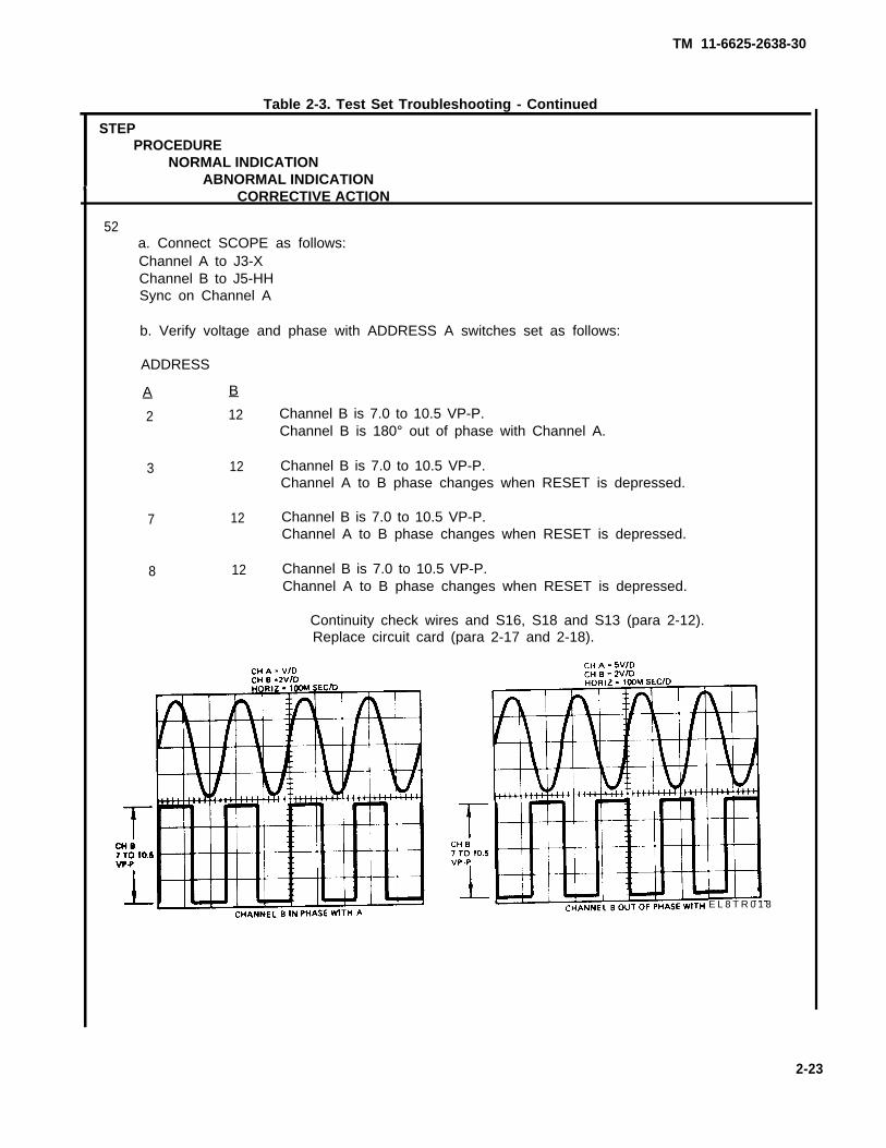
52a. Connect SCOPE as follows:Channel A to J3-XChannel B to J5-HHSync on Channel A
b. Verify voltage and phase with ADDRESS A switches set as follows:
ADDRESS
A B
2 12 Channel B is 7.0 to 10.5 VP-P.Channel B is 180° out of phase with Channel A.
3 12 Channel B is 7.0 to 10.5 VP-P.Channel A to B phase changes when RESET is depressed.
7 12 Channel B is 7.0 to 10.5 VP-P.Channel A to B phase changes when RESET is depressed.
8 12 Channel B is 7.0 to 10.5 VP-P.Channel A to B phase changes when RESET is depressed.
Continuity check wires and S16, S18 and S13 (para 2-12).Replace circuit card (para 2-17 and 2-18).
E L 8 T R 0 1 8
2-23

TM 11-6625-2638-30
Table 2-3. Test Set Troubleshooting - ContinuedSTEP
PROCEDURENORMAL INDICATION
ABNORMAL INDICATIONCORRECTIVE ACTION
53
54
a. Connect DVM (DC Mode) between J4-K (+) and J5-B (-).b. Place AZIMUTH GAIN switch to HIGH.
–19 to –25 vdc.O vdc.
Check wiring (para 2-12).
c. Place AZIMUTH GAIN switch to LOW0 vdc (open circuit).
Check wiring (para 2-12).–19 to -25 vdc.
Replace AZIMUTH GAIN switch (para 2-21).
a. Place the LED PRF and MLO switches to ON.
Connect SCOPE as follows:Channel A to J4-iChannel B to J4-jSync on Channel ASlope +
b. Verify the Pulse widths and levels of the following wave forms.
EL8TR019
2-24

TM 11-6625-2638-30
Missing pulse.Check wiring (para 2-12).Replace circuit card (para 2-17 and
Voltage levels or wrong pulse width.Replace circuit card (para 2-17 and
c. Verify the following periods.
2-1 8).
2-18).
Table 2-3. Test Set Troubleshooting - Continued
STEPPROCEDURE
NORMAL INDICATIONABNORMAL INDICATION
CORRECTIVE ACTION
54 (cont)
Period is less than 25 or more than 45 Msec.Replace circuit card (para 2-17 and 2-18).
d. Move the scope Channel B load to J4-G.
EL8TR020
EL8TR021
2-25

TM 11-6625-2636-30
0 vdc on J4-G.Check wiring (para 2-12).
Pulses on J4-G.Replace circuit card (para 2-17 and 2-18).
e. Move the scope Channel B load to J4-F.
Table 2-3. Test Set Troubleshooting - Continued
STEPPROCEDURE
NORMAL INDICATIONABNORMAL INDICATION
CORRECTIVE ACTION
54 (cont)
EL6TR022
Pulses on J4-J or more than 0.5 vdc.Replace circuit card (para 2-17 and 2-18).
2-26
TM 11-6625-2638-30
Table 2-3. Test Set Troubleshooting - Continued
STEPPROCEDURE
NORMAL INDICATIONABNORMAL INDICATION
CORRECTIVE ACTION
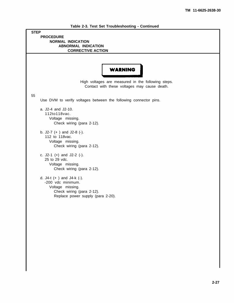
High voltages are measured in the following steps.Contact with these voltages may cause death.
55Use DVM to verify voltages between the following connector pins.
a. J2-4 and J2-10.112to118vac.
Voltage missing.Check wiring (para 2-12).
b. J2-7 (+ ) and J2-8 (-).112 to 118vac.
Voltage missing.Check wiring (para 2-12).
c. J2-1 (+) and J2-2 (-).25 to 29 vdc.
Voltage missing.Check wiring (para 2-12).
d. J4-t (+ ) and J4-k (-).-200 vdc minimum.
Voltage missing.Check wiring (para 2-12).Replace power supply (para 2-20).
2-27

TM 11-6625-2638-30
Table 2-3. Test Set Troubleshooting - Continued
STEPPROCEDURE
NORMAL INDICATIONABNORMAL INDICATION
CORRECTIVE ACTION
56Use DVM to measure voltages between each of the following pairs of pins.
J3-Z and J3-q.8.94 to 9.04 vat.
Out of tolerance.Adjust R196 per para 2-13.
J3-j and J3-m.3.03 to 3.13 vat.
Out of tolerance.Adjust R197 per para 2-14.
J3-p and J3-b.3.03 to 3.13 vat.
Out of tolerance.Same voltage as J3-m, check continuity and correct wiring as required.
57Place POWER switch to OFF.
AC and DC lamps off.
2-28
TM 11-6625-2638-30
Section IV. MAINTENANCE PROCEDURES
2-12. Checking Continuity – General Instructions
Ensure that the test set power cords (115 vac and 28 vdc) are disconnectedfrom power source. Contact with 115 vac or the internal 300 vdc may causeinjury or death.
a. Place test set POWER switch to OFF.
b. Remove test set from the case (para 2-15).
NOTE
Refer to schematic diagram (FO-3) and wire lists (tables 2-4 and 2-5) whencontinuity checking.
c. Check the continuity of each wire, switch, or component as applicable to the circuit.
d. Replace components as required (para 2-17 through para 2-24).
2-13. R196 Adjustment Procedure (fig. 2-3)
Perform adjustment of R196 as follows:
a. Remove test set from case (para 2-15).
High voltage is present. When power is applied to test set, voltages as highas 115 vac and 300 vdc are present. Contact with high voltages may causeinjury or death.
b. Manually activate interlock switch S9.
c. Reconnect ac and dc POWER cords.
d. Connect DVM (AC mode) between J3-z and J3-q.
e. Place POWER switch to ON.
f.
9.
h.
Adjust RI 96 on circuit board to 8.99 vac ± 0.05 vat.
Place POWER switch to OFF.
Disconnect ac and dc POWER cords.
2-29

TM 11-6625-2638-30
i. Install test set into case (para 2-16).
j. Place POWER switch to ON,
k. Repeat table 2-3, step 56.
2-14. R197 Adjustment Procedure (fig. 2-3)
Perform adjustment of RI 97 as follows:
a.
b.
c.
d.
e.
f.
Remove test set from case (para 2-15).
High voltage is present. When power is applied to test set, voltages as highas 115 vac and 300 vdc are present. Contact with high voltages may causeinjury or death.
Manually activate interlock switch S9.
Reconnect ac and dc POWER cords.
Connect DVM (AC mode) between J3-z and J3-q.
Place POWER switch to ON.
Adjust R197 on circuit board to 3.08 vac ± 0,05 vat.
g. Place POWER switch to OFF.
h. Disconnect ac and dc POWER cords.
i. Install test set into case (para 2-16).
j. Place POWER switch to ON.
k. Repeat table 2-3, step 56.
2-15. Removing Test Set from Case (fig. 2-2)
a. Remove ac and dc power cords from inner case cover storage compartment.
b. Remove the twelve screws and washer from the front panel edge.
NOTE
It maybe necessary to carefully pry the edge of the panel to break the seal ifthe gasket is stuck.
c. Lift test set from case using handles provided.
2-30

2-16. Installing Test Set into Case (fig. 2-2)
a.
b.
c.
d,
Place gasket in position on case.
Carefully lift test set and install into case. Check that interlock switch is actuated by bracket inside case.
Install the twelve screws with washers that secure the panel to the case.
Torque screws to approximately 18 inch-pounds.
2-17. Removing Circuit Card (fig. 2-3)
a. Remove test set from case (para 2-15).
b. Loosen screws (5, 10, 11) securing connectors P1, P2 and P3 to circuit card and remove connectors.
c. Remove the twelve screws (9) with washers (6, 7, 8) that hold the circuit board to the twelve standoffs (4). Donot lose the plastic washers that are located between the circuit board and standoffs.
d. Carefully lift circuit card from test set.
e. Install new circuit card (para 2-18).
2-18. Installing Circuit Card (fig. 2-3)
a
b
c
Install twelve plastic washers (6) on spacers.
Carefully lay circuit card assembly on plastic washers.
Align holes in circuit card with holes in washers and spacers.
d. Install twelve plastic washers (6), twelve steel washers (7), twelve Iockwashers (8), and twelve screws.
e. Install connectors P1, P2 and P3 on circuit card and tighten retaining screws (5, 10, 11).
f. Replace test set into case (para 2-16).
2-31
TM 11-6625-2638-30

TM 11-6625-2638-30
EL8TR024
Figure 2-2. Test Set to Case Details.
2-32

TM 11-6625-2636-30
Figure 2-3. Test Set Components.
EL8TR025
2-33

TM 11-6625-2638-30
2-19. Removing Power Supply (fig. 2-3)
a. Remove test set from case (para 2-15).
b. Remove the four screws (1) with washers (2) that secure power supply (3) to assembly.
c. Remove power supply (3) by pulling straight out.
d. Install replacement power supply (para 2-20).
2-20. Installing Power Supply (fig. 2-3)
Be sure that power supply connector pins align with socket in chassis, toprevent bending or breaking of pins.
a. Align power supply with connector and install power supply.
b. install four screws (1) with washers (2).
c. install test set into case (para 2-16).
2-34

TM 11-6625-2638-30
2-21. Switch Replacement (fig. 2-4)
a. If necessary to gain access to switch, remove circuit board (para 2-17).
b. Tag wires for reinstallation and unsolder wires.
c. Remove attaching hardware (1).
d. Install replacement switch (2) using attaching hardware (1).
e. Reconnect and solder wires.
f. To be sure, check continuity reinstalled wires (table 2-4 or 2-5).
g. If removed, install circuit card (para 2-18).
h. Install test set into case (para 2-16).
EL8TR026
Figure 2-4. Switches.
2-35

TM 11-6625-2638-30
2-22. Lamp Holder Replacement (fig. 2-5)
a. If necessary to gain access to lamp holder, remove circuit card (para 2-17),
b. Tag wires for reinstallation and unsolder wires.
c. Remove attaching hardware (1).
d. Replace lamp holder (2) using attaching hardware (1).
e. Reconnect and solder wires.
f. To be sure, check continuity reinstalled wires (table 2-4 or 2-5).
g. If removed, install circuit card (para 2-18).
h. Install test set into case (para 2-16).
E L8TR027
Figure 2-5. Lamp Holders.
2-36

TM 11-6625-2638-30
2-23. Fuse Holder Replacement (fig. 2-6)
a. If necessary to gain access to fuse holder, remove circuit card (para 2-17).
b. Tag wires for reinstallation and unsolder wires.
c. Remove attaching hardware (1).
d. Install replacement fuse holder (2) using attaching hardware (1).
e. Reconnect and solder wires.
f. To be sure, check continuity reinstalled wires (table 2-4 or 2-5).
g. If removed, install circuit card (para 2-18).
h. Install test set into case (para 2-16).
EL8TR028
Figure 2-6. Fuse Holder.
2-37

2-24. Test Jack Replacement (fig. 2-6)
a. If necessary to gain access to test jack, remove circuit card (para 2-17).
b. Tag wires for reinstallation and unsolder wires.
c. Remove attaching hardware (1).
d. Install replacement test jack (2) using attaching hardware (1).
e. Reconnect and solder wires.
f. To be sure, check continuity reinstalled wires (table 2-4 or 2-5).
g. Install test set into case (para 2-16).
EL8TRO29
Figure 2-7. Test Jacks.
2-38
TM 11-6625-2638-30

TM 11-6625-2638-30
WIRENO.
371372373208291382541424364390399406446447443414413444448412410448415453443444445446447410381406539.3540.3454411411412
FROM
Cl-ACl-ACl-BC2-AC2-AC2-BCR3-CCR2-ACR2-CE1E1E1E1OE11E12El 3E14E15E16E17E18E18E18E18E19E19E19E19E19E19E2E2E2E2E20E21E22E22
Table 2-4. Test Set Wire List (Listed by Component)
TIESHIELD
TO TO
J6-6R9-AR1O-AP2-23S1-c-cE6R5-AK1-B1J6-3TB1-12TB1-4E2E19E19E19E22E22E19E18E22E19E16TB1-5E39E12E15E9E10E11E18J6-16ElW4-GRNW5-GRNE42E22E21E17
TIESHIELD
TO REMARKS
SCHEMATICSHEET(FO-3)
77788888822244444444444444444422224444
2-39

TM 1-6625-2638-30
Table 2-4. Test Wire List (Listed by Component) - Continued
(FO-3)
2-40

TM 11-6625-2638-30
WIRENO.
45145245245445545645743214A14458A467A15A15459A468A16A16460A469A17A17461A470A18A18462A471 A19A19463A472A20A20464A473A5629521A21465A
Table 2-4. Test Set Wire List (Listed by Component) - Continued
FROM
E40E40E41E42E42E42E42E42E43E43E43E43E44E44E44E44E45E45E45E45E46E46E46E46E47E47E47E47E48E48E48E48E49E49E49E49E5E5E5E50E50E50
TIESHIELD
TO TO
E7E41E40E20E35E36E37TB1-4J1-pS2-A-4S2P3-4J1-YS2-A-2S2P3-5J1-XS2-A-1S2P3-3J1-WS2-B-4S2P3-8J1-ZS2-B-2S2P3-9J1-BS2-B-1S2P3-10J1-AS2-C-4S2P3-2J1-cJ1-sTB1-10J1-bS2-C-2S2
TIESHIELD
TO REMARKS
JUMPER
JUMPER
SCHEMATICSHEET(FO-3)
444444441111111111111111111111111111222111
2-41

TM 11-6625-2638-30
WIRENO.
474A22A22466A475A3243823833863892092224004494504511291301322964454921A5423478363237313314A264561213114044
Table 2-4. Test Set Wire List (Listed by Component) - Continued
FROM
E50E51E51E51E51E6E6E6E6E6E7E7E7E7E7E7E8E8E8E8E9J1-aJ1-bJ1-cJ1-dJ1-eJ1-fJ1-hJ1-iJ1-jJ1-kJ1-mJ1-nJ1-pJ1-qJ1-rJ1-sJ1-tJ1-uJ1-vJ1-wJ1-x
TIESHIELD
TO TO
P3-1J1-DS2-C-1S2P3-6S15-D-6C2-BJ13J17TB1-12P2-58P2-11TB1-12E33E34E40J5-tJ5-BJ5-sTB1-10E19STOWEDE50E5S1-A-6S3-A-6STOWEDP1-12S21-A-1S21-A-9R19-AS21-A-8S21-A-1OE43S9-CSTOWEDE5P2-22S1-B-CP1-14STOWEDSTOWED
TIESHIELD
TO
E36
REMARKS
J2-8
J2-7
SCHEMATICSHEET(FO-3)
111112222244444422224
1212
68888813
2616
*Twist with
2-42

TM 11-6625-2638-30
WIRENO.
241020A5219A7483422A4634127230382543519354229392815017A16A15A18A282388112287151300383384384385
Table 2-4. Test Set Wire List (Listed by Component) - Continued
FROM
J1-yJ1-zJ1-AJ1-AAJ1-BJ1-BBJI-CJ1-CCJ1-DJ1-DDJ1-EEJ1-FFJ1-GGJ1-HHJ1-JJ1-JJJ1-KJ1-KKJ1-LJ1-LLJ1-MJ1-MMJ1-NJ1-NNJ1-PJ1-PPJ1-RJ1-WJ1-XJ1-YJ1-ZJ1OJ1OJ11J11J12J12J13J13J14J14
TIESHIELD
TO TO
S3-A-5P1-13E49S21-B-1OE48S21-B-11S19-2S21-A-11E51STOWEDS1-A-3STOWEDP1-39S1-A-4S21-A-6J34S3-A-2STOWEDSTOWEDP1-11S21-A-2STOWEDS21-A-4STOWEDS21-A-3S1-A-5STOWEDE46E45E44E47S3-A-CJ15J4-MS6-5J5-KS11-1E6J14J13S3-B-C
TIESHIELD
TO REMARKS
SCHEMATICSHEET(FO-3)
261818781
1
61882
68
8
81
11118888838888
2-43

TM 11-6625-2638-30
Table 2-4. Test Set Wire List (Listed by Component) - Continued
(FO-3)
2-44

TM 11-6625-2638-30
WIRENO.
666970926867636291215766480741157071153381542361552811561571101211221239811610511111810710896102.1102.29599
Table 2-4. Test Set Wire List (Listed by Component) - Continued
FROM
J3-DJ3-EJ3-FJ3-GJ3-HJ3-JJ3-KJ3-LJ3-RJ3-SJ3-TJ3-XJ3-YJ3-ZJ30J31J32J33J34J35J35J36J37J38J39J4-dJ4-eJ4-fJ4-gJ4-hJ4-iJ4-jJ4-kJ4-mJ4-nJ4-pJ4-qJ4-rJ4-sJ4-tJ4-A
TIESHIELD
TO TO
S20-B-1J29J31STOWEDJ27J26S20-B-5S20-B-4P2-31E3S17-C-3S20-B-11S8-A-4P2-7J4-CJ3-FJ3-sJ5-CCJ1-JJJ5-CP1-64J5-PPS3-A-9J5-BBE38S20-B-3STOWEDSTOWEDSTOWEDTB1-3J41P2-46S20-B-7P2-38S20-B-8S20-B-9J6-11P1-3P1-2J6-24E3
TIESHIELD
TO REMARKS
*J4-/P*J4-IN
BLK WIREWHT WiRE
SCHEMATICSHEET(FO-3)
788
8877625725888888888887
586757756652
*Twist with
2-45

TM 11-6625-2638-30
(FO-3)
1151141061041179411912010911297124125113.2113.1101.2100.193158265116261117260353354159.2131161.2161.1173172146138152133174128144145169139
Table 2-4. Test Set Wire List (Listed by Component) - Continued
J4-CJ4-DJ4-EJ4-FJ4-GJ4-HJ4-JJ4-KJ4-LJ4-MJ4-NJ4-TJ4-UJ4-VJ4-WJ4-XJ4-YJ4-ZJ40J40J41J41J42J42J43J43J5-aJ5-bJ5-cJ5-dJ5-eJ5-fJ5-gJ5-hJ5-iJ5-jJ5-kJ5-mJ5-nJ5-pJ5-qJ5-r
J30J28S20-6-6P2-45J42E4S17-B-CS5-2S2O-B-1OJ11TB1-7STOWEDSTOWEDJ25TP1P1-36P1-1E4J5-vP1-34J4-iP2-48J4-GP2-49S21-A-8R18-BS15-D-CP2-10S15-D-CS15-C-CE39S21-B-1S3-A-7P1-16J21P1-51STOWEDS1-A-6S3-A-9S3-A-8STOWEDP1-29
WHT WIREBLK WIREWHT WiREBLK WiRE
WHT WiRE
WHT WiREBLK WiRE
88768251782
886628888888855552826866122
6
2-46

Table 2-4. Test Set Wire List (Listed by Component) - Continued
WIRENO.
132129140158142.1168147134163136130156154153127135170167149165166430151171137141178148177164155176175179150159.136037796378379
FROM
J5-sJ5-tJ5-uJ5-vJ5-wJ5-xJ5-yJ5-zJ5-AJ5-AAJ5-BJ5-BBJ5-CJ5-CCJ5-DJ5-DDJ5-EEJ5-FFJ5-GGJ5-HHJ5-JJ5-JJJ5-KJ5-KKJ5-LJ5-LLJ5-MJ5-MMJ5-NJ5-NNJ5-PPJ5-RJ5-SJ5-XJ5-YJ5-ZJ6-1J6-10J6-11J6-12J6-13
TIESHIELD
TO TO
E8E8P1-27J40P1-30S3-B-2S3-A-4P1-49P1-26P1-41E8J38J35J33E3P1-43STOWEDSTOWEDS21-A-5S18-B-3P1-57E38J12STOWEDP1-37P1 -68STOWEDS3-A-3STOWEDP1-28J36STOWEDSTOWEDS21-B-7P2-16S15-c-cXDS1-BS19-2J4-qR3-AR4-A
TIESHIELD
TO REMARKS
BLK WIRE
BLK WIRE
SCHEMATICSHEET(FO-3)
22686226662888266
86368
66
2
68
686555555
2-47
TM 11-6625-2638-30

TM 11-6625-2638-30
WIRENO.
38042838141741841936242042142242395346364366369371374375376334.2334.1283366367405424365401402404100.1199981011194138193
Table 2-4. Test Set Wire List (Listed by Component) - Continued
FROM
J6-14J6-15J6-16J6-17J6-18J6-19J6-2J6-20J6-21J6-22J6-23J6-24J6-25J6-3J6-4J6-5J6-6J6-7J6-8J6-9J7J8J9K1-A1K1-A1K1-A2K1-B1K1-B1K1-B2K1-X1K1 -X2P1-1P1-10P1-11P1-12P1-13P1-14P1-15P1-16P1-17
TIESHIELD
TO TO
TIESHIELD
TO
R6-ATB1-3E2STOWEDSTOWEDSTOWEDXDS2-BSTOWEDSTOWEDSTOWEDSTOWEDJ4-tS20-A-7CR2-CK1-A1R5-AC1-AR7-AR8-ATB1-7S20-B-CS20-A-CS8-A-CJ6-4XDS2-AXF2-BCR2-AXDS1-AXF1-BXF1-BS10-1J4-YXDS11-BJ1-LLJ1-hJ1-zJ1-vXDS10-BJ5-hXDS9-B
REMARKS
*J6-4
*J6-2
WHT WIREBLK WIRE
● J6-2
BLK WIRE
SCHEMATICSHEET(FO-3)
5555555555555555555588833333333636666363
2-48
*Twist with
TM 11-6625-2638-30
WIRENO.
427204102.2181184201203182183163140164139102.1142.1142.2251227.3265230101.213719527214192136191135190259258262257134206189133188202166
Table 2-4. Test Set Wire List (Listed by Component) - Continued
FROM
P1-18P1-19P1-2P1-20P1-21P1-22P1-23P1-24P1-25P1-26P1-27P1-28P1-29P1-3P1-30P1-31P1-32P1-33P1-34P1-35P1-36P1-37P1-38P1-39P1-4P1-40P1-41P1-42P1-43P1-44P1-45P1-46P1-47P1-48P1-49P1-5P1-50P1-51P1-52P1-55P1-57
TIESHIELD
TO TO
S4-B-7S18-A-2J4-sS4-B-CS1-B-3S18-A-8S16-A-3S1-B-1S1-B-2J5-AJ5-uJ5-NNJ5-rJ4-rJ5-wE38S6-3S12-2J40S13-2J4-XJ5-LXDS16-BJ1-GGS14-2XDS8-BJ5-AAXDS6-BJ5-DDXDS5-BXDS17-BXDS18-BXDS15-BXDS7-BJ5-zS17-B-4XDS4-BJ5-jXDS3-BS16-A-10J5-J
TIESHIELD
TO REMARKS
WHT WIRE
BLK WIREBLK WIREWHT WIRE
RED WIRE
WHT WIRE
SCHEMATICSHEET(FO-3)
16611661166666661383663633636333336536363
2-49

Table 2-4. Test Set Wire List ( Listed by Component) - Continued
TM 11-6625-2638-30
(FO-3)
2 -50
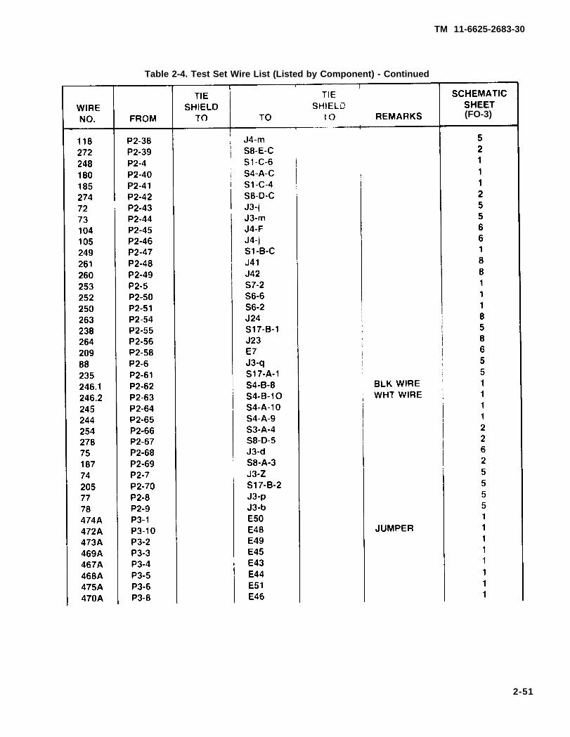
Table 2-4. Test Set Wire List (Listed by Component) - Continued
2-51
TM 11-6625-2683-30
(FO-3)

TM 11-6625-2638-30
Table 2-4. Test Set Wire List (Listed by Component) - Continued
(FO-3)
2-52

TM 11-6625-2638-30
WIRENO.
379338325369541345326380336329374339375409340330372341
3214
12829446018218318446446429329213249461462460461463185463284462248
Table 2-4. Test Set Wire List (Listed by Component) - Continued
FROM
R4-AR4-BR5-AR5-AR5-AR5-BR6-AR6-AR6-BR7-AR7-AR7-BR8-AR8-AR8-BR9-AR9-AR9-BS1-A-3S1-A-4S1-A-5S1-A-6S1-A-6S1-A-CS1-A-CS1-B-1S1-B-2S1-B-3S1-B-3S1-B-4S1-B-4S1-B-6S1-B-CS1-B-CS1-C-l
S1-C-1S1-C-2S1-C-2S1-C-3S1-C-4S1-C-4S1-C-5S1-C-5S1-C-5
TIESHIELD
TO TO
J6-13S20-B-4S20-A-1J6-5CR3-CS20-B-1S20-A-2J6-14S20-B-2S20-A-5J6-7S20-B-5J6-8S20-A-6S20-B-6S20-A-8C1-AS20-B-8J1-EEJ1-HHJ1-PPJ1-dJ5-mS4-A-1S1-C-2P1-24P1-25P1-21S1-B-4S1-B-3S4-B-5S16-A-6J1-uP2-47S1-C-2S1-C-5S1-A-CS1-C-1S1-C-4P2-41S1-C-3S2-A-XS1-C-1P2-4
TIESHIELD
TO REMARKS
JUMPER
JUMPERJUMPER
JUMPERJUMPERJUMPERJUMPERJUMPER
JUMPER
JUMPER
SCHEMATICSHEET(FO-3)
77777777777777777711111111111111111111111111
2-53

TM 11-6625-2638-30
WIRENO.
291404403300226227.2227.3227.1301230290370214477478477479479490289490232478491491492492493493494243241.2495496494497495239.2496497498159.1161.1241.1
Table 2-4. Test Set Wire List (Listed by Component) - Continued
FROM
S1-C-CS10-1S1O-2S11-1S11-2S12-1S12-2S12-3S13-1S13-2S14-1S14-1S14-2S15-A-1S15-A-1S15-A-3S15-A-3S15-A-4S15-A-4S15-A-6S15-A-6S15-A-CS15-B-2S15-B-2S15-B-3S15-B-3S15-B-5S15-B-5S15-B-6S15-B-6S15-B-CS15-C-1S15-C-1S15-C-2S15-C-3S15-C-3S15-C-4S15-C-5S15-C-5S15-C-6S15-C-6S15-C-CS15-C-CS15-D-1
TIESHIELD
TO TO
C2-AK1-X2S9-NOJ12P1-65P1-63P1-33P1-62S16-B-cP1-35S7-1S20-A-1P1-4S15-A-3S15-B-2S15-A-1S15-A-4S15-A-3S15-A-6S7-3S15-A-4P1-67S15-A-1S15-B-3S15-B-2S15-B-5S15-B-3S15-B-6S15-B-5S15-c-3P1-66P1-59S15-C-4S15-C-5S15-B-6S15-C-6S15-C-1P1-60S15-C-2S15-C-3S15-D-3J5-ZJ5-dP1-58
TIESHIELD
TO REMARKS
WHT WIRERED WIREBLK WIRE
JUMPERJUMPERJUMPERJUMPERJUMPERJUMPER
JUMPER
JUMPERJUMPERJUMPERJUMPERJUMPERJUMPERJUMPERJUMPER
WHT WIREJUMPERJUMPERJUMPERJUMPERJUMPERWHT WIREJUMPERJUMPERJUMPERBLK WIREBLK WIREBLK WIRE
SCHEMATICSHEET(FO-3)
13333333333335555555555555555555555555555555
2-54
TM 11-6625-2638-30
WIRENO.
499500498501499239.1500501324159.2161.2202509509323322203502292502503503504504512321266267510510511511301513513514514515515516516517302
Table 2-4. Test Set Wire List (Listed by Component) - Continued
FROM
S15-D-1S15-D-2S15-D-3S15-D-3S15-D-4S15-D-5S15-D-5S15-0-6S15-D-6S15-D-CS15-D-CS16-A-10S16-A-1OS16-A-11S16-A-11S16-A-12S16-A-3S16-A-3S16-A-6S16-A-6S16-A-6S16-A-7S16-A-7S16-A-8S16-A-CS16-B-12S16-B-2S16-B-3S16-B-3S16-B-7S16-B-7S16-B-8S16-B-CS16-C-3S16-C-4S16-C-4S16-C-5S16-C-5S16-C-6S16-C-6S16-C-7S16-C-7S16-C-8
TIESHIELD
TO TO
S15-D-4S15-D-5S15-C-6S15-D-6S15-D-1P1-61S15-D-2S15-D-3E6J5-aJ5-cP1-55S16-A-11S16-A-1OS18-A-11S18-A-CP1-23S16-A-6S1-B-6S16-A-3S16-A-7S16-A-6S16-A-8S16-A-7S16-C-CS18-B-CP2-3P1-70S16-B-7S16-B-3S16-B-8S16-B-7S13-1S16-C-4S16-C-3S16-C-5S16-C-4S16-C-6S16-C-5S16-C-7S16-C-6S16-C-8S4-B-C
TIESHIELD
TO REMARKS
JUMPERJUMPERJUMPERJUMPERJUMPERBLK WIREJUMPERJUMPER
WHT WIREWHT WIRE
JUMPERJUMPER
JUMPER
JUMPERJUMPERJUMPERJUMPERJUMPERJUMPER
JUMPERJUMPERJUMPERJUMPER
JUMPERJUMPERJUMPERJUMPERJUMPERJUMPERJUMPERJUMPERJUMPER
SCHEMATICSHEET(FO-3)
5555555555566666666666666666666666666666666
2-55
TM 11-6625-2638-30
WIRENO.
517512235233.2233.152120752252252127523820523752320652452352411927350850850776507506506505505277527323527204526525201525526322165528
Table 2-4. Test Set Wire List (Listed by Component) - Continued
FROM
S16-C-8S16-C-CS17-A-1S17-A-2S17-A-3S17-A-3S17-A-4S17-A-4S17-A-5S17-A-6S17-A-CS17-B-1S17-B-2S17-B-3S17-B-3S17-B-4S17-B-4S17-B-5S17-B-6S17-B-CS17-C-1S17-C-1S17-C-2S17-C-2S17-C-3S17-C-4S17-C-4S17-C-5S17-C-5S17-C-6S17-C-CS18-A-1OS18-A-11S18-A-11S18-A-2S18-A-2S18-A-3S18-A-8S18-A-8S18-A-9S18-A-cS18-B-3S18-B-3
TIESHIELD
TO TO
S16-C-7S16-A-CP2-61P2-27P2-30S17-A-6P1-6S17-A-5S17-A-4S17-A-3P2-36P2-55P2-70P2-34S17-B-5P1-5S17-B-6S17-B-3S17-B-4J4-JP2-37S17-C-2S17-C-1S17-C-4J3-TS17-C-2S17-C-5S17-C-4S17-C-6S17-C-5TB1-11S18-A-11S16-A-11S18-A-1OP1-19S18-A-9S18-A-8P1-22S18-A-3S18-A-2S16-A-12J5-HHS18-B-8
TIESHIELD
TO REMARKS
JUMPERJUMPER
WHT WIREBLK WIREJUMPER
JUMPERJUMPERJUMPER
JUMPER
JUMPERJUMPERJUMPER
JUMPERJUMPERJUMPER
JUMPERJUMPERJUMPERJUMPERJUMPER
JUMPER
JUMPER
JUMPERJUMPER
JUMPERJUMPER
JUMPER
SCHEMATICSHEET(FO-3)
6655555555555555555555555555555666666666666
2-56

TM 11-6625-2638-30
Table 2-4. Test Set Wire List (Listed by Component) - Continued
WIRENO.
20052832135848318377357458A459A460A461 A462A463A464A465A466A161514284458186465465191817458459466222120459285466286370325332333
FROM
S18-B-8S18-B-8S18-B-CS19-1S19-2S19-2S19-2S19-3S2S2S2S2S2S2S2S2S2S2-A-1S2-A-2S2-A-4S2-A-XS2-A-XS2-A-YS2-A-YS2-A-YS2-B-1S2-B-2S2-B-4S2-B-XS2-B-XS2-B-YS2-C-1S2-C-2S2-C-4S2-C-XS2-C-XS2-C-YS2-C-YS20-A-1S20-A-1S20-A-10S20-A-11
TIESHIELD
TO
TIE SCHEMATIC
TOSHIELD SHEET
TO REMARKS (FO-3)
P2-24S18-B-3S16-B-12R20-AJ1-CXDS11-AJ6-10R20-BE43E44E45E46E47E48E49E50E51E45E44E43S1-C-5S2-B-XP2-1S2-A-YS2-A-YE48E47E46S2-A-XS2-C-XS2-C-YE51E50E49S2-B-XS7-3S2-B-YS7-1S14-1R5-AR20-BR11-A
JUMPER
JUMPERJUMPER
JUMPERJUMPERJUMPER
JUMPER
JUMPER
E37
6667777711111111111111111
11111111
11117777
2-57
1
TM 11-6625-2638-30
WIRENO.
283492935014935130352268.331347353323552801725185275185195195205205295295305301794294265315314252802514814725424
Table 2-4. Test Set Wire List (Listed by Component) - Continued
FROM
S21-A-3S21-A-3S21-A-4S21-A-4S21-A-5S21-A-5S21-A-6S21-A-6S21-A-7S21-A-8S21-A-8S21-A-8S21-A-9S21-A-9S21-A-CS21-B-1S21-B-1S21-B-10S21-B-11S21-B-2S21-B-2S21-B-3S21-B-3S21-B-4S21-B-4S21-B-5S21-B-5S21-B-6S21-B-7S21-B-7S21-B-8S21-B-8S21-B-9S21-B-CS3-A-1S3-A-2S3-A-3S3-A-4S3-A-4S3-A-5
TIESHIELD
TO TO
J1-PR14-BJ1-NR15-BJ5-GGR16-BJ1-JR17-BP2-14J1-mR12-BJ43J1-jR19-BS3-A-1J5-fS21-B-2J1-AAJ1-BBS21-B-1S21-B-3S21-B-2S21-B-4S21-B-3S21-B-5S21-B-4S21-B-6S21-B-5J5-XTB1-3R18-AS21-B-9S21-B-8S3-B-1S21-A-CJ1-KJ5-MMJ5-yP2-66J1-y
TIESHIELD
TO REMARKS
RED WIRE*J2-7
*J2-8
JUMPER
JUMPERJUMPERJUMPERJUMPERJUMPERJUMPERJUMPERJUMPERJUMPER
JUMPERJUMPER
SCHEMATICSHEET(FO-3)
8888888888888888888888888888888888222222
2-58

TM 11-6625-2638-30
WIRENO.
223326212327213328329288409268.1346330331334.16634510934364344653361103376233863339106340111268.2107341108342334.236333563435348
Table 2-4. Test Set Wire List (Listed by Component) - Continued
FROM
S20-A-2S20-A-2S20-A-3S20-A-3S20-A-4S20-A-4S20-A-5S20-A-6S20-A-6S20-A-7S20-A-7S20-A-8S2U-A-9S20-A-CS20-B-1S20-B-1S20-B-10S20-B-10S20-B-11S20-B-11S20-B-2S20-B-2S20-B-3S20-B-3S20-B-4S20-B-4S20-B-5S20-B-5S20-B-6S20-B-6S20-B-7S20-B-7S20-B-8S20-B-8S20-B-9S20-B-9S20-B-CS21-A-1S21-A-10S21-A-10S21-A-11S21-A-2S21-A-2
TIESHIELD
TO TO
P2-2R6-AP2-28R3-AP2-29R4-AR7-AS5-3R8-AP2-20J6-25R9-AR10-AJ8J3-DR5-BJ4-LR2-BJ3-XR11-BJ3-CR6-BJ4-dR3-BJ3-LR4-BJ3-KR7-BJ4-ER8-BJ4-kP2-21J4-nR9-BJ4-pR10-BJ7J1-iJ1-nR1-BJ1-CCJ1-MR13-B
TIESHIELD
TO REMARKS
BLK WIRE
BLK WIRE
WHT WIRE* J4-p
*J4-n
WHT WIRE
SCHEMATICSHEET(FO-3)
7777777777777777777777777777777777777888888
*Twist with
2-59
TM 11-6625-2638-30
WIRENO.
23146145144281282425168532532533533534534535535536536537537538538385294245470467471467468431468469471472469470244472180246.2475
Table 2-4. Test Set Wire List (Listed by Component) - Continued
FROM
S3-A-6S3-A-7S3-A-8S3-A-9S3-A-9S3-A-CS3-B-1S3-B-2S3-B-2S3-B-3S3-B-3S3-B-4S3-B-4S3-B-5S3-B-5S3-B-6S3-B-6S3-B-7S3-B-7S3-B-8S3-B-8S3-B-9S3-B-CS4-A-1S4-A-10S4-A-10S4-A-2S4-A-3S4-A-4S4-A-4S4-A-5S4-A-6S4-A-6S4-A-7S4-A-7S4-A-8S4-A-8S4-A-9S4-A-9S4-A-CS4-B-10S4-B-10
TIESHIELD
TO TO
J1-eJ5-gJ5-pJ5-nJ37J10S21-B-CJ5-xS3-B-3S3-B-2S3-B-4S3-B-3S3-B-5S3-B-4S3-B-6S3-B-5S3-B-7S3-B-6S3-B-8S3-B-7S3-B-9S3-B-8J14S1-A-CP2-64S4-A-8S4-A-4S4-A-7S4-A-2S4-A-6S7-1S4-A-4S4-A-8S4-A-3S4-A-9S4-A-6S4-A-10P2-65S4-A-7P2-40P2-63S4-B-6
TIESHIELD
TO
E21
i SCHEMATICSHEET
REMARKS (FO-3)
JUMPERJUMPERJUMPERJUMPERJUMPERJUMPERJUMPERJUMPERJUMPERJUMPERJUMPERJUMPERJUMPERJUMPER
JUMPERJUMPERJUMPERJUMPERJUMPER
JUMPERJUMPERJUMPER
JUMPERJUMPER
WHT WIREJUMPER
222222222222222222222221111111111111111111
2-60

TM 11-6625-2638-30
WIRENO.
474476474293473473475427246.147618130212028825025128725228629043125328528983486824888118780256489488487489283486485485484484483
Table 2-4. Test Set Wire List (Listed by Component) - Continued
FROM
S4-B-2S4-B-2S4-B-4S4-B-5S4-B-5S4-B-6S4-B-6S4-B-7S4-B-8S4-B-8S4-B-CS4-B-CS5-2S5-3S6-2S6-3S6-5S6-6S7-1S7-1S7-1S7-2S7-3S7-3S8-A-1S8-A-1S8-A-2S8-A-2S8-A-3S8-A-3S8-A-4S8-A-4S8-A-4S8-A-5S8-A-5S8-A-6S8-A-CS8-B-1S8-B-1S8-B-2S8-B-2S8-B-3S8-B-3
TIESHIELD
TO TO
S4-B-4S4-B-8S4-B-2S1-B-4S4-B-6S4-B-5S4-B-10P1-18P2-62S4-B-2P1-20S16-C-8J4-KS20-A-6P2-51P1-32J11P2-50S2-C-YS14-1S4-A-5P2-5S2-C-XS15-A-6J3-aS8-B-1J3-fS8-A-5J3-cP2-69J3-YP2-33S8-A-6S8-A-2S8-B-5S8-A-4J9S8-A-1S8-B-2S8-B-1S8-B-3S8-B-2S8-B-4
TIESHIELD
TO REMARKS
JUMPERJUMPERJUMPER
JUMPERJUMPERJUMPER
BLK WIREJUMPER
JUMPER
JUMPER
JUMPERJUMPERJUMPERJUMPER
JUMPERJUMPERJUMPERJUMPERJUMPERJUMPER
SCHEMATICSHEET(FO-3)
1111111111111111111111112222222222222222222
2-61

TM 11-6625-2638-30
WIRENO.
4834874824822552784814812742794804807927226408403299394041424344454647495051606186879092121122123124125167
Table 2-4. Test Set Wire List (Listed by Component) - Continued
FROM
S8-B-4S8-B-5S8-B-5S8-B-6S8-B-CS8-D-5S8-D-5S8-D-6S8-D-CS8-E-5S8-E-5S8-E-6S8-E-CS8-E-CS9-CS9-CS9-NOSI6-B-CSTOWEDSTOWEDSTOWEDSTOWEDSTOWEDSTOWEDSTOWEDSTOWEDSTOWEDSTOWEDSTOWEDSTOWEDSTOWEDSTOWEDSTOWEDSTOWEDSTOWEDSTOWEDSTOWEDSTOWEDSTOWEDSTOWEDSTOWEDSTOWED
TIESHIELD
TO TO
S8-B-3S8-A-5S8-B-6S8-B-5P2-32P2-67S8-D-6S8-D-5P2-42XDS3-AS8-E-6S8-E-5J3-iP2-39J1-qTB1-6S10-2TB1-11J1-NNJ1-wJ1-FFJ1-MMJ1-KKJ1-xJ1-rJ1-DDJ1-fJ1-aJ1-RJ1-LJ2-12J2-11J3-nJ3-hJ3-eJ3-GJ4-eJ4-fJ4-gJ4-TJ4-UJ5-FF
TIESHIELD
TO REMARKS
JUMPERJUMPERJUMPERJUMPER
JUMPERJUMPER
JUMPERJUMPER
SCHEMATICSHEET(FO-3)
22222222222222333
2-62
TM 11-6625-2638-30
WIRENO.
1691701711741751761771784174184194204214224235355540.1295296298842772993893904002253639829742842939839943241541658361539.1408
Table 2-4. Test Set Wire List (Listed by Component) - Continued
FROM
STOWEDSTOWEDSTOWEDSTOWEDSTOWEDSTOWEDSTOWEDSTOWEDSTOWEDSTOWEDSTOWEDSTOWEDSTOWEDSTOWEDSTOWEDTB1-1TB1-ITB1-1TB1-10TB1-10TB1-10TB1-11TB1-11TB1-11TB1-12TB1-12TB1-12TB1-2TB1-2TB1-3TB1-3TB1-3TB1-3TB1-4TB1-4TB1-4TB1-5TB1-5TB1-6TB1-6TB1-6TB1-6
TIESHIELD
TO TO
J5-qJ5-EEJ5-KKJ5-kJ5-SJ5-RJ5-NJ5-MJ6-17J6-18J6-19J6-20J6-21J6-22J6-23J2-8J2-10W5-WHTE5E8E4J3-tS17-C-CS16-B-CE6E1E7P2-19XDS2-BJ4-hE3J6-15S21-B-7R12-AE1E42E18E22J2-2XDS1-BW4-WHTS9-C
TIESHIELD
TO REMARKS
*J2-7*J2-4
* P2-18
* J2-1
SCHEMATICSHEET(FO-3)
222222222222222222222222222
*Twist with
2-63

TM 11-6625-2638-30
WIRENO.
973765456224368113.1539.2539.3539.1540.2540.3540.157365360361309310194317318199316317198315316197314315196313314262312313195311312259
* Twist with
Table 2-4. Test Set Wire List (Listed by Component) - Continued
FROM
TB1-7TB1-7TB1-8TB1-8TB1-8TB1-8TP1W4-BLKW4-GRNW4-WHTW5-BLKW5-GRNW5-WHTXDS1-AXDS1-AXDS1-BXDS1-BXDS1O-AXDS1O-AXDS1O-BXDS11-AXDS11-AXDS11-BXDS12-AXDS12-AXDS12-BXDS13-AXDS13-AXDS13-BXDS14-AXDS14-AXDS14-BXDS15-AXDS15-AXDS15-BXDS16-AXDS16-AXDS16-BXDS17-AXDS17-AXDS17-B
TIESHIELD
TO TO
J4-NJ6-9J2-7J2-4P2-18XDS2-AJ4-WXF1-AE2TB1-6XF2-AE2TB1-1J2-1K1-B1J6-1TB1-6XDS9-AXDS18-AP1-15XDS12-AS19-2P1-10XDS13-AXDS11-AP1-8XDS14-AXDS12-AP1-7XDS15-AXDS13-AP1-9XDS16-AXDS14-AP1-47XDS17-AXDS15-AP1-38XDS18-AXDS16-AP1-45
TIESHIELD
TO REMARKS
*J2-8* J2-1O*P2-19
BLK WIRE
*J2-2
SCHEMATICSHEET(FO-3)
22222282222223333333333333333333333333333
2-64

TM 11-6625-2638-30
Table 2-4. Test Set Wire List (Listed by Component) - Continued
TIE TIE SCHEMATICWIRE SHIELD SHIELD SHEETNO. FROM TO TO TO REMARKS (FO-3)
310 XDS18-A XDS1O-A 3311 XDS18-A XDS17-A 3258 XDS18-B P1-46 3367 XDS2-A K1-A1 3368 XDS2-A TB1-8 3362 XDS2-B J6-2 *J6-4 3363 XDS2-B TB1-2 3279 XDS3-A S8-E-5 3303 XDS3-A XDS4-A 3188 XDS3-B P1-52 3303 XDS4-A XDS3-A 3304 XDS4-A XDS5-A 3189 XDS4-B P1-50 3304 XDS5-A XDS4-A 3305 XDS5-A XDS6-A 3190 XDS5-B P1-44 3305 XDS6-A XDS5-A 3306 XDS6-A XDS7-A 3191 XDS6-B P1-42 3306 XDS7-A XDS6-A 3307 XDS7-A XDS8-A 3257 XDS7-B P1-48 3307 XDS8-A XDS7-A 3308 XDS8-A XDS9-A 3192 XDS8-6 P1-40 3308 XDS9-A XDS8-A 3309 XDS9-A XDS10-A 3193 XDS9-B P1-17 3539.2 XF1-A W4-BLK 2401 XF1-B K1-B2 2402 XF1-B K1-X1 2540.2 XF2-A W5-BLK 2405 XF2-B K1-A2 2
*Twist with
2-65

TM 11-6625-2638-30
WIRENO.
123456789
101112131414A1515A1616A1717A1818A1919A2020A2121A2222A23
Table 2-5. Test Set Wire List (Listed by Wire Number)
FROM
J1-PPJ1-HHJ1-EEJ1-dJ1-cJ1-sJ1-BBJ1-hJ1-LLJ1-zJ1-VJ1-tJ1-uE43J1-pE44J1-YE45J1-XE46J1-WE47J1-ZE48J1-BE49J1-AE50J1-bE51J1-DJ1-e
TIESHIELD
TO TO
S1-A-5S1-A-4S1-A-3S1-A-6E5E5S21-B-11P1-12P1-11P1-13P1-14P2-22S1-B-CS2-A-4E43S2-A-2E44S2-A-1E45S2-B-4E46S2-B-2E47S2-B-1E48S2-C-4E49S2-C-2E50S2-C-1E51S3-A-6
TIESHIELD
TO REMARKS
2-66

TM 11-6625-2638-30
WIRENO.
2425262728293031323334353637383940414243444546474849505152535455565758
Table 2-5. Test Set Wire List (Listed by Wire Number) - (Continued)
FROM
J1-yJ1-KJ1-qJ1-GGJ1-PJ1-NJ1-JJ1-mJ1-jJ1-nJ1-CCJ1-MJ1-iJ1-kJ1-JJJ1-NNJ1-wJ1-FFJ1-MMJ1-KKJ1-xJ1-rJ1-DDJ1-fJ1-CJ1-aJ1-RJ1-LJ1-AAJ2-8J2-7J2-10J2-4J2-1J2-2
TIESHIELD
TO TO
S3-A-5S3-A-2S9-CP1-39S21-A-3S21-A-4S21-A-6S21-A-8S21-A-9S21-A-10S21-A-11S21-A-2S21-A-1R19-AJ34STOWEDSTOWEDSTOWEDSTOWEDSTOWEDSTOWEDSTOWEDSTOWEDSTOWEDS19-2STOWEDSTOWEDSTOWEDS21-B-10TB1-1TB1-8TB1-1TB1-8XDS1-ATB1-6
TIESHIELD
TO REMARKS
*J2-7*J2-8
*J2-7*J2-8*J2-4*J2-10*J2-2*J2-1
* Twist with
2-67

TM 11-6625-2638-30
WIRENO.
5960616263646566676869707172737475767778798081828384858687888990919293
Table 2-5. Test Set Wire List (Listed by Wire Number) - (Continued)
FROM
J2-5J2-12J2-11J3-LJ3-KJ3-XJ3-CJ3-DJ3-JJ3-HJ3-EJ3-FJ3-sJ3-jJ3-mJ3-ZJ3-dJ3-TJ3-pJ3-bJ3-iJ3-YJ3-cJ3-fJ3-aJ3-tJ3-kJ3-nJ3-hJ3-qJ3-gJ3-eJ3-RJ3-GJ4-Z
TIESHIELD
TO TO
E3STOWEDSTOWEDS20-B-4S20-B-5S20-B-11S20-B-2S20-B-1J26J27J29J31J32P2-43P2-44P2-7P2-68S17-C-3P2-8P2-9S8-E-CS8-A-4S8-A-3S8-A-2S8-A-1TB1-11P2-35STOWEDSTOWEDP2-6J16STOWEDP2-31STOWEDE4
TIESHIELD
TO
E27
E-27
E26
REMARKS
2-68

TM 11-6625-2638-30
WIRENO.
949596979899
100.1101.2102.1102.2104105106107108109110111112113.1113.2114115116117118119120121122123124125126127
Table 2-5. Test Set Wire List (Listed by Wire Number) – (Continued)
FROM
J4-HJ4-tJ4-qJ4-NJ4-hJ4-AJ4-YJ4-XJ4-rJ4-sJ4-FJ4-jJ4-EJ4-nJ4-pJ4-LJ4-dJ4-kJ4-MJ4-WJ4-VJ4-DJ4-CJ4-iJ4-GJ4-mJ4-JJ4-KJ4-eJ4-fJ4-gJ4-TJ4-U
J5-D
TIESHIELD
TO TO
E4J6-24J6-11TB1-7TB1-3E3P1-1P1-36P1-3P1-2P2-45P2-46S20-B-6S20-B-8S20-B-9S20-B-10S20-B-3S20-B-7J11TP1J25J28J30J41J42P2-38S17-B-CS5-2STOWEDSTOWEDSTOWEDSTOWEDSTOWED
E3
TIESHIELD
TO
E31
E31
E23E23
E35
REMARKS
BLK WIREWHT WIREBLK WIREWHT WIRE
*J4-/P*J4-/N
BLK WIREWHT WIRE
* Twist with
2-69
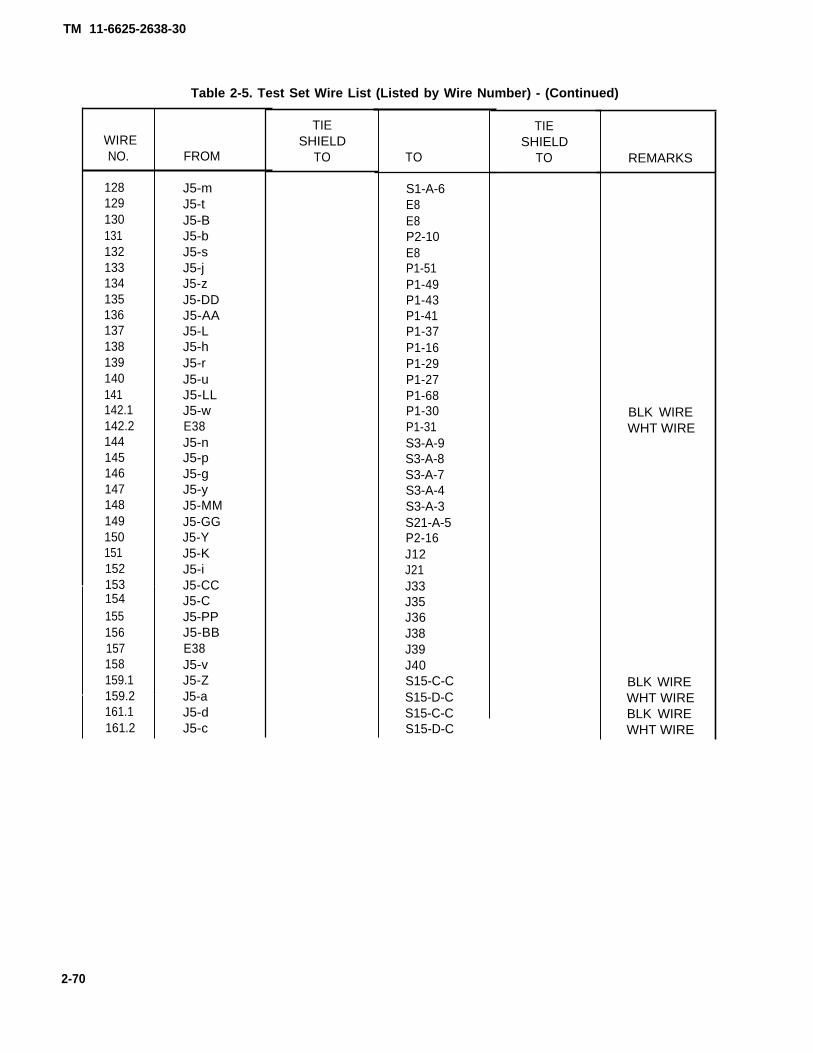
TM 11-6625-2638-30
WIRENO.
128129130131132133134135136137138139140141142.1142.2144145146147148149150151152153154155156157158159.1159.2161.1161.2
Table 2-5. Test Set Wire List (Listed by Wire Number) - (Continued)
FROM
J5-mJ5-tJ5-BJ5-bJ5-sJ5-jJ5-zJ5-DDJ5-AAJ5-LJ5-hJ5-rJ5-uJ5-LLJ5-wE38J5-nJ5-pJ5-gJ5-yJ5-MMJ5-GGJ5-YJ5-KJ5-iJ5-CCJ5-CJ5-PPJ5-BBE38J5-vJ5-ZJ5-aJ5-dJ5-c
TIESHIELD
TO TO
S1-A-6E8E8P2-10E8P1-51P1-49P1-43P1-41P1-37P1-16P1-29P1-27P1-68P1-30P1-31S3-A-9S3-A-8S3-A-7S3-A-4S3-A-3S21-A-5P2-16J12J21J33J35J36J38J39J40S15-C-CS15-D-CS15-C-CS15-D-C
TIESHIELD
TO REMARKS
BLK WIREWHT WIRE
BLK WIREWHT WIREBLK WIREWHT WIRE
2-70

TM 11-6625-2638-30
WIRENO.
163164165166167168169170171172173174175176177178179180181182183184185186187188189190191192193194195196197
Table 2-5. Test Set Wire List (Listed by Wire Number) - (Continued)
FROM
J5-AJ5-NNJ5-HHJ5-JJ5-FFJ5-xJ5-qJ5-EEJ5-KKJ5-fJ5-eJ5-kJ5-SJ5-RJ5-NJ5-MJ5-XP2-40P1-20P1-24P1-25P1-21P2-41P2-1P2-69P1-52P1-50P1-44P1-42P1-40P1-17P1-15P1-38P1-9P1-7
TIESHIELD
TO TO
P1-26P1-28S18-B-3P1-57STOWEDS3-B-2STOWEDSTOWEDSTOWEDS21-B-1E39STOWEDSTOWEDSTOWEDSTOWEDSTOWEDS21-B-7S4-A-CS4-B-CS1-B-1S1-B-2S1-B-3S1-C-4S2-A-YS8-A-3XDS3-BXDS4-BXDS5-BXDS6-BXDS8-BXDS9-BXDS10-BXDS16-BXDS14-BXDS13-B
TIESHIELD
TO REMARKS
2-71

TM 11-6625-2638-30
WIRENO.
198199200201202203204205206207208209210211212213214215216217218219220221222223224225226227.1227.2227.3230231232
Table 2-5. Test Set Wire List (Listed by Wire Number) - (Continued)
FROM
P1-8P1-10P2-24P1-22P1-55P1-23P1-19P2-70P1-5P1-6P2-23P2-58
P2-28P2-29P1-4J3-S
P2-11P2-2P2-18P2-19P1-65P1-62P1-63P1-33P1-35P2-12P1-67
TIESHIELD
TO
E32E30E30E32E27E31E31
E28E28
E41E23
TO
XDS12-BXDS11-BS18-B-8S18-A-8S16-A-10S16-A-3S18-A-2S17-B-2S17-B-4S17-A-4C2-AE7
S20-A-3S20-A-4S14-2E3
E7S20-A-2TB1-8TB1-2S11-2S12-3S12-1S12-2S13-2R11-AS15-A-C
TIESHIELD
TO
E37
REMARKS
*P2-19*P2-18
BLK WIREWHT WIRERED WIRE
2-72

TM 11-6625-2638-30
WIRENO.
233.1233.2235236237238239.1239.2241.1241.2243244245246.1246.2248249250251252253254255256257258259260261262263264265266267
Table 2-5. Test Set Wire List (Listed by Wire Number) - (Continued)
FROM
P2-30P2-27P2-61P1-64P2-34P2-55P1-61P1-60P1-58P1-59P1-66P2-65P2-64P2-62P2-63P2-4P2-47P2-51P1-32P2-50P2-5P2-66P2-32P2-33P1-48P1-46P1-45P2-49P2-48P1-47P2-54P2-56P1-34P2-3P1-70
TIESHIELD
TO TO
S17-A-3S17-A-2S17-A-1J35S17-B-3S17-B-1S15-D-5S15-C-5S15-D-1S15-C-1S15-B-CS4-A-9S4-A-10S4-B-8S4-B-10S1-C-6S1-B-CS6-2S6-3S6-6S7-2S3-A-4S8-B-CS8-A-4XDS7-BXDS18-BXDS17-BJ42J41XDS15-BJ24J23J40S16-B-2S16-B-3
TIESHIELD
TO REMARKS
BLK WIREWHT WIRE
BLK WIREWHT WIREBLK WIREWHT WIRE
BLK WIREWHT WIRE
2-73

TM 11-6625-2638-30
WIRENO.
268.1268.2268.3271272273274275277278279280281282283284285286287288289290291292293294295296297298299300301302303
Table 2-5. Test Set Wire List (Listed by Wire Number) - (Continued)
FROM
P2-20P2-21P2-14P1-69P2-39P2-37P2-42P2-36S17-C-CP2-67XDS3-AS3-A-1S3-A-9S3-A-CS8-A-CS2-A-XS2-C-XS2-C-YS6-5S5-3S7-3S7-1S1-C-CS1-B-6S1-B-4S1-A-CE5E8E3E4TB1-11S11-1S13-1S4-B-CXDS3-A
TIESHIELD
TO TO
S20-A-7S20-B-7S21-A-7J22S8-E-CS17-C-1S8-D-CS17-A-CTB1-11S8-D-5S8-E-5S21-A-CJ37J10J9S1-C-5S7-3S7-1J11S20-A-6S15-A-6S14-1C2-AS16-A-6S4-B-5S4-A-1TB1-10TB1-10TB1-3TB1-10S16-B-CJ12S16-B-CS16-C-8XDS4-A
TIESHIELD
TO REMARKS
BLK WIREWHT WIRERED WIRE
2-74
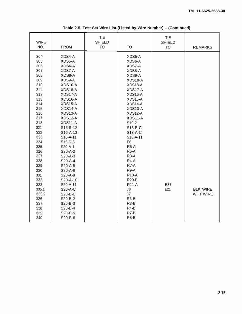
TM 11-6625-2638-30
WIRENO.
304305306307308309310311312313314315316317318321322323324325326327328329330331332333335.1335.2336337338339340
Table 2-5. Test Set Wire List (Listed by Wire Number) – (Continued)
FROM
XDS4-AXDS5-AXDS6-AXDS7-AXDS8-AXDS9-AXDS10-AXDS18-AXDS17-AXDS16-AXDS15-AXDS14-AXDS13-AXDS12-AXDS11-AS16-B-12S16-A-12S16-A-11S15-D-6S20-A-1S20-A-2S20-A-3S20-A-4S20-A-5S20-A-8S20-A-9S20-A-10S20-A-11S20-A-CS20-B-CS20-B-2S20-B-3S20-B-4S20-B-5S20-B-6
TIESHIELD
TO TO
XDS5-AXDS6-AXDS7-AXDS8-AXDS9-AXDS10-AXDS18-AXDS17-AXDS16-AXDS15-AXDS14-AXDS13-AXDS12-AXDS11-AS19-2S18-B-CS18-A-CS18-A-11E6R5-AR6-AR3-AR4-AR7-AR9-AR10-AR20-BR11-AJ8J7R6-BR3-BR4-BR7-BR8-B
TIESHIELD
TO
E37E21
REMARKS
BLK WIREWHT WIRE
2-75

TM 11-6625-2638-30
WIRENO.
341342343344345346347348349350351352353354355356357358359360361362363364365366367368369370371372373374375
Table 2-5. Test Set Wire List (Listed by Wire Number) - (Continued)
FROM
S20-B-8S20-B-9S20-B-10S20-B-11S20-B-1S20-A-7S21-A-8S21-A-2S21-A-3S21-A-4S21-A-5S21-A-6S21-A-8J43S21-A-9S21-A-10S19-3S19-1R20-BJ6-1XDS1-BJ6-2XDS2-BJ6-3K1-B1J6-4K1-A1XDS2-AJ6-5S14-1J6-6C1-AC1-BJ6-7J6-8
TIESHIELD
TO TO
R9-BR10-BR2-BR11-BR5-BJ6-25R12-BR13-BR14-BR15-BR16-BR17-BJ43R18-BR19-BR1-BR20-BR20-AR2-AXDS1-BTB1-6XDS2-BTB1-2CR2-CXDS1-AK1-A1XDS2-ATB1-8R5-AS20-A-1C1-AR9-AR10-AR7-AR8-A
TIESHIELD
TO REMARKS
*J6-4
*J6-2
*Twist with
2-76

TM 11-6625-2638-30
WIRENO.
376377378379380381382383384385386387388389390391392393394395396397398399400401402403404405406408409410411
Table 2-5. Test Set Wire List (Listed by Wire Number) - (Continued)
FROM
J6-9J6-10J6-12J6-13J6-14J6-16C2-BE6J13J14E6J17J10E6E1R19-AR1-AR17-AR16-AR15-AR14-AR13-AR12-AE1E7XF1-BXF1-BS9-NOS10-1XF2-BE1TB1-6S20-A-6E19E21
TIESHIELD
TO TO
TB1-7S19-2R3-AR4-AR6-AE2E6J13J14S3-B-CJ17J18J15TB1-12TB1-12R18-AR17-AR16-AR15-AR14-AR13-AR12-ATB1-4TB1-4TB1-12K1-B2K1-X1S11-2K1-X2K1-A2E2S9-CR8-AE18E22
TIESHIELD
TO REMARKS
2-77

TM 11-6625-2638-30
WIRENO.
412413414415416417418419420421422423424425426427428429430431432433434435436437438439440441442443444445446
Table 2-5. Test Set Wire List (Listed by Wire Number) - (Continued)
FROM
E17E14E13E18E22J6-17J6-18J6-19J6-20J6-21J6-22J6-23CR2-AS3-B-1R18-AP1-18J6-15S21-B-7E38S7-1E42E23E24E25E26E27E28E29E30E31E32E12E15E9E10
TIESHIELD
TO TO
E22E22E22TB1-5TB1-5STOWEDSTOWEDSTOWEDSTOWEDSTOWEDSTOWEDSTOWEDK1-B1S21-B-CS21-B-8S4-B-7TB1-3TB1-3J5-JJS4-A-5TB1-4E33E33E33E33E33E40E40E34E34E34E19E19E19E19
TIESHIELD
TO REMARKS
2-78

TM 11-6625-2638-30
WIRENO.
447448449450451452453454455456457458458A459459A460460A461461 A462462A463463A464464A465465A466466A467467A468468A469469A
Table 2-5. Test Set Wire List (Listed by Wire Number) - (Continued)
FROM
E11E16E7E7E7E40E18E20E35E36E37S2-A-XE43S2-B-XE44S1-A-CE45S1-C-2E46S1-C-1E47S1-C-3E48S1-B-3E49S2-A-YE50S2-B-YE51S4-A-2E43S4-A-4E44S4-A-6E45
TIESHIELD
TO TO
E19E18E33E34E40E41E39E42E42E42E42S2-B-XS2S2-C-XS2S1-C-2S2S1-C-1S2S1-C-5S2S1-C-4S2S1-B-4S2S2-A-YS2S2-C-YS2S4-A-4P3-4S4-A-6P3-5S4-A-8P3-3
TIESHIELD
TO REMARKS
JUMPER
JUMPER
JUMPER
JUMPER
JUMPER
JUMPER
JUMPER
JUMPER
JUMPER
JUMPER
JUMPER
JUMPER
2-79
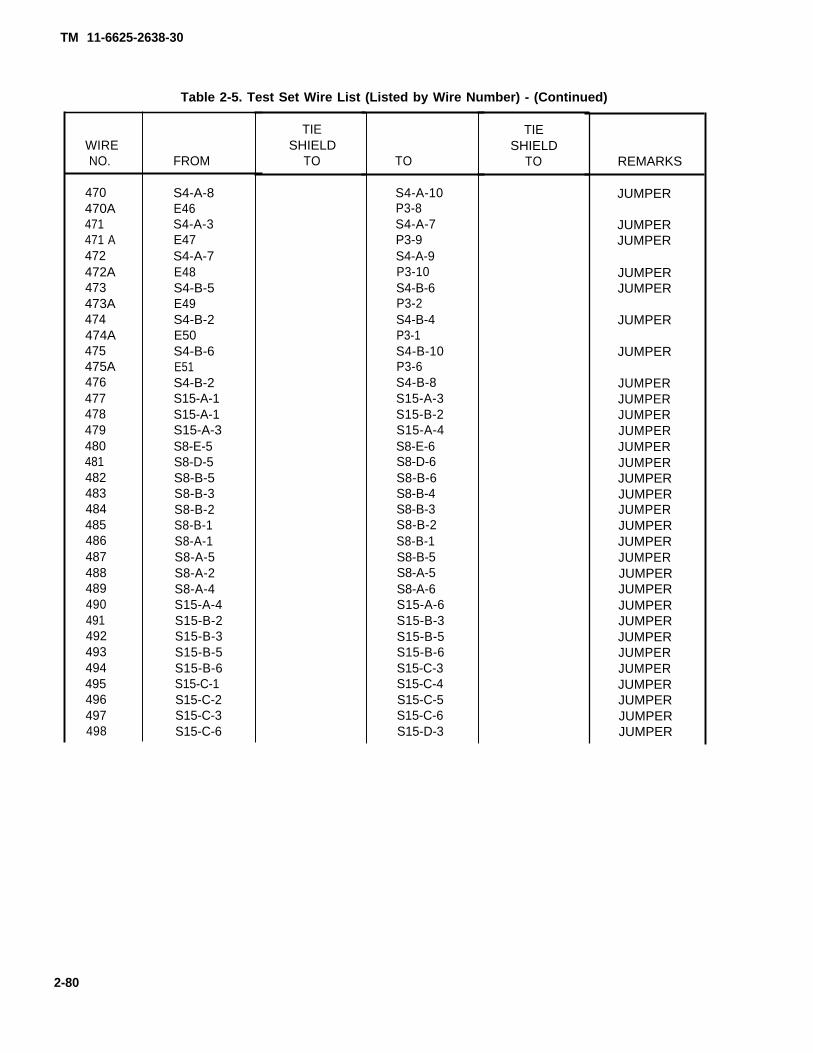
TM 11-6625-2638-30
WIRENO.
470470A471471 A472472A473473A474474A475475A476477478479480481482483484485486487488489490491492493494495496497498
Table 2-5. Test Set Wire List (Listed by Wire Number) - (Continued)
FROM
S4-A-8E46S4-A-3E47S4-A-7E48S4-B-5E49S4-B-2E50S4-B-6E51S4-B-2S15-A-1S15-A-1S15-A-3S8-E-5S8-D-5S8-B-5S8-B-3S8-B-2S8-B-1S8-A-1S8-A-5S8-A-2S8-A-4S15-A-4S15-B-2S15-B-3S15-B-5S15-B-6S15-C-1S15-C-2S15-C-3S15-C-6
TIESHIELD
TO TO
S4-A-10P3-8S4-A-7P3-9S4-A-9P3-10S4-B-6P3-2S4-B-4P3-1S4-B-10P3-6S4-B-8S15-A-3S15-B-2S15-A-4S8-E-6S8-D-6S8-B-6S8-B-4S8-B-3S8-B-2S8-B-1S8-B-5S8-A-5S8-A-6S15-A-6S15-B-3S15-B-5S15-B-6S15-C-3S15-C-4S15-C-5S15-C-6S15-D-3
TIESHIELD
TO REMARKS
JUMPER
JUMPERJUMPER
JUMPERJUMPER
JUMPER
JUMPER
JUMPERJUMPERJUMPERJUMPERJUMPERJUMPERJUMPERJUMPERJUMPERJUMPERJUMPERJUMPERJUMPERJUMPERJUMPERJUMPERJUMPERJUMPERJUMPERJUMPERJUMPERJUMPERJUMPER
2-80

TM 11-6625-2638-30
WIRENO.
499500501502503504505506507508509510511512513514515516517518519520521522523524525526527528529530531532533
Table 2-5. Test Set Wire List (Listed by Wire Number) - (Continued)
FROM
S15-D-1S15-D-2S15-D-3S16-A-3S16-A-6S16-A-7S17-C-5S17-C-4S17-C-2S17-C-1S16-A-10S16-B-3S16-B-7S16-A-CS16-C-3S16-C-4S16-C-5S16-C-6S16-C-7S21-B-1S21-B-2S21-B-3S17-A-3S17-A-4S17-B-3S17-B-4S18-A-3S18-A-2S18-A-10S18-B-3S21-B-4S21-B-5S21-B-8S3-B-2S3-B-3
TIESHIELD
TO TO
S15-D-4S15-D-5S15-D-6S16-A-6S16-A-7S16-A-8S17-C-6S17-C-5S17-C-4S17-C-2S16-A-11S16-B-7S16-B-8S16-C-CS16-C-4S16-C-5S16-C-6S16-C-7S16-C-8S21-B-2S21-B-3S21-B-4S17-A-6S17-A-5S17-B-5S17-B-6S18-A-8S18-A-9S18-A-11S18-B-8S21-B-5S21-B-6S21-B-9S3-B-3S3-B-4
TIESHIELD
TO REMARKS
JUMPERJUMPERJUMPERJUMPERJUMPERJUMPERJUMPERJUMPERJUMPERJUMPERJUMPERJUMPERJUMPERJUMPERJUMPERJUMPERJUMPERJUMPERJUMPERJUMPERJUMPERJUMPERJUMPERJUMPERJUMPERJUMPERJUMPERJUMPERJUMPERJUMPERJUMPERJUMPERJUMPERJUMPERJUMPER
2-81

TM 11-6625-2638-30
Table 2-5. Test Set Wire List (Listed by Wire Number) - (Continued)
WIRENO.
534535536537538539.1539.2539.3540.1540.2540.3541
FROM
S3-B-4S3-B-5S3-B-6S3-B-7S3-B-8W4-WHTW4-BLKW4-GRNW5-WHTW5-BLKW5-GRNR5-A
TIESHIELD
TO TO
S3-B-5S3-B-6S3-B-7S3-B-8S3-B-9TB1-6XF1-AE2TB1-1XF2-AE2CR3-C
TIESHIELD
TO REMARKS
JUMPERJUMPERJUMPERJUMPERJUMPER
2-82

TM 11-6625-2638-30
Table 2-6. Cable Assembly W1 Wire List
WIRENO.
123456789101112131415161718192021222324252627
28293031323334353637383940414243
FROM
P2-1P2-2P2-3P2-4P2-5P2-6P2-7P2-8P2-9P2-10P2-11P2-12P2-13P2-14P2-15P2-16P2-20P2-18P2-19P2-17P2-21P2-22P2-23P2-24P2-25P2-26P2-27
P2-28P2-29P2-39P2-31P2-32P2-33P2-34P2-35P2-36P2-37P2-38P3-6P3-12P3-27P3-7P3-9
TO
P1-HHP1-NNP1-PPP1-JJP1-wP1-vP1-GGP1-FFP1-EEP1-MMP1-KKP1-YP1-xP1-eP1-dP1-cP1-uP1-tP1-sP1-rP1-qP1-pP1-DDP1-LLP1-zP1-hP1-g
P1-fP1-DP1-CP1-BP1-AP1-bP1-aP1-zP1-YP1-xP1-wP1-mP1-kP1-jP1-AAP1-BB
REMARKS
TW WITH 17TW WITH 16TW WITH 19TW WITH 18
TW WITH 40 & 41TW WITH 39 & 41TW WITH 39 & 40
TW WITH 44
WIRENO.
44454647484950515253
54 WHT54 BLK55 WHT55 BLK
5657
58 WHT58 BLK
5960
61 WHT61 BLK62 WHT62 BLK63 WHT63 BLK64 WHT64 BLK64 BLK65 WHT
6667 WHT67 BLK
6869 WHT69 BLK70 WHT70 BLK71 WHT71 BLK
72737475
FROM
P3-10P3-IIP3-13P3-15P3-16P3-18P3-19P3-32P3-1P3-2P3-34P3-35P3-3P3-8P3-4P3-5P3-14P3-17P3-20P3-21P3-22P3-37P3-23P3-24P3-25P3-26P3-28P3-33P3-33P3-29P3-30P3-40P3-41P3-38P3-39P3-44P3-42P3-43P3-54P3-55
P2-41P2-42P2-48
TO
P1-ccP1-nP1-RP1-PP1-NP1-MP1-LP1-KP1-JP1-iP5-HHP5-NNP5-JJP5-wP5-vP5-GGP5-FFP5-PPP5-xE3P5-dP5-cP5-uP5-tP5-sP5-rP5-EEP5-MMP5-MMP5-KKP5-fP5-eP5-CP5-BP5-AP5-bP5-aP5-ZP5-YP5-X
P5-pP5-DDP5-n
REMARKS
TW WITH 44
TIE SH TO E1 & E4
TIE SH TO E1 & E4
TIE SH TO E1 & E4
TIE SH TO E1 & E4
TIE SH TO E1 & E4
TIE SH TO E2 & E5
TIE SH TD E2 & E5
TIE SH TO E2 & E5
TIE SH TO E2 & E5
TIE SH TO E3 & E6
TIE SH TO E3 & E6
TIE SH TO E3 & E6
2-83

TM 11-6625-2638-30
Table 2-6. Cable Assembly W1 Wire List - Continued
WIRE WIRENO. FROM TO REMARKS NO. FROM TO REMARKS
76 P2-51 P5-CC 89 P3-46 P5-S77 P3-48 P5-m 9078 P3-49 P5-LL TIE SH TO E7 & E7 9179 P3-52 P5-BB TIE SH TO E7 & E8 9280 P3-53 P5-k 9381 P2-43 P5-AA 94 P2-52 P5-L TIE SH TO E7 & E782 P2-50 P5-j 95 P5-D E783 P2-44 P5-z 96 E1 E284 P2-49 P5-i 97 E2 E385 P2-45 P5-g 98 E4 E586 P2-46 P5-h 99 E5 E687 P2-47 P5-K TIE SH TO E7 & E8 100 E6 E788 P3-47 P5-J 101 E3 E8
2-84
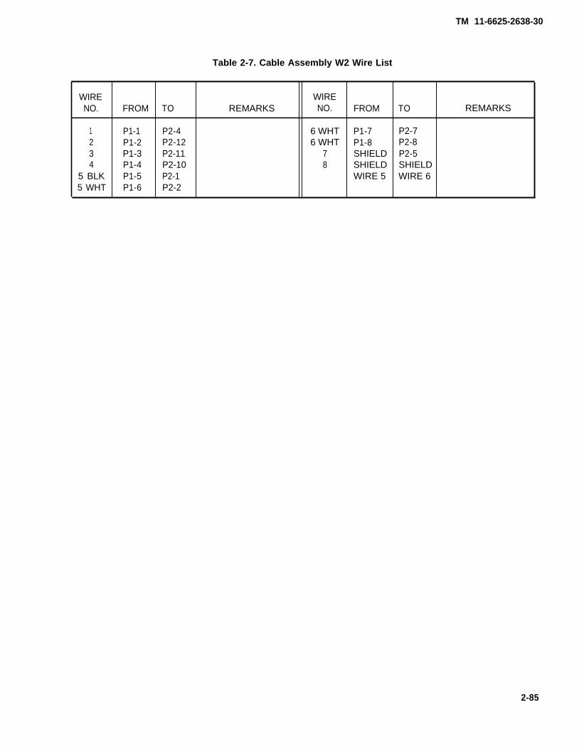
TM 11-6625-2638-30
Table 2-7. Cable Assembly W2 Wire List
WIRE WIRENO. FROM TO REMARKS NO. FROM TO REMARKS
1 P1-1 P2-4 6 WHT P1-7 P2-72 P1-2 P2-12 6 WHT P1-8 P2-83 P1-3 P2-11 7 SHIELD P2-54 P1-4 P2-10 8 SHIELD SHIELD
5 BLK P1-5 P2-1 WIRE 5 WIRE 65 WHT P1-6 P2-2
2-85

Table 2-8. Cable Assembly W3 Wire List
WIRE WIRENO. FROM TO REMARKS NO. FROM TO REMARKS
1 P1-6 P3-t 28 WHT P2-1 P4-t TIE SH TO E5 & E72 P1-15 P3-Y 28 BLK P2-18 P4-k3 E3 E4 29 WHT P2-4 P4-m TIE SH TO E5 & E74 P1-5 P3-s 29 BLK P2-5 P4-Z5 E5 E6 30 WHT P2-9 P4-X TIE SH TO E5 & E7
6 WHT P1-2 P3-m TIE SH TO E1 & E3 30 BLK P2-10 P4-Y6 BLK P1-1 P3-j 31 WHT P2-11 P4-r TIE SH TO E5 & E77 WHT P1-12 P3-n TIE SH TO E1 & E3 31 BLK P2-15 P4-s7 BLK P1-36 P3-X 32 P2-12 P4-q TW/ WITH 33 & 347 RED P1-4 P3-k 33 P2-13 P4-p TW WITH 32 & 34
8 E7 E8 34 P2-14 P4-n TW WITH 32 & 339 WHT P1-21 P3-q TIE SH TO E1 & E3 35 P2-22 P4-d9 BLK P1-20 P3-Z 36 P2-24 P4-e
10 WHT P1-35 P3-b TIE SH TO E1 & E3 37 P2-25 P4-f10 BLK P1-33 P3-p 38 P2-26 P4-g11 WHT P1-10 P3-h TIE SH TO E2 & E4 39 P2-27 P4-h11 BLK P1-29 P3-1 40 WHT P2-30 P4-i TIE SH TO E5 & E711 RED P1-31 P3-T 40 BLK P2-31 P4-j12 WHT P1-13 P3-f TIE SH TO E2 & E4 41 WHT P2-32 P4-F TIE SH TO E6 & E812 BLK P1-26 P3-R 41 BLK P2-33 P4-G13 WHT P1-18 P3-c TIE SH TO E2 & E4 42 P2-34 P4-C13 BLK P1-28 P3-d 43 P2-35 P4-D
14 P1-22 P3-g 44 P2-36 P4-E15 P1-23 P3-e 45 P2-40 P4-N16 P1-30 P3-a 46 WHT P2-41 P4-H TIE SH TO E6 & E817 P1-25 E2 46 BLK P2-42 P4-J18 E4 P3-S 47 P2-43 P4-K19 P2-2 P3-C 48 P2-45 P4-L20 P2-3 P3-D 49 P2-46 P4-M TIE SH TO E6 & E821 P2-6 P3-E 50 P2-47 P4-T TW WITH 5122 P2-7 P3-F 51 P2-48 P4-U TW WITH 5023 P2-8 P3-G 52 WHT P2-49 P4-V TIE SH TO E6 & E824 P2-16 P3-H 52 BLK P2-50 P4-W25 P2-17 P3-J 53 P2-39 E526 P2-19 P3-K 54 E7 P4-A27 P2-21 P3-L 55 E1 E2
2-86
TM 11-6625-2638-30

TM 11-6625-2638-30
Section VI. PREPARATION FOR STORAGE OR SHIPMENT
2-25. Preparing Test Set for Storage or Shipment (fig. 1-2)
a. Roll up power cords and stow inside lid storage compartment
b. Be sure that W1, W2 and W3 are stowed in lid storage compartment.
c. Be sure that the Operations and Organizational Maintenance Manual is stowed in the lid storage compartment.
d. Close lid and secure all latches.
2-26. Packing the Test Set
a. Wrap the test set in a minimum of one-half inch of resilient cushioning material.
b. Overpack in a container.
2-27. Packing the Test Stand
a. Wrap the test stand in a minimum of one-half inch of resilient cushioning material.
b. Overpack in a container.
2-87/(2-88 blank)


APPENDIX A
REFERENCES
TM 11-6625-2638-30
A-1. PUBLICATIONS INDEXES
Consult indexes for latest changes and revisions to the forms, records, and publications listed in this Appendix.
Consolidated Index of Army publications and Blank Forms . . . . . . . . . . . . . . . . . . . . . . . . . . . . . . . . . . . . . . . . . . . . . . . . DA Pam 310-1The Army Maintenance Management System(TAMMS) DA Pam 738-750. . . . . . . . . . . . . . . . . . . . . . . . . . . . . . . . . . . . . . . . . . . . . . . . . . . . . . . . . . . . . . . . . . . . . . . . . . . . . . . . . . . . . . . . . . . . . . . . . . . . . . . . . . . . . . . . . .
A-2. FORMS AND RECORDS
Recommended Changes to Publications . . . . . . . . . . . . . . . . . . . . . . . . . . . . . . . . . . . . . . . . . . . . . . . . . . . . . . . . . . . . . . . . . . . . . . . . . . . DA Form 2028
Discrepancy in Shipment Report . . . . . . . . . . . . . . . . . . . . . . . . . . . . . . . . . . . . . . . . . . . . . . . . . . . . . . . . . . . . . . . . . . . . . . . . . . . . . . . . . . . . . . . . . . . . . . . SF 361
Report of Discrepancy (ROD) . . . . . . . . . . . . . . . . . . . . . . . . . . . . . . . . . . . . . . . . . . . . . . . . . . . . . . . . . . . . . . . . . . . . . . . . . . . . . . . . . . . . . . . . . . . . . . . . . . . SF 364
Quality Deficiency Report . . . . . . . . . . . . . . . . . . . . . . . . . . . . . . . . . . . . . . . . . . . . . . . . . . . . . . . . . . . . . . . . . . . . . . . . . . . . . . . . . . . . . . . . . . . . . . . . . . . . . . . . . SF 368
A-3. GENERAL PUBLICATIONS
Destruction of Army Materiel to Prevent Enemy Use . . . . . . . . . . . . . . . . . . . . . . . . . . . . . . . . . . . . . . . . . . . . . . . . . . . . . . . . . . . . TM 750-244-2
Painting and Preservation Supplies Available for Field Usefor Electronics Command Equipment . . . . . . . . . . . . . . . . . . . . . . . . . . . . . . . . . . . . . . . . . . . . . . . . . . . . . . . . . . . . . . . . . . . . . . . . . . . . . . . . . . . . . SB 11-573
Federal Supply Codes for Manufacturers . . . . . . . . . . . . . . . . . . . . . . . . . . . . . . . . . . . . . . . . . . . . . . . . . . . . . . . . . . . . . . . . . . . . . . . . . . . . . . . . SB 708-42
Field Instructions for Paintingand Preserving Electronics CommandEquipment . . . . . . . . . . . . . . . . . . . . . . . . . . . . . . . . . . . . . . . . . . . . . . . . . . . . . . . . . . . . . . . . . . . . . . . . . . . . . . . . . . . . . . . . . . . . . . . . . . . . . . . . . . . . . . . . . . . . . . . . TB 746-10
Storage and Shipment of Suppliesand Equipment, Administrative Storage ofEquipment . . . . . . . . . . . . . . . . . . . . . . . . . . . . . . . . . . . . . . . . . . . . . . . . . . . . . . . . . . . . . . . . . . . . . . . . . . . . . . . . . . . . . . . . . . . . . . . . . . . . . . . . . . . . . . . . . . . . . TM 740-90-1
Painting Instructions for Field Use . . . . . . . . . . . . . . . . . . . . . . . . . . . . . . . . . . . . . . . . . . . . . . . . . . . . . . . . . . . . . . . . . . . . . . . . . . . . . . . . . . . . . . . . . . TM 9-213
Operations and OrganizationalMaintenance Manual . . . . . . . . . . . . . . . . . . . . . . . . . . . . . . . . . . . . . . . . . . . . . . . . . . . . . . . . . . . . . . . . . . . . . . . . . . . . . . . . . . . . . . . . . . . . TM 11-6625-2638-12
Organizational and Direct SupportMaintenance Repair Parts and SpecialTools List . . . . . . . . . . . . . . . . . . . . . . . . . . . . . . . . . . . . . . . . . . . . . . . . . . . . . . . . . . . . . . . . ....... . . . . . . . . . . . . . . . . . . . . . . . . . . . . . . . . . TM 11-6625-2638-23P
Depot Maintenance Work RequirementsManual . . . . . . . . . . . . . . . . . . . . . . . . . . . . . . . . . . . . . . . . . . . . . . . . . . . . . . . . . . . . . . . . . . . . . . . . . . ...... . . . ..... . . . . . . . . . . . . . . . . . . . . . DMWR 11-6625-200
Operator’s Manual Army Model AH-1S(Modernized Cobra) Helicopter . . . . . . . . . . . . . . . . . . . . . . . . . . . . . . . . . . . . . . . . . . . . . . . . . . . . . . . . . . . . . . . . . . . . . . . . . . . . . . . . . TM 55-1520-239-10
A-1

Direct Support MaintenanceManual . . . . . . . . . . . . . . . . . . . . . . . . . . . . . . . . . . . . . . . . . . . . . . . . . . . . . . . . . . . . . . . . . . . . . . . . . . . . . . . . . . . . . . . . . . . . . . . . . . . . . . . . . . . . . . . TM 11-6625-2638-30
Operator’s Manual Army Model AH-1S(PROD), AH-1S (ECAS), and AH-1S(Modernized Cobra) Helicopters . . . . . . . . . . . . . . . . . . . . . . . . . . . . . . . . . . . . . . . . . . . . . . . . . . . . . . . . . . . . . . . . . . . . . . . . . . . . . . . TM 55-1520-236-10
A-2
TM 11-6625-2638-30

TM 11-6625-2638-30
GLOSSARY
ABBREVIATIONS
AC . . . . . . . . . . . . . . . . . . . . . . . . . . . . . . . . . . . . . . . . . . . . . Alternating CurrentALT . . . . . . . . . . . . . . . . . . . . . . . . . . . . . . . . . . . . . . . . . . . Airborne Laser TrackerAz . . . . . . . . . . . . . . . . . . . . . . . . . . . . . . . . . . . . . . . . . . . . . AzimuthBITE . . . . . . . . . . . . . . . . . . . . . . . . . . . . . . . . . . . . . . . . . . Built-In Test EquipmentCOMD . . . . . . . . . . . . . . . . . . . . . . . . . . . . . . . . . . . . . . . . CommandCORR . . . . . . . . . . . . . . . . . . . . . . . . . . . . . . . . . . . . . . . . CorrelateDC . . . . . . . . . . . . . . . . . . . . . . . . . . . . . . . . . . . . . . . . . . . . . Direct CurrentDIV . . . . . . . . . . . . . . . . . . . . . . . . . . . . . . . . . . . . . . . . . . . . DivisionDVM . . . . . . . . . . . . . . . . . . . . . . . . . . . . . . . . . . . . . . . . . . Digital Volt MeterEIR . . . . . . . . . . . . . . . . . . . . . . . . . . . . . . . . . . . . . . . . . . . . Equipment Improvement RecommendationsELECT or ELEC . . . . . . . . . . . . . . . . . . . . . . . . . . Electronics AssemblyEXT . . . . . . . . . . . . . . . . . . . . . . . . . . . . . . . . . . . . . . . . . . . ExternalFO . . . . . . . . . . . . . . . . . . . . . . . . . . . . . . . . . . . . . . . . . . . . . Clock Signal from Decoder Circuit CardFT . . . . . . . . . . . . . . . . . . . . . . . . . . . . . . . . . . . . . . . . . . . . . Clock Signal from BITE Circuit CardGyro . . . . . . . . . . . . . . . . . . . . . . . . . . . . . . . . . . . . . . . . . . GyroscopeHI . . . . . . . . . . . . . . . . . . . . . . . . . . . . . . . . . . . . . . . . . . . . . . HighHUD . . . . . . . . . . . . . . . . . . . . . . . . . . . . . . . . . . . . . . . . . . . Heads Up DisplayLED . . . . . . . . . . . . . . . . . . . . . . . . . . . . . . . . . . . . . . . . . . . Light-Emitting DiodeMLO . . . . . . . . . . . . . . . . . . . . . . . . . . . . . . . . . . . . . . . . . . Master Lock OutMTOE . . . . . . . . . . . . . . . . . . . . . . . . . . . . . . . . . . . . . . . . Modified Table of Organization and EquipmentMWO . . . . . . . . . . . . . . . . . . . . . . . . . . . . . . . . . . . . . . . . . Modification Work OrderPMCS . . . . . . . . . . . . . . . . . . . . . . . . . . . . . . . . . . . . . . . . Preventive Maintenance Checks and ServicesPRF . . . . . . . . . . . . . . . . . . . . . . . . . . . . . . . . . . . . . . . . . . . Pulse-Repetition FrequencyQDRT . . . . . . . . . . . . . . . . . . . . . . . . . . . . . . . . . . . . . . . . . QuadrantGRD . . . . . . . . . . . . . . . . . . . . . . . . . . . . . . . . . . . . . . . . . . GroundRCVR . . . . . . . . . . . . . . . . . . . . . . . . . . . . . . . . . . . . . . . . . ReceiverTAMMS . . . . . . . . . . . . . . . . . . . . . . . . . . . . . . . . . . . . . .The Army Maintenance Management SystemTFT . . . . . . . . . . . . . . . . . . . . . . . . . . . . . . . . . . . . . . . . . . . .Track Test TerminateVAC . . . . . . . . . . . . . . . . . . . . . . . . . . . . . . . . . . . . . . . . . . . Voltage Alternating CurrentVDC . . . . . . . . . . . . . . . . . . . . . . . . . . . . . . . . . . . . . . . . . . . Voltage Direct CurrentΣ AT . . . . . . . . . . . . . . . . . . . . . . . . . . . . . . . . . . . . . . . . . . . Sum After Threshold
Glossary 1/(Glossary 2 blank)


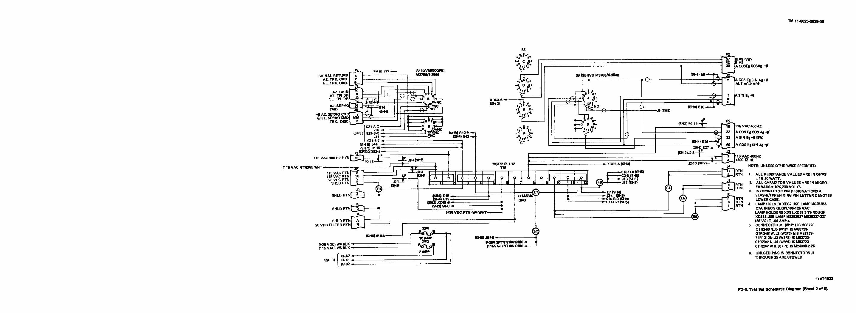


This fine document...
Was brought to you by me:
Liberated Manuals -- free army and government manuals
Why do I do it? I am tired of sleazy CD-ROM sellers, who take publicly available information, slap “watermarks” and other junk on it, and sell it. Those masters of search engine manipulation make sure that their sites that sell free information, come up first in search engines. They did not create it... They did not even scan it... Why should they get your money? Why are not letting you give those free manuals to your friends?
I am setting this document FREE. This document was made by the US Government and is NOT protected by Copyright. Feel free to share, republish, sell and so on.
I am not asking you for donations, fees or handouts. If you can, please provide a link to liberatedmanuals.com, so that free manuals come up first in search engines:
<A HREF=http://www.liberatedmanuals.com/>Free Military and Government Manuals</A>
– SincerelyIgor Chudovhttp://igor.chudov.com/
– Chicago Machinery Movers