tm 5-4320-258-12 technical manualtm 5-4320-258-12 technical manual operator and organizational...
TRANSCRIPT

TM 5-4320-258-12
TECHNICAL MANUAL
OPERATOR AND ORGANIZATIONAL MAINTENANCE MANUAL
FOR
PUMP, CENTRIFUGAL, POL, GED, 6 IN., 1120 GPM
SKID-MOUNTED (BARNES MODEL US67CCG)
FSN 4320-409-8678
H E A D Q U A R T E R S D E P A R T M E N T O F T H E A R M YAUGUST 1971

WARNING
Before Operation
Do not operate the pump unit in an inclosed area, unless exhaust gases are piped to the outside. Inhalation ofexhaust gases will result in serious illness or death.
Do not smoke or use an open flame in the vicinity when servicing the batteries. Batteries generate hydrogen gas,a highly explosive gas.
When filling the fuel tank always maintain metal to metal contact between the filling apparatus and fuel tank toprevent a spark from being caused by static electricity.
During Operation
Do not fill fuel tank while engine is running.
Do not perform maintenance on pumping unit while it is in operation.
After Operation
Use caution when removing radiator cap while engine is hot. Quick removal will allow coolant to escape and maycause serious injury to personnel.
Use caution when removing cover or cable from batteries, so that batteries do not come in contact with cover.Check for insulation and or space between battery cover and battery terminals.

Changes in Force: C1, C2, C3, C4 and C5 TM 5-4320-258-12C 5
CHANGE HEADQUARTERSDEPARTMENT OF THE ARMY
NO. 5 WASHINGTON, D.C., 10 OCTOBER 1990
Operator and Organizational Maintenance Manual
PUMP, CENTRIFUGAL; POL; GED; 6IN; 1120 GPM;SKID MOUNTED (BARNES MODEL US67CCG)
NSN 4320-00-409-8678
Approved for public release; distribution is unlimited
TM 5-4320-258-12, 24 August 1971, is changed as follows:
Page 2-8, paragraph 2-12, add the following subparagraph:
e. Batteries. Increase battery PMCS frequency. Use distilled water or a good grade of drinking water (excludingmineral water) to bring electrolyte to proper level.
Page 4-1, paragraph 4-2c, add the following note:
NOTEThe 6TN and 6TL batteries can be mixed or matched. However, maintenance-free batteriescannot be mixed or matched with military batteries. The 6TN and or the 6TL batteries willperform properly in hot weather as long as electrolyte levels are carefully monitored. If theelectrolyte expands and causes the level to rise, some fluid must be removed. If the levelbecomes too low due to evaporation, distilled water may be used to obtain the proper level. Agood grade of drinking water (excluding mineral waters) may be used if distilled water is notavailable.
By Order of the Secretary of the Army:
CARL E. VUONOGeneral, United States Army
Chief of StaffOfficial:
THOMAS F. SIKORABrigadier General, United States Army
The Adjutant General
DISTRIBUTION:
To be distributed in accordance with DA Form 12-25E, (qty rqr block no. 1333).
U.S. GOVERNMENT PRINTING OFFICE: 1991 554-123/20121
1/(2 Blank)
Change in force: C1, C2, C3, and C4 TM 5-4320-258-12C 4
THIS PUBLICATION IS A COURTESY QUICK COPY FROMCHANGE THE UNITED STATES ARMY PUBLICATIONSDISTRIBUTION, HEADQUARTERS
CENTER ST. LOUIS, MISSOURI, TO MEET YOUR NEEDS DEPARTMENT OF THE ARMYNO. 4. WHILE WE REPLENISH OUR REGULAR STOCK WASHINGTON, D C, 30 October 1977
Operator and Organizational Maintenance ManualPUMP, CENTRIFUGAL; POL: GED:6IN: 1120 GPM:
SKID-MOUNTED (BARNES MODEL US67CCG)NSN 4320-00409-8678
TM 5-4320-258-12, 24 August 1971, is changed as follows:
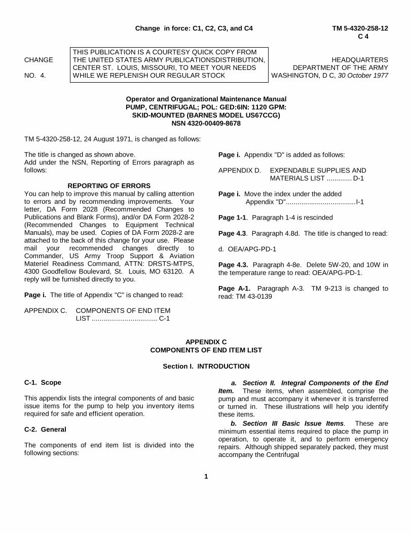
The title is changed as shown above.Add under the NSN, Reporting of Errors paragraph asfollows:
REPORTING OF ERRORSYou can help to improve this manual by calling attentionto errors and by recommending improvements. Yourletter, DA Form 2028 (Recommended Changes toPublications and Blank Forms), and/or DA Form 2028-2(Recommended Changes to Equipment TechnicalManuals), may be used. Copies of DA Form 2028-2 areattached to the back of this change for your use. Pleasemail your recommended changes directly toCommander, US Army Troop Support & AviationMateriel Readiness Command, ATTN: DRSTS-MTPS,4300 Goodfellow Boulevard, St. Louis, MO 63120. Areply will be furnished directly to you.
Page i. The title of Appendix "C" is changed to read:
APPENDIX C. COMPONENTS OF END ITEMLIST .................................. C-1
Page i. Appendix "D" is added as follows:
APPENDIX D. EXPENDABLE SUPPLIES ANDMATERIALS LIST ............. D-1
Page i. Move the index under the addedAppendix "D"....................................I-1
Page 1-1. Paragraph 1-4 is rescinded
Page 4.3. Paragraph 4.8d. The title is changed to read:
d. OEA/APG-PD-1
Page 4.3. Paragraph 4-8e. Delete 5W-20, and 10W inthe temperature range to read: OEA/APG-PD-1.
Page A-1. Paragraph A-3. TM 9-213 is changed toread: TM 43-0139
APPENDIX CCOMPONENTS OF END ITEM LIST
Section I. INTRODUCTION
C-1. Scope
This appendix lists the integral components of and basicissue items for the pump to help you inventory itemsrequired for safe and efficient operation.
C-2. General
The components of end item list is divided into thefollowing sections:
a. Section II. Integral Components of the EndItem. These items, when assembled, comprise thepump and must accompany it whenever it is transferredor turned in. These illustrations will help you identifythese items.
b. Section III Basic Issue Items. These areminimum essential items required to place the pump inoperation, to operate it, and to perform emergencyrepairs. Although shipped separately packed, they mustaccompany the Centrifugal
1

TM 5-4320-258-12C 4
pump during operation and whenever it is transferred between accountable officers. The illustrations will assist you withhard-to-identify items. This manual is your authority to requisition replacement BII, based on Table(s) of Organization andEquipment (TOE)/Modification Table of Organization and Equipment (MTOE) authorization of the end item.
C-3. Explanation of Columns
a. Illustration. This column is divided as follows:
(1) Figure Number. Indicates the figure number of the illustration of which the item is shown (if applicable).
(2) Item Number. The number used to identify item called out in the illustration.
b. National Stock Number (NSN). Indicates the National Stock Number assigned to the item in which will be usedfor requisitioning.
c. Part Number (P/N). Indicates the primary number used by the manufacturer, which control the design andcharacteristics of the item by means of its engineering drawings, specifications, standards, and inspection requirementsto identify an item or range of items.
d. Description. Indicates the federal Item name and, if required, a minimum description to identify the item.
e. Location. The physical location of each item listed is given in this column. The lists are designed to inventoryall items in one area of the major item before moving on to an adjacent area.
f. Usable on Code . "USABLE ON" codes are included to help you identify which component items are used on thedifferent models. Identification of the codes used in this list are: Not Applicable.
g. Quantity Required (Qty Req'd). This column lists the quantity of each item required for a complete major item.
h. Quantity. This column is left blank for use during inventory. Under the RCV'D column, list the quantity youactually receive on your major item. The Date columns are for use when you inventory the major item at a later date;such as for shipment to another site.
Section II. INTEGRAL COMPONENTS OF END ITEM
(1) (2) (3) (4) (5) (6) (7) (8)ILLUSTRATION QUANTITY(a) (b) NATIONAL PART NO. USABLE
FIGURE FIGURE STOCK & DESCRIPTION LOCATION ON QTYNO. NO. NO. FSCM CODE REQD RCVD DATE DATE
4 16 6140-00-057- MS35000-3 Battery. 22554 (96906) Storage
24 1 4330.01.036- F162P03111 Crank, Start- 19263 (14351) ing, Hand
2

TM 5-4320-258-12C 4
Section III. BASIC ISSUE ITEMS
(1) (2) (3) (4) (5) (6) (7) (8)ILLUSTRATION QUANTITY(a) (b) NATIONAL PART NO. USABLE
FIGURE FIGURE STOCK & DESCRIPTION LOCATION ON QTYNO. NO. NO. FSCM CODE REQD RCVD DATE DATE
5120-00-900-6103 Hammer, Hand 1
5120-00-449-8083 Wrench, Open End 1AdjustableTM 5-4320-258-12Operator andOrganizationalMaintenance Manualpump. Centrifugal;POL; GED; 6-gin; 1120GPM; skid mounted(Barnes Model US-67CCG) NSN 4320-00-409-86781
LO 5-4320-258-12Pump. centrifugal POL,GED, 6 In. 1120 GPM;skid mounted (BarnesModel US67CCG) w/En-gine Continental ModelFS 244-06097P1
APPENDIX DEXPENDABLE SUPPLIES AND MATERIALS LIST
Section I. INTRODUCTION
D-1. Scope
This appendix lists expendable supplies and materialsyou will need to maintain and operate the pump. Theseitems are authorized to you by CTA50-970, ExpendableItems (except Medical, Clam V, Repair Parts. andHeraldic Items).
D-2. Explanation of Columns
a. Column 1 - Item Number. This number isassigned to the entry of the listing and is referenced inthe narrative instructions to identify the material (e.g.,"Use cleaning compound, Item 5, App. D").
b. Column 2 - Level. This column identifies thelowest level of maintenance that requires the listed item.
c. Column 3 - National Stock Number. This isthe National Stock Number assigned to the item; use itto request or requisition the item.
d. Column 4 - Description. Indicates the federalitem name and, if required, a description to identify theitem. The last line for each item indicates the partnumber followed by the Federal Supply Code forManufacturer (FSCM) in parenthesis, if applicable.
e. Column 5 - Unit of Measure (U/M). Indicatesthe measure used in performing the actual maintenancefunctions. This measure is expressed by a two-character alphabetic abbreviation, (e.g., ea, in, pr). Ifthe unit of measure differs from the unit of issue,requisition your lowest unit of issue that will satisfy yourrequirements.
3
TM 5-4320-258-12C 4
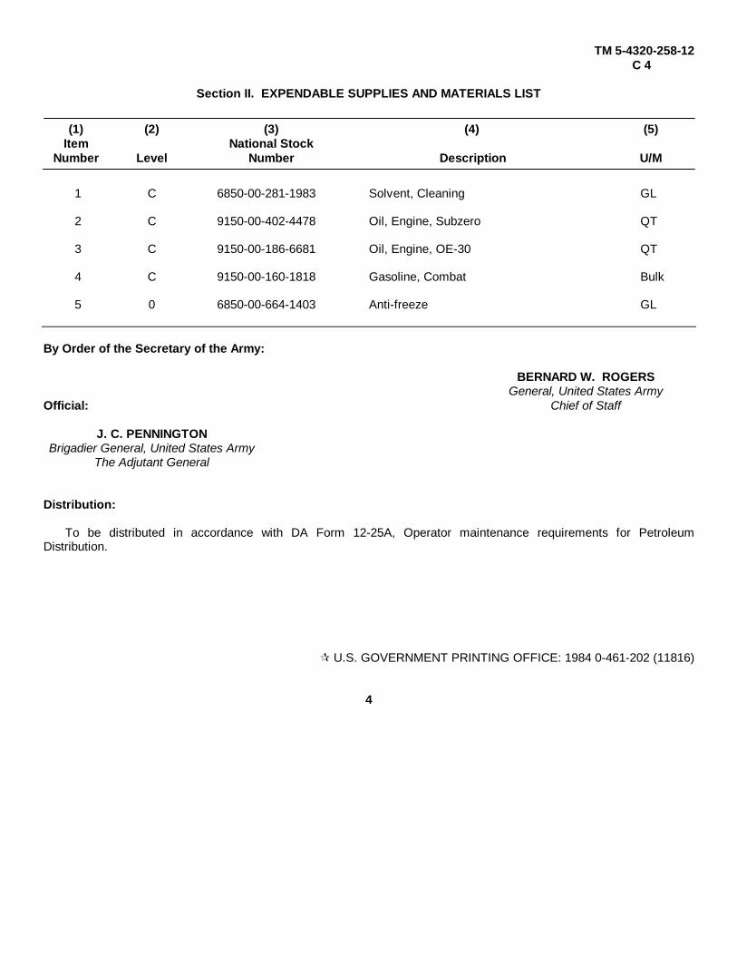
Section II. EXPENDABLE SUPPLIES AND MATERIALS LIST
(1) (2) (3) (4) (5)Item National Stock
Number Level Number Description U/M
1 C 6850-00-281-1983 Solvent, Cleaning GL
2 C 9150-00-402-4478 Oil, Engine, Subzero QT
3 C 9150-00-186-6681 Oil, Engine, OE-30 QT
4 C 9150-00-160-1818 Gasoline, Combat Bulk
5 0 6850-00-664-1403 Anti-freeze GL
By Order of the Secretary of the Army:
BERNARD W. ROGERSGeneral, United States Army
Official: Chief of Staff
J. C. PENNINGTONBrigadier General, United States Army
The Adjutant General
Distribution:
To be distributed in accordance with DA Form 12-25A, Operator maintenance requirements for PetroleumDistribution.
U.S. GOVERNMENT PRINTING OFFICE: 1984 0-461-202 (11816)
4

Changes in Force: C1, C2, and C3 TM 5-4320-258-12C 3
CHANGE HEADQUARTERSDEPARTMENT OF THE ARMY
No. 3 WASHINGTON. DC, 20 May 1974
Operator and Organizational Maintenance ManualPUMP, CENTRIFUGAL; POL; GED; 6-IN: 1120 GPM; SKIDMOUNTED
(BARNES MODEL US67CCG) FSN 4320-409-8678
TM 5-4320-25812, 24 August 1971, is changed as follows:Inside cover. Add the following warnings:
WARNING
Operation of this equipment presents a noise hazard to personnel in the area. The noise levelexceeds the allowable limits for unprotected personnel. Wear ear muffs or ear plugs which werefitted by a trained professional.
WARNING
Dry cleaning solvent, P-D-680, used to clean parts is potentially dangerous to personnel andproperty. Do not use near open flame or excessive heat. Flash point of solvent is 100° - 138°F.
By Order of the Secretary of the Army:
CREIGHTON W. ABRAMSGeneral, United States Army
Official: Chief of StaffVERNE L. BOWERS
Major General, United States ArmyThe Adjutant General
Distribution:
To be distributed in accordance with DA Form 12-25A (qty rqr block No. 153) Operator's Maintenance requirementsfor Petroleum Distribution.
THIS PUBLICATION IS A COURTESY QUICK COPY FROM THEUNITED STATES ARMY PUBLICATIONS DISTRIBUTION CENTER,ST. LOUIS, MISSOURI, TO MEET YOUR NEEDS WHILE WEREPLENISH OUR REGULAR STOCK.
GPO 806-865
1
Changes in force: C 1 and C 2 TM 5-4320-258-12C 2
Change HEADQUARTERSDEPARTMENT OF THE ARMY
No. 2 Washington, D.C., 7 February 1974
Operator and Organizational Maintenance Manual
PUMP, CENTRIFUGAL; POL; GED; 6-IN; 1120 GPM;
SKID-MOUNTED (BARNES MODEL US67CCG) FSN 4320-409-8678
TM 5-4320-258-12, 24 August 1971, is changed as follows:
Page 4-17. Paragraph 4-25b(2) is superseded as follows:(2) Remove the governor, items 26 and 32 thru 37, figure 4-11.
Paragraph 4-25d(1) is superseded as follows:(1) Remove magneto (para 4-34a) before installing governor. Install governor by reversing removal procedure
(para 4-250(2). After installing governor, install magneto (para 4-34J).
}

By Order of the Secretary of the Army:
CREIGHTON W. ABRAMSGeneral, United States Army
Official: Chief of Staff
VERNE L. BOWERSMajor General, United States Army
The Adjutant General
Distribution:
To be distributed in accordance with DA Form 12-25A (qty rqr block no. 153), Operator requirements for PetroleumDistribution.
U.S. GOVERNMENT PRINTING OFFICE: 1974-768114/1024

TM 5-4320-258-12C1
Change HEADQUARTERSDEPARTMENT OF THE ARMY
No. 1 Washington, DC, 10 October 1973
Operator and Organizational Maintenance ManualPUMP, CENTRIFUGAL; POL; GED; 6-IN; 1120 GPM;
SKID-MOUNTED (BARNES MODEL US67CCG) FSN 4320-409-8678
TM 5-4320-258-12, 24 August 1971, is changed asfollows:
Warning Page, add to During Operation: the following:
NOISE HAZARDS exist within twelve (12) feet ofpump when operating. Ear protection required whenpersonnel are exposed to noise more than four (4) hoursduring one (1) day.Page 1-1. Paragraph 1-4, the mailing address ischanged to read:
Commander, US Army Troop Support Command,ATTN: AMSTS-MP, 4300 Goodfellow Blvd, St. Louis,MO 63120.Page 2-1. Add to paragraph 2-2a the followingsentence.
Caution signs that are legible from a distance oftwelve (12) feet will be posted in the operating area.Signs will read "CAUTION, NOISE HAZARD AREA -Hearing protection required within twelve (12) feet whenpump is operating".Page 2-6. Add to paragraph 2-7a the following warning.
WARNINGNOISE HAZARDS exist within twelve(12) feet of pump when operating.Ear protection required whenpersonnel are exposed to noise morethan four (4) hours during one (1)day. Aural protectors, FSNs 4240-691-5617,4240-762-2582or4240-991-1910 should be worn.
By order of the Secretary of the Army:
CREIGHTON W. ABRAMSGeneral, United States Army
Chief of StaffOfficial:
VERNE L. BOWERSMajor General, United States Army
The Adjutant General
Distribution:
To be distributed in accordance with DA Form 12-25A (qty rqr block No. 153), Operator requirements for PetroleumDistribution.
U.S. GOVERNMENT PRINTING OFFICE: 1973-768110/528
1
}

TM 5-4320-258-12
TECHNICAL MANUALHEADQUARTERSDEPARTMENT OF THE ARMY
No. 5-4320-258-12 WASHINGTON, D.C., 24 August 1971
OPERATOR AND ORGANIZATIONAL MAINTENANCE MANUALPUMP, CENTRIFUGAL, POL, GED, 6 IN., 1120 GPM,
SKID-MOUNTED, (BARNES MODEL US67CCG)
FSN 4320-409-8678
Paragraphs PagesCHAPTER 1. INTRODUCTION
Section I. General ..............................................................................................1-1 - 1-4 1-1II. Description and data ..........................................................................1-5 - 1-7 1-1
CHAPTER 2. OPERATING INSTRUCTIONSSection I. Service upon receipt of materiel ........................................................2-1 - 2-2 2-1
II. Movement to a new worksite ..............................................................2-3 - 2-4 2-2III. Controls and instruments ...................................................................2-5 - 2-6 2-2IV. Operation under usual conditions ........................................................2-7 - 2-10 2-6V. Operation under unusual conditions ....................................................2-11 - 2-18 2-8
CHAPTER 3. OPERATOR'S MAINTENANCE INSTRUCTIONSSection I. Basic issue items ................................................................................3-1 3-1
II. Lubrication instructions ......................................................................3-2 3-1III. Preventive maintenance checks and services.....................................3-3 - 3-4 3-1IV. Troubleshooting - ................................................................................3-5 - 3-6 3-2
CHAPTER 4. ORGANIZATIONAL MAINTENANCE INSTRUCTIONSSection I. Service upon receipt of equipment......................................................4-1 - 42 4-1
II. Destruction of materiel to prevent enemy use .....................................4-3 - 4-4 4-2III. Repair parts, special tools, and equipment..........................................4-5 - 4-7 4-2IV. Lubrication instructions ......................................................................4-8 - 4-10 4-2V. Preventive maintenance checks and services.....................................4-11 - 4-12 4-4
VI. Troubleshooting .................................................................................4-13 - 4-14 4-5VII. Radio interference suppression ..........................................................4-15 - 4-16 4-7
VIII. Maintenance of air cleaner, exhaust system, and engine housing .......4-17 - 4-20 4-7IX. Maintenance of fuel system ................................................................4-21 - 4-26 4-12X. Maintenance of cooling system ...........................................................4-27 - 4-31 4-19
XI. Maintenance of ignition system...........................................................4-32 - 4-34 4-23XII. Maintenance of electrical system ........................................................4-36 - 4-41 4-29
XIII. Maintenance of controls and instruments ...........................................4-42 - 4-45 4-39XIV. Maintenance of pump and coupling ....................................................4-46 - 4-48 4-43XV. Engine testing ....................................................................................4-49 - 4-51 4-45
APPENDIX A. REFERENCES ................................................................................................................ A-1
APPENDIX B. MAINTENANCE ALLOCATION CHART .......................................................................... B-1
APPENDIX C. BASIC ISSUE ITEMS LIST AND REPAIR PARTS AND SPECIALTOOLS LIST -................................................................................................................... C-1
INDEX.............................................................................................................................................................I-1
i
}

LIST OF ILLUSTRATIONS
Number Title Page
1-1 Centrifugal pump, left front view ...................................................................................................1-21-2 Centrifugal pump, right rear view .................................................................................................1-31-3 Engine wiring diagram...................................................................................................................1-42-1 Left side of engine, showing drain plugs and charging receptacle..................................................2-22-2 Control panel controls and instruments..........................................................................................2-32-3 Miscellaneous controls, indicators, and plugs ................................................................................2-42-4 Fuel tank and related parts ...........................................................................................................2-52-5 Engine starting instructions ...........................................................................................................2-62-6 Stopping instructions .....................................................................................................................2-74-1 Battery box with batteries installed ...............................................................................................4-14-2 Tachometer drive and engine overspeed governor, showing lubrication points..............................4-34-3 Engine-to-pump connections ........................................................................................................4-44-4 Air cleaner, exploded view ............................................................................................................4-84-5 Air cleaner and piping, exploded view ..........................................................................................4-94-6 Muffler and piping, exploded view ................................................................................................4-104-7 Engine housing, exploded view ....................................................................................................4-114-8 Left side of engine, identifying components...................................................................................4-124-9 Fuel strainer, exploded view..........................................................................................................4-134-10 Fuel lines and fittings, exploded view ...........................................................................................4-134-11 Fuel system components, exploded view .....................................................................................4-144-12 Carburetor and related parts .........................................................................................................4-164-13 Magneto and governor installation ................................................................................................4-174-14 Primer pump, lines, and fittings, exploded view.............................................................................4-184-15 Reverse-flushing the radiator ........................................................................................................4-194-16 Reverse-flushing the engine block.................................................................................................4-204-17 Thermostat, outlet elbow, coolant and oil cooler lines and fittings, exploded view..........................4-214-18 Alternator mounting.......................................................................................................................4-224-19 Water pump and cooling fan, exploded view ................................................................................4-224-20 Radiator and related parts, exploded view ....................................................................................4-234-21 Ignition system, exploded view -....................................................................................................4-254-22 Magnetto-spark plug connections .................................................................................................4-264-23 Magneto, exploded view ...............................................................................................................4-274-24 Timing marks on distributor gear and rotor shaft , ........................................................................4-284-26 Distributor gear properly alined with rotor shaft gear......................................................................4-284-26 Right side of engine, showing components....................................................................................4-304-27 Electrical system setup for battery voltage and isolation diode test................................................4-314-28 Field current draw test setup .........................................................................................................4-324-29 Voltage regulator operating voltage test setup...............................................................................4-334-30 Alternator output and system test setup ........................................................................................4-344-31 Battery charging system, exploded view .......................................................................................4-354-32 Alternator brush assembly, exploded view ....................................................................................4-364-33 Alternator brush assembly, showing continuity paths .....................................................................4-364-34 Engine starter brushes, exploded view .........................................................................................4-384-35 Engine starter test setup................................................................................................................4-384-36 Control panel engine controls and instruments, exploded view .....................................................4-404-37 Tachometer and drive, exploded view...........................................................................................4-414-38 Suction and discharge gages, lines, and fittings, exploded view ...................................................4-424-39 Centrifugal pump, removal and installation ...................................................................................4-434-40 Pump coupling, exploded view .....................................................................................................4-44
ii

CHAPTER 1
INTRODUCTION
Section I. GENERAL
1-1. Scope
These instructions are published for use by personnel towhom the Barnes Manufacturing Company ModelUS67CCG Centrifugal Pump is issued. They provideinformation on the operation and organizationalmaintenance of the equipment as allocated by theMaintenance Allocation Chart.
1-2. Forms and Records
Maintenance forms, records, and reports which are usedby maintenance personnel at all maintenance levels arelisted in and prescribed by TM 38-750.
1-3. Administrative Storage
Preparation, care, and removal of equipment inadministrative storage will be in accordance with theapplicable requirements of TM 740-90-1 (AdministrativeStorage of Equipment).
1-4. Reporting of Errors
Report of errors, omissions, and recommendations forimproving this publication by the individual user isencouraged. Reports should be submitted on DA Form2028, Recommended Changed to Publications, andforwarded directly to Commanding General, U.S. ArmyMobility Equipment Command, ATTN: AMSME-MP,4300 Goodfellow Boulevard, St. Louis, Mo. 63120.
Section II. DESCRIPTION AND DATA
1-5. Description
a. Centrifugal Pump Model US67CCG (figs. 1-1and 1-2) consists primarily of a gasoline engine and acentrifugal pump mounted on a welded skid base. Thetorque from the engine is transferred to the pumpthrough a flexible coupling.
b. The centrifugal pump has a 6-inch suctionnipple and a 6-inch discharge elbow. The nipple andelbow are grooved to receive a hose. The pump iscapable of pumping 1120 GPM at governed speed of2450 RPM, with a total dynamic head of 100 feet. It isself priming and has an integral check valve whichretains the fluid in the pump body after shut down.
c. The gasoline engine is a 6-cylinder, liquid-cooled, pressure-lubricated, L-head, 4-stroke-cycle unit.It is completely housed in a sheet-metal housing.Engine drains are piped to the outside of the enginehousing to provide easy access for servicing.
1-6. Differences in Models
This technical manual covers only Centrifugal PumpModel US67CCG manufactured by Barnes
Manufacturing Company, Mansfield, Ohio. No knowndifferences exist on the pumps procured under thismodel number.
1-7. Identification and Tabulated Data
a. Identification. The centrifugal pump has threeidentification plates.
(1) US data plate. The US data plate is locatedon front of the pump above the suction flange. Itindicates the pump identification number, serial number,dimensions, weight, and shipping information.
(2) Engine plate. The engine data plate islocated on alternator side of the engine block. Itindicates engine identification numbers, serial number,valve tappet clearance information, and patentinformation.
(3) Instruction plate. The pump instruction plateis located in the cover of the control panel. It identifiesthe controls and provides basic operating instructions.
1-1
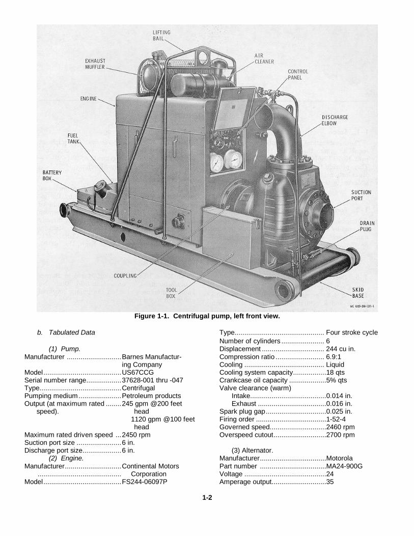
Figure 1-1. Centrifugal pump, left front view.
b. Tabulated Data Type.............................................. Four stroke cycleNumber of cylinders ...................... 6
(1) Pump. Displacement ................................ 244 cu in.Manufacturer ............................Barnes Manufactur- Compression ratio ......................... 6.9:1
ing Company Cooling ......................................... LiquidModel........................................US67CCG Cooling system capacity.................18 qtsSerial number range..................37628-001 thru -047 Crankcase oil capacity ...................5% qtsType..........................................Centrifugal Valve clearance (warm)Pumping medium......................Petroleum products Intake.......................................0.014 in.Output (at maximum rated ........245 gpm @200 feet Exhaust ...................................0.016 in.
speed). head Spark plug gap...............................0.025 in.1120 gpm @100 feet Firing order ....................................1-52-4head Governed speed.............................2460 rpm
Maximum rated driven speed ...2450 rpm Overspeed cutout...........................2700 rpmSuction port size .......................6 in.Discharge port size....................6 in. (3) Alternator.
(2) Engine. Manufacturer..................................MotorolaManufacturer.............................Continental Motors Part number ..................................MA24-900G
........................................... Corporation Voltage ..........................................24Model........................................FS244-06097P Amperage output............................35
1-2
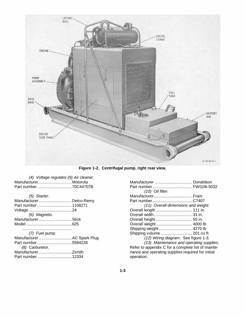
Figure 1-2. Centrifugal pump, right rear view.
(4) Voltage regulator.(9) Air cleaner.Manufacturer.............................Motorola Manufacturer ................................ DonaldsonPart number ..............................70C44707B Part number .................................. FWG06-5032
(10) Oil filter.(5) Starter. Manufacturer................................. Fram
Manufacturer.............................Delco-Remy Part number .................................. C7407Part number ..............................1108271 (11) Overall dimensions and weight.Voltage .....................................24 Overall length ............................... 111 in.
(6) Magneto. Overall width................................. 31 in.Manufacturer.............................Slick Overall height ............................... 55 in.Model........................................625 Overall weight ............................... 4000 lb
........................................... Shipping weight............................. 4270 lb(7) Fuel pump. Shipping volume ........................... 201 cu ft
Manufacturer.............................AC Spark Plug (12) Wiring diagram. See figure 1-3.Part number ..............................5594228 (13) Maintenance and operating supplies.
(8) Carburetor. Refer to appendix C for a complete list of mainte-Manufacturer.............................Zenith nance and operating supplies required for initialPart number . ............................12334 operation.
1-3

Figure 1-3. Engine wiring diagram.
1-4

CHAPTER 2
OPERATING INSTRUCTIONS
Section I. SERVICE UPON RECEIPT OF MATERIEL
2-1. Inspecting and Servicing the Equipment
a. Inspect the unpacked pump assembly asfollows:
(1) Inspect for cracks, dents, and otherdamage that may have occurred during shipment.
(2) Inspect for loose or missing hardware.(3) Check the engine for leaking.(4) Inspect the suction and discharge ports of
pump for damaged ends and burred grooves.(5) Using the engine crank (fig. 1-2), turn
over the engine with the battery disconnect switch andignition switch in the OFF positions. The engine andpump shall turn freely without binding or scraping orother signs of faulty operation. Be careful that the crankdoes not drop onto the fuel gage on the fuel tank.
(6) Inspect the control panel (fig. 1-1) fordamaged controls and instruments.
(7) Remove the engine side panels (fig. 1-2).Inspect all hoses for abrasions, cracks, fraying, andother damage.
(8) Tighten all loose hardware. Report anyother damage to the required authority.
b. Servicing.(1) Refer servicing of the equipment to
organizational maintenance.(2) Perform all daily preventive maintenance
services indicated in table 3-1.
2-2. Installation
Install the centrifugal pump as follows:
a. Locate the pump assembly on a solid, flatsurface as close as possible to the source of liquidsupply. Allow ample room around the pump to supportthe suction and discharge hoses and to service thepump as required.
Caution: The tilt of the pump when spotted foroperation shall not exceed 15 degrees fromhorizontal. An angle of more than 15 degrees will
result in inefficient operation of the enginelubrication system and may cause severe damage tothe engine or automatic shutoff due to low oilpressure.
b. Connect the suction line to the suction port (fig.1-1), as follows:
(1) The suction port is provided with a 6-inchgrooved nipple. Connect to mating grooved pipe withlock ring.
(2) Keep the suction line as short as possibleand the suction lift as low as possible. Reduction inpumping capacity becomes noticeable at suction lifts inexcess of 15 feet and is very pronounced at 25 feet. Donot operate the pump with a suction lift in excess of 25feet.
(3) The suction line should be as large adiameter and as short as practical, and should beinstalled with as few bends as possible. Use no fittingsof less than a 6-inch diameter.
(4) The highest point in the suction lineshould be at the pump, and the line should be laid in adecline from the pump to the source. Avoid high pointswhich will form air pockets.
(5) Make sure that connections in the suctionline are air tight. Even a small leak will greatly reducepumping efficiency and may cause difficulty in priming,especially when operating with a high suction lift.
(6) Support the suction line at or near thepump to prevent strain.
c. Install the discharge line on the discharge elbow(fig. 1-1), as follows:
(1) The discharge elbow is provided with a 6-inch grooved pipe. Connect to mating grooved pipe withlock ring.
(2) Avoid unnecessary fittings in thedischarge line. When necessary to use elbows, uselong radius type to reduce friction loss.
2-1
(3) Support the discharge line at or near thepump to prevent strain.
Warning: Do not operate the pump unit in anenclosed area unless exhaust gases are piped to theoutside. Inhalation of exhaust fumes will result inserious illness or death.
d. If the centrifugal pump is operated indoors,provide piping to carry exhaust gases to the outside of
the building. Make sure that the diameter of the exhaustpiping is large enough to prevent excessive backpressure in the engine.
e. If an auxiliary fuel supply is to be used, connecta fuel line between the source of supply and the 3-wayfuel source selector valve (1, fig. 2-4) on the fuel tank.Operate the fuel valve to the AUX position.
Section II. MOVEMENT TO A NEW WORKSITE
2-3. Dismantling for Movement
Dismantle the pump for movement to a new worksite asfollows:
a. Disconnect the suction line and discharge linefrom the pump. If possible, drain the dis-
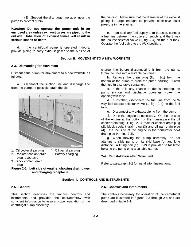
1. Oil cooler drain plug 4. Oil pan drain plug2. Radiator coolant drain 5. Battery charging
plug receptacle3. Block coolant drain
plugFigure 2-1. Left side of engine, showing drain plugs
and charging receptacle.
charge line before disconnecting it from the pump.Drain the lines into a suitable container.
b. Remove the drain plug (fig. 1-1) from thebottom of the pump to drain the pump housing. Catchthe fluid in a suitable container.
c. If there is any chance of debris entering thepump suction and discharge openings, cover theopeningwith tape.
d. If installed, disconnect the fuel line from the 3-way fuel source selector valve (1, fig. 2-4) on the fueltank.
e. Disconnect any exhaust piping from the pump.f. Drain the engine as necessary. On the left side
of the engine at the bottom of the housing are the oilcooler drain plug (1, fig. 2-1), radiator coolant drain plug(2), block coolant drain plug (3) and oil pan drain plug(4). On the side of the engine is the carburetor bowldrain plug (4, fig. 2-3).
g. When moving the pump assembly, do notattempt to slide pump on its skid base for any longdistance. A lifting bail (fig. 1-2) is provided to facilitatehoisting the pump onto a suitable carrier.
2-4. Reinstallation after Movement
Refer to paragraph 2-2 for installation instructions.
Section Ill. CONTROLS AND INSTRUMENTS
2-5. General
This section describes the various controls andinstruments and provides the operator/crew withsufficient information to assure proper operation of thecentrifugal pump assembly.
2-6. Controls and Instruments
The controls necessary for operation of the centrifugalpump are illustrated in figures 2-2 through 2-4 and aredescribed in table 2-1.
2-2
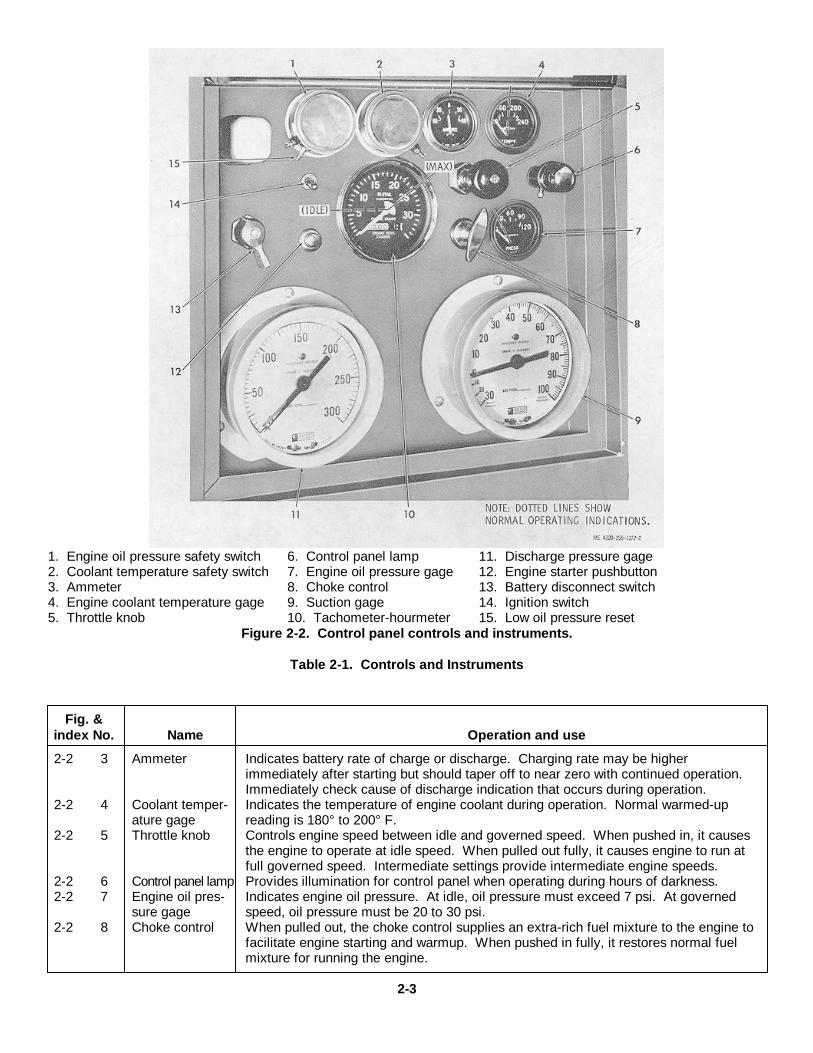
1. Engine oil pressure safety switch 6. Control panel lamp 11. Discharge pressure gage2. Coolant temperature safety switch 7. Engine oil pressure gage 12. Engine starter pushbutton3. Ammeter 8. Choke control 13. Battery disconnect switch4. Engine coolant temperature gage 9. Suction gage 14. Ignition switch5. Throttle knob 10. Tachometer-hourmeter 15. Low oil pressure reset
Figure 2-2. Control panel controls and instruments.
Table 2-1. Controls and Instruments
Fig. &index No. Name Operation and use
2-2 3 Ammeter Indicates battery rate of charge or discharge. Charging rate may be higher immediately after starting but should taper off to near zero with continued operation. Immediately check cause of discharge indication that occurs during operation.
2-2 4 Coolant temper- Indicates the temperature of engine coolant during operation. Normal warmed-upature gage reading is 180° to 200° F.
2-2 5 Throttle knob Controls engine speed between idle and governed speed. When pushed in, it causes the engine to operate at idle speed. When pulled out fully, it causes engine to run at full governed speed. Intermediate settings provide intermediate engine speeds.
2-2 6 Control panel lamp Provides illumination for control panel when operating during hours of darkness.2-2 7 Engine oil pres- Indicates engine oil pressure. At idle, oil pressure must exceed 7 psi. At governed
sure gage speed, oil pressure must be 20 to 30 psi.2-2 8 Choke control When pulled out, the choke control supplies an extra-rich fuel mixture to the engine to
facilitate engine starting and warmup. When pushed in fully, it restores normal fuel mixture for running the engine.
2-3

1. Air eliminator valve 4. Carburetor drain plug 7. Suction gage valve2. Air cleaner restriction indicator 5. Dummy plug 8. Discharge pressure gage valve8. Engine primer pump 6. Fill plug
Figure 2-3. Miscellaneous controls, indicators, and plugs.
2-4

Table 2-1-Continued
Fig. &index No. Name Operation and use
2-2 9 Suction gage Compound gage indicates either vacuum or pressure condition at suction port when suction gage valve is open. Indication depends upon specific operating conditions.
2-2 10 Tachometer- Indicates the engine speed in hundreds of rpms. Normal governed speed ratinghourmeter is 2450 rpm. Engine speed at full load should not go beyond this level. Hour-meter
indicates engine running time based on operating speed (engine revolutions x 100, 000).
2-2 11 Discharge pres- Indicates pump discharge pressure when discharge pressure gage valve is open.sure gage High pressure indicates high discharge head or discharge line restriction. Normal
discharge pressure varies with operating conditions.2-2 12 Starter push- When the battery disconnect switch and ignition switch are ON, the starter button
pushbutton, when pressed, energizes the engine starter to turn over the engine for starting. Safety bypass switch (15) must be held closed during starting to bypass oil pressure safety switch.
2-2 13 Battery discon- In the ON position, it closes circuits to the starting system and ignition switch.nect switch In the OFF position, it interrupts these circuits.
2-2 14 Ignition switch In the ON position, it energizes the oil pressure and water temperature gage circuits andremoves the ground from the ignition circuit to permit engine ignition. Battery disconnect switch must be in ON position to make this switch operative. When moved to OFF, ignition switch stops the engine by grounding the magneto, regardless of the position of battery disconnect switch.
2-2 15 Low oil pressure When pressed, it resets the low oil pressure safety circuit to allow engine starting.reset
2-3 1 Air eliminator When open, the air eliminator valve releases air in the discharge piping. Normallyvalve closed during operation after starting.
2-3 2 Air cleaner re- Indicates red when air cleaner is clogged, preventing free air passage. Requiresstriction reset after air cleaner service.indicator
2-3 3 Engine primer When operated, it pumps raw fuel into the intake manifold to facilitate starting.pump
2-3 7 Suction gage When open, the suction gage valve applies suction port pressure to suction gage.valve
2-3 8 Discharge pres- When open, the discharge pressure gage valve applies discharge pressure to dischargesure gage valve pressure gage.
2-4 1 3-way fuel source This valve has three positions as follows:selector valve OFF position shuts off fuel supply to engine.
TANK position opens tank-to-engine fuel supply line.AUX position opens the line between the auxiliary fuel supply and engine.
2-4 2 Fuel tank gage Indicates level of fuel in fuel tank
1. Fuel source selector 3. Fuel tank filler capvalve 4. Autofill connector
2. Fuel tank level gage 5. Auxiliary fuel lineconnector
Figure 2-4. Fuel tank and related parts.
2-5

Section IV. OPERATION UNDER USUAL CONDITIONS
2-7. General
a. The instructions in this section are for theinformation and guidance of personnel responsible foroperation of the centrifugal pump.
b. The operator must know how to perform everyoperation of which the centrifugal pump is capable. This
section contains instructions on starting and stopping thecentrifugal pump, on operation of the centrifugal pump,and on coordinating the basic motions to perform thespecific tasks for which the equipment is designed.Since nearly every job presents a different problem, theoperator may have to vary given procedures to fit theindividual job.
STEP 1. PLACE FUEL SOURCE SELECTOR VALVE TO TANK OR AUXILIARY, WHICHEVER IS APPLICABLE.STEP 2. PULL OUT CHOKE CONTROL. PULL OUT THROTTLE KNOB ONE-FOURTH WAY.STEP 3. OPERATE BATTERY DISCONNECT SWITCH TO ON. OPERATE IGNITION SWITCH TO RUN.STEP 4. MOMENTARILY PRESS LOW OIL PRESSURE RESET.STEP 5. PRESS AND HOLD STARTER PUSHBUTTON UNTIL ENGINE STARTS.CAUTION: IF ENGINE FAILS TO START AFTER 30 SECONDS OF CRANKING, RELEASE PUSHBUTTON AND
WAIT 2 MINUTES BEFORE ATTEMPTING AGAIN TO ALLOW STARTER TO COOL. IF ENG INE FAILS TO START AFTER SEVERAL ATTEMPTS, REPORT COND ITION TO ORGAN IZATIONAL MAINTENANCE.
STEP 6. AFTER ENGINE STARTS, RELEASE STARTER PUSHBUTTON AND CHECK THAT OIL PRESSURE GAGE INDICATES NORMAL RANGE.
STEP 7. RUN ENGINE AT ONE-FOURTH THROTTLE UNTIL ENGINE REACHES OPERATING TEMPERATURE. PUSH IN CHOKE IN INCREMENTS TO MAINTAIN SMOOTH ENGINE OPERATIONUNTIL CHOKE CONTROL IS FULLY IN.
Figure 2-5. Engine starting instructions.
2-6

Figure 2-6. Stopping Instructions.
2-8. Startinga. Preparation for Starting.
(1) Perform the necessary daily preventivemaintenance procedures (para 3-4).
(2) If the pump is being started at a newinstallation for the first time or if it has been drainedafter the last period of operation, remove the fill plug (6,fig. 2-3) and fill the body with the liquid to be pumped.
CautionAlways prime the pump beforestarting engine. Operating the pumpdry may damage the seal.
(3) Remove the engine cover panels (fig. 1-2).
b. Starting. Refer to figure 2-5 and start thecentrifugal pump.2-9. Stopping
CautionDo not stop the pump by pulling outthe choke. This floods the cylinderswith raw gasoline, which washesaway the lubricants and makes theengine susceptible to wear.
a. Stop the pump as shown in figure 2-6.b. Perform all after-operation preventive
maintenance services.2-10. Operation Under Usual Conditions
CautionPrime the pump before starting.(para 2-8a)
2-7

a. Start the centrifugal pump (para 2-8).b. Open the suction gage valve (7, fig. 2-3) and
discharge pressure gage valve (8) to operate the gages.Open the air eliminator valve (1) if necessary toeliminate air from discharge system.
c. Pull the throttle knob (5, fig. 2-2) all the way outand operate the pump at maximum governed speed.Depending on pumping conditions, the pump may notstart pumping immediately, since it is necessary for thesuction hose to fill with water. If after a reasonable timethe pump fails to pump, check the suction line carefullyfor leaks. A small air leak will greatly reduce pumpingefficiency under any conditions and especially whenoperating under a high suction lift.
d. After the pump starts pumping, as indicated bya reading on the discharge pressure gage, close the aireliminator valve and adjust the flow from the aireliminator valve and/or a throttle control on the controlpanel to obtain the desired pumping rate or dischargepressure.
e. Check the pump for any unusual or excessivevibration. If excessive vibration is noticed, stop thepump immediately and correct the cause. Vibrationusually results when the pump or connecting lines arenot properly supported, alined or secured.
f. While the pump is in operation, do notcompletely close the valve in the discharge line.Although no serious harm can be done to the pump, therotating impeller churning the water can generateenough heat to cause the liquid in the volute to boil.
Make sure that some passage of liquid continuesthrough the pump during operation.
g. If the rate drops off for no apparent reason,check the suction line for blockage or closed valves.
h. If the engine stops due to an engine overspeedcondition, correct the cause of the overspeed and pressthe reset button (2, fig. 4-2) on the top of the engineoverspeed governor to reset the overspeed circuitbefore attempting to restart the engine.
i. If the engine stops due to a low oil pressurecondition, press the low oil pressure reset (15, fig. 2-2)to reset the oil pressure circuit before attempting torestart.
j. Stop the pump as directed in paragraph 2-9when the pumping cycle is completed.
WarningWhen filling the fuel tank alwaysmaintain metal to metal contactbetween the filling apparatus andfuel tank to prevent a spark frombeing caused by static electricity.
k. During operation, check the fuel level gage (2,fig. 2-4) at intervals and, when necessary, remove thefiller cap (3) and add 91A Gasoline to fill the tank.
l. Check the air cleaner restriction indicator atintervals during operation. If the restriction indicatorshows red, it indicates that the air cleaner requiresservicing after shutdown.
Section V. OPERATION UNDER UNUSUAL CONDITIONS2-11. Operation in Extreme Cold
a. Keep the pump free of ice and snow at all times.Cover it when not in use and, if possible, provide someshelter from the weather.
b. Use a hydrometer to assure that the enginecoolant has sufficient antifreeze to prevent freezing atthe lowest temperature to which the pump will besubjected.
c. Refer to the current lubrication order to assurethat the engine lubricant is the proper grade for thecoldest conditions likely to be encountered.
d. Keep the fuel tank filled when the pump is not inuse. This will prevent moisture from condensing in thefuel system. Moisture in the fuel system can freeze andclog lines, filters, and carburetor jets, preventing fuelfrom reaching the engine.
e. Service the fuel filter frequently to remove anymoisture which may have collected in the fuel bowl.2-12. Operation in Extreme Heat
a. Protect the pump assembly from direct rays ofthe sun if possible.
b. Allow adequate space for ventilation. Use a fanto circulate the air if the pump is operated in anenclosure.
c. Keep the engine and radiator clean to provideproper heat transfer to the air.
d. Check that the lubricants used in the enginecomply with the recommendations of the currentlubrication order.2-13. Operation in High Altitudes
The operating efficiency of both engines andpumps diminishes at higher altitudes. Make sure
2-8

that the engine is operating at peak efficiency to providethe highest possible pump output.2-14. Operation in Sandy or Dusty Areas
a. Maintain a careful check of the air cleanerrestriction indicator. Immediately report toorganizational maintenance when it indicates arestricted condition of the air cleaner. The servicefrequency of air cleaner service must be increased whenoperating under conditions of extreme sand or dust.
b. Take care to prevent sand and dust fromentering the fuel system while filling the fuel tank.Watch the fuel strainer bowl for accumulations of dirt.Report any dirt accumulations in the bowl.2-15. Operation Under Rainy or Humid Conditions
a. Take care to prevent moisture from entering thefuel system. Fill the fuel tank immediately after everyoperating period to prevent moisture in the air fromcondensing and entering the fuel system. Maintain acareful check of the fuel strainer bowl for collections ofmoisture. Report it to organizational maintenance whenmoisture is noted in the fuel bowl.
b. Take special care to prevent rust and corrosionof exposed metal surfaces. Coat exposed metalsurfaces with light grease to prevent rusting. Reportdamaged paint immediately to organizationalmaintenance.2-16. Operation in Salt Water Areas
a. Because of the corrosive action of salt water,use fresh water to wash off any salt water that comes in
contact with the equipment. This will help prevent theformation of rust and corrosion.
b. Coat all unpainted metal surfaces with grease toprevent formation of rust and corrosion.2-17. Operation in Snow
a. Before operation, brush away any snow whichhas seeped into the engine compartment to assure freerotation of the fan and belts and to prevent water fromthe melted snow from entering engine components.
b. Check that the exhaust muffler weathercap hasnot frozen shut as the result of freezing of melting snow.
c. Brush all snow away from the instrument panelto assure clear observation of the instruments.2-18. Operation in Mud
a. Make sure that the pump skid is mounted on afirm base so that it will not become mired in soft earth.Use planking or blocking, if necessary, to prevent thepump from sinking into muddy earth.
b. Keep the radiator free from mud. Mud caked inthe radiator cooling fins will decrease the coolingcapacity of the radiator.
c. Wipe all mud from the instrument panel toprovide clear observation of the instruments.
2-9

CHAPTER 3OPERATOR'S MAINTENANCE INSTRUCTIONS
Section I. BASIC ISSUE ITEMS3-1. Tools, Equipment, and Repair Parts
Tools, equipment, and repair parts authorized for the centrifugal pump are listed in the Basic Issue ItemsList, Appendix C.
Section II. LUBRICATION INSTRUCTIONS3-2. Lubrication Instructions
No lubrication is authorized at the operator/crew maintenance level for this equipment. Refer anytroubles to organizational maintenance.
Section III. PREVENTIVE MAINTENANCE CHECKS AND SERVICES
3-3. GeneralTo insure that the centrifugal pump is ready for
operation at all times, it must be inspectedsystematically so that defects may be discovered andcorrected before they result in serious damage orfailure. The necessary preventive maintenance checksand services to be performed are listed as described inparagraph 3-4. The item numbers indicate thesequence of minimum inspection requirements. Defectsdiscovered during operation of the unit will be noted forfuture correction to be made as soon as operation has
ceased. Stop operation immediately if a deficiency isnoted during operation which would damage theequipment if operation were continued. All deficienciesand shortcomings will be recorded together with thecorrective action taken on DA Form 2404 (EquipmentInspection and Maintenance Worksheet) at the earliestpossible opportunity.3-4. Preventive Maintenance Checks and Services
Refer to table 3-1 for a listing of operator'spreventive maintenance checks and services.
Table 3-1. Preventive Maintenance Checks and Services
Operator Maintenance Category Daily Schedule (or weekly)Interval and sequence No.
Before During After Item to be Procedure Paragraphoperation operation operation inspection reference
1 11 Fuel tank Fill tank if necessary. Check for secure Paragraph 2-10kmounting.
2 Engine and Tighten loose hardware.pumpmounting
3 Battery Check fluid level. If low, report to or- Paragraph 4-2cganizational maintenance.
4 Radiator Check fluid level. If low, report to or- Paragraph 4-2aganizational maintenance.
5 Engine oil Check level with dipstick. If low, report Paragraph 4-2bto organizational maintenance.
3-1
Operator Maintenance Category Daily Schedule (or weekly)Interval and sequence No.
Before During After Item to be Procedure Paragraphoperation operation operation inspection reference
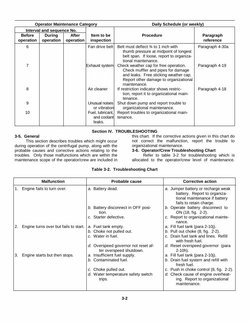
6 Fan drive belt Belt must deflect ¾ to 1 inch with Paragraph 4-30athumb pressure at midpoint of longestbelt span. If loose, report to organiza-tional maintenance.
7 Exhaust system Check weather cap for free operation. Paragraph 4-19Check muffler and pipes for damageand leaks. Free sticking weather cap.Report other damage to organizationalmaintenance.
8 Air cleaner If restriction indicator shows restric- Paragraph 4-18tion, report it to organizational main-tenance.
9 Unusual noises Shut down pump and report trouble toor vibration organizational maintenance.
10 Fuel, lubricant, Report troubles to organizational main-and coolant tenance.leaks.
Section IV. TROUBLESHOOTING3-5. General
This section describes troubles which might occurduring operation of the centrifugal pump, along with theprobable causes and corrective actions relating to thetroubles. Only those malfunctions which are within themaintenance scope of the operator/crew are included in
this chart. If the corrective actions given in this chart donot correct the malfunction, report the trouble toorganizational maintenance.3-6. Operator/Crew Troubleshooting Chart
Refer to table 3-2 for troubleshooting which isallocated to the operator/crew level of maintenance.
Table 3-2. Troubleshooting Chart
Malfunction Probable cause Corrective action
1. Engine fails to turn over. a. Battery dead. a. Jumper battery or recharge weakbattery. Report to organiza-tional maintenance if batteryfails to retain charge.
b. Battery disconnect in OFF posi- b. Operate battery disconnect totion. ON (18, fig. 2-2).
c. Starter defective. c. Report to organizational mainte-nance.
2. Engine turns over but fails to start. a. Fuel tank empty. a. Fill fuel tank (para 2-10j).b. Choke not pulled out. b. Pull out choke (8, fig. 2-2).c. Water in fuel. c. Drain fuel tank and lines. Refill
with fresh fuel.d. Overspeed governor not reset af- d. Reset overspeed governor (para
ter overspeed shutdown. 2-10h).3. Engine starts but then stops. a. Insufficient fuel supply. a. Fill fuel tank (para 2-10j).
b. Contaminated fuel. b. Drain fuel system and refill withfresh fuel.
c. Choke pulled out. c. Push in choke control (8, fig. 2-2).d. Water temperature safety switch d. Check cause of engine overheat-
trips. ing. Report to organizationalmaintenance.
3-2

Malfunction Probable cause Corrective action
e. Oil pressure safety switch trips. e. Check oil level. Report to organi-zational maintenance if low.
f. Engine overspeed governor trips. f. Reset governor (para 2-10h).Start engine and watch tacho-meter to check for overspeed.Report to organizational main-tenance if engine speedexceeds 2600 rpm.
4. Engine runs but unit fails to pump. a. Suction leak. a. Correct leak in auction line.b. Suction lift too high. b. Reduce suction lift to less than 25
feet (para 2-2).c. Pump not primed. c. Prime pump (para 2-8a(2) ).d. Discharge head too high. d. Reduce discharge head.e. Throttle lever not in full-speed e. Operate throttle lever so that en-
position. gine runs at full governedspeed.
5. Engine lacks power. a. Throttle control not in full-speed a. Operate throttle control to provideposition. full speed operation.
b. Air cleaner restricted. b. Check for air cleaner restriction.c. Exhaust weather cap causing ex- c. Free weather cap.
cessive back pressure.
3-3
CHAPTER 4ORGANIZATIONAL MAINTENANCE INSTRUCTIONS
Section I. SERVICE UPON RECEIPT OF EQUIPMENT4-1. General
Inspection of the received equipment is describedin paragraph 2-1. Service the received equipment asdirected in paragraph 4-2 before putting it into operation.4-2. Servicing
a. Check the engine coolant. Make sure theradiator is filled to the required level and that there issufficient antifreeze for the required operating
conditions. Normally, water that is suitable for drinkingis suitable for use in the radiator.
b. Check the oil level in the engine crankcase,using the dipstick (8, fig. 4-26). Add oil if the level isnear the low mark on the dipstick.
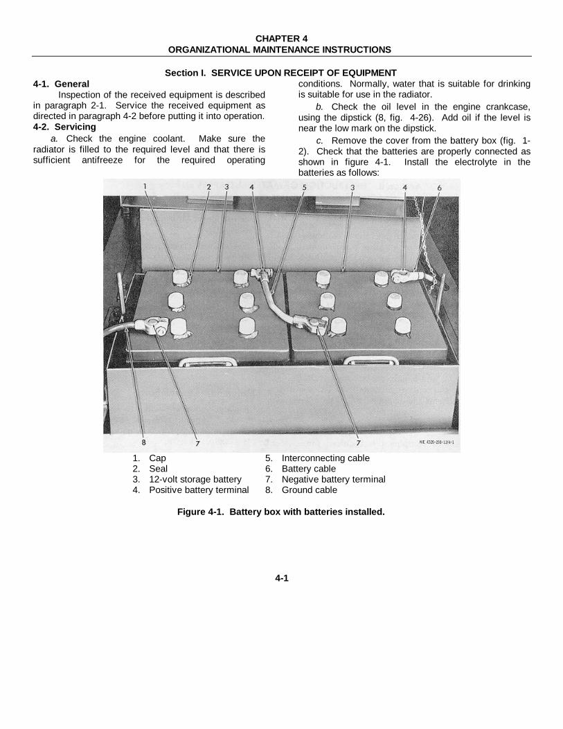
c. Remove the cover from the battery box (fig. 1-2). Check that the batteries are properly connected asshown in figure 4-1. Install the electrolyte in thebatteries as follows:
1. Cap 5. Interconnecting cable2. Seal 6. Battery cable3. 12-volt storage battery 7. Negative battery terminal4. Positive battery terminal 8. Ground cable
Figure 4-1. Battery box with batteries installed.
4-1
(1) Remove the caps and remove anddestroy plastic film used to seal the battery caps.
(2) Fill the batteries to the level indicated withthe separately packed electrolyte. If possible, thebattery and electrolyte should be at 77° F during filling.The battery must be at more than 60° F but not morethan 100° F at filling. Allow the filled batteries to standfor 30 minutes, then check the specific gravity of theelectrolyte. The specific gravity, when temperaturecorrected to 77° F, must be above 1.250.
(3) If the specific gravity of the electrolyte isless than 1.250, or if the battery is not going to be usedwithin 12 hours, or if the battery is going into service at atemperature of less than 0° F, the battery must becharged before use.
WarningDo not smoke or use an open flamein the vicinity when servicing thebatteries. Batteries generatehydrogen gas, a highly explosivegas.
(4) If battery charging is necessary, use aconstant current charger and charge the battery. Checkthe specific gravity of the electrolyte every 30 minutes.
The battery is fully charged when the specific gravityremains constant for three 30-minute intervals.
CautionConstant current battery charging isalways preferred. If a constantpotential charger must be used,battery temperature must bemaintained at less than 130° F byinterrupting the charging procedureas this temperature is approached.
(5) During charging, check the electrolytelevel frequently. Add distilled water when necessary tomaintain the battery electrolyte level. Continue chargingafter adding water to assure proper mixing of thesolution.
(6) After charging, the specific gravity of theelectrolyte must be adjusted to 1.280 +0.010. Thespecific gravity can be lowered, if necessary, byremoving electrolyte and replacing it with distilled water.
(7) After adding electrolyte, charge thebatteries a minimum of once each month when thebatteries are not in service.
(8) Batteries can be charged withoutremoving the batteries from the equipment. Use thebattery charging receptacle (5, fig. 2-1).
Section II. DESTRUCTION OF MATERIEL TO PREVENT ENEMY USE
4-3. GeneralOrganizational maintenance personnel
responsible for the maintenance of the centrifugal pumpmust have a thorough knowledge of the proceduresnecessary to destroy this equipment in the event ofabandonment or imminent capture by the enemy.Destruction procedures shall be carried out only on theexpressed orders of the responsible unit commander.
4-4. Destruction of Materiel to Prevent Enemy UseFor instructions regarding destruction of
equipment to prevent enemy use, refer to TM 750-244-3(Procedures for Destruction of Equipment to PreventEnemy Use) (Mobility Equipment Command).
Section III. REPAIR PARTS, SPECIAL TOOLS, AND EQUIPMENT
4-5. Tools and EquipmentTools, equipment, and repair parts issued with or
authorized for the centrifugal pump are listed in theBasic Issue Items List, Appendix C.4-6. Special Tools and Equipment
No special tools or equipment is required fororganizational maintenance of the centrifugal pump.4-7. Maintenance Repair Parts
Repair parts and equipment are listed in the repairparts and special tools list covering organizationalmaintenance for this equipment. Refer to TM 5-4320-258-20P.
Section IV. LUBRICATION INSTRUCTIONS
4-8. Detailed Lubrication Informationa. General. Keep all lubricants in closed
containers and store in a clean, dry place away from
external heat. Allow no dust, dirt, or other foreignmaterial to mix with the lubricants. Keep all lubricationequipment clean and ready to use.
4-2

b. Cleaning. Keep all external parts not requiringlubrication clean of lubricants. Before lubricating theequipment, wipe all lubrication points free of dirt andgrease. Clean all lubrication points after lubricating toprevent accumulation of foreign matter.
c. Points of Lubrication. Service the lubricationpoints at proper intervals as illustrated in the currentLubrication Order: Refer to DA Pam, 310-4 for thecurrent Lubrication Order.
d. OES Oil.(1) The crankcase oil level must be checked
frequently, as oil consumption may increase.(2) The oil may require changing more
frequently than usual because contamination by fueldilution and sludge formation will increase under coldweather operation conditions.
e. Oil Filter Service. Service the oil filter asdescribed in paragraph 4-9a(3).4-9. Engine Lubrication
a. Engine crankcase lubrication consists primarilyof changing the oil in the crankcase and servicing the oilfilter. Change oil every 50 operating hours and changethe oil filter every 150 operating hours. Proceed asfollows:
(1) Run the engine long enough to heat it tooperating temperature. This is important since warm oilwill drain from the internal engine parts much morerapidly than cold oil. The warm oil will carry more dirtand sludge with it as it drains.
(2) Place suitable containers under theengine drain ports and remove the oil pan drain plug (4,fig. 2-1) and oil cooler drain plug (1). Allow the oil todrain fully.
(3) Every third oil change (150 operatinghours maximum), service the engine oil filter as follows:
(a) Use a wrench on the hex head ofthe screw on the top of the oil filter (3, fig. 4-26) andremove the filter cover and gasket.
(b) Grasp the filter element by itshandle and lift it from the filter housing. Discard thefilter element.
(c) Wipe the interior of the filterhousing with a clean, dry cloth.
(d) Position a new filter element in thefilter housing.
(e) Install the cover and gasket on thefilter and tighten the hex screw at the top of the filter tosecure the cover.
(4) Install the plugs in the drain ports.(5) Remove the filler cap (11, fig. 4-26) from
the engine oil filler pipe and pour 5 1/2 quarts of engine
oil into the engine. Use the engine oil required for theparticular temperature range which will be encountered.Required grades of engine oils are as follows:Below 0°F 0-32°F 32-75°F Above 75°F5W-20 10w SAE20W SAE30
(6) Check the oil level on the oil level dipstick(8, fig. 4-26). It must be up to the full mark. Add oil ifnecessary, but do not overfill.
b. The tachometer drive has a grease cup (4, fig.4-2) on the governor arm (7) to lubricate the tachometeradapter and its mating gear teeth on the overspeedgovernor drive shaft. Weekly, turn the grease cupclockwise two full turns to provide grease to the gearteeth. When the grease cup is turned down all the way,refill it with automotive grease and reinstall it.
1. Lubrication fitting 5. Tachometer shaft2. Reset button connection3. Overspeed governor 6. Drive adapter4. Tachometer drive 7. Governor arm
grease cupFigure 4-2. Tachometer drive and engine overspeed
governor, showing lubrication points.
4-3

c. The bearings of the engine overspeed governor(3, fig. 4-2) have a lubrication fitting (1) which must beserviced every 1000 operating hours. Use a handgrease gun and apply grease until overflow appearsthrough the port holes of the fitting. Use automotivegrease for this purpose.4-10. Pump Lubrication
a. The pump shaft bearings were packed withgrease by the manufacturer at assembly and require nosubsequent lubrication except at overhaul periods. Noother pump lubrication is required, except for seallubrication prior to storage.
b. Prior to storage of 30 days or more, remove thepipe plug (6, fig. 4-3) from the pipe coupling (7) andpour 1/2 pint of preservative oil into the seal lubricantpipe (8) to oil the seal. Install the pipe plug.
1. Engine housing 5. Pump coupling2. Flywheel housing 6. Plug3. Pump bearing housing 7. Pipe coupling4. Pump-to-engine 8. Seal lubricant pipe
mounting nut 9. Coupling setscrew holeFigure 4-3. Engine-to-pump connections.
Section V. PREVENTIVE MAINTENANCE CHECKS AND SERVICES
4-11. GeneralThis section lists the preventive maintenance checksand services which shall be performed on a monthly orquarterly basis by organizational maintenancepersonnel. It includes and expands upon the preventivemaintenance services performed daily by operator/crew
maintenance and includes additional services which areallocated to organizational maintenance.4-12. Preventive Maintenance Checks and Services
Refer to table 4-1 for a listing of the preventivemaintenance checks and services which are allocated toorganizational maintenance.
Table 4-1. Preventive Maintenance Checks and Services
Monthly ScheduleOrganizational Maintenance Category (or Quarterly)
Sequence Item to be Paragraphnumber inspected Procedures reference
1 Fuel tank Drain tank if fuel is dirty or contaminated. Refill with proper Paragraph 2-10j.grade of gasoline.
2 Pump mounting Tighten loose hardware. Replace missing hardware. Figure 4-39.3 Batteries Check battery condition with hydrometer. Replace batteries if Paragraph 4-2c.
they fail to take and maintain a charge.4 Radiator Fill to required level with proper antifreeze solution. Replace Paragraph 4-2a
radiator if damaged or leaking. or 4-31.5 Engine oil Change engine oil at required interval. Service filter if neces- Paragraph 4-2b.
sary.6 Fan drive belt Belt must deflect ¾ to 1 inch with thumb pressure at midpoint Paragraph 4-30.
of longest belt span. Adjust if loose. Replace defective belt.
4-4

Monthly ScheduleOrganizational Maintenance Category (or Quarterly)
Sequence Item to be Paragraphnumber inspected Procedures reference
7 Exhaust system Replace muffler or any other parts of exhaust system if damage Paragraph 4-19.or leaks are noted.
8 Air cleaner Check condition of air cleaner element. Replace element or any Paragraph 4-18.other damaged parts.
9 Control panel Replace inoperative or illegible gages, defective switches, or Paragraph 4-43.damaged controls.
10 Engine housing Repair or replace damaged housing panels or parts. Paragraph 4-20.11 Fuel lines, Correct any leaks and replace defective parts. Service fuel Paragraph 4-22.
fittings, and strainer.strainer
12 Intake and Check for cracks and damage. Report to direct support if ex-exhaust haust leakage is suspected.manifolds
13 Spark plugs Check for cleanliness and proper gap. Clean and regap if nec- Paragraph 4-33.essary. Replace defective plugs.
14 Skid base Inspect for cracks and distortion. Report damage to direct sup-port maintenance.
15 Engine starter Check that starter cranks engine properly. Replace defective Paragraph 4-41.starter.
16 Battery charg- Check ammeter with engine running. Test components if alter- Paragraph 4-36.ing system nator fails to provide proper charge rate. Replace defective
alternator or regulator.17 Magneto Check breaker point opening. Replace burned points and adjust Paragraph 4-34.
point gap.18 Water pump Check flow of coolant during engine operation. Replace water Paragraph 4-30.
pump if coolant flow is insufficient or if water pump leaks.19 Engine governor Adjust engine governor if full-throttle operation is not between Paragraph 4-25.
2400 and 2500 rpm.20 Engine If compression is erratic from cylinder to cylinder, report to Paragraph 4-51.
compression direct support maintenance.
Section VI. TROUBLESHOOTING4-13. General
This section describes troubles which might occurduring operation of the centrifugal pump, along withprobable causes and corrective actions relating to thetroubles. Only those malfunctions which are within thescope of organizational maintenance are included in thischart. If corrective actions given in this chart do not
correct the malfunction, report the trouble to directsupport maintenance.4-14. Organizational Maintenance TroubleshootingChartRefer to table 42 for troubleshooting which is allocatedto the organizational level of maintenance.
Table 4-2. Organizational Maintenance Troubleshooting Chart
Malfunction Probable cause Corrective action
1. Starting motor fails to crank a. Weak or dead battery. a. Charge or replace battery (paraengine. 4-2c).
b. Poor ground connection. b. Replace or tighten battery groundcable.
c. Faulty starter pushbutton. c. Replace pushbutton (para 4-43).d. Defective starting motor. d. Replace starting motor (para 4-
41).e. Internal engine seizure. e. Report to direct support mainte-
nance.2. Engine cranks but fails to start a. Magneto points not closing. a. Adjust magneto point gap (para
(no spark). 4-34).4-5

Malfunction Probable cause Corrective action
b. Ignition switch defective. b. Replace ignition switch (para 4-43).
c. Overspeed stop. c. Correct cause of overspeed.Reset overspeed stop governorand restart.
d. Shorted or grounded magneto. d. Replace magneto (para 4-34).e. Magneto points sticking shut. e. Replace or adjust magneto points
(para 4-34).f. Defective capacitor. f. Replace capacitor (para 4-34).
3. Engine cranks but fails to start a. No fuel in tank. a. Fill tank (para 2-10j).(good spark). b. Clogged fuel lines or filter. b. Clean lines and replace filter
(para 4-22).c. Defective fuel pump. c. Replace fuel pump (para 4-23).d. Plugged vent in fuel tank cap. d. Open fuel tank cap vent.e. Water in fuel. e. Drain and clean fuel tank, and
replenish fuel supply.4. Engine runs but continuously mis- a. Uneven compression (para 4-51). a. Report to direct support mainte-
fires. nance.b. Spark plug wire defective. b. Replace wire (para 4-33).c. Magneto defective. c. Replace magneto (para 4-34).d. Defective spark plug. d. Replace spark plug (para 4-33).
5. Engine runs unevenly at idle. a. Wide spark plug gap. a. Regap plugs (para 4-33).b. Improper carburetor idle adjust- b. Adjust carburetor (para 4-24).
ment.c. Intake air leaks. c. Correct air leaks.
6. Engine starts, then stops. a. Water temperature safety switch a. Refer to section X and determinetrips. and correct the cause of engine
overheating.b. Oil pressure safety switch trips. b. Add oil if necessary (para 4-9).
If oil level is not low, report thetrouble to direct support main-tenance.
c. Engine overspeed governor trips. c. Reset governor (para 2-10h) andrestart engine. If engine speedapproaches 2700 rpm, adjustengine speed governor (para4-26a). If overspeed governortrips before 2650 rpm, reportto direct support maintenance.
7. Engine lacks power. a. Timing incorrect. a. Correct engine timing (para 4-34).
b. Throttle fails to open fully. b. Adjust throttle control (para 4-25).
c. Air leaks in fuel system. c. Correct air leaks.d. Air cleaner restricted. d. Service air cleaner (para 4-18).e. Poor fuel. e. Drain fuel tank and replenish
with proper fuel.8. Engine overheats. a. Low coolant level. a. Fill radiator with correct solution.
b. Fan belt slipping. b. Tighten fan belt (para 4-30).c. Defective thermostat. c. Replace thermostat (para 4-29).d. Clogged radiator. d. Replace radiator (para 4-31).e. Defective water pump. e. Replace water pump (para 4-30).f. Late ignition timing. f. Correct engine timing (para 4-
34).9. High engine oil consumption. a. Oil leaks. a. Correct oil leaks,
b. Incorrect grade of oil used. b. Use oil recommended in lubrica-tion order.
c. Engine worn. c. Report to direct support mainte-nance.
10. Excessive pump vibration. a. Engine and pump improperly a. Aline engine and pump (para 4-alined. 47).
b. Coupling defective. b. Replace coupling (para 4-48).c. Pump bearings defective. c. Replace pump (para 4-47).
11. Pump seized or binding. Internal pump damage. Replace pump (para 4-47).4-6
Section VII. RADIO INTERFERENCE SUPPRESSION
4-15. General Methods Used To Attain ProperSuppression
Essentially, suppression is attained by providing alow resistance path to ground for stray currents. Themethods used include shielding the ignition and highfrequency wires and grounding the frame with bondingstraps.
4-16. Replacement of Suppression ComponentsThis equipment uses no primary radio suppression
components. Replace the secondary radio suppressioncomponents as follows:
a. Replace the shielded spark plug cables asdirected in paragraph 4-33.
b. Replace the magneto ground strap as directedin paragraph 4-34.
Section VIII. MAINTENANCE OF AIR CLEANER, EXHAUST SYSTEM, AND ENGINE HOUSING
4-17. Description
a. Air Cleaner. The air cleaner (fig. 1-1) ismounted on the end of the engine housing opposite theradiator. It is a dry-type unit which uses a porous paperelement to screen the particles of dust and dirt from theair before the air enters the carburetor. A flexible hoseconnects the air cleaner and carburetor. Propermaintenance requires cleaning or replacement of the aircleaner element when the restriction indicator shows arestricted condition. This occurs when the engine isrunning and the clogged condition of the air cleanerprevents sufficient air from entering the engine. Thepartial vacuum in the air lines trips the restrictionindicator, indicating the need for servicing orreplacement of the air cleaner element.
b. Muffler. The muffler (fig. 1-1) is a hollowcylinder containing internal baffles which break up theflow pattern of the exhaust gases expelled by the engineto provide quiet engine operation. It is mounted on thetop of the engine to provide quiet engine operation. It ismounted on the top of the engine housing and isconnected to the exhaust manifold of the engine by apipe nipple. A heat shield is mounted between themuffler and housing to minimize heat transfer to thehousing.
c. Engine Housing. The engine housing protectsthe engine from the weather, aids cooling by directingthe air flow around the engine, and provides a mountingfor the air cleaner and muffler.
4-18. Air Cleaner and Piping
NoteThe air cleaner element must bereplaced after one year of service orafter it has been cleaned six times,whichever comes first.
a. Service.(1) Stop the engine (para 2-9).(2) Loosen the wing bolt on the clamp
assembly (1, fig. 4-4) and remove the assembled dustcup (3) and flexible baffle (2). Remove the baffle fromthe dust cup and empty the dust from the dust cup.
(3) Remove the wing nut (4) with itsassembled washer 'gasket (5) and remove the element(6) from the air cleaner body(7).
CautionDo not use gasoline or othersolvents for cleaning the air cleanerelement.
(4) To clean the air cleaner element, use a1/8-inch air nozzle with 100 psi maximum compressedair, blowing from the inside toward the outside until alldust is removed.
CautionMechanical drying methods can beused providing that the heated airdoes not exceed a temperature of180°F with the air under constantcirculation. Do not attempt to uselight bulbs for element drying.
(5) An alternate method of cleaning theelement is to wash it with a nonsudsing detergent in acontainer large enough to immerse the element. Allow itto soak for 10 minutes minimum and agitate it for 2minutes to dislodge all dirt. Rinse with clean water,using a pressure hose from a tap with pressure of lessthan 40 psi. Air dry thoroughly before reinstallation.
(6) Insert a light bulb in the cleaned elementand carefully check for holes, cracks, or ruptures. Ahole in the element will necessitate elementreplacement. Any hole, no matter how small, will causeunnecessary engine wear.
(7) Install the element in the air cleaner body(7). Check that the washer gasket (5) on the wing nut isin good condition; secure the element to the body withthe wing nut.
4-7

Figure 4-4. Air cleaner, exploded view.
(8) Install the flexible -baffle (2) in thecleaned dust cup (3), and install the parts on the body.Secure by tightening the wing screw on the clampassembly (1).
b. Removal and Disassembly.(1) Remove the air cleaner and related
piping, following the sequence shown in figure 4-5.(2) Service the air cleaner as directed in sub
paragraph a above.c. Cleaning and Inspection.
(1) Clean the exterior of the air cleaner andthe air cleaning piping by wiping with a cloth dampenedlightly with cleaning solvent (fed. spec. P-D-680) ; drythoroughly.
(2) Inspect the air cleaner piping for cracks orholes which could allow unfiltered air to enter theengine; replace any damaged parts.
(3) Inspect the air cleaner for dents, cracks,and leaking; replace the air cleaner if the housing isdamaged.
(4) Inspect the air cleaner mounting parts forcracks, distortion, and other damage; replace damagedparts.
d. Installation. Installation of the air cleaner andpiping is the reverse of removal and disassembly. Referto figure 4-5.4-19. Muffler and Piping
a. Disassembly. Disassembly the muffler andrelated parts from the engine by following the sequenceindicated in figure 4-6.
b. Cleaning and Inspection.(1) Clean the muffler and exhaust piping with
a wire brush. Wipe with a cloth dampened with cleaningsolvent (fed. spec. P-D-680).
(2) Clean all remaining parts with cleaningsolvent (fed. spec. P-D-680).
4-8

1. Hose clamp 7. Nut 12. Grommet2. Hose clamp 8. Lock washer 14. Precleaner3. Hose 9. Restriction in 15. Assembled washer screw4. Tube assembly 10. Hose- clamp 16. Air cleaner clamp5. Adapter 11. Hose 17. Air cleaner assembly6. Cap screw 12. Elbow
Figure 4-5. Air cleaner and piping, exploded view.
(3) Inspect the muffler for cracks, holes,severe rust, and other damage; replace a damagedmuffler.
(4) Inspect the remaining parts for cracks,distortion, and other damage; replace damaged parts.
c. Reassembly. Reassembly of the muffler andpiping is the reverse of disassembly. Refer to figure 46.4-20. Engine Housing
a. Removal.(1) Remove the air cleaner (para 4-18).(2) Remove the muffler and exhaust system
(para 4-19).(3) To remove the lower left and lower right
side panels (15 and 24, fig. 4-7), disconnect the drainlines from the connections on the panels.
(4) Before the dash panel (27) can beremoved, it will be necessary to remove the pump fromthe engine (para 4 47).
(5) Disassemble the engine housingfollowing sequence of index numbers in figure 4-7.
b. Cleaning and Inspection.(1) Clean the parts of the engine housing with
a cloth dampened with cleaning solvent (fed. spec. P-D-680); dry thoroughly.
(2) Inspect all parts for rust, corrosion,cracks, chipped paint, dents, and distortion. Straightendented and distorted panels. Remove rust andcorrosion with sandpaper, rubbing until the surface isclean and bright. Prime and paint the bare surfaces.
c. Installation. Installation is the reverse ofremoval. Refer to figure 4-7.
4-9
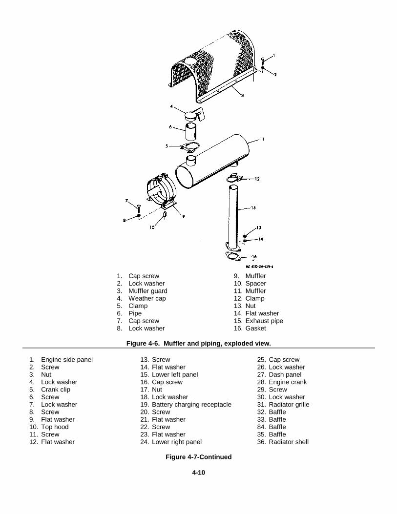
1. Cap screw 9. Muffler2. Lock washer 10. Spacer3. Muffler guard 11. Muffler4. Weather cap 12. Clamp5. Clamp 13. Nut6. Pipe 14. Flat washer7. Cap screw 15. Exhaust pipe8. Lock washer 16. Gasket
Figure 4-6. Muffler and piping, exploded view.
1. Engine side panel 13. Screw 25. Cap screw2. Screw 14. Flat washer 26. Lock washer3. Nut 15. Lower left panel 27. Dash panel4. Lock washer 16. Cap screw 28. Engine crank5. Crank clip 17. Nut 29. Screw6. Screw 18. Lock washer 30. Lock washer7. Lock washer 19. Battery charging receptacle 31. Radiator grille8. Screw 20. Screw 32. Baffle9. Flat washer 21. Flat washer 33. Baffle10. Top hood 22. Screw 84. Baffle11. Screw 23. Flat washer 35. Baffle12. Flat washer 24. Lower right panel 36. Radiator shell
Figure 4-7-Continued
4-10

Figure 4-7. Engine housing, exploded view
4-11

Section IX. MAINTENANCE OF FUEL SYSTEM
4-21. Descriptiona. The fuel tank (fig. 1-2) is mounted between the longitudinal members of the skid base at the fan end of the
engine. It incorporates a 3-way fuel source selector valve (1, fig. 2-4) to permit the engine to use the fuel from the fueltank or from an auxiliary source, whichever way the valve is operated. A fuel line connects the 3-way valve with the fuelpump.
b. The diaphragm-type, engine-driven fuel pump (17, fig. 4-8) is operated by a lobe on the camshaft.. It ismounted on the side of the
1. Spark plug 8. Fan guard 14. Primer lines2. Overspeed governor 9. Engine speed governor 15. Throttle control cable3. Engine lifting eye 10. Governor-to-throttle rod 16. Fuel strainer4. Exhaust manifold 11. Magneto 17. Fuel pump5. Shielded spark plug cables 12. Carburetor 18. Intake manifold6. Exhaust pipe 13. Choke control cable 19. Air intake hose7. Radiator hose
Figure 4-8. Left side of engine, identifying components.
4-12

engine. Fuel is pumped through a strainer (16) to thecarburetor (12), which is mounted on the intakemanifold. The carburetor provides a fuel-air mixture tothe engine, and has several adjustments for smoothengine operation.
c. The governor (9, fig. 4-8) controls the throttlecontrol of the carburetor (12) to provide the requiredengine speed, depending upon the setting of the manualthrottle. The engine will maintain the set speedregardless of load, provided the load applied does notexceed the horsepower rating of the engine. Severaladjustment points are provided to assure proper enginegovernor control.
d. The fuel system uses a primer pump and lineswhich aid starting in cold weather or after the engine hasbeen idle for a considerable length of time. The primerpump pumps raw fuel into the intake manifold to providefast starting.
4-22. Fuel Strainer, Fuel Lines, and Fittingsa. Fuel Strainer Service. If moisture or other
contaminants are visible through the glass bowl of thefuel strainer, service the fuel strainer as follows:
(1) Close the shutoff valve (6, fig. 4-9) on thefuel strainer.
(2) Loosen the nut on the bail (1) and swingthe bail aside to release the glass fuel bowl (2).Remove the bowl and gasket (3). Empty the contents ofthe bowl and wipe it dry with a clean cloth.
(3) If engine operation indicates that the filterelement (4) is contaminated, replace it with a new one.
(4) Position the gasket (3) and fuel bowl (2)on the fuel strainer housing (7). Swing the bail (1) intoposition and tighten the bail nut to hold the bowl inplace.
(5) Open the fuel shutoff valve (6) and checkfor leaks. Correct any leaks.
b. Removal. Remove the fuel strainer and the fuellines and fittings as shown in figure 4-10 and items 1through 7 of figure 4-11.
1. Bail 5 Filter gasket2. Fuel bowl 6 Fuel shutoff valve3. Bowl gasket 7. Fuel strainer housing4. Filter element
Figure 4-9. Fuel strainer, exploded view.
1. Screw 9. Tube nut2. Pointer 10. Adapter3 Screw 11. Fuel source selector4. Nut 3-way valve5. Lockwasher 12. Nipple6. Position plate 13. Elbow7. Tube 14. Bushing8. Tube nut
Figure 4-10. Fuel lines and fittings, exploded view.
4-13
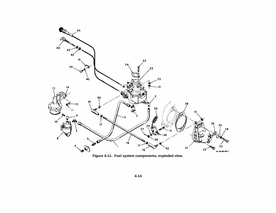
Figure 4-11. Fuel system components, exploded view.
4-14
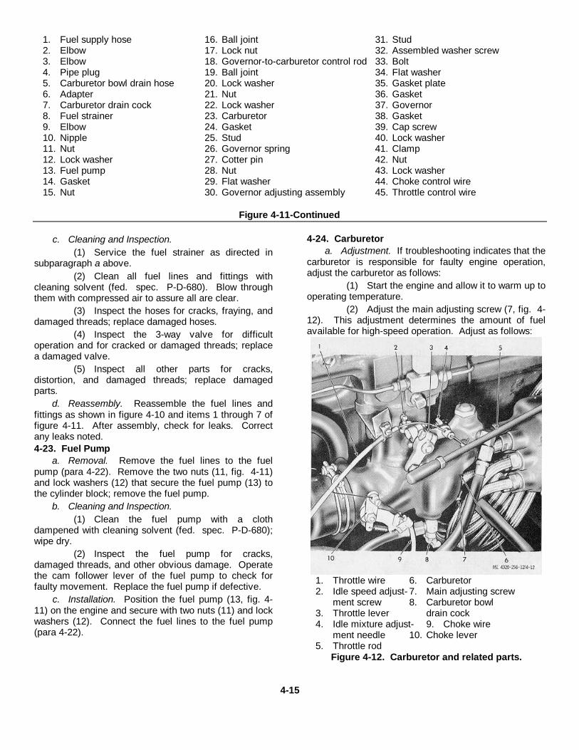
1. Fuel supply hose 16. Ball joint 31. Stud2. Elbow 17. Lock nut 32. Assembled washer screw3. Elbow 18. Governor-to-carburetor control rod 33. Bolt4. Pipe plug 19. Ball joint 34. Flat washer5. Carburetor bowl drain hose 20. Lock washer 35. Gasket plate6. Adapter 21. Nut 36. Gasket7. Carburetor drain cock 22. Lock washer 37. Governor8. Fuel strainer 23. Carburetor 38. Gasket9. Elbow 24. Gasket 39. Cap screw10. Nipple 25. Stud 40. Lock washer11. Nut 26. Governor spring 41. Clamp12. Lock washer 27. Cotter pin 42. Nut13. Fuel pump 28. Nut 43. Lock washer14. Gasket 29. Flat washer 44. Choke control wire15. Nut 30. Governor adjusting assembly 45. Throttle control wire
Figure 4-11-Continued
c. Cleaning and Inspection.(1) Service the fuel strainer as directed in
subparagraph a above.(2) Clean all fuel lines and fittings with
cleaning solvent (fed. spec. P-D-680). Blow throughthem with compressed air to assure all are clear.
(3) Inspect the hoses for cracks, fraying, anddamaged threads; replace damaged hoses.
(4) Inspect the 3-way valve for difficultoperation and for cracked or damaged threads; replacea damaged valve.
(5) Inspect all other parts for cracks,distortion, and damaged threads; replace damagedparts.
d. Reassembly. Reassemble the fuel lines andfittings as shown in figure 4-10 and items 1 through 7 offigure 4-11. After assembly, check for leaks. Correctany leaks noted.4-23. Fuel Pump
a. Removal. Remove the fuel lines to the fuelpump (para 4-22). Remove the two nuts (11, fig. 4-11)and lock washers (12) that secure the fuel pump (13) tothe cylinder block; remove the fuel pump.
b. Cleaning and Inspection.(1) Clean the fuel pump with a cloth
dampened with cleaning solvent (fed. spec. P-D-680);wipe dry.
(2) Inspect the fuel pump for cracks,damaged threads, and other obvious damage. Operatethe cam follower lever of the fuel pump to check forfaulty movement. Replace the fuel pump if defective.
c. Installation. Position the fuel pump (13, fig. 4-11) on the engine and secure with two nuts (11) and lockwashers (12). Connect the fuel lines to the fuel pump(para 4-22).
4-24. Carburetora. Adjustment. If troubleshooting indicates that the
carburetor is responsible for faulty engine operation,adjust the carburetor as follows:
(1) Start the engine and allow it to warm up tooperating temperature.
(2) Adjust the main adjusting screw (7, fig. 4-12). This adjustment determines the amount of fuelavailable for high-speed operation. Adjust as follows:
1. Throttle wire 6. Carburetor2. Idle speed adjust- 7. Main adjusting screw
ment screw 8. Carburetor bowl3. Throttle lever drain cock4. Idle mixture adjust- 9. Choke wire
ment needle 10. Choke lever5. Throttle rod
Figure 4-12. Carburetor and related parts.
4-15
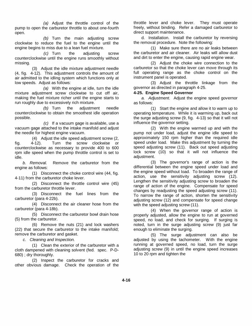
(a) Adjust the throttle control of thepump to open the carburetor throttle to about one-fourthopen.
(b) Turn the main adjusting screwclockwise to reduce the fuel to the engine until theengine begins to miss due to a lean fuel mixture.
(c) Turn the adjusting screwcounterclockwise until the engine runs smoothly withoutmissing.
(3) Adjust the idle mixture adjustment needle(4, fig. 4-12). This adjustment controls the amount ofair admitted to the idling system which functions only atlow speeds. Adjust as follows:
(a) With the engine at idle, turn the idlemixture adjustment screw clockwise to cut off air,making the fuel mixture richer until the engine starts torun roughly due to excessively rich mixture.
(b) Turn the adjustment needlecounterclockwise to obtain the smoothest idle operationpossible.
(c) If a vacuum gage is available, use avacuum gage attached to the intake manifold and adjustthe needle for highest engine vacuum.
(4) Adjust the idle speed adjustment screw (2,fig. 4-12). Turn the screw clockwise orcounterclockwise as necessary to provide 400 to 600rpm idle speed when the pump throttle control is set toidle.
b. Removal. Remove the carburetor from theengine as follows:
(1) Disconnect the choke control wire (44, fig.4-11) from the carburetor choke lever.
(2) Disconnect the throttle control wire (45)from the carburetor throttle lever.
(3) Disconnect the fuel lines from thecarburetor (para 4-22b).
(4) Disconnect the air cleaner hose from thecarburetor (para 4-18b).
(5) Disconnect the carburetor bowl drain hose(5) from the carburetor.
(6) Remove the nuts (21) and lock washers(22) that secure the carburetor to the intake manifold;remove the carburetor and gasket.
c. Cleaning and Inspection.(1) Clean the exterior of the carburetor with a
cloth dampened with cleaning solvent (fed. spec. P-D-680) ; dry thoroughly.
(2) Inspect the carburetor for cracks andother obvious damage. Check the operation of the
throttle lever and choke lever. They must operatefreely, without binding. Refer a damaged carburetor todirect support maintenance.
d. Installation. Install the carburetor by reversingthe removal procedure. Note the following:
(1) Make sure there are no air leaks betweenthe carburetor and air cleaner. Air leaks will allow dustand dirt to enter the engine, causing rapid engine wear.
(2) Adjust the choke wire connection to thecarburetor so that the choke lever can move through itsfull operating range as the choke control on theinstrument panel is operated.
(3) Adjust the throttle linkage from thegovernor as directed in paragraph 4-25.4-25. Engine Speed Governor
a. Adjustment. Adjust the engine speed governoras follows:
(1) Start the engine and allow it to warm up tooperating temperature. While it is warming up, back outthe surge adjusting screw (9, fig. 4-13) so that it will notinfluence the governor setting.
(2) With the engine warmed up and with thepump not under load, adjust the engine idle speed toapproximately 150 rpm higher than the required idlespeed under load. Make this adjustment by turning thespeed adjusting screw (11). Back out speed adjustinglock screw (10) so that it will not influence theadjustment.
(3) The governor's range of action is thedifferential between the engine speed under load andthe engine speed without load. To broaden the range ofaction, use the sensitivity adjusting screw (12).Lengthen the sensitivity adjusting screw to broaden therange of action of the engine. Compensate for speedchanges by readjusting the speed adjusting screw (11).To narrow the range of action, shorten the sensitivityadjusting screw (12) and compensate for speed changewith the speed adjusting screw (11).
(4) When the governor range of action isproperly adjusted, allow the engine to run at governedspeed, no load, and check for surging. If surging isnoted, turn in the surge adjusting screw (9) just farenough to eliminate the surging.
(5) The surge adjustment can also beadjusted by using the tachometer. With the enginerunning at governed speed, no load, turn the surgeadjusting screw (9) in until the engine speed increases10 to 20 rpm and tighten the
4-16

1. Magneto 5. Nut 10. Speed adjusting lock screw2. Nut 6. Throttle rod ball joint 11. Speed adjusting screw3. Magneto ground strap 7. Throttle operating lever 12. Sensitivity adjusting screw4. Governor-to-carburetor 8. Mounting screw 13. Governor spring
control rod 9. Surge adjusting screwFigure 4-13. Magneto and governor installation.
locking nut. If the carburetor and linkage are properlyadjusted, surge will disappear.
(6) When the governor adjustment iscompleted, tighten the speed adjusting lock screw (10)to lock the cam in position. Make sure all locking nutsare tightened.
b. Removal.(1) Disconnect the ball joint (16, fig. 4-11) on
governor-to-carburetor control rod (18) from the lever onthe governor.
(2) Remove the governor and related parts asshown in items 27 through 37, figure 4-11.
c. Cleaning and Inspection.(1) Clean the exterior of the governor with a
cloth dampened with cleaning solvent (fed. spec. P-D-680). Wipe dry.
(2) Clean all remaining parts with cleaningsolvent (fed. spec. P-D-680) ; dry thoroughly.
(3) Inspect the governor for cracks, andmissing parts, wear, and other obvious damage. Checkthe rotation of the governor drive shaft. It must turnfreely without catching or binding. Check the movementof the governing shaft in its needle bearings. It mustpivot freely without catching or binding and withoutexcessive play. Refer a damaged governor to directsupport maintenance.
d. Installation.(1) Install the governor by reversing the removalprocedure. Refer to items 27 through 37 in figure 4-11.(2) Adjust the governor as directed in sub-paragraph aabove.4-26. Primer Pump, Lines, and Fittings
a. Removal. Remove the primer pump, lines, andfittings as shown in figure 4-14.
b. Cleaning and Inspection.(1) Clean the exterior of the primer pump with
a cloth dampened with cleaning solvent
4-17

1. Tube 5. Bushing 9. Tee2. Bushing 6. Tee 10. Tube3. Elbow 7. Tee 11. Elbow4. Tube 8. Tube 12. Primer pump
Figure 4-14. Primer pump, lines, and fittings, exploded view.
4-18

(fed. spec. P-D-680). Pump clean solvent through thepump to thoroughly flush the interior.
(2) Clean all lines and fittings with cleaningsolvent (fed. spec. P-D-680). Blow out all lines withcompressed air to make sure they are not clogged.
(3) Check the exterior of the primer pump forcracks or obvious damage. Operate the pump handle.Make sure it operates freely without binding. Replace adamaged priming pump.
(4) Inspect the primer tubes for damagedthreads on tube nuts, kinked tubing, cracked tubingends, or other damage. Replace damaged tubes.
(5) Inspect all fittings for cracks, damagedthreads, and other damage; replace damaged parts.
c. Installation. Install the primer pump, lines, andfittings as shown in figure 4-14. After installation,operate the primer pump and check all connections forleaks. Correct any leaks.
Section X. MAINTENANCE OF COOLING SYSTEM4-27. Description
a. The engine cooling system is a conventionalautomotive type in which coolant is circulated throughthe cylinder block to remove the heat of combustionfrom the operating parts of the engine. The coolant isthen passed through the radiator, which acts as a largeheat exchanger to dissipate the heat to the atmosphere.The water pump maintains the flow of coolant throughthe engine.
b. A thermostat is installed in the engine to preventthe flow of coolant into the radiator when the engine iscold. Instead, the coolant is bypassed directly to thewater pump and recirculated into the block without beingcooled in the radiator. In this way, the engine heatsmore rapidly, providing efficient operation more quickly.When the coolant in the cylinder block reachesoperating temperature, the thermostat opens and thecoolant is forced to flow through the radiator.
c. To assure efficient operation of the coolingsystem, it is important to keep the exterior of theradiator clean and free from bugs, dirt, and debris. It isalso necessary to keep the interior of the radiator andthe engine block flushed out to prevent accumulations ofrust and scale which can prevent proper heat transfer.4-28. Cleaning and Flushing the Cooling System
a. Clean the exterior of the radiator by flushing astream of water through it in a direction opposite that ofthe cooling fan flow. Since this engine uses a pushertype fan, it is necessary to squirt the water from theoutside of the radiator inward toward the engine. Coverthe engine with a piece of plastic film to preventsaturating the components before attempting to flush outthe exterior of the radiator.
b. Disconnect the hoses connecting the engine andradiator. With the radiator cap closed tightly, use aflushing gun as shown in figure 4-15 to reverse-flush theradiator. Fill the radiator with water, then blow it out withcompressed air, applying pressure slowly to preventradiator damage. Repeat several times until theexpelled flushing stream is clear.
c. Remove the thermostat (para 4-29) from theengine and use a flushing gun as shown in figure 4-16.Fill the cylinder block with water before applying airpressure. When the block is filled, expel the water withan 80 psi air stream. Repeat until the expelled flushingstream is clear.
Figure 4-15. Reverse-flushing the radiator.
4-19

Figure 4-16. Reverse-flushing tee engine block.
d. Install the thermostat and connect the hosesbetween the engine and radiator (para 4-29). Start theengine and allow to run until the coolant reachesoperating temperature. Check for coolant leaks andcorrect if any are noted.4-29. Thermostat, Outlet Elbow, Lines, and Fittings
a. Removal.(1) Drain the radiator and block (para 2-3f).(2) Remove and disassemble the thermostat,
outlet elbow, lines, and fittings as shown in figure 4-17.b. Cleaning, Inspection, and Thermostat Testing.
(1) Clean all parts by washing in warm, soapywater. Remove any greasy or gummy deposits with acloth dampened with cleaning solvent (fed. spec. P-D-680) ; dry thoroughly.
(2) Inspect the thermostat for obviousdefects, including ruptured bellows and distortion. If thevalve, when cold, can be pushed off its seat with onlyslight effort, the thermostat is defective and must bereplaced.
(3) Check the thermostat operation asfollows:
(a) Hang the thermostat by its frame ina container of water so that it does not touch thecontainer. Hang a thermometer in the container tomaintain a check of water temperature.
(b) Heat the water slowly whilewatching the thermometer and thermostat. Thethermostat must start to open before the thermometerindicates 180° F. Replace the thermostat if it fails toopen at 180° F or if it opens at too low a temperature.
(4) Inspect the water outlet elbow for cracks,damaged threads, and distortion; replace a damagedelbow.
(5) Inspect the hoses for cracks, cuts,deterioration, brittleness, and other damage; replacedamaged hoses.
(6) Inspect all other parts for cracks,distortion, and other damage; replace damaged parts.
c. Installation. Installation of the thermostat, outletelbow, hoses, and fittings is the reverse of removal.Refer to figure 4-14. Service the coolant and enginelubrication systems. After installation, run the engineuntil it reaches operating temperature, and check forleaks. Correct any leaks noted.4-30. Water Pump, Cooling Fan and Fan Belt
a. Fan Belt Adjustment. The fan belt should betensioned so that it can be deflected approximately 3/4inch with thumb pressure at a point midway betweenpulleys at the longest belt span. Adjust belt tension asfollows:
(1) Loosen the alternator strap mountingscrew (5, fig. 4-18).
(2) Loosen the adjusting screw (3) on theadjusting strap (2) and pull the alternator (1) away fromthe engine with hand pressure to tighten the fan belt (4).
(3) Hold the alternator away from the engineand tighten the adjusting screw (3). Recheck fan belttension and readjust if necessary. Tighten the strapmounting screw (5) after proper adjustment is made.
b. Removal.(1) Loosen the adjusting screw (3, fig. 4-18)
on the alternator adjusting strap and push the alternatortoward the engine to loosen fan belt tension. Slip thefan belt (4) off the alternator drive pulley and disengageit from the fan and pulley.
(2) Remove the four cap screws (1, fig. 4-19)and lock washers (2) that secure the cooling fan (3) tothe pulley on the water pump; remove the cooling fan.
4-20

1. Drain plug 16. Radiator drain tube 30. Bushing2. Drain plug 17. Connector 31. Cooler-to-crankcase hose3. Drain plug 18. Hose clamp 32. Elbow4. Drain plug 19. Hose 33. Oil cooler drain hose5. Hose clamp 20. Hose clamp 34. Bushing6. Hose 21. Elbow 35. Elbow7. Bypass tube 22. Hose 36. Bushing8. Connector 23. Hose clamp 37. Tee9. Plug 24. Drain elbow 38. Nipple10. Nut 25. Hose 39. Elbow11. Lock washer 26. Crankcase-to-cooler hose 40. Bushing12. Water outlet elbow 27. Elbow 41. Crankcase coolant drain hose13. Gasket 28. Bypass valve 42. Bushing14. Thermostat 29. Nipple 43. Bushing15. Thermostat ring
Figure 4-17. Thermostat, outlet elbow, coolant and oil cooler lines and fittings, exploded view.(3) Drain the coolant from the radiator and
cylinder block. Disconnect coolant hoses and by-passtube from the water pump (para 4-29). Remove thethree cap screws (4, 6, and 8) and lock washers (5, 7,and 9) that secure the water pump (10) to the cylinderblock; remove the water pump and gasket (11).
c. Cleaning and Inspection.(1) Clean the fan belt with a clean, dry cloth.
(2) Clean the cooling fan and water pumpwith a cloth dampened with cleaning solvent (fed. spec.P-D-680) ; dry thoroughly.
(3) Inspect the fan belt for cracks, brittleness,severe glazing, and other damage; replace a damagedfan belt.
(4) Inspect the cooling fan for cracked, bent,loose, or severely nicked fan blades, damaged orelongated mounting holes, or other damage; replace adamaged cooling fan.
4-21

1. Alternator 4. Fan belt2. Adjusting strap 5. Strap mounting screw3. Adjusting screw
Figure 4-18. Alternator mounting.
(5) Inspect the water pump for a cracked ordistorted housing, damaged mounting flanges, and otherdamage. Check the rotation of the water pump shaft. Itmust rotate easily without catching or binding. Refer adamaged water pump to direct support maintenance.
d. Installation.(1) Installation of the water pump and cooling
fan is the reverse of removal. Refer to figure 4-19.(2) Install the fan belt on the pulleys and
tighten to the required tension (subparagraph a above).4-31. Radiator
a. Removal.(1) Drain the radiator and oil cooler, and
remove the coolant and oil cooler lines from the radiator(para 4-29).
(2) Remove the engine housing as necessaryto provide access to the radiator for removal. Refer toparagraph 4-20a.
(3) Remove the fan guard (3, fig. 220),supports (6 and 7), and fan shroud (11).
1. Cap screw 5. Lock washer 9. Lock washer2. Lock washer 6. Cap screw 10. Water pump3. Cooling fan 7. Lock washer 11. Gasket4. Cap screw 8. Cap screw
Figure 4-19. Water pump and cooling fan, exploded view.
4-22

1. Cap screw 11. Fan shroud2. Flat washer 12. Nut3. Fan guard 13. Lock washer4. Machine screw 14. Liner5. Lock washer 15. Nut6. Radiator support 16. Lock washer7. Radiator support 17. Crank support8. Machine screw 18. Spacer9. Lock washer 19. Radiator cap10. Flat washer 20. RadiatorFigure 4-20. Radiator and related parts, exploded
view.
(4) Use a rope sling and support the weight ofthe radiator with a hoist before removing the nuts (12)and lock washers (13) that secure the radiator (20) tothe engine support; remove the radiator.
b. Cleaning and Inspection.(1) Thoroughly flush the radiator with water,
both inside and out. Make sure all bugs and debris areremoved from the cooling fins.
(2) Inspect the radiator for cracks, damagedcooling fins, leaking tubes, leaks around the top bonnet,and other damage. Refer a damaged radiator to directsupport maintenance for repair.
(3) Inspect the fan guard and fan shroud forcracks, broken weldments, distortion, and otherdamage. Replace damaged parts.
c. Installation.(1) Installation is the reverse of the removal
procedure. Refer to figure 4-20.(2) Install the coolant and oil cooler lines and
fittings (para 4-29).(3) Install the engine housing panels that
were removed to provide access to the radiator (para 4-20c).
(4) Service the engine coolant system endthe engine oil system. Start the engine and check forleaks. Correct any deficiencies.
Section XI. MAINTENANCE OF IGNITION SYSTEM4-32. Description
a. The ignition system includes the magneto (11,fig. 4-8) and radio-surpressed spark plugs (1) whichhave shielded cables (5). The system is completelyindependent of the battery- and alternator-poweredelectrical system.
b. The magneto is timed t) the engine and isdriven by the camshaft gear through the governor drivegear which is engaged by the drive lugs on the magnetodrive coupling. There is a critical timing relationshipbetween these driving parts since it determines theinstant at which the spark from the magneto will be
delivered to each spark plug. An improperly timedmagneto will make engine operation impossible.
c. The magneto consists of a magneto rotor whichis rotated in a laminated frame to set up magnetic flux inthe laminated frame. This induces a current in theprimary winding each time the magnetic flux rises andfalls. The primary winding acts as the primary windingof a step-up transformer, surrounded by the secondarycoil. Breaker point opening occurs at the instant ofmaximum primary current, causing an immediatecollapse of the magnetic field. This collapsing magneticfield induces an extremely high voltage surge throughthe secondary circuit. The capaci-
4-23

tor in the primary circuit speeds the collapse of thecircuit, increasing the secondary voltage and alsoreducing contact point burning.
d. The voltage induced in the secondary coil isapplied to the spark plug of the required cylinder at theexact correct instant by the distributor rotor in themagneto. The breaker points open at the requiredinstant to assure a hot spark to the spark plug at thistime. The spark at the spark plug causes the ignition ofthe fuel-air mixture in the cylinder.
e. At starting, an impulse coupling on the magnetocauses a snapping action of the magneto rotor toproduce the rapid rotation necessary to energize theelectrical windings. This retards the rotation of themagneto rotor at slow speeds until top-dead-center isreached. Spring action then snaps the rotor forward toproduce the required snap.
f. The magneto also contains automatic sparkadvance provisions so that the spark will occur soonerduring high speed operation. This is necessary forsmooth engine performance. The automatic sparkadvance rotor has pawls which are thrown outward asengine speed increases to change the relationship of thedistributor rotor in the magneto.4-33. Spark Plugs
a. Removal.(1) Use compressed air to blow dirt away
from the spark plugs before removing them. This willprevent the dirt from entering the cylinder as the sparkplug is removed.
(2) Disconnect the shielded spark plug cablesfrom the spark plugs (13, fig. 4-21) and remove thespark plugs, using a socket wrench.
b. Cleaning and Inspection.Note
It is normally more economical toreplace the spark plugs than to cleanand regap them. It also providesgreater assurance that there are nohidden cracks in the ceramicinsulators which could cause enginemisfiring at high engine speeds.Cleaning and inspection instructionsare given here in case it is necessaryto reuse the removed plugs.
(1) Wipe the exterior of the spark plugs with acloth dampened with cleaning solvent (fed. spec. P-D-680); dry thoroughly.
(2) Check the ceramic insulator for cracks,porosity, and other damage.
(3) If the electrodes of the spark plugs are nottoo badly burned, remove the scale and other depositsfrom them. This can be done by a sandblast-typecleaner or with a contact file.
(4) Inspect the electrodes for severe burning,cracks, and other damage. If it is necessary to reusethe plugs, correct the contact gap to 0.025 inch.
(5) Replace any spark plugs whose conditionis doubtful.
c. Installation.(1) Make sure all spark plugs are gapped to
0.025 inch before installation.(2) Install the spark plugs, using a socket and
torque wrench. Tighten the spark plugs to 35 foot-pounds torque.
(3) Install the shielded spark plug cables onthe spark plugs. Make sure the leads are notinterchanged. Refer to figure 4-22 to assure propermagneto-to-spark plug wiring if spark plug connection isdoubtful.4-34. Magneto
a. Removal.(1) Disconnect the shielded spark plug cables
from the magneto. Disconnect the primary lead to themagneto.
(2) Remove the lower cap screw (19, fig. 4-21) and lock washers (20 and 22), and flat washer (21)that secure the bottom of the magneto to the enginefront plate. Remove the nut (16) and lock washer (17)from the bolt (33, fig. 4-11) that secures the groundstrap (18, fig. 4-21), the top of the magneto, and the topof the engine speed governor to the gear cover; removethe magneto (23), gasket (24), and spacer (25).
b. Replacing and Adjusting Breaker PointAssembly.
(1) Remove the screws (1 and 2, fig. 4-23)and lock washers (3) that secure the distributor housing(7) to the magneto frame. Pull the distributor housingaway from the frame far enough to disconnect thecapacitor lead from the terminal on the breaker pointassembly. Remove the distributor housing. Removeand discard the distributor housing gasket (6).
(2) Use a spanner wrench to remove thecapacitor (4) from the distributor housing and removethe preformed packing (5). Discard both parts.
(3) Remove the nut that secures the coil leadto the breaker point assembly (14) and disconnect thelead.
(4) Remove the two screws (10 and 11), lockwashers (12), and flat washer (13) that secure thebreaker point assembly to the rotor bearing plate (28);remove the breaker point assembly.
4-24

1. No. 6 spark plug cable 10. Bracket 18. Ground strap2. No. 5 spark plug cable 11. Grommet 19. Cap screw3. No. 4 spark plug cable 12. Bracket 20. Lock washer4. No. 3 spark plug cable 13. Spark plug 21. Flat washer5. No. 2 spark plug cable 14. Cap screw 22. Lock washer6. No. 1 spark plug cable 15. Lock washer 23. Magneto7. Grommet 16. Nut 24. Gasket8. Bracket 17. Lock washer 25. Magneto spacer9. Grommet
Figure 4-21. Ignition system, exploded view.
(5) Remove the distributor gear (8). Remove the retaining ring (15) and use two screwdrivers inserted underopposite sides of the rotor shaft gear (17) to pry the assembled gear and breaker cam assembly (16) from the rotor shaft(33). The cam also acts as a key for the gear.
(6) Make sure the gear mounting surface of the rotor shaft is clean. Install the rotor shaft gear (17) and camassembly (16) on the shaft.Secure with the retaining ring (15). Apply a light coat of grease on the cam lobes. The grease is provided in the breakerpoint kit.
(7) Apply one drop of SAE 20 lubricating oil on the shaft bushings for the distributor gear.
4-25
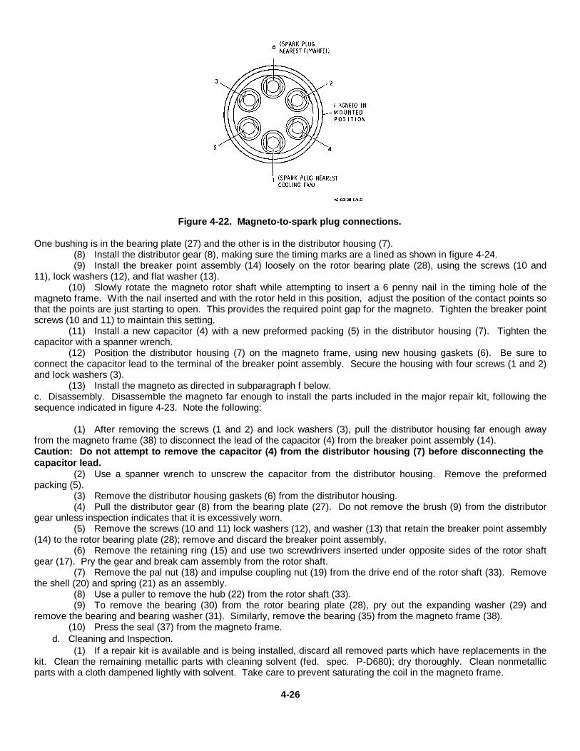
Figure 4-22. Magneto-to-spark plug connections.
One bushing is in the bearing plate (27) and the other is in the distributor housing (7).(8) Install the distributor gear (8), making sure the timing marks are a lined as shown in figure 4-24.(9) Install the breaker point assembly (14) loosely on the rotor bearing plate (28), using the screws (10 and
11), lock washers (12), and flat washer (13).(10) Slowly rotate the magneto rotor shaft while attempting to insert a 6 penny nail in the timing hole of the
magneto frame. With the nail inserted and with the rotor held in this position, adjust the position of the contact points sothat the points are just starting to open. This provides the required point gap for the magneto. Tighten the breaker pointscrews (10 and 11) to maintain this setting.
(11) Install a new capacitor (4) with a new preformed packing (5) in the distributor housing (7). Tighten thecapacitor with a spanner wrench.
(12) Position the distributor housing (7) on the magneto frame, using new housing gaskets (6). Be sure toconnect the capacitor lead to the terminal of the breaker point assembly. Secure the housing with four screws (1 and 2)and lock washers (3).
(13) Install the magneto as directed in subparagraph f below.c. Disassembly. Disassemble the magneto far enough to install the parts included in the major repair kit, following thesequence indicated in figure 4-23. Note the following:
(1) After removing the screws (1 and 2) and lock washers (3), pull the distributor housing far enough awayfrom the magneto frame (38) to disconnect the lead of the capacitor (4) from the breaker point assembly (14).Caution: Do not attempt to remove the capacitor (4) from the distributor housing (7) before disconnecting thecapacitor lead.
(2) Use a spanner wrench to unscrew the capacitor from the distributor housing. Remove the preformedpacking (5).
(3) Remove the distributor housing gaskets (6) from the distributor housing.(4) Pull the distributor gear (8) from the bearing plate (27). Do not remove the brush (9) from the distributor
gear unless inspection indicates that it is excessively worn.(5) Remove the screws (10 and 11) lock washers (12), and washer (13) that retain the breaker point assembly
(14) to the rotor bearing plate (28); remove and discard the breaker point assembly.(6) Remove the retaining ring (15) and use two screwdrivers inserted under opposite sides of the rotor shaft
gear (17). Pry the gear and break cam assembly from the rotor shaft.(7) Remove the pal nut (18) and impulse coupling nut (19) from the drive end of the rotor shaft (33). Remove
the shell (20) and spring (21) as an assembly.(8) Use a puller to remove the hub (22) from the rotor shaft (33).(9) To remove the bearing (30) from the rotor bearing plate (28), pry out the expanding washer (29) and
remove the bearing and bearing washer (31). Similarly, remove the bearing (35) from the magneto frame (38).(10) Press the seal (37) from the magneto frame.
d. Cleaning and Inspection.(1) If a repair kit is available and is being installed, discard all removed parts which have replacements in the
kit. Clean the remaining metallic parts with cleaning solvent (fed. spec. P-D680); dry thoroughly. Clean nonmetallicparts with a cloth dampened lightly with solvent. Take care to prevent saturating the coil in the magneto frame.
4-26

1. Screw 14. Breaker point assembly 27. Bearing plate2. Screw 15. Retaining ring 28. Rotor bearing plate3. Lock washer 16. Breaker cam assembly 29. Expanding washer4. Capacitor 17. Rotor shaft gear 30. Rotor bearing5. Preformed packing 18. Pal nut 31. Bearing washer6. Housing gasket 19. Impulse coupling nut 32. Shim7. Distributor housing 20. Shell 33. Rotor shaft8. Distributor gear 21. Impulse coupling spring 34. Expanding washer9. Distributor gear brush 22. Impulse coupling hub 35. Rotor bearing10. Screw 23. Key 36. Bearing washer11. Screw 24. Screw 37. Shaft seal12. Lock washer 25. Screw 38. Magneto frame13. Washer 26. Lock washer
Figure 4-23. Magneto, exploded view.(2) Inspect the distributor housing for cracks, burned terminals, signs of arcing, and other damage.(3) Inspect the bearing plate for cracks, distortion, and wear. There shall be no perceptible play between the
shaft of the distributor gear and the bearing plate bushing.(4) Inspect the rotor shaft for damaged seal and bearing seats, loss of magnetism, and damaged threads.(5) Inspect all coupling parts for obvious damage.(6) Inspect the magneto frame for cracks, distortion, and damaged threads. Check that the coil is firmly
wedged in the frame. Drive the wedges in if necessary to tighten the coil. Check the coil for damaged insulation,gouges, and other damage.
(7) If any non-kitted parts other than hardware are damaged, replace the magneto as an assembly.
e. Reassembly. During reassembly, install all of the new parts that are contained in the repair kit, to replace theparts which were removed from
4-27
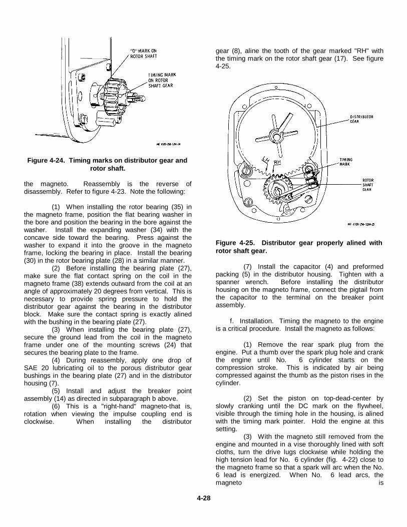
Figure 4-24. Timing marks on distributor gear androtor shaft.
the magneto. Reassembly is the reverse ofdisassembly. Refer to figure 4-23. Note the following:
(1) When installing the rotor bearing (35) inthe magneto frame, position the flat bearing washer inthe bore and position the bearing in the bore against thewasher. Install the expanding washer (34) with theconcave side toward the bearing. Press against thewasher to expand it into the groove in the magnetoframe, locking the bearing in place. Install the bearing(30) in the rotor bearing plate (28) in a similar manner.
(2) Before installing the bearing plate (27),make sure the flat contact spring on the coil in themagneto frame (38) extends outward from the coil at anangle of approximately 20 degrees from vertical. This isnecessary to provide spring pressure to hold thedistributor gear against the bearing in the distributorblock. Make sure the contact spring is exactly alinedwith the bushing in the bearing plate (27).
(3) When installing the bearing plate (27),secure the ground lead from the coil in the magnetoframe under one of the mounting screws (24) thatsecures the bearing plate to the frame.
(4) During reassembly, apply one drop ofSAE 20 lubricating oil to the porous distributor gearbushings in the bearing plate (27) and in the distributorhousing (7).
(5) Install and adjust the breaker pointassembly (14) as directed in subparagraph b above.
(6) This is a "right-hand" magneto-that is,rotation when viewing the impulse coupling end isclockwise. When installing the distributor
gear (8), aline the tooth of the gear marked "RH" withthe timing mark on the rotor shaft gear (17). See figure4-25.
Figure 4-25. Distributor gear properly alined withrotor shaft gear.
(7) Install the capacitor (4) and preformedpacking (5) in the distributor housing. Tighten with aspanner wrench. Before installing the distributorhousing on the magneto frame, connect the pigtail fromthe capacitor to the terminal on the breaker pointassembly.
f. Installation. Timing the magneto to the engineis a critical procedure. Install the magneto as follows:
(1) Remove the rear spark plug from theengine. Put a thumb over the spark plug hole and crankthe engine until No. 6 cylinder starts on thecompression stroke. This is indicated by air beingcompressed against the thumb as the piston rises in thecylinder.
(2) Set the piston on top-dead-center byslowly cranking until the DC mark on the flywheel,visible through the timing hole in the housing, is alinedwith the timing mark pointer. Hold the engine at thissetting.
(3) With the magneto still removed from theengine and mounted in a vise thoroughly lined with softcloths, turn the drive lugs clockwise while holding thehigh tension lead for No. 6 cylinder (fig. 4-22) close tothe magneto frame so that a spark will arc when the No.6 lead is energized. When No. 6 lead arcs, themagneto is
4-28

at the No. 6 firing position. Hold the magneto drive shaft at this position.
(4) Check the governor drive gear to make sure that the punch-marked tooth in the cam gear is engagedbetween the two punch-marked teeth on the governor drive gear.
(5) Remove the magneto from the vise. Turn the magneto drive lugs of the impulse couplingcounterclockwise about one-quarter turn so that the lugs will mesh with the drive members of the governor drive gear.Position the magneto (23, fig. 4-21), spacer (25), and gasket (24) on the engine with the magneto lugs engaged andtighten the mounting bolts moderately. Connect the spark plug cables.
(6) Start the engine and idle it at 600 rpm.If the engine fails to start, it is probably due to faulty ignition timing. Recheck as directed above.
(7) With the engine running at 600 rpm, use a timing light connected to the rear spark plug and check that theIGN-M indication on the flywheel is alined with the timing pointer. If it is not exactly alined, rotate the magneto slightlyuntil the correct indication is attained. Tighten the mounting bolts firmly.
Section Xll. MAINTENANCE OF ELECTRICAL SYSTEM
4-35. Descriptiona. The electrical system includes the battery box which houses two 12-volt, lead-acid-type storage batteries (3, fig.
4-1) connected in series to power the 24-volt electrical system. Battery output is used to energize the electrical starter (7,fig. 4-26) to start the engine. The battery charge is partially depleted as the engine is started and is restored by thebattery charging system consisting of the alternator (1) and voltage regulator (10).
b. The alternator and regulator are typical automotive type in which the alternator output is controlled through thevoltage regulator, depending upon the state of charge of the battery.When the battery charge is low, the voltage regulator increases the strength of the alternator field to increase the outputof the alternator. When the battery charge is normal, the output of the alternator decreases to near zero.
c. Reverse polarity connections to an alternator can severely damage the alternator. To prevent this damage, thesystem is protected by a reverse polarity protector (9) which is mounted on the panel next to the voltage regulator.
Caution: Though this engine is equipped with a reverse polarity protector to protect the alternator againstdamage due to reverse polarity connections, it is good practice to take special precautions when connectingand disconnecting electrical leads and cables. Do not ground the field terminal between the alternator andregulator. Do not operate the alternator in an open circuit with the rotor winding energized. Do not ground thealternator output circuit. Take care to prevent reversing polarity of the electrical system. When using a batterybooster or fast charger, make sure the leads are connected with proper polarity. Failure to follow theseinstructions may damage the alternator rectifiers, voltage regulator, and wiring.
d. The engine starter (7, fig. 4-26) is a solenoid-operated type in which the soleonid switch (6) is mounted on thetop of the starter. The solenoid switch uses electrical energy to pull the starter drive into engagement with the flywheelring gear and to make the electrical circuit which energizes the starter after the drive is engaged. When the enginestarts, the starter drive is disengaged, preventing the engine from driving the starter since engine operating speeds couldseverely damage the starter. Reengagement of the starter while the engine is running is prohibited by the starterdisengage relay (para 4-42e).
4-36. Battery Charging Circuit Testing
Note. To determine if the alternator and voltage regulator are producing proper output to maintain the proper batterycharge, perform the on-engine tests described in this paragraph.
a. Battery Voltage and Shorted Isolation Diode Tests. These tests determine if the batteries are properly connectedto the alternator and if the isolation diode is shorted. A shorted isolation diode will discharge the battery through thevoltage regulator to ground.
(1) With the engine stopped, the battery disconnect switch positioned to ON, and the ignition switch positionedto OFF, the electrical circuit will be as shown in figure 4-27.
(2) With a voltmeter, check the voltage across the negative output terminal of the alternator and the positiveterminal of the one battery which does not have its negative terminal grounded. Note the voltage. It should be 24.0 to25.2 volts.
4-29

1. Alternator 5. Water temperature sender 9. Reverse polarity protector2. Oil pressure sender 6. Starter solenoid switch 10. Voltage regulator3. Oil filter 7. Engine starter 11. Engine oil filler cap4. Engine overspeed governor 8. Oil level dipstick
Figure 4-26. Right side of engine, showing components.
(3) Move the voltmeter probe from the positive battery terminal to the positive output terminal of thealternator. It must be the same as the voltage to the positive battery terminal. If it is not, check for loose cableconnections or damaged cables.
(4) Move the voltmeter probe from the positive terminal to the regulator terminal of the alternator. Thevoltmeter must register zero voltage. If it registers a voltage higher than zero, it indicates a shorted isolation diode in thealternator, or possibly an output cable terminal touching the heat sink. If more than zero is still registered after the outputcable is repositioned, replace the alternator.
b. Open Isolation Diode Test. This test deter
4-30
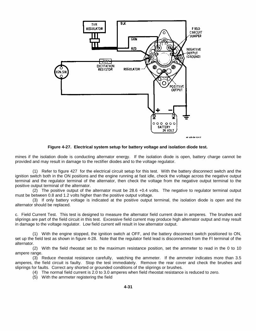
Figure 4-27. Electrical system setup for battery voltage and isolation diode test.
mines if the isolation diode is conducting alternator energy. If the isolation diode is open, battery charge cannot beprovided and may result in damage to the rectifier diodes and to the voltage regulator.
(1) Refer to figure 427 for the electrical circuit setup for this test. With the battery disconnect switch and theignition switch both in the ON positions and the engine running at fast idle, check the voltage across the negative outputterminal and the regulator terminal of the alternator, then check the voltage from the negative output terminal to thepositive output terminal of the alternator.
(2) The positive output of the alternator must be 28.6 +0.4 volts. The negative to regulator terminal outputmust be between 0.8 and 1.2 volts higher than the positive output voltage.
(3) If only battery voltage is indicated at the positive output terminal, the isolation diode is open and thealternator should be replaced.
c. Field Current Test. This test is designed to measure the alternator field current draw in amperes. The brushes andsliprings are part of the field circuit in this test. Excessive field current may produce high alternator output and may resultin damage to the voltage regulator. Low field current will result in low alternator output.
(1) With the engine stopped, the ignition switch at OFF, and the battery disconnect switch positioned to ON,set up the field test as shown in figure 4-28. Note that the regulator field lead is disconnected from the Fl terminal of thealternator.
(2) With the field rheostat set to the maximum resistance position, set the ammeter to read in the 0 to 10ampere range.
(3) Reduce rheostat resistance carefully, watching the ammeter. If the ammeter indicates more than 3.5amperes, the field circuit is faulty. Stop the test immediately. Remove the rear cover and check the brushes andsliprings for faults. Correct any shorted or grounded conditions of the sliprings or brushes.
(4) The normal field current is 2.0 to 3.0 amperes when field rheostat resistance is reduced to zero.(5) With the ammeter registering the field
4-31
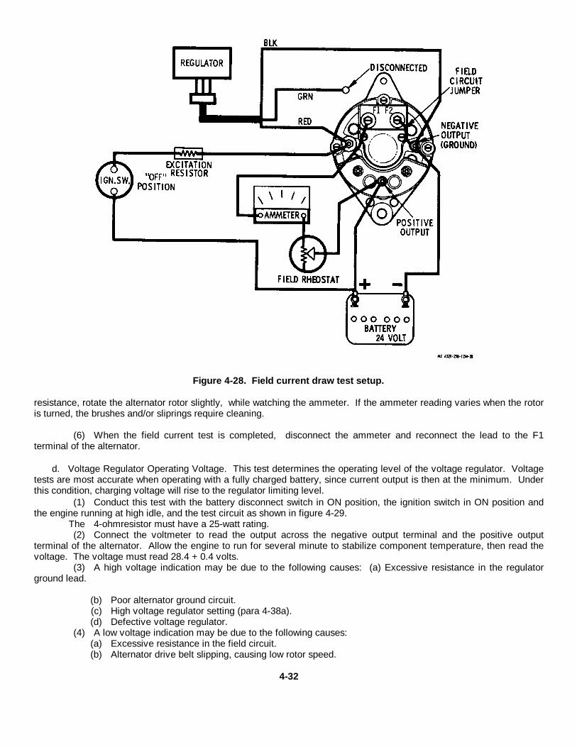
Figure 4-28. Field current draw test setup.
resistance, rotate the alternator rotor slightly, while watching the ammeter. If the ammeter reading varies when the rotoris turned, the brushes and/or sliprings require cleaning.
(6) When the field current test is completed, disconnect the ammeter and reconnect the lead to the F1terminal of the alternator.
d. Voltage Regulator Operating Voltage. This test determines the operating level of the voltage regulator. Voltagetests are most accurate when operating with a fully charged battery, since current output is then at the minimum. Underthis condition, charging voltage will rise to the regulator limiting level.
(1) Conduct this test with the battery disconnect switch in ON position, the ignition switch in ON position andthe engine running at high idle, and the test circuit as shown in figure 4-29.
The 4-ohmresistor must have a 25-watt rating.(2) Connect the voltmeter to read the output across the negative output terminal and the positive output
terminal of the alternator. Allow the engine to run for several minute to stabilize component temperature, then read thevoltage. The voltage must read 28.4 + 0.4 volts.
(3) A high voltage indication may be due to the following causes: (a) Excessive resistance in the regulatorground lead.
(b) Poor alternator ground circuit.(c) High voltage regulator setting (para 4-38a).(d) Defective voltage regulator.
(4) A low voltage indication may be due to the following causes:(a) Excessive resistance in the field circuit.(b) Alternator drive belt slipping, causing low rotor speed.
4-32

Figure 4-29. Voltage regulator operating voltage test setup.
(c) Low voltage regulator setting (para 4-38a).(d) Defective regulator.
(5) Correct the cause of the overvoltage or undervoltage condition and recheck the voltage regulator operating voltage.When tests are completed, disconnect the 1/4-ohm resistor from the circuit.
e. Alternator Output and System Test.
(1) Conduct this test with the battery disconnect switch in ON position, the ignition switch in ON position, theengine running, and the equipment set up as shown in figure 4-30. At the start, set the carbon pile resistor to minimumcurrent drain. The ammeter must be adjusted to read in the 0 to 100 ampere scale.
(2) With the engine running at fast idle, adjust the carbon pile to provide a 20-ampere charge rate. Maintainthis for a few minutes to warm up the components.
(3) Use a tachometer to check the alternator speed. Adjust engine speed to maintain an alternator speed of3000 to 5000 rpm.
(4) Adjust the carbon pile rheostat to attain a maximum current reading on the ammeter.Maximum current output must be 30 amperes minimum, at 25 to 28 volts.
Caution: Unload the carbon pile rheostat immediately after completion of the test to prevent discharge ofthe battery.
(5) Readjust the carbon pile rheostat for a 10-ampere output of the alternator. Check the voltage dropbetween the alternator and battery at this output. If the voltage drop exceeds 0.3 volt, check battery cable connectionsfor high resistance connections.
4-37. AlternatorCaution: Disconnect the battery cable (6, fig.4-1) from the positive battery terminal (4) before disconnecting anyother leads from the engine components. This will prevent shorts which
4-33
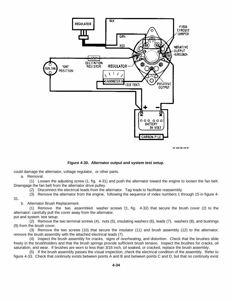
Figure 4-30. Alternator output and system test setup.
could damage the alternator, voltage regulator, or other parts.a. Removal.
(1) Loosen the adjusting screw (1, fig. 4-31) and push the alternator toward the engine to loosen the fan belt.Disengage the fan belt from the alternator drive pulley.
(2) Disconnect the electrical leads from the alternator. Tag leads to facilitate reassembly.(3) Remove the alternator from the engine, following the sequence of index numbers 1 through 15 in figure 4-
31.b. Alternator Brush Replacement.
(1) Remove the two assembled washer screws '(1, fig. 4-32) that secure the brush cover (2) to thealternator; carefully pull the cover away from the alternator.put and system test setup.
(2) Remove the two terminal screws (4), nuts (5), insulating washers (6), leads (7), washers (8), and bushings(9) from the brush cover.
(3) Remove the two screws (10) that secure the insulator (11) and brush assembly (12) to the alternator;remove the brush assembly with the attached electrical leads (7).
(4) Inspect the brush assembly for cracks, signs of overheating, and distortion. Check that the brushes slidefreely in the brushholders and that the brush springs provide sufficient brush tension. Inspect the brushes for cracks, oilsaturation, and wear. If brushes are worn to less than 3/16 inch, oil soaked, or cracked, replace the brush assembly.
(5) If the brush assembly passes the visual inspection, check the electrical condition of the assembly. Refer tofigure 4-33. Check that continuity exists between points A and B and between points C and D, but that no continuity exist
4-34

1. Adjusting screw 12. Alternator 22. Lock washer2. Lock washer 13. Nut 23. Reverse polarity protector3. Flatwasher 14. Lock washer 24. Cap screw4. Strap mounting screw 15. Alternator mounting bracket 26. Nut5. Lock washer 16. Cap screw 26. Lock washer6. Adjusting strap 17. Nut 27. Excitation resistor7. Nut 18. Lock washer 28. Cap screw8. Flat washer 19. Voltage regulator 29. Lock washer9. Bolt 20. Cap screw 30. Mounting bracket10. Spacer 21. Nut 31. Spacer11. Spacer
Figure 4-31. Battery charging system, exploded view.
between point E and points A or C.
(6) Use a new brush assembly if the inspection indicates faults.(7) Position the brush assembly (12, fig 4-32) and insulator (11) on the alternator; se cure with two machine
screws (10).(8) Connect the electrical leads (7) from the brush assembly to the brush cover (2) with the terminal screws
(4), nuts (5), insulating washers (6), and washers (8). Make sure the bushings (9) are in place.(9) Position the brush cover (2) on the alternator; secure with two assembled washer screws (1).
c. Cleaning and Inspection.(1) Clean the exterior of the alternator with a cloth dampened with cleaning solvent (fed. spec.P-D-680).
Take care to prevent the solvent from4-35

1. Assembled washer 7. Electrical leadscrew 8. Flat washer
2. Brush cover 9. Bushing3. Gasket 10. Machine screw4. Terminal screw 11. Insulator5. Nut 12. Brush assembly6. Insulating washer
Figure 4-32. Alternator brush assembly, explodedview.
Figure 4-33. Alternator brush assembly, showing continuity paths.
entering the interior of the alternator. Wipe thealternator dry.
(2) Inspect the alternator for cracks, signs ofoverheating, damaged terminals, and damaged internalwiring.
(3) Check the alternator rotor shaft for freerotation. The shaft must turn freely and smoothlywithout catching or binding. Replace the alternator if itis damaged.
d. Installation.
(1) Installation is the reverse of removal.Refer to items 1 through 15 in figure 4-31.
(2) Connect the electrical leads to thealternator. If necessary, refer to the wiring diagram infigure 1-3.
(3) Engage the fan belt on the alternatorpulley and tighten the belt (para 4-30a).\par
4-38. Voltage Regulator
Caution: Disconnect the battery cable (6,fig.4-1) from the positive battery terminal (4) beforedisconnecting any other leads from the enginecomponents. This will prevent shorts which coulddamage the alternator, voltage regulator, and otherparts.
a. Adjustment. If adjustment of the voltageregulator is indicated when making the voltage regulatoroperating voltage test (para 4-36d), adjust the voltageregulator as follows:
(1) Remove the seal screw from the voltageregulator cover to provide access to the adjusting screwof the variable resistor in the voltage regulator.
(2) With the battery charging system set upas shown in figure 4-29, adjust the setting of the variableresistor with a No. 0 Phillips screwdriver to provide avoltage of 28.4 + 0.4 volts when the battery is at fullcharge and the alternator output current is 8 to 10amperes.
(3) After adjustment, install the seal screw inthe voltage regulator cover.
b. Removal.
(1) Disconnect the electrical leads from thevoltage regulator. Tag leads to facilitate reassembly.
(2) Remove the three cap screws (16, fig.431), nuts (17), and lock washers (18) that secure thevoltage regulator to the mounting bracket; remove thevoltage regulator.
c. Cleaning and Inspection.
(1) Clean the voltage regulator with a clothdampened with cleaning solvent (fed. spec. P-D680);dry thoroughly.
(2) Inspect the voltage regulator for cracks,signs of overheating, loose or damaged terminals, andother damage; replace a damaged voltage regulator.
d. Installation. Installation of the voltage regulatoris the reverse of removal. Refer to items 16 through 19of figure 4-31. If necessary, refer to the wiring diagramin figure 1-3 for connection requirements.
4-36

4-39. Reverse Polarity Protectora. Removal.
Caution: Disconnect the battery cable (6, fig. 4-1) from the positive battery terminal (4) before disconnectingany other leads from the engine components. This will prevent shorts which could damage the alternator,voltage regulator, and other parts.
(1) Disconnect the electrical leads from the reverse polarity protector. Tag leads to facilitate reassembly.(2) Remove the two cap screws (20, fig. 431), nuts (21), and lock washers (22) that secure the reverse
polarity protector (23) to the mounting bracket; remove the reverse polarity protector.b. Cleaning and Inspection.
(1) Wipe the exterior of the reverse polarity protector with a cloth dampened with cleaning solvent (fed. spec.P-D-680) ; dry thoroughly.
(2) Inspect the reverse polarity protector for cracks, signs of overheating, loose or damaged terminals, andother damage; replace a damaged polarity protector.
c. Installation. Installation of the reverse polarity protector is the reverse of removal. Refer to items 20 through 23in figure 4-31. If necessary, refer to figure 1-3 for connection requirements.4-40. Excitation Resistor
a. Removal.Caution: Disconnect the battery cable (6, fig. 4-1) from the positive battery terminal (4) before disconnectingany other leads from the engine components. This will prevent shorts which could damage the alternator,voltage regulator, and other parts.
(1) Disconnect the electrical leads from the excitation resistor. Tag leads to facilitate reassembly.(2) Remove the cap screw (24, fig. 4-31), nut (25), and lock washer (26) that secure the excitation resistor
(27) to the mounting bracket.b. Cleaning and Inspection.
(1) Clean the excitation resistor with a cloth dampened with cleaning solvent (fed. spec. P-D680); drythoroughly.
(2) Inspect the excitation resistor for cracks, signs of overheating, loose or damaged terminals, and otherdamage. Use a multimeter to check the resistance of the unit. Resistance must be 33ohms. Replace the resistor if it is damaged or if resistance is in correct.
c. Installation. Installation of the excitation resistor is the reverse of removal. Refer to items 24 through 27 infigure 4-31. If necessary, refer to figure 1-3 for connection requirements.4-41. Engine Starter a. Removal.
Caution: Disconnect the battery cable (6, fig. 4-1) from the positive battery terminal (4) beforedisconnecting any other electrical leads from the engine components. This will prevent shorts which coulddamage the alternator, voltage regulator, and other parts.
(1) Disconnect the electrical leads to the starter solenoid switch (6, fig. 4-26).(2) Remove the three cap screws and lock washers that secure the engine starter (7) to the engine side of the
flywheel housing; pull straight forward on the starter to remove the assembled starter solenoid switch and starter from theengine.
b. Cleaning and Inspection.(1) Clean the exterior of the engine starter with a cloth dampened with cleaning solvent (fed.
spec. - -680). Take care to prevent solvent from entering the starter.(2) Inspect the starter for cracks, signs of overheating, loose solenoid switch mounting, damaged pinion teeth
on the drive, and other damage.(3) Check the armature for free rotation. There must be no catching, binding, or scraping as the armature is
rotated.(4) Check the starter brushes and replace if necessary (subparagraph c below).(5) Bench test the starter as directed in subparagraph d below.(6) Replace the starter if it fails to meet the inspection or testing requirements.
c. Starter Brush Replacement.(1) Remove the thru bolts (1, fig. 4-34) that secure the commutator end frame (2) to the engine starter; pull
straight out on the end frame to disengage the end of the rotor shaft from the bushing in the end frame.(2) Remove the support pins (3) to release the grounded brush holders (7), insulated brush holders (8), and
brush springs (4) from the brush supports (15). Remove the brush screws (5) that secure the brushes (6) to the brushholders; remove the brushes.
4-37

1. Thru bolt 8. Insulated brush2. Commutator end holder
frame 9. Brush lead screw3. Support pin 10. Nut4. Brush spring 11. Lock washer5. Brush screw 12. Grounded brush lead6. Brush 13. Brush support screw7. Grounded brush 14. Washer
holder 15. Brush support
Figure 4-34. Engine starter brushes, exploded view.
(3) Remove the screws (13) and washers (14)that secure the brush leads (12) to the brush support(15); remove the brush leads.
(4) Replace brushes if they are chipped, oilsoaked, or worn to less than 5/16 inch. Replace anyother parts that are cracked, worn, or distorted.
(5) Install the brushes and related parts asshown in figure 4-34. Before. installing the commutatorend frame (2), seat the brushes on the commutator,using 00 sandpaper.
Note. The commutator on the armature shaftmust be smooth and concentric, free from burrs,scoring, high segments, or other damage. Replace theengine starter if the commutator is damaged (6) Installthe commutator end frame (2) with the thru bolts (1).
d. Starter Bench Testing. Check the operation ofthe starter on a bench as follows:
(1) Set up the starter for testing as shown infigure 4-35. Make sure the batteries are fully chargedprior to the test.
Caution: Take care not to exceed a 20-voltinput to the starter during this test. Higher voltagesmay cause the starter to throw its windings.
(2) Make all test setups with the switch
Figure 4-35. Engine starter test setup.
open and the carbon pile rheostat at a non-loadcondition. Just prior to closing the switch, operate thecarbon pile rheostat to load the battery.
(3) Close the switch and adjust the carbonpile rheostat to provide a 20-volt indication on thevoltmeter. The starter must operate at a high rate ofspeed. Allow the starter to gain full speed rotation andcheck the indication of the tachometer. It must read3300 and 5600 rpm.
(4) With the starter operating in the requiredspeed range, check the indication on the ammeter.Current draw shall not exceed 40 to 75 amperes. Thisincludes the draw of the solenoid.
(5) Open the switch and disconnect thestarter. Disconnect the carbon pile rheostat to prevent itfrom draining the battery.
(6) If the starter fails to operate within therequired range of speeds and amperages at 20 volts,replace the starter.
e. Installation.
(1) Position the engine starter (7, fig. 426)with its assembled solenoid switch (6) on the flywheelhousing of the engine; secure with three cap screws andlock washers.
(2) If necessary, refer to figure 1-3 forconnection information.
(3) Attempt to start the engine as directed inparagraph 2-8. The starter must crank the engine freelyand easily.
4-38

Section XIII. MAINTENANCE OF CONTROLS AND INSTRUMNETS
4-42. Description
a. The engine controls and instruments are mounted on the control panel which is part of the dash assembly of theengine. Refer to figure 1-3 for the wiring diagram showing the electrical connections between the engine and controls.The function of the controls and instruments is described in table 2-1.
b. The engine has three protective devices which will shut down the engine under certain conditions which coulddamage the engine. These conditions are high coolant temperature, low oil pressure, and engine overspeed. In each ofthese emergency conditions, the engine shutdown is accomplished by grounding the primary of the magneto to preventthe engine ignition system from operating. The adjustment and replacement of these devices are the responsibility ofdirect support maintenance.
c. Two large gages on the engine control panel indicate the suction and discharge pressures of their relatedsystems. They are connected to the pump by hoses and fittings, and each system incorporates a valve to disconnect thegage from the system if desired. A dampener in the system at each gage prevents momentary pressure surges fromdamaging the related gage.
d. The tachometer-hourmeter mounted on the control panel is driven by a flexible drive shaft which connects to adrive adapter on the overspeed governor arm. The drive adapter meshes with a threaded portion of the overspeedgovernor drive shaft, providing the rotational force necessary to operate the tachometer and hourmeter.
e. The starter disengage relay, mounted on the control panel, opens the circuit to the starter solenoid switch todeenergize the start circuit immediately when the engine starts, and prevents the operation of the starter at any timewhile the engine is running. This protects the engine starter from damage which could be caused by accidental operatingof the starter pushbutton while the engine is running. The operating coil of the relay is connected to alternator output sothat the start circuit is held open whenever there is alternator output.
4-43. Control Panel Engine Controls and Instrumentsa. Removal and Disassembly.
Caution: Disconnect the battery cable (6, fig. 4-1) from the positive battery terminal (4) beforedisconnecting any leads to the engine controls and instruments. This will prevent shorts which could damagethe alternator, voltage regulator, and other parts.
(1) Disconnect the electrical leads from the engine controls and instruments on the control panel. Tag leads tofacilitate reassembly.
(2) Remove and disassemble the engine controls and instruments from the control panel as shown in figure 4-36.
b. Cleaning and Inspection.(1) Clean all parts by wiping them with a cloth dampened lightly with cleaning solvent (fed.
spec. - -680); take care to prevent the solvent from entering the interior of the components.(2) Inspect all meters and gages for cracked dial glass, defaced or illegible dial marking, sticking or binding
dial pointers, damaged terminals, evidence of entry of moisture, and other damage. Replace damaged gages andmeters.
(3) Check all switches for cracked cases, difficult operation, lack of positive switch action, and other damage.Check the switches for continuity, using a multimeter or test lamp. Replace defective switches.
(4) Inspect the starter disengage relay for cracks, dented housing, loose or damaged terminals, and otherdamage. Apply 24 volts across the coil terminals and check for continuity across the contact terminals. No continuityshould exist. Disconnect the 24-volt input to the coil terminals.There should not be continuity across the contact terminals. Replace a damaged or inoperative relay.
c. Reassembly and Installation.
(1) Reassemble and install the controls and indicators on the control panel as shown in figure 4-36.(2) Connect the electrical leads to the components as shown in figure 1-3.
4-44. Tachometer and Tachometer Drive a. Removal.(1) Disconnect the tachometer shaft (1, fig.4-37) from both the tachometer-hourmeter (2) and from the
tachometer drive (3) on the overspeed governor drive mechanism.(2) Remove the tachometer form the control panel.
4-39

1. Nut 11. Nut 21. Knurled nut2. Lock washer 12. Lock washer 22. Starter pushbutton switch3. Nut 13. Clamp 23. Screw4. Lock washer 14. Oil pressure gage 24. Switch handle5. Clamp 15. Panel lamp 25. Thin nut6. Ammeter 16. Nut 26. Battery disconnect switch7. Nut 17. Lamp holder 27. Nut8. Lock washer 18. Panel lamp spacer 28. Lock washer9. Clamp 19. Knurled nut 29. Starter disengage relay10. Water temperature gage 20. Ignition switch
Figure 4-36. Control panel engine controls and instruments, exploded view.
(3) Use an open-end wrench to remove the tachometer drive from the overspeed governor drive mechanism.
b. Cleaning and Inspection.
(1) Wipe the exterior of the tachometer hourmeter and the tachometer shaft with a cloth dampened withcleaning solvent (fed. spec. PD-680).
(2) Wash the tachometer drive with cleaning solvent (fed. spec. P-D-680). Dislodge all hardened and cakedgrease from the drive.
(3) Inspect the tachometer for broken dial glass, defaced or illegible dial markings, binding or sticking pointer,jammed digital hour counter, or evidence of entry of moisture. Replace a damaged tachometer-hourmeter.
(4) Inspect the tachometer drive for cracks, chipped, or broken gear teeth, rough or catching operation, anddamaged threads; replace a damaged tachometer drive.
(5) Inspect the tachometer shaft for kinks, broken sheathing, binding or catching rotation of the internal shaft,and damaged threads on the
4-40

1. Tachometer shaft 3. Tachometer drive2. Tachometer-hourmeter
Figure 4-37. Tachometer and drive, exploded view.
coupling nuts. Replace a damaged tachometer shaft.
c. Installation. Installation is the reverse of removal; refer to figure 4-37. After installation, start the engine andcheck the tachometer for proper operation.
4-45. Suction and Discharge Gages, Lines, and Fittings
a. Removal and Disassembly.
(1) Remove and disassemble the lines and fittings from the suction and discharge gages and from the pumpas shown in figure 4-38.
(2) Remove the cap screws (20 and 24, fig.4-38), nuts (21 and 25), and lock washers (22 and 26) that securethe suction and discharge gages (23 and 27) to the control panel; remove the gages.
b. Cleaning and Inspection.
(1) Clean the suction and discharge gages with a cloth dampened with cleaning solvent (fed. spec. P-D-680);dry thoroughly.
(2) Clean all lines and fittings by washing in cleaning solvent (fed. spec. P-D-680). Shake off excessivesolvent.
(3) Inspect the suction and pressure gages for cracked dial glass, binding or sticking needle movement,illegible dial faces, evidence of water entry, and other damage. If possible, check the operation against master gages toassure the accuracy of the indication. Replace damaged gages.
(4) Inspect the hoses for cuts, abrasions, leaks, damaged threads, and other damage; replace damagedhoses.
(5) Inspect .the valves for cracks, damaged threads, and for catching or binding of the valve stem. Replacedamaged valves.
(6) Inspect all other parts for cracks, distortion, damaged threads, and other damage; replace damaged parts.
c. Reassembly and Installation. Install the suction and discharge gages, lines, and fittings as shown in figure 4-38.After assembly, start the pump and check for leaks. Correct any leaks noted.
4-41

1. Hose 10. Plug 19. Close nipple2. Coupling 11. Slide outlet elbow 20. Cap screw3. Dampener 12. Pipe nipple 21. Nut4. Elbow 13. Suction gage valve 22. Lock washer5. Coupling 14. Elbow 23. Suction gage6. Nut 15. Pipe nipple 24. Cap screw7. Lock washer 16. Elbow 25. Nut8. U-bolt 17. Discharge gage valve 26. Lock washer9. Pipe nipple 18. Elbow 27. Discharge gage
Figure 4-38. Suction and discharge gages, lines, and fittings, exploded view.
4-42

Section XIV. MAINTENANCE OF PUMP AND
COUPLING4-46. Description
a. The pump is secured to the flywheel housing ofthe engine and to the skid which mounts both the engineand pump. The pump shaft is secured to the engineflywheel through a flexible coupling, one member ofwhich is keyed to the pump shaft and the other half ofwhich is bolted to a drive plate that is bolted to theflywheel.
b. Pump alignment is attained by the installation ofhorseshoe-type shims which are placed between themounting feet of the pump body and the skid. Adding orremoving shims raises or lowers the pump as requiredto aline it with the engine flywheel and flywheel housing.The engine and pump must be closely alined to assure asmooth transfer of power from the engine to the pump,even though the flexible coupling will tolerate a smallamount of misalignment of the drive system.
4-47. Centrifugal Pumpa. Removal.
(1) Remove the drain plug (fig. 1-1) from thecentrifugal pump.
(2) Disconnect all suction and dischargepiping from the pump.
(3) Remove the air eliminator valve (items 1through 5, fig. 4-39).
(4) Support the weight of the pump with ahoist or crane hooked into the lifting eye welded onto thedischarge elbow.
(5) Remove the nuts (11) and lock washers(12) that secure the bearing housing of the pump (13) tothe flywheel housing of the engine.
(6) Remove the cap screws (8), nuts (9), andlock washers (10) that secure the pump to the skid.Operate the hoist or crane so that the pump feet justclear the skid. Pull straight out on the pump todisengage the pump half of the flexible coupling fromthe engine half of the coupling. Take care to preventlosing the cushions that are installed between thecoupling halves. Remove the pump and shims (14 and15).
(7) Remove the coupling (para 4-48a).
b. Cleaning and Inspection.
(1) Clean the exterior of the pump with acloth dampened with cleaning solvent (fed. spec.P-D-680); dry thoroughly.
(2) Wash the air eliminator valve and relatedparts with cleaning solvent (fed. spec. PD-680) ; drythoroughly.
1. Tube 9. Nut2. Tube nut 10. Lock washer3. Connector 11. Nut4. Air eliminator valve 12. Lock washer6. Pipe nipple 13. Centrifugal pump6. Screw 14. Shim7. Identification plate 15. Shim8. Cap screw 16. Stud
Figure 4-39. Centrifugal pump, removal andinstallation.
(3) Inspect the pump for a cracked or dentedhousing, suction flange, or discharge elbow. Attempt toturn the pump shaft. It must turn freely and smoothly,without catching or binding. Reach into the pumpthrough the suction flange and check the operation ofthe check valve. It must operate freely and must makea good seal against its seat. Report any pumpdeficiencies to direct support maintenance.
(4) Inspect the air eliminator valve for roughor catching operation and for cracked or damagedthreads. Replace a damaged valve.
(5) Inspect all other parts for cracks,distortion, and other damage; replace damaged parts.
4-43

c. Installation.
(1) Install the coupling (para 4-48c).(2) If the same pump is being installed as was removed, use shims (14 and 15) having thicknesses the same
as were removed. If a different pump is being installed, provide shim thicknesses which will aline the bearing housingwith the flywheel housing of the engine. Slide the pump into engagement with the engine so that the coupling halves areproperly alined.
(3) Secure the bearing housing of the pump to the flywheel housing of the engine with nuts (11, fig. P39).Secure the pump feet to the skid with cap screws (8), nuts (9), and lock washers (10), making sure the shims (14 and 15)are in place.
(4) Install the air eliminator valve and related parts (items 1 through 5, fig. 4-39).(5) Turn over the engine and pump with the engine crank to make sure there is no binding ' between the pump
and engine before restoring the pump assembly to service.
4-48. Flexible Coupling
a. Removal and Disassembly.
(1) Remove the pump from the engine and skid as directed in paragraph 4-47a. The one half of the couplingassembly will remain with the engine; the other half will remain with the pump.
(2) Remove the sleeves (1, fig. 4-40) to release the cushions (2) from the coupling halves (7 and 13).
1. Sleeve 6. Collar 10. Cap screw2. Cushion 7. Pump coupling half 11. Lock washer3. Setscrew 8. Cap screw 12. Drive plate4. Lock wire 9. Lock washer 13. Engine coupling half5. Retaining ring
Figure 4-40. Pump coupling, exploded view.
4-44

(3) Remove the setscrew (3) that secures thecoupling half (7) to the pump shaft; remove the couplinghalf and key.
(4) Remove the lock wire (4) and theretaining ring (5) that secure the collar (6) to thecoupling half; remove the collar.
(5) Remove the cap screws (8) and lockwashers (9) that secure the drive plate (12) to theengine flywheel; remove the assembled coupling half(13) and drive plate.
(6) Remove the cap screws (10) and lockwashers (11) that secure the coupling half (13) to thedrive plate (12); remove the coupling half.
b. Cleaning and Inspection.
(1) Clean the six cushions by wiping themwith a clean, dry cloth.
(2) Wash all remaining parts with cleaningsolvent (fed. spec. P-D-680) ; dry thoroughly.
(3) Inspect the cushions for cracks, wear,brittleness, and deterioration; replace damagedcushions.
(4) Inspect the coupling halves for cracks,worn teeth, worn bores, damaged threads, and otherdamage; replace damaged coupling halves.
(5) Inspect the drive plate for cracks, dis-
4-49. GeneralEngine testing at organizational maintenance levelincludes an operational test and a cylinder compressioncheck. Close observation of the engine while operatingunder load plus a compression check which indicatesthe condition of the valves, piston rings, and pistons, willprovide fairly comprehensive information regarding thecondition of the engine. This can be accomplishedwithout the use of any specialized tools other than acompression gage. Perform all daily preventivemaintenance services before testing the engine.
4-50. Engine Operational TestCaution: Make sure pump is primed before startingengine. Running pump dry may damage shaft seal.Refer to paragraph 2-8a(2).
a. Start the engine. The engine starter should turnover the engine freely and easily. The engine must startwithout excessive cranking. Run the engine longenough to warm it to operating temperature.
b. Check the operating temperature on the enginecoolant temperature gage. It must stabilize
tortion, and worn mounting holes; replace a damageddrive plate.
(6) Inspect all other parts for cracks, distortion, andother damage; replace damaged parts.
c. Reassembly and Installation.
(1) Position the coupling half (13, fig. 440)on the drive plate (12); secure with six cap screws (10)and lock washers (11).
(2) Position the assembled drive plate andcoupling half on the engine flywheel; secure with eightcap screws (8) and lock washers (9).
(3) Position the collar (6) on the coupling half(7); secure with the retaining ring (5). Make sure theretaining ring is fully seated in the ring groove and installthe lock wire (4) in the retaining ring.
(4) Position the assembled coupling half (7)and collar (6) on the end of the pump shaft so that thekeyway engages the key on the shaft. Secure with thesetscrew (3).
(5) Install three cushions (2) on each couplinghalf; secure each with a sleeve (1).
(6) Install the pump on the engine and skid(para 4-47c).
between 180° and 200° F. Failure to reach thistemperature indicates that the thermostat is faulty.Temperatures above this range indicate either a faultythermostat, clogged or dirty radiator, scale buildup in theblock or head, damaged water pump, improper ignitiontiming, or a faulty lubrication system which is allowingexcessive friction in the interior of the engine.
c. Check the oil pressure on the oil pressure gage.At governed speed, the oil pressure must be between 20and 30 psi. Low oil pressure indicates low engine oillevel, clogged screen on the engine lube oil pressurepump, faulty lube oil pump, or improper setting of the oilpressure relief valve. High oil pressure indicates aclogged oil passage or an improperly adjusted oilpressure relief valve.
d. Check the indication of the ammeter. After aninitial high charge rate, the ammeter must remain closeto the midposition, just slightly to the charge side. Ahigh charge rate indicates a faulty battery, shorted orgrounded connection, high resistance connection, or afaulty regulator setting.
4-45
Section XV. ENGINE TESTING

A discharge indication of the ammeter may be causedby a faulty alternator, faulty regulator setting, or ashorted or grounded lead.
e. With the engine at full throttle, partially close thevalve in the discharge line (if one is provided) so thatthe indication on the discharge pressure gage isapproximately 90 psi. With the engine operating at thisloaded condition, check for visible and audible signs ofimproper operation. Check for excessive smoke fromthe exhaust system or from the engine breather system.Check for knocks, misfiring, excessive valve tappetnoise, backfiring or other signs of faulty operation.Check that the engine maintains governed speed at fullload.
f. If the engine fails to operate properly, andcorrection of the trouble is not within the scope oforganizational maintenance, report it to direct supportmaintenance. A compression test, as described inparagraph 4-51, may help to isolate and identify engineproblems.
4-51. Engine Compression Test
a. Ground the primary of the magneto to preventthe engine from starting.
b. Remove the spark plug from the cylinder atwhich compression is to be tested.
c. Insert the end of the compression testing gageinto the spark plug hole and hold it there.
d. With the battery disconnect switch and theignition switch in the ON positions, press and hold thestarter pushbutton long enough to provide about fivecompression strokes at the cylinder being tested. Notethe indicated compression.
e. Repeat the procedure at the remaining fivecylinders.
f. Check the noted compression readings. Thereadings should be fairly consistent for the six cylinders.If one or more cylinders indicate obviously lowercompression, check further to isolate the trouble.
g. Pour one teaspoonful of engine oil into the lowcompression cylinder and recheck compression. Acontinued low reading indicates a sticking or improperlyseating valve. If the reading now approaches normal, itindicates faulty piston rings, scored cylinder walls, orworn pistons.
h. A sticking valve can sometimes be freed byadding a valve lubricant to the engine oil and runningthe engine. Report erratic engine compression to directsupport maintenance.
4-46
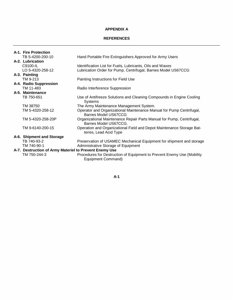
APPENDIX A
REFERENCES
A-1. Fire ProtectionTB 5-4200-200-10 Hand Portable Fire Extinguishers Approved for Army Users
A-2. LubricationC9100-IL Identification List for Fuels, Lubricants, Oils and WaxesLO 5-4320-258-12 Lubrication Order for Pump, Centrifugal, Barnes Model US67CCG
A-3. PaintingTM 9-213 Painting Instructions for Field Use
A-4. Radio SuppressionTM 11-483 Radio Interference Suppression
A-5. MaintenanceTB 750-651 Use of Antifreeze Solutions and Cleaning Compounds in Engine Cooling
SystemsTM 38750 The Army Maintenance Management System.TM 5-4320-258-12 Operator and Organizational Maintenance Manual for Pump Centrifugal,
Barnes Model US67CCGTM 5-4320-258-20P Organizational Maintenance Repair Parts Manual for Pump, Centrifugal,
Barnes Model US67CCG.TM 9-6140-200-15 Operation and Organizational Field and Depot Maintenance Storage Bat-
teries, Lead Acid TypeA-6. Shipment and Storage
TB 740-93-2 Preservation of USAMEC Mechanical Equipment for shipment and storageTM 740-90-1 Administrative Storage of Equipment
A-7. Destruction of Army Materiel to Prevent Enemy UseTM 750-244-3 Procedures for Destruction of Equipment to Prevent Enemy Use (Mobility
Equipment Command)
A-1

APPENDIX B
MAINTENANCE ALLOCATION CHART
Section I. INTRODUCTION
B-1. Generala. This section provides a general explanation of
all maintenance an repair functions authorized atvarious maintenance levels.
b. Section II designates overall responsibility forthe performance of maintenance functions on theidentified end item or component. The implementationof the maintenance functions upon the end item orcomponent will be consistent with the assignedmaintenance functions.
c. Section III contains supplemental instructions,explanatory notes and/or illustrations required for aparticular maintenance function.
B-2. Explanation of Columns in Section II
a. Group Number, Column (1). The assemblygroup is a numerical group assigned to each assemblyin a top down breakdown sequence. The applicableassembly groups are listed on the MAC in disassemblysequence beginning with the first assembly removed ina top down disassembly sequence.
b. Assembly Group, Column (2). This columncontains a brief description of the components of eachassembly group.
c. Maintenance Functions, Column. (3). Thiscolumn lists the various maintenance functions (Athrough K) and indicates the lowest maintenancecategory authorized to perform these functions. Thesymbol designations for the various maintenancecategories are as follows:
C-Operator or crewO-Organizational maintenanceF-Direct support maintenanceH-General support maintenanceD-Depot maintenance
The maintenance functions are defined as follows:
A-Inspect: To determine serviceability of an itemby comparing its physical, mechanical, and electricalcharacteristics with established standards.
B-Test: To verify serviceability and to detectelectrical or mechanical failure by use of test equipment.
C-Service: To clean, to preserve, to charge, andto add fuel, lubricants, cooling agents, and air. If it isdesired that elements, such as painting and lubricating,be defined separately, they may be so listed.
D-Adjust: To rectify to the extent necessary tobring into proper operating range.
E-Aline: To adjust specified variable elements ofan item to bring to optimum performance.
F-Calibrate: To determine the corrections to bemade in the readings of instruments or test equipmentused in precise measurement. Consists of thecomparison of two instruments, one of which is acertified standard of known accuracy, to detect andadjust any discrepancy in the accuracy of the instrumentbeing compared with the certified standard.
G-Install: To set up for use in an operationalenvironment such as an emplacement, site, or vehicle.
H-Replace: To replace unserviceable items withserviceable like items.
I-Repair: Those maintenance operationsnecessary to restore an item to serviceable conditionthrough correction of material damage or a specificfailure. Repair may be accomplished at each categoryof maintenance.
J-Overhaul: Normally, the highest degree ofmaintenance performed by the Army in order tominimize time work in process is consistent with qualityand economy of operation. It consists of thatmaintenance necessary to restore an item to completelyserviceable condition as prescribed by maintenancestandards in technical publications for each item ofequipment. Overhaul normally does not return an itemto like new, zero mileage, or zero hour condition.
K-Rebuild: The highest degree of materielmaintenance. It consists of restoring equipment asnearly as possible to new condition in accord-
B-1

ance with original manufacturing standards. Rebuild isperformed only when required by operationalconsiderations or other paramount factors and then onlyat the depot maintenance category. Rebuild reduces tozero the hours or miles the equipment, or componentthereof, has been in use.
d. Tools and Equipment, Column (4). This columnis provided for referencing by code the special tools andtest equipment, (see III) required to perform themaintenance functions (sec II).
e. Remarks, Column (5). This column is pro-
vided for referencing by code the remarks (sec IV)pertinent to the maintenance functions.
B-4. Explanation of Columns in Section III,
a. Reference Code. This column consists of twoletters separated by a dash, both of which arereferences to Section II. The first letter referencescolumn (5) and the second letter references amaintenance function, column (3), A through K.
b. Remarks. This column lists informationpertinent to the maintenance function being performed,as indicated on the MAC, Section II.
B-2

Section II. MAINTENANCE ALLOCATION CHART
B-3
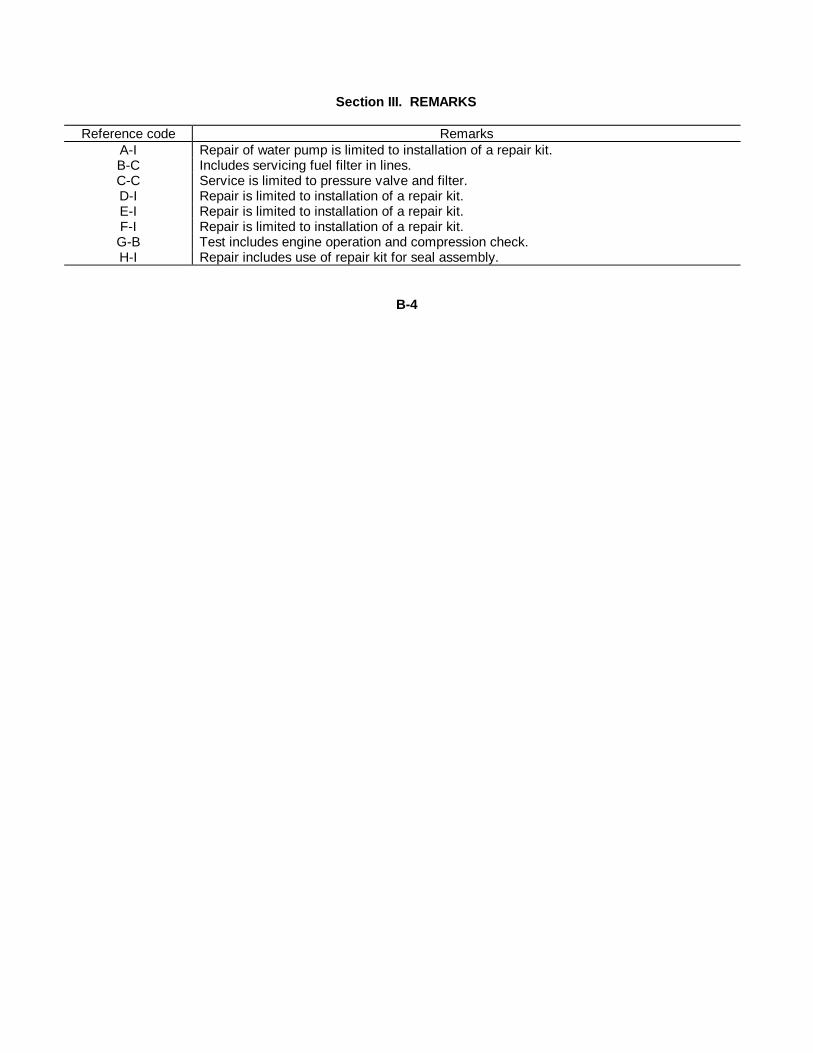
Section III. REMARKS
Reference code RemarksA-I Repair of water pump is limited to installation of a repair kit.B-C Includes servicing fuel filter in lines.C-C Service is limited to pressure valve and filter.D-I Repair is limited to installation of a repair kit.E-I Repair is limited to installation of a repair kit.F-I Repair is limited to installation of a repair kit.G-B Test includes engine operation and compression check.H-I Repair includes use of repair kit for seal assembly.
B-4

APPENDIX C
BASIC ISSUE ITEMS LIST
SECTION I. INTRODCUTION
C-1. ScopeThis appendix lists items which accompany
the pump or are required for installation, operation,or operator's maintenance. Repair Parts andSpecial Tools assigned maintenance code "C" inthe organizational portion of the MaintenanceRepair Parts and Special Tools List Manuals, maybe stocked at the operator level of maintenancewhen authorized by the Unit Commander.
C-2. GeneralThis Basic Issue Items List is divided into the
following sections:
a. Basic Issue Items-Section II. A list of itemswhich accompany the pump and are required bythe crew/operator for installation, operation, ormaintenance.
b. Maintenance and Operating Supplies-Section III. A listing of maintenance and operatingsupplies required for initial operation.
C-3. Explanation of Columns
The following provides an explanation ofcolumns in the tabular list of Basic Issue Items,Section II.
a. Source, Maintenance, and RecoverabilityCodes (SMR):
(1) Source code indicates the source forthe listed item. Source codes are:
Code Explanation
P Repair parts, Special Tools and Test Equipment supplied from the GSA/DSA, or Army supply system and authorized for use at indicated maintenance categories.
P2 Repair parts, Special Tools and Test Equipment which are procured and stocked for insurance purposes because the combat or military essentially of the end item dictates that a minimum quantity be available in the supply system.
M Repair parts, Special Tools and Test Equipment
Code Explanation
which are not procured or stocked, assuch, in the supply system but are to bemanufactured at indicated maintenancelevels.
A Assemblies which are not procured or stocked as such, but are made up of two or more units. Such component units carry individual stock numbers and descriptions, are procured and stocked separately and can be assembled to form the required assembly at indicated maintenance categories.
X Parts and assemblies that are not procured or stocked because the failure rate is normally below that of the applicable end item or component. The failure of such
part of assembly should result in retirement of the end item from the supply system.
X1 Repair parts which are not procured or stocked. The requirement for such items will be filled by use of the next higher assembly or component.
X2 Repair parts, Special Tools and Test Equipment which are not stocked and have no foreseen mortality. The indicated maintenance category requiring such repair parts will attempt to obtain the parts through cannibalization or salvage, if not obtainable through cannibalization or salvage, the item may be requisitioned with exception data, from the end item manager, for immediate use.
G Major assemblies that are procured with PEMA funds for initial issue only as exchange assemblies at DSU and GSU level. These assemblies will not be stocked above DS and GS level or returned to depot supply level.
Note. Cannibalization or salvage may be used asa source of supply for any items source coded aboveexcept those coded X1 and aircraft support items asrestricted by AR 700-42.
(2) Maintenance code indicates the lowestcategory of maintenance authorized to install the listeditem. The maintenance level code is:Code Explanation
C -----------------------Crew/Operator(3) Recoverability code indicates whether
unserviceable items should be returned for recovery orsalvage. Items not coded are nonrecoverable.Recoverability codes are:
C-1

Code Explanation
R Applied to repair parts, (assemblies and components) special tools and test equipment which are considered economically reparable at direct and general support maintenance levels. When the item is no longer economically reparable, it is normally disposed of at the GS level. When supply considerations dictate, some of these repair parts may be listed for automatic return to supply for depot level repair as set forth in AR 71040. When so listed, they will be replaced by supply on an exchange basis.
S Repair parts, special tools, test equipment and assemblies which are economically reparable at DSU and GSU activities and which normally are furnished by supply on an exchange basis. When items are determined by a GSU to be uneconomically reparable, they will be evacuated to a depot for evaluation and analysis before final disposition.
T High dollar value recoverable repair parts, special tools and test equipment which are subject to special handling and are issued on an exchange basis. Such items will be evacuated to the depot for overhaul or final disposition. Communication-Electronics and Missile Support items will be repaired/overhauled only at depots.
U Repair parts, special tools and test equipment specifically selected for salvage by reclamation units because of precious metal content, critical materials, high dollar value or reusable casings or castings.
b. Federal Stock Number. This columnindicates the Federal stock number assigned to theitem and will be used for requisitioning purposes.
c. Description. This column indicates theFederal item name and any additional descriptionof the item required. The abbreviation "w/e", whenused as a part of the nomenclature, indicates theFederal stock number, includes all armament,equipment, accessories, and repair parts issuedwith the item. A part number or other referencenumber is followed by the applicable five-digitFederal supply code for manufacturers inparenthesis. The usable on codes indicate differentmodel and serial number application. Repair partsquantities included in kits, sets, and assemblies areshown in front of the repair part name.
d. Unit of Measure (U/M). A two-characteralphabetic abbreviation indicating the amount or
quantity of the item upon which the allowances arebased, e.g., ft, ea, pr, etc.
e. Quantity Incorporated in Unit. This columnf indicates the quantity of the item used in the\parassembly group. A "V" appearing in thiscolumn in lieu of a quantity indicates that a definitequantity cannot be indicated (e.g. shims, spacers,etc.).
f. Quantity Furnished With Equipment. Thiscolumn indicates the quantity of an item furnishedwith the equipment.
g. Illustration. This column is divided asfollows:
(1) Figure number. Indicates the figurenumber of the illustration in which the item isshown.
(2) Item number. Indicates the calloutnumber used to reference the item in theillustration.
C-4. Explanation of Columns in the TabularList of Maintenance and Operating Supplies-Section III
a. Component Application. This columnidentifies the component application of eachmaintenance or operating supply item.
b. Federal Stock Number. This columnindi\parcates the Federal stock number assigned tothe item and will be used for requisitioningpurposes.
c. Description. This column indicates theitem name and brief description.
d. Quantity Required for Initial Operation.This column indicates the quantity of eachmaintenance or operating supply item required forinitial Operation of the equipment.
e. Quantity Required for Eight Hours Opera-tion. This column indicates the estimatedquantities required for an average 8 hours ofoperation.
f. Notes. This column indicates informativenotes keyed to data appearing in a precedingcolumn.
C-2

Section II. BASIC ISSUE ITEMS
(1) (2) (3) (4) (5) (6) (7)Unit Qty Qty Illustration
SMR Federal stock Description of inc furn (A) (B)Code number meas in with Fig Item
Ref No. & mfr code Usable on code unit equip No. No.PC 7510-889-3494 BINDER, Looseleaf ea 1PC 7520-559-9618 CABLE, Operator and maintenance publications ea 1
ARMY TECHNICAL MANUAL TM 5-4320-258-12 1ARMY LUBRICATION ORDER LO 6-4320-258-12 1
Section III. MAINTENANCE AND OPERATING SUPPLIES
(1) (2) (3) (4) (5) (6)Quantity Quantity
Component Federal required requiredapplication stock number Description F/initial F/8 hours Notes
operation operationCRANKCASEOIL, ENGINE (1) See C9100-IL for additional requisitioning data
9150-246-7923(1) OE 30, 5 gal pail 5½ qts (2)9150-242-7603(1) OES, 5 gal pail (3)
GREASE CUPS GREASE, AUTO & ARTY (2) Crakcase capacity9150-190-0904(1) GAA 1 lb can
ENGINE GASOLINE, BULK (3) Use OES in temperatures below O0F9130-160-1818(1)
C-3

INDEX
Paragraph Page
AAdjustment:
Belt, fan ................................ ................................ ........................... 4-30a 4-20Carburetor . ................................ ................................ ...................... 4-24a 4-15Governor ................................ ................................ .......................... 4-25a 4-16Magneto ................................ ................................ ........................... 4-34b 4-24Points, breaker ................................. ................................ ................ 4-34b 4-24Regulator ................................ ................................ .......................... 4-38a 4-36
Administrative storage ................................ ................................ ............ 1-3 1-1Air cleaner and piping:
Cleaning ................................ ................................ .......................... 4-18c 4-8Description ................................ ................................ ....................... 4-17a 4-7Disassembly ................................ ................................ ..................... 4-18b 4-8Inspection ................................ ................................ ........................ 4-18c 4-8Installation ................................ ................................ ....................... 4-18d 4-8Removal ................................ ................................ .......................... 4-18b 4-8Service ................................ ................................ ............................ 4-18a 4-7
Alternator:Brush replacement ................................ ................................ ........... 4-37b 4-34Cleaning . ................................ ................................ ......................... 4-37c 4-35Inspection ................................ ................................ ........................ 4-37c 4-36Installation ................................ ................................ ....................... 4-37d 4-36Removal ................................ ................................ .......................... 4-37a 4-34Testing ................................ ................................ ............................ 4-36 4-29
Altitudes, operation at high ................................ ................................ ..... 2-13 2-8B
Basic issue items ................................ ................................ ................... 3-1 3-1Battery charging circuit testing . ................................ .............................. 4-36 4-29Belt, fan:
Adjustment ................................ ................................ ....................... 4-30a 4-20Cleaning 430c................................ ................................ .................. 4-21Inspection ................................ ................................ ....................... 4-30c 4-21Installation . ................................ ................................ ...................... 4-30d 4-22Removal................................ ................................ ........................... 4-30b 4-20
Breaker points, replacing and adjusting .... ................................ .............. 4-34b 4-24Brush replacement:Alternator ... ................................ ................................ ............................ 4-37b 4-34Starter................................ ................................ ................................ ..... 4-41c 4-37
C
Carburetor:Adjustment................................ ................................ ........................ . 4-24a 4-15Cleaning ................................ ................................ ......................... 4-24c 4-16Inspection ................................ ................................ ........................ 4-24c 4-16Installation ................................ ................................ ........................ . 4-24d 4-16Removal ................................ ................................ .......................... 4-24b 4-16
Chart, troubleshooting:Operator/crew ................................ ................................ .................. 3-6 3-2Organizational maintenance ................................ ........................... 4-14 4-5
Checks and services, preventive maintenance ................................ ....... 3-4, 4-12 3-1, 4-4Cleaning:
Air cleaner .. ................................ ................................ ..................... 4-18c 4-8Alternator ................................ ................................ ......................... 4-37c 4-35Belt, fan ................................ ................................ ........................... 4-30c 4-21
I-1
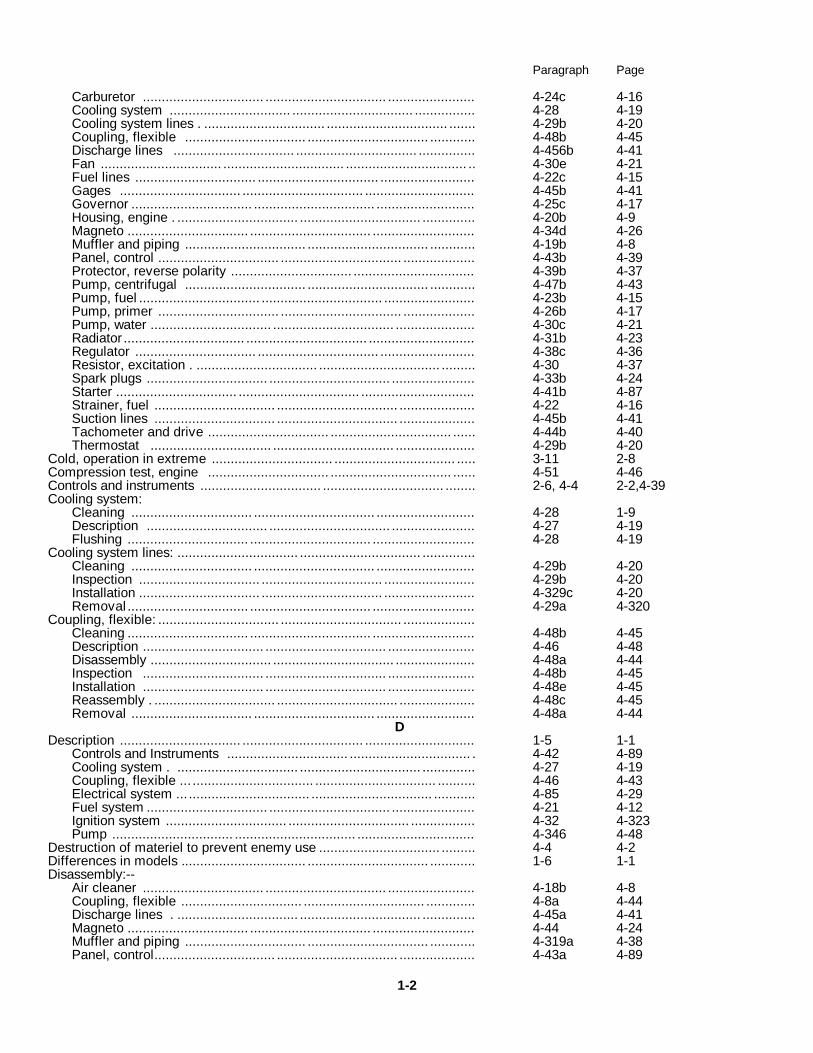
Paragraph Page
Carburetor ................................ ................................ ....................... 4-24c 4-16Cooling system ................................ ................................ ................ 4-28 4-19Cooling system lines . ................................ ................................ ....... 4-29b 4-20Coupling, flexible ................................ ................................ ............ 4-48b 4-45Discharge lines ................................ ................................ ............... 4-456b 4-41Fan ................................ ................................ ................................ .. 4-30e 4-21Fuel lines ................................ ................................ ......................... 4-22c 4-15Gages ................................ ................................ ............................. 4-45b 4-41Governor ................................ ................................ .......................... 4-25c 4-17Housing, engine . ................................ ................................ .............. 4-20b 4-9Magneto ................................ ................................ ........................... 4-34d 4-26Muffler and piping ................................ ................................ ............ 4-19b 4-8Panel, control ................................ ................................ ................... 4-43b 4-39Protector, reverse polarity ................................ ................................ 4-39b 4-37Pump, centrifugal ................................ ................................ ............ 4-47b 4-43Pump, fuel ................................ ................................ ........................ 4-23b 4-15Pump, primer ................................ ................................ ................... 4-26b 4-17Pump, water ................................ ................................ ..................... 4-30c 4-21Radiator ................................ ................................ ............................ 4-31b 4-23Regulator ................................ ................................ ......................... 4-38c 4-36Resistor, excitation . ................................ ................................ ......... 4-30 4-37Spark plugs ................................ ................................ ...................... 4-33b 4-24Starter ................................ ................................ .............................. 4-41b 4-87Strainer, fuel ................................ ................................ .................... 4-22 4-16Suction lines ................................ ................................ .................... 4-45b 4-41Tachometer and drive ................................ ................................ ...... 4-44b 4-40Thermostat ................................ ................................ ..................... 4-29b 4-20
Cold, operation in extreme ................................ ................................ ..... 3-11 2-8Compression test, engine ................................ ................................ ...... 4-51 4-46Controls and instruments ................................ ................................ ........ 2-6, 4-4 2-2,4-39Cooling system:
Cleaning ................................ ................................ .......................... 4-28 1-9Description ................................ ................................ ...................... 4-27 4-19Flushing ................................ ................................ ........................... 4-28 4-19
Cooling system lines: ................................ ................................ ..............Cleaning ................................ ................................ .......................... 4-29b 4-20Inspection ................................ ................................ ........................ 4-29b 4-20Installation ................................ ................................ ........................ 4-329c 4-20Removal................................ ................................ ........................... 4-29a 4-320
Coupling, flexible: ................................ ................................ ...................Cleaning ................................ ................................ ........................... 4-48b 4-45Description ................................ ................................ ....................... 4-46 4-48Disassembly ................................ ................................ ..................... 4-48a 4-44Inspection ................................ ................................ ....................... 4-48b 4-45Installation ................................ ................................ ....................... 4-48e 4-45Reassembly . ................................ ................................ .................... 4-48c 4-45Removal ................................ ................................ .......................... 4-48a 4-44
DDescription ................................ ................................ ............................. 1-5 1-1
Controls and Instruments ................................ ................................ . 4-42 4-89Cooling system . ................................ ................................ .............. 4-27 4-19Coupling, flexible ... ................................ ................................ .......... 4-46 4-43Electrical system ... ................................ ................................ ........... 4-85 4-29Fuel system ................................ ................................ ...................... 4-21 4-12Ignition system ................................ ................................ ................. 4-32 4-323Pump ................................ ................................ ............................... 4-346 4-48
Destruction of materiel to prevent enemy use ................................ ......... 4-4 4-2Differences in models ................................. ................................ ............ 1-6 1-1Disassembly:--
Air cleaner ................................ ................................ ....................... 4-18b 4-8Coupling, flexible ................................ ................................ ............. 4-8a 4-44Discharge lines . ................................ ................................ .............. 4-45a 4-41Magneto ................................ ................................ ........................... 4-44 4-24Muffler and piping ................................ ................................ ............ 4-319a 4-38Panel, control................................ ................................ .................... 4-43a 4-89
1-2

Paragraph Page
Suction lines ................................ ................................ .................... 4-45a 4-41Discharge lines:
Cleaning ................................ ................................ ......................... 4-45b 4-41Disassembly ................................ ................................ .................... 4-45a 4-41Inspection ................................ ................................ ....................... 4-45b 4-41Installation ................................ ................................ ...................... 4-46c 4-41Reassembly ................................ ................................ ..................... 4-45c 4-41Removal ................................ ................................ .......................... 4-45a 4-41
Dismantling for movement ................................ ................................ ..... 2-3 2-2E-
Electrical system description ................................ ................................ .. 4-35 4-29Engine:-
Compression test ................................ ................................ ............ 4-51 4-46General................................. ................................ ............................ 4-49 4-45Lubrication ................................ ................................ ...................... 4-9 4-3Operational test . ................................ ................................ ............ 4-50 4-45
Equipment:Inspecting ................................ ................................ ......................... 2-1 2-1Servicing ................................ ................................ ......................... 2-1 2-1
Errors, reporting of ................................ ................................ ................. 1-4 1-1F
Fan:Cleaning ................................ ................................ .......................... 4-30c 4-21Inspection ................................ ................................ ....................... 4-30c 4-21Installation ................................ ................................ ....................... 4-30d 4-22Removal ................................ ................................ .......................... 4-30b 4-20
Flushing the cooling system ................................ ................................ .. 4-28 4-19Forms and records ................................ ................................ ................. 1-2 1-1Fuel lines:
Cleaning ................................ ................................ .......................... 4-22c 4-15Inspection ................................ ................................ ....................... 4-22c 4-15Reassembly ................................ ................................ ..................... 4-22d 4-15Removal ................................ ................................ .......................... 4-22b 4-13
Fuel system description ................................. ................................ ......... 2-1 4-12G
Gages:Cleaning ................................ ................................ .......................... 4-45b 4-41Inspection ................................ ................................ ........................ 4-46b 4-41Installation . ................................ ................................ ...................... 4-45c 4-41Removal ................................ ................................ .......................... 4-45a 4-41
Governor, engine speed:................................ ................................ .........Adjustment ................................. ................................ ...................... 4-25a 4-16Cleaning ................................ ................................ ......................... 4-25c 4-17Inspection ................................ ................................ ........................ 4-25c 4-17Installation ................................ ................................ ....................... 4-25d 1-7Removal................................ ................................ ........................... 4-25b 4-17
HHeat, operation in extreme ................................ ................................ ..... 2-12 2-8High altitudes, operation in ................................ ................................ .... 2-13 2-8Housing, engine:
Cleaning . ................................ ................................ ......................... 4-20b 4-9Description................................ ................................ ........................ 4-17c 4-7Inspection ................................ ................................ ........................ 4-20b 4-9Installation ................................ ................................ ........................ 4-20 4-9Removal ................................ ................................ .......................... 4-20a 4-9
IIdentification and tabulated data ................................ ............................. 1-7 1-1Ignition system description ................................ ................................ .... 4-32 4-23Inspecting and servicing the equipment ................................ .................. 2-1 2-1Inspection:
Air cleaner ................................ ................................ ........................ 4-18e 4-8Alternator 7 ................................ ................................ ....................... 4-37 4-35
I-3

Paragraph Page
Belt, fan ................................ ................................ .......................... 4-30c 4-21Carburetor ................................ ................................ ....................... 4-24c 4-16Cooling system lines . ................................ ................................ ....... 4-29b 4-20Coupling, flexible ................................ ................................ ............. 4-48b 4-45Discharge lines ................................ ................................ ............... 4-45b 4-41Fan . ................................ ................................ ................................ 4-30c 4-21Fuel lines ................................ ................................ ......................... 4-22c 4-15Gages ................................ ................................ .............................. 4-45b 4-41Governor ................................ ................................ ......................... 4-25c 4-17Housing, engine ................................ ................................ ............... 4-20b 4-9Magneto ................................ ................................ ........................... 4-34d 4-26Muffler and piping ................................ ................................ ........... 4-19b 4-8Panel, control ................................ ................................ .................. 4-43b 4-39Protector, reverse polarity ................................ ................................ 4-39b 4-37Pump, centrifugal ................................ ................................ ............ 4-47b 4-43Pump, fuel ................................ ................................ ........................ 4-23b 4-15Pump, primer ................................ ................................ .................... 4-26b 4-17Pump, water ................................ ................................ ..................... 4-30c 4-21Radiator ................................ ................................ ........................... 4-31b 4-23Regulator ................................ ................................ ......................... 4-83 4-36Resistor, excitation . ................................ ................................ ......... 4-40b 4-37Spark plugs ................................ ................................ ..................... 4-33b 4-24Starter ................................ ................................ ............................. 4-41b 4-37Strainer, fuel . ................................ ................................ ................... 4-22c 4-15Suction lines ................................ ................................ .................... 4-4b 4-41Tachometer and drive ................................. ................................ ..... 4-44b 4-40Thermostat . ................................ ................................ .................... 4-29b 4-20
Installation ................................ ................................ .............................. 2-2 2-1Air cleaner ................................ ................................ ....................... 4-18d 4-8Alternator ................................ ................................ ......................... 4-37d 4-34Belt, fan ................................ ................................ ........................... 4-30d 4-22Carburetor ................................ ................................ ....................... 4-24d 4-16Cooling system lines ................................ ................................ ......... 4-29c 4-20Coupling, flexible................................ ................................ .............. 4-48c 4-45Discharge lines . ................................ ................................ ............... 4-45c 4-41Fan ................................ ................................ ................................ .. 4-30d 4-22Gages ................................ ................................ .............................. 4-45c 4-41Governor ................................ ................................ ......................... 4-25d 4-17Housing, engine ................................ ................................ ............... 4-20c 4-9Magneto ................................ ................................ .......................... . 4-34f 4-28Panel, control ................................... ................................ ................ 4-43c 4-39Protector, reverse polarity .................................. .............................. 4-39c 4-37Pump, centrifugal................................. ................................ ............. 4-47c 4-44Pump, fuel ... ................................ ................................ ................... 4-23c 4-15Pump, primer ................................ ................................ .................. 4-26c 4-19Pump, water ................................ ................................ .................... ., 4-30d 4-22Radiator ................................ ................................ ............................ 4-31c 4-23Regulator ................................ ................................ ......................... 4-38d 4-36Resistor, excitation .. ................................ ................................ ....... 4-40c 4-37Spark plugs ................................ ................................ ...................... 4-33c 4-24Starter ................................... ................................ ........................... 4-41e 4-38Suction lines .. ................................ ................................ ................. 4-45c 4-41Tachometer and drive................................ ................................ ....... 4-44c 4-41Thermostat ................................ ................................ ...................... 4-29c 4-20
Instructions, lubrication ................................ ................................ .......... 3-2 3-1Instruments ................................ ................................ ............................ 2-6, 4-42 2-2, 4-39
Cleaning ................................ ................................ .......................... 4-43b 4-39Disassembly ................................ ................................ ................... 4-43a 4-39Inspection ................................ ................................ ......................... 4-43b 4-39Installation ................................ ................................ ...................... 4-43c 4-39Reassembly ................................ ................................ ..................... 4-43c 4-39Removal ................................ ................................ ......................... 4-43a 4-39
Items, basic issue ................................ ................................ ................... 3-1 3-1L
Lubrication:Engine .. ................................ ................................ ................................ . 4-9 4-3
I-4

Paragraph PageInstructions ................................ ................................ ............................ 3-2 3-1Pump ................................ ................................ ................................ ..... 4-10 4-4
MMagneto:................................ ................................ ................................ .
Adjustment ................................ ................................ ....................... 4-34b 4-24Cleaning ................................ ................................ .......................... 4-34d 4-26Disassembly ................................ ................................ ................... 4-34 4-26Inspection ................................ ................................ ........................ 4-34d 4-26Installation ................................ ................................ ...................... 4-34f 4-28Reassembly ................................ ................................ ..................... 4-34e 4-27Removal ................................ ................................ .......................... 4-34a 4-24
Maintenance: ................................ ................................ ..........................Preventive, checks and services ................................ ...................... 3-4, 4-1 3-1, 4-4Repair parts ................................ ................................ ..................... 4-7 4-2
Models, differences in ................................ ................................ ............ 1-6 1-1Movement:................................ ................................ ..............................
Dismantling for ................................ ................................ ................ 2-3 2-2Reinstallation after ................................ ................................ ............ 2-4 2-2
Mud, operation in ................................ ................................ ................... 2-18 2-9Muffler and piping: ................................ ................................ ..................
Cleaning ................................ ................................ ......................... 4-19b 4-8Description ................................ ................................ ....................... 4-17b 4-7Disassembly ................................ ................................ .................... 4-19a 4-8Inspection ................................ ................................ ........................ 4-19b 4-8Reassembly ................................ ................................ .................... 4-19c 4-9
O
Operation ................................ ................................ .............................. 2-10 2-7In extreme cold ................................ ................................ ............... 2-11 2-8In extreme heat ................................ ................................ ................ 2-12 2-8In high altitudes ................................ ................................ ............... 2-13 2-8In mud ................................ ................................ ............................. 2-18 2-9In salt water areas ................................ ................................ ........... 2-16 2-9In sandy or dusty areas ................................ ................................ ... 2-14 2-9In snow ................................ ................................ ........................... 2-17 2-9Under rainy or humid conditions . ................................ ...................... 2-15 2-9
Operational test, engine ................................ ................................ ......... 4-50 4-5Operator/crew troubleshooting chart ................................ ...................... 3-6 3-2Organizational maintenance troubleshooting chart ................................ . 4-14 4-6Panel, control: ................................ ................................ .........................
Cleaning ................................ ................................ .......................... 4-43b 4-39Disassembly ................................ ................................ .................... 4-43a 4-49Inspection ................................ ................................ ........................ 4-43b 4-89Installation .. ................................ ................................ ..................... 4-43c 4-39Reassembly.. ................................ ................................ ................... 4-43c 4-39Removal ................................ ................................ .......................... 4-43a 4-39
Parts, maintenance repair ................................ ................................ ...... 4-7 4-2Points, breaker, replacing and adjusting ................................ ................. 4-34b 4-24Preventive maintenance checks and services ................................. ....... 3-4, 4-1 3-1, 4-4Protector, reverse polarity: ................................ ................................ ......
Cleaning ................................ ................................ .......................... 4-39b 4-37Inspection . ................................ ................................ ....................... 4-39b 4-87Installation ................................ ................................ ....................... 4-39c 4-37Removal ................................ ................................ .......................... 4-39a 4-37
Pump, centrifugal:Cleaning ................................ ................................ .......................... 4-47b 4-43Description ................................ ................................ ...................... 4-46 4-43Inspection ................................ ................................ ........................ 4-47b 4-48Installation . ................................ ................................ ...................... 4-47c 4-44Removal................................ ................................ ........................... 4-47a 4-43
Pump, fuel:--Cleaning ................................ ................................ .......................... 4-23b 4-15Inspection . ................................ ................................ ....................... 4-23b 4-15Installation ................................ ................................ ...................... 4-23c 4-15Removal ................................ ................................ .......................... 4-23a 4-15
I-5
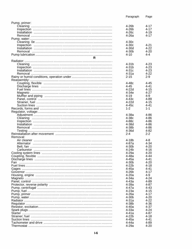
Paragraph Page
Pump, primer:Cleaning ................................ ................................ .......................... 4-26b 4-17Inspection ................................ ................................ ........................ 4-26b 4-17Installation ................................ ................................ ....................... 4-26c 4-19Removal ................................ ................................ .......................... 4-26a 4-17
Pump, water:................................ ................................ ...........................Cleaning 0e ................................ ................................ ..................... 4-30cInspection ................................ ................................ ....................... 4-30c 4-21Installation ................................ ................................ ....................... 4-30d 4-22Removal ................................ ................................ ......................... 4-30b 4-20
Pump lubrication ................................ ................................ ..................... 4-10 4-4R
Radiator: ................................ ................................ ................................ .Cleaning ................................ ................................ .......................... 4-31b 4-23Inspection ................................ ................................ ........................ 4-31b 4-23Installation ................................ ................................ ....................... 4-31c 4-23Removal ................................ ................................ .......................... 4-31a 4-22
Rainy or humid conditions, operation under ................................ ............. 2-15 2-9Reassembly: ................................ ................................ ...........................
Coupling, flexible ................................ ................................ ............ 4-48c 4-45Discharge lines ................................ ................................ ............... 4-45 4-41Fuel lines ................................ ................................ ......................... 4-22d 4-15Magneto ................................ ................................ ........................... 4-34e 4-27Muffler and piping ................................ ................................ ........... 4-19 4-9Panel, control ................................ ................................ .................. 4-43c 4-89Strainer, fuel ................................ ................................ .................... 4-22d 4-15Suction lines ................................ ................................ .................... 4-45c 4-41
Records, forms and ................................ ................................ ................ 1-2 1-1Regulator, voltage:................................ ................................ ..................
Adjustment ................................ ................................ ....................... 4-38a 4-86Cleaning ................................ ................................ ......................... 4-38c 4-86Inspection ................................ ................................ ........................ 4-88c 4-86Installation ................................ ................................ ....................... 4-38d 4-86Removal ................................ ................................ ......................... 4-38b 4-86Testing ................................ ................................ ............................. 4-36d 4-82
Reinstallation after movement ................................ ............................... 2-4 2-2Removal:
Air cleaner ................................ ................................ ....................... 4-18b 4-8Alternator ................................ ................................ ........................ 4-87a 4-34Belt, fan ................................ ................................ ........................... 4-30b 4-20Carburetor ................................ ................................ ....................... 4-24b 4-16
Cooling system lines ................................ ................................ .............. 4-29a 4-20Coupling, flexible ................................ ................................ ................... 4-48a 4-44Discharge lines ................................ ................................ ...................... 4-45a 4-41Fan ................................ ................................ ................................ ....... 4-30b 4-20Fuel lines ................................ ................................ ................................ 4-22b 4-18Gages ................................ ................................ ................................ .... 4-45a 4-41Governor ................................ ................................ ................................ 4-26b 4-17Housing, engine ................................ ................................ ..................... 4-20a 4-9Magneto ................................ ................................ ................................ . 4-34a 4-24Panel, control ................................ ................................ ......................... 4-43a 4-89Protector, reverse polarity ................................ ................................ ...... 4-39a 4-87Pump, centrifugal ................................ ................................ ................... 4-47a 4-43Pump, fuel ................................ ................................ .............................. 4-23a 4-15Pump, primer ................................ ................................ .......................... 4-26a 4-17Pump, water................................ ................................ ............................ 4-30b 4-20Radiator ................................ ................................ ................................ .. 4-31a 4-22Regulator ................................ ................................ ................................ 4-38b 4-36Resistor, excitation................................ ................................ .................. 4-40a 4-37Spark plugs ................................ ................................ ............................. 4-33a 4-24Starter ................................ ................................ ................................ .... 4-41a 4-87Strainer; fuel ................................ ................................ .......................... 4-22b 4-18Suction lines ................................ ................................ .......................... 4-45a 4-41Tachometer and drive ................................ ................................ ............ 4-44a 4-89Thermostat ................................ ................................ ............................. 4-29a 4-20
I-6

Paragraph Page
Repair parts, maintenance ................................ ................................ ..... 4-7 4-2Replacement:................................ ................................ ..........................
Brushes, alternator ................................ ................................ ........... 4-37b 4-34Brushes, starter ................................ ................................ ................ 4-41 4-87Points, breaker ................................ ................................ ................. 4-34b 4-24
Reporting of errors ................................ ................................ ................ 1-4 1-1Resistor, excitation:
Cleaning ................................ ................................ .......................... 4-40b 4-87Inspection ................................ ................................ ........................ 4-40b 4-37Installation ................................ ................................ ....................... 4-40c 4-87Removal ................................ ................................ ......................... 4-40a 4-487
SSalt water areas, operation in . ................................ ................................ 2-16 2-9Sandy or dusty areas, operation in . ................................ ........................ 2-14 2-9Scope ................................ ................................ ................................ .... 1-1 1-1Service:
Air cleaner ................................ ................................ ...................... 4-18a 4-7Strainer, fuel ................................ ................................ .................... 4-22 4-13
Services, preventive maintenance checks and ................................ ...... 3-4,4-12 3-1, 4-4Servicing the equipment ................................ ................................ ......... 2-4-1, 4-2 2-1, 4-1Snow, operation in ................................ ................................ ................ 2-17 2-9Spark plugs:
Cleaning ................................ ................................ .......................... 4-33b 4-24Inspection ................................ ................................ ........................ 4-33b 4-24Installation ................................ ................................ ....................... 4-33c 4-24Removal ................................ ................................ .......................... 4-438a 2-44
Special tools and equipment ................................ ................................ .. 4-6 4-2Starter, engine:
Brush replacement ................................ ................................ ........... 4-41c 4-37Cleaning ................................ ................................ ........................... 4-41b 4-37Inspection ................................ ................................ ....................... 4-41b 4-37Installation ................................ ................................ ....................... 4-441e 4-38Removal ................................ ................................ .......................... 4-41a 4-37
Testing ................................ ................................ ................................ .. 4-41d 4-38Starting ................................ ................................ ................................ . 2-8 2-7Stopping ................................ ................................ ................................ . 2-9 2-7Storage, administrative ................................ ................................ .......... 1-3 1-1Strainer, fuel:
Cleaning ................................ ................................ .......................... 4-22c 4-15Inspection ................................ ................................ ........................ 4-22c 4-15Reassembly ................................ ................................ ..................... 4-22d 4-15Removal ................................ ................................ .......................... 4-22b 4-13Service ................................ ................................ ............................ 4-22a 4-13
Suction lines:-Cleaning ................................ ................................ .......................... 4-45b 4-41Disassembly ................................ ................................ .................... 4-45a 4-41Inspection . ................................ ................................ ....................... 4-45b 4-41Installation ................................ ................................ ....................... 4-45c 4-41Reassembly ................................ ................................ .................... 4-45c 4-41Removal ................................ ................................ ......................... 4-45a 4-41
Suppression:Components replacement methods to attain . ................................ ......... 4-15, 4-16 4-7
TTabulated data, identification and ................................ .......................... 1-7 1-1Tachometer and drive:
Cleaning ................................ ................................ ......................... 4-44b 4-40Inspection ................................ ................................ ........................ 4-44b 4-40Installation ................................ ................................ ....................... 4-44c 4-41Removal ................................ ................................ .......................... 4-44a 4-39
Testing:Alternator ................................ ................................ ......................... 4-36 4-29Charging circuit ................................ ................................ ................. 4-36 4-29Engine compression ................................ ................................ ......... 4-51 4-46Engine operation ................................ ................................ .............. 5-40 4-45
I-7

Paragraph Page
Regulator ................................ ................................ .......................... 4-36d 4-82Starter ................................ ................................ .............................. 4-41d 4-88
Thermostat:Cleaning ................................ ................................ ........................... 4-29b 4-20Inspection ................................ ................................ ......................... 4-29b 4-20Installation ................................ ................................ ........................ 4-29c 4-20Removal ................................ ................................ .......................... 4-29a 4-20
Tools and equipment ................................ ................................ .............. 4-5 4-2Troubleshooting chart:
Operator/crew ................................ ................................ .................. 3-6 3-2Organizational maintenance ................................ ............................ 414 4-6
U
Usual conditions, operation under . ................................ ........................ 2-10 2-7
I-8

By Order of the Secretary of the Army:
W. C. WESTMORELAND,General, United States Army,
Official: Chief of Staff.VERNE L. BOWERS,Major General, United States Army,The Adjutant General.
Distribution:To be distributed in accordance with DA Form 1225, (qty rqr block No. 153) operator maintenance requirements
for Petroleum Distribution.
* U.S. GOVERNMENT PRINTING OFFICE: 1971-769-157/56021


The Metric System and Equivalents
Linear Measure Liquid Measure
1 centiliter = 10 milliters = .34 fl. ounce1 centimeter = 10 millimeters = .39 inch 1 deciliter = 10 centiliters = 3.38 fl. ounces1 decimeter = 10 centimeters = 3.94 inches 1 liter = 10 deciliters = 33.81 fl. ounces1 meter = 10 decimeters = 39.37 inches 1 dekaliter = 10 liters = 2.64 gallons1 dekameter = 10 meters = 32.8 feet 1 hectoliter = 10 dekaliters = 26.42 gallons1 hectometer = 10 dekameters = 328.08 feet 1 kiloliter = 10 hectoliters = 264.18 gallons1 kilometer = 10 hectometers = 3,280.8 feet
Square MeasureWeights
1 sq. centimeter = 100 sq. millimeters = .155 sq. inch1 centigram = 10 milligrams = .15 grain 1 sq. decimeter = 100 sq. centimeters = 15.5 sq. inches1 decigram = 10 centigrams = 1.54 grains 1 sq. meter (centare) = 100 sq. decimeters = 10.76 sq. feet1 gram = 10 decigram = .035 ounce 1 sq. dekameter (are) = 100 sq. meters = 1,076.4 sq. feet1 decagram = 10 grams = .35 ounce 1 sq. hectometer (hectare) = 100 sq. dekameters = 2.47 acres1 hectogram = 10 decagrams = 3.52 ounces 1 sq. kilometer = 100 sq. hectometers = .386 sq. mile1 kilogram = 10 hectograms = 2.2 pounds1 quintal = 100 kilograms = 220.46 pounds Cubic Measure1 metric ton = 10 quintals = 1.1 short tons
1 cu. centimeter = 1000 cu. millimeters = .06 cu. inch1 cu. decimeter = 1000 cu. centimeters = 61.02 cu. inches1 cu. meter = 1000 cu. decimeters = 35.31 cu. feet
Approximate Conversion Factors
To change To Multiply by To change To Multiply by
inches centimeters 2.540 ounce-inches Newton-meters .007062feet meters .305 centimeters inches .394yards meters .914 meters feet 3.280miles kilometers 1.609 meters yards 1.094square inches square centimeters 6.451 kilometers miles .621square feet square meters .093 square centimeters square inches .155square yards square meters .836 square meters square feet 10.764square miles square kilometers 2.590 square meters square yards 1.196acres square hectometers .405 square kilometers square miles .386cubic feet cubic meters .028 square hectometers acres 2.471cubic yards cubic meters .765 cubic meters cubic feet 35.315fluid ounces milliliters 29,573 cubic meters cubic yards 1.308pints liters .473 milliliters fluid ounces .034quarts liters .946 liters pints 2.113gallons liters 3.785 liters quarts 1.057ounces grams 28.349 liters gallons .264pounds kilograms .454 grams ounces .035short tons metric tons .907 kilograms pounds 2.205pound-feet Newton-meters 1.356 metric tons short tons 1.102pound-inches Newton-meters .11296
Temperature (Exact)
°F Fahrenheit 5/9 (after Celsius °Ctemperature subtracting 32) temperature

PIN: 008487-000

This fine document...
Was brought to you by me:
Liberated Manuals -- free army and government manuals
Why do I do it? I am tired of sleazy CD-ROM sellers, who take publicly available information, slap “watermarks” and other junk on it, and sell it. Those masters of search engine manipulation make sure that their sites that sell free information, come up first in search engines. They did not create it... They did not even scan it... Why should they get your money? Why are not letting you give those free manuals to your friends?
I am setting this document FREE. This document was made by the US Government and is NOT protected by Copyright. Feel free to share, republish, sell and so on.
I am not asking you for donations, fees or handouts. If you can, please provide a link to liberatedmanuals.com, so that free manuals come up first in search engines:
<A HREF=http://www.liberatedmanuals.com/>Free Military and Government Manuals</A>
– SincerelyIgor Chudovhttp://igor.chudov.com/
– Chicago Machinery Movers