*tm 55-1905-223-24-11
TRANSCRIPT

*TM 55-1905-223-24-11
TECHNICAL MANUAL
UNIT, INTERMEDIATE DIRECT SUPPORT
AND INTERMEDIATE GENERAL SUPPORT
MAINTENANCE INSTRUCTIONS
MARINE SANITATION DEVICE (MSD)
FOR LANDING CRAFT UTILITY (LCU)
NSN 1905-01-154-1191 *Supersedes TM 55-1905-223-24-11, 17 January 1989, including all changes.
DISTRIBUTION STATEMENT A: Approved for public release, distribution is unlimited.
HEADQUARTERS, DEPARTMENT OF THE ARMY
FEBRUARY 2008

TM 55-1905-223-24-11
a
WARNING SUMMARY The ORCA IIA Marine Sanitation Device (MSD) receives, treats, and discharges processed sewage (blackwater – B/W or graywater G/W) waste overboard (when permitted). BLACKWATER - waste of human origin from water closets and urinals that is transported by the ship sewage system. GRAYWATER - discarded water from deck drains, lavatories, showers, dishwashers, laundries, and garbage grinders as well as discarded water from shipboard medical facilities. Graywater does not include industrial waste, infectious waste, and/or human body waste. Personnel must, at all times, observe all safety regulations while performing maintenance or repairs. Every practical safety feature has been incorporated into the design and manufacture of this equipment, however, personnel must be aware of the following potential hazards:
MODIFICATION HAZARD Unauthorized modifications, alterations or installations of or to this equipment are prohibited and are in violation of AR 750-10. Any such unauthorized modifications, alterations or installations could result in death, injury or damage to the equipment.
MOVING MACHINERY HAZARDS
Be very careful when operating or working near moving machinery. Running engines, rotating shafts and other moving machinery parts could cause personal injury or death. Before maintenance is performed on motor driven equipment, the main circuit breaker should be de-energized and labeled “OUT OF SERVICE.” Only authorized maintenance personnel should make repairs to this equipment.
GAS HAZARDS A serious potential hazard associated with sewage systems is hydrogen sulfide (H2S). It is a colorless, flammable, toxic gas with a characteristic smell of rotten eggs at low concentrations. However the sense of smell is lost after 2-15 minutes of exposure, making it impossible to smell dangerous concentrations. The permissible exposure limit (PEL) for H2S is 10 parts of H2S for every million parts of air (commonly expressed as 10 ppm H2S). The IDLH (Immediately Dangerous to Life or Health) limit is 100 ppm H2S. In addition when H2S burns, it produces another very toxic gas, sulfur dioxide (SO2). For additional information, refer to Naval Ships Technical Manual (NSTM) Chapter 593, POLLUTION CONTROL, S9086-T8-STM-010. When removing access covers, fresh air from a known outside source must be supplied to the surrounding area. Only after this fresh air has been supplied for proper tank ventilation should personnel open the tank. Under no circumstances should any person service a tank without a second person, capable of rendering aid, standing by. If an extended period of time for tank repair is anticipated, personnel should utilize the proper respiratory equipment. Immediately Dangerous To Life Or Health (IDLH) is a classification assigned by the U.S. Navy Gas-Free Engineering Program (Naval Ships’ Technical Manual (NSTM) CHAPTER 074, VOLUME 3 - GAS FREE ENGINEERING S9086-CH-STM-030) to a confined space (such as sewage holding tanks or sewage system piping) in which the atmosphere meets one or more of the following conditions: flammable vapors at a concentration of 10 percent or greater of the lower explosive limit (LEL); an oxygen content of less than 19.5% or greater than 22%; the presence of toxicants above IDLH exposure limits given in Appendix G of NSTM Chapter 074, Volume 3. Entry into IDLH spaces is authorized only under emergency conditions and only the Commanding Officer can authorize opening and entry into IDLH spaces. Additional information concerning hydrogen sulfide and sewage tank entry is provided in NSTM Chapter 593, S9086-T8-STM-010 and NSTM CHAPTER 074, VOLUME 3, S9086-CH-STM-030.

TM 55-1905-223-24-11
b
SAFETY SUMMARY - Continued
CHEMICAL HAZARDS The ORCA IIA MSD requires a constant supply of hypochlorite solution (common household bleach). Containers for the solution must be stored in a six inch bed of sand, located in a well ventilated, dark, and dry area. When handling containers, take extreme care to avoid hypochlorite solution contact with the skin, excessive inhalation of the vapors, or splashing in eyes. In case of an accident, flush the affected areas with water IMMEDIATELY. An Emergency Eye Wash Station must be located in the bleach storage area.
DISEASE HAZARDS Good personal hygiene habits by those operating and servicing the MSD are imperative. Washing of hands with hot, potable water and disinfectant soap should be accomplished after coming in contact with sewage or any contaminated equipment. Personnel shall not be allowed to eat, smoke, or drink, in the MSD pump room. Personnel with skin abrasions, punctures, or any other wounds shall not be allowed to service MSD equipment. In order to minimize the risks of health and sanitation hazards associated with the MSD, personnel shall follow sanitary and hygienic practices contained in section 4 of NSTM Chapter 593, S9086–T8–STM-010. When performing maintenance, which requires disassembly of sewage equipment or when contact with sewage is possible, personnel protective equipment (PPE) specified in section 4 of NSTM Chapter 593, S9086–T8–STM-010 shall be donned.
ELECTRICAL HAZARDS Respect all circuits. Precautions set forth in Naval Ship’s Technical Manual (NSTM), Chapters 300, 302, 310, and 320, shall be observed with respect to electrical equipment and circuits. Special precautionary measures are essential to prevent applying power to the system/equipment at any time maintenance work is in progress. Disconnect power and tag the circuit to warn of a potentially dangerous situation. Use a multimeter to ensure all electrical circuits are de-energized before touching any part of the circuit. Before working on electrical system/equipment, check with multimeter to ensure that system is not energized. Circuits not known to be dead must be considered live and dangerous at all times. The voltages used to operate this equipment are high enough to cause severe injury or death. When working near electricity, do not use metal rules, flashlights, metallic pencils, or any other objects having exposed conducting material. Troubleshooting procedures frequently require that checks be made while the power is on. Use extreme care to prevent contact with live circuit parts. Touching these parts could result in electrical shock. Be sure to de-energize all equipment before connecting or disconnecting meters or test leads. When connecting a meter to terminals for measurement, use a range higher than the expected voltage.
DO NOT REPAIR OR ADJUST ALONE Under no circumstances should repair or adjustment of energized equipment be attempted alone. The immediate presence of someone capable of rendering aid is required. Before making adjustments, be sure to protect against grounding. If possible, adjustments should be made with one hand, with the other hand free and clear of equipment. Even when power has been removed from equipment circuits, dangerous potentials may still exist due to retention of charges by capacitors. Circuits must be grounded and all capacitors discharged prior to attempting repairs.
TEST EQUIPMENT Make certain test equipment is in good condition. If a test meter must be held, ground the case of the meter before starting measurements. Do not touch live equipment or personnel working on live equipment while holding a test meter. Some types of measuring devices should not be grounded; such devices should not be held when taking measurements.
INTERLOCKS Interlocks are provided for safety of personnel and equipment and should be used only for the purpose intended. They should not be battle-shorted or otherwise modified except by authorized maintenance personnel. Do not depend solely upon interlocks for protection. Whenever possible, disconnect power at power distribution source.
For Artificial Respiration, refer to FM 4-25.11.
*TM 55-1905-223-24-11
A/(B blank)
LIST OF EFFECTIVE PAGES NOTE: *Supersedes TM 55-1905-223-24-11, 17 January 1989, including all changes.
Date of issue for revision is: 08 February 2008.
TOTAL NUMBER OF PAGES IS 162 CONSISTING OF THE FOLLOWING: Page *Change No. No.
Page *Change No. No.
Cover.................................................................0 a and b...............................................................0 i and ii ................................................................0 1-1 through 1-12 ................................................0 2-1 through 2-89/(2-90 blank) ...........................0 3-1 through 3-22.................................................0 4-1/(4-2 blank) ...................................................0 *Zero in this column indicates an original page.
A-1/(A-2 blank) ................................................ 0 B-1 through B-5/(B-6 blank) ............................. 0 C-1 and C-2 ..................................................... 0 D-1 and D-2 ...................................................... 0 Glossary-1 and Glossary-2............................... 0 Index-1 and Index-2.............................................. 0 DA 2028 .......................................................... 0 Metric Chart/PIN ............................................. 0

*TM 55-1905-223-24-11
i
TECHNICAL MANUAL HEADQUARTERS DEPARTMENT OF THE ARMY WWASHINGTON, D.C., 08 February 2008
UNIT, INTERMEDIATE DIRECT SUPPORT AND INTERMEDIATE GENERAL SUPPORT
MAINTENANCE INSTRUCTIONS
MARINE SANITATION DEVICE (MSD) FOR
LANDING CRAFT UTILITY (LCU) NSN 1905-01-154-1191
REPORTING ERRORS AND RECOMMENDING IMPROVEMENTS
You can help improve this publication. If you find any mistakes or if you know of a way to improve the procedures, please let us know. Submit your DA Form 2028 (Recommended Changes to Equipment Technical Publications) through the Internet, on the Army Electronic Product Support (AEPS) website. The Internet address is https://aeps.ria.army.mil. The DA Form 2028 is located under the Public Applications section in the AEPS Public Home Page. Fill out the form and click on SUBMIT. Using this form on the AEPS will enable us to respond quicker to your comments and better manage the DA Form 2028 program. You may also mail, fax or e-mail your letter or DA Form 2028 direct to: TACOM Life Cycle Management Command, ATTN: AMSTA-LC-LMPP/TECH PUBS, 1 Rock Island Arsenal, Rock Island, IL 61299-7630. The e-mail address is [email protected]. The fax number is DSN 793-0726 or Commercial (309) 782-0726.
DISTRIBUTION STATEMENT A: Approved for public release; distribution is unlimited.
TABLE OF CONTENTS
PAGE CHAPTER 1 INTRODUCTION.................................................................................................... 1-1 Section I General Information ............................................................................................... 1-1 Section II Equipment Description and Data ........................................................................... 1-2 Section III Principles of Operation........................................................................................... 1-5 CHAPTER 2 UNIT MAINTENANCE INSTRUCTIONS................................................................ 2-1 Section I Repair Parts; Special Tools; Test, Measurement, and Diagnostic Equipment (TMDE); and Support Equipment....................................... 2-1 Section II Service Upon Receipt ............................................................................................ 2-1 Section III Unit Preventive Maintenance Checks and Services (PMCS) ................................ 2-11 Section IV Unit Maintenance Troubleshooting Procedures..................................................... 2-13 Section V Unit Maintenance Procedures................................................................................ 2-26 Section VI Preparation for Storage or Shipment ..................................................................... 2-89 CHAPTER 3 INTERMEDIATE DIRECT SUPPORT MAINTENANCE INSTRUCTIONS ............ 3-1 Section I Repair Parts, Special Tools; Test, Measurement and Diagnostic Equipment (TMDE); and Support Equipment................................ 3-1 Section II Service Upon Receipt ............................................................................................ 3-1 Section III Intermediate Direct Support Preventive Maintenance Checks and Services (PMCS)............................................................................................. 3-2 Section IV Intermediate Direct Support Troubleshooting ........................................................ 3-3 Section V Intermediate Direct Support Maintenance Procedures .......................................... 3-5 Section VI Preparation for Storage or Shipment ..................................................................... 3-22
*Supersedes TM 55-1905-223-24-11, 17 January 1989, including all changes.

TM 55-1905-223-24-11
ii
TABLE OF CONTENTS – Continued PAGE CHAPTER 4 INTERMEDIATE GENERAL SUPPORT MAINTENANCE INSTRUCTIONS ........ 4-1 APPENDIX A REFERENCES....................................................................................................... A-1 APPENDIX B MAINTENANCE ALLOCATION CHART................................................................ B-1 APPENDIX C EXPENDABLE/DURABLE SUPPLIES AND MATERIALS LIST............................ C-1 APPENDIX D TORQUE VALUES................................................................................................. D-1 GLOSSARY ABBREVIATIONS AND DEFINITIONS.................................................................. Glossary-1 ALPHABETICAL INDEX ....................................................................................................................... Index-1

TM 55-1905-223-24-11
1-1
CHAPTER 1
INTRODUCTION Page Section I. General Information ................................................................................................. 1-1 Section II. Equipment Description and Data ............................................................................. 1-2 Section III. Principles of Operation............................................................................................. 1-5
SECTION I. GENERAL INFORMATION 1-1. SScope. The scope of this manual is as follows: a. Type of Manual. Unit, intermediate direct support, and intermediate general support maintenance
instructions. b. Model Number and Equipment Name. ORCA IIA-36 Marine Sanitation System, installed aboard the LCU
2000 Class watercraft. c. Purpose of Equipment. The Marine Sanitation System collects, treats, and discharges sewage waste. 1-2. Maintenance Forms, Records, and Reports. Department of the Army forms and procedures used for equipment maintenance are those prescribed by DA PAM 750-8, The Army Maintenance Management System (TAMMS) Users Manual. 1-3. Destruction of Army Materiel. Refer to TM 750-244-3 for instructions covering the destruction of Army materiel to prevent enemy use. 1-4. Reporting Equipment Improvement Recommendations (EIR). If your Marine Sanitation Device needs improvement, let us know. Send us an EIR. You, the user, are the only one who can tell us what you don't like about your equipment. Let us know why you don't like the design or performance. If you have Internet access, the easiest and fastest way to report problems or suggestions is to go to https://aeps.ria.army.mil/aepspublic.cfm (scroll down and choose to submit an Equipment Improvement Recommendation (EIR), a Product Quality Deficiency Report (PQDR or a Warranty Claim Action (WCA). You may also submit your information using an SF 368 (Product Quality Deficiency Report). You can send your SF 368 via e-mail, regular mail, or facsimile using the addresses/facsimile numbers specified in DA PAM 750-8, The Army Maintenance Management System (TAMMS) Users Manual. We will send you a reply. 1-5. Preparation for Storage or Shipment. Administrative storage of equipment issued to and used by Army activities will have preventive maintenance performed in accordance with the Preventive Maintenance Checks and Services (PMCS) charts before storing. When removing the equipment from administrative storage, the PMCS should be performed to assure operational readiness. Repacking of equipment for shipment or short term storage is covered in Paragraph 2-25.
TM 55-1905-223-24-11
1-2
SECTION II. EQUIPMENT DESCRIPTION AND DATA 1-6. Characteristics, Capabilities, and Features. A very broad view of the marine sanitation device is as follows: a. Characteristics. (1) Self-contained (with exception of bleach tank, commode warning light, and remote status indicator
panel). (2) Electrically operated. (3) Automatic.
(4) Sewage processing unit. b. Capabilities and Features. (1) Receives, treats, and discharges processed sewage waste.
(2) Operates with salt, brackish, or fresh water.
(3) Has warning system to indicate tank full conditions.
(4) Provides sanitary service for up to 36 people.
CAUTION
Under no condition may the sewage handling capacity of the individual system be exceeded. An overload condition could cause damage to other system components.
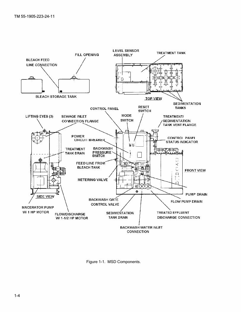
1-7. Location and Description of Major Components. Figure 1-1 shows the location of major MSD components. The following information concerns dataplates on components in the marine sanitation system. a. Recording Identification Data. Serial numbers and model numbers are shown on dataplates on the
equipment. Since wear may cause dataplates (nameplates) or stencils on the equipment to become unreadable, serial numbers, model numbers, Control Parts List (CPL) numbers, and other appropriate data should be recorded. This information is important when servicing and when replacing or ordering parts.
b. Location of Dataplates (Nameplates).
(1) Marine Sanitation Device. The dataplate is located on the left side of the external framework on the electrical junction box (control panel assembly) end of the unit.
(2) Pumps. The dataplates on all pump units are located on the individual pump motor housings.
1-8. Equipment Data. The following is the general equipment data for the sanitation device and all associated components.
a. Sanitation Device Model ORCA IIA-36, by Envirovac Inc. Capacity: Sewage 1,080 gl (4,088 L) per day Persons 36 Dimensions and Weights: Height: 42.5 in (108 cm) Width: 18.5 in (47 cm) Length: 44 in (112 cm)

TM 55-1905-223-24-11
1-3
Dimensions and Weights continued: Dry Weight: 775 lb (352 Kg) Wet Weight: 1,075 lb (448 Kg) Allowable Pitch and Roll: 30 degrees Allowable Hydrostatic Head: 10 ft (3 m) water Bleach Requirement: 2.25 gl (8.5 L) per day External Piping Connections: Sewage Inlet: 3 in (76.2 mm) 150# ANSI Flange Connection Sewage Outlet (at discharge pump): 0.75 in (19 mm) 150# ANSI Flange Connection Vent Outlet: 1.5 in (38.1 mm) 150# ANSI Flange Connection Backwash Inlet: 0.5 in (12.7 mm) 150# ANSI Flange Connection Electrical Connections: Input: 110/220 VAC, 1 phase, 50/60 Hz, 30 amp Current Draw: 115/220 VAC, 3.5 kva b. Associated Components. Treatment Tank Capacity: 17.5 gl (66.15 L) Sedimentation Modules: Quantity: 3 (split tanks in series, 6 total) Capacity: 30 gl (113.5 L) (10 gl each) Macerator: Waste King: 1 hp, 115/230 VAC, 60 Hz Flow Pump and Motor: Motor: Baldor, Model CL3503A 1.5 hp, 3,450 RPM 115/230 VAC, 60 Hz Pump: Tecumseh Model 23938 Impeller Diameter: 2.875 in (73 mm) Bleach Tank: Capacity, 10 gl (37.9L) Location Requirements: Horizontal: Within 10 feet (3 m) of the unit Vertical: Minimum of 1 foot (30.5 cm) above the unit Retention/Reduction Screen: Wire Cloth, 24/014 Sprinkler Head Pressure: 30 psi (2.1 Kg/cm2) Flow: 3.6 gpm (16.4 L/min) Commode Warning Light 110/120 VAC 1-9. Safety, Care, and Handling. Safety precautions must be observed at all times while performing maintenance. General WARNINGS and first-aid data appear in the front of this manual. Review all safety information before starting any task. Carefully read through an entire maintenance procedure before performing any maintenance function. Make sure the task can be done safely. All WARNINGS, CAUTIONS, and NOTES are of great importance to your safety and the safety of the equipment.
TM 55-1905-223-24-11
1-4
Figure 1-1. MSD Components.
TM 55-1905-223-24-11
1-5
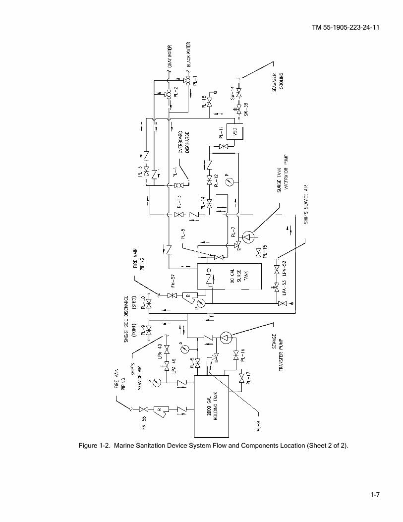
SECTION III. PRINCIPLES OF OPERATION 1-10. General. Figure 1-2 illustrates how the sanitation device interfaces with other external components in the sewage system. For the operation of these individual system components, refer to the LCU Operator’s Manual, TM 55-1905-223-10. 1-11. System Functional Description. The following describes the sanitation system design and the sewage treatment process. a. System Description. (1) The Marine Sanitation Device is a self contained unit. All of the major components are located
within the enclosure panels of the unit, with the exception of the bleach tank, commode warning light, and remote status indicator panel.
(2) The system is equipped with an electronic monitoring system which automatically controls the
treatment of sewage, warns of any motor shutdown, and pinpoints the problem motor. It also warns of any treatment tank overload condition, thus avoiding damage to other system components or to the vessel’s electrical supply.
(3) The control system comprises one modular unit. The control panel assembly (Figure 1-3) houses
the electronic monitoring circuit and an in-line circuit breaker. b. Treatment Process. (Figure 1-4.) (1) Blackwater and graywater from the surge tank enters the treatment tank of the MSD. The sewage
is macerated and chlorinated. The macerated sewage is continuously recirculated into the treatment tank until the solids are small enough to pass through the retention/reduction screen. The retention/reduction screen is continuously backwashed to prevent solid build up and clogging/plugging. Sewage particles that passed through the screen enter the inlet of the flow pump, which pumps the sewage into the sedimentation tanks. Any agglomerated solids fall to the bottom of the sedimentation tanks and are returned via the sludge flow control valve to the treatment tank for further processing. If pressure in the discharge line builds up above 35 psig (241.5 kPa), the pressure relief valve opens to allow the return of processed sewage into the treatment tank.
(2) The processed effluent is discharged from the MSD through a spring loaded check valve. The
check valve creates a back pressure to allow flow through the sludge return lines. The minimum pressure required to start opening is 5 psi (34.5 kPa). This pressure will increase as the discharge flow increases. The effluent is disinfected with a bleach solution (sodium hypochlorite and water) and chemical oxidation within the treatment tank. Disinfection is accomplished by a metering system (solenoid and needle valve) that meters an appropriate amount of bleach into the treatment tank. The bleach solution is stored in a 10 gallon tank mounted above the treatment tank.
(3) The level sensor assembly is located on the inlet side of the retention/reduction screen and consists
of four electrodes (ground, low level, demand level, and high level). The level of the sewage in the treatment tank in relation to the electrodes is sensed by the microprocessor in the circuit control board assembly.
(4) When the sewage level reaches the tip of the demand electrode, an 18 minute cycle is started. If
the low level electrode is uncovered after 18 minutes, the MSD stops processing sewage and goes into the standby mode. If the low level probe is covered after 18 minutes, another 18 minute cycle continues without interruption and the cycles are repeated, if necessary, until the low level probe is uncovered. If the sewage level covers the high level electrode, the HIGH LEVEL LED light on the status indicator (control panel) begins flashing. If the high level condition persists for 10 minutes, the MSD will shutdown automatically. During this automatic shutdown period, the LED light on the status indicator will remain illuminated. The MSD will not automatically restart after a power failure, the reset pushbutton must be depressed to restart the MSD system.

TM 55-1905-223-24-11
1-6
Figure 1-2. Marine Sanitation Device System Flow and Components Location (Sheet 1 of 2).
TM 55-1905-223-24-11
1-7
Figure 1-2. Marine Sanitation Device System Flow and Components Location (Sheet 2 of 2).

TM 55-1905-223-24-11
1-8
Figure 1-3. Marine Sanitation Device Control Panel Assembly.

TM 55-1905-223-24-11
1-9
1-12. Functional Description Of Components. The component descriptions are listed in the order of flow. See Figure 1-4 for location of item. a. Treatment Tank (1). Provides space for sewage retention and treatment. b. Retention/Reduction Screen (2). Retains larger solids in the treatment tank until they are broken down by
the macerator and able to pass through and into the sedimentation modules. c. Impact Sprinkler/Backwash Nozzles (3). Washes the retention/reduction screen to prevent clogging by
solid. d. Flow Pump (4). Moves the effluent from the treatment tank into the sedimentation tanks. e. Sedimentation Tanks (5). Three sets of split tanks (6 total) in series for the filtration and settlement of
suspended solids. f. Level Sensor Assembly (6). Monitors the treatment tank level by sending a signal to the electrical junction
box which controls pump operation. It is located inside the treatment tank. g. Macerator Pump (7). A garbage disposal type unit for shredding treated sewage. h. Backwash Pressure Gauge (8). Indicates the pressure on the backwash water inlet line. The gauge line
located in the front of the unit is installed in the backwash water line on the underside of the unit. i. Backwash Solenoid Valve (9). Controls the backwash water while the system is processing or is in the
rest period. It is located on the underside of the unit beneath the treatment tank area. j. Bleach Tank (10). Provides storage for the bleach solution. It is located separate from the unit and has a
gravity feed for delivering the bleach through a metering valve and to the optional metering solenoid valve on the unit.
k. Metering Valve (11). Meters the required amount of bleach solution into the treatment tank for disinfection
of the effluent. l. Metering Solenoid Valve (12). Electrically operated valve controls delivery of bleach from the bleach tank
to the unit. It operates only when the metering valve is open. m. Status Indicator (13). Indicates any motor malfunction or high level of sewage. n. Control Panel Assembly. (14). Provides location for the mode selector switch, microprocessor, electrical
connections, and is the control system that continually monitors motor operation and treatment tank conditions.
o. Vent Piping (15). Vents the sanitation device to the outside air. Vent float check valves within each
sedimentation tank cover prevent liquid from entering the vent piping system. p. Surge Tank (16). Provides short term storage prior to treatment tank to prevent overflow when system is
shutdown and prevent treatment tank from running low on effluent. q. Surge Pump (17). Transfers unprocessed sewage from the surge tank to the treatment tank, controlled by
level sensors. r. Commode Warning Light (18). Activated by the tank level indicator on the surge/holding tanks. Indicates
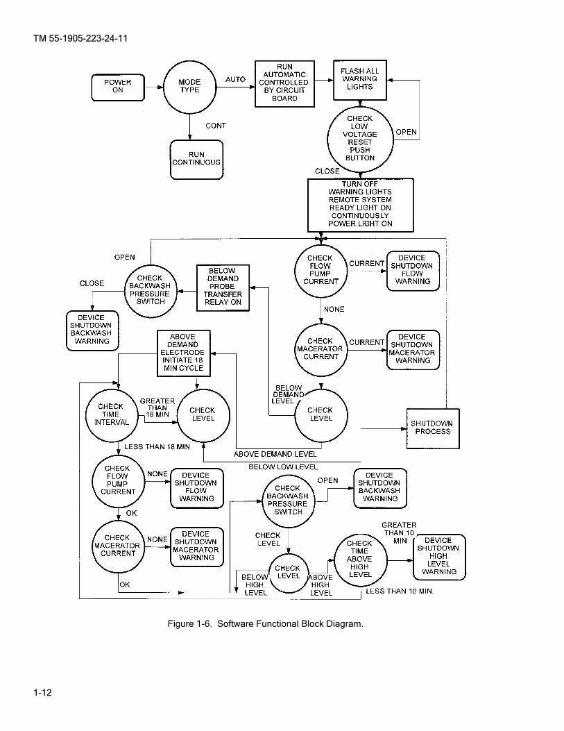
treatment tank is filled to capacity. 1-13. Hardware Interface. The MSD hardware interface details the interconnection and flow through the system. See Figure 1-5 for functional block diagram. 1-14. Software Interface. The MSD software interface shows the interconnection and signal flow through the system. See Figure 1-6 for software functional block diagram.

TM 55-1905-223-24-11
1-10
Figure 1-4. Functional Block Diagram/Interface.

TM 55-1905-223-24-11
1-11
Figure 1-5. Hardware Functional Block Diagram.
TM 55-1905-223-24-11
1-12
Figure 1-6. Software Functional Block Diagram.
TM 55-1905-223-24-11
2-1
CHAPTER 2
UNIT MAINTENANCE INSTRUCTIONS Page Section I Repair Parts, Special Tools; Test, Measurement, and Diagnostic Equipment (TMDE); and Support Equipment ..................................................2-1 Section II Service Upon Receipt ........................................................................................................2-1 Section III Unit Preventive Maintenance Checks and Services (PMCS) ............................................2-11 Section IV Unit Maintenance Troubleshooting ....................................................................................2-13 Section V Unit Maintenance Procedures............................................................................................2-26 Section VI Preparation for Storage or Shipment .................................................................................2-89
SECTION I. REPAIR PARTS, SPECIAL TOOLS; TEST, MEASUREMENT, AND DIAGNOSTIC EQUIPMENT (TMDE); AND SUPPORT EQUIPMENT
2-1. Common Tools and Equipment. For authorized common tools and equipment, refer to the Modified Table of Organization and Equipment (MTOE), CTA 50-970, Expendable/Durable Items (Except: Medical, Class V, Repair Parts, and Heraldic Items), CTA 50-909, Field and Garrison Furnishings and Equipment or CTA 8-100, Army Medical Department Expendable/Durable Items, as applicable to your unit. 2-2. Special Tools, TMDE, and Support Equipment. Special tools; test, measurement, and diagnostic equipment; and support equipment requirements are listed and illustrated in the Repair Parts and Special Tools List (RPSTL), TM 55-1905-223-24P. These items are also listed in the Maintenance Allocation Chart (MAC), Appendix B of this manual. 2-3. Repair Parts. Repair parts are listed and illustrated in the Repair Parts and Special Tools List (RPSTL), TM 55-1905-223-24P.
SECTION II. SERVICE UPON RECEIPT 2-4. Checking Unpacked Equipment. a. Inspect the equipment for damage incurred during shipment. If the equipment has been damaged, report
the damage in accordance with the instructions of DA PAM 750-8. b. Check the equipment against the packing slip to see if the shipment is complete. Report all discrepancies
in accordance with the instructions of DA PAM 750-8. c. Check to see whether the equipment has been modified. d. Remove and replace protective caps, plugs, inserts, wrappings, and tape when inspection/inventory is
completed. Inspect piping openings for damage. Wipe off dirt, grease, or protective films at time of installation.
e. Remove chocks from resilient mounted components. 2-5. Deprocessing Unpacked Equipment. After receipt and inspection of unpacked equipment, make sure that all packing materials, temporary braces, masking tape, etc., are removed from the material before installation. 2-6. Preliminary Servicing and Adjustment. To ensure that the sanitation unit will be adequately inspected, serviced, and operationally tested before it is subjected to normal everyday use, the following procedures are required to be performed.

TM 55-1905-223-24-11
2-2
a. Device Installation Checks. ________ WARNING
Turn electrical power OFF to the MSD system to avoid personal injury. Lockout/Tagout according to vessel SOP.
(1) Mechanical Installation Check. Check pump, motor, macerator, and connections to make certain components are securely mounted, bolts tight, and so forth.
(2) Piping Installation Check. Before startup, check that the following connections are plumbed and
fittings secured (Figure 1-2): (a) Sewage Inlet Flange Connection. (b) Sewage Discharge Flange Connection. (c) Backwash Feed Flange Connection. (d) Vent Piping Flange Connection. (e) Bleach Tank Tubing Connections.
NOTE
Perform a general check on all visible Poly Vinyl Chloride (PVC) piping and hose connections. Ensure that all connections are tight and hose clamps tightened.
(3) Electrical Installation Check. Before starting, check the following wiring (refer to Figure 2-3): (a) Make visual check of control panel connections. If any unterminated wires are found, review
drawing 19207 LCU2K-00593-01 and reinstall. (b) Check the main power line. (c) Make certain that fuses are installed. (d) Ensure that all POWER switches (circuit breakers) are in the OFF position. b. Operation.
________ WARNING
Personnel should not operate the device unless they are familiar with the procedures contained in this manual.
(1) Controls And Indicators. Controls and indicators used during device operation are listed in Table 2-1 and their location shown in Figure 2-1. (2) Control Station Indicator. The EOS has an ORCA IIA Control Station Indicator and provides
indications as listed in Table 2-3 and shown in Figure 2-2.
NOTE
The green POWER ON indicator remains illuminated continuously during normal operation. When any status indicator is illuminated continuously, a problem exists (Table 2-2).
c. Initial Start-Up Procedure. Ensure device installation check procedures, Paragraph 2-6.a., have been accomplished. Proceed as follows:
TM 55-1905-223-24-11
2-3
________ WARNING
Ensure that the vessel’s primary circuit breaker and the control panel circuit breaker are in the OPEN (OFF) position at the start of these procedures.
________ WARNING
Toxic and flammable vapors are generated in the sewage system. Provide ventilation from outside source before removing treatment tank covers. Avoid open flames and prolonged breathing of fumes.
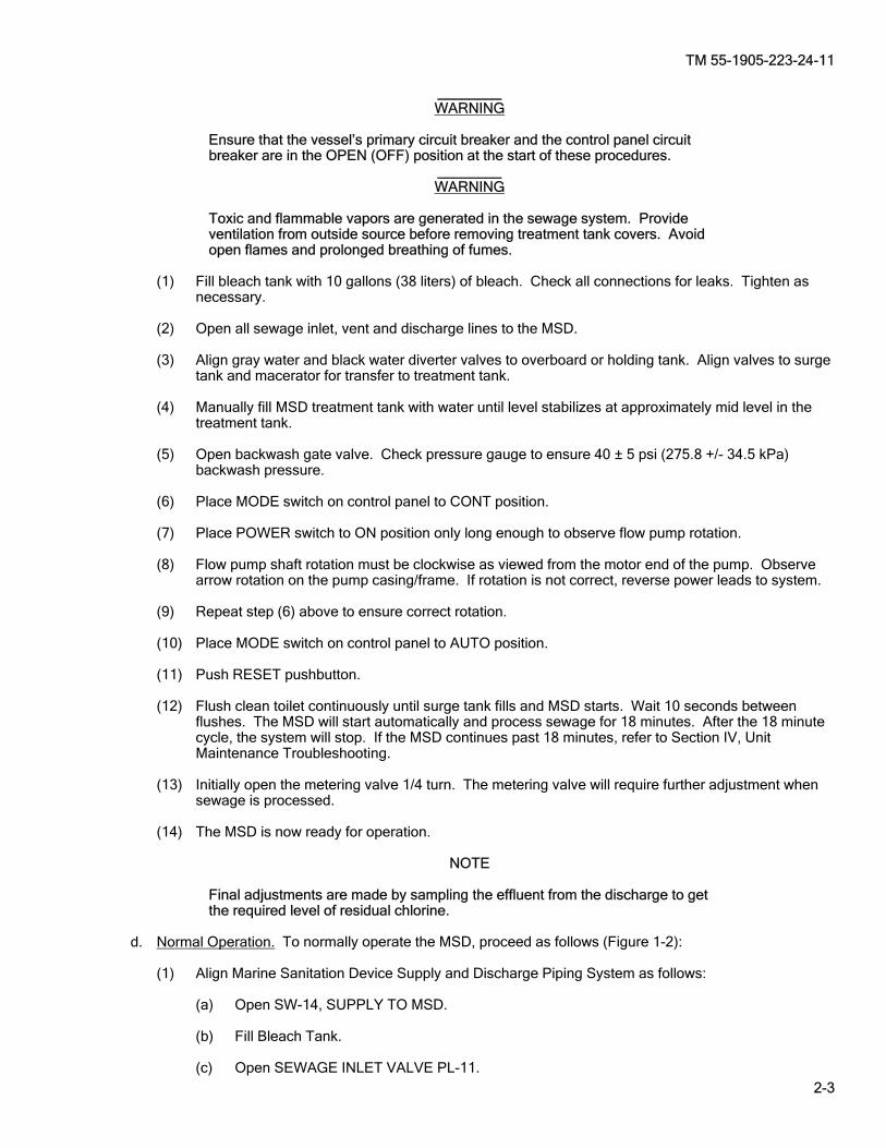
(1) Fill bleach tank with 10 gallons (38 liters) of bleach. Check all connections for leaks. Tighten as necessary.
(2) Open all sewage inlet, vent and discharge lines to the MSD. (3) Align gray water and black water diverter valves to overboard or holding tank. Align valves to surge
tank and macerator for transfer to treatment tank. (4) Manually fill MSD treatment tank with water until level stabilizes at approximately mid level in the
treatment tank. (5) Open backwash gate valve. Check pressure gauge to ensure 40 ± 5 psi (275.8 +/- 34.5 kPa) backwash pressure. (6) Place MODE switch on control panel to CONT position. (7) Place POWER switch to ON position only long enough to observe flow pump rotation. (8) Flow pump shaft rotation must be clockwise as viewed from the motor end of the pump. Observe
arrow rotation on the pump casing/frame. If rotation is not correct, reverse power leads to system. (9) Repeat step (6) above to ensure correct rotation. (10) Place MODE switch on control panel to AUTO position. (11) Push RESET pushbutton. (12) Flush clean toilet continuously until surge tank fills and MSD starts. Wait 10 seconds between
flushes. The MSD will start automatically and process sewage for 18 minutes. After the 18 minute cycle, the system will stop. If the MSD continues past 18 minutes, refer to Section IV, Unit Maintenance Troubleshooting.
(13) Initially open the metering valve 1/4 turn. The metering valve will require further adjustment when
sewage is processed. (14) The MSD is now ready for operation.
NOTE
Final adjustments are made by sampling the effluent from the discharge to get the required level of residual chlorine.
d. Normal Operation. To normally operate the MSD, proceed as follows (Figure 1-2): (1) Align Marine Sanitation Device Supply and Discharge Piping System as follows: (a) Open SW-14, SUPPLY TO MSD. (b) Fill Bleach Tank. (c) Open SEWAGE INLET VALVE PL-11.
TM 55-1905-223-24-11
2-4
(d) Ensure, BLACKWATER DIVERTER valve PL-1 and GRAYWATER DIVERTER valve PL-2 are aligned to flow to MSD.
(e) Open PL-4, OVBD DISCH and PL-3, MSD-OVBD DISCH. (2) Place MODE switch to AUTO position. (3) Place POWER switch to ON position. (4) Push LOW VOLTAGE RESET pushbutton switch.
NOTE
In the event of power failure, the MSD does not reset automatically. LOW VOLT- AGE RESET must be made after any power interruption or intentional shutdown.
(5) Device will now operate automatically in 18 minute cycles as required. See Figure 1-4 for Functional Block Diagram/Interface.
NOTE
If any status LED indicator (red) is on continuously, a problem exists. Refer to Section IV, Unit Maintenance Troubleshooting. Refer to Table 2-1 for light status/system condition and Table 2-2 for Status Indicator Reference.
(6) POWER ON LED indicator is continuously illuminated.
________ WARNING
The CONT mode of operation should be used only in an emergency condition since the automatic control of the MSD is bypassed. Constant operator attention is required during the CONT operation of the MSD.
e. Emergency Operation. In the event of a microprocessor failure, sewage can be treated with the MSD in the continuous mode, for short periods of time.
(1) Place MODE switch to CONT position. (2) Place POWER circuit breaker to ON position. f. Shutdown/Storage Procedure. If for any reason, the MSD is to be out of use for an extended period of
time, proceed as follows: ________ WARNING
Ensure compliance with Federal and international laws prior to overboard discharge of untreated sewage.
(1) Allow all effluent to be discharged from the MSD IAW local directives. (2) Fill treatment tank with clean water and allow entire MSD to flush once. (3) When the MSD completes discharge of the rinse water and shuts down, place MODE SWITCH to
OFF position. (4) Close sewage inlet (PL-11 and PL-3) and seawater supply to MSD (SW-14). (5) Close bleach tank isolation valve. (6) Place ships power switch to OFF position. (7) Refer to Paragraph 2-6.g. to drain the MSD.

TM 55-1905-223-24-11
2-5
Table 2-1. Controls and Indicators
ITEM NO. CONTROL/INDICATOR Figure 2-1 FUNCTION
POWER Switch 1 Controls power application to MSD and protects (Circuit Breaker) the system. MODE Switch 2 Places device in automatic operation (normal) AUTO - - - CONT mode or in continuous mode.
LOW VOLTAGE RESET 3 Resets system after power interruption and Pushbutton Switch when macerator, flow pump, or backwash
requires a reset. POWER ON LED Indicator 4 Illuminates when power is applied via circuit (green) breaker. Remains illuminated as long as power is applied. MACERATOR LED Indicator 5 Indicates macerator pump failure if it stays illum- (red) inated. FLOW LED Indicator 6 Indicates flow pump failure if it stays illuminated. (red) BACKWASH LED Indicator 7 Indicates absence of backwash water pressure if (red) LED stays illuminated. HIGH LEVEL LED Indicator 8 Flashing light indicates high level and that (red) system is trying to clear condition. Device will
shutdown if light is flashing for 10 minutes or more. After 10 minutes, the light stays illum-inated.
COMMODE WARNING Light 9 Indicates treatment tank is filled to capacity. (red).
Table 2-2. Status Indicator Reference
LIGHT STATUS SYSTEM CONDITION POWER ON light illuminated; all other lights off System on, processing sewage. POWER ON light illuminated; MACERATOR light continuously illuminated
Macerator pump failure - high current condition.
POWER ON light illuminated, FLOW light continuously illuminated
Flow pump failure - high current condition.
POWER ON light illuminated; BACKWASH light continuously illuminated
Backwash pressure too low or nonexistent.
POWER ON light illuminated; HIGH LEVEL light continuously flashing
Indicates high level and that system is trying to clear condition.
POWER ON light illuminated; HIGH LEVEL light continuously illuminated
High level in treatment tank - automatic shutdown after 10 minutes.
Table 2-3. EOS Control Station Indicator
CONTROL/INDICATOR Figure 2-2 FUNCTION
ORCA IIA CONTROL STATION 1 INDICATOR (amber) Indicator OFF No Power to ORCA Indicator ON (Steady) ORCA Operational Indicator FLASHING ORCA Requires Attention

TM 55-1905-223-24-11
2-6
Figure 2-1. Controls and Indicators.

TM 55-1905-223-24-11
2-7
Figure 2-2. EOS Control Station Indication.

TM 55-1905-223-24-11
2-8
Figure 2-3. Typical Shipboard Electrical Connections.
TM 55-1905-223-24-11
2-9
g. Drain MSD Procedure. Drain MSD for prolonged storage and where there is a possibility of freezing. (1) Perform Paragraph 2-6.h. steps 1 through 7. (2) Place a suitable container under each drain plug to catch waste water. (3) Remove the drain plug at the Macerator discharge elbow. (4) Remove the drain plug at the Flow Pump housing. (5) Remove the drain plug for the sludge return line, located on the unit foundation, below the Flow
Pump motor. (6) Drain the overboard discharge line and the backwash water supply line, loosen the bolts at the
connection flanges and pry them loose until all liquid is drained.
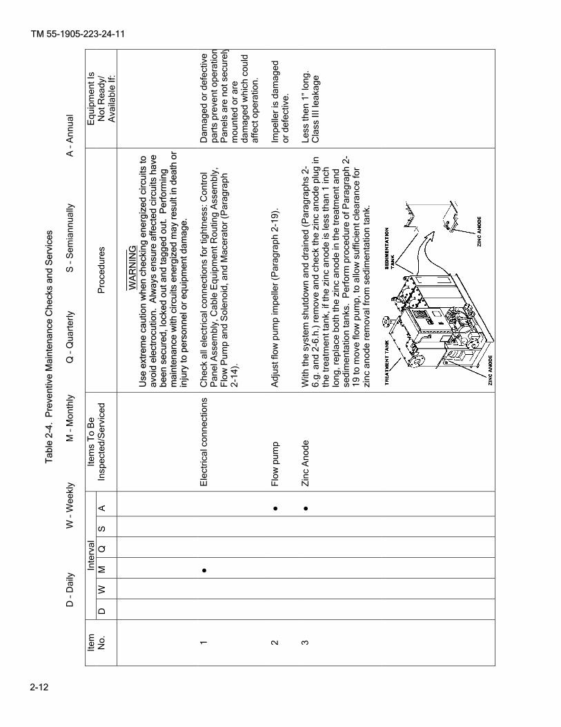
NOTE If the zinc anode requires replacement, perform item 10 of Table 2-4 at the completion of draining the MSD.
(7) Ensure there is no liquid in the backwash supply line between the Solenoid Valve and the sprinkler head or nozzles, remove the low pressure switch line (at the switch end) and let it drain. Reconnect low pressure switch line when draining is complete.
(8) Empty the chlorine tank and disposed of chlorine IAW regulations. h. Flushing MSD System. This procedure addresses the biologically safe way to flush out hazards and
make working on the MSD system much safer. The hazard warnings and cautions should still be adhered to regardless of how safe the system might be. To flush the MSD, proceed as follows:
(1) Place the POWER circuit breaker for the sewage transfer pump to the OFF position. (2) Place the MSD Control Panel circuit breaker to the OFF position. (3) Remove the treatment tank inspection cover. (4) Fill the treatment tank with fresh water to the top float switch level, replace the treatment tank
inspection cover, but do not bolt.
CAUTION Do not operate the MSD with just the backwash pump and the chlorinator when the treatment tank is empty, unless you are securing it for immediate repairs/maintenance and placing it back in service after repairs are complete. Doing so will create a hyper-chlorinated mix which may be corrosive to the Macerator and the Flow Pump.
(a) If fresh water is not available to fill the treatment tank use the backwash pump to rinse treatment tank. 1. Turn off the Chlorine Metering Valve. 2. Place the MSD Control Panel circuit breaker to the ON position and the MODE switch in the CONT position.
TM 55-1905-223-24-11
2-10
3. Ensure that backwash water is flowing into the treatment tank, by looking through the clear inspection cover. If no clear cover is installed, do so by observing the pressure gauge. The gauge pressure will fluctuate as the solenoid valve opens/closes.
CAUTION
If the unit is allowed to run totally dry damage, to the flow pump impeller and mechanical seal is imminent.
4. If pump cavitation is heard or after 15 minutes secure the system and inspect flow pump to ensure the mechanical seal is cool to the touch. 5. Repeat steps 1 through 4 until systems backwash pump have been allowed to operate for a total of 30 minutes. 6. Place the MSD MODE switch and Control Panel circuit breaker to the OFF position. 7. Ensure the treatment tank is empty. Proceed to Step (8) below. (5) Place the MSD Control Panel circuit breaker to the ON position and the MODE switch in the CONT
position until the treatment tank is empty. (6) Repeat steps 3, 4 & 5 two times. (7) As soon as the unit is empty for a third time, place the MSD Control Panel circuit breaker to the OFF
position. (8) Perform repairs or maintenance IAW applicable repair procedure. (9) Install treatment tank inspection cover and tighten bolts removed in step 3.
TM 55-1905-223-24-11
2-11
SECTION III. UNIT PREVENTIVE MAINTENANCE CHECKS AND SERVICES (PMCS) 2-7. EExplanation of PMCS Table. PMCS is designed to keep the equipment in good working condition. This is accomplished by performing certain tests, inspections, and services. Table 2-4 lists items to be serviced and the procedures needed to accomplish the PMCS. The “Interval” column tells you when to perform a check or service. If needed, PMCS may be performed more frequently than the indicated interval. The “Procedures” column tells you how to perform the required checks and services. If your equipment does not perform as required, see Table 2-5, Troubleshooting and Table 3-2, Intermediate Direct Support Troubleshooting. Report any malfunctions or failures on a Equipment Inspection and Maintenance Worksheet. In the “TM” Number column on the DA Form 2404/5988E, record the appropriate Item Number from the PMCS table. The column labeled "Equipment is Not Ready/Available If:" of the PMCS Table 2-4 is not intended to imply the condition of the vessel. This column only indicates the condition of the equipment.
Tab
le 2
-4.
Pre
vent
ive
Mai
nten
ance
Che
cks
and
Ser
vice
s
D
– D
aily
W
– W
eekl
y M
– M
onth
ly
Q –
Qua
rter
ly
S –
Sem
iann
ually
A
– A
nnua
l
Inte
rval
Ite
m
No.
D
W
M
Q
S
A
Ite
ms
To
Be
Insp
ecte
d/S
ervi
ced
P
roce
dure
s E
quip
men
t Is
N
ot R
eady
/ A
vaila
ble
If:
_____
____
W
AR
NIN
G
Use
ext
rem
e ca
utio
n w
hen
chec
king
ene
rgiz
ed c
ircui
ts to
av
oid
elec
troc
utio
n. A
lway
s en
sure
affe
cted
circ
uits
hav
e be
en s
ecur
ed, l
ocke
d ou
t and
tagg
ed o
ut.
Per
form
ing
mai
nten
ance
with
circ
uits
ene
rgiz
ed m
ay r
esul
t in
deat
h or
in
jury
to p
erso
nnel
or
equi
pmen
t dam
age.
1
�
Ele
ctric
al c
onne
ctio
nsC
heck
all
elec
tric
al c
onne
ctio
ns fo
r tig
htne
ss: C
ontr
ol
Pan
el A
ssem
bly,
Cab
le E
quip
men
t Rou
ting
Ass
embl
y,
Flo
w P
ump
and
Sol
enoi
d, a
nd M
acer
ator
(P
arag
raph
2-
14).
Dam
aged
or
defe
ctiv
e pa
rts
prev
ent o
pera
tion
Pan
els
are
not s
ecur
ely
mou
nted
or
are
dam
aged
whi
ch c
ould
af
fect
ope
ratio
n.
2
�
Flo
w p
ump
A
djus
t flo
w p
ump
impe
ller
(Par
agra
ph 2
-19)
. Im
pelle
r is
dam
aged
or
def
ectiv
e.
3
�
Zin
c A
node
With
the
syst
em s
hutd
own
and
drai
ned
(Par
agra
phs
2-6.
g. a
nd 2
-6.h
.) r
emov
e an
d ch
eck
the
zinc
ano
de p
lug
in
the
trea
tmen
t tan
k, if
the
zinc
ano
de is
less
than
1 in
ch
long
, rep
lace
bot
h th
e zi
nc a
node
in th
e tr
eatm
ent a
nd
sedi
men
tatio
n ta
nks.
Per
form
pro
cedu
re o
f Par
agra
ph 2
-19
to m
ove
flow
pum
p, to
allo
w s
uffic
ient
cle
aran
ce fo
r zi
nc a
node
rem
oval
from
sed
imen
tatio
n ta
nk.
Less
then
1”
long
. C
lass
III l
eaka
ge
2-12
TM 55-1905-223-24-11
TM 55-1905-223-24-11
2-13
SECTION IV. UNIT MAINTENANCE TROUBLESHOOTING 2-8. Troubleshooting. Both a symptom index and a troubleshooting table are provided. The symptom index will help you locate the information you need for troubleshooting. See Figures 2-4 and 2-5 as aids in troubleshooting the electrical portion of the MSD system. Refer to Section V for unit maintenance procedures. Utilize a multimeter to perform continuity checks on switches, solenoids, and electrical wiring.
SYMPTOM INDEX
Troubleshooting Procedure (Table 2-5)
BLEACH
No bleach being supplied to the treatment tank.
COMMODE Commode warning lights activated by the tank level indicator on the surge/holding tanks.
CONTROL SYSTEM
High level status light stays illuminated continuously and MSD shuts down. BACKWASH status light stays illuminated continuously and system shuts down. MACERATOR status light stays illuminated continuously. FLOW PUMP status light stays illuminated continuously. POWER ON light does not illuminate when POWER DISCONNECT SWITCH is placed to ON and LOW VOLTAGE RESET push button is pressed. All other status lights do not illuminate.
One status indicator light does not illuminate other indicators illuminate properly.
Any status indicator fault light stays illuminated continuously and system does not shutdown.
Control System stops. High Level Warning Light Illuminated; Power On Light Illuminated. (Remote Status Indicator)
MODE SWITCH
Device operates properly in AUTO mode but does not operate when MODE switch is placed in CONT position.
Device operates properly in CONT mode but does not operate when MODE switch is placed in AUTO position.
Item 10
Item 11
Item 1
Item 2
Item 3
Item 4
Item 5
Item 6
Item 9
Item 12
Item 7
Item 8
Table 2-5 lists the common fault conditions that may be found during operation or maintenance of the equipment. Look for causes and do corrective actions in the order listed. This manual cannot list every symptom that may show up, and it cannot list all the possible causes and corrective actions. If a symptom is not listed, or if it keeps up after you have performed the corrective actions, notify your supervisor.

TM 55-1905-223-24-11
2-14
Table 2-5. Troubleshooting Malfunction Test or Inspection Corrective Action
NOTE
During all troubleshooting, it is assumed vessel external power source is operating correctly and all applicable valves are open.
1. High level status light stays illuminated continuously and MSD shuts down. STEP 1. Plugged screen and/or defective impact sprinkler/backwash nozzle. Remove and clean screen (Paragraph 2-15) and/or replace impact sprinkler/backwash nozzle (Paragraph
2-21). STEP 2. Plugged discharge line or discharge line valve is in closed position. Clear overboard discharge line or open discharge line valve. STEP 3. High level electrode is shorted. Remove level sensor assembly (Paragraph 2-17). Check for continuity between leads of electrodes in
level sensor assembly (TB3, terminals 10 through 15, Figure 2-5, Sheet 1): Each lead should be isolated. STEP 4. Flow pump operating at reduced capacity. Inspect and test (Paragraph 2-19).
________ WARNING
The CONT mode of operation should be used only in an emergency condition since the automatic control of the MSD is bypassed. Constant operator attention is required during the CONT operation of the MSD.
STEP 5. Excessive demand on system. Change MSD Selector Switch from AUTO to CONT (2, Figure 2-1) until demand is reduced. STEP 6. Commode stuck in flush mode. Check commodes for over usage or stuck flush valve, repair as required. STEP 7. Improper transfer pump flow rate. Change transfer pump to a lower flow rate. 2. BACKWASH status light stays illuminated continuously and system shuts down.
NOTE For information regarding the backwash pressure regulator and wye type strainer refer to TM 55-1905-223-10 and TM 55-1905-223-24-18-1.
STEP 1. No backwash water being supplied to the unit (proper reading on the backwash gauge). Check to see if auxiliary seawater pump is on line and properly aligned. Start auxiliary seawater pump
and verify proper alignment. STEP 2. Lack of backwash water pressure. Verify that water is being supplied to MSD. Check/clean backwash supply strainer. STEP 3. Defective impact sprinkler/backwash nozzle. Replace impact sprinkler/backwash nozzle (Paragraph 2-21).
TM 55-1905-223-24-11
2-15
Table 2-5. Troubleshooting - CONT Malfunction Test or Inspection Corrective Action STEP 4. Check for loose connection or broken wiring to the backwash solenoid valve. Check connection and wiring to the solenoid valve and correct as necessary (Paragraph 2-13). STEP 5. Defective backwash solenoid valve. Replace backwash solenoid valve (Paragraph 2-21). STEP 6. Defective backwash pressure switch. Replace backwash pressure switch (Paragraph 2-12). STEP 7. Gate valve closed. Open gate valve.
NOTE
System shall continuously be checked for leaks. If leaks exist, shutdown system (if not automatically shutdown), place circuit breaker to “OFF.” Replace and/or repair PVC piping, joints, hoses, etc., to return the system to a leak proof condition.
3. MACERATOR status light stays illuminated continuously. STEP 1. Macerator malfunction. Refer to Table 3-1 for macerator troubleshooting. STEP 2. Macerator motor hums, but macerator does not operate. Jammed grind element. Clear jam (Paragraph 2-18). 4. FLOW PUMP status light stays illuminated continuously. STEP 1. Flow pump malfunction, impeller, bearings, plugged inlet, broken mount or bent shaft. Remove and repair flow pump. Disassemble and replace defective component(s) (Paragraph 2-19). 5. POWER ON light does not illuminate when POWER DISCONNECT SWITCH is placed to ON and LOW
VOLTAGE RESET push button is pressed. All other status lights do not illuminate. STEP 1. MSD power source is not available. Verify circuit breaker is on, if circuit breaker is on and MSD power is still not available, troubleshoot power
source. STEP 2. MSD Circuit breaker tripped. Reset MSD circuit breaker. STEP 3. Defective MSD circuit breaker, or loose connections. Tighten loose connections or replace MSD circuit breaker if required (Paragraph 2-13). STEP 4. Defective microprocessor or POWER ON light (LED). Replace/repair microprocessor (Paragraph 2-13). 6. One status indicator light does not illuminate other indicators illuminate properly. STEP 1. Defective applicable LED(s). Check and tighten loose connections (Paragraph 2-12). Replace/repair microprocessor (Paragraph 2-13).

TM 55-1905-223-24-11
2-16
Table 2-5. Troubleshooting - CONT Malfunction Test or Inspection Corrective Action 7. Device operates properly in AUTO mode but does not operate when MODE switch is placed in CONT position. STEP 1. Defective MODE switch. Replace MODE switch (Paragraph 2-13). STEP 2. Loose connections. Check and tighten loose connections (Paragraph 2-13). 8. Device operates properly in CONT mode but does not operate when MODE switch is placed in AUTO position. STEP 1. Faulty or malfunctioning level sensor assembly. Conduct level sensor assembly test (Paragraph 2-17). STEP 2. Defective MODE switch. Replace MODE switch (Paragraph 2-13). STEP 3. Loose connections. Check and tighten loose connections (Paragraph 2-13). STEP 4. Defective microprocessor. Check wiring connections (Paragraph 2-13). Replace/repair microprocessor (Paragraph 2-13). 9. Any status indicator fault light stays illuminated continuously and system does not shutdown. STEP 1. Defective microprocessor. Check wiring connections (Paragraph 2-13). Replace/repair microprocessor (Paragraph 2-13). STEP 2. Defective motor contactor. Replace/repair contactor (Paragraph 2-13). STEP 3. Defective relay board. Replace/repair relay board (Paragraph 2-13). 10. No bleach being supplied to the treatment tank.
________ WARNING
CHEMICAL HAZARD. Personal protective equipment (PPE) must be worn to avoid contact with skin and splashing in eyes. Avoid prolonged breathing of fumes.
STEP 1. Check to see if there is no bleach in tank. Add bleach and check bleach tank for leaks. Replace tank if necessary (Paragraph 2- 23). STEP 2. Check to see if metering valve is closed. Open metering valve by turning counterclockwise (Figure 1-1). STEP 3. Check for restricted supply. Check line for restriction and clear as necessary. STEP 4. Check to see if metering solenoid valve is defective. Replace metering solenoid valve (Paragraph 2-12).
TM 55-1905-223-24-11
2-17
Table 2-5. Troubleshooting - CONT Malfunction Test or Inspection Corrective Action 11. Commode warning lights activated by the tank level indicator on the surge/holding tanks.
CAUTION
Do not flush commodes with tank full.
STEP 1. Check to see if treatment tank is full. Refer to Item 12 of this table. 12. Control System stops. High Level Warning Light Illuminated; Power On Light Illuminated. (Remote Status
Indicator). STEP 1. Check to see if treatment tank is full. Wait about 9 minutes for sewage level to be reduced to 80
percent of tank capacity. The High Level Light should then go OUT. If, after 9 minutes, the unit automatically shuts down and both lights remain illuminated:
a. Observe that treatment tank is full. b. Flush the MSD (Paragraph 2-6.h). c. Drain the MSD (Paragraph 2-6.g).

TM 55-1905-223-24-11
2-18
Figure 2-4. Power Diagram, 220/230 V, 1 Phase, 50/60 Hz, 20 Amps, 2 Pole Breaker.
TM 55-1905-223-24-11
2-19
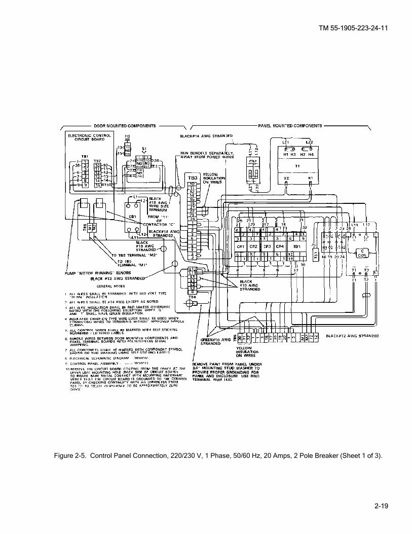
Figure 2-5. Control Panel Connection, 220/230 V, 1 Phase, 50/60 Hz, 20 Amps, 2 Pole Breaker (Sheet 1 of 3).
TM 55-1905-223-24-11
2-20
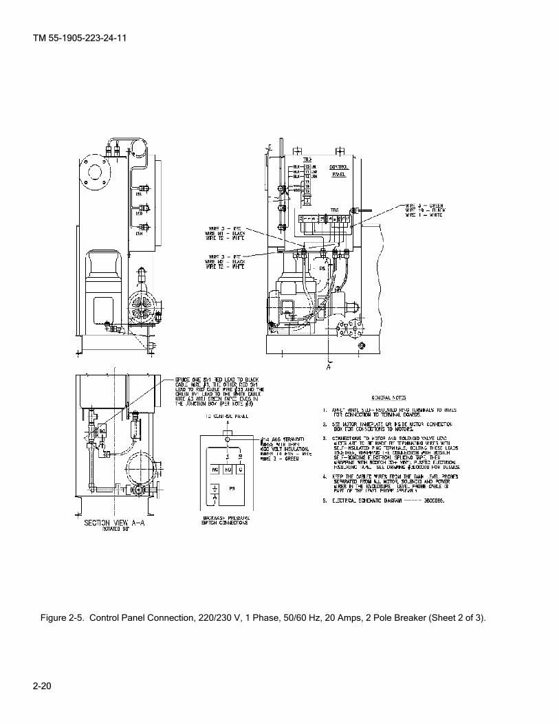
Figure 2-5. Control Panel Connection, 220/230 V, 1 Phase, 50/60 Hz, 20 Amps, 2 Pole Breaker (Sheet 2 of 3).
TM 55-1905-223-24-11
2-21
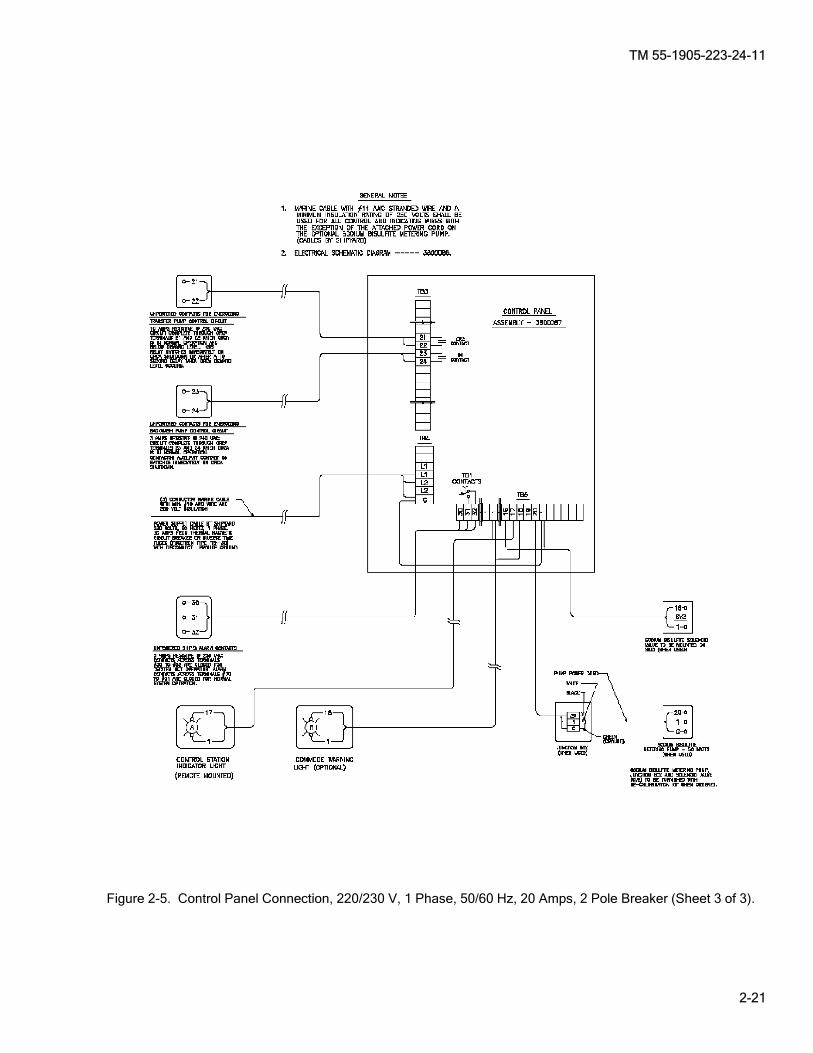
Figure 2-5. Control Panel Connection, 220/230 V, 1 Phase, 50/60 Hz, 20 Amps, 2 Pole Breaker (Sheet 3 of 3).
TM 55-1905-223-24-11
2-22
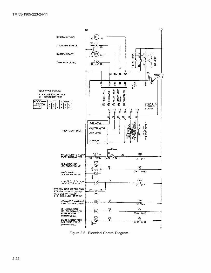
Figure 2-6. Electrical Control Diagram.
TM 55-1905-223-24-11
2-23
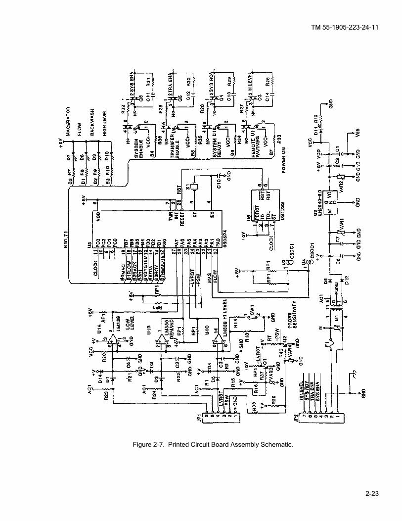
Figure 2-7. Printed Circuit Board Assembly Schematic.

TM 55-1905-223-24-11
2-24
Figure 2-8. Printed Circuit Board Assembly Component Location.
TM 55-1905-223-24-11
2-25
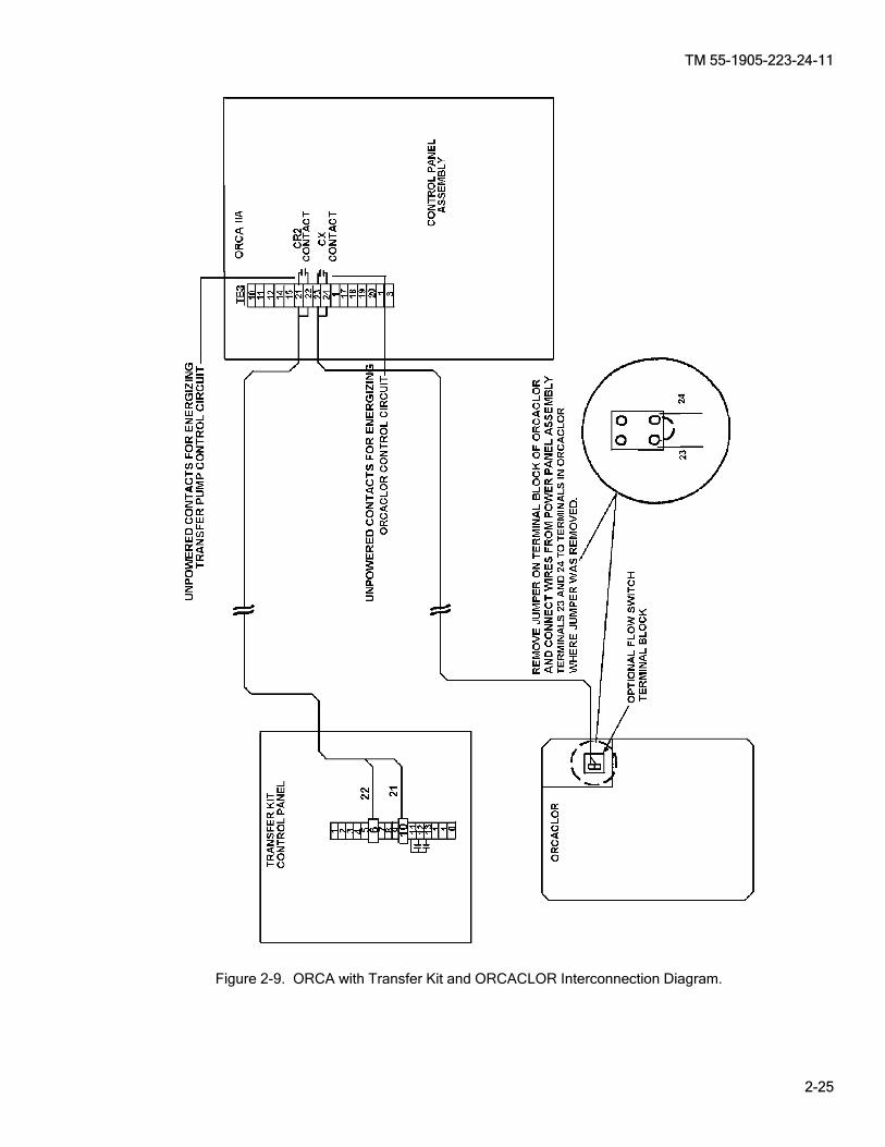
Figure 2-9. ORCA with Transfer Kit and ORCACLOR Interconnection Diagram.
TM 55-1905-223-24-11
2-26
SECTION V. UNIT MAINTENANCE PROCEDURES 2-9. GGeneral. This section provides unit maintenance for the marine sanitation device. The tasks are for inspection, service, adjustment, removal and replacement of subassembly components. These tasks are addressed in the following paragraphs.
________ WARNING
GAS HAZARD. A serious potential hazard associated with sewage systems is hydrogen sulfide (H2S). It is a colorless, flammable, toxic gas with a characteristic smell of rotten eggs at low concentrations. However the sense of smell is lost after 2-15 minutes of exposure making it impossible to smell dangerous concentrations. The permissible exposure limit (PEL) for H2S is 10 parts of H2S for every million parts of air (commonly expressed as 10 ppm H2S). The IDLH (Immediately Dangerous to Life or Health) limit is 100 ppm H2S. In addition when H2S burns, it produces another very toxic gas, sulfur dioxide (SO2). For additional information, refer to Naval Ships’ Technical Manual (NSTM) Chapter 593, POLLUTION CONTROL, S9086–T8–STM-010.
________ WARNING
CHEMICAL HAZARD. Personal protective equipment (PPE) must be worn to avoid contact with skin and splashing in eyes. Avoid prolonged breathing of fumes.
________ WARNING
DISEASE HAZARD. Good personal hygiene habits by those operating and servicing the MSD are imperative. Washing of hands with hot, potable water and disinfectant soap should be accomplished after coming in contact with sewage or any contaminated equipment. Personnel shall not be allowed to eat, smoke, or drink, in the MSD pump room. Personnel with skin abrasions, punctures, or any other wounds shall not be allowed to service MSD equipment. In order to minimize the risks of health and sanitation hazards associated with the MSD, personnel. shall follow sanitary and hygienic practices contained in section 4 of NSTM Chapter 593, S9086–T8–STM-010. When performing maintenance, which requires disassembly of sewage equipment or when contact with sewage is possible, personnel protective equipment (PPE) specified in section 4 of NSTM Chapter 593, S9086–T8–STM-010 shall be donned.
________ WARNING
TOXIC AND FLAMMABLE HAZARD. A potential sewage system hazard is fire or explosion. The sewage holding tank and system piping should be considered to contain some type of combustible. Combustible gases, such as hydrogen sulfide and methane, may be formed inside the holding tank or piping due to biological decomposition of organics. Under normal operating conditions, most other gases that are potentially flammable do not form in concentrations high enough to approach the explosive limit. Fuels may also be inadvertently collected in holding tanks from deck drains or through common bulkheads, and decks between fuel oil tanks and holding tanks, which have failed. In order to minimize the potential for a fire or explosion hazard, the following precautions should be taken: 1. Ensure the installed holding tank aeration system (if installed) is operated to
reduce the amount of hydrogen sulfide.

TM 55-1905-223-24-11
2-27
2. Follow NSTM Chapter 593, (Pollution Control) when conducting hot work on any part of a sewage system.
3. Use only approved intrinsically safe, spark-proof or explosion-proof
equipment when flammable or explosive vapors, gases, or materials are present. Control all other potential ignition sources and provide adequate fire protection measures for the specific exposure.
4. Never permit smoking, eating, or drinking inside the sewage system spaces. 5. Always exercise caution when cleaning up fuel or flammable liquid spills.
These fluids shall be containerized and sealed for shore disposal by the base public works department. The disposal of flammable or toxic liquids to the sewage holding tank by way of the waste or sewage drains is strictly prohibited.

TM 55-1905-223-24-11
2-28
2-10. The unit level replacement and repair tasks of the marine sanitation device are accomplished through maintenance procedures in paragraphs 2-11 thru 2-24 of this chapter. 2-11. Treatment Assembly, Sewage (Figure 2-10). This task covers: a. Inspect, b. Service, c. Replacement.
INSPECT Inspection of the sewage treatment unit assembly is accomplished through Preventive Maintenance Checks and Services (PMCS, TM 55-1905-223-10) and maintenance procedures. For operational check, startup, and normal operation, refer to Paragraph 2-6. SERVICE Service to the sewage treatment unit assembly is accomplished through Preventive Maintenance Checks and Services (PMCS, TM 55-1905-223-10). REMOVAL
________ WARNING
Use extreme caution when checking energized circuits to avoid electrocution. Always ensure affected circuits have been secured, locked out and tagged out. Performing maintenance with circuits energized may result in death or injury to personnel or equipment damage.
a. Turn electrical power to the unit OFF and tag.
INITIAL SETUP Tools Equipment Condition Tool kit, general mechanic's, System flushed and drained (Paragraph 2-6). 5180-00-699-5273 TM 55-1905-223-10, marine sanitation system secured, Tool kit, electrician's, locked out and tagged (FM 55-502). 5180-00-391-1087 All commodes tagged "Out of Service, Do Not Lifting fixture, P/N 3822512 Operate." Lifting straps, P/N 3375958 Torque wrench (ft-lb), 5120-01-125-5190 Materials/Parts Clamp, tubing, Item 5, Section II, Appendix C Disinfectant, Item 7, Section II, Appendix C Gloves, chemical, Item 8, Section II, Appendix C Goggles, Item 9, Section II, Appendix C Rags, wiping, Item 11, Section II, Appendix C Tape, Teflon, Item 17, Section II, Appendix C Warning tag, Item 18, Section II, Appendix C Cover gasket P/N 3700073 Container, closeable, 1 qt (for catching bleach runoff) Container, closeable, 5 gal or larger, sealable (for catching sewage runoff)
MAINTENANCE OF MARINE SANITATION DEVICE

TM 55-1905-223-24-11
2-29
b. Close external water supply valve to the backwash water line. c. Disconnect all cable connectors (10, Figure 2-10) to the electrical junction box. d. Open the junction box and do the following: (1) Label and disconnect all external wires to the junction box. (2) Pull the external wires through the bottom of the junction box. Mark the locations where each cable
is removed so that it can be installed in the same connector on the new unit. ________ WARNING
Toxic and flammable vapors are generated in the sewage system. Provide ventilation from outside source before removing covers, drain plugs, hoses, and fittings. Avoid open flames and prolonged breathing of fumes.
e. Plug all openings to the unit and the incoming lines as they are disconnected. Use appropriate pipe plugs, caps, rags, or equivalent.
f. Disconnect vent connection (2, Figure 2-10) and plug the opening. g. Close the bleach metering valve (11, Figure 2-10).
________ WARNING
CHEMICAL HAZARD. Personal protective equipment (PPE) must be worn to avoid contact with skin and splashing in eyes. Avoid prolonged breathing of fumes.
h. Place a tubing clamp on the bleach line to the valve. Hold a container under the connection to catch bleach runoff, and disconnect the bleach line from the metering valve.
i. Close the backwash gate valve (8, Figure 2-10) on the MSD. Disconnect the backwash water supply at
the valve flange connection (6, Figure 2-10). j. Disconnect sewage inlet pipe (12, Figure 2-10) and plug the openings in the tank and in the inlet line. k. Disconnect sewage discharge line (5, Figure 2-10). Hold a container under the connection to catch any
sewage runoff while disconnecting. Plug openings. l. Remove the mounting screws, nuts, and washers (9) from the base of the unit (4, Figure 2-10). m. Connect a lifting fixture and straps to lifting eyes (13 and 3, Figure 2-10).
________ WARNING
Stand clear during lifting operations to avoid personal injury.
n. Hoist the treatment unit clear of its mounting and remove it from the compartment. o. Clean all spills with disinfectant. p. When the treatment unit has been removed to an outside location, remove the drain plug (7, Figure 2-10)
and drain excess effluent into a portable container for disposal.
TM 55-1905-223-24-11
2-30
________ WARNING
Toxic and flammable vapors are generated in the sewage system. Provide ventilation from outside source before removing treatment tank covers. Avoid open flames and prolonged breathing of fumes.
q. Remove the treatment tank cover (1, Figure 2-10) (Paragraph 2-15). r. Clean and flush the unit with fresh water and disinfectant. REPLACEMENT
NOTE
Do not install the treatment tank cover and gasket until the unit has been installed and inspected.
a. Attach the lifting fixture to lifting eyes and straps (13 and 3, Figure 2-10) and lift the new sanitation treatment unit into place on its mounting foundation.
b. Install mounting screws, nuts, and washers (9, Figure 2-10) in the base of the unit (4, Figure 2-10) and
tighten to 34 ft-lbs. c. Remove the lifting fixture and straps. d. Remove plug, and connect sewage discharge line (5, Figure 2-10). e. Remove the temporary inlet plug and connect the sewage inlet pipe (12, Figure 2-10). f. Connect the backwash water supply line to backwash gate valve flange connection (6, Figure 2-10).
NOTE
Ensure the bleach metering valve is closed when connecting tubing.
g. Connect the bleach line (tubing) to the metering solenoid valve (11, Figure 2-10). Remove the clamp that
was placed on the tubing during the removal process. h. Remove the temporary plug in the vent line and connect the vent pipe (2, Figure 2-10). i. Apply Teflon Tape to the threads and install the drain plug (7, Figure 2-10). j. Refer to tags and notes and run external wiring through the bottom connectors (10, Figure 2-10) on the
junction box. Make sure each cable is returned to the same location that it was removed from on the old unit. Tighten connectors until snug.
k. Refer to tags and connect all wiring inside the junction box. Make sure each wire is connected to its
proper terminal. l. Install tank access cover gasket and cover (Paragraph 2-15). m. Restore electrical power, start the unit, and conduct operational check (Paragraph 2-6). n. Operate the MSD (Paragraph 2-6) and check covers, gaskets, piping and hoses for leaks, correct as
necessary. o. Disinfect and remove all spills.

TM 55-1905-223-24-11
2-31
Figure 2-10. References Used When Replacing the Sanitation Device.
TM 55-1905-223-24-11
2-32
2-12. Control Panel Assembly Group. (Figure 2-11) This task covers: a. Inspect, b. Repair, c. Replacement.
INSPECT Inspection of the control panel assembly is accomplished through Preventive Maintenance Checks and Services (PMCS) Table 2-4 and maintenance procedures. REMOVAL
________ WARNING
Use extreme caution when checking energized circuits to avoid electrocution. Always ensure affected circuits have been secured, locked out and tagged out. Performing maintenance with circuits energized may result in death or injury to personnel or equipment damage.
NOTE
When removing electrical components, label all wiring as an aid in reassembly.
NOTE
Removal step a. applies to the control panel assembly. Paragraph 2-13 applies to control panel and module components.
a. To remove the control panel assembly (4, Figure 2-11) proceed as follows: (1) Label and disconnect wiring from flow pump (Paragraph 2-19), macerator (Paragraph 2-18) and
backwash solenoid valve (Paragraph 2-14). (2) Label and disconnect wiring from level sensors (Paragraph 2-17). (3) Label and disconnect wiring from metering solenoid valve and pressure switch (15 and 12, Figure
2-11).
INITIAL SETUP Tools Equipment Condition Tool kit, general mechanic's, TM 55-1905-223-10, marine sanitation system secured, 5180-00-699-5273 locked out and tagged (FM 55-502). Tool kit, electrician’s, 5180-00-391-1087 Materials/Parts Clamp, tubing Item 5, Section II, Appendix C Disinfectant, Item 7, Section II, Appendix C Rags, Wiping, Item 11, Section II, Appendix C Tape, Teflon, Item 17, Section II, Appendix C Warning tag, Item 18, Section II, Appendix C Container, Closeable, 1 qt (for catching bleach runoff)

TM 55-1905-223-24-11
2-33
(4) Remove control panel assembly by removing four screws (1), nuts (3) and washers (2) (Figure 2-11) from the control panel assembly and the MSD assembly. b. To remove metering valve (19, Figure 2-11) proceed as follows: (1) Close the bleach tank isolation valve. (2) Place a small container under the metering valve (19) during removal to catch bleach runoff from
the tube. (3) Remove straight tube adapter (20) from metering valve (19). (4) Remove metering valve (19) from pipe nipple (18). c. To remove metering solenoid valve (15, Figure 2-11) proceed as follows: (1) Close metering valve (19). (2) Disconnect wiring from metering solenoid valve (15) wires on TB5-1 and TB5-16 (Figure 2-5, Sheet 2) inside the control panel assembly (4). (3) Remove pipe elbows (6 and 17) from metering solenoid valve (15). (4) Remove metering solenoid valve (15) from conduit nipple (11). Removal of electrical wire for the
metering solenoid valve (15) may require loosening or removal of the electrical conduit coupling (10). d. To remove check valve (5, Figure 2-11) proceed as follows: (1) Remove pipe elbow (6) from check valve (5). (2) Remove check valve from pipe nipple (13). e. To remove backwash pressure switch (12, Figure 2-11) proceed as follows: (1) Remove tubing (7) by unscrewing pipe elbow (6). (2) Remove check valve (5) from pipe nipple (13). Retain check valve (5) for installation. (3) Remove 4 screws from cover of backwash pressure switch (12). Retain cover and screws for
installation. (4) Label and disconnect wires from backwash pressure switch (12), wire TB3-14 from N.O. contact, wire TB3-15 from C contact and wire TB3-3 from Ground. (5) Remove conduit nut (10) and lower backwash pressure switch (12) and nipple (11) out and away
from control panel assembly (4). (6) Remove pipe nipple (13), pipe tee (14) and pipe elbow (6) from backwash pressure switch (12).
Retain pipe nipple (13), pipe tee (14) and pipe elbow (6) for installation. (7) Remove backwash pressure switch (12) from its enclosure. REPAIR Repair of the metering valve, metering solenoid valve, check valve and backwash pressure switch is by replacement. a. To repair the metering valve, proceed as follows:

TM 55-1905-223-24-11
2-34
(1) Remove metering valve as described in removal step b. (2) Install new metering valve as described in replacement step b. b. To repair the metering solenoid valve proceed as follows: (1) Remove metering solenoid valve as described in removal step c. (2) Install new metering solenoid valve as described in replacement step c. c. To repair the check valve proceed as follows: (1) Remove check valve as described in removal step d. (2) Install new check valve as described in replacement step d. d. To repair the backwash pressure switch proceed as follows: (1) Remove backwash pressure switch as described in removal step e. (2) Install new backwash pressure switch as described in replacement step e. REPLACEMENT a. To replace the control panel assembly (4, Figure 2-11) proceed as follows: (1) Remove the control panel assembly (4) proceed as described in removal step a. (2) Install control panel assembly by installing four screws (1), nuts (3) and washers (2) (Figure 2-11)
on the control panel assembly and the MSD assembly. (3) Connect wiring to metering solenoid valve and pressure switch (15 and 12, Figure 2-11) as
described in replacement steps c and e. (4) Connect wiring to level sensors (Paragraph 2-17). (5) Connect wiring to flow pump (Paragraph 2-19), macerator (Paragraph 2-18) and backwash solenoid
valve (Paragraph 2-14). b. To replace the metering valve (19, Figure 2-11) proceed as follows: (1) Remove metering valve (19) proceed as described in removal step b.
NOTE
Apply Teflon Tape to all threaded connections.
(2) Install metering valve (19) on pipe nipple (18), tighten until snug. (3) Install straight tube adapter (20) on metering valve (19), tighten until snug. (4) Open the bleach tank isolation valve. c. To replace the metering solenoid valve (15, Figure 2-11) proceed as follows: (1) Remove metering solenoid valve (15) proceed as described in removal step c. (2) Route electrical wires from metering solenoid valve (15) through nipple (11) and electrical conduit
coupling (10).
TM 55-1905-223-24-11
2-35
(3) Connect metering solenoid valve (15) wires on TB5-1 and TB5-16 (Figure 2-5 Sheet 2) inside the control panel and module (4).
NOTE
Apply Teflon Tape to all threaded connections.
(4) Install metering solenoid valve (15) on nipple (11) and tighten electrical conduit coupling (10). (5) Connect metering solenoid valve (15) electrical wires in control panel assembly (4). (6) Install pipe elbows (6 and 17) to metering solenoid valve (15). (7) Open metering valve (19). d. To replace the check valve (5, Figure 2-11) proceed as follows: (1) Remove check valve (5) as described in removal step d. (2) Install check valve on pipe nipple (13). (3) Install pipe elbow (6) from check valve (5). e. To replace the backwash pressure switch (12, Figure 2-11) proceed as follows: (1) Remove backwash pressure switch (12) as described in removal step e. (2) Install backwash pressure switch (12) into its enclosure. (3) Thread electrical wires attached in control panel assembly (4) into backwash pressure switch (12)
enclosure. Connect electrical leads as follows: wire TB3-14 to N.O. contact, wire TB3-15 to C contact and wire TB3-3 to Ground and tighten lug screws until snug and attach (Figure 2-5 Sheet 2).
(4) Install backwash pressure switch (12) and nipple (11) onto conduit nut (10). (5) Install cover with 4 screws on backwash pressure switch (12). (6) Install pipe nipple (13), pipe tee (14) and pipe elbow (6) on backwash pressure switch (12). (7) Install check valve (5) to pipe nipple (13). (8) Install Tubing (7) on pipe elbow (6). f. Restore electrical power, start the unit, and conduct operational check (Paragraph 2-6). g. Operate the MSD (Paragraph 2-6) and check covers, gaskets, piping and hoses for leaks, correct as
necessary. h. Disinfect and remove all spills.

TM 55-1905-223-24-11
2-36
Figure 2-11. Control Panel Assembly.
TM 55-1905-223-24-11
2-37
2-13. Control Panel and Module. (Figure 2-12) This task covers: a. Inspect, b. Test, c. Repair.
INSPECT Inspection of the control panel assembly is accomplished through Table 2-4, Preventive Maintenance Checks and Services and maintenance procedures. TEST Conduct an operational test of the control panel status indicators after replacement and installation of control panel and module components.
________ WARNING
Use extreme caution when checking energized circuits to avoid electrocution. Always ensure affected circuits have been secured, locked out and tagged out. Performing maintenance with circuits energized may result in death or injury to personnel or equipment damage.
NOTE
When removing electrical components, label all wiring as an aid in reassembly.
a. Conduct a visual check of all control panel connections. If any unidentified wires are found, trace and re-install.
b. Check main power line and fuse installation. c. Ensure that all POWER switches/circuit breaker (16) are in the off position. d. Place multimeter leads across the circuit control block (22) terminals. Depress push button (12) to
determine if the circuitry is interrupted. Check that indicator light displays a “trip”. Remove multimeter and depress push button (12) to reset.
INITIAL SETUP Tools Equipment Condition Tool kit, general mechanic's, TM 55-1905-223-10, marine sanitation system secured, 5180-00-699-5273 locked out and tagged (FM 55-502). Tool kit, electrician’s, 5180-00-391-1087 Multimeter, 6625-01-265-6000 Materials/Parts Tape, Electrical, Item 16, Section II, Appendix C Tape, Teflon, Item 17, Section II, Appendix C Warning tag, Item 18, Section II, Appendix C

TM 55-1905-223-24-11
2-38
REMOVAL ________ WARNING
Use extreme caution when checking energized circuits to avoid electrocution. Always ensure affected circuits have been secured, locked out and tagged out. Performing maintenance with circuits energized may result in death or injury to personnel or equipment damage.
Remove Control Panel components (Figure 2-12) proceed as follows:
NOTE
The repeat cycle timer (36) is only applicable to MSD systems that have been upgraded with backwash nozzle retrofit kit P/N 3999399.
a. To remove Repeat Cycle Timer (36): (1) Label and disconnect all applicable wiring. (2) Remove the #10 machine screw and the Repeat Cycle Timer (36) from control panel assembly. b. To remove the Circuit Breaker (35): (1) Label and disconnect all applicable wiring. (2) Loosen the four screws in Circuit Breaker (35), disconnect from Control Panel Assembly. c. To remove Transformer (1): (1) Label and disconnect all applicable wiring. (2) Remove four screws from nutserts. (3) Disconnect the Transformer from the control panel assembly. d. To remove the Electronic Control Panel Circuit Board (9): (1) Label and disconnect all applicable wiring. (2) Remove four hex nuts (2), four lock washers (7) circuit board (6) and four spacers (5). (3) Remove six hex nuts (21), six lock washers (20) and six machine screws (10). (4) Remove Identification plate (4), plate assembly (3) and gasket (8). e. To remove Push Switch (12), Instruction Plate (11) and Control Circuit Block (22): (1) Label and disconnect all applicable wiring. (2) Remove face nut (12), using a flat tipped screwdriver rotate the tab lock clockwise to release the
switch (12). (3) Remove the instruction plate (11) and the control circuit block (22). f. To remove Rotary Switch (13), Instruction Plate (14), Control Circuit Block (23), and Control Circuit Block (24):
TM 55-1905-223-24-11
2-39
(1) Label and disconnect all applicable wiring. (2) Remove face nut (13), using a flat tipped screwdriver rotate the tab lock clockwise to release the
switch (13). (3) Remove instruction plate (14) and control circuit blocks (23 and 24). g. To remove Circuit Breaker (16): (1) Label and disconnect all applicable wiring. (2) Remove four hex nuts (18), and four lock washers (19). (3) Remove circuit breaker (16) and circuit breaker gasket (15). h. To remove End Clamp (25) from Guide Rail (29) remove the two screws. i. To remove the Magnetic Contactor (26), the Electrical Contact (27) and the Ignition Suppressor (28): (1) Label and disconnect all applicable wiring. (2) Press on locking clip, slide contactor up. (3) Press on two snap clips and pull out the screws to remove electrical contact and ignition
suppressor. j. To remove the Time Delay Relay (30) and Socket (31): (1) Label and disconnect all applicable wiring. (2) Remove Clip (32), relay and socket. k. To remove the four Electromagnetic Relays (33) and four Sockets (34): (1) Label and disconnect all applicable wiring. (2) While holding relay press down level and remove relay, remove socket. REPAIR a. Repair of the Control Panel and Module (Figure 2-12) is by replacement of the following components: (1) Repeat Cycle Timer (36). (2) Circuit Breaker (35). (3) Transformer (1). (4) Electronic Control Panel Circuit Board (9). (5) Push Switch (12). (6) Instruction Plate (11). (7) Control Circuit Block (22, 23, 24). (8) Rotary Switch (13). (9) Instruction Plate (14).

TM 55-1905-223-24-11
2-40
(10) Magnetic Contactor (26). (11) Electrical Contact (27). (12) Ignition Suppressor (28). (13) Time Delay Relay (30). (14) Socket (31). (15) Electromagnetic Relays (33). (16) Sockets (34). REPLACEMENT To replace Control Panel and Module components (Figure 2-12) proceed as follows:
NOTE
Apply Teflon Tape to all threaded connections.
The repeat cycle timer (36) is only applicable to MSD systems that have been upgraded with backwash nozzle retrofit kit P/N 3999399.
a. To replace Repeat cycle Timer (36): (1) Remove Repeat Cycle Timer as described in removal step a. (2) Install the Repeat Cycle Timer (36) to control panel assembly with a #10 machine screw. (3) Re-connect all applicable wiring. b. To replace the Circuit Breaker (35): (1) Remove Circuit Breaker as described in removal step b. (2) Install to Control Panel Assembly. (3) Tighten the four screws in Circuit Breaker. (4) Re-connect all applicable wiring. c. To replace the Transformer (1): (1) Remove the Transformer as described in removal step c. (2) Install the Transformer to the control panel assembly. (3) Install the four screws into nutserts. (4) Re-connect all applicable wiring. d. To replace the Electronic Control Panel Circuit Board (9): (1) Remove the Electronic Control Panel Circuit Board as described in removal step d. (2) Install gasket (8), Identification plate (4) and plate assembly (3).

TM 55-1905-223-24-11
2-41
(3) Install six lock washers (20) and six hex nuts (21) and six machine screws (10). (4) Install four spacers (5) circuit board (6), four lock washers (7) and four hex nuts (2). (5) Re-connect all applicable wiring. e. To replace Push Switch (12), Instruction Plate (11) and Control Circuit Block (22): (1) Remove Push Switch, Instruction Plate, and Control Circuit Block as described in removal step e. (2) Install the control circuit block (22) and the instruction plate (11). (3) Install the switch (12) by using a flat tipped screwdriver rotate the tab lock counter clockwise. (4) Install face nut (12). (5) Re-connect all applicable wiring. f. To replace Rotary Switch (13), Instruction Plate (14), Control Circuit Block (23), and Control Circuit Block (24): (1) Remove Rotary Switch, Instruction Plate, Control Circuit Block, and Control Circuit Block as
described in removal step f. (2) Install the control circuit block (23 and 24) and the instruction plate (14). (3) Install the switch (13) by using a flat tipped screwdriver rotate the tab lock counter clockwise. (4) Install face nut (13). (5) Re-connect all applicable wiring. g. To replace Circuit Breaker (16): (1) Remove the Circuit Breaker as described in removal step g. (2) Install circuit breaker gasket (15) and circuit breaker (16). (3) Install four lock washers (19) and four hex nuts (18). (4) Re-connect all applicable wiring. h. To replace End Clamp (25) from Guide Rail (29) by removing two screws: (1) Remove End Clamp described in removal step h. (2) Install End Clamp to Guide Rail (29) with two screws. i. To replace the Magnetic Contactor (26), the Electrical Contact (27) and the Ignition Suppressor (28): (1) Remove Magnetic Contactor, the Electrical Contact and the Ignition Suppressor as described in
removal step i. (2) Install ignition suppressor (26) and electrical contact (27) with the screws and two snap clips. (3) Slide magnetic contactor (28) down and install locking clip. (4) Re-connect all applicable wiring.
TM 55-1905-223-24-11
2-42
j. To replace the Time Delay Relay (30) and Socket (31): (1) Remove Time Delay Relay and Socket in removal step j. (2) Install socket (30) and time delay (31) with clip (32). (3) Re-connect all applicable wiring. k. To replace the four Electromagnetic Relays (33) and four Sockets (34): (1) Remove Electromagnetic Relays and Sockets as described in removal step k. (2) Install socket (34) and relay (33). (3) Re-connect all applicable wiring. l. Restore electrical power, start the unit, and conduct operational check (Paragraph 2-6). m. Operate the MSD (Paragraph 2-6) and check covers, gaskets, piping and hoses for leaks, correct as
necessary. n. Disinfect and remove all spills.
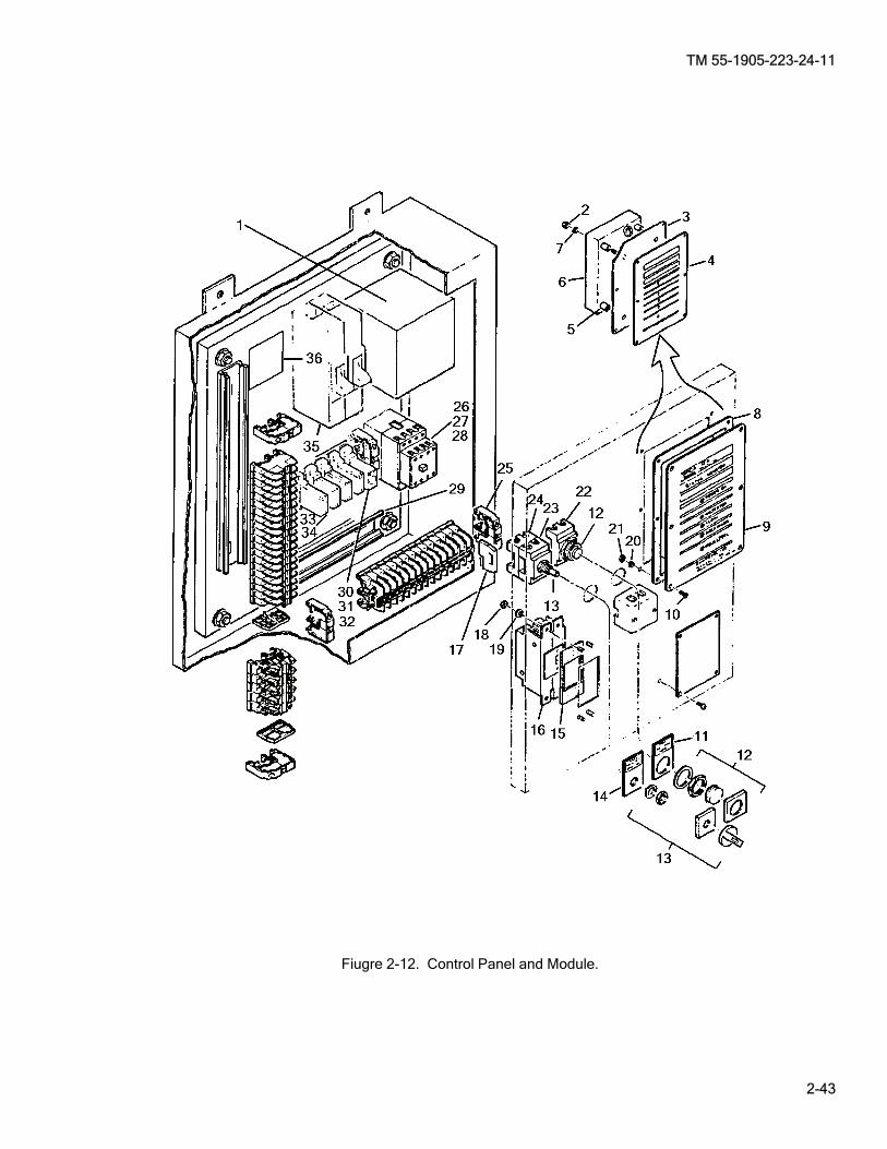
TM 55-1905-223-24-11
2-43
Fiugre 2-12. Control Panel and Module.
TM 55-1905-223-24-11
2-44
2-14. Cable Equipment Routing Assembly. (Figure 2-13) This task covers: a. Inspect, b. Repair, c. Replacement.
________ WARNING
Use extreme caution when checking energized circuits to avoid electrocution. Always ensure affected circuits have been secured, locked out and tagged out. Performing maintenance with circuits energized may result in death or injury to personnel or equipment damage.
NOTE
The equipment routing cable assembly includes six individual electrical cables with their attaching hardware. These cables are for routing the pump motors, level sensors, bleach solenoid control valve, and backwash solenoid to the control panel assembly. Refer to Paragraph 2-12 and Figure 2-5 for disconnecting the individual cables from the control panel assembly.
INSPECT a. Check all cable terminals for tightness in the control panel assembly (Paragraph 2-12). b. Check all cable connections to the flow pump motor, solenoids, and the macerator for tightness. c. Visually check the cable wires for worn insulation. Repair or replace the appropriate cable as required.
Refer to repair or removal and replacement steps in this procedure. REMOVAL (See Figure 2-13 to identify the attaching point of each cable.) a. The procedure for disconnecting the cable from the flow pump and the macerator is the same. See Figure
2-13 for approximate flow pump and macerator locations, and remove the appropriate cable as follows: (1) Loosen the cable connector (6) at the electrical connection box on the pump. (2) Remove the electrical box cover from the pump and disconnect the wires from the pump terminals.
Label all wires so that they can be returned to the same terminals on the pump when installing the new cable.
(3) Remove the appropriate conduit locknut (1) from the cable connector (6) on the inside of the control
panel assembly and withdraw the cable (5) and connector (6) from the control panel assembly. (4) Remove the cable connector (6) from the end of the cable (5) and gasket (2).
INITIAL SETUP Tools Equipment Condition Tool kit, general mechanic's, TM 55-1905-223-10, marine sanitation system secured, 5180-00-699-5273 locked out and tagged (FM 55-502). Tool kit, electrician’s, 5180-00-391-1087 Materials/Parts Tape electrical, Item 16, Section II, Appendix C Warning tag, Item 18, Section II, Appendix C

TM 55-1905-223-24-11
2-45
(5) Disconnect the other end of the cable (5) from TB5 (Figure 2-4 and 2-5) in the control panel assembly.
(a) For the flow pump: TB5-3, TB5-M2 and TB5-T2. (b) For the macerator: TB5-3, TB5-M1 and TB5-T2. (6) Loosen the appropriate conduit locknut (1) on the control panel assembly and withdraw the cable (5). (7) Remove the cable connector (3) from the end of the cable (5) and gasket (2). b. Remove the cable from the backwash solenoid as follows: (1) Loosen the cable connector (4) on the backwash solenoid valve connector (8). (2) Remove the cover plate on the backwash solenoid valve connector (8), label and disconnect the
wiring. Note the locations of each wire on the solenoid terminals so that the new cable can be returned to the same position.
(3) Remove the cable connector (4) and cable (7) from the backwash solenoid valve connector (8). (4) Disconnect the other end of the cable (7) from TB5-1 and TB5-16 (Figure 2-4 and 2-5) in the control
panel assembly. (5) Remove the appropriate conduit locknut (1) on the inside control panel assembly and withdraw the
cable (7) and cable connectors (4) from the control panel assembly. (6) Remove the cable connectors (4) from the end of the cable (7) and gasket (2). REPAIR a. Check electrical wires for worn or frayed insulation, and bent/broken terminals. Check gasket for damage.
Replace or repair as needed. b. Repairs to the equipment routing cable assembly is by replacement of the appropriate cable. REPLACEMENT a. The procedures for replacing the cable on the flow pump and the macerator are the same. See Figure 2-13 for pump locations. Connect the appropriate cable as follows: (1) Remove the cable from the flow pump or the macerator as described in removal procedure step a. (2) Run the cable (5) through the same cable connector (3) on the control panel assembly that the old
cable was removed from. (3) Connect the electrical wires to their proper terminals on the TB5 (Figure 2-4 and 2-5). (a) For the flow pump: TB5-3, TB5-M2 and TB5-T2. (b) For the macerator: TB5-3, TB5-M1 and TB5-T2. (4) Tighten the cable connector (3) at the control panel assembly. (5) Route the cable (5) to the appropriate pump.

TM 55-1905-223-24-11
2-46
(6) Run the pump end of the cable (5) through the connector nut, gasket , and elbow (6). Position the cable (5) in the electrical box cover to the pump and install the locknut (1) to the connector (6) and tighten.
(7) Connect the wires to their proper terminals on the pump. (8) Install the electrical box cover on the pump and tighten the cable connector nut. b. The procedures for replacing the cable on the backwash solenoid (8) are as follows: (1) Run the cable (7) through the same cable connector (4) on the control panel assembly that the old
cable (7) was removed from. (2) Connect the end of the cable (7) to TB5-1 and TB5-16 (Figure 2-4 and 2-5) in the control panel assembly. (3) Tighten the locknut (4) until snug at the control panel assembly. (4) Route the cable (7) to the backwash solenoid (8). (5) Run the solenoid end of the cable through the connector nut, gasket, and connector (5). (6) Connect the wires to their proper terminals on the solenoid. (7) Install the cover plate. c. Restore electrical power, start the unit, and conduct operational check (Paragraph 2-6). d. Operate the MSD (Paragraph 2-6) and check covers, gaskets, piping and hoses for leaks, correct as
necessary. e. Disinfect and remove all spills.

TM 55-1905-223-24-11
2-47
Figure 2-13. Cable Equipment Routing Assembly.
TM 55-1905-223-24-11
2-48
2-15. Screen Assembly and Tank Top Group. (Figure 2-14 and 2-15) This task covers: a. Inspect, b. Service, c. Repair.
________ WARNING
Use extreme caution when checking energized circuits to avoid electrocution. Always ensure affected circuits have been secured, locked out and tagged out. Performing maintenance with circuits energized may result in death or injury to personnel or equipment damage.
________ WARNING
Toxic and flammable vapors are generated in the sewage system. Provide ventilation from outside source before removing treatment tank covers. Avoid open flames and prolonged breathing of fumes.
NOTE
The backwash screen assembly is non-repairable and must be replaced as a complete unit.
INSPECT a. If MSD is equipped with a clear top cover, using a flashlight check screen for blockage. b. If no clear top cover, remove tank cover and use flashlight to check for blockage. SERVICE a. To service the screen, clean with water. REMOVAL a. Remove the treatment tank cover and gasket. Inspect gasket for cracks, tears, and replace if damaged
(3, Figure 2-15).
INITIAL SETUP Tools Equipment Condition Tool kit, general mechanic's, System flushed and drained (Paragraph 2-6). 5180-00-699-5273 TM 55-1905-223-10, marine sanitation system secured, Flash Light, Explosion Proof, locked out and tagged (FM 55-502). 6230-00-264-8261 Materials/Parts Disinfectant, Item 7, Section II, Appendix C Rags, Item 11, Section II, Appendix C Warning tag, Item 18, Section II, Appendix C Cover gasket, P/N 3700073

TM 55-1905-223-24-11
2-49
(1) Remove the ten capscrews (5) and washers (4) from the tank cover. (2) Lift the cover and cover gasket (3) from tank. Discard gasket. b. Remove reduction/retention screen assembly (1) by pulling up on the screen frame. The frame slides
between the guides (2). REPAIR a. Repair is by replacement of screen and gasket. REPLACEMENT a. Insert backwash screen assembly (1, Figure 2-15) into place by sliding it down between the guides (2,
Figure 2-15). b. Install the treatment tank gasket and cover. (1) Ensure gasket surfaces are clean, and install gasket. (2) Position the cover and install ten capscrews and washers. Ensure the gasket stays in position
when installing the cap screws. Tighten capscrews to 31 ft-lb, using the sequence shown in Figure 2-14. c. Restore electrical power, start the unit, and conduct operational check (Paragraph 2-6). d. Operate the MSD (Paragraph 2-6) and check covers, gaskets, piping and hoses for leaks, correct as
necessary. e. Disinfect and remove all spills.
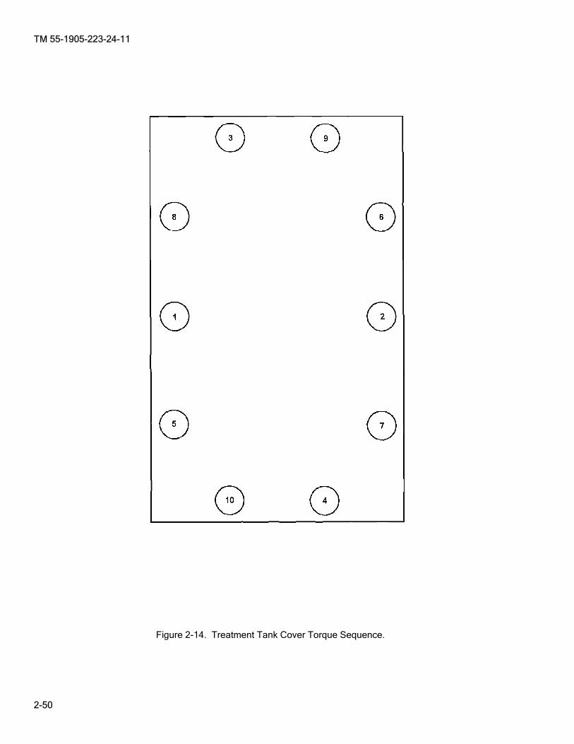
TM 55-1905-223-24-11
2-50
Figure 2-14. Treatment Tank Cover Torque Sequence.
TM 55-1905-223-24-11
2-51
Figure 2-15. Screen Assembly.

TM 55-1905-223-24-11
2-52
2-16. Sedimentation Tank Top Assembly. (Figure 2-16 and 2-17) This task covers: a. Repair.
REMOVAL ________ WARNING
Use extreme caution when checking energized circuits to avoid electrocution. Always ensure affected circuits have been secured, locked out and tagged out. Performing maintenance with circuits energized may result in death or injury to personnel or equipment damage.
NOTE
Hoses (5 and 10, Figure 2-16) will slide on PVC pipe (1 or 9) until butted to the T-fitting, the middle cover must be removed before the inner cover due to space limitations.
a. Loosen the hose clamps (4, Figure 2-16) and slide rubber hoses (5 and 10, Figure 2-16) off pipe (1 or 9, Figure 2-16).
________ WARNING
Toxic and flammable vapors are generated in the sewage system. Provide ventilation from outside source before removing treatment tank covers. Avoid open flames and prolonged breathing of fumes.
NOTE
The cover assembly consists of a plate joined by a common section of PVC vent piping. Remove the cover carefully so as not to crack or damage the piping.
b. Remove nuts (7, Figure 2-16) and washers (6, Figure 2-16). c. Remove cover assembly (2).
INITIAL SETUP Tools Equipment Condition Tool kit, general mechanic's, System flushed and drained (Paragraph 2-6). 5180-00-699-5273 TM 55-1905-223-10, marine sanitation system secured, Torque wrench (in-lb), locked out and tagged (FM 55-502). 5120-01-092-3278 All commodes tagged "Out of Service, Do Not Torque wrench (ft-lb), Operate." 5120-01-125-5190 Materials/Parts Cement, PVC, Item 4, Section II, Appendix C Crocus cloth, fine, Item 6, Section II, Appendix C Disinfectant, Item 7, Section II, Appendix C Solvent/Cleaner, PVC, Item 15, Section II, Appendix C Warning tag, Item 18, Section II, Appendix C Gasket P/N 300021
TM 55-1905-223-24-11
2-53
d. Remove cover gasket (3). REPAIR
NOTE
The PVC piping and joints must be watertight. a. Check the PVC piping for signs of cracks or breaks. Replace PVC piping if damaged or leaking. b. Inspect/replace the gasket (3) if damaged. c. Check float valve assembly (11, Figure 2-16), replace if damaged. REPLACEMENT a. Clean the gasket sealing surfaces on the sedimentation tank and cover assembly (2, Figure 2-16). b. Position the gasket (3, Figure 2-16) on the sedimentation tank. c. Position cover assembly (2, Figure 2-16) onto the appropriate location of the sedimentation tank. d. When positioning the inner cover (2) the end of the vent pipe (9, Figure 2-16) must be placed in the hose (10). Position the cover (2) on the tank and studs. e. Install the sixteen nuts (7, Figure 2-16) and washers (6, Figure 2-16) on the cover (2, Figure 2-16).
Tighten each nut finger tight only. f. Tighten the nuts (7, Figure 2-16) to 31 ft-lbs in the sequence shown in Figure 2-17. g. Tighten the clamps (4, Figure 2-16) on the hose (5, Figure 2-16) to 40 in-lbs. h. Restore electrical power. i. Operate the MSD (Paragraph 2-6) and check covers, gaskets, piping and hoses for leaks, correct as
necessary. k. Disinfect and remove all spills.

TM 55-1905-223-24-11
2-54
Figure 2-16. Sedimentation Tank Cover Assemblies.
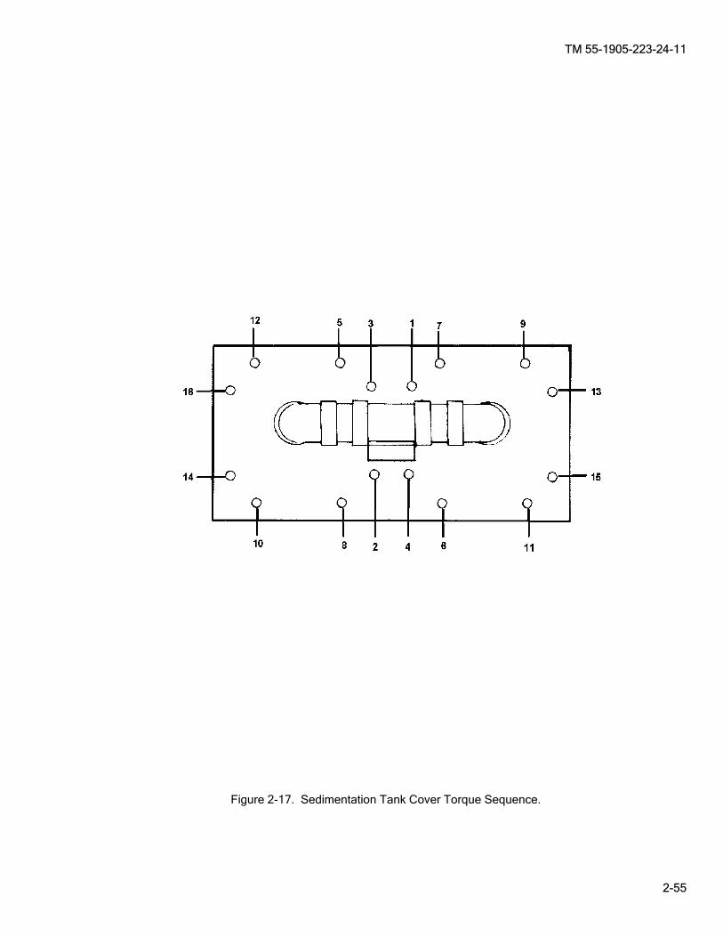
TM 55-1905-223-24-11
2-55
Figure 2-17. Sedimentation Tank Cover Torque Sequence.

TM 55-1905-223-24-11
2-56
2-17. Level Sensor Assembly. (Figure 2-18) This task covers: a. Test, b. Service, c. Repair, d. Replacement.
________ WARNING
Use extreme caution when checking energized circuits to avoid electrocution. Always ensure affected circuits have been secured, locked out and tagged out. Performing maintenance with circuits energized may result in death or injury to personnel or equipment damage.
________ WARNING
Although the system has been drained, personal protective equipment (PPE) must be worn since a small amount of effluent may still be contained within the system. Avoid splashing in eyes when disconnecting fittings.
NOTE
Two different types of Level Sensor Assemblies exist on the MSD. Probes with a single cable design (1, Figure 2-18) and floats with a three cable design (7).
TEST a. If the MSD system does not operate in the AUTO mode, accomplish the following: (1) Place the mode switch on the control panel assembly in the CONT mode (Paragraph 2-6). (2) If the MSD system operates properly in the CONT mode, either the level sensors connections
(proceed to step c.) or the microprocessor in the control panel are defective (Paragraph 2-13).
INITIAL SETUP Tools Equipment Condition Tool kit, general mechanic's, System flushed and drained (Paragraph 2-6). 5180-00-699-5273 TM 55-1905-223-10, marine sanitation system secured, Tool kit, electrician’s, locked out and tagged (FM 55-502). 5180-00-391-1087 Multimeter, 6625-01-265-6000 Materials/Parts Brush, non metallic, Item 3, Section II, Appendix C Gloves, chemical, Item 8, Section II, Appendix C Goggles, Item 9, Section II, Appendix C Soap, Item 14, Section II, Appendix C Warning tag, Item 18, Section II, Appendix C Installation Instructions, P/N INS3054 Gasket, level sensor P/N 3600093 Level sensor assembly (new) P/N 3700168 Level sensor assembly Retrofit Kit P/N 3999478

TM 55-1905-223-24-11
2-57
________ WARNING
Turn all electrical power OFF to the MSD system to avoid personal injury. Lockout/Tagout MSD system according to vessel SOP.
b. Turn OFF all electrical power to the MSD system (Paragraph 2-6). c. Check the connections 10 through 12, 14 and 15 on TB2 and TB3 (Figure 2-5, Sheet 1) in the control
panel assembly for tightness. Tighten connections. d. Conduct startup and operational check, verify proper operation (Paragraph 2-6). e. If the MSD still operates only in the CONT mode, accomplish the following:
________ WARNING
Turn all electrical power OFF to the MSD system to avoid personal injury. Lockout/Tagout MSD system according to vessel SOP.
(1) Turn all electrical power OFF to the sanitary unit.
________ WARNING
Toxic and flammable vapors are generated in the sewage system. Provide ventilation from outside source before removing covers, drain plugs, hoses, and fittings. Avoid open flames and prolonged breathing of fumes.
(2) Drain and flush the MSD system (Paragraph 2-6). (3) Remove the Level Sensor Assembly utilizing removal steps in this task. (4) Check the level sensor assembly for cracks, breaks, or other damage. Check gasket for damage
and wear. Replace the level sensor assembly if damaged.
NOTE
The single cable level sensor (1, Figure 2-18) is obsolete. Service is only applicable to the probes with a single cable design. If after servicing the probes does not correct the problem, replacement of the level sensor assembly is required utilizing the new Retro Fit kit.
SERVICE If the level sensor assembly probes (5) are not damaged, accomplish the following: a. Refer to removal steps a. and b. in this task. b. Clean the tips of the sensing probes with a soft bristle non metallic brush and mild soap. Be careful not to
bend or damage the probes during cleaning. c. Install the level sensor assembly utilizing replacement steps d. through g. in this task. d. If the MSD still fails to operate properly, replace the level sensor assembly.

TM 55-1905-223-24-11
2-58
NOTE
If replacement of the probes with a single cable design is required, retrofit kit P/N 3999478 consists of all necessary components and removal/installation instructions.
REMOVAL To remove the level sensor assembly, see Figure 2-18 and proceed as follows: a. Remove six nuts (2) and six washers (3) from level sensor assembly (1 or 7). b. Remove level sensor assembly (1 or 7) and gasket (6) from tank top cover by lifting up and out. c. Label and disconnect wires 10 through 12, 14 and 15 on TB2 and TB3 (Figure 2-5, Sheet 1) in the control panel. d. Check for continuity of each float (8) using a multimeter and raising and lowering the float. Verify the
contact open and closes for each float to determine the appropriate float that needs to be replaced. e. Loosen the appropriate conduit lock nut(s) (11, Figure 2-18) located on the side of the control panel and
remove cable(s) for the appropriate float (8) by pulling. f. Loosen the conduit locknut (10) on the level sensor assembly cover (4), remove cable clamp (9) from float (8) and retain. g. Remove the appropriate cable(s) by pulling.
NOTE
If replacement of the probes with a single cable design is required, retrofit kit P/N 3999478 consists of all necessary components and removal/installation instructions.
REPAIR Repair of the Level Sensor Assembly is by replacement of floats and gaskets. Refer to removal and replacement sections in this task
________ WARNING
Although the system has been drained, personal protective equipment (PPE) must be worn since a small amount of effluent may still be contained within the system. Avoid splashing in eyes when disconnecting fittings.
NOTE
If replacement of the probes with a single cable design is required, retrofit kit P/N 3999478 consists of all necessary components and removal/installation instructions.
REPLACEMENT To replace the level sensor assembly, see Figure 2-18 and proceed as follows: a. Install new float by threading cable through conduit locknut (10) and thread the running end of the cable
through the appropriate conduit locknut (11) on the control panel and connect the float (8) to the clamp (9).

TM 55-1905-223-24-11
2-59
b. Tighten conduit locknuts (10 and 11, Figure 2-18). c. Connect the wires 10 through 12, 14 and 15 on TB2 and TB3 (Figure 2-5) on the control panel. d. Install cover (4) and gasket (6) with six nuts (2) and six washers (3) to the tank top cover (Figure 2-18). e. Restore electrical power, start the unit, and conduct operational check (Paragraph 2-6). f. Operate the MSD (Paragraph 2-6) and check covers, gaskets, piping and hoses for leaks, correct as
necessary. g. Disinfect and remove all spills.
Figure 2-18. Level Sensor Assembly.
TM 55-1905-223-24-11
2-60
2-18. Macerator Pump Assembly. (Figure 2-19) This task covers: a. Inspect b. Test, c. Repair, d. Replacement.
INSPECT Inspection of the macerator pump assembly is accomplished through Preventive Maintenance Checks and Services (PMCS, TM 55-1905-223-10). TEST
________ WARNING
Use extreme caution when checking energized circuits to avoid electrocution. Always ensure affected circuits have been secured, locked out and tagged out. Performing maintenance with circuits energized may result in death or injury to personnel or equipment damage. SHOCK HAZARD. Ensure all electrical power to the unit is OFF to prevent injury to personnel. Lockout/Tagout MSD system according to vessel SOP. Although the system has been drained, personal protective equipment (PPE) must be worn since a small amount of effluent may still be contained within the system. Avoid splashing in eyes when disconnecting fittings.
a. If the macerator pump assembly does not operate, conduct the following checks and test: (1) Open the external sewage valves and backwash gate valve while conducting test procedure.
INITIAL SETUP Tools Equipment Condition Tool kit, general mechanic's, System flushed and drained (Paragraph 2-6). 5180-00-699-5273 TM 55-1905-223-10, marine sanitation system secured, Tool kit, electrician’s, locked out and tagged (FM 55-502). 5180-00-391-1087 Torque wrench 30-200 in-lbs, 5120-01-092-3278 Wrench, Chain, 5120-01-018-3203 Multimeter, 6625-01-265-6000 Materials/Parts Disinfectant, Item 7, Section II, Appendix C Oil, Item 10, Section II, Appendix C Rags, Item 11, Section II, Appendix C Tape, Teflon, Item 17, Section II, Appendix C Warning tag, Item 18, Section II, Appendix C Container, Closeable, 1-gallon (to catch runoff)
TM 55-1905-223-24-11
2-61
(2) With the electrical power OFF, open the control panel and check the pump leads on the circuit board for breaks or loose connections. See Figure 2-5, Sheet 1 for terminal identification. Tighten connections or replace leads as required.
(3) Turn electrical power ON and place the MSD in the CONT mode (Paragraph 2-6).
________ WARNING
Under no circumstances should repair or adjustment of energized equipment be attempted alone. The immediate presence of someone capable of rendering aid is required. Before making adjustments, be sure to protect against grounding. If possible, adjustments should be made with one hand, with the other hand free and clear of equipment. Even when power has been removed from equipment circuits, dangerous potentials may still exist due to retention of charges by capacitors. Circuits must be grounded and all capacitors discharged prior to attempting repairs.
(4) Use a multimeter and test for proper voltage at TB5 across the terminals of M1 and T2 (Figure 2-5,
Sheet 1) in the control panel. (a) The voltage should be 220/230 VAC. (b) If there is no voltage at the terminals, test control panel components (Paragraph 2-13). (c) If the correct voltage reading is obtained on the terminals, go to the next step. (5) Turn the electrical power OFF. Lockout/Tagout MSD system according to vessel SOP. (6) Remove the electrical box cover (3) on the inoperative pump to reveal the cable connections
(Paragraph 2-14). Check for broken leads or loose connections. Tighten connection or replace leads as required.
(a) Position the cover away from possible contact with the electrical connections. (b) Turn the electrical power ON and place the MSD system in a CONT mode (Paragraph 2-6). (c) Use a multimeter and check the voltage on the pump terminals. (d) If there is no voltage available, replace the electrical cable (Paragraph 2-14). (e) If the proper voltage is available (220/230 VAC), and pump still does not operate, the pump is
defective. b. Replace the pump system. Refer to the removal and replacement steps of this procedure.
________ WARNING
Although the system has been drained, personal protective equipment (PPE) must be worn since a small amount of effluent may still be contained within the system. Avoid splashing in eyes when disconnecting fittings.
REPAIR Complete repair to the macerator is accomplished by DS maintenance level (Paragraph 3-8). In the event of a macerator jam, clear jam as follows: a. Perform screen assembly and tank top removal procedure, Paragraph 2-15. b. Remove cap (11, Figure 2-19) using a chain wrench.

TM 55-1905-223-24-11
2-62
c. Use socket with extension on nut (7, Figure 3-1) and turn in a clockwise direction. d. Remove the object(s) which created the jam. e. If the jam cannot be cleared in this manner, the macerator must be disassembled and the object(s)
removed. Refer to Intermediate Direct Support maintenance instructions for disassembly/repair procedures.
REMOVAL See Figure 2-19 and proceed as follows:
________ WARNING
Use extreme caution when checking energized circuits to avoid electrocution. Always ensure affected circuits have been secured, locked out and tagged out. Performing maintenance with circuits energized may result in death or injury to personnel or equipment damage.
NOTE
If access to the side of the MSD is not available to remove macerator, the flow pump must be removed (Paragraph 2-19) to gain access to macerator.
a. Label and disconnect all wiring at macerator (2) (Paragraph 2-14, Removal steps a.1 through a.3). b. Place a support under macerator (2).
________ WARNING
Toxic and flammable vapors are generated in the sewage system. Provide ventilation from outside source before removing covers, hoses (5 and 9), drain plugs, and fittings. Avoid open flames and prolonged breathing of fumes. Although the system has been drained, personal protective equipment (PPE) must be worn since a small amount of effluent may still be contained within the macerator (2). A suitable container must be used to catch remaining effluent. Avoid splashing in eyes when disconnecting hoses. If there is no support under the macerator as it is removed, the macerator could be dropped accidentally. The housing at the bottom of the macerator could be damaged or personnel could be injured.
c. Disconnect discharge elbow (6) by removing screws (8). Remove and inspect gasket (7) and retain. (1) Hold a container under the connection to catch effluent runoff and remove the elbow (6) by
loosening screws (8) to drain the disposer pump and piping. Remove screws (8) and gasket (7). (2) Loosen clamps (9) on the hose (10), and remove from nipple. d. Remove hose (10) and hose clamps (9). e. Remove macerator (2) by removing attaching screws (4) and washers (5). f. Remove and inspect gasket (2, Figure 3-1) and retain.
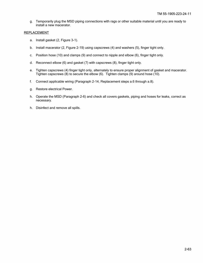
TM 55-1905-223-24-11
2-63
g. Temporarily plug the MSD piping connections with rags or other suitable material until you are ready to install a new macerator.
REPLACEMENT a. Install gasket (2, Figure 3-1). b. Install macerator (2, Figure 2-19) using capscrews (4) and washers (5), finger tight only. c. Position hose (10) and clamps (9) and connect to nipple and elbow (6), finger tight only. d. Reconnect elbow (6) and gasket (7) with capscrews (8), finger tight only. e. Tighten capscrews (4) finger tight only, alternately to ensure proper alignment of gasket and macerator.
Tighten capscrews (8) to secure the elbow (6). Tighten clamps (9) around hose (10). f. Connect applicable wiring (Paragraph 2-14, Replacement steps a.6 through a.8). g. Restore electrical Power. h. Operate the MSD (Paragraph 2-6) and check all covers gaskets, piping and hoses for leaks, correct as
necessary. h. Disinfect and remove all spills.
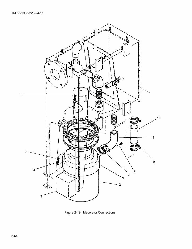
TM 55-1905-223-24-11
2-64
Figure 2-19. Macerator Connections.

TM 55-1905-223-24-11
2-65
2-19. Flow Pump Assembly. (Figures 2-20, 2-21 and 2-22) This task covers: a. Inspect, b. Test, c. Adjust, d. Repair, e. Replacement.
INSPECT Inspection of the flow pump assembly is accomplished through PMCS, Table 2-4 and maintenance procedures.
________ WARNING
Use extreme caution when checking energized circuits to avoid electrocution. Always ensure affected circuits have been secured, locked out and tagged out. Performing maintenance with circuits energized may result in death or injury to personnel or equipment damage.
TEST
NOTE
Open the external sewage valves and backwash gate valve while conducting test procedure.
a. If the flow pump system does not operate, conduct the following checks and test: (1) With the electrical power OFF, open the control panel and check the pump leads on the circuit
board for breaks or loose connections. See Figure 2-5, Sheet 1 for terminal identification. Tighten connections or replace leads as required.
(2) Turn electrical power ON and place the MSD in the CONT mode (Paragraph 2-6).
INITIAL SETUP Tools Equipment Condition Tool kit, general mechanic's, System flushed and drained (Paragraph 2-6). 5180-00-699-5273 TM 55-1905-223-10, marine sanitation system secured, Tool kit, electrician’s, locked out and tagged (FM 55-502). 5180-00-391-1087 Multimeter, 6625-01-265-6000 Torque wrench 30-200 in-lbs, 5120-01-092-3278 Torque wrench 30-200 ft-lbs, 5120-01-125-5190 Puller, Mechanical, 5120-00-499-1489 Materials/Parts Bolt, 5/16 x 2 1/2, Inch NCT, Item 2, Section II Appendix C
Disinfectant, Item 7, Section II, Appendix C Rags, Item 11, Section II, Appendix C Tape, Teflon, Item 17, Section II, Appendix C Warning tag, Item 18, Section II, Appendix C Shallow pan Type container (to catch runoff)

TM 55-1905-223-24-11
2-66
________ WARNING
Under no circumstances should repair or adjustment of energized equipment be attempted alone. The immediate presence of someone capable of rendering aid is required. Before making adjustments, be sure to protect against grounding. If possible, adjustments should be made with one hand, with the other hand free and clear of equipment. Even when power has been removed from equipment circuits, dangerous potentials may still exist due to retention of charges by capacitors. Circuits must be grounded and all capacitors discharged prior to attempting repairs.
(3) Use a multimeter and test for proper voltage across the terminals of M2 and T2 (Figures 2-4 and 2-5) in the control panel on TB5. (a) The voltage should be 220/230 VAC. (b) If there is no voltage at the terminals, test control panel components (Paragraph 2-13). (c) If the correct voltage reading is obtained on the terminals, go to the next step (4).
________ WARNING
Use extreme caution when checking energized circuits to avoid electrocution. Always ensure affected circuits have been secured, locked out and tagged out. Performing maintenance with circuits energized may result in death or injury to personnel or equipment damage.
(4) Turn the electrical power OFF. Lockout/Tagout MSD system according to vessel SOP. (5) Remove the electrical box cover on the inoperative pump to reveal the cable connections
(Paragraph 2-14). Check for broken leads or loose connections. Tighten connection or replace leads as required.
(a) Position the cover away from possible contact with the electrical connections. (b) Turn the electrical power ON and place the MSD system in a CONT mode (Paragraph 2-6). (c) Use a multimeter and check the voltage on the pump terminals. (d) If there is no voltage available, replace the electrical cable (Paragraph 2-14). (e) If the proper voltage is available (220/230 VAC), and pump still does not operate, the pump is
defective. b. Replace the pump system. Refer to the removal and replacement steps of this procedure. ADJUST Adjustment to the flow pump is accomplished by adjusting the impeller as follows:
________ WARNING
Do not attempt pump adjustment when pump is running to avoid personal injury.
a. Loosen slide lock (2, Figure 2-20) and rotate away from adjusting screw (1). b. Using a spanner wrench (3) or appropriate punch turn adjusting screw (1). At the same time, rotate shaft
back and forth with a common nail (5) or other object placed through the hole provided (4).

TM 55-1905-223-24-11
2-67
c. Rotate adjusting screw (1) in a clockwise direction (6). A drag will be felt as the impeller comes into contact with raceway. At this point, make a mark (7) on pump frame and adjusting screw (1) (across one of the spanner wrench holes).
d. Rotate adjusting screw (1) in the opposite direction (counterclockwise) to back off impeller until no drag is
felt. Make a second mark (8) on the pump frame inline with the adjusting screw mark. The correct clearance may be obtained by moving the adjusting screw approximately one half the distance between mark (7) and mark (8).
e. Lock adjusting screw in place by inserting slide lock (2) tab in the nearest spanner wrench hole of the
adjusting screw (1) and tighten lock (2) screw. f. Place power switch in ON position and run pump. If pump seems to labor unduly when coming up to
pressure, a slight additional adjustment must be made to increase the clearance between the impeller and raceway.
REMOVAL
________ WARNING
Toxic and flammable vapors are generated in the sewage system. Provide ventilation from outside source before removing covers, hoses, drain plugs, and fittings. Avoid open flames and prolonged breathing of fumes.
________ WARNING
Use extreme caution when checking energized circuits to avoid electrocution. Always ensure affected circuits have been secured, locked out and tagged out. Performing maintenance with circuits energized may result in death or injury to personnel or equipment damage.
See Figure 2-21 and proceed as follows: a. Secure inlet valve (5) and outlet valve (4). b. Label and disconnect wiring in connection box (12) on pump (Paragraph 2-14, Removal step a.1 through a.3). c. Disconnect pressure sensor line from pump. d. Remove pump/motor assembly (13) by removing four screws (11), four washers (9) and four nuts (10) and
remove appropriate hoses and pipes to facilitate pump (13) removal.
REPAIR
NOTE
Flush the pump with water and disinfectant before disposal or further handling.
Cover and seal pump openings with suitable material prior to disposal.
Repair is by replacement of Flow Pump assembly, damaged or worn components (Figure 2-22).

TM 55-1905-223-24-11
2-68
________ WARNING
Although the system has been drained, personal protective equipment (PPE) must be worn since a small amount of effluent may still be contained within the pump. Avoid splashing in eyes when disconnecting hoses.
a. Remove plugs (1 and 2) to drain remaining liquid. b. Remove case (3) by removing screws (14). c. Remove gasket (4) and sleeve (5). Remove raceway (7) by removing screws (6). d. Hold the shaft with locking pliers and remove nut (8). e. Remove impeller (9): (1) Insert two 5/16 x 2-1/2 inch NCT bolts into threaded holes on impeller. (2) Apply an H-type impeller puller on the shaft and attach to the bolts. Hold shaft with locking pliers
and remove impeller. f. Remove key (10) and rotating portions of seal (11). g. Remove screw lock (13) by removing screw (12). h. Remove frame (16) by removing screws (15). Remove stationary portion of seal (11). Remove washer (17). i. Place a small screwdriver in hole of adjusting screw (18). Use a large screwdriver as a lever against the
shaft to turn the adjusting screw in a clockwise direction to remove. j. Inspect and replace damaged or worn components. k. Install adjusting screw (18) by turning in a counterclockwise direction by hand.
CAUTION Care should be observed that cleansing material and oil are free of foreign particles.
Do not use grease or allow grease on the sealing surfaces.
Avoid skin contact with sealing surface to prevent etching of the seal. l. Install stationary portion of seal (11) into frame (16). m. Install washer (17) and frame (16); secure with screws (15). n. Install rotating portions of seal (11) and key (10). o. Being careful not damage impeller (9) face use a large socket to drive the impeller until fully seated onto
shaft. p. While holding shaft with locking pliers install nut (8). q. Install raceway (7) and secure with screws (6). Install gasket (4) and sleeve (5). r. Install case (3) and secure with screws (14).

TM 55-1905-223-24-11
2-69
s. Install plugs (1 and 2). t. Perform adjustment procedure contained in this paragraph. u. Install screw lock (13) and secure with screw (12). REPLACEMENT a. Install pump assembly (13, Figure 2-21) using screws (11), washers (9) and nuts (10). b. Connect applicable wiring in connection box (12) (Paragraph 2-14, Replacement steps a.6 through a.8). c. Apply Teflon pipe thread lubricant to the pipe threads.
CAUTION
Do not over tighten. PVC fittings may crack. d. Screw the connections into their proper locations. Tighten the connections until snug. e. Ensure the connections are aligned with their respective hose connections. f. Install the inlet hose (7) and tighten the clamps (6 and 8) to 40 in-lbs. g. Install the discharge hose (2) and tighten the clamps (1 and 3) to 40 in-lbs. h. Open the inlet valve (5) and outlet valve (4). i. Restore electrical power. j. Operate the MSD (Paragraph 2-6) and check all covers, gaskets, piping and hoses for leaks, correct as
necessary. k. Disinfect and remove all spills.

TM 55-1905-223-24-11
2-70
Figure 2-20. Flow Pump Impeller Adjustment.

TM 55-1905-223-24-11
2-71
Figure 2-21. Flow Pump Connections.

TM 55-1905-223-24-11
2-72
Figure 2-22. Flow Pump Assembly.
TM 55-1905-223-24-11
2-73
2-20. Backwash Piping Assembly Group. (Figure 2-23) This task covers: a. Inspect, b. Repair.
INSPECT Inspection of the backwash piping assembly group is accomplished through Preventive Maintenance Checks and Services (PMCS, TM 55-1905-223-10) and maintenance procedures. REMOVAL
________ WARNING
Use extreme caution when checking energized circuits to avoid electrocution. Always ensure affected circuits have been secured, locked out and tagged out. Performing maintenance with circuits energized may result in death or injury to personnel or equipment damage.
a. Turn ASW supply off, b. Remove the gate valve (15, Figure 2-23): (1) Disconnect the water supply line at the valve inlet coupling (20, Figure 2-23). (2) Remove the gate valve (15) from the pipe nipple. (3) Remove coupling half (20) and retain. c. Remove the dial indicating pressure gauge (28, Figure 2-23): (1) Unscrew gauge (28) from bushing (26). Remove the gauge by turning it counterclockwise.
INITIAL SETUP Tools Equipment Condition Tool kit, general mechanic's, System flushed and drained (Paragraph 2-6). 5180-00-699-5273 TM 55-1905-223-10, marine sanitation system secured, Tool kit, electrician's, locked out and tagged (FM 55-502). 5180-00-391-1087 Torque wrench 30-200 (in-lb), 5120-01-092-3278 Materials/Parts Cement, PVC glue, Item 4, Section II, Appendix C Clamp, tubing Item 5, Section II, Appendix C Disinfectant, Item 7, Section II, Appendix C Rags, wiping, Item 11, Section II, Appendix C Solvent/Cleaner, PVC Item 15, Section II, Appendix C Tape, Teflon, Item 17, Section II, Appendix C Warning tags, Item 18, Section II, Appendix C Gasket, P/N 3500138 Container, Closeable, 1 qt (to catch bleach or effluent runoff)
TM 55-1905-223-24-11
2-74
d. Remove the backwash solenoid valve (32): (1) Loosen the cable connector (4, Figure 2-13) on the backwash solenoid valve connector (8, Figure 2-13). (2) Remove the cover plate on backwash solenoid valve connector (8, Figure 2-13), label and
disconnect the wiring. Note the locations of each wire on the solenoid terminals so that the new cable can be returned to the same position.
(3) Unscrew bushing (30, Figure 2-23) on bottom of backwash solenoid valve (32). (4) Unscrew solenoid valve (32) from upper bushing (30) and remove. e. Remove the discharge check valve (17): (1) Remove hose clamps (9) and hose (10) then check valve (17) from nipple (18). (2) The lower section of piping (9, 11, 12, 13, 14 and 16) can be disconnected when the check valve is
removed. ________ WARNING
CHEMICAL HAZARD. Personal protective equipment (PPE) must be worn to avoid contact with skin and splashing in eyes. Avoid prolonged breathing of fumes.
REPAIR a. Repair to the piping group is by replacement of the following components: (1) Backwash solenoid valve. (2) Gate valve. (3) Pressure gauge. (4) Discharge check valve. b. Refer to the removal and replacement steps of this procedure. REPLACEMENT
CAUTION
Do not over tighten. PVC fittings may crack.
NOTE
Apply Teflon Tape to all threaded fittings. a. Replace the ball check valve (17, Figure 2-23). (1) Replace lower section of piping (9, 11, 12, 13, 14 and 16). (2) Replace check valve (17) onto upper nipple (18) and replace reconnect lower nipple (16).

TM 55-1905-223-24-11
2-75
(3) Replace hose (10) and hose clamps (9) onto lower nipple. b. Replace the backwash water solenoid valve (32, Figure 2-23). (1) Screw backwash solenoid valve (32) onto upper bushing (30). (2) Screw lower bushing (30) on bottom of backwash solenoid valve (32). (3) Re-connect the wiring to the backwash solenoid valve and replace the cover plate to the backwash
solenoid valve connector (10, Figure 2-13). (4) Tighten the cable connector (5 Figure 2-13) on the backwash solenoid valve connector (10, Figure
2-13). c. Replace the dial indicating pressure gauge (28, Figure 2-23). (1) Apply Teflon Tape to the threads of the new gauge (28). (2) Install the gauge into the pipe bushing. Turn the gauge clockwise to install. (3) Align the gauge and secure the locknut at the base of the gauge and hand tighten. d. Replace the gate valve (15, Figure 2-23). (1) Apply Teflon Tape to the connections, and install the gate valve (15) to the coupling half (20) and
the valve inlet coupling. (2) The water inlet is now connected to the sanitary unit. Close the valve by turning the handle fully
clockwise. (3) Open the external water supply valve to the sanitary unit. Check for leaks at the inlet of the gate
valve (15) and correct as required. (4) Open the gate valve (15). e. Open the bleach metering valve. f. Restore electrical power, start the unit, and conduct operational check (Paragraph 2-6). g. Operate the MSD paragraph 2-6 and check covers, gaskets, piping and hoses for leaks, correct as
necessary. h. Disinfect and remove all spills.

TM 55-1905-223-24-11
2-76
Figure 2-23. Backwash Piping Assembly Group.
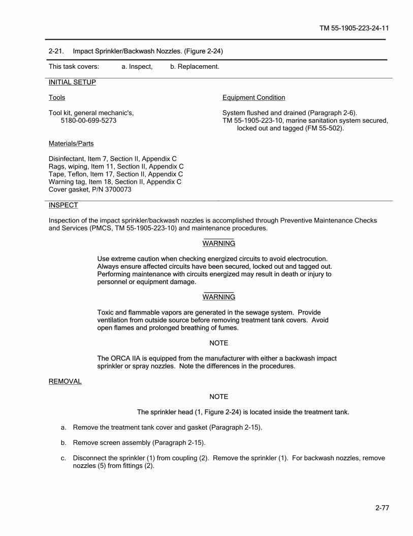
TM 55-1905-223-24-11
2-77
2-21. Impact Sprinkler/Backwash Nozzles. (Figure 2-24) This task covers: a. Inspect, b. Replacement.
INSPECT Inspection of the impact sprinkler/backwash nozzles is accomplished through Preventive Maintenance Checks and Services (PMCS, TM 55-1905-223-10) and maintenance procedures.
________ WARNING
Use extreme caution when checking energized circuits to avoid electrocution. Always ensure affected circuits have been secured, locked out and tagged out. Performing maintenance with circuits energized may result in death or injury to personnel or equipment damage.
________ WARNING
Toxic and flammable vapors are generated in the sewage system. Provide ventilation from outside source before removing treatment tank covers. Avoid open flames and prolonged breathing of fumes.
NOTE
The ORCA IIA is equipped from the manufacturer with either a backwash impact sprinkler or spray nozzles. Note the differences in the procedures.
REMOVAL
NOTE
The sprinkler head (1, Figure 2-24) is located inside the treatment tank. a. Remove the treatment tank cover and gasket (Paragraph 2-15). b. Remove screen assembly (Paragraph 2-15). c. Disconnect the sprinkler (1) from coupling (2). Remove the sprinkler (1). For backwash nozzles, remove
nozzles (5) from fittings (2).
INITIAL SETUP Tools Equipment Condition Tool kit, general mechanic's, System flushed and drained (Paragraph 2-6). 5180-00-699-5273 TM 55-1905-223-10, marine sanitation system secured, locked out and tagged (FM 55-502). Materials/Parts Disinfectant, Item 7, Section II, Appendix C Rags, wiping, Item 11, Section II, Appendix C Tape, Teflon, Item 17, Section II, Appendix C Warning tag, Item 18, Section II, Appendix C Cover gasket, P/N 3700073

TM 55-1905-223-24-11
2-78
REPLACEMENT NOTE
Apply Teflon Tape to all threaded fittings.
a. Impact Sprinkler: (1) Apply Teflon Tape to the pipe threads on the new sprinkler (1). (2) Connect the sprinkler (1) to coupling (2). (3) Ensure the sprinkler (1) is properly adjusted towards the retention/reduction screen (3) when
connecting the coupling.
NOTE
Apply Teflon Tape to all threaded fittings. b. Backwash Nozzles: (1) Apply Teflon Tape to the pipe threads on the new nozzles (5). (2) Thread nozzles (5) into fitting (2) of spray pipe (4). Tighten until resistance is felt, do not over
tighten. (3) Install the screen assembly (Paragraph 2-15). (4) Install the treatment tank cover and gasket (Paragraph 2-15). (5) Restore electrical power. (6) Operate the MSD paragraph 2-6 and check covers, gaskets, piping and hoses for leaks, correct as
necessary. (7) Disinfect and remove all spills.
NOTE
The backwash pressure gauge is located on the incoming backwash water line to the unit (Figure 1-1).
(8) Operate the unit (Paragraph 2-6) and adjust the backwash water pressure to 40 ± 5 psi.
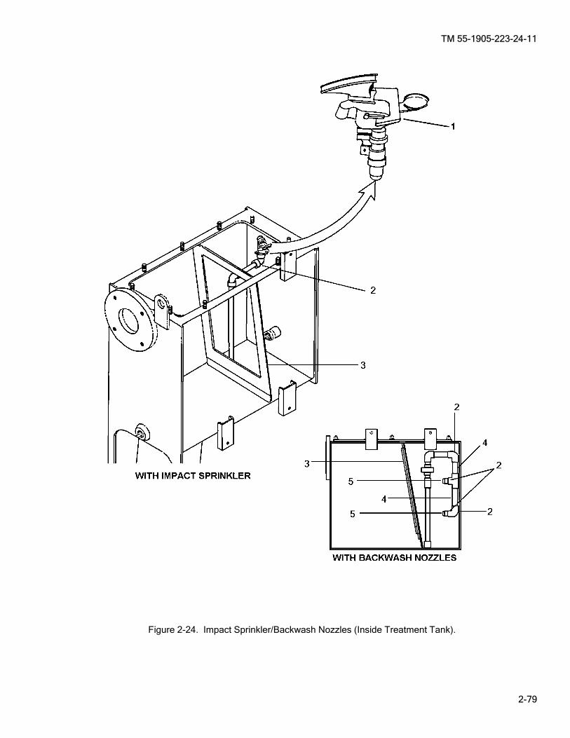
TM 55-1905-223-24-11
2-79
Figure 2-24. Impact Sprinkler/Backwash Nozzles (Inside Treatment Tank).
TM 55-1905-223-24-11
2-80
2-22. Flow Piping Assembly Group. (Figures 2-16 and 2-25) This task covers: a. Inspect, b. Repair. INITIAL SETUP Tools Equipment Condition Tool kit, general mechanic's, System flushed and drained (Paragraph 2-6). 5180-00-699-5273 TM 55-1905-223-10, marine sanitation system
secured, locked out and tagged (FM 55-502). Tool kit, electricians, 5180-00-391-1087 Materials/Parts Clamp, tubing Item 5, Section II, Appendix C Tape, Teflon, Item 17, Section II, Appendix C Warning tags, Item 18, Section II, Appendix C Container, 1 qt (to catch bleach or effluent runoff) INSPECT Inspection of the flow piping assembly group is accomplished through Preventive Maintenance Checks and Services (PMCS, TM 55-1905-223-10) and maintenance procedures.
________ WARNING
Use extreme caution when checking energized circuits to avoid electrocution. Always ensure affected circuits have been secured, locked out and tagged out. Performing maintenance with circuits energized may result in death or injury to personnel or equipment damage.
________ WARNING
Although the system has been drained, personal protective equipment (PPE) must be worn since a small amount of effluent may still be contained within the piping. Avoid splashing in eyes when disconnecting fittings.
REMOVAL a. Removal of the Flow Control Valve (Figure 2-25); proceed as follows: (1) Place container under pipe plug (7) to catch remaining bleach or effluent. (2) Remove pipe plug (7) and allow complete draining of piping system. (3) Loosen two hose clamps (8) from non metallic hose (15) and remove hose. (4) Disconnect nipple pipe (3) from flow control valve (16). (5) Disconnect flow control valve (16) from pipe bushing (17). b. Removal of the piping assembly (Figure 2-25) proceed as follows:
TM 55-1905-223-24-11
2-81
(1) The upper section of piping (17 18, 19, 20 and 21) can be disconnected after the flow control valve (16) is removed. (2) The lower section of piping (14, 4, 13, 6, 12, 11, 3, 5 and 10) can be disconnected after removal of
the two hose clamps (8) from the applicable non metallic hoses (15 or 9). (3) Disconnecting pipe (1) and elbow (2) can be accomplished after removal of sedimentation tank top
cover (2, Figure 2-16, Paragraph 2-16).
CAUTION
Do not over tighten. PVC fittings may crack.
NOTE
Apply Teflon Tape to all threaded fittings.
REPAIR Repair is by replacement of the Flow Control Valve, damaged or worn associated piping (Figure 2-25): a. To repair the flow control valve (16): (1) Remove flow control valve as described in removal step a. (2) Install new flow control valve as described in replacement step a. b. To repair associated pipe fittings (17, 18, 19, 20, 21, 14, 13, 6, 12, 11, 3, 5, 10, 1 and 2): (1) Remove applicable associated pipe fittings as describe in removal step b. (2) Install new applicable pipe fitting as described in replacement step b.
CAUTION
Do not over tighten. PVC fittings may crack.
NOTE
Apply Teflon Tape to all threaded fittings.
REPLACEMENT a. To replace the Flow Control Valve (Figure 2-25) proceed as follows: (1) Connect flow control valve (16) to pipe bushing (17). (2) Re-connect nipple pipe (3) to flow control valve (16). (3) Re-connect non metallic hose (15) to nipple and pipe (14). (4) Move hose clamps (8) over hose and tighten. (5) Replace pipe plug (7). b. To replace the upper piping assembly (Figure 2-25) proceed as follows: (1) Re-connect the piping (17, 18, 19, 20 and 21).
TM 55-1905-223-24-11
2-82
(2) The applicable lower section of piping (14, 4, 13, 6, 12, 11, 3, 5 and 10) can be reconnected and reconnect the two hose clamps (8) to the applicable non metallic hoses (15 or 9).
(3) Reconnect pipe (1) and elbow (2) and replace sedimentation tank top cover (Figure 2-16, Paragraph 2-16). c. Restore electrical power. Operate the MSD (Paragraph 2-6) and check covers, gaskets, piping and hoses
for leaks, correct as necessary.
TM 55-1905-223-24-11
2-83
Figure 2-25. Flow Piping Assembly Group.
TM 55-1905-223-24-11
2-84
2-23. Bleach Tank Assembly. (Figure 2-26 and 2-11) This task covers: a. Inspect, b. Service, c. Replacement.
INSPECT Inspection of the bleach tank assembly is accomplished through Preventive Maintenance Checks and Services (PMCS, TM 55-1905-223-10) and maintenance procedures.
SERVICE Service of the bleach tank is accomplished through Preventive Maintenance Checks and Services (PMCS, TM 55-1905-223-10) and operating procedure Paragraph 2-6.
________ WARNING
Avoid splashing bleach in eyes when disconnecting lines.
NOTE
The bleach tank is located separately from the sanitary unit. A 1/4–inch gravity feed line is attached from the tank to the metering valve (19, Figure 2-11) on the unit.
REMOVAL To remove Bleach Tank Assembly (Figure 2-26), proceed as follows: a. Close bleach tank isolation valve. b. Disconnect the bleach line (21, Figure 2-11). (1) Loosen tube to hose adapter (20, Figure 2-11). (2) And disconnect from metering valve (19, Figure 2-11). c. Place metering valve end of bleach line into closeable container. Open Bleach tank isolation valve to
drain bleach from tank. d. Disconnect bleach line at adaptor elbow (3, Figure 2-26) on the tank. e. Remove tank straps from mounting.
INITIAL SETUP Tools Equipment Condition Tool kit, general mechanic's, System flushed and drained (Paragraph 2-6). 5180-00-699-5273 TM 55-1905-223-10, marine sanitation system secured, locked out and tagged (FM 55-502). Materials/Parts Bleach, Chlorine, Item 1, Section II, Appendix C Warning tags, Item 18, Section II, Appendix C Container, 10 gl, closeable (for draining old tank)
TM 55-1905-223-24-11
2-85
CAUTION
Do not over tighten. PVC fittings may crack.
NOTE
Apply Teflon Tape to all threaded fittings.
REPLACEMENT a. Position the new tank (2, Figure 2-26) in its mounting. b. Connect the bleach line to the adapter elbow (3). c. Connect the bleach line (21, Figure 2-11) to the metering valve (19, Figure 2-11) on the sanitary device.
________ WARNING
Avoid splashing bleach in eyes while filling bleach tank.
d. Fill the tank with bleach. Any bleach removed from old tank may be suitable for re-use. e. Install fill plug (4, Figure 2-26). f. Open metering valve on the main unit by turning counterclockwise. g. Visually check the tank, line and connections for leaks. Correct as necessary. h. Restore electrical power. Operate the MSD (Paragraph 2-6) and check covers, gaskets, piping and hoses
for leaks, correct as necessary.
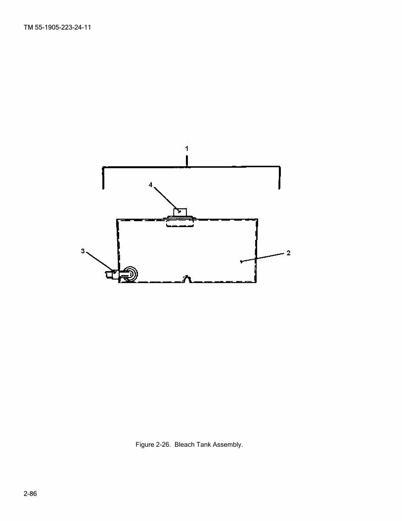
TM 55-1905-223-24-11
2-86
Figure 2-26. Bleach Tank Assembly.

TM 55-1905-223-24-11
2-87
2-24. Commode Warning Light Assembly. (Figure 2-27). This task covers: a. Repair, b. Replacement.
________ WARNING
Use extreme caution when checking energized circuits to avoid electrocution. Always ensure affected circuits have been secured, locked out and tagged out. Performing maintenance with circuits energized may result in death or injury to personnel or equipment damage.
CAUTION
The sanitary system has a commode warning light and audible alarm mounted in the 01 level passageway. A tank FULL condition exists when the red light is Illuminated. The toilet(s) must not be flushed until the light is out. See caution plate on the light case (3, Figure 2-27).
REMOVAL a. Remove panel screws (4) from each corner of the assembly (1). Remove front panel (2) to expose the
lamp socket (7) with wiring connections. b. Unscrew the locknut on the lamp socket (7) from inside the case of the assembly. Remove the socket
with bulb (8) and the red lens (5). c. Remove the bulb (8) from the socket (7). d. Remove the electrical wires from the terminals on the base of the lamp socket (7). e. Disconnect the cable connector (6). f. Remove the assembly from its mounting and withdraw the electrical wires through the bottom of the cable
connector. REPAIR Repair to the commode warning light assembly is by the replacement of the lens or lamp bulb. Refer to Removal and Replacement sections within this task.
INITIAL SETUP Tools Equipment Condition Tool kit, general mechanic's, TM 55-1905-223-10, marine sanitation system secured, 5180-00-699-5273 locked out and tagged (FM 55-502). Tool kit, electrician’s, 5180-00-391-1087 Materials/Parts Warning tag, Item 18, Section II, Appendix C

TM 55-1905-223-24-11
2-88
REPLACEMENT
a. Pull the electrical wires through the cable connector (6) on the bottom of the assembly. b. Mount the assembly and tighten the cable connector until snug. c. Insert a new bulb (8) in the socket (7). d. Position the red lens (5) in the assembly (1) and connect the socket and bulb with the socket locknut. e. Connect the electrical wires to the terminals on the base of the socket. f. Install the front panel (2) with the four screws (4). g. Restore electrical power, start the unit, and conduct operational check (Paragraph 2-6). h. Operate the MSD (Paragraph 2-6) and check covers, gaskets, piping and hoses for leaks, correct as
necessary.
Figure 2-27. Commode Warning Light Assembly.

TM 55-1905-223-24-11
2-89/(2-90 blank)
SECTION VI. PREPARATION FOR STORAGE OR SHIPMENT 2-25. AAdministrative Storage. Administrative storage of equipment issued to and used by Army activities will have preventive maintenance performed in accordance with the Preventive Maintenance Checks and Services (PMCS) charts before storing. When removing the equipment from administrative storage, the PMCS should be performed to assure operational readiness. Prepare components for shipment or limited storage in accordance with the following instructions. a. Operate MSD to discharge all effluent. b. Flush and drain MSD (Paragraph 2-6). c. Upon completion of flushing, place ships power switch to OFF position. d. Shut sewage inlet (PL-11 and PL-3) and seawater supply to MSD (SW-14). e. Shut bleach tank isolation valve. f. Place MSD power supply from ships electrical power to the off position. g. Shaft extensions and other exposed machine surfaces should be coated with an easily removable
rust preventive. h. Place a corrosion inhibitor in the pump casing such as Gulf-no-Rust Engine Oil, Grade 3, which
conforms to MIL-PRF-21260. i. Cover components to protect them from weather and direct sunlight. j. Either allow proper ventilation or tightly seal cover with a suitable amount of desiccant to ensure
dryness. k. Storage locations for pumps that are near a source of vibration must be avoided. l. If there exists a possibility of freezing or the MSD is scheduled to be in storage for a prolonged
period of time drain the MSD (Paragraph 2-6). m. Shafts should be rotated 10-15 times 2 or 3 times a month while in storage. n. If components are to be in extended storage, repeat preparation procedures every 6 months.


TM 55-1905-223-24-11
3-1
CHAPTER 3
INTERMEDIATE DIRECT SUPPORT MAINTENANCE INSTRUCTIONS
Page Section I Repair Parts, Special Tools; Test, Measurement and Diagnostic Equipment (TMDE); and Support Equipment ............................................................................................................................. 3-1 Section II Service Upon Receipt ........................................................................................................... 3-1 Section III Intermediate Direct Support Preventive Maintenance Checks and and Services (PMCS)............................................................................................................ 3-2 Section IV Intermediate Direct Support Troubleshooting ....................................................................... 3-3 Section V Intermediate Direct Support Maintenance Procedures......................................................... 3-5 Section VI Preparation for Storage or Shipment .................................................................................... 3-22
SECTION I. REPAIR PARTS, SPECIAL TOOLS; TEST, MEASUREMENT, AND DIAGNOSTIC EQUIPMENT (TMDE); AND SUPPORT EQUIPMENT
3-1. CCommon Tools and Equipment. For authorized common tools and equipment, refer to the Modified Table of Organization and Equipment (MTOE), CTA 50-970, Expendable/Durable Items (Except: Medical, Class V, Repair Parts, and Heraldic Items), CTA 50-909, Field and Garrison Furnishings and Equipment or CTA 8-100, Army Medical Department Expendable/Durable Items, as applicable to your unit. 3-2. SSpecial Tools, TMDE, and Support Equipment. Special tools; test, measurement, and diagnostic equipment; and support equipment requirements are listed and illustrated in the Repair Parts and Special Tools List (RPSTL), TM 55-1905-223-24P. These items are also listed in the Maintenance Allocation Chart (MAC), Appendix B of this manual. 3-3. Repair Parts. Repair parts are listed and illustrated in the Repair Parts and Special Tools List (RPSTL), TM 55-1905-223-24P.
SECTION II. SERVICE UPON RECEIPT 3-4. CChecking Unpacked Equipment. a. Inspect the equipment for damage incurred during shipment. If the equipment has been damaged, report
the damage in accordance with the instructions of DA PAM 750-8. b. Check the equipment against the packing slip to see if the shipment is complete. Report all discrepancies
in accordance with the instructions of DA PAM 750-8. c. Check to see whether the equipment has been modified. d. Remove and replace protective caps, plugs, inserts, wrappings, and tape when inspection/inventory is
completed. Inspect piping openings for damage. Wipe off dirt, grease, or protective films at time of installation.
e. Remove chocks from resilient mounted components.

TM 55-1905-223-24-11
3-2
SECTION III. INTERMEDIATE DIRECT SUPPORT PREVENTIVE MAINTENANCE CHECKS AND SERVICES (PMCS)
3-5. Explanation Of The PMCS Table. PMCS is designed to keep the equipment in good working condition. This is accomplished by performing certain tests, inspections, and services. Table 3-1 lists items to be serviced and the procedures needed to accomplish the PMCS. If needed, PMCS may be performed more frequently than the indicated interval. The “Procedures” column tells you how to perform the required checks and services. If your equipment does not perform as required, see Table 3-2, Troubleshooting. Report any malfunctions or failures on DA Form 2404/5988E, Equipment Inspection and Maintenance Worksheet. In the “TM” Number column on the DA Form 2404/5988E, record the appropriate Item Number from the PMCS table.
Table 3-1. Preventive Maintenance Checks and Services (PMCS)
(To be Performed Every 3 Years)
Item No.
Items To Be Inspected/Serviced
Procedures
Equipment Is Not Ready/ Available If:
1
Macerator
________ WARNING
Use extreme caution when checking energized circuits to avoid electrocution. Always ensure affected circuits have been secured, locked out and tagged out. Performing maintenance with circuits energized may result in death or injury to personnel or equipment damage.
CAUTION
Do not operate macerator or pumps dry. Lack of liquid may cause severe damage to the unit. Remove and clean with water (Paragraphs 2-18 and 3-8). Inspect internal parts for wear and other damage.
Rotor shredder cracked or damaged.

TM 55-1905-223-24-11
3-3
SECTION IV. INTERMEDIATE DIRECT SUPPORT TROUBLESHOOTING
3-6. Troubleshooting. Both a symptom index and a troubleshooting table are provided. The symptom index will help you locate the information you need for troubleshooting.
SYMPTOM INDEX
Troubleshooting Procedure (Table 3-2)
MACERATOR
Large amounts of oil or grease on motor surfaces. Macerator operation noisy or vibrates excessively. A pump status light constantly illuminated, Power On light is illuminated, system not operating in AUTO mode. Unit stops or fails to run. Marine Sanitation Device working, but processes slowly
Item 4
Item 3
Item 1
Item 2
Item 5
Table 3-2 lists the common fault conditions that may be found during operation or maintenance of the equipment. Look for causes and do corrective actions in the order listed. This manual cannot list every symptom that may show up, and it cannot list all the possible causes and corrective actions. If a symptom is not listed, or if it keeps up after you have performed the corrective actions, notify your supervisor.
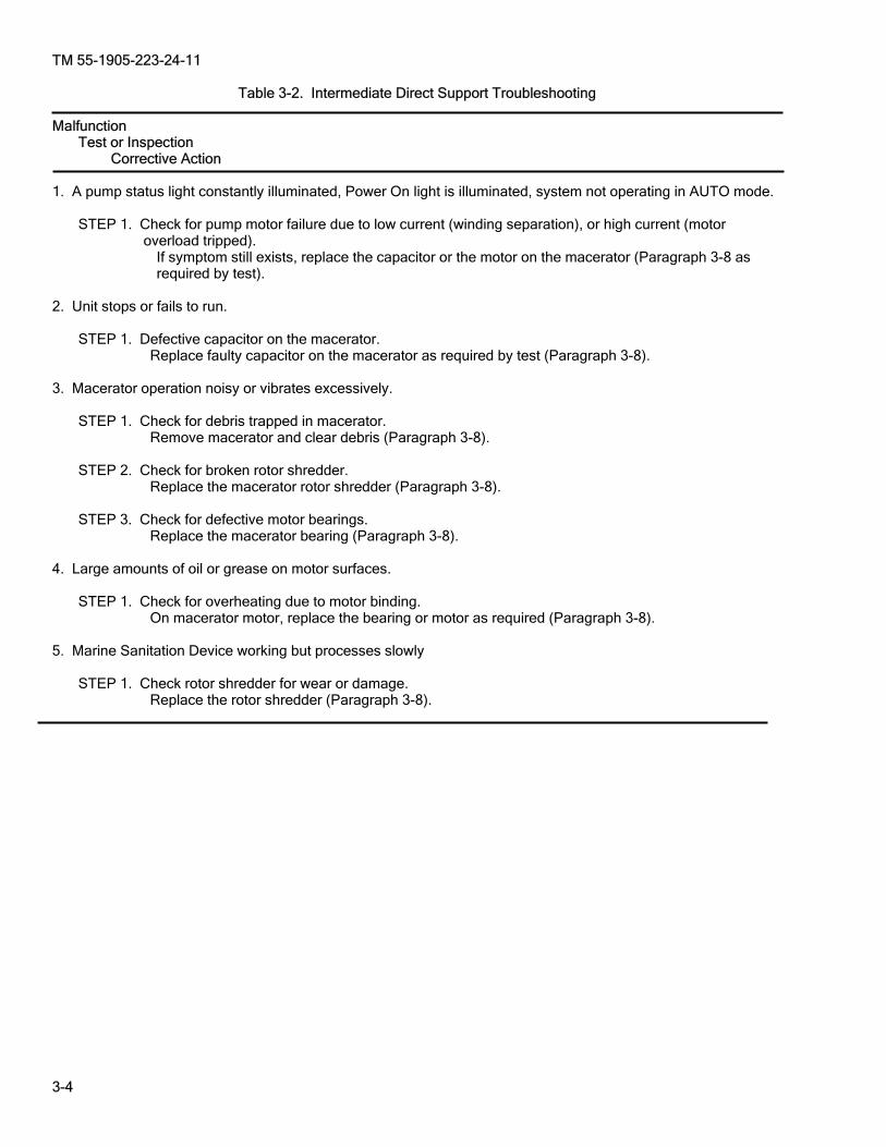
TM 55-1905-223-24-11
3-4
Table 3-2. Intermediate Direct Support Troubleshooting Malfunction Test or Inspection Corrective Action 1. A pump status light constantly illuminated, Power On light is illuminated, system not operating in AUTO mode.
STEP 1. Check for pump motor failure due to low current (winding separation), or high current (motor overload tripped).
If symptom still exists, replace the capacitor or the motor on the macerator (Paragraph 3-8 as required by test).
2. Unit stops or fails to run. STEP 1. Defective capacitor on the macerator. Replace faulty capacitor on the macerator as required by test (Paragraph 3-8). 3. Macerator operation noisy or vibrates excessively. STEP 1. Check for debris trapped in macerator. Remove macerator and clear debris (Paragraph 3-8). STEP 2. Check for broken rotor shredder. Replace the macerator rotor shredder (Paragraph 3-8). STEP 3. Check for defective motor bearings. Replace the macerator bearing (Paragraph 3-8). 4. Large amounts of oil or grease on motor surfaces. STEP 1. Check for overheating due to motor binding. On macerator motor, replace the bearing or motor as required (Paragraph 3-8). 5. Marine Sanitation Device working but processes slowly STEP 1. Check rotor shredder for wear or damage. Replace the rotor shredder (Paragraph 3-8).
TM 55-1905-223-24-11
3-5
SECTION V. INTERMEDIATE DDIRECT SUPPORT MAINTENANCE PROCEDURES 3-7. General. This section provides intermediate direct support maintenance for the marine sanitation device. To review the principles of operation for the marine sanitation device, refer to Chapter 1, Section III. Removal and replacement tasks are given in the following paragraphs.
________ WARNING
GAS HAZARD. A serious potential hazard associated with sewage systems is hydrogen sulfide (H2S). It is a colorless, flammable, toxic gas with a characteristic smell of rotten eggs at low concentrations. However the sense of smell is lost after 2-15 minutes of exposure making it impossible to smell dangerous concentrations. The permissible exposure limit (PEL) for H2S is 10 parts of H2S for every million parts of air (commonly expressed as 10 ppm H2S). The IDLH (Immediately. Dangerous to Life or Health) limit is 100 ppm H2S. In addition when H2S burns, it produces another very toxic gas, sulfur dioxide (SO2). For additional information, refer to Naval Ships’ Technical Manual (NSTM) Chapter 593, POLLUTION CONTROL, S9086–T8–STM-010.
________ WARNING
CHEMICAL HAZARD. Personal protective equipment (PPE) must be worn to avoid contact with skin and splashing in eyes. Avoid prolonged breathing of fumes.
________ WARNING
DISEASE HAZARD. Good personal hygiene habits by those operating and servicing the MSD are imperative. Washing of hands with hot, potable water and disinfectant soap should be accomplished after coming in contact with sewage or any contaminated equipment. Personnel shall not be allowed to eat, smoke, or drink, in the MSD pump room. Personnel with skin abrasions, punctures, or any other wounds shall not be allowed to service MSD equipment. In order to minimize the risks of health and sanitation hazards associated with the MSD, personnel shall follow sanitary and hygienic practices contained in section 4 of NSTM Chapter 593, S9086–T8–STM-010. When performing maintenance, which requires disassembly of sewage equipment or when contact with sewage is possible, personnel protective equipment (PPE) specified in section 4 of NSTM Chapter 593, S9086–T8–STM-010 shall be donned.
________ WARNING
TOXIC AND FLAMMABLE HAZARD. A potential sewage system hazard is fire or explosion. The sewage holding tank and system piping should be considered to contain some type of combustible. Combustible gases, such as hydrogen sulfide and methane, may be formed inside the holding tank or piping due to biological decomposition of organics. Under normal operating conditions, most other gases that are potentially flammable do not form in concentrations high enough to approach the explosive limit. Fuels may also be inadvertently collected in holding tanks from deck drains or through common bulkheads, and decks between fuel oil tanks and holding tanks, which have failed. In order to minimize the potential for a fire or explosion hazard, the following precautions should be taken: 1. Ensure the installed holding tank aeration system (if installed) is operated to reduce the amount of hydrogen sulfide. 2. Follow NSTM Chapter 593, (Pollution Control) when conducting hot work on any part of a sewage system.

TM 55-1905-223-24-11
3-6
3. Use only approved intrinsically safe, spark-proof or explosion-proof equipment when flammable or explosive vapors, gases, or materials are present. Control all other potential ignition sources and provide adequate fire protection measures for the specific exposure. 4. Never permit smoking, eating, or drinking inside the sewage system spaces. 5. Always exercise caution when cleaning up fuel or flammable liquid spills. These fluids shall be containerized and sealed for shore disposal by the base public works department. The disposal of flammable or toxic liquids to the sewage holding tank by way of the waste or sewage drains is strictly prohibited.

TM 55-1905-223-24-11
3-7
3-8. Macerator Pump Assembly. This task covers: a. Test, b. Repair, c. Replacement.
TEST ________ WARNING
Use extreme caution when checking energized circuits to avoid electrocution. Always ensure affected circuits have been secured, locked out and tagged out. Performing maintenance with circuits energized may result in death or injury to personnel or equipment damage.
a. Test Capacitor. Turn the electrical power OFF to the MSD system and check the capacitor (33, Figure 3-1) as follows:
________ WARNING
Capacitor maintains charge and presents a shock hazard. Discharge capacitor prior to handling. Avoid contact with motor, capacitor and metal portions of the screwdriver while discharging to avoid personal injury.
(1) With the electrical power OFF, remove the machine screws (31, Figure 3-1). Remove the capacitor cover (30) for access to the capacitor (33).
(2) Discharge the capacitor (33) before removing. Discharge capacitor, prior to handling by placing the
metal blade of an insulated screwdriver across the terminals and shorting out the capacitor. (3) Label and disconnect the electrical leads from the capacitor.
INITIAL SETUP Tools Equipment Condition Tool kit, general mechanic's, System drained and flushed (Paragraph 2-6). 5180-00-699-5273 TM 55-1905-223-10, marine sanitation system secured, Tool kit, electrician’s, locked out and tagged (FM 55-502). 5180-00-391-1087 Macerator removed (Paragraph 2-18). Multimeter, 6625-01-265-6000 Crowbar, 5210-00-224-1344 Mallet, Rubber, 5210-00-293-3399 Materials/Parts Crocus cloth, fine, Item 6, Section II, Appendix C Gloves, chemical, Item 8, Section II, Appendix C Goggles, Item 9, Section II, Appendix C Oil, Item 10, Section II, Appendix C Remover, Paint, Item 12, Section II, Appendix C Silicone, Sealant, Item 13, Section II, Appendix C Warning tags, Item 18, Section II, Appendix C Part Kit Bearing P/N 370088-049 Block, Wood

TM 55-1905-223-24-11
3-8
(4) Check the capacitor (33) as follows: (a) Discharge capacitor again (step 2). (b) Connect a multimeter to both terminals on the capacitor, place multimeter in the 10,000 ohms
setting and check resistance. (c) Observe scale reading of multimeter. If reading is constant infinity, discharge capacitor, and
reverse lead connection from multimeter. If still infinite, replace the capacitor. If scale on multimeter is spanned (travels upscale and then stops) when checking, the capacitor is serviceable.
(d) Discharge the capacitor again prior to handling. (5) Connect the electrical leads to their proper terminals on the capacitor. (6) Install the case (30) with the screws (31) to hold the capacitor in place. (7) Turn the electrical power ON, start the MSD system, and check the motor for proper operation
(Paragraph 2-6). (8) If the motor is still inoperative, continue with step b.
________ WARNING
Use extreme caution when checking energized circuits to avoid electrocution. Always ensure affected circuits have been secured, locked out and tagged out. Performing maintenance with circuits energized may result in death or injury to personnel or equipment damage.
b. Test Motor. Turn the electrical power OFF and check the motor for an open, shorted, or grounded
condition. (1) Label and disconnect the cable leads from the motor terminals. Clean the motor terminals. (2) Use a multimeter on the ohms setting and check for a short in the windings. Check the resistance
between the power supply terminals (red and black) on the motor. If no deflection (infinity) is obtained on the meter, the windings are open. If a full deflection (zero reading) is obtained, the motor windings are shorted.
(3) Use a multimeter on the ohms (10,000 ohms scale) setting and check for an external ground.
Check each terminal on the motor by placing one multimeter lead to a motor terminal and the other lead to a clean, unpainted spot on the metal housing of the motor. If any deflection or resistance other than infinity is shown on the meter, the motor has an external ground and must be replaced.
(4) Replace the ac motor assembly if an open, shorted or grounded condition exists (Paragraph 2-18). REPAIR
________ WARNING
DISEASE HAZARD. Personal protective equipment (PPE) must be worn since a small amount of effluent may still be contained within the macerator. Flush macerator thoroughly with clean water before opening.
Upper housing repair to the (pump portion) of the macerator is by replacement of worn or damaged components.

TM 55-1905-223-24-11
3-9
DISASSEMBLY. See Figure 3-1 and proceed as follows: a. Place unit on bench upside down. b. Remove terminal box (37, Figure 3-1) by removing screw (38). Remove grommet (39). c. Remove screws (28) and turn unit so discharge outlet is facing toward you.
Figure 3-1. Macerator Pump Assembly.

TM 55-1905-223-24-11
3-10
d. Grasp trim band (27, Figure 3-2) with both hands. Spread band wide enough to clear bottom cover (47). Angle upper edge of band towards you so opening in shell passes over terminal connection area. Remove Band.
e. Reach up under the cover (47) and remove screws (22, Figure 3-3) and washers (21). Lift the body and
cover assembly (5, Figure 3-1) off the upper body assembly. f. Remove motor bolts (46). Remove cover (47, Figure 3-4) and spacers (45).
Figure 3-2. Band Removal.
Figure 3-3. Body/Cover Removal.
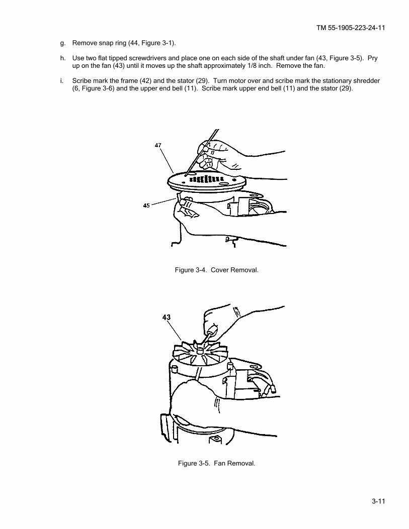
TM 55-1905-223-24-11
3-11
g. Remove snap ring (44, Figure 3-1). h. Use two flat tipped screwdrivers and place one on each side of the shaft under fan (43, Figure 3-5). Pry
up on the fan (43) until it moves up the shaft approximately 1/8 inch. Remove the fan. i. Scribe mark the frame (42) and the stator (29). Turn motor over and scribe mark the stationary shredder
(6, Figure 3-6) and the upper end bell (11). Scribe mark upper end bell (11) and the stator (29).
Figure 3-4. Cover Removal.
Figure 3-5. Fan Removal.
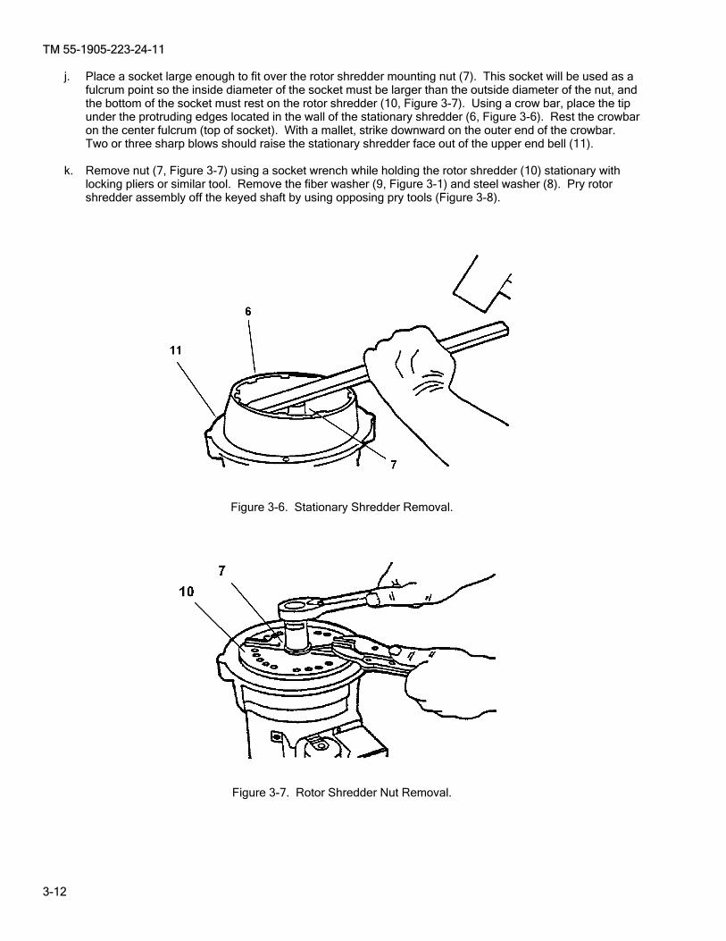
TM 55-1905-223-24-11
3-12
j. Place a socket large enough to fit over the rotor shredder mounting nut (7). This socket will be used as a fulcrum point so the inside diameter of the socket must be larger than the outside diameter of the nut, and the bottom of the socket must rest on the rotor shredder (10, Figure 3-7). Using a crow bar, place the tip under the protruding edges located in the wall of the stationary shredder (6, Figure 3-6). Rest the crowbar on the center fulcrum (top of socket). With a mallet, strike downward on the outer end of the crowbar. Two or three sharp blows should raise the stationary shredder face out of the upper end bell (11).
k. Remove nut (7, Figure 3-7) using a socket wrench while holding the rotor shredder (10) stationary with
locking pliers or similar tool. Remove the fiber washer (9, Figure 3-1) and steel washer (8). Pry rotor shredder assembly off the keyed shaft by using opposing pry tools (Figure 3-8).
Figure 3-6. Stationary Shredder Removal.
Figure 3-7. Rotor Shredder Nut Removal.

TM 55-1905-223-24-11
3-13
l. Remove two keys (20, Figure 3-1) and slide moisture shield (12) up and free of motor shaft (23). Scribe mark end bell (11) and stator (29). Lay unit on side and tap upper end bell (11, Figure 3-9) alternately on opposite side with a soft mallet until end bell is disengaged. Pull upper end bell (11) out and free of rotor and shaft assembly (23, Figure 3-1). Remove spring washer (41) from lower frame (42). Remove start switch (25) by remove screws (26).
m. Remove face seal assembly (14, Figure 3-1) by removing screws (13). Remove sleeve spacer (15) and
third shaft key (20). n. Remove O-ring (16) and slinger (17). o. Remove oil and water seal (19, Figure 3-10) and bearing (18, Figure 3-11).
Figure 3-8. Rotor Shredder Assembly Removal.
Figure 3-9. Upper End Bell Removal.
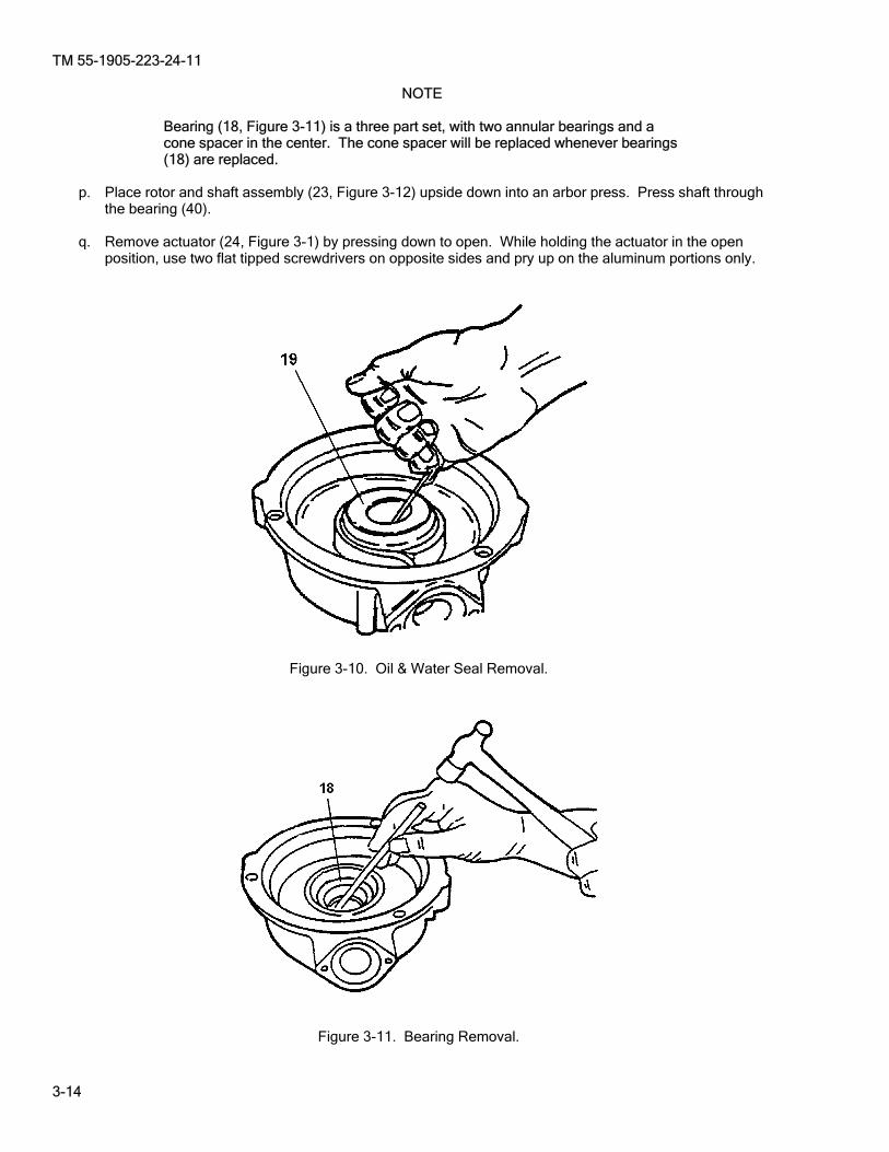
TM 55-1905-223-24-11
3-14
NOTE
Bearing (18, Figure 3-11) is a three part set, with two annular bearings and a cone spacer in the center. The cone spacer will be replaced whenever bearings (18) are replaced.
p. Place rotor and shaft assembly (23, Figure 3-12) upside down into an arbor press. Press shaft through
the bearing (40). q. Remove actuator (24, Figure 3-1) by pressing down to open. While holding the actuator in the open
position, use two flat tipped screwdrivers on opposite sides and pry up on the aluminum portions only.
Figure 3-10. Oil & Water Seal Removal.
Figure 3-11. Bearing Removal.
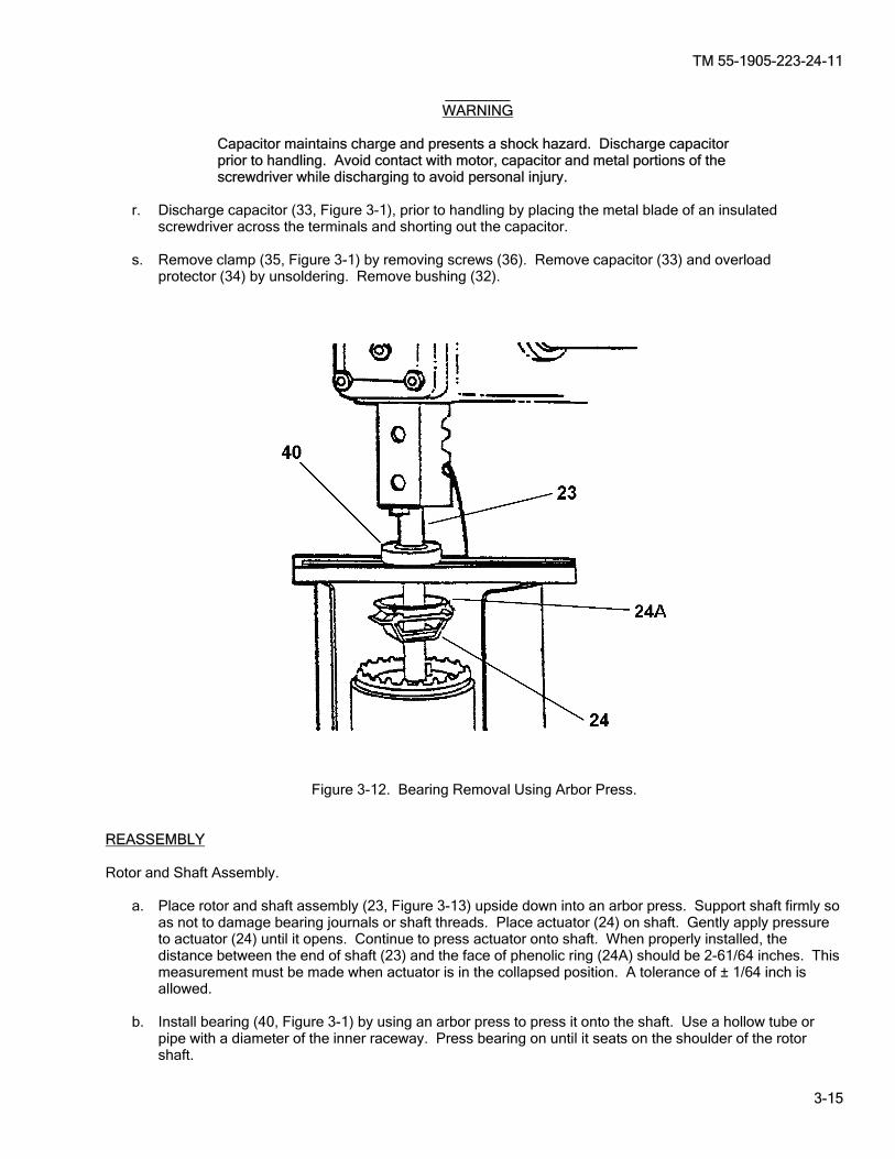
TM 55-1905-223-24-11
3-15
________ WARNING
Capacitor maintains charge and presents a shock hazard. Discharge capacitor prior to handling. Avoid contact with motor, capacitor and metal portions of the screwdriver while discharging to avoid personal injury.
r. Discharge capacitor (33, Figure 3-1), prior to handling by placing the metal blade of an insulated
screwdriver across the terminals and shorting out the capacitor. s. Remove clamp (35, Figure 3-1) by removing screws (36). Remove capacitor (33) and overload protector (34) by unsoldering. Remove bushing (32).
Figure 3-12. Bearing Removal Using Arbor Press.
REASSEMBLY Rotor and Shaft Assembly. a. Place rotor and shaft assembly (23, Figure 3-13) upside down into an arbor press. Support shaft firmly so
as not to damage bearing journals or shaft threads. Place actuator (24) on shaft. Gently apply pressure to actuator (24) until it opens. Continue to press actuator onto shaft. When properly installed, the distance between the end of shaft (23) and the face of phenolic ring (24A) should be 2-61/64 inches. This measurement must be made when actuator is in the collapsed position. A tolerance of ± 1/64 inch is allowed.
b. Install bearing (40, Figure 3-1) by using an arbor press to press it onto the shaft. Use a hollow tube or
pipe with a diameter of the inner raceway. Press bearing on until it seats on the shoulder of the rotor shaft.
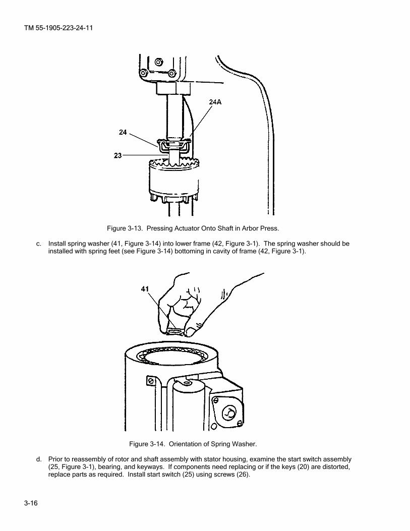
TM 55-1905-223-24-11
3-16
Figure 3-13. Pressing Actuator Onto Shaft in Arbor Press.
c. Install spring washer (41, Figure 3-14) into lower frame (42, Figure 3-1). The spring washer should be
installed with spring feet (see Figure 3-14) bottoming in cavity of frame (42, Figure 3-1).
Figure 3-14. Orientation of Spring Washer.
d. Prior to reassembly of rotor and shaft assembly with stator housing, examine the start switch assembly
(25, Figure 3-1), bearing, and keyways. If components need replacing or if the keys (20) are distorted, replace parts as required. Install start switch (25) using screws (26).
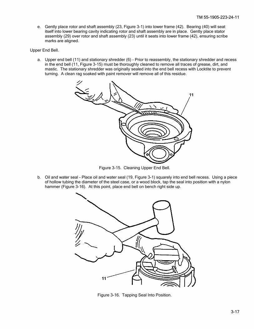
TM 55-1905-223-24-11
3-17
e. Gently place rotor and shaft assembly (23, Figure 3-1) into lower frame (42). Bearing (40) will seat itself into lower bearing cavity indicating rotor and shaft assembly are in place. Gently place stator
assembly (29) over rotor and shaft assembly (23) until it seats into lower frame (42), ensuring scribe marks are aligned.
Upper End Bell. a. Upper end bell (11) and stationary shredder (6) - Prior to reassembly, the stationary shredder and recess
in the end bell (11, Figure 3-15) must be thoroughly cleaned to remove all traces of grease, dirt, and mastic. The stationary shredder was originally sealed into the end bell recess with Locktite to prevent turning. A clean rag soaked with paint remover will remove all of this residue.
Figure 3-15. Cleaning Upper End Bell.
b. Oil and water seal - Place oil and water seal (19, Figure 3-1) squarely into end bell recess. Using a piece
of hollow tubing the diameter of the steel case, or a wood block, tap the seal into position with a nylon hammer (Figure 3-16). At this point, place end bell on bench right side up.
Figure 3-16. Tapping Seal Into Position.

TM 55-1905-223-24-11
3-18
c. Cone spacer - The cone spacer (component of 18, Figure 3-1) is machined to properly space the two tapered roller bearings when they are installed in the end bell. It is not interchangeable with any other cone spacer. If new bearings are installed, the new cone spacer furnished with the bearing set must be used.
d. Upper tapered roller bearing - Install new upper tapered roller bearing (18, Figure 3-1) in end bell recess. e. Install slinger (17) on top of upper tapered roller bearing (18). f. Install upper end bell (11) onto stator (29), aligning scribe marks from disassembly.
Figure 3-16. Tapping Seal Into Position.
NOTE
The O-ring (16) and sleeve spacer (15) are designed to fit snugly on the shaft, but not tight. If it is too loose or too tight, replace O-ring (16). Make this check prior to reassembly of the moisture shield into the end bell (11). There is no way of determining its proper fit once the end bell is assembled and fitted to the motor assembly
g. Install O-ring (16) over shaft and insert third shaft key (20). Install sleeve spacer (15) over shaft, key and
O-ring with recess facing slinger. h. Face seal - Prior to reassembly, be sure that the face seal assembly (14, Figure 3-17) recess in the end
bell is clean and free of dirt, grease, etc. Lubricate the outside edge of the seal with oil for ease of installation. Place seal in recess and push down evenly until metal surface of the seal seats solidly into the recess (Figure 3-17) secure with screws (14). Install moisture shield (12) over shaft and third key.(20).
NOTE
Prior to reassembly, the rotor shredder (10, Figure 3-1) should be carefully inspected to determine if it is reusable. The seal surface of the shredder, where it comes in contact with the face seal assembly (14, Figure 3-17), should be examined closely. If the surface is not smooth and free of defects, or if the horizontal bars on the top surface of the shredder show signs of excessive wear or are broken, the rotor shredder should be replaced.
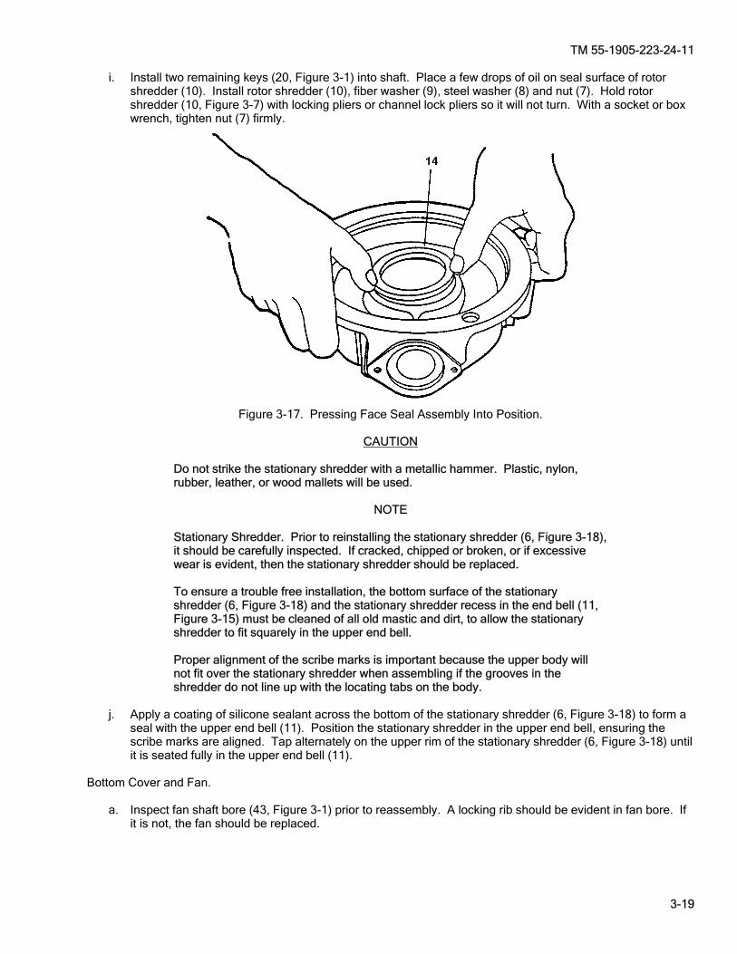
TM 55-1905-223-24-11
3-19
i. Install two remaining keys (20, Figure 3-1) into shaft. Place a few drops of oil on seal surface of rotor shredder (10). Install rotor shredder (10), fiber washer (9), steel washer (8) and nut (7). Hold rotor shredder (10, Figure 3-7) with locking pliers or channel lock pliers so it will not turn. With a socket or box wrench, tighten nut (7) firmly.
Figure 3-17. Pressing Face Seal Assembly Into Position.
CAUTION
Do not strike the stationary shredder with a metallic hammer. Plastic, nylon, rubber, leather, or wood mallets will be used.
NOTE
Stationary Shredder. Prior to reinstalling the stationary shredder (6, Figure 3-18), it should be carefully inspected. If cracked, chipped or broken, or if excessive wear is evident, then the stationary shredder should be replaced. To ensure a trouble free installation, the bottom surface of the stationary shredder (6, Figure 3-18) and the stationary shredder recess in the end bell (11, Figure 3-15) must be cleaned of all old mastic and dirt, to allow the stationary shredder to fit squarely in the upper end bell. Proper alignment of the scribe marks is important because the upper body will not fit over the stationary shredder when assembling if the grooves in the shredder do not line up with the locating tabs on the body.
j. Apply a coating of silicone sealant across the bottom of the stationary shredder (6, Figure 3-18) to form a seal with the upper end bell (11). Position the stationary shredder in the upper end bell, ensuring the scribe marks are aligned. Tap alternately on the upper rim of the stationary shredder (6, Figure 3-18) until it is seated fully in the upper end bell (11).
Bottom Cover and Fan. a. Inspect fan shaft bore (43, Figure 3-1) prior to reassembly. A locking rib should be evident in fan bore. If
it is not, the fan should be replaced.

TM 55-1905-223-24-11
3-20
Figure 3-18. Reseating Stationary Shredder. b. Place fan (43, Figure 3-1) on the shaft while making sure that flat surfaces of fan shaft bore line up with
flat surfaces on the shaft. c. With a rawhide or plastic mallet, tap on the fan hub until the end of the shaft and fan hub are even. Then
place one thumb on each side of the fan hub and press down firmly. The locking rib in the fan shaft bore will seat itself in the locking groove on the shaft.
d. Reinstall snap ring (44, Figure 3-1). e. Place bottom cover (47, Figure 3-1) on unit. Bottom cover will only fit one way. Be sure to align motor bolt
holes in bottom cover with motor bolt holes in lower end bell. f. Ensure spacer tubes (45, Figure 3-19) are placed on motor bolts (46, Figure 3-1) between bottom cover (47) and motor bolt hole in lower end bell (11). After this is done, bolts can be threaded into the
upper end bell.
Figure 3-19. Spacer Tube Installation.

TM 55-1905-223-24-11
3-21
Body and Cover Assembly.
CAUTION
Ensure the gaskets (4 and 2, Figure 3-1) are positioned properly when replacing the housings (5, 3).
a. Inspect body shredder seal (4, Figure 3-1). If damaged or deteriorated, replace it. b. Place unit on a bench in an upright position. c. Position body and cover assembly (1, Figure 3-1) on upper end bell (11), ensuring locating tabs are lined
up with the locating grooves in the stationary shredder (6). d. Place capscrew (22, Figure 3-1) with washer (21) in a socket wrench. Insert wrench up under end bell (11) and guide capscrew to capscrew hole. Thread capscrew about one half way in. Follow same
procedure with remaining capscrews until all are partially threaded. At this point you can complete the threading and tightening process.
Terminal Box and Trim Band. a. Place unit on bench upside down with discharge outlet facing toward you.
CAUTION
Use care so as not to damage lead wires in terminal box area. b. Grasp trim shell with both hands while holding trim band (27) in a horizontal position. Insert leading lower
edge of trim band in space between terminal connection and upper shroud. Raise band to a vertical position, at the same time spreading it so it will clear the bottom cover.
c. Reinstall two trim band retaining screws (28). d. Replace capacitor (33) and overload protector (34) by soldering. Install bushing (32). Replace clamp (35)
and secure with screws (36). e. Reassemble terminal box cover (37) to unit and secure with retaining screw (38). REPLACEMENT Install the macerator on the MSD system (Paragraph 2-18).
TM 55-1905-223-24-11
3-22
SECTION VI. PREPARATION FOR STORAGE OR SHIPMENT 3-9. AAdministrative Storage. Administrative storage of equipment issued to and used by Army activities will have preventive maintenance performed in accordance with the Preventive Maintenance Checks and Services (PMCS) charts before storing. When removing the equipment from administrative storage, the PMCS should be performed to assure operational readiness. Prepare marine sanitation device or components for shipment or limited storage in accordance with the following instructions. a. Operate MSD to discharge all effluent. b. Flush and drain MSD (Paragraph 2-6). c. Upon completion of flushing, place ships power switch to OFF position. d. Shut sewage inlet (PL-11 and PL-3) and seawater supply to MSD (SW-14). e. Shut bleach tank isolation valve. f. Place MSD power supply from ships electrical power to the off position. g. Shaft extensions and other exposed machine surfaces should be coated with an easily removable
rust preventive. h. Place a corrosion inhibitor in the pump casing such as Gulf-no-Rust Engine Oil, Grade 3, which
conforms to MIL-PRF-21260. i. Cover components to protect them from weather and direct sunlight. j. Either allow proper ventilation or tightly seal cover with a suitable amount of desiccant to ensure
dryness. k. Storage locations for pumps that are near a source of vibration must be avoided. l. If there exists a possibility of freezing or the MSD is scheduled to be in storage for a prolonged
period of time drain the MSD (Paragraph 2-6). m. Shafts should be rotated 10-15 times 2 or 3 times a month while in storage. n. If components are to be in extended storage, repeat preparation procedures every 6 months.
TM 55-1905-223-24-11
4-1/(4-2 blank)
CHAPTER 4
INTERMEDIATE GENERAL SUPPORT MAINTENANCE INSTRUCTIONS
Maintenance procedures for the Marine Sanitation System are performed at the Unit or Intermediate Direct Support maintenance levels. There are no maintenance requirements at the Intermediate General Support maintenance level.


TM 55-1905-223-24-11
A-1
APPENDIX A
REFERENCES A-1. SScope. This paragraph lists the manuals, bulletins, specifications, and miscellaneous publications referenced in this manual or required for maintenance activities. A-2. Field Manuals. FM 4-25.11 First Aid FM 31-70 Basic Cold Weather Manual FM 55-501 Marine Crewman's Handbook
FM 55-502 Army Watercraft Safety A-3. Technical Manuals. S9086-KC-STM-010 Naval Ships Technical Manual Chapter 300, Electric Plant General S9086-KE-STM-010 Naval Ships Technical Manual Chapter 302, Electric Motors And Controllers S9086-KE-STM-010 Naval Ships Technical Manual Chapter 310, Electric Motors And Controllers S9086-KY-STM-010 Naval Ships Technical Manual Chapter 320, Electric Power Distribution Systems S9086-CH-STM-030 Naval Ships Technical Manual Chapter 074, Volume 3 Gas Free Engineering S9086-T8-STM-010 Naval Ships Technical Manual Chapter 593, Pollution Control TM 43-0139 Painting Instructions for Army Materiel TM 55-1905-223-10 Operator's Manual for Landing Craft, Utility (LCU) TM 55-1905-223-24-18-1/2 LCU 2000 Class Basic Craft Maintenance Manual TM 55-1905-223-24P-1/2/3/4 Repair Parts and Special Tools List for the LCU 2000 Class Watercraft TM 750-244-3 Destruction of Army Materiel to Prevent Enemy Use A-4. TTechnical Bulletins.
TB 43-0144 Painting of Watercraft TB 55-1900-207-24 Treatment of Cooling Water in Marine Diesel Engines TB 740-97-4 Preservation of Vessels for Storage A-5. Military Specifications. MIL-PRF-16173 Corrosion Preventive Compound, Solvent Cutback, Cold-Application MIL-PRF-21260 Lubricating Oil, Internal Combustion Engine, Preservative Break-In MIL-PRF-32033 Lubricating Oil, General Purpose, Preservative (Water- Displacing, Low Temperature) A-6. Miscellaneous Publications. DA PAM 750-8 The Army Maintenance Management System (TAMMS) Users Manual LO 55-1905-223-12 Lubrication Order for the LCU 2000 Class Watercraft AR 750-10 Army Modification Program

TM 55-1905-223-24-11
A-2
A-7. FForms.
CTA 8-100 Army Medical Department Expendable/Durable Items CTA 90-970 Army Expendable/Durable Items DA Form 2028 Recommended Changes to Equipment Technical
Publications Blank Forms DA Form 2404/5988E Equipment Inspection and Maintenance Worksheet DA Form 2408-16 Logsheet DA Form 2410 Logsheet SF Form 368 Product Quality Deficiency Report

TM 55-1905-223-24-11
B-1
APPENDIX B. MAINTENANCE ALLOCATION CHART (MAC)
SECTION I. INTRODUCTION B-1. THE ARMY MAINTENANCE SYSTEM MAC. a. This introduction (Section I) provides a general explanation of all maintenance and repair functions
authorized at various maintenance levels under the standard Army Maintenance System concept. b. The Maintenance Allocation Chart (MAC) in Section II designates overall authority and responsibility for
the performance of maintenance functions on the identified end item or component. The application of the maintenance functions to the end item or component will be consistent with the capacities and capabilities of the designated maintenance levels, which are shown in the MAC in column (4) as:
Unit - includes two subcolumns: C (operator/crew) and O (unit) maintenance. Intermediate Direct Support - includes an F subcolumn. Intermediate General Support - includes an H subcolumn. Depot - includes a D subcolumn. c. Section lll lists the tools and test equipment (both special tools and common tools sets) required for each
maintenance function as referenced from Section II. d. Section IV contains supplemental instructions and explanatory notes for a particular maintenance function
as referenced from Section II. B-2. MAINTENANCE FUNCTIONS. Maintenance functions will be limited to and defined as follows: a. Inspect. To determine the serviceability of an item comparing its physical, mechanical, and/or electrical
characteristics with established standards through examination (i.e., by sight, sound, or feel). b. Test. To verify serviceability by measuring the mechanical, pneumatic, hydraulic, or electrical
characteristics of an item and comparing those characteristics with prescribed standards. c. Service. Operations required periodically to keep an item in operating condition, i.e., to clean (includes
decontamination, when required), to replace filters, to preserve, to drain, to paint, or to replenish fuel, lubricants, chemical fluids, or gases.
d. Adjust. To maintain or regulate, within prescribed limits, by bringing into proper or exact position, or by setting the operating characteristics to specified parameters.
e. Align. To adjust specified variable elements of an item to bring about optimum or desired performance. f. Calibrate. To determine and cause corrections to be made or to be adjusted on instruments or test,
measuring, and diagnostic equipment used in precision measurement. Consists of comparisons of two instruments, one of which is a certified standard of known accuracy, to detect and adjust any discrepancy in the accuracy of the instrument being compared.
g. Remove/install. To remove and install the same item when required to perform service or other maintenance functions. Install may be the act of emplacing, seating, or fixing into position a spare, repair part, or module (component or assembly) in a manner to allow the proper functioning of an equipment or system.
h. Replace. To remove an unserviceable item and install a serviceable counterpart in its place. Replace is authorized by the MAC and is shown as the 3rd position code of the SMR code.
i. Repair. The application of maintenance services1 including fault location/troubleshooting2, removal/installation, and disassembly/assembly3 procedures, and maintenance actions4 to identify troubles and restore serviceability to an item by correcting specific damage, fault, malfunction, or failure in a part, subassembly, module (component or assembly), and item, or system.
j. Overhaul. That maintenance effort (service/action), prescribed to restore an item to a completely serviceable/operational condition as required by maintenance standards in appropriate technical publications (i.e., DMWR). Overhaul is normally the highest degree of maintenance performed by the Army. Overhaul does not normally return an item to like new condition.
1Service - Inspect, test, service, adjust, align, calibrate, and/or replace. 2Fault location/troubleshooting - The process of investigating and detecting the cause of equipment malfunctioning; the act of isolating a fault within a system or unit under test (UUT). 3Disassembly/assembly - The step-by-step breakdown (taking apart) of a spare/functional group coded item to the level of its least component that is assigned an SMR code for the level of maintenance under consideration (i.e., identification as maintenance significant). 4Actions - Welding, grinding, riveting, straightening, facing, machining, and/or resurfacing.
TM 55-1905-223-24-11
B-2
k. Rebuild. Consists of those service/actions necessary for the restoration of unserviceable equipment to a like new condition in accordance with original manufacturing standards. Rebuild is the highest degree of material maintenance applied to Army equipment. The rebuild operation includes the act of returning to zero those age measurements (hours, miles, etc.) considered in classifying Army equipment and components.
B-3. EXPLANATION OF COLUMNS IN THE MAC, SECTION II a. Column 1 - Group Number. Column 1 lists functional group code numbers, the purpose of which is to
identify maintenance significant components, assemblies, subassemblies, and modules with the next higher assembly.
b. Column 2 - Component/Assembly. Column 2 contains the names of components, assemblies, subassemblies, and modules for which maintenance is authorized.
c. Column 3 - Maintenance Function. Column 3 lists the functions to be performed on the item listed in column 2. (For detailed explanation of these functions, refer to Paragraph B-2.)
d. Column 4 - Maintenance Category. Column 4 specifies, by the listing of a work time figure in the appropriate subcolumn(s), the category of maintenance authorized to perform the function listed in Column 3. This figure represents the active time required to perform that maintenance function at the indicated category of maintenance. If the number or complexity of the tasks within the listed maintenance function varies at different maintenance categories, appropriate work time figures will be shown for each category. The work time figure represents the average time required to restore an item (assembly, subassembly, component, module, end item, or system) to a serviceable condition under typical field operating conditions. This time includes preparation time (including any necessary disassembly/assembly time), troubleshooting/fault location time, and quality assurance/quality control time in addition to the time required to perform the specific tasks identified for the maintenance functions authorized in the maintenance allocation chart. The symbol designations for the various maintenance categories are as follows:
C Operator or Crew O Unit Maintenance F Intermediate Direct Support Maintenance (DS) H Intermediate General Support Maintenance (GS) D Depot Maintenance e. Column 5 - Tools and Equipment. Column 5 specifies, by number code, those common tool sets (not
individual tools); special tools; Test, Measurement, and Diagnostic Equipment (TMDE); and support equipment required to perform the designated function, which shall be keyed to the tools listed in Section III.
f. Column 6 - Remarks. This column shall, when applicable, contain a letter code, in alphabetic order, which shall be keyed to the remarks contained in Section IV.
B-4. EXPLANATION OF COLUMNS IN TOOL AND TEST EQUIPMENT REQUIREMENTS, SECTION Ill. a. Column I - Reference Code. The tool and test equipment reference code correlates with a number code
used in the MAC, Section II, Column 5. b. Column 2 - Maintenance Category. The lowest category of maintenance authorized to use the tool or test
equipment. c. Column 3 - Nomenclature. Name or identification of the tool or test equipment. d. Column 4 - National Stock Number. The National stock number (NSN) of the tool or test equipment. e. Column 5 - Tool Number. The manufacturer's part number. B-5. EXPLANATION OF COLUMNS IN REMARKS, SECTION IV. a. Column 1- Reference Code. The letter code recorded in Column 6, Section II. b. Column 2 - Remarks. This column lists information pertinent to the maintenance function being performed
as indicated in the MAC, Section II.
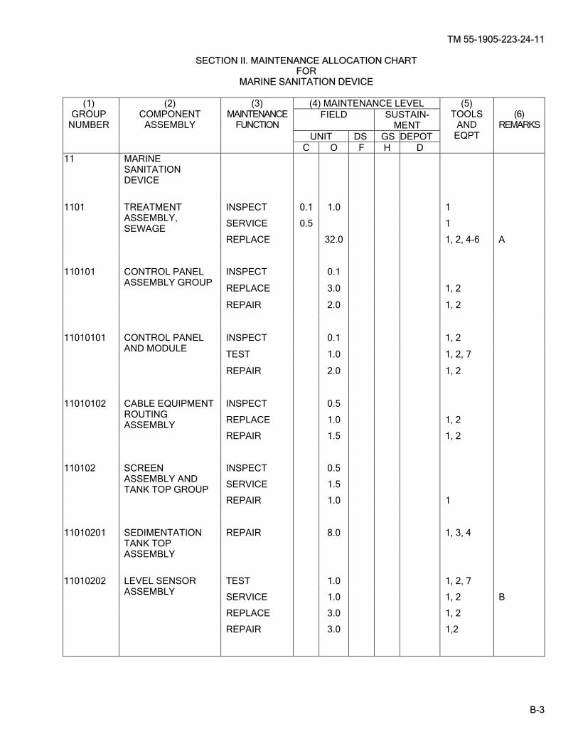
TM 55-1905-223-24-11
B-3
SECTION II. MAINTENANCE ALLOCATION CHART FOR
MARINE SANITATION DEVICE (4) MAINTENANCE LEVEL
FIELD SUSTAIN-MENT
UNIT DS GS DEPOT
(1) GROUP
NUMBER
(2) COMPONENT
ASSEMBLY
(3) MAINTENANCE
FUNCTION
C O F H D
(5) TOOLS
AND EQPT
(6)
REMARKS
11 MARINE SANITATION DEVICE
INSPECT 0.1 1.0 1
SERVICE 0.5 1
REPLACE 32.0 1, 2, 4-6 A
1101 TREATMENT ASSEMBLY, SEWAGE
INSPECT 0.1
REPLACE 3.0 1, 2
REPAIR 2.0 1, 2
110101 CONTROL PANEL ASSEMBLY GROUP
INSPECT 0.1 1, 2
TEST 1.0 1, 2, 7
REPAIR 2.0 1, 2
11010101 CONTROL PANEL AND MODULE
INSPECT 0.5
REPLACE 1.0 1, 2
REPAIR 1.5 1, 2
11010102 CABLE EQUIPMENT ROUTING ASSEMBLY
INSPECT 0.5
SERVICE 1.5
110102 SCREEN ASSEMBLY AND TANK TOP GROUP
REPAIR 1.0 1
11010201 SEDIMENTATION TANK TOP ASSEMBLY
REPAIR 8.0 1, 3, 4
TEST 1.0 1, 2, 7
SERVICE 1.0 1, 2 B
REPLACE 3.0 1, 2
11010202 LEVEL SENSOR ASSEMBLY
REPAIR 3.0 1,2

TM 55-1905-223-24-11
B-4
MAINTENANCE ALLOCATION CHART FOR
MARINE SANITATION DEVICE (cont)
(4) MAINTENANCE LEVEL FIELD SUSTAIN-
MENT UNIT DS GS DEPOT
(1) GROUP NUMBER
(2) COMPONENT
ASSEMBLY
(3) MAINTENANCE
FUNCTION
C O F H D
(5) TOOLS
AND EQPT
(6)
REMARKS
110103 MACERATOR PUMP ASSEMBLY GROUP
INSPECT 0.3 1, 2
TEST 1.0 1.0 1, 2, 7
SERVICE 4.0 1
REPLACE 2.0 1, 2
11010301 MACERATOR PUMP ASSEMBLY
REPAIR 1.0 6.0 1, 2, 8
110104 FLOW PUMP ASSEMBLY GROUP
INSPECT 0.3
TEST 0.5 1, 2, 7
ADJUST 1.0 1
REPLACE 1.5 1
11010401 FLOW PUMP ASSEMBLY
REPAIR 3.0 1, 9
INSPECT 0.3 1 110105 BACKWASH PIPING ASSEMBLY GROUP
REPAIR 3.0 1, 2
INSPECT 0.1
REPLACE 1.5 1 C
11010501 IMPACT SPRINKLER/BACKWASH NOZZLES
INSPECT 0.1 1
REPAIR 15.0 1, 2
110106 FLOW PIPING ASSEMBLY GROUP
INSPECT 0.3 1
SERVICE 0.2 1
REPLACE 1.0 1 C
1102 BLEACH TANK ASSEMBLY
REPLACE 2.0 1, 2 1103 COMMODE WARNING LIGHT ASSEMBLY
REPAIR 0.5 1

TM 55-1905-223-24-11
B-5/(B-6 blank)
SECTION Ill. TOOLS AND TEST EQUIPMENT REQUIREMENTS FOR
MARINE SANITATION DEVICE
TOOL OR TEST
EQUIPMENT REF
CODE
MAINTENANCE CATEGORY
NOMENCLATURE NATIONAL/NATO STOCK NUMBER
TOOL NUMBER
1
2
3
4
5
6
7
8
9
O, F
O, F
O
O
O
O
O, F
O
O
Tool Kit General Mechanic’s Tool Kit, Electricians Torque Wrench (30-200 in-lbs) Torque Wrench (30-200 ft-lbs) Lifting Sling Lifting Fixture Multimeter Wrench, Chain Puller, Mechanical
5180-00-699-5273 5180-00-391-1087 5120-01-092-3278 5120-01-125-5190 3940-01-183-9412 3940-01-397-0670 6625-01-265-6000 5120-01-018-3203 5120-00-499-1489
(50980) SC-5180-90-CL-N05 (62144) (80064) 9000S6202-7315ALT2 (15434) 3375958 (15434) 3822512 (80058) AN/PSM-45A (80020) 423170-1 (CJ83C) 55719
SECTION IV. REMARKS FOR
MARINE SANITATION DEVICE
REFERENCE CODE
REMARKS
A
DEPOT LEVEL REPAIR / MAINTENANCE WILL BE PERFORMED ON A CASE BY CASE BASIS SUBJECT TO APPROVAL AND FUNDING BY THE NATIONAL MAINTENANCE POINT (NMP).
B TWO DIFFERENT TYPES OF LEVEL SENSOR ASSEMBLIES EXIST ON THE MSD. PROBES WITH A SINGLE CABLE DESIGN AND FLOATS WITH A THREE CABLE DESIGN. THE SINGLE CABLE LEVEL SENSOR IS OBSOLETE. SERVICE IS ONLY APPLICABLE TO THE PROBES WITH A SINGLE CABLE DESIGN. IF SERVICING THE PROBES DOES NOT CORRECT THE PROBLEM, REPLACEMENT OF THE LEVEL SENSOR ASSEMBLY IS REQUIRED UTILIZING THE NEW RETRO FIT KIT.
C REPAIR IS BY REPLACEMENT.

TM 55-1905-223-24-11
C-1
APPENDIX C
EXPENDABLE/DURABLE SUPPLIES AND MATERIALS LIST
SECTION I. INTRODUCTION C-1. SScope. This appendix lists expendable supplies and materials you will need to operate and maintain the equipment. These items are authorized to you by CTA 50-970, Expendable/Durable Items (Except Medical, Class V, Repair Parts, and Heraldic Items), or CTA 8-100 Army Medical Department Expendable Items. C-2. EExplanation of Columns. The following provides an explanation of columns found in the tabular listings. a. Column (1) - Item Number. This number is assigned to the entry in the listing and is referenced in the
narrative instructions to identify the material (for example, "Use cleaning compound, item 5, App. C"). b. Column (2) - Level. This column identifies the lowest level of maintenance that requires the listed item. C - Operator/Crew O - Organizational Maintenance F - Intermediate Direct Support Maintenance H - Intermediate General Support Maintenance c. Column (3) National Stock Number. This is the National stock number assigned to the item; use it to
request or requisition the item. d. Column (4) - Description. Indicates the Federal item name and, if required, a description to identify the
item. The last line for each item indicates the Federal Supply Code for Manufacturers (FSCM) in parentheses followed by the part number.
e. Column (5) - Unit of Measure (U/M). Indicates the measure used in performing the actual maintenance
function. This measure is expressed by a two-character alphabetical abbreviation (for example, ea, in, pr). If the unit of measure differs from the unit of issue, requisition the lowest unit of issue that will satisfy your requirements.
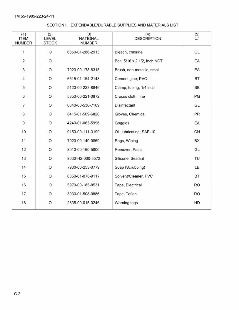
TM 55-1905-223-24-11
C-2
SECTION II. EXPENDABLE/DURABLE SUPPLIES AND MATERIALS LIST
(1) ITEM
NUMBER
(2) LEVEL STOCK
(3) NATIONAL NUMBER
(4) DESCRIPTION
(5) U/I
1 O 6850-01-286-2913 Bleach, chlorine GL
2 O Bolt, 5/16 x 2 1/2, Inch NCT EA
3 O 7920-00-178-8315 Brush, non-metallic, small EA
4 O 6515-01-154-2148 Cement glue, PVC BT
5 O 5120-00-223-8846 Clamp, tubing, 1/4 inch SE
6 O 5350-00-221-0872 Crocus cloth, fine PG
7 O 6840-00-530-7109 Disinfectant GL
8 O 8415-01-509-6826 Gloves, Chemical PR
9 O 4240-01-063-5996 Goggles EA
10 O 9150-00-111-3199 Oil, lubricating, SAE-10 CN
11 O 7920-00-140-0869 Rags, Wiping BX
12 O 8010-00-160-5800 Remover, Paint GL
13 O 8030-H2-000-5572 Silicone, Sealant TU
14 O 7930-00-253-0779 Soap (Scrubbing) LB
15 O 6850-01-078-9117 Solvent/Cleaner, PVC BT
16 O 5970-00-185-8531 Tape, Electrical RO
17 O 3930-01-508-0886 Tape, Teflon RO
18 O 2835-00-015-0246 Warning tags HD

TM 55-1905-223-24-11
D-1
APPENDIX D
TORQUE VALUES
D-1. SScope. SAE capscrews are graded according to the strength of the capscrew. They are marked on the head so the correct strength and torque value are known. The tables in this appendix will list the capscrew markings with correct torque values as well as values for pipe plugs and metric bolts.
CAUTION When replacing capscrews, always use a capscrew of the same measurement and strength as the capscrew being replaced. Using incorrect capscrews can result in equipment damage. Bolts threaded into aluminum require much less torque.
NOTE Always use torque values listed in the tables when specific torque values are unknown. The torque values listed in the tables are based on the use of lubricated threads.
Table D-1. Capscrew Markings and Torque Values
Capacity Body
size SAE Grade # 5
Cast Iron or Steel SAE Grade # 6 or # 7
Cast Iron or Steel SAE Grade #8
Cast Iron or Steel Inches-Thread TORQUE TORQUE TORQUE 1/4
-29 -28
Ft-Lb 8 10
kgm 1.1064 1.3830
Nm 10.8465 13.5582
Ft-Lb 10
kgm 1.3630
Nm 13.5582
Ft-lb 12 14
kgm 1.6596 1.9362
Nm 16.2698 18.9815
5/16 -18 -24
17 19
2.3511 2.6277
23.0489 25.7605
19 2.6277 25.7605 24 27
3.3192 3.7341
32.5396 36.6071
3/8 -16 -24
31 35
4.2873 4.8405
42.0304 47.4536
34 4.7022 46.0978 44 49
6.0852 6.7767
59.6560 66.4351
7/16 -14 -20
49 55
6.7767 7.6065
66.4351 74.5700
55 7.6065 74.5700 70 78
9.6810 10.7874
94.9073 105.753
1/2 -13 -20
75 85
10.3725 11.7555
101.6863 115.2445
85 11.7555 115.2445 105 120
14.5215 16.5860
142.3609 162.6960
9/16
-12 -18
110 120
15.2130 16.5960
149.1380 162.6960
120 16.5960 162.6960 155 170
21.4365 23.5110
210.1490 230.4860
5/8 -11 -18
150 170
20.7450 23.5110
203.3700 230.4860
167 23.0961 226.4186 210 240
29.0430 33.1920
284.7180 325.3920
3/4 -10 -16
270 295
37.3410 40.7985
366.0660 399.9610
280 38.7240 379.6240 375 420
51.8625 58.0860
508.4250 568.4360
7/8 -9 -14
395 435
54.6285 60.1605
535.5410 589.7730
440 60.8520 596.5520 605 675
83.6715 93.3525
820.2590 915.1650
1.0 -8 -14
590 660
81.5970 91.2780
799.9220 849.8280
660 91.2780 894.8280 910 990
125.8530 136.9170
1233.7780 1342.2420
Capscrew Head
Markings
OR OR
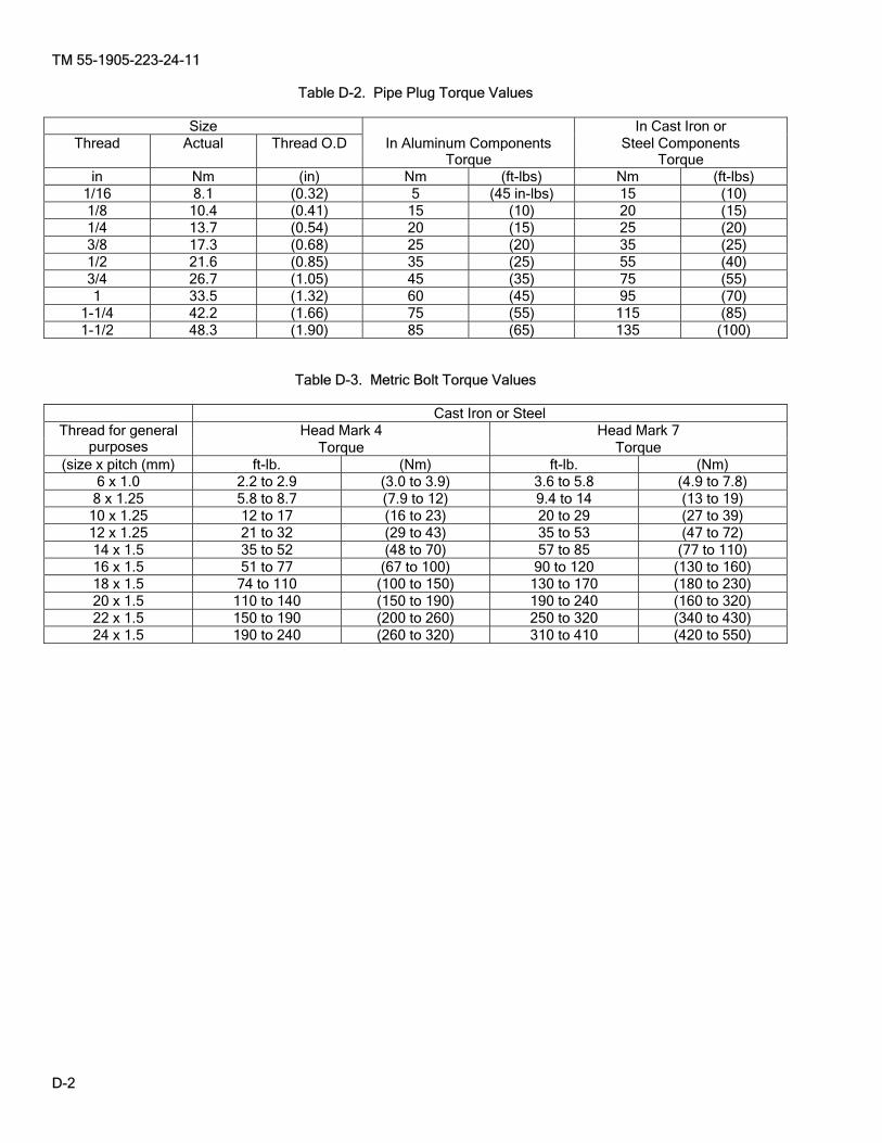
TM 55-1905-223-24-11
D-2
Table D-2. Pipe Plug Torque Values
Size In Cast Iron or Thread Actual Thread O.D In Aluminum Components Steel Components
Torque Torque in Nm (in) Nm (ft-lbs) Nm (ft-lbs)
1/16 8.1 (0.32) 5 (45 in-lbs) 15 (10) 1/8 10.4 (0.41) 15 (10) 20 (15) 1/4 13.7 (0.54) 20 (15) 25 (20) 3/8 17.3 (0.68) 25 (20) 35 (25) 1/2 21.6 (0.85) 35 (25) 55 (40) 3/4 26.7 (1.05) 45 (35) 75 (55) 1 33.5 (1.32) 60 (45) 95 (70)
1-1/4 42.2 (1.66) 75 (55) 115 (85) 1-1/2 48.3 (1.90) 85 (65) 135 (100)
Table D-3. Metric Bolt Torque Values
Cast Iron or Steel Head Mark 4 Head Mark 7 Thread for general
purposes Torque Torque (size x pitch (mm) ft-lb. (Nm) ft-lb. (Nm)
6 x 1.0 2.2 to 2.9 (3.0 to 3.9) 3.6 to 5.8 (4.9 to 7.8) 8 x 1.25 5.8 to 8.7 (7.9 to 12) 9.4 to 14 (13 to 19)
10 x 1.25 12 to 17 (16 to 23) 20 to 29 (27 to 39) 12 x 1.25 21 to 32 (29 to 43) 35 to 53 (47 to 72) 14 x 1.5 35 to 52 (48 to 70) 57 to 85 (77 to 110) 16 x 1.5 51 to 77 (67 to 100) 90 to 120 (130 to 160) 18 x 1.5 74 to 110 (100 to 150) 130 to 170 (180 to 230) 20 x 1.5 110 to 140 (150 to 190) 190 to 240 (160 to 320) 22 x 1.5 150 to 190 (200 to 260) 250 to 320 (340 to 430) 24 x 1.5 190 to 240 (260 to 320) 310 to 410 (420 to 550)

TM 55-1905-223-24-11
Glossary-1
GLOSSARY
SECTION I. ABBREVIATIONS
ABBREVIATION DEFINITION ac........................................................................................................................Alternating Current FNPT..................................................................................................................Female National Pipe Thread ft-lbs....................................................................................................................Foot-pounds H2S .....................................................................................................................Hydrogen Sulfide in-lbs...................................................................................................................Inch-pounds kPA.....................................................................................................................Kilopascal kva......................................................................................................................Kilovolt Amperes LED ....................................................................................................................Light Emitting Diode MSD ...................................................................................................................Marine Sanitation Device psi.......................................................................................................................Pounds Per Square Inch PVC....................................................................................................................Polyvinylchloride plastic RPM ...................................................................................................................Revolutions Per Minute RPSTL................................................................................................................Repair Parts and Special Tools List SO2 ...............................................................................................................................Sulfur Dioxide vdc......................................................................................................................Volts Direct Current VAC....................................................................................................................Volts Alternating Current
SECTION II. DEFINITIONS OF UNUSUAL TERMS
TERM
DEFINITION
ANODE A corrosion preventive zinc plug used for reducing the effects of electrolysis on other metals.
BACKWASH A reversal of liquid flow for the purpose of clearing or unclogging a screen or filter.
BLACKWATER Waste of human origin from water closets and urinals that is transported by the ship sewage system.
CAPACITOR A device possessing the property of capacitance. A typical capacitor consists of two conducting surfaces separated by an insulating material. A capacitor stores electrical energy, blocks the flow of dc current and permits the flow of ac current to a degree largely dependent on the capacitance and the frequency of the applied ac current.
CHLORINATION The process of adding sodium hypochlorite (chlorine bleach) to the treatment unit.
CIRCUIT An electrical path through which an electric current may flow from a voltage supply to a load and return. A closed or complete circuit is one where current is flowing. An open circuit is one where the path has been disrupted, such as an open switch or circuit breaker, thus stopping current flow.
CIRCUIT BREAKER A protective device for opening a circuit when current flow exceeds a predetermined value.
EFFLUENT Treated and processed sewage.
ELECTROLYSIS The decomposition into ions of a chemical compound in solution by the action of an electric current passing through the solution.
GRAYWATER Discarded water from deck drains, lavatories, showers, dishwashers, laundries, and garbage grinders as well as discarded water from shipboard medical facilities. Graywater does not include industrial waste, infectious waste, and/or human body waste.

TM 55-1905-223-24-11
Glossary-2
DEFINITIONS OF UNUSUAL TERMS
TERM
DEFINITION
JUNCTION BOX Main electrical box on a piece of equipment where the electrical power supply is connected to other components on the equipment. Another term for Control Module Assembly.
MACERATOR
A waste disposal unit for the purpose of chopping, cutting, or shredding waste material.
METERING VALVE A valve which allows a preset quantity of a liquid to pass through over a certain period of time.
MODE A method of operation.
MULTIMETER An instrument designed to measure electrical potential (voltage, current, and resistance).
RELAY An electromechanical device having a magnetic coil which, when energized, opens or closes several sets of contacts.
RUNOFF Small amounts of a liquid that may have settled in hoses and lines and will be expelled when connections in the hoses or lines are loosened or disconnected.
SEDIMENTATION Treatment tanks that allow for the settlement of materials MODULE (s) which have not been totally processed for discharge.
SEWAGE Human waste material.
SLUDGE The material which has not been totally processed and has settled in the sedimentation modules (treatment tanks). This material is returned to the macerator for reprocessing.
SODIUM HYPOCHLORITE
Common household type bleach.
SOLENOID An electromechanical device which, when energized, acts on a movable core or plunger in the center of the energizing coil to perform mechanical work.
VOLTMETER An instrument designed to measure electrical potential or voltage.

TM 55-1905-223-24-11
Index-1
ALPHABETICAL INDEX Subject, Paragraph Subject, Paragraph
A Administrative Storage, 2-25, 3-9
B Backwash Piping Assembly Group, 2-20 Inspect, 2-20 Repair, 2-20 Replace, 2-20 Bleach Tank Assembly, 2-23 Inspect, 2-23 Repair, 2-23 Replace, 2-23 Service, 2-23
C Characteristics, Capabilities and Features, 1-6 Checking Unpacked Equipment, 2-4, 3-4 Common Tools and Equipment, 2-1, 3-1 Commode Warning Light Assembly, 2-24 Repair, 2-24 Replace, 2-24 Control Panel Assembly Group, 2-12 Inspect, 2-12 Repair, 2-12 Replace, 2-12 Test, 2-12 Control Panel and Module, 2-13 Inspect, 2-13 Repair, 2-13 Replace, 2-13 Service, 2-13 Test, 2-13
D Destruction of Army Materiel, 1-3 Deprocessing Unpacked Equipment, 2-5 Device Installation Checks, 2-6.a Drain MSD Procedure, 2-6g
E Emergency Operation, 2-6e Equipment Data, 1-8 Equipment Routing Cable Assembly, 2-14 Inspect, 2-14 Repair, 2-14 Replace, 2-14 Explanation of PMCS Table, 2-7, 3-5 Expendable/Durable Supplies and Materials List Explanation of Columns, C-2 Scope, C-1
F Flow Piping Assembly 2-22 Inspect, 2-22 Repair, 2-22 Replace, 2-22 Flow Pump Assembly, 2-19 Inspect, 2-19 Repair, 2-19 Replace, 2-19 Service, 2-19 Test, 2-19 Flushing MSD System, 2-6h Functional Description of Components, 1-12
H Hardware Interface, 1-13
I Impact Sprinkler/Backwash Nozzles, 2-21 Replace, 2-21 Initial Start-Up Procedure, 2-6c Intermediate Direct Support Maintenance Procedures,General, 3-7
L Level Sensor Assembly, 2-17 Inspect, 2-17 Repair, 2-17 Replace, 2-17 Service, 2-17 Test, 2-17 Location and Description of Major Components, 1-7
M Macerator Pump Assembly, 2-18, 3-8 Inspect, 2-18, Repair, 2-18, 3-8 Replace, 2-18 Service, 2-18, 3-8 Test, 2-18, 3-8 Maintenance Allocation Chart (MAC) Explanation of Columns in the MAC, B-3 Explanation of Columns in Remarks, B-5 Explanation of Columns in Tool and Test Equipment Requirements, B-4 Maintenance Functions, B-2 The Army Maintenance System MAC, B-1

TM 55-1905-223-24-11
Index-2
Subject, Paragraph Subject, Paragraph Maintenance Forms, Records and Reports, 1-2 Maintenance of MSD, 2-10
N Normal Operation, 2-6d
O Operation, 2-6b
P Preparation for Storage or Shipment, 1-5 Principles of Operation, Functional Description of Components,1-12 General, 1-10 Hardware Interface, 1-13 Software Interface, 1-14 System Functional Description, 1-11
R Repair Parts, 2-3, 3-3 References, Field Manuals, A-2 Forms, A-7 Military Specifications, A-5 Miscellaneous Publications, A-6 Scope, A-1 Technical Bulletins, A-4 Technical Manuals, A-3 Reporting Errors and Recommending Improvements, i Reporting Equipment Improvement Recommendations (EIR), 1-4
S Safety, Care and Handling, 1-9 Scope of Manual, 1-1 Screen Assembly and Tank Top Group, 2-15 Inspect, 2-15 Repair, 2-15 Replace, 2-15 Service, 2-15 Sedimentation Tank Top Assembly, 2-16 Repair, 2-16 Replace, 2-16 Servicing and Adjustment, Preliminary, 2-6 Device Installation Checks, 2-6.a Drain MSD Procedure, 2-6g Emergency Operation, 2-6e Flushing MSD Procedure, 2-6h Initial Start-Up Procedure, 2-6c Operation, 2-6b Normal Operation, 2-6d Shutdown/Storage Procedures 2-6f Special Tools, TMDE, and Support Equipment, 2-2, 3-2 Software Interface, 1-14 System Functional Description, 1-11
T Table of Contents, i Torque Values Scope, D-1 Treatment Assembly, Sewage, 2-11 Troubleshooting, 2-8, 3-6
U Unit Maintenance Procedures General, 2-9

These are the instructions for sending an electronic 2028. The following format must be used if submitting an electronic 2028. The subject line must be exactly the same and all fields must be included; however, only the following fields are mandatory: 1, 3, 4, 5, 6, 7, 8, 9, 10, 13, 15, 16, 17 and 27. From: “Whomever” [email protected] To: [email protected] To: [email protected] Subject:DA Form 2028 1. From: Joe Smith 2. Unit: home 3. Address: 4300 Park 4. City: Hometown 5. St: MO 6. Zip: 77777 7. Date Sent: 19-OCT-93 8. Pub no: 55-1915-200-10 9. Pub Title: TM 10. Publication Date: 11-APR-88 11. Change Number: 12 12. Submitter Rank: MSG 13. Submitter Fname: Joe 14. Submitter Mname: T 15. Submitter Lname: Smith 16. Submitter Phone: 123-123-1234 17. Problem: 1 18. Page: 1 19. Paragraph: 3 20. Line: 4 21. NSN: 5 22. Reference: 6 23. Figure: 7 24. Table: 8 25. Item: 9 26. Total: 123 27. Text: This is the text for the problem below line 27.


RECOMMENDED CHANGES TO PUBLICATIONS AND BLANK FORMS
For use of this form, see AR 25-30; the proponent agency is OAASA
Use Part II (reverse) for Repair Parts and Special Tool Lists (RPSTL) and Supply Catalogs/Supply Manuals (SC/SM).
DATE
TO (Forward to proponent of publication or form) (Include ZIP Code) FROM (Activity and location) (Include ZIP Code)
PART I – ALL PUBLICATIONS (EXCEPT RPSTL AND SC/SM) AND BLANK FORMS
PUBLICATION/FORM NUMBER TM 55-1905-223-24-11
DATE08 Feb 08
TITLEMARINE SANITATION DEVICE FOR LANDING CRAFT UTILITY NSN 1905-01-154-1191
ITEM PAGE PARA-GRAPH
LINE FIGURE NO.
TABLE RECOMMENDED CHANGES AND REASON
* Reference to line numbers within the paragraph or subparagraph.
TYPED NAME, GRADE OR TITLE TELEPHONE EXCHANGE/AUTOVON, PLUS EXTENSION
SIGNATURE
DA FORM 2028, FEB 74 REPLACES DA FORM 2028, 1 DEC 68, WHICH WILL BE USED. USAPA V3.01
AMSTA-LC-LMPP/TECH PUBS, TACOM-RI1 Rock Island ArsenalRock Island, IL 61299-7630

TO (Forward direct to addressee listed in publication) FROM (Activity and location) (Include ZIP Code) DATE
PART II – REPAIR PARTS AND SPECIAL TOOL LISTS AND SUPPLY CATALOGS/SUPPLY MANUALS
PUBLICATION NUMBER TM 55-1905-223-24-11
DATE08 Feb 08
TITLEMARINE SANITATION DEVICE FOR LANDING CRAFT UTILITY NSN 1905-01-154-1191
PAGE NO.
COLMNO.
LINENO.
NATIONAL STOCK NUMBER
REFERENCE NO.
FIGURE NO.
ITEMNO.
TOTAL NO. OF MAJOR
ITEMSSUPPORTED
RECOMMENDED ACTION
PART III – REMARKS (Any general remarks, recommendations, or suggestions for improvement of publications and blank forms. Additional blank sheets may be used if more space is needed.)
TYPED NAME, GRADE OR TITLE TELEPHONE EXCHANGE/AUTOVON, PLUS EXTENSION
SIGNATURE
USAPA V3.01
AMSTA-LC-LMPP/TECH PUBS TACOM-RI1 Rock Island ArsenalRock Island, IL 61299-7630

RECOMMENDED CHANGES TO PUBLICATIONS AND BLANK FORMS
For use of this form, see AR 25-30; the proponent agency is OAASA
Use Part II (reverse) for Repair Parts and Special Tool Lists (RPSTL) and Supply Catalogs/Supply Manuals (SC/SM).
DATE
TO (Forward to proponent of publication or form) (Include ZIP Code) FROM (Activity and location) (Include ZIP Code)
PART I – ALL PUBLICATIONS (EXCEPT RPSTL AND SC/SM) AND BLANK FORMS
PUBLICATION/FORM NUMBER TM 55-1905-223-24-11
DATE08 Feb 08
TITLEMARINE SANITATION DEVICE FOR LANDING CRAFT UTILITY NSN 1905-01-154-1191
ITEM PAGE PARA-GRAPH
LINE FIGURE NO.
TABLE RECOMMENDED CHANGES AND REASON
* Reference to line numbers within the paragraph or subparagraph.
TYPED NAME, GRADE OR TITLE TELEPHONE EXCHANGE/AUTOVON, PLUS EXTENSION
SIGNATURE
DA FORM 2028, FEB 74 REPLACES DA FORM 2028, 1 DEC 68, WHICH WILL BE USED. USAPA V3.01
AMSTA-LC-LMPP/TECH PUBS, TACOM-RI1 Rock Island Arsenal, Rock Island, IL 61299-7630

TO (Forward direct to addressee listed in publication) FROM (Activity and location) (Include ZIP Code) DATE
PART II – REPAIR PARTS AND SPECIAL TOOL LISTS AND SUPPLY CATALOGS/SUPPLY MANUALS
PUBLICATION NUMBER TM 55-1905-223-24-11
DATE08 Feb 08
TITLEMARINE SANITATION DEVICE FOR LANDING CRAFT UTILITY NSN 1905-01-154-1191
PAGE NO.
COLMNO.
LINENO.
NATIONAL STOCK NUMBER
REFERENCE NO.
FIGURE NO.
ITEMNO.
TOTAL NO. OF MAJOR
ITEMSSUPPORTED
RECOMMENDED ACTION
PART III – REMARKS (Any general remarks, recommendations, or suggestions for improvement of publications and blank forms. Additional blank sheets may be used if more space is needed.)
TYPED NAME, GRADE OR TITLE TELEPHONE EXCHANGE/AUTOVON, PLUS EXTENSION
SIGNATURE
USAPA V3.01
AMSTA-LC-LMPP/TECH PUBS, TACOM-RI1 Rock Island ArsenalRock Island, IL 61299-7630

RECOMMENDED CHANGES TO PUBLICATIONS AND BLANK FORMS
For use of this form, see AR 25-30; the proponent agency is OAASA
Use Part II (reverse) for Repair Parts and Special Tool Lists (RPSTL) and Supply Catalogs/Supply Manuals (SC/SM).
DATE
TO (Forward to proponent of publication or form) (Include ZIP Code) FROM (Activity and location) (Include ZIP Code)
PART I – ALL PUBLICATIONS (EXCEPT RPSTL AND SC/SM) AND BLANK FORMS
PUBLICATION/FORM NUMBER TM 55-1905-223-24-11
DATE08 Feb 08
TITLEMARINE SANITATION DEVICE FOR LANDING CRAFT UTILITY NSN 1905-01-154-1191
ITEM PAGE PARA-GRAPH
LINE FIGURE NO.
TABLE RECOMMENDED CHANGES AND REASON
* Reference to line numbers within the paragraph or subparagraph.
TYPED NAME, GRADE OR TITLE TELEPHONE EXCHANGE/AUTOVON, PLUS EXTENSION
SIGNATURE
DA FORM 2028, FEB 74 REPLACES DA FORM 2028, 1 DEC 68, WHICH WILL BE USED. USAPA V3.01
AMSTA-LC-LMPP/TECH PUBS, TACOM-RI1 Rock Island Arsenal, Rock Island, IL 61299-7630
TO (Forward direct to addressee listed in publication) FROM (Activity and location) (Include ZIP Code) DATE
PART II – REPAIR PARTS AND SPECIAL TOOL LISTS AND SUPPLY CATALOGS/SUPPLY MANUALS
PUBLICATION NUMBER TM 55-1905-223-24-11
DATE08 Feb 08
TITLEMARINE SANITATION DEVICE FOR LANDING CRAFT UTILITY NSN 1905-01-154-1191
PAGE NO.
COLMNO.
LINENO.
NATIONAL STOCK NUMBER
REFERENCE NO.
FIGURE NO.
ITEMNO.
TOTAL NO. OF MAJOR
ITEMSSUPPORTED
RECOMMENDED ACTION
PART III – REMARKS (Any general remarks, recommendations, or suggestions for improvement of publications and blank forms. Additional blank sheets may be used if more space is needed.)
TYPED NAME, GRADE OR TITLE TELEPHONE EXCHANGE/AUTOVON, PLUS EXTENSION
SIGNATURE
USAPA V3.01
AMSTA-LC-LMPP/TECH PUBS, TACOM-RI1 Rock Island Arsenal
Rock Island, IL 61299-7630

By Order of the Secretary of the Army:
DISTRIBUTION: To be distributed in accordance with the Initial Distribution Number (IDN) 254809, requirements for TM 55-1905-223-24-11.
GEORGE W. CASEY, JR. General, United States Army
Chief of Staff Official:
0801608
JOYCE E. MORROW Administrative Assistant to the
Secretary of the Army

The Metric System and Equivalents Linear Measure
1 centimeter = 10 millimeters = .39 inch 1 decimeter = 10 centimeters = 3.94 inches 1 meter = 10 decimeters = 39.37 inches 1 dekameter = 10 meters = 32.8 feet 1 hectometer = 10 dekameters = 328.08 feet 1 kilometer = 10 hectometers = 3,280.8 feet
Weights
1 centigram = 10 milligrams = .15 grain 1 decigram = 10 centigrams = 1.54 grains 1 gram = 10 decigram = .035 ounce 1 dekagram = 10 grams = .35 ounce 1 hectogram = 10 dekagrams = 3.52 ounces 1 kilogram = 10 hectograms = 2.2 pounds 1 quintal = 100 kilograms = 220.46 pounds 1 metric ton = 10 quintals = 1.1 short tons
Liquid Measure
1 centiliter = 10 milliliters = .34 fl. ounce 1 deciliter = 10 centiliters = 3.38 fl. ounces 1 liter = 10 deciliters = 33.81 fl. ounces 1 dekaliter = 10 liters = 2.64 gallons 1 hectoliter = 10 dekaliters = 26.42 gallons 1 kiloliter = 10 hectoliters = 264.18 gallons
Square Measure
1 sq. centimeter = 100 sq. millimeters = .155 sq. inch 1 sq. decimeter = 100 sq. centimeters = 15.5 sq. inches 1 sq. meter (centare) = 100 sq. decimeters = 10.76 sq. feet 1 sq. dekameter (are) = 100 sq. meters – 1,076.4 sq. feet 1 sq. hectometer (hectare) = 100 sq. dekameters = 2.47 acres 1 sq. kilometer = 100 sq. hectometers = .386 sq. mile
Cubic Measure
1 cu. centimeter = 1000 cu. millimeters = .06 cu. inch 1 cu. decimeter = 1000 cu. centimeters = 61.02 cu. inches 1 cu. meter = 1000 cu. decimeters = 35.31 cu. feet
Approximate Conversion Factors
To change To Multiply by To change To Multiply by
inches centimeters 2.540 ounce-inches newton-meters .007062 feet meters .305 centimeters inches .394 yards meters .914 meters feet 3.280 miles kilometers 1.609 meters yards 1.094 square inches square centimeters 6.451 kilometers miles .621 square feet square meters .983 square centimeters square inches .155 square yards square meters .836 square meters square feet 10.764 square miles square kilometers 2.590 square meters square yards 1.196 acres square hectometers .405 square kilometers square miles .386 cubic feet cubic meters .028 square hectometers acres 2.471 cubic yards cubic meters .765 cubic meters cubic feet 35.315 fluid ounces milliliters 29.573 cubic meters cubic yards 1.308 pints liters .473 milliliters fluid ounces .034 quarts liters .946 liters pints 2.113 gallons liters 3.785 liters quarts 1.057 ounces grams 28.349 liters gallons .264 pounds kilograms .454 grams ounces .035 short tons metric tons .907 kilograms pounds 2.205 pound-feet newton-meters 1.356 metric tons short tons 1.102 pound-inches newton meters .11296
Temperature (Exact)
°F Fahrenheit 5/9 (after Celsius °C temperature subtracting 32) temperature

PIN: 065755-000

This fine document...
Was brought to you by me:
Liberated Manuals -- free army and government manuals
Why do I do it? I am tired of sleazy CD-ROM sellers, who take publicly available information, slap “watermarks” and other junk on it, and sell it. Those masters of search engine manipulation make sure that their sites that sell free information, come up first in search engines. They did not create it... They did not even scan it... Why should they get your money? Why are not letting you give those free manuals to your friends?
I am setting this document FREE. This document was made by the US Government and is NOT protected by Copyright. Feel free to share, republish, sell and so on.
I am not asking you for donations, fees or handouts. If you can, please provide a link to liberatedmanuals.com, so that free manuals come up first in search engines:
<A HREF=http://www.liberatedmanuals.com/>Free Military and Government Manuals</A>
– SincerelyIgor Chudovhttp://igor.chudov.com/
– Chicago Machinery Movers