tm 9-2330-334-13p m1147 fmtv-lhst trailer part 2
TRANSCRIPT
8/14/2019 TM 9-2330-334-13P M1147 FMTV-LHST TRAILER PART 2
http://slidepdf.com/reader/full/tm-9-2330-334-13p-m1147-fmtv-lhst-trailer-part-2 1/147
TM 9-2330-334-13&P
LEFT BLACKOUT TAILLIGHT DOES NOT ILLUMINATE 0027 00
THIS WORK PACKAGE COVERS:Electrical System Troubleshooting
0027 00-1
INITIAL SETUP:
Maintenance LevelField
Tools/Special Tools Tool Kit, Genl Mech (Item 22, WP 0167 00)
Materials/PartsTies, Cable, Plastic (Item 20, WP 0165 00) Wire, Elect, 50 ft (Item 22, WP 0165 00)
Personnel Required Two
Equipment ConditionsTrailer coupled (TM 9-2320-392-10-1)Towing vehicle main light switch set to off
(TM 9-2320-392-10-1).
PROCEDURE
WARNING
Remove rings, bracelets, watches, necklaces, and any other jewelry before workingaround vehicle. Jewelry can catch on equipment and cause injury or short acrosselectrical circuit and cause severe burns or electrical shock. Failure to comply mayresult in injury to personnel.
CAUTION
Use care when testing electrical connectors. Do not damage connector pins or sockets withmultimeter probes. Failure to comply may result in damage to equipment.
NOTEReturn vehicle to mission capable condition and perform (Operational Checkout andTroubleshooting Procedures WP 0013 00) after a corrective action has been performed.
Refer to Electrical Schematic at the end of this chapter as required.

8/14/2019 TM 9-2330-334-13P M1147 FMTV-LHST TRAILER PART 2
http://slidepdf.com/reader/full/tm-9-2330-334-13p-m1147-fmtv-lhst-trailer-part-2 2/147
TM 9-2330-334-13&P
LEFT BLACKOUT TAILLIGHT DOES NOT ILLUMINATE-Continued 0027 00
THIS WORK PACKAGE COVERS:Electrical System Troubleshooting
Table 1: Left Blackout Taillight Does Not Illuminate
0027 00-2
INDICATION/CONDITION DECISION (NO/YES) PROCEDURAL STEPS
1. Is 18-30 VDC present atconnector J258?
No. Repair wire 117 (EM 0195)or replace left rear electricalharness (WP 0064 00).
1. Set multimeter to VDC.
Yes. Replace left rear compositetaillight (WP 0060 00).
2. Remove left rear compositelight from trailer for access(WP 0060 00).
3. Disconnect connector J258from left rear compositetaillight.
4. Connect positive (+) probeof multimeter to connectorJ258.
5. Connect negative (-) probeof multimeter to a knowngood ground.
6. Position main light switch toB.O. MARKER on towingvehicle and note reading onmultimeter.
END OF WORK PACKAGE

8/14/2019 TM 9-2330-334-13P M1147 FMTV-LHST TRAILER PART 2
http://slidepdf.com/reader/full/tm-9-2330-334-13p-m1147-fmtv-lhst-trailer-part-2 3/147
TM 9-2330-334-13&P
LEFT BLACKOUT STOPLIGHT DOES NOT ILLUMINATE 0028 00
THIS WORK PACKAGE COVERS:Electrical System Troubleshooting
0028 00-1
INITIAL SETUP:
Maintenance LevelField
Tools/Special Tools Tool Kit, Genl Mech (Item 22, WP 0167 00)
Materials/PartsTies, Cable, Plastic (Item 20, WP 0165 00) Wire, Elect, 50 ft (Item 22, WP 0165 00)
Personnel Required Two
Equipment ConditionsTrailer coupled (TM 9-2320-392-10-1)Towing vehicle main light switch set to off
(TM 9-2320-392-10-1).
PROCEDURE
WARNING
Remove rings, bracelets, watches, necklaces, and any other jewelry before workingaround vehicle. Jewelry can catch on equipment and cause injury or short acrosselectrical circuit and cause severe burns or electrical shock. Failure to comply mayresult in injury to personnel.
CAUTION
Use care when testing electrical connectors. Do not damage connector pins or sockets withmultimeter probes. Failure to comply may result in damage to equipment.
NOTEReturn vehicle to mission capable condition and perform (Operational Checkout andTroubleshooting Procedures WP 0013 00) after a corrective action has been performed.
Refer to Electrical Schematic at the end of this chapter as required.

8/14/2019 TM 9-2330-334-13P M1147 FMTV-LHST TRAILER PART 2
http://slidepdf.com/reader/full/tm-9-2330-334-13p-m1147-fmtv-lhst-trailer-part-2 4/147
TM 9-2330-334-13&P
LEFT BLACKOUT STOPLIGHT DOES NOT ILLUMINATE-Continued 0028 00
THIS WORK PACKAGE COVERS:Electrical System Troubleshooting
Table 1: Left Blackout Stoplight Does Not Illuminate
0028 00-2
INDICATION/CONDITION DECISION (NO/YES) PROCEDURAL STEPS
1. Is 18-30 VDC present atconnector J257?
No. Repair wire 116 (EM 0195)or replace left rear electricalharness (WP 0064 00).
1. Set multimeter to VDC.
Yes. Replace left rear compositetaillight (WP 0060 00).
2. Remove left rear compositelight from trailer for access(WP 0060 00).
3. Disconnect connector J257from left rear compositetaillight.
4. Connect positive (+) probeof multimeter to connectorJ257.
5. Connect negative (-) probeof multimeter to a knowngood ground.
6. Position main light switch toB.O. DRIVE on towingvehicle, depress brake pedal,and note reading onmultimeter.
END OF WORK PACKAGE

8/14/2019 TM 9-2330-334-13P M1147 FMTV-LHST TRAILER PART 2
http://slidepdf.com/reader/full/tm-9-2330-334-13p-m1147-fmtv-lhst-trailer-part-2 5/147
TM 9-2330-334-13&P
BOTH BLACKOUT STOPLIGHTS DO NOT ILLUMINATE 0029 00
THIS WORK PACKAGE COVERS:Electrical System Troubleshooting
0029 00-1
INITIAL SETUP:
Maintenance LevelField
Tools/Special Tools Tool Kit, Genl Mech (Item 22, WP 0167 00)
Materials/PartsTies, Cable, Plastic (Item 20, WP 0165 00) Wire, Elect, 50 ft (Item 22, WP 0165 00)
Personnel Required Two
Equipment ConditionsTrailer coupled (TM 9-2320-392-10-1)Towing vehicle main light switch set to off
(TM 9-2320-392-10-1).
PROCEDURE
WARNING
Remove rings, bracelets, watches, necklaces, and any other jewelry before workingaround vehicle. Jewelry can catch on equipment and cause injury or short acrosselectrical circuit and cause severe burns or electrical shock. Failure to comply mayresult in injury to personnel.
CAUTION
Use care when testing electrical connectors. Do not damage connector pins or sockets withmultimeter probes. Failure to comply may result in damage to equipment.
NOTEReturn vehicle to mission capable condition and perform (Operational Checkout andTroubleshooting Procedures WP 0013 00) after a corrective action has been performed.
Refer to Electrical Schematic at the end of this chapter as required.

8/14/2019 TM 9-2330-334-13P M1147 FMTV-LHST TRAILER PART 2
http://slidepdf.com/reader/full/tm-9-2330-334-13p-m1147-fmtv-lhst-trailer-part-2 6/147
TM 9-2330-334-13&P
BOTH BLACKOUT STOPLIGHTS DO NOT ILLUMINATE-Continued 0029 00
ELECTRICAL SYSTEM TROUBLESHOOTING - Continued
Table 1. Both Blackout Stoplights Do Not Illuminate
0029 00-2
INDICATION/CONDITION DECISION (NO/YES) PROCEDURAL STEPS
1. Is 18-30 VDC present atintervehicular cable pin F?
No. Replace intervehicular cable(WP 0062 00).
1. Set multimeter to VDC.
Yes. Go to (Indication/Condition2).
2. Disconnect intervehicularcable connector fromvoltage converter box.
3. Position main light switch toB.O. DRIVE on towingvehicle and depress brakepeddle.
4. Connect positive (+) probeof multimeter tointervehicular cable pin F.
5. Connect negative (-) probeof multimeter to a knowngood ground and notereading on multimeter.
6. Position main light switch to ALL OFF.

8/14/2019 TM 9-2330-334-13P M1147 FMTV-LHST TRAILER PART 2
http://slidepdf.com/reader/full/tm-9-2330-334-13p-m1147-fmtv-lhst-trailer-part-2 7/147
TM 9-2330-334-13&P
BOTH BLACKOUT STOPLIGHTS DO NOT ILLUMINATE-Continued 0029 00
ELECTRICAL SYSTEM TROUBLESHOOTING - Continued
Table 1. Both Blackout Stoplights Do Not Illuminate
0029 00-3
INDICATION/CONDITION DECISION (NO/YES) PROCEDURAL STEPS
2. Is continuity present acrosscircuit breaker CB2?
No. Replace circuit breaker CB2(WP 0057 00).
1. Set multimeter to ohms.
Yes. Go to (Indication/Condition3).
2. Remove two screws andopen voltage converter box.
3. Connect positive (+) probeof multimeter to oneterminal on circuit breakerCB2.
4. Connect negative (-) probeof multimeter to otherterminal on circuit breakerCB2 and note reading onmultimeter.

8/14/2019 TM 9-2330-334-13P M1147 FMTV-LHST TRAILER PART 2
http://slidepdf.com/reader/full/tm-9-2330-334-13p-m1147-fmtv-lhst-trailer-part-2 8/147
TM 9-2330-334-13&P
BOTH BLACKOUT STOPLIGHTS DO NOT ILLUMINATE-Continued 0029 00
ELECTRICAL SYSTEM TROUBLESHOOTING - Continued
Table 1. Both Blackout Stoplights Do Not Illuminate
0029 00-4
INDICATION/CONDITION DECISION (NO/YES) PROCEDURAL STEPS
3. Is 18-30 VDC present atTL257?
No. Repair wire or replacevoltage converter box (WP0058 00).
1. Set multimeter to VDC.
Yes. Repair wire 104 (EM 0195)or replace main electricalharness (WP 0066 00).
2. Connect intervehicular cableconnector to voltageconverter box.
3. Position main light switch toB.O. DRIVE on towingvehicle and depress brake
pedal.
4. Connect positive (+) probeof multimeter to TL257.
5. Connect negative (-) probeof multimeter to a knowngood ground and notereading on multimeter.
END OF WORK PACKAGE

8/14/2019 TM 9-2330-334-13P M1147 FMTV-LHST TRAILER PART 2
http://slidepdf.com/reader/full/tm-9-2330-334-13p-m1147-fmtv-lhst-trailer-part-2 9/147
TM 9-2330-334-13&P
ALL LIGHTS DO NOT ILLUMINATE 0030 00
THIS WORK PACKAGE COVERS:Electrical System Troubleshooting
0030 00-1
INITIAL SETUP:
Maintenance LevelField
Tools/Special Tools Tool Kit, Genl Mech (Item 22, WP 0167 00)
Materials/PartsTies, Cable, Plastic (Item 20, WP 0165 00) Wire, Elect, 50 ft (Item 22, WP 0165 00)
Personnel Required Two
Equipment ConditionsTrailer coupled (TM 9-2320-392-10-1)Towing vehicle main light switch set to off
(TM 9-2320-392-10-1).
PROCEDURE
WARNING
Remove rings, bracelets, watches, necklaces, and any other jewelry before workingaround vehicle. Jewelry can catch on equipment and cause injury or short acrosselectrical circuit and cause severe burns or electrical shock. Failure to comply mayresult in injury to personnel.
CAUTION
Use care when testing electrical connectors. Do not damage connector pins or sockets withmultimeter probes. Failure to comply may result in damage to equipment.
NOTEReturn vehicle to mission capable condition and perform (Operational Checkout andTroubleshooting Procedures WP 0013 00) after a corrective action has been performed.
Refer to Electrical Schematic at the end of this chapter as required.
Remove plastic cable ties as required.

8/14/2019 TM 9-2330-334-13P M1147 FMTV-LHST TRAILER PART 2
http://slidepdf.com/reader/full/tm-9-2330-334-13p-m1147-fmtv-lhst-trailer-part-2 10/147
TM 9-2330-334-13&P
ALL LIGHTS DO NOT ILLUMINATE-Continued 0030 00
ELECTRICAL SYSTEM TROUBLESHOOTING - Continued
Table 1. All Lights Do Not Illuminate
0030 00-2
INDICATION/CONDITION DECISION (NO/YES) PROCEDURAL STEPS
1. Is 18-30 VDC present atintervehicular cable pin E?
No. Replace intervehicular cable(WP 0062 00).
1. Set multimeter to VDC.
Yes. Replace voltage converterbox (WP 0058 00).
2. Disconnect intervehicularcable connector fromvoltage converter box.
3. Connect positive (+) probeof multimeter tointervehicular cable pin E.
4. Connect negative (-) probeof multimeter to a knowngood ground.
5. Position main light switch toSER DRIVE on towingvehicle and note reading onmultimeter.
END OF WORK PACKAGE

8/14/2019 TM 9-2330-334-13P M1147 FMTV-LHST TRAILER PART 2
http://slidepdf.com/reader/full/tm-9-2330-334-13p-m1147-fmtv-lhst-trailer-part-2 11/147
TM 9-2330-334-13&P
ANTI-LOCK BRAKE SYSTEM (ABS) DIAGNOSTICLIGHT DOES NOT OPERATE 0031 00
THIS WORK PACKAGE COVERS:Brakes System Troubleshooting
0031 00-1
INITIAL SETUP:
Maintenance LevelField
Tools/Special Tools Tool Kit, Genl Mech (Item 22, WP 0167 00)
Materials/PartsTies, Cable, Plastic (Item 20, WP 0165 00) Wire, Elect, 50 ft (Item 22, WP 0165 00)
Personnel Required Two
Equipment Conditions24 VDC intervehicular cable connected to
towing vehicle (TM 9-2320-392-10-1).
PROCEDURE
WARNING
Remove rings, bracelets, watches, necklaces, and any other jewelry before workingaround vehicle. Jewelry can catch on equipment and cause injury or short acrosselectrical circuit and cause severe burns or electrical shock. Failure to comply mayresult in injury to personnel.
CAUTION
Use care when testing electrical connectors. Do not damage connector pins or sockets withmultimeter probes. Failure to comply may result in damage to equipment.
NOTEReturn vehicle to mission capable condition and perform (Operational Checkout andTroubleshooting Procedures WP 0013 00) after a corrective action has been performed.
Refer to Electrical Schematic at the end of this chapter as required.

8/14/2019 TM 9-2330-334-13P M1147 FMTV-LHST TRAILER PART 2
http://slidepdf.com/reader/full/tm-9-2330-334-13p-m1147-fmtv-lhst-trailer-part-2 12/147
TM 9-2330-334-13&P
ANTI-LOCK BRAKE SYSTEM (ABS) DIAGNOSTICLIGHT DOES NOT OPERATE-Continued 0031 00
BRAKE SYSTEM TROUBLESHOOTING - Continued
Table 1. Anti-Lock Brake System (ABS) Diagnostic Light Does Not Operate
0031 00-2
INDICATION/CONDITION DECISION (NO/YES) PROCEDURAL STEPS
1. Is 8-16 VDC present atterminal lug TL612 of ABSdiagnostic light electricalharness?
No. Go to (Indication/Condition3).
1. Set multimeter to VDC.
Yes. Go to (Indication/Condition2).
2. Disconnect terminal lugTL612 from ABS diagnosticlight lead.
3. Connect positive (+) probe
of multimeter to terminal lugTL612.
4. Connect negative (-) probeof multimeter to a knowngood ground.
5. Position towing vehiclemaster power switch to onand note reading onmultimeter.
8/14/2019 TM 9-2330-334-13P M1147 FMTV-LHST TRAILER PART 2
http://slidepdf.com/reader/full/tm-9-2330-334-13p-m1147-fmtv-lhst-trailer-part-2 13/147
TM 9-2330-334-13&P
ANTI-LOCK BRAKE SYSTEM (ABS) DIAGNOSTICLIGHT DOES NOT OPERATE-Continued 0031 00
BRAKE SYSTEM TROUBLESHOOTING - Continued
Table 1. Anti-Lock Brake System (ABS) Diagnostic Light Does Not Operate
0031 00-3
INDICATION/CONDITION DECISION (NO/YES) PROCEDURAL STEPS
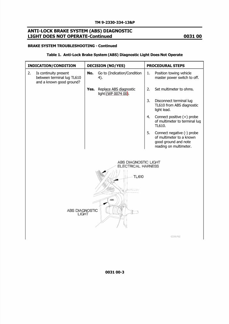
2. Is continuity presentbetween terminal lug TL610and a known good ground?
No. Go to (Indication/Condition4).
1. Position towing vehiclemaster power switch to off.
Yes. Replace ABS diagnosticlight (WP 0074 00).
2. Set multimeter to ohms.
3. Disconnect terminal lugTL610 from ABS diagnosticlight lead.
4. Connect positive (+) probeof multimeter to terminal lugTL610.
5. Connect negative (-) probeof multimeter to a knowngood ground and notereading on multimeter.

8/14/2019 TM 9-2330-334-13P M1147 FMTV-LHST TRAILER PART 2
http://slidepdf.com/reader/full/tm-9-2330-334-13p-m1147-fmtv-lhst-trailer-part-2 14/147

8/14/2019 TM 9-2330-334-13P M1147 FMTV-LHST TRAILER PART 2
http://slidepdf.com/reader/full/tm-9-2330-334-13p-m1147-fmtv-lhst-trailer-part-2 15/147
TM 9-2330-334-13&P
ANTI-LOCK BRAKE SYSTEM (ABS) DIAGNOSTICLIGHT DOES NOT OPERATE-Continued 0031 00
BRAKE SYSTEM TROUBLESHOOTING - Continued
Table 1. Anti-Lock Brake System (ABS) Diagnostic Light Does Not Operate
0037 00-5
INDICATION/CONDITION DECISION (NO/YES) PROCEDURAL STEPS
4. Is continuity presentbetween junction box stud 1and a known good ground?
No. Replace junction box (WP0059 00).
1. Position towing vehiclemaster power switch to off.
Yes. Replace ABS diagnosticlight harness (WP 007700).
2. Set multimeter to ohms.
3. Connect positive (+) probeof multimeter to junction box
stud 1.
4. Connect negative (-) probeof multimeter to a knowngood ground and notereading on multimeter.
8/14/2019 TM 9-2330-334-13P M1147 FMTV-LHST TRAILER PART 2
http://slidepdf.com/reader/full/tm-9-2330-334-13p-m1147-fmtv-lhst-trailer-part-2 16/147
TM 9-2330-334-13&P
ANTI-LOCK BRAKE SYSTEM (ABS) DIAGNOSTICLIGHT DOES NOT OPERATE-Continued 0031 00
BRAKE SYSTEM TROUBLESHOOTING - Continued
Table 1. Anti-Lock Brake System (ABS) Diagnostic Light Does Not Operate
0031 00-6
INDICATION/CONDITION DECISION (NO/YES) PROCEDURAL STEPS
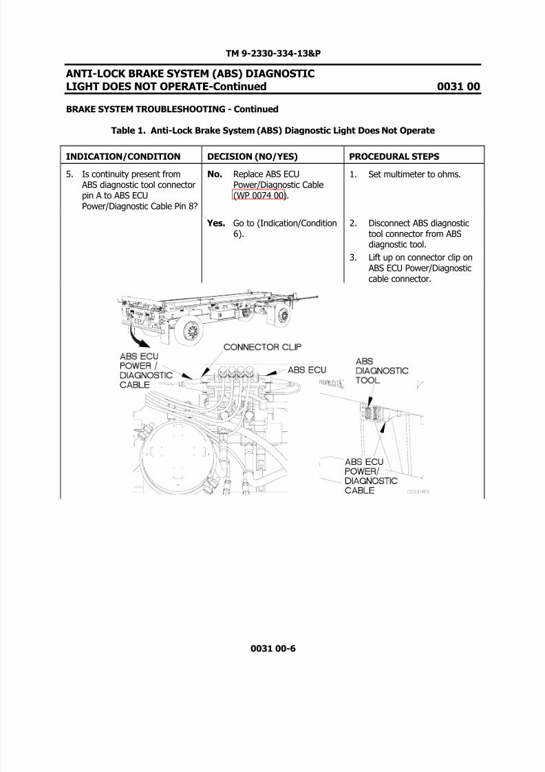
5. Is continuity present from ABS diagnostic tool connectorpin A to ABS ECUPower/Diagnostic Cable Pin 8?
No. Replace ABS ECUPower/Diagnostic Cable(WP 0074 00).
1. Set multimeter to ohms.
Yes. Go to (Indication/Condition6).
2. Disconnect ABS diagnostictool connector from ABSdiagnostic tool.
3. Lift up on connector clip on
ABS ECU Power/Diagnosticcable connector.

8/14/2019 TM 9-2330-334-13P M1147 FMTV-LHST TRAILER PART 2
http://slidepdf.com/reader/full/tm-9-2330-334-13p-m1147-fmtv-lhst-trailer-part-2 17/147
TM 9-2330-334-13&P
ANTI-LOCK BRAKE SYSTEM (ABS) DIAGNOSTICLIGHT DOES NOT OPERATE-Continued 0031 00
BRAKE SYSTEM TROUBLESHOOTING - Continued
Table 1. Anti-Lock Brake System (ABS) Diagnostic Light Does Not Operate
0031 00-7
INDICATION/CONDITION DECISION (NO/YES) PROCEDURAL STEPS
5. Is continuity present from ABS diagnostic toolconnector pin A to ABS ECUPower/Diagnostic Cable Pin8? (Cont)
No. Replace ABS ECUPower/Diagnostic Cable(WP 0074 00).
4. Disconnect ABS ECUPower/Diagnostic cable from ABS ECU.
Yes. Go to (Indication/Condition6).
5. Connect positive (+) probeof multimeter to ABSDiagnostic Tool connector
pin A.6. Connect negative (-) probe
of multimeter to ABS ECUPower/Diagnostic cable pin 8and note reading onmultimeter.
8/14/2019 TM 9-2330-334-13P M1147 FMTV-LHST TRAILER PART 2
http://slidepdf.com/reader/full/tm-9-2330-334-13p-m1147-fmtv-lhst-trailer-part-2 18/147
TM 9-2330-334-13&P
ANTI-LOCK BRAKE SYSTEM (ABS) DIAGNOSTICLIGHT DOES NOT OPERATE-Continued 0031 00
BRAKE SYSTEM TROUBLESHOOTING - Continued
Table 1. Anti-Lock Brake System (ABS) Diagnostic Light Does Not Operate
0031 00-8
INDICATION/CONDITION DECISION (NO/YES) PROCEDURAL STEPS
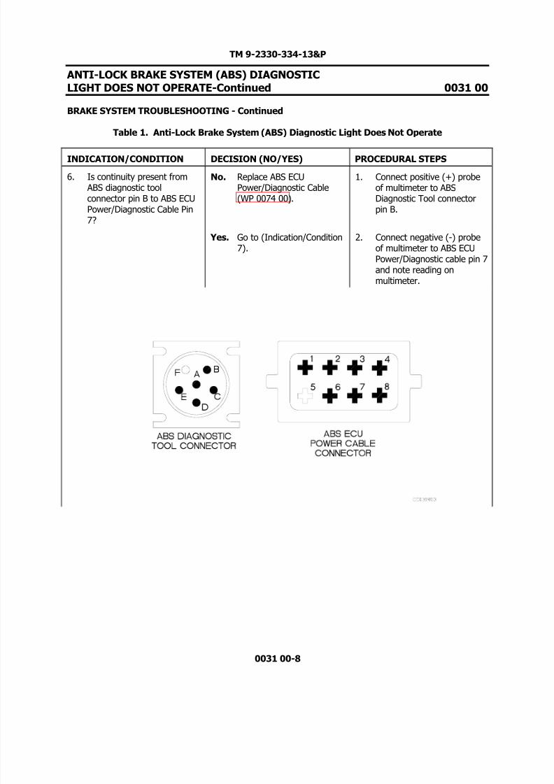
6. Is continuity present from ABS diagnostic toolconnector pin B to ABS ECUPower/Diagnostic Cable Pin7?
No. Replace ABS ECUPower/Diagnostic Cable(WP 0074 00).
1. Connect positive (+) probeof multimeter to ABSDiagnostic Tool connectorpin B.
Yes. Go to (Indication/Condition7).
2. Connect negative (-) probeof multimeter to ABS ECUPower/Diagnostic cable pin 7
and note reading onmultimeter.

8/14/2019 TM 9-2330-334-13P M1147 FMTV-LHST TRAILER PART 2
http://slidepdf.com/reader/full/tm-9-2330-334-13p-m1147-fmtv-lhst-trailer-part-2 19/147
TM 9-2330-334-13&P
ANTI-LOCK BRAKE SYSTEM (ABS) DIAGNOSTICLIGHT DOES NOT OPERATE-Continued 0031 00
BRAKE SYSTEM TROUBLESHOOTING - Continued
Table 1. Anti-Lock Brake System (ABS) Diagnostic Light Does Not Operate
0031 00-9
INDICATION/CONDITION DECISION (NO/YES) PROCEDURAL STEPS
7. Is continuity present from ABS diagnostic toolconnector pin C to ABS ECUPower/Diagnostic Cable Pin6?
No. Replace ABS ECUPower/Diagnostic Cable(WP 0074 00).
1. Connect positive (+) probeof multimeter to ABSDiagnostic Tool connectorpin C.
Yes. Go to (Indication/Condition8).
2. Connect negative (-) probeof multimeter to ABS ECUPower/Diagnostic cable pin 6
and note reading onmultimeter.

8/14/2019 TM 9-2330-334-13P M1147 FMTV-LHST TRAILER PART 2
http://slidepdf.com/reader/full/tm-9-2330-334-13p-m1147-fmtv-lhst-trailer-part-2 20/147
TM 9-2330-334-13&P
ANTI-LOCK BRAKE SYSTEM (ABS) DIAGNOSTICLIGHT DOES NOT OPERATE-Continued 0031 00
BRAKE SYSTEM TROUBLESHOOTING - Continued
Table 1. Anti-Lock Brake System (ABS) Diagnostic Light Does Not Operate
0031 00-10
INDICATION/CONDITION DECISION (NO/YES) PROCEDURAL STEPS
8. Is continuity present from ABS diagnostic toolconnector pin D to ABS ECUPower/Diagnostic Cable Pin1?
No. Replace ABS ECUPower/Diagnostic Cable(WP 0074 00).
1. Connect positive (+) probeof multimeter to ABSDiagnostic Tool connectorpin D.
Yes. Go to (Indication/Condition9).
2. Connect negative (-) probeof multimeter to ABS ECUPower/Diagnostic cable pin 1
and note reading onmultimeter.

8/14/2019 TM 9-2330-334-13P M1147 FMTV-LHST TRAILER PART 2
http://slidepdf.com/reader/full/tm-9-2330-334-13p-m1147-fmtv-lhst-trailer-part-2 21/147
TM 9-2330-334-13&P
ANTI-LOCK BRAKE SYSTEM (ABS) DIAGNOSTICLIGHT DOES NOT OPERATE-Continued 0031 00
BRAKE SYSTEM TROUBLESHOOTING - Continued
Table 1. Anti-Lock Brake System (ABS) Diagnostic Light Does Not Operate
0031 00-11
INDICATION/CONDITION DECISION (NO/YES) PROCEDURAL STEPS
9. Is continuity present from ABS diagnostic toolconnector pin E to ABS ECUPower/Diagnostic Cable Pin4?
No. Replace ABS ECUPower/Diagnostic Cable(WP 0074 00).
1. Connect positive (+) probeof multimeter to ABSDiagnostic Tool connectorpin E.
Yes. Go to (Indication/Condition10).
2. Connect negative (-) probeof multimeter to ABS ECUPower/Diagnostic cable pin 4
and note reading onmultimeter.

8/14/2019 TM 9-2330-334-13P M1147 FMTV-LHST TRAILER PART 2
http://slidepdf.com/reader/full/tm-9-2330-334-13p-m1147-fmtv-lhst-trailer-part-2 22/147
TM 9-2330-334-13&P
ANTI-LOCK BRAKE SYSTEM (ABS) DIAGNOSTICLIGHT DOES NOT OPERATE-Continued 0031 00
BRAKE SYSTEM TROUBLESHOOTING - Continued
Table 1. Anti-Lock Brake System (ABS) Diagnostic Light Does Not Operate
0031 00-12
INDICATION/CONDITION DECISION (NO/YES) PROCEDURAL STEPS
10. Is continuity present from ABS Power/Diagnostic cableblue wire to ABS ECUPower/Diagnostic Cable pin3?
No. Replace ABS ECUPower/Diagnostic Cable(WP 0074 00).
1. Remove cover on junctionbox for access (WP 005900).
Yes. Go to (Indication/Condition11).
2. Connect positive (+) probeof multimeter to ABSPower/Diagnostic cable blue
wire terminal lug (located onterminal 5 of junction box).
3. Connect negative (-) probeof multimeter to ABS ECUPower/Diagnostic cable pin 3and note reading onmultimeter.
8/14/2019 TM 9-2330-334-13P M1147 FMTV-LHST TRAILER PART 2
http://slidepdf.com/reader/full/tm-9-2330-334-13p-m1147-fmtv-lhst-trailer-part-2 23/147
TM 9-2330-334-13&P
ANTI-LOCK BRAKE SYSTEM (ABS) DIAGNOSTICLIGHT DOES NOT OPERATE-Continued 0031 00
BRAKE SYSTEM TROUBLESHOOTING - Continued
Table 1. Anti-Lock Brake System (ABS) Diagnostic Light Does Not Operate
0031 00-13
INDICATION/CONDITION DECISION (NO/YES) PROCEDURAL STEPS
11. Is 8-16 VDC present atterminal lug TL251A?
No. Go to (Indication/Condition12).
1. Set multimeter to VDC.
Yes. Replace ABS ECU (WP 007100).
2. Connect positive (+) probeof multimeter to terminal lugTL 251A (located on terminal5 in junction box).
3. Connect negative (-) probeof multimeter to a known
good ground.
4. Position master power switchto on and note reading onmultimeter.

8/14/2019 TM 9-2330-334-13P M1147 FMTV-LHST TRAILER PART 2
http://slidepdf.com/reader/full/tm-9-2330-334-13p-m1147-fmtv-lhst-trailer-part-2 24/147
TM 9-2330-334-13&P
ANTI-LOCK BRAKE SYSTEM (ABS) DIAGNOSTICLIGHT DOES NOT OPERATE-Continued 0031 00
BRAKE SYSTEM TROUBLESHOOTING - Continued
Table 1. Anti-Lock Brake System (ABS) Diagnostic Light Does Not Operate
0031 00-14
INDICATION/CONDITION DECISION (NO/YES) PROCEDURAL STEPS
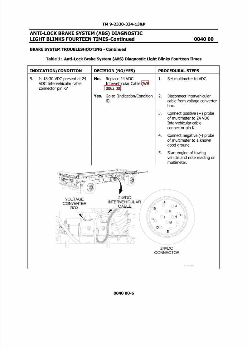
12. Is 18-30 VDC present at 24 VDC intervehicular cable pinK?
No. Replace 24 VDCintervehicular cable (WP0062 00).
1. Position towing vehiclemaster power switch to off.
Yes. Go to (Indication/Condition13).
2. Disconnect 24 VDCintervehicular cable fromvoltage converter box.
3. Connect positive (+) probeof multimeter to 24 VDC
intervehicular cable pin K.
4. Connect negative (-) probeof multimeter to a knowngood ground.
5. Position master power switchto on and note reading onmultimeter.

8/14/2019 TM 9-2330-334-13P M1147 FMTV-LHST TRAILER PART 2
http://slidepdf.com/reader/full/tm-9-2330-334-13p-m1147-fmtv-lhst-trailer-part-2 25/147
TM 9-2330-334-13&P
ANTI-LOCK BRAKE SYSTEM (ABS) DIAGNOSTICLIGHT DOES NOT OPERATE-Continued 0031 00
BRAKE SYSTEM TROUBLESHOOTING - Continued
Table 1. Anti-Lock Brake System (ABS) Diagnostic Light Does Not Operate
0031 00-15/16 Blank
INDICATION/CONDITION DECISION (NO/YES) PROCEDURAL STEPS
13. Is continuity present acrosscircuit breaker CB1?
No. Replace circuit breaker CB1(WP 0057 00).
1. Position towing vehiclemaster power switch to off.
Yes. Replace module 5 (WP0057 00).
2. Set multimeter to ohms.
3. Loosen two screws and openlid of voltage converter box.
4. Connect positive (+) probe
of multimeter to oneterminal of circuit breakerCB1.
5. Connect negative (-) probeof multimeter to otherterminal of circuit breakerCB1 and note reading onmultimeter.

8/14/2019 TM 9-2330-334-13P M1147 FMTV-LHST TRAILER PART 2
http://slidepdf.com/reader/full/tm-9-2330-334-13p-m1147-fmtv-lhst-trailer-part-2 26/147

8/14/2019 TM 9-2330-334-13P M1147 FMTV-LHST TRAILER PART 2
http://slidepdf.com/reader/full/tm-9-2330-334-13p-m1147-fmtv-lhst-trailer-part-2 27/147
TM 9-2330-334-13&P
ANTI-LOCK BRAKE SYSTEM (ABS) DIAGNOSTICLIGHT BLINKS THREE TIMES 0032 00
THIS WORK PACKAGE COVERS:Brake System Troubleshooting
0032 00-1
INITIAL SETUP:
Maintenance LevelField
Tools/Special Tools Tool Kit, Genl Mech (Item 22, WP 0167 00)
Materials/PartsTies, Cable, Plastic (Item 20, WP 0165 00)
Personnel Required Two
Equipment ConditionsTrailer coupled (TM 9-2320-392-10-1).
PROCEDURE
WARNING
Remove rings, bracelets, watches, necklaces, and any other jewelry before workingaround vehicle. Jewelry can catch on equipment and cause injury or short acrosselectrical circuit and cause severe burns or electrical shock. Failure to comply mayresult in injury to personnel.
CAUTION
Use care when testing electrical connectors. Do not damage connector pins or sockets withmultimeter probes. Failure to comply may result in damage to equipment.
Do not pry or push ABS wheel speed sensor with sharp objects. Failure to comply may resultin damage to equipment.
NOTEReturn vehicle to mission capable condition and perform (Operational Checkout andTroubleshooting Procedures WP 0013 00) after a corrective action has been performed.

8/14/2019 TM 9-2330-334-13P M1147 FMTV-LHST TRAILER PART 2
http://slidepdf.com/reader/full/tm-9-2330-334-13p-m1147-fmtv-lhst-trailer-part-2 28/147
TM 9-2330-334-13&P
ANTI-LOCK BRAKE SYSTEM (ABS) DIAGNOSTICLIGHT BLINKS THREE TIMES-Continued 0032 00
BRAKE SYSTEM TROUBLESHOOTING - Continued
Table 1: Anti-Lock Brake System (ABS) Diagnostic Light Blinks Three Times
0032 00-2
INDICATION/CONDITION DECISION (NO/YES) PROCEDURAL STEPS
1. Is blink code still presentafter right rear ABS wheelspeed sensor position isreset?
No. Fault corrected. 1. Push right rear ABS wheelspeed sensor in until itcontacts tooth wheel.
Yes. Go to (Indication/Condition2).
2. Start engine of towingvehicle.
NOTE
Trailer must be operated more than 4 mph (6 km/h) during road test.3. Road test trailer.
4. Park towing vehicle.
5. Press button on ABSdiagnostic tool for 1 second.
6. Check to see if ABSdiagnostic tool and ABSdiagnostic light blink.

8/14/2019 TM 9-2330-334-13P M1147 FMTV-LHST TRAILER PART 2
http://slidepdf.com/reader/full/tm-9-2330-334-13p-m1147-fmtv-lhst-trailer-part-2 29/147
TM 9-2330-334-13&P
ANTI-LOCK BRAKE SYSTEM (ABS) DIAGNOSTICLIGHT BLINKS THREE TIMES-Continued 0032 00
BRAKE SYSTEM TROUBLESHOOTING - Continued
Table 1: Anti-Lock Brake System (ABS) Diagnostic Light Blinks Three Times
0032 00-3
INDICATION/CONDITION DECISION (NO/YES) PROCEDURAL STEPS
2. Is 700-3000 ohms of resistance is present acrossright rear ABS wheel speedsensor.
No. Replace right rear ABSwheel speed sensor (WP0070 00).
1. Set multimeter to ohms.
Yes. Go to (Indication/Condition3).
2. Disconnect right rear ABSwheel speed sensor harnessconnector from ABS wheelspeed sensor.
3. Connect positive (+) probeof multimeter to one socketof ABS wheel speed sensorconnector.
4. Connect negative (-) probeof multimeter to othersocket of ABS wheel speedsensor connector and notereading on multimeter.

8/14/2019 TM 9-2330-334-13P M1147 FMTV-LHST TRAILER PART 2
http://slidepdf.com/reader/full/tm-9-2330-334-13p-m1147-fmtv-lhst-trailer-part-2 30/147

8/14/2019 TM 9-2330-334-13P M1147 FMTV-LHST TRAILER PART 2
http://slidepdf.com/reader/full/tm-9-2330-334-13p-m1147-fmtv-lhst-trailer-part-2 31/147

8/14/2019 TM 9-2330-334-13P M1147 FMTV-LHST TRAILER PART 2
http://slidepdf.com/reader/full/tm-9-2330-334-13p-m1147-fmtv-lhst-trailer-part-2 32/147
TM 9-2330-334-13&P
ANTI-LOCK BRAKE SYSTEM (ABS) DIAGNOSTICLIGHT BLINKS FOUR TIMES-Continued 0033 00
BRAKE SYSTEM TROUBLESHOOTING - Continued
Table 1: Anti-Lock Brake System (ABS) Diagnostic Light Blinks Four Times
0033 00-2
INDICATION/CONDITION DECISION (NO/YES) PROCEDURAL STEPS
1. Is blink code still presentafter left rear ABS wheelspeed sensor position isreset?
No. Fault corrected. 1. Push left rear ABS wheelspeed sensor in until itcontacts tooth wheel.
Yes. Go to (Indication/Condition2).
2. Start engine of towingvehicle.
NOTE
Trailer must be operated more than 4 mph (6 km/h) during road test.3. Road test trailer.
4. Park towing vehicle.
5. Press button on ABSdiagnostic tool for 1 second.
6. Check to see if ABSdiagnostic tool and ABSdiagnostic light blink.

8/14/2019 TM 9-2330-334-13P M1147 FMTV-LHST TRAILER PART 2
http://slidepdf.com/reader/full/tm-9-2330-334-13p-m1147-fmtv-lhst-trailer-part-2 33/147
TM 9-2330-334-13&P
ANTI-LOCK BRAKE SYSTEM (ABS) DIAGNOSTICLIGHT BLINKS FOUR TIMES-Continued 0033 00
BRAKE SYSTEM TROUBLESHOOTING - Continued
Table 1: Anti-Lock Brake System (ABS) Diagnostic Light Blinks Four Times
0033 00-3
INDICATION/CONDITION DECISION (NO/YES) PROCEDURAL STEPS
2. Is 700-3000 ohms of resistance is present acrossleft rear ABS wheel speedsensor.
No. Replace left rear ABS wheelspeed sensor (WP 007000).
1. Set multimeter to ohms.
Yes. Go to (Indication/Condition3).
2. Disconnect left rear ABSwheel speed sensor harnessconnector from ABS wheelspeed sensor.
3. Connect positive (+) probeof multimeter to one socketof ABS wheel speed sensorconnector.
4. Connect negative (-) probeof multimeter to othersocket of ABS wheel speedsensor connector and notereading on multimeter.

8/14/2019 TM 9-2330-334-13P M1147 FMTV-LHST TRAILER PART 2
http://slidepdf.com/reader/full/tm-9-2330-334-13p-m1147-fmtv-lhst-trailer-part-2 34/147

8/14/2019 TM 9-2330-334-13P M1147 FMTV-LHST TRAILER PART 2
http://slidepdf.com/reader/full/tm-9-2330-334-13p-m1147-fmtv-lhst-trailer-part-2 35/147
TM 9-2330-334-13&P
ANTI-LOCK BRAKE SYSTEM (ABS) DIAGNOSTICLIGHT BLINKS FIVE TIMES 0034 00
THIS WORK PACKAGE COVERS:Brake System Troubleshooting
0034 00-1
INITIAL SETUP:
Maintenance LevelField
Tools/Special Tools Tool Kit, Genl Mech (Item 22, WP 0167 00)
Materials/PartsTies, Cable, Plastic (Item 20, WP 0165 00)
Personnel Required Two
Equipment ConditionsTrailer coupled (TM 9-2320-392-10-1).
PROCEDURE
WARNING
Remove rings, bracelets, watches, necklaces, and any other jewelry before workingaround vehicle. Jewelry can catch on equipment and cause injury or short acrosselectrical circuit and cause severe burns or electrical shock. Failure to comply mayresult in injury to personnel.
CAUTION
Use care when testing electrical connectors. Do not damage connector pins or sockets withmultimeter probes. Failure to comply may result in damage to equipment.
Do not pry or push ABS wheel speed sensor with sharp objects. Failure to comply may resultin damage to equipment.
NOTEReturn vehicle to mission capable condition and perform (Operational Checkout andTroubleshooting Procedures WP 0013 00) after a corrective action has been performed.

8/14/2019 TM 9-2330-334-13P M1147 FMTV-LHST TRAILER PART 2
http://slidepdf.com/reader/full/tm-9-2330-334-13p-m1147-fmtv-lhst-trailer-part-2 36/147

8/14/2019 TM 9-2330-334-13P M1147 FMTV-LHST TRAILER PART 2
http://slidepdf.com/reader/full/tm-9-2330-334-13p-m1147-fmtv-lhst-trailer-part-2 37/147
TM 9-2330-334-13&P
ANTI-LOCK BRAKE SYSTEM (ABS) DIAGNOSTICLIGHT BLINKS FIVE TIMES-Continued 0034 00
BRAKE SYSTEM TROUBLESHOOTING - Continued
Table 1: Anti-Lock Brake System (ABS) Diagnostic Light Blinks Five Times
0034 00-3
INDICATION/CONDITION DECISION (NO/YES) PROCEDURAL STEPS
2. Is 700-3000 ohms of resistance is present acrossright front ABS wheel speedsensor.
No. Replace right front ABSwheel speed sensor (WP0070 00).
1. Set multimeter to ohms.
Yes. Go to (Indication/Condition3).
2. Disconnect right front ABSwheel speed sensor harnessconnector from ABS wheelspeed sensor.
3. Connect positive (+) probeof multimeter to one socketof ABS wheel speed sensorconnector.
4. Connect negative (-) probeof multimeter to othersocket of ABS wheel speedsensor connector and notereading on multimeter.
8/14/2019 TM 9-2330-334-13P M1147 FMTV-LHST TRAILER PART 2
http://slidepdf.com/reader/full/tm-9-2330-334-13p-m1147-fmtv-lhst-trailer-part-2 38/147
TM 9-2330-334-13&P
ANTI-LOCK BRAKE SYSTEM (ABS) DIAGNOSTICLIGHT BLINKS FIVE TIMES-Continued 0034 00
BRAKE SYSTEM TROUBLESHOOTING - Continued
Table 1: Anti-Lock Brake System (ABS) Diagnostic Light Blinks Five Times
0034 00-4
INDICATION/CONDITION DECISION (NO/YES) PROCEDURAL STEPS
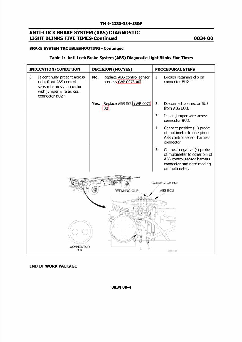
3. Is continuity present acrossright front ABS controlsensor harness connectorwith jumper wire acrossconnector BU2?
No. Replace ABS control sensorharness (WP 0073 00).
1. Loosen retaining clip onconnector BU2.
Yes. Replace ABS ECU (WP 007100).
2. Disconnect connector BU2from ABS ECU.
3. Install jumper wire across
connector BU2.
4. Connect positive (+) probeof multimeter to one pin of ABS control sensor harnessconnector.
5. Connect negative (-) probeof multimeter to other pin of ABS control sensor harnessconnector and note readingon multimeter.
END OF WORK PACKAGE

8/14/2019 TM 9-2330-334-13P M1147 FMTV-LHST TRAILER PART 2
http://slidepdf.com/reader/full/tm-9-2330-334-13p-m1147-fmtv-lhst-trailer-part-2 39/147
TM 9-2330-334-13&P
ANTI-LOCK BRAKE SYSTEM (ABS) DIAGNOSTICLIGHT BLINKS SIX TIMES 0035 00
THIS WORK PACKAGE COVERS:Brake System Troubleshooting
0035 00-1
INITIAL SETUP:
Maintenance LevelField
Tools/Special Tools Tool Kit, Genl Mech (Item 22, WP 0167 00)
Materials/PartsTies, Cable, Plastic (Item 20, WP 0165 00)
Personnel Required Two
Equipment ConditionsTrailer coupled (TM 9-2320-392-10-1).
PROCEDURE
WARNING
Remove rings, bracelets, watches, necklaces, and any other jewelry before workingaround vehicle. Jewelry can catch on equipment and cause injury or short acrosselectrical circuit and cause severe burns or electrical shock. Failure to comply mayresult in injury to personnel.
CAUTION
Use care when testing electrical connectors. Do not damage connector pins or sockets withmultimeter probes. Failure to comply may result in damage to equipment.
Do not pry or push ABS wheel speed sensor with sharp objects. Failure to comply may resultin damage to equipment.
NOTEReturn vehicle to mission capable condition and perform (Operational Checkout andTroubleshooting Procedures WP 0013 00) after a corrective action has been performed.

8/14/2019 TM 9-2330-334-13P M1147 FMTV-LHST TRAILER PART 2
http://slidepdf.com/reader/full/tm-9-2330-334-13p-m1147-fmtv-lhst-trailer-part-2 40/147

8/14/2019 TM 9-2330-334-13P M1147 FMTV-LHST TRAILER PART 2
http://slidepdf.com/reader/full/tm-9-2330-334-13p-m1147-fmtv-lhst-trailer-part-2 41/147
TM 9-2330-334-13&P
ANTI-LOCK BRAKE SYSTEM (ABS) DIAGNOSTICLIGHT BLINKS SIX TIMES-Continued 0035 00
BRAKE SYSTEM TROUBLESHOOTING - Continued
Table 1: Anti-Lock Brake System (ABS) Diagnostic Light Blinks Six Times
0035 00-3
INDICATION/CONDITION DECISION (NO/YES) PROCEDURAL STEPS
2. Is 700-3000 ohms of resistance is present acrossleft front ABS wheel speedsensor.
No. Replace left front ABSwheel speed sensor (WP0070 00).
1. Set multimeter to ohms.
Yes. Go to (Indication/Condition3).
2. Disconnect left front ABSwheel speed sensor harnessconnector from ABS wheelspeed sensor.
3. Connect positive (+) probeof multimeter to one socketof ABS wheel speed sensorconnector.
4. Connect negative (-) probeof multimeter to othersocket of ABS wheel speedsensor connector and notereading on multimeter.

8/14/2019 TM 9-2330-334-13P M1147 FMTV-LHST TRAILER PART 2
http://slidepdf.com/reader/full/tm-9-2330-334-13p-m1147-fmtv-lhst-trailer-part-2 42/147
TM 9-2330-334-13&P
ANTI-LOCK BRAKE SYSTEM (ABS) DIAGNOSTICLIGHT BLINKS SIX TIMES-Continued 0035 00
BRAKE SYSTEM TROUBLESHOOTING - Continued
Table 1: Anti-Lock Brake System (ABS) Diagnostic Light Blinks Six Times
0035 00-4
INDICATION/CONDITION DECISION (NO/YES) PROCEDURAL STEPS
3. Is continuity present acrossleft front ABS control sensorharness connector with jumper wire acrossconnector YE2?
No. Replace ABS control sensorharness (WP 0073 00).
1. Loosen retaining clip onconnector YE2.
Yes. Replace ABS ECU (WP 007100).
2. Disconnect connector YE2from ABS ECU.
3. Install jumper wire across
connector YE2.
4. Connect positive (+) probeof multimeter to one pin of ABS control sensor harnessconnector.
5. Connect negative (-) probeof multimeter to other pin of ABS control sensor harnessconnector and note readingon multimeter.
END OF WORK PACKAGE

8/14/2019 TM 9-2330-334-13P M1147 FMTV-LHST TRAILER PART 2
http://slidepdf.com/reader/full/tm-9-2330-334-13p-m1147-fmtv-lhst-trailer-part-2 43/147
TM 9-2330-334-13&P
ANTI-LOCK BRAKE SYSTEM (ABS) DIAGNOSTICLIGHT BLINKS SEVEN TIMES 0036 00
THIS WORK PACKAGE COVERS:Brake System Troubleshooting
0036 00-1
INITIAL SETUP:
Maintenance LevelField
Tools/Special Tools Tool Kit, Genl Mech (Item 22, WP 0167 00)
Materials/PartsCable Ties, Plastic (Item 20, WP 0165 00) Wire, Elect, 50 ft (Item 22, WP 0165 00)
Personnel Required Two
Equipment ConditionsTrailer coupled (TM 9-2320-392-10-1).
PROCEDURE
WARNING
Remove rings, bracelets, watches, necklaces, and any other jewelry before workingaround vehicle. Jewelry can catch on equipment and cause injury or short acrosselectrical circuit and cause severe burns or electrical shock. Failure to comply mayresult in injury to personnel.
CAUTION
Use care when testing electrical connectors. Do not damage connector pins or sockets withmultimeter probes. Failure to comply may result in damage to equipment.
NOTEReturn vehicle to mission capable condition and perform (Operational Checkout andTroubleshooting Procedures WP 0013 00) after a corrective action has been performed.

8/14/2019 TM 9-2330-334-13P M1147 FMTV-LHST TRAILER PART 2
http://slidepdf.com/reader/full/tm-9-2330-334-13p-m1147-fmtv-lhst-trailer-part-2 44/147

8/14/2019 TM 9-2330-334-13P M1147 FMTV-LHST TRAILER PART 2
http://slidepdf.com/reader/full/tm-9-2330-334-13p-m1147-fmtv-lhst-trailer-part-2 45/147

8/14/2019 TM 9-2330-334-13P M1147 FMTV-LHST TRAILER PART 2
http://slidepdf.com/reader/full/tm-9-2330-334-13p-m1147-fmtv-lhst-trailer-part-2 46/147
TM 9-2330-334-13&P
ANTI-LOCK BRAKE SYSTEM (ABS) DIAGNOSTICLIGHT BLINKS SEVEN TIMES-Continued 0036 00
BRAKE SYSTEM TROUBLESHOOTING - Continued
Table 1: Anti-Lock Brake System (ABS) Diagnostic Light Blinks Seven Times
0036 00-4
INDICATION/CONDITION DECISION (NO/YES) PROCEDURAL STEPS
3. Is continuity present from ABS ECU cable connector pin5 to ABS relay valveconnector pin 2?
No. Replace ABS relay valveharness (WP 0072 00).
1. Disconnect ABS relayharness connector from ABSrelay valve.
Yes. Go to (Indication/Condition4).
2. Connect positive (+) probeof multimeter to ABS relayharness connector pin 2.
3. Connect negative (-) probe
of multimeter to ABS ECUconnector pin 5 and notereading on multimeter.

8/14/2019 TM 9-2330-334-13P M1147 FMTV-LHST TRAILER PART 2
http://slidepdf.com/reader/full/tm-9-2330-334-13p-m1147-fmtv-lhst-trailer-part-2 47/147
TM 9-2330-334-13&P
ANTI-LOCK BRAKE SYSTEM (ABS) DIAGNOSTICLIGHT BLINKS SEVEN TIMES-Continued 0036 00
BRAKE SYSTEM TROUBLESHOOTING - Continued
Table 1: Anti-Lock Brake System (ABS) Diagnostic Light Blinks Seven Times
0036 00-5/6-Blank
INDICATION/CONDITION DECISION (NO/YES) PROCEDURAL STEPS
4. Is continuity present from ABS ECU cable connector pin6 to ABS relay valveconnector pin 4?
No. Replace ABS relay valveharness (WP 0072 00).
1. Connect positive (+) probeof multimeter to ABS relayharness connector pin 4.
Yes. Go to (Indication/Condition5).
2. Connect negative (-) probeof multimeter to ABS ECUconnector pin 6 and notereading on multimeter.
5. Is continuity present from ABS ECU cable connector pin7 to ABS relay valveconnector pin 3?
No. Replace ABS relay valveharness (WP 0072 00).
1. Connect positive (+) probeof multimeter to ABS relayharness connector pin 3.
Yes. Replace ABS ECU (WP 007100).
2. Connect negative (-) probeof multimeter to ABS ECUconnector pin 7 and notereading on multimeter.
END OF WORK PACKAGE

8/14/2019 TM 9-2330-334-13P M1147 FMTV-LHST TRAILER PART 2
http://slidepdf.com/reader/full/tm-9-2330-334-13p-m1147-fmtv-lhst-trailer-part-2 48/147

8/14/2019 TM 9-2330-334-13P M1147 FMTV-LHST TRAILER PART 2
http://slidepdf.com/reader/full/tm-9-2330-334-13p-m1147-fmtv-lhst-trailer-part-2 49/147

8/14/2019 TM 9-2330-334-13P M1147 FMTV-LHST TRAILER PART 2
http://slidepdf.com/reader/full/tm-9-2330-334-13p-m1147-fmtv-lhst-trailer-part-2 50/147
TM 9-2330-334-13&P
ANTI-LOCK BRAKE SYSTEM (ABS) DIAGNOSTICLIGHT BLINKS NINE TIMES-Continued 0037 00
BRAKE SYSTEM TROUBLESHOOTING - Continued
Table 1: Anti-Lock Brake System (ABS) Diagnostic Light Blinks Nine Times
0037 00-2
INDICATION/CONDITION DECISION (NO/YES) PROCEDURAL STEPS
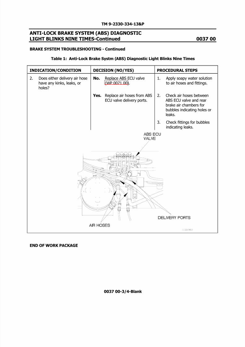
1. Is air present at two deliveryports on ABS ECU valve?
No. Replace ABS ECU valve(WP 0071 00).
1. Loosen air hoses of twodelivery ports of ABS ECU.
Yes. Go to (Indication/Condition2).
2. Start towing vehicle engine.
3. Depress brakes.
4. Check for presence of air attwo delivery ports of ABS
ECU valve.5. Shut off towing vehicle
engine.
6. Tighten hoses to ABS ECUdelivery ports.
8/14/2019 TM 9-2330-334-13P M1147 FMTV-LHST TRAILER PART 2
http://slidepdf.com/reader/full/tm-9-2330-334-13p-m1147-fmtv-lhst-trailer-part-2 51/147

8/14/2019 TM 9-2330-334-13P M1147 FMTV-LHST TRAILER PART 2
http://slidepdf.com/reader/full/tm-9-2330-334-13p-m1147-fmtv-lhst-trailer-part-2 52/147

8/14/2019 TM 9-2330-334-13P M1147 FMTV-LHST TRAILER PART 2
http://slidepdf.com/reader/full/tm-9-2330-334-13p-m1147-fmtv-lhst-trailer-part-2 53/147
TM 9-2330-334-13&P
ANTI-LOCK BRAKE SYSTEM (ABS) DIAGNOSTICLIGHT BLINKS TEN TIMES 0038 00
THIS WORK PACKAGE COVERS:Brake System Troubleshooting
0038 00-1
INITIAL SETUP:
Maintenance LevelField
Tools/Special Tools Tool Kit, Genl Mech (Item 22, WP 0167 00)
Materials/PartsCable Ties, Plastic (Item 20, WP 0165 00)
Personnel Required Two
Equipment ConditionsTrailer coupled (TM 9-2320-392-10-1).
PROCEDURE
WARNING
Remove rings, bracelets, watches, necklaces, and any other jewelry before workingaround vehicle. Jewelry can catch on equipment and cause injury or short acrosselectrical circuit and cause severe burns or electrical shock. Failure to comply mayresult in injury to personnel.
Wear appropriate eye protection when working under trailer due to possibility of falling debris and to protect from release of high pressure air. Failure to comply
may result in injury to personnel.
NOTEReturn vehicle to mission capable condition and perform (Operational Checkout andTroubleshooting Procedures WP 0013 00) after a corrective action has been performed.
Remove plastic cable ties as required.

8/14/2019 TM 9-2330-334-13P M1147 FMTV-LHST TRAILER PART 2
http://slidepdf.com/reader/full/tm-9-2330-334-13p-m1147-fmtv-lhst-trailer-part-2 54/147
TM 9-2330-334-13&P
ANTI-LOCK BRAKE SYSTEM (ABS) DIAGNOSTICLIGHT BLINKS TEN TIMES 0038 00
THIS WORK PACKAGE COVERS:Brake System Troubleshooting
Table 1: Anti-Lock Brake System (ABS) Diagnostic Light Blinks Ten Times
0038 00-2
INDICATION/CONDITION DECISION (NO/YES) PROCEDURAL STEPS
1. Is air present at supply portof ABS ECU valve?
No. Replace ABS ECU valve(WP 0071 00).
1. Loosen air hose of supplyport of ABS ECU.
Yes. Go to (Indication/Condition2).
2. Start towing vehicle engine.
3. Depress brakes.
4. Release brakes.
5. Check for presence of air atexhaust port of ABS ECUvalve.
6. Shut off towing vehicleengine.

8/14/2019 TM 9-2330-334-13P M1147 FMTV-LHST TRAILER PART 2
http://slidepdf.com/reader/full/tm-9-2330-334-13p-m1147-fmtv-lhst-trailer-part-2 55/147
TM 9-2330-334-13&P
ANTI-LOCK BRAKE SYSTEM (ABS) DIAGNOSTICLIGHT BLINKS TEN TIMES 0038 00
THIS WORK PACKAGE COVERS:Brake System Troubleshooting
Table 1: Anti-Lock Brake System (ABS) Diagnostic Light Blinks Ten Times
0038 00-3/4-Blank
INDICATION/CONDITION DECISION (NO/YES) PROCEDURAL STEPS
2. Does supply air hose 301have any kinks, leaks, orholes?
No. Replace ABS ECU valve(WP 0071 00).
1. Apply soapy water solutionto air hose 301 and fittingsof supply port.
Yes. Replace air hose 301. 2. Check air hoses between ABS ECU valve and air tank for bubbles indicating holesor leaks.
3. Check fittings for bubblesindicating leaks.
END OF WORK PACKAGE

8/14/2019 TM 9-2330-334-13P M1147 FMTV-LHST TRAILER PART 2
http://slidepdf.com/reader/full/tm-9-2330-334-13p-m1147-fmtv-lhst-trailer-part-2 56/147

8/14/2019 TM 9-2330-334-13P M1147 FMTV-LHST TRAILER PART 2
http://slidepdf.com/reader/full/tm-9-2330-334-13p-m1147-fmtv-lhst-trailer-part-2 57/147
TM 9-2330-334-13&P
ANTI-LOCK BRAKE SYSTEM (ABS) DIAGNOSTICLIGHT BLINKS ELEVEN TIMES 0039 00
THIS WORK PACKAGE COVERS:Brake System Troubleshooting
0039 00-1
INITIAL SETUP:
Maintenance LevelField
Tools/Special Tools Tool Kit, Genl Mech (Item 22, WP 0167 00)
Materials/PartsCable Ties, Plastic (Item 20, WP 0165 00) Soap, Laundry (Item 16, WP 0165 00)
Personnel Required Two
Equipment ConditionsTrailer coupled (TM 9-2320-392-10-1).
PROCEDURE
WARNING
Remove rings, bracelets, watches, necklaces, and any other jewelry before workingaround vehicle. Jewelry can catch on equipment and cause injury or short acrosselectrical circuit and cause severe burns or electrical shock. Failure to comply mayresult in injury to personnel.
Wear appropriate eye protection when working under trailer due to possibility of
falling debris and to protect from release of high pressure air. Failure to complymay result in injury to personnel.
NOTEReturn vehicle to mission capable condition and perform (Operational Checkout andTroubleshooting Procedures WP 0013 00) after a corrective action has been performed.
Remove plastic cable ties as required.

8/14/2019 TM 9-2330-334-13P M1147 FMTV-LHST TRAILER PART 2
http://slidepdf.com/reader/full/tm-9-2330-334-13p-m1147-fmtv-lhst-trailer-part-2 58/147
TM 9-2330-334-13&P
ANTI-LOCK BRAKE SYSTEM (ABS) DIAGNOSTICLIGHT BLINKS ELEVEN TIMES 0039 00
THIS WORK PACKAGE COVERS:Brake System Troubleshooting
Table 1: Anti-Lock Brake System (ABS) Diagnostic Light Blinks Eleven Times
0039 00-2
INDICATION/CONDITION DECISION (NO/YES) PROCEDURAL STEPS
1. Is air present at control porton ABS ECU valve?
No. Go to (Indication/Condition2).
1. Start towing vehicle engine.
Yes. Replace ABS ECU valve(WP 0071 00).
2. Loosen connection of airhose 105 at control port of ABS ECU.
3. Depress brakes.
4. Check for presence of air atcontrol port of ABS ECUvalve.
5. Release brakes.
6. Shut off towing vehicleengine.
7. Tighten air hose 105 to ABSECU valve control port.

8/14/2019 TM 9-2330-334-13P M1147 FMTV-LHST TRAILER PART 2
http://slidepdf.com/reader/full/tm-9-2330-334-13p-m1147-fmtv-lhst-trailer-part-2 59/147
TM 9-2330-334-13&P
ANTI-LOCK BRAKE SYSTEM (ABS) DIAGNOSTICLIGHT BLINKS ELEVEN TIMES 0039 00
THIS WORK PACKAGE COVERS:Brake System Troubleshooting
Table 1: Anti-Lock Brake System (ABS) Diagnostic Light Blinks Eleven Times
0039 00-3/4-Blank
INDICATION/CONDITION DECISION (NO/YES) PROCEDURAL STEPS
2. Does air hose 105 have anykinks, leaks or holes?
No. Go to Air System LosesPressure DuringOperation/Slow AirPressure Buildup (WP 004200).
1. Apply soapy water solutionto air hose 105 and fittingsof control port.
Yes. Replace air hose 105. 2. Start towing vehicle engine.
3. Depress brakes.
4. Check air hose 105 between ABS ECU and rear four porttask valve for bubblesindicating holes or leaks.
END OF WORK PACKAGE

8/14/2019 TM 9-2330-334-13P M1147 FMTV-LHST TRAILER PART 2
http://slidepdf.com/reader/full/tm-9-2330-334-13p-m1147-fmtv-lhst-trailer-part-2 60/147

8/14/2019 TM 9-2330-334-13P M1147 FMTV-LHST TRAILER PART 2
http://slidepdf.com/reader/full/tm-9-2330-334-13p-m1147-fmtv-lhst-trailer-part-2 61/147
TM 9-2330-334-13&P
ANTI-LOCK BRAKE SYSTEM (ABS) DIAGNOSTICLIGHT BLINKS FOURTEEN TIMES 0040 00
THIS WORK PACKAGE COVERS:Brake System Troubleshooting
0040 00-1
INITIAL SETUP:
Maintenance LevelField
Tools/Special Tools Tool Kit, Genl Mech (Item 22, WP 0167 00)
Materials/PartsCable Ties, Plastic (Item 20, WP 0165 00)
Personnel Required Two
Equipment ConditionsTrailer coupled (TM 9-2320-392-10-1).
PROCEDURE
WARNING
Remove rings, bracelets, watches, necklaces, and any other jewelry before workingaround vehicle. Jewelry can catch on equipment and cause injury or short acrosselectrical circuit and cause severe burns or electrical shock. Failure to comply mayresult in injury to personnel.
CAUTION
Use care when testing electrical connectors. Do not damage connector pins or sockets withmultimeter probes. Failure to comply may result in damage to equipment.
NOTEReturn vehicle to mission capable condition and perform (Operational Checkout andTroubleshooting Procedures WP 0013 00) after a corrective action has been performed.

8/14/2019 TM 9-2330-334-13P M1147 FMTV-LHST TRAILER PART 2
http://slidepdf.com/reader/full/tm-9-2330-334-13p-m1147-fmtv-lhst-trailer-part-2 62/147
TM 9-2330-334-13&P
ANTI-LOCK BRAKE SYSTEM (ABS) DIAGNOSTICLIGHT BLINKS FOURTEEN TIMES-Continued 0040 00
BRAKE SYSTEM TROUBLESHOOTING - Continued
Table 1: Anti-Lock Brake System (ABS) Diagnostic Light Blinks Fourteen Times
0040 00-2
INDICATION/CONDITION DECISION (NO/YES) PROCEDURAL STEPS
1. Is 8-14 VDC present at ABSECU power/diagnosticconnector pin 3?
No. Go to (Indication/Condition3).
1. Set multimeter to VDC.
Yes. Go to (Indication/Condition2).
2. Disconnect ABS ECUpower/diagnostic cableconnector from ABS ECU.
3. Connect positive (+) probeof multimeter to ABS ECU
power/diagnostic cableconnector pin 3.
4. Connect negative (-) probeof multimeter to a knowngood ground.
5. Start engine on towingvehicle and note reading onmultimeter.

8/14/2019 TM 9-2330-334-13P M1147 FMTV-LHST TRAILER PART 2
http://slidepdf.com/reader/full/tm-9-2330-334-13p-m1147-fmtv-lhst-trailer-part-2 63/147
TM 9-2330-334-13&P
ANTI-LOCK BRAKE SYSTEM (ABS) DIAGNOSTICLIGHT BLINKS FOURTEEN TIMES-Continued 0040 00
BRAKE SYSTEM TROUBLESHOOTING - Continued
Table 1: Anti-Lock Brake System (ABS) Diagnostic Light Blinks Fourteen Times
0040 00-3
INDICATION/CONDITION DECISION (NO/YES) PROCEDURAL STEPS
2. Is continuity present from ABS ECU Power/Diagnosticcable connector pin 4 to aknown good ground?
No. Go to (Indication/Condition7).
1. Set multimeter to ohms.
Yes. Replace ABS ECU (WP 007100).
2. Connect positive (+) probeof multimeter to ABS ECUPower/Diagnostic cableconnector pin 4.
3. Connect negative (-) probeof multimeter to a knowngood ground and notereading on multimeter.

8/14/2019 TM 9-2330-334-13P M1147 FMTV-LHST TRAILER PART 2
http://slidepdf.com/reader/full/tm-9-2330-334-13p-m1147-fmtv-lhst-trailer-part-2 64/147
TM 9-2330-334-13&P
ANTI-LOCK BRAKE SYSTEM (ABS) DIAGNOSTICLIGHT BLINKS FOURTEEN TIMES-Continued 0040 00
BRAKE SYSTEM TROUBLESHOOTING - Continued
Table 1: Anti-Lock Brake System (ABS) Diagnostic Light Blinks Fourteen Times
0040 00-4
INDICATION/CONDITION DECISION (NO/YES) PROCEDURAL STEPS
3. Is continuity present from ABS Power/Diagnostic cableconnector pin 3 to blue wireon terminal 5 of Junctionbox?
No. Replace ABS ECUPower/Diagnostic controlharness (WP 0074 00).
1. Set multimeter to ohms.
Yes. Go to (Indication/Condition4).
2. Remove cover from junctionbox (WP 0059 00).
3. Connect positive (+) probe
of multimeter to ABSPower/Diagnostic cableconnector pin 3.
4. Connect negative (-) probeof multimeter to blue wireon terminal 5 of Junctionbox and note reading onmultimeter.
8/14/2019 TM 9-2330-334-13P M1147 FMTV-LHST TRAILER PART 2
http://slidepdf.com/reader/full/tm-9-2330-334-13p-m1147-fmtv-lhst-trailer-part-2 65/147
TM 9-2330-334-13&P
ANTI-LOCK BRAKE SYSTEM (ABS) DIAGNOSTICLIGHT BLINKS FOURTEEN TIMES-Continued 0040 00
BRAKE SYSTEM TROUBLESHOOTING - Continued
Table 1: Anti-Lock Brake System (ABS) Diagnostic Light Blinks Fourteen Times
0040 00-5
INDICATION/CONDITION DECISION (NO/YES) PROCEDURAL STEPS
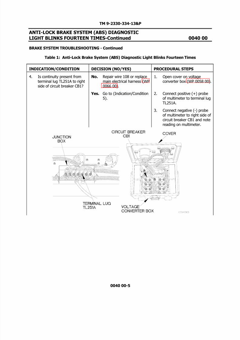
4. Is continuity present fromterminal lug TL251A to rightside of circuit breaker CB1?
No. Repair wire 108 or replacemain electrical harness (WP0066 00).
1. Open cover on voltageconverter box (WP 0058 00).
Yes. Go to (Indication/Condition5).
2. Connect positive (+) probeof multimeter to terminal lugTL251A.
3. Connect negative (-) probeof multimeter to right side of
circuit breaker CB1 and notereading on multimeter.
8/14/2019 TM 9-2330-334-13P M1147 FMTV-LHST TRAILER PART 2
http://slidepdf.com/reader/full/tm-9-2330-334-13p-m1147-fmtv-lhst-trailer-part-2 66/147
TM 9-2330-334-13&P
ANTI-LOCK BRAKE SYSTEM (ABS) DIAGNOSTICLIGHT BLINKS FOURTEEN TIMES-Continued 0040 00
BRAKE SYSTEM TROUBLESHOOTING - Continued
Table 1: Anti-Lock Brake System (ABS) Diagnostic Light Blinks Fourteen Times
0040 00-6
INDICATION/CONDITION DECISION (NO/YES) PROCEDURAL STEPS
5. Is 18-30 VDC present at 24 VDC Intervehicular cableconnector pin K?
No. Replace 24 VDCIntervehicular Cable (WP0062 00).
1. Set multimeter to VDC.
Yes. Go to (Indication/Condition6).
2. Disconnect intervehicularcable from voltage converterbox.
3. Connect positive (+) probeof multimeter to 24 VDC
Intervehicular cableconnector pin K.
4. Connect negative (-) probeof multimeter to a knowngood ground.
5. Start engine of towingvehicle and note reading onmultimeter.

8/14/2019 TM 9-2330-334-13P M1147 FMTV-LHST TRAILER PART 2
http://slidepdf.com/reader/full/tm-9-2330-334-13p-m1147-fmtv-lhst-trailer-part-2 67/147
TM 9-2330-334-13&P
ANTI-LOCK BRAKE SYSTEM (ABS) DIAGNOSTICLIGHT BLINKS FOURTEEN TIMES-Continued 0040 00
BRAKE SYSTEM TROUBLESHOOTING - Continued
Table 1: Anti-Lock Brake System (ABS) Diagnostic Light Blinks Fourteen Times
0040 00-7
INDICATION/CONDITION DECISION (NO/YES) PROCEDURAL STEPS
6. Is continuity present acrosscircuit breaker CB1?
No. Replace circuit breaker CB1(WP 0057 00).
1. Set multimeter to ohms.
Yes. Replace voltage converterbox (WP 0058 00).
2. Connect positive (+) probeof multimeter to oneterminal of circuit breakerCB1.
3. Connect negative (-) probeof multimeter to other
terminal of circuit breakerCB1 and note reading onmultimeter.

8/14/2019 TM 9-2330-334-13P M1147 FMTV-LHST TRAILER PART 2
http://slidepdf.com/reader/full/tm-9-2330-334-13p-m1147-fmtv-lhst-trailer-part-2 68/147

8/14/2019 TM 9-2330-334-13P M1147 FMTV-LHST TRAILER PART 2
http://slidepdf.com/reader/full/tm-9-2330-334-13p-m1147-fmtv-lhst-trailer-part-2 69/147
TM 9-2330-334-13&P
ANTI-LOCK BRAKE SYSTEM (ABS) DIAGNOSTICLIGHT BLINKS FOURTEEN TIMES-Continued 0040 00
BRAKE SYSTEM TROUBLESHOOTING - Continued
Table 1: Anti-Lock Brake System (ABS) Diagnostic Light Blinks Fourteen Times
0040 00-9/10-Blank
INDICATION/CONDITION DECISION (NO/YES) PROCEDURAL STEPS
8. Is continuity present fromterminal lug TL261A toterminal lug TL261?
No. Replace main electricalharness (WP 0066 00).
1. Open cover on voltageconverter box (WP 0058 00).
Yes. Replace voltage converterbox (WP 0058 00).
2. Connect positive (+) probeof multimeter to terminal lugTL261A.
3. Connect negative (-) probeof multimeter to terminal lug
TL261 and note reading onmultimeter.
END OF WORK PACKAGE

8/14/2019 TM 9-2330-334-13P M1147 FMTV-LHST TRAILER PART 2
http://slidepdf.com/reader/full/tm-9-2330-334-13p-m1147-fmtv-lhst-trailer-part-2 70/147
8/14/2019 TM 9-2330-334-13P M1147 FMTV-LHST TRAILER PART 2
http://slidepdf.com/reader/full/tm-9-2330-334-13p-m1147-fmtv-lhst-trailer-part-2 71/147
TM 9-2330-334-13&P
ANTI-LOCK BRAKE SYSTEM (ABS) DIAGNOSTICLIGHT BLINKS FIFTEEN TIMES 0041 00
THIS WORK PACKAGE COVERS:Brakes System Troubleshooting
0041 00-1
INITIAL SETUP:
Maintenance LevelField
Tools/Special Tools Tool Kit, Genl Mech (Item 22, WP 0167 00)
Personnel Required Two
Equipment ConditionsTrailer coupled (TM 9-2320-392-10-1).
PROCEDURE
WARNING
Remove rings, bracelets, watches, necklaces, and any other jewelry before workingaround vehicle. Jewelry can catch on equipment and cause injury or short acrosselectrical circuit and cause severe burns or electrical shock. Failure to comply mayresult in injury to personnel.
CAUTION
Use care when testing electrical connectors. Do not damage connector pins or sockets with
multimeter probes. Failure to comply may result in damage to equipment.
NOTEReturn vehicle to mission capable condition and perform (Operational Checkout andTroubleshooting Procedures WP 0013 00) after a corrective action has been performed.
8/14/2019 TM 9-2330-334-13P M1147 FMTV-LHST TRAILER PART 2
http://slidepdf.com/reader/full/tm-9-2330-334-13p-m1147-fmtv-lhst-trailer-part-2 72/147
TM 9-2330-334-13&P
ANTI-LOCK BRAKE SYSTEM (ABS) DIAGNOSTICLIGHT BLINKS FIFTEEN TIMES-Continued 0041 00
BRAKES SYSTEM TROUBLESHOOTING - Continued
Table 1: Anti-Lock Brake System (ABS) Diagnostic Light Blinks Fifteen Times
0041 00-2
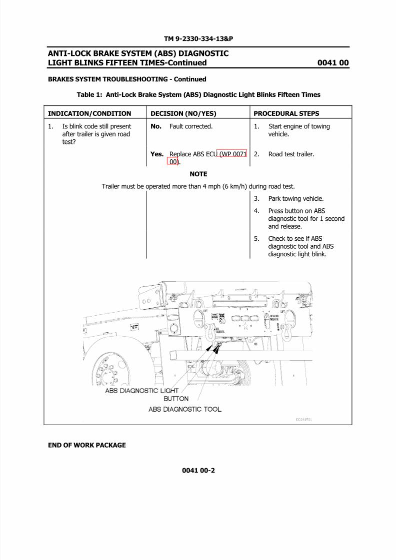
INDICATION/CONDITION DECISION (NO/YES) PROCEDURAL STEPS
1. Is blink code still presentafter trailer is given roadtest?
No. Fault corrected. 1. Start engine of towingvehicle.
Yes. Replace ABS ECU (WP 007100).
2. Road test trailer.
NOTE
Trailer must be operated more than 4 mph (6 km/h) during road test.
3. Park towing vehicle.
4. Press button on ABSdiagnostic tool for 1 secondand release.
5. Check to see if ABSdiagnostic tool and ABSdiagnostic light blink.
END OF WORK PACKAGE

8/14/2019 TM 9-2330-334-13P M1147 FMTV-LHST TRAILER PART 2
http://slidepdf.com/reader/full/tm-9-2330-334-13p-m1147-fmtv-lhst-trailer-part-2 73/147
TM 9-2330-334-13&P
AIR SYSTEM LOSES PRESSURE DURINGOPERATION/SLOW AIR PRESSURE BUILDUP 0042 00
THIS WORK PACKAGE COVERS: Air System Troubleshooting
0042 00-1
INITIAL SETUP:
Maintenance LevelField
Tools/Special Tools Tool Kit, Genl Mech (Item 22, WP 0167 00)
Materials/PartsTies, Cable, Plastic (Item 20, WP 0165 00) Soap, Laundry (Item 16, WP 0165 00)
Personnel Required Two
ReferencesTowing vehicle operators manual
Equipment Conditions Air system charged (TM 9-2320-392-10-1)
PROCEDURE
WARNING
Remove rings, bracelets, watches, necklaces, and any other jewelry before workingaround vehicle. Jewelry can catch on equipment and cause injury or short acrosselectrical circuit and cause severe burns or electrical shock. Failure to comply mayresult in injury to personnel.
Wear appropriate eye protection when working under trailer due to possibility of falling debris and to protect from release of high pressure air. Failure to comply
may result in injury to personnel.
NOTEReturn vehicle to mission capable condition and perform (Operational Checkout andTroubleshooting Procedures WP 0013 00) after a corrective action has been performed.
Tag hoses and connection points prior to disconnecting.
Remove plastic cable ties as required.
Reference pneumatic schematic at end of chapter as required.

8/14/2019 TM 9-2330-334-13P M1147 FMTV-LHST TRAILER PART 2
http://slidepdf.com/reader/full/tm-9-2330-334-13p-m1147-fmtv-lhst-trailer-part-2 74/147
TM 9-2330-334-13&P
AIR SYSTEM LOSES PRESSURE DURINGOPERATION/SLOW AIR PRESSURE BUILDUP 0042 00
AIR SYSTEM TROUBLESHOOTING - Continued
Table 1: Air System Loses Pressure During Operation/Slow Air Pressure Buildup
0042 00-2
INDICATION/CONDITION DECISION (NO/YES) PROCEDURAL STEPS
1. Is air tank drain valve openor leaking?
No Go to (Indication/Condition2).
1. Ensure air tank drain valve isclosed.
Yes Replace air tank drain valve(WP 0078 00).
2. Feel for air escaping from airtank drain valve.

8/14/2019 TM 9-2330-334-13P M1147 FMTV-LHST TRAILER PART 2
http://slidepdf.com/reader/full/tm-9-2330-334-13p-m1147-fmtv-lhst-trailer-part-2 75/147
TM 9-2330-334-13&P
AIR SYSTEM LOSES PRESSURE DURINGOPERATION/SLOW AIR PRESSURE BUILDUP 0042 00
AIR SYSTEM TROUBLESHOOTING - Continued
Table 1: Air System Loses Pressure During Operation/Slow Air Pressure Buildup
0042 00-3
INDICATION/CONDITION DECISION (NO/YES) PROCEDURAL STEPS
2. Are coupler seals ongladhands damaged ormissing?
No Go to (Indication/Condition3).
1. Check for missing ordamaged coupler seal onboth service and emergencygladhands.
Yes Replace gladhand couplerseal (WP 0079 00).
3. Do trailer service brakesoperate properly?
No Proceed to Service BrakesDo Not Apply (WP 004300).
1. Start towing vehicle engine.
Yes Go to (Indication/Condition4).
2. Depress brake pedal.
3. Check to see if trailer brakesoperate.
4. Shut off towing vehicleengine.

8/14/2019 TM 9-2330-334-13P M1147 FMTV-LHST TRAILER PART 2
http://slidepdf.com/reader/full/tm-9-2330-334-13p-m1147-fmtv-lhst-trailer-part-2 76/147
TM 9-2330-334-13&P
AIR SYSTEM LOSES PRESSURE DURINGOPERATION/SLOW AIR PRESSURE BUILDUP 0042 00
AIR SYSTEM TROUBLESHOOTING - Continued
Table 1: Air System Loses Pressure During Operation/Slow Air Pressure Buildup
0042 00-4
INDICATION/CONDITION DECISION (NO/YES) PROCEDURAL STEPS
4. Is air present at supply portof front four port task valve?
No Replace air hose 202. 1. Loosen air hoses at frontfour port task valve supplyport.
Yes Go to (Indication/Condition5).
2. Start towing vehicle engine.
3. Depress towing vehiclebrake pedal.
4. Check for presence of air.5. Shut down towing vehicle
engine.
6. Tighten air hoses to fourport task valve supply port.

8/14/2019 TM 9-2330-334-13P M1147 FMTV-LHST TRAILER PART 2
http://slidepdf.com/reader/full/tm-9-2330-334-13p-m1147-fmtv-lhst-trailer-part-2 77/147
TM 9-2330-334-13&P
AIR SYSTEM LOSES PRESSURE DURINGOPERATION/SLOW AIR PRESSURE BUILDUP 0042 00
AIR SYSTEM TROUBLESHOOTING - Continued
Table 1: Air System Loses Pressure During Operation/Slow Air Pressure Buildup
0042 00-5
INDICATION/CONDITION DECISION (NO/YES) PROCEDURAL STEPS
5. Is air present at deliveryports of front four port task valve?
No Replace front four port task valve (WP 0109 00).
1. Loosen air hoses at frontfour port task valve deliveryport.
Yes Go to (Indication/Condition6).
2. Start towing vehicle engine.
3. Depress towing vehiclebrake pedal.
4. Check for presence of air.5. Shut down towing vehicle
engine.
6. Tighten air hoses to frontfour port task valve supplyport.
8/14/2019 TM 9-2330-334-13P M1147 FMTV-LHST TRAILER PART 2
http://slidepdf.com/reader/full/tm-9-2330-334-13p-m1147-fmtv-lhst-trailer-part-2 78/147
TM 9-2330-334-13&P
AIR SYSTEM LOSES PRESSURE DURINGOPERATION/SLOW AIR PRESSURE BUILDUP 0042 00
AIR SYSTEM TROUBLESHOOTING - Continued
Table 1: Air System Loses Pressure During Operation/Slow Air Pressure Buildup
0042 00-6
INDICATION/CONDITION DECISION (NO/YES) PROCEDURAL STEPS
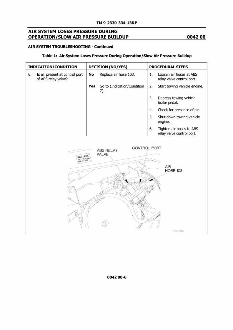
6. Is air present at control portof ABS relay valve?
No Replace air hose 103. 1. Loosen air hoses at ABSrelay valve control port.
Yes Go to (Indication/Condition7).
2. Start towing vehicle engine.
3. Depress towing vehiclebrake pedal.
4. Check for presence of air.
5. Shut down towing vehicleengine.
6. Tighten air hoses to ABSrelay valve control port.

8/14/2019 TM 9-2330-334-13P M1147 FMTV-LHST TRAILER PART 2
http://slidepdf.com/reader/full/tm-9-2330-334-13p-m1147-fmtv-lhst-trailer-part-2 79/147
TM 9-2330-334-13&P
AIR SYSTEM LOSES PRESSURE DURINGOPERATION/SLOW AIR PRESSURE BUILDUP 0042 00
AIR SYSTEM TROUBLESHOOTING - Continued
Table 1: Air System Loses Pressure During Operation/Slow Air Pressure Buildup
0042 00-7
INDICATION/CONDITION DECISION (NO/YES) PROCEDURAL STEPS
7. Is air present at supply portof rear four port task valve?
No Replace air hose 201. 1. Loosen air hoses at rear fourport task valve supply port.
Yes Go to (Indication/Condition8).
2. Start towing vehicle engine.
3. Depress towing vehiclebrake pedal.
4. Check for presence of air.
5. Shut down towing vehicleengine.
6. Tighten air hoses to rearfour port valve supply port.

8/14/2019 TM 9-2330-334-13P M1147 FMTV-LHST TRAILER PART 2
http://slidepdf.com/reader/full/tm-9-2330-334-13p-m1147-fmtv-lhst-trailer-part-2 80/147
TM 9-2330-334-13&P
AIR SYSTEM LOSES PRESSURE DURINGOPERATION/SLOW AIR PRESSURE BUILDUP 0042 00
AIR SYSTEM TROUBLESHOOTING - Continued
Table 1: Air System Loses Pressure During Operation/Slow Air Pressure Buildup
0042 00-8
INDICATION/CONDITION DECISION (NO/YES) PROCEDURAL STEPS
8. Is air present at control portof ABS ECU?
No Go to (Indication/Condition9).
1. Loosen air hoses at ABS ECUvalve control port.
Yes Go to (Indication/Condition10).
2. Start towing vehicle engine.
3. Depress towing vehiclebrake pedal.
4. Check for presence of air.
5. Shut down towing vehicleengine.
6. Tighten air hoses to ABSECU valve control port.

8/14/2019 TM 9-2330-334-13P M1147 FMTV-LHST TRAILER PART 2
http://slidepdf.com/reader/full/tm-9-2330-334-13p-m1147-fmtv-lhst-trailer-part-2 81/147
TM 9-2330-334-13&P
AIR SYSTEM LOSES PRESSURE DURINGOPERATION/SLOW AIR PRESSURE BUILDUP 0042 00
AIR SYSTEM TROUBLESHOOTING - Continued
Table 1: Air System Loses Pressure During Operation/Slow Air Pressure Buildup
0042 00-9
INDICATION/CONDITION DECISION (NO/YES) PROCEDURAL STEPS
9. Does air hose 105 have anykinks, leaks or holes?
No Replace rear four port task valve (WP 0109 00).
1. Apply soapy water solutionto air hose 105 and fittings.
Yes Replace air hose 105. 2. Check air hose 105 between ABS ECU valve and four porttask valve for bubblesindicating holes or leaks.
3. Check fittings for bubblesindicating leaks.

8/14/2019 TM 9-2330-334-13P M1147 FMTV-LHST TRAILER PART 2
http://slidepdf.com/reader/full/tm-9-2330-334-13p-m1147-fmtv-lhst-trailer-part-2 82/147
TM 9-2330-334-13&P
AIR SYSTEM LOSES PRESSURE DURINGOPERATION/SLOW AIR PRESSURE BUILDUP 0042 00
AIR SYSTEM TROUBLESHOOTING - Continued
Table 1: Air System Loses Pressure During Operation/Slow Air Pressure Buildup
0042 00-10
INDICATION/CONDITION DECISION (NO/YES) PROCEDURAL STEPS
10. Is air present at supply portof ABS ECU valve?
No Go to (Indication/Condition11).
1. Loosen air hose at ABS ECUvalve supply port.
Yes Replace air tank (WP 007800).
2. Start towing vehicle engine.
3. Depress towing vehiclebrake pedal.
4. Check for presence of air.
5. Shut down towing vehicleengine.
6. Tighten air hose to ABS ECUvalve supply port.
8/14/2019 TM 9-2330-334-13P M1147 FMTV-LHST TRAILER PART 2
http://slidepdf.com/reader/full/tm-9-2330-334-13p-m1147-fmtv-lhst-trailer-part-2 83/147
TM 9-2330-334-13&P
AIR SYSTEM LOSES PRESSURE DURING
OPERATION/SLOW AIR PRESSURE BUILDUP 0042 00
AIR SYSTEM TROUBLESHOOTING - Continued
Table 1: Air System Loses Pressure During Operation/Slow Air Pressure Buildup
0042 00-11/12-Blank
INDICATION/CONDITION DECISION (NO/YES) PROCEDURAL STEPS
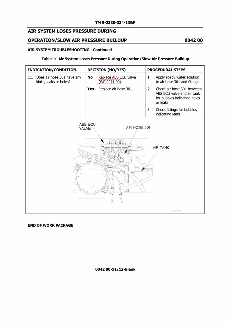
11. Does air hose 301 have anykinks, leaks or holes?
No Replace ABS ECU valve(WP 0071 00).
1. Apply soapy water solutionto air hose 301 and fittings.
Yes Replace air hose 301. 2. Check air hose 301 between ABS ECU valve and air tank for bubbles indicating holesor leaks.
3. Check fittings for bubbles
indicating leaks.
END OF WORK PACKAGE

8/14/2019 TM 9-2330-334-13P M1147 FMTV-LHST TRAILER PART 2
http://slidepdf.com/reader/full/tm-9-2330-334-13p-m1147-fmtv-lhst-trailer-part-2 84/147

8/14/2019 TM 9-2330-334-13P M1147 FMTV-LHST TRAILER PART 2
http://slidepdf.com/reader/full/tm-9-2330-334-13p-m1147-fmtv-lhst-trailer-part-2 85/147
TM 9-2330-334-13&P
SERVICE BRAKES DO NOT APPLY 0043 00
THIS WORK PACKAGE COVERS:Brakes Troubleshooting
0043 00-1
INITIAL SETUP:
Maintenance LevelField
Tools/Special Tools Tool Kit, Genl Mech (Item 22, WP 0167 00)
Materials/PartsTies, Cable, Plastic (Item 20, WP 0165 00) Soap, Laundry (Item 16, WP 0165 00)
Personnel Required Two
ReferencesTowing vehicle operators manual
Equipment Conditions Air system charged (TM 9-2320-392-10-1)
PROCEDURE
WARNING
Remove rings, bracelets, watches, necklaces, and any other jewelry before workingaround vehicle. Jewelry can catch on equipment and cause injury or short acrosselectrical circuit and cause severe burns or electrical shock. Failure to comply mayresult in injury to personnel.
Wear appropriate eye protection when working under trailer due to possibility of falling debris and to protect from release of high pressure air. Failure to complymay result in injury to personnel.
NOTEReturn vehicle to mission capable condition and perform (Operational Checkout andTroubleshooting Procedures WP 0013 00) after a corrective action has been performed.
Remove plastic cable ties as required.
Reference pneumatic schematic at end of chapter as required.

8/14/2019 TM 9-2330-334-13P M1147 FMTV-LHST TRAILER PART 2
http://slidepdf.com/reader/full/tm-9-2330-334-13p-m1147-fmtv-lhst-trailer-part-2 86/147
TM 9-2330-334-13&P
SERVICE BRAKES DO NOT APPLY-Continued 0043 00
BRAKES TROUBLESHOOTING - Continued
Table 1: Service Brakes Do Not Apply
0043 00-2
INDICATION/CONDITION DECISION (NO/YES) PROCEDURAL STEPS
1. Is air tank drain valve openor leaking?
No Go to (Indication/Condition2).
1. Ensure air tank drain valve isclosed.
Yes Replace air tank drain valve(WP 0078 00).
2. Feel for air escaping from airtank drain valve.
8/14/2019 TM 9-2330-334-13P M1147 FMTV-LHST TRAILER PART 2
http://slidepdf.com/reader/full/tm-9-2330-334-13p-m1147-fmtv-lhst-trailer-part-2 87/147
TM 9-2330-334-13&P
SERVICE BRAKES DO NOT APPLY-Continued 0043 00
BRAKES TROUBLESHOOTING - Continued
Table 1: Service Brakes Do Not Apply
0043 00-3
INDICATION/CONDITION DECISION (NO/YES) PROCEDURAL STEPS
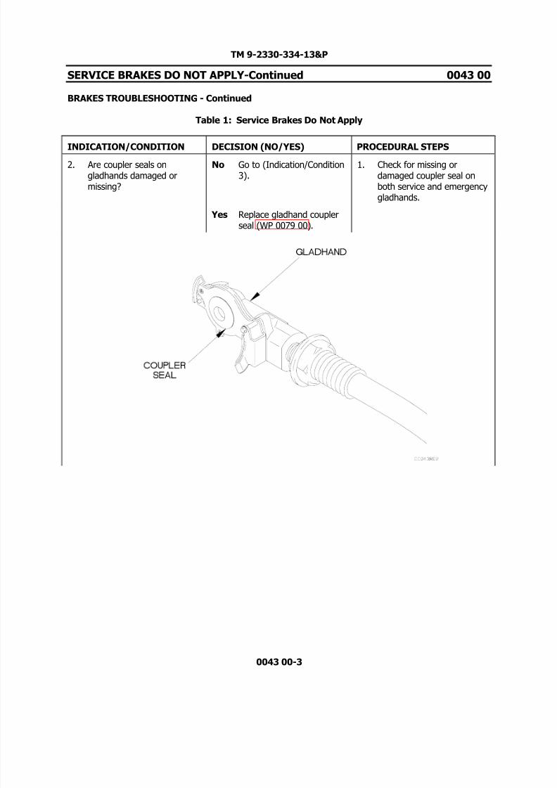
2. Are coupler seals ongladhands damaged ormissing?
No Go to (Indication/Condition3).
1. Check for missing ordamaged coupler seal onboth service and emergencygladhands.
Yes Replace gladhand couplerseal (WP 0079 00).

8/14/2019 TM 9-2330-334-13P M1147 FMTV-LHST TRAILER PART 2
http://slidepdf.com/reader/full/tm-9-2330-334-13p-m1147-fmtv-lhst-trailer-part-2 88/147
TM 9-2330-334-13&P
SERVICE BRAKES DO NOT APPLY-Continued 0043 00
BRAKES TROUBLESHOOTING - Continued
Table 1: Service Brakes Do Not Apply
0043 00-4
INDICATION/CONDITION DECISION (NO/YES) PROCEDURAL STEPS
3. Is air present at supply portof front four port task valve?
No Replace air hose 202. 1. Loosen air hose 202 fromsupply port on four port task valve.
Yes Go to (Indication/Condition4).
2. Start towing vehicle engine.
3. Depress towing vehiclebrake pedal.
4. Check for presence of air.
5. Shut down towing vehicleengine.
6. Tighten air hose202 to fourport task valve supply port.

8/14/2019 TM 9-2330-334-13P M1147 FMTV-LHST TRAILER PART 2
http://slidepdf.com/reader/full/tm-9-2330-334-13p-m1147-fmtv-lhst-trailer-part-2 89/147
TM 9-2330-334-13&P
SERVICE BRAKES DO NOT APPLY-Continued 0043 00
BRAKES TROUBLESHOOTING - Continued
Table 1: Service Brakes Do Not Apply
0043 00-5
INDICATION/CONDITION DECISION (NO/YES) PROCEDURAL STEPS
4. Is air present at deliveryports of front four port task valve?
No Replace front four port task valve (WP 0109 00).
1. Loosen air hoses at frontfour port task valve deliveryports.
Yes Go to (Indication/Condition5).
2. Start towing vehicle engine.
3. Depress towing vehiclebrake pedal.
4. Check for presence of air.
5. Shut down towing vehicleengine.
6. Tighten air hoses to fourport task valve deliveryports.

8/14/2019 TM 9-2330-334-13P M1147 FMTV-LHST TRAILER PART 2
http://slidepdf.com/reader/full/tm-9-2330-334-13p-m1147-fmtv-lhst-trailer-part-2 90/147
TM 9-2330-334-13&P
SERVICE BRAKES DO NOT APPLY-Continued 0043 00
BRAKES TROUBLESHOOTING - Continued
Table 1: Service Brakes Do Not Apply
0043 00-6
INDICATION/CONDITION DECISION (NO/YES) PROCEDURAL STEPS
5. Is air present at supply portof rear four port task valve?
No Replace air hose 201. 1. Loosen air hose 201 at rearfour port task valve supplyport.
Yes Go to (Indication/Condition6).
2. Start towing vehicle engine.
3. Depress towing vehiclebrake pedal.
4. Check for presence of air.
5. Shut down towing vehicleengine.
6. Tighten air hose 201 to rearfour port task valve supplyport.

8/14/2019 TM 9-2330-334-13P M1147 FMTV-LHST TRAILER PART 2
http://slidepdf.com/reader/full/tm-9-2330-334-13p-m1147-fmtv-lhst-trailer-part-2 91/147
TM 9-2330-334-13&P
SERVICE BRAKES DO NOT APPLY-Continued 0043 00
BRAKES TROUBLESHOOTING - Continued
Table 1: Service Brakes Do Not Apply
0043 00-7
INDICATION/CONDITION DECISION (NO/YES) PROCEDURAL STEPS
6. Is air present at control portof ABS ECU?
No Go to (Indication/Condition7).
1. Loosen air hose 105 at ABSECU valve control port.
Yes Go to (Indication/Condition8).
2. Start towing vehicle engine.
3. Depress towing vehiclebrake pedal.
4. Check for presence of air.
5. Shut down towing vehicle
engine.
6. Tighten air hose 105 to ABSECU valve control port.

8/14/2019 TM 9-2330-334-13P M1147 FMTV-LHST TRAILER PART 2
http://slidepdf.com/reader/full/tm-9-2330-334-13p-m1147-fmtv-lhst-trailer-part-2 92/147
TM 9-2330-334-13&P
SERVICE BRAKES DO NOT APPLY-Continued 0043 00
BRAKES TROUBLESHOOTING - Continued
Table 1: Service Brakes Do Not Apply
0043 00-8
INDICATION/CONDITION DECISION (NO/YES) PROCEDURAL STEPS
7. Does air hose 105 have anykinks, leaks, or holes?
No Replace rear four port task valve (WP 0109 00).
1. Apply soapy water solutionto air hose 105 and fittings.
Yes Replace air hose 105. 2. Check air hose 105 between ABS ECU valve and rear fourport task valve for bubblesindicating holes or leaks.
3. Check fittings for bubblesindicating leaks.

8/14/2019 TM 9-2330-334-13P M1147 FMTV-LHST TRAILER PART 2
http://slidepdf.com/reader/full/tm-9-2330-334-13p-m1147-fmtv-lhst-trailer-part-2 93/147

8/14/2019 TM 9-2330-334-13P M1147 FMTV-LHST TRAILER PART 2
http://slidepdf.com/reader/full/tm-9-2330-334-13p-m1147-fmtv-lhst-trailer-part-2 94/147
TM 9-2330-334-13&P
SERVICE BRAKES DO NOT APPLY-Continued 0043 00
BRAKES TROUBLESHOOTING - Continued
Table 1: Service Brakes Do Not Apply
0043 00-10
INDICATION/CONDITION DECISION (NO/YES) PROCEDURAL STEPS
9. Does air hose 301 have anykinks, leaks or holes?
No Replace rear four port task valve (WP 0109 00).
1. Apply soapy water solutionto air hose 301 and fittings.
Yes Replace air hose 301. 2. Check air hose 301 between ABS ECU valve and air tank for bubbles indicating holesor leaks.
3. Check fittings for bubblesindicating leaks.
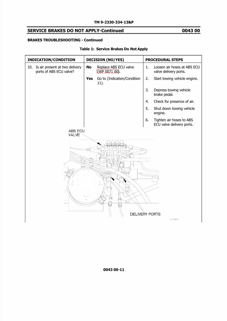
8/14/2019 TM 9-2330-334-13P M1147 FMTV-LHST TRAILER PART 2
http://slidepdf.com/reader/full/tm-9-2330-334-13p-m1147-fmtv-lhst-trailer-part-2 95/147
TM 9-2330-334-13&P
SERVICE BRAKES DO NOT APPLY-Continued 0043 00
BRAKES TROUBLESHOOTING - Continued
Table 1: Service Brakes Do Not Apply
0043 00-11
INDICATION/CONDITION DECISION (NO/YES) PROCEDURAL STEPS
10. Is air present at two deliveryports of ABS ECU valve?
No Replace ABS ECU valve(WP 0071 00).
1. Loosen air hoses at ABS ECUvalve delivery ports.
Yes Go to (Indication/Condition11).
2. Start towing vehicle engine.
3. Depress towing vehiclebrake pedal.
4. Check for presence of air.
5. Shut down towing vehicle
engine.
6. Tighten air hoses to ABSECU valve delivery ports.

8/14/2019 TM 9-2330-334-13P M1147 FMTV-LHST TRAILER PART 2
http://slidepdf.com/reader/full/tm-9-2330-334-13p-m1147-fmtv-lhst-trailer-part-2 96/147
TM 9-2330-334-13&P
SERVICE BRAKES DO NOT APPLY-Continued 0043 00
BRAKES TROUBLESHOOTING - Continued
Table 1: Service Brakes Do Not Apply
0043 00-12
INDICATION/CONDITION DECISION (NO/YES) PROCEDURAL STEPS
11. Is air present at control portof ABS relay valve?
No Replace air hose 103. 1. Loosen air hose 103 at ABSrelay valve control port.
Yes Go to (Indication/Condition12).
2. Start towing vehicle engine.
3. Depress towing vehiclebrake pedal.
4. Check for presence of air.
5. Shut down towing vehicle
engine.
6. Tighten air hose 103 to ABSrelay valve control port.

8/14/2019 TM 9-2330-334-13P M1147 FMTV-LHST TRAILER PART 2
http://slidepdf.com/reader/full/tm-9-2330-334-13p-m1147-fmtv-lhst-trailer-part-2 97/147
TM 9-2330-334-13&P
SERVICE BRAKES DO NOT APPLY-Continued 0043 00
BRAKES TROUBLESHOOTING - Continued
Table 1: Service Brakes Do Not Apply
0043 00-13
INDICATION/CONDITION DECISION (NO/YES) PROCEDURAL STEPS
12. Is air present at two deliveryport of ABS relay valve?
No Replace ABS relay valve(WP 0075 00).
1. Loosen air hoses at ABSrelay valve delivery ports.
Yes Go to (Indication/Condition13).
2. Start towing vehicle engine.
3. Depress towing vehiclebrake pedal.
4. Check for presence of air.
5. Shut down towing vehicle
engine.
6. Tighten air hoses to ABSrelay valve delivery ports.

8/14/2019 TM 9-2330-334-13P M1147 FMTV-LHST TRAILER PART 2
http://slidepdf.com/reader/full/tm-9-2330-334-13p-m1147-fmtv-lhst-trailer-part-2 98/147
TM 9-2330-334-13&P
SERVICE BRAKES DO NOT APPLY-Continued 0043 00
BRAKES TROUBLESHOOTING - Continued
Table 1: Service Brakes Do Not Apply
0043 00-14
INDICATION/CONDITION DECISION (NO/YES) PROCEDURAL STEPS
13. Is air present at service portof brake air chambers?
No Replace service brake airsupply hoses.
1. Loosen air hoses at serviceports of brake air chambers.
Yes Replace brake air chambers(WP 0081 00).
2. Start towing vehicle engine.
3. Depress towing vehiclebrake pedal.
4. Check for presence of air.
5. Shut down towing vehicle
engine.
6. Tighten air hoses to serviceports of brake air chambers.
END OF WORK PACKAGE

8/14/2019 TM 9-2330-334-13P M1147 FMTV-LHST TRAILER PART 2
http://slidepdf.com/reader/full/tm-9-2330-334-13p-m1147-fmtv-lhst-trailer-part-2 99/147
TM 9-2330-334-13&P
TRAILER BRAKES UNEVENLY OR BRAKES
PULL TO ONE SIDE OR GRAB 0044 00
THIS WORK PACKAGE COVERS:Brakes Troubleshooting
0044 00-1
INITIAL SETUP:
Maintenance LevelField
Tools/Special Tools Tool Kit, Genl Mech (Item 22, WP 0167 00) Jack, Dolly Type, Hydraulic (Item 10, WP
0167 00)
Materials/PartsTies, Cable, Plastic (Item 20, WP 0165 00)
Personnel Required Two
ReferencesTowing vehicle operators manual
Equipment Conditions
Air system charged (TM 9-2320-392-10-1)
PROCEDURE
WARNING
Remove rings, bracelets, watches, necklaces, and any other jewelry before workingaround vehicle. Jewelry can catch on equipment and cause injury or short acrosselectrical circuit and cause severe burns or electrical shock. Failure to comply mayresult in injury to personnel.
Wear appropriate eye protection when working under trailer due to possibility of falling debris and to protect from release of high pressure air. Failure to complymay result in injury to personnel.
NOTEReturn vehicle to mission capable condition and perform (Operational Checkout andTroubleshooting Procedures WP 0013 00) after a corrective action has been performed.
Tag hoses and connection points prior to disconnecting.
Remove plastic cable ties as required.
Reference pneumatic schematic at end of chapter as required.

8/14/2019 TM 9-2330-334-13P M1147 FMTV-LHST TRAILER PART 2
http://slidepdf.com/reader/full/tm-9-2330-334-13p-m1147-fmtv-lhst-trailer-part-2 100/147
TM 9-2330-334-13&P
TRAILER BRAKES UNEVENLY OR BRAKES
PULL TO ONE SIDE OR GRAB -Continued 0044 00
BRAKES TROUBLESHOOTING - Continued
Table 1: Trailer Brakes Unevenly Or Brakes Pull To One Side Or Grab
0044 00-2
INDICATION/CONDITION DECISION (NO/YES) PROCEDURAL STEPS
1. Is the TRAILER AIR SUPPLY knob on the towing vehiclepulled out?
No Go to (Indication/Condition2).
1. Check TRAILER AIR SUPPLY knob in cab to see if it isengaged.
Yes Push TRAILER AIR SUPPLY knob of towing vehicle tosupply air (TM 9-2320-392-10-1).
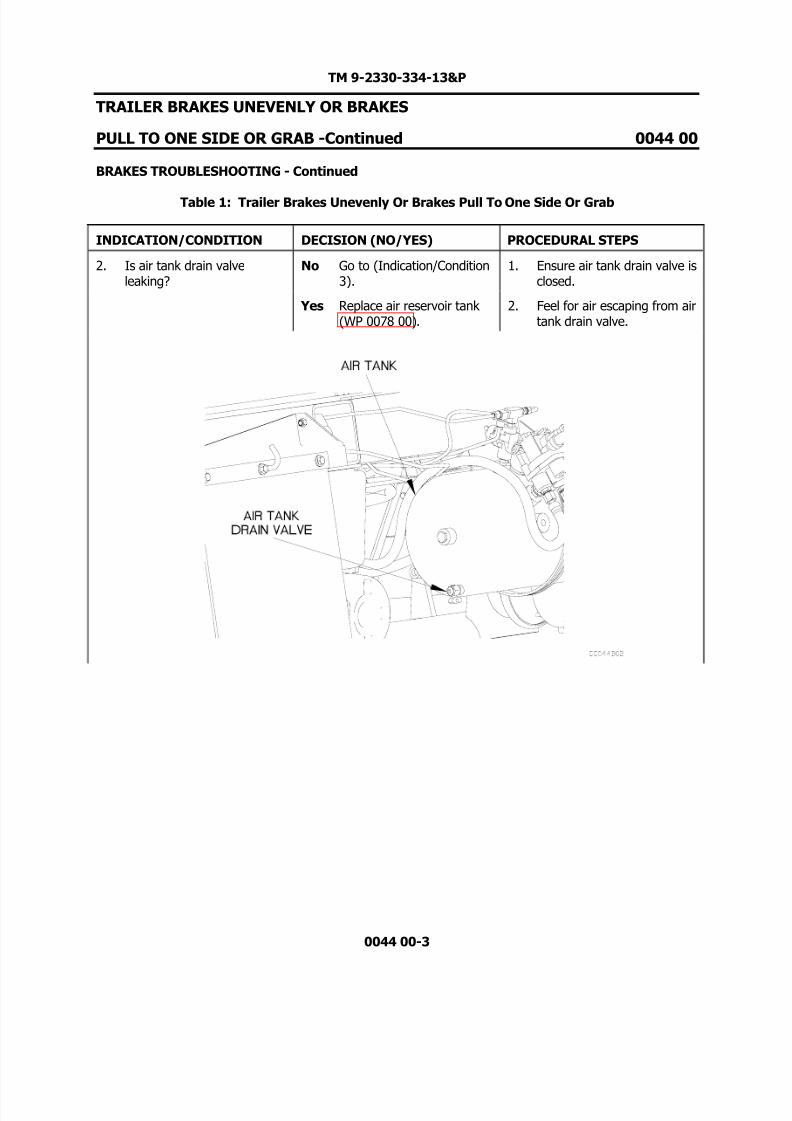
8/14/2019 TM 9-2330-334-13P M1147 FMTV-LHST TRAILER PART 2
http://slidepdf.com/reader/full/tm-9-2330-334-13p-m1147-fmtv-lhst-trailer-part-2 101/147
TM 9-2330-334-13&P
TRAILER BRAKES UNEVENLY OR BRAKES
PULL TO ONE SIDE OR GRAB -Continued 0044 00
BRAKES TROUBLESHOOTING - Continued
Table 1: Trailer Brakes Unevenly Or Brakes Pull To One Side Or Grab
0044 00-3
INDICATION/CONDITION DECISION (NO/YES) PROCEDURAL STEPS
2. Is air tank drain valveleaking?
No Go to (Indication/Condition3).
1. Ensure air tank drain valve isclosed.
Yes Replace air reservoir tank (WP 0078 00).
2. Feel for air escaping from airtank drain valve.

8/14/2019 TM 9-2330-334-13P M1147 FMTV-LHST TRAILER PART 2
http://slidepdf.com/reader/full/tm-9-2330-334-13p-m1147-fmtv-lhst-trailer-part-2 102/147
TM 9-2330-334-13&P
TRAILER BRAKES UNEVENLY OR BRAKES
PULL TO ONE SIDE OR GRAB -Continued 0044 00
BRAKES TROUBLESHOOTING - Continued
Table 1: Trailer Brakes Unevenly Or Brakes Pull To One Side Or Grab
0044 00-4
INDICATION/CONDITION DECISION (NO/YES) PROCEDURAL STEPS
3. Are brake shoes free fromcontamination, oil, andgrease?
No Replace wheel bearingseals (WP 0085 00).
1. Jack up axle of each affectedwheel/brake.
Yes Go to (Indication/Condition4).
2. Support axle assembly ontrestles.
3. Rotate wheel and check forcontamination of brake shoe
linings from leaking oil,grease or debris.

8/14/2019 TM 9-2330-334-13P M1147 FMTV-LHST TRAILER PART 2
http://slidepdf.com/reader/full/tm-9-2330-334-13p-m1147-fmtv-lhst-trailer-part-2 103/147
TM 9-2330-334-13&P
TRAILER BRAKES UNEVENLY OR BRAKES
PULL TO ONE SIDE OR GRAB -Continued 0044 00
BRAKES TROUBLESHOOTING - Continued
Table 1: Trailer Brakes Unevenly Or Brakes Pull To One Side Or Grab
0044 00-5
INDICATION/CONDITION DECISION (NO/YES) PROCEDURAL STEPS
4. Do individual wheels/brakeslockup or drag while applyingbrakes and manuallyspinning wheel?
No Go to (Indication/Condition5).
1. Start towing vehicle engine(EM 0195).
Yes Adjust brake shoeclearance (WP 0069 00).
2. Allow brake air pressure tofully charge.
3. Depress brake pedal.
4. Have assistant spin wheels,one at a time.
5. Shut down towing vehicleengine.

8/14/2019 TM 9-2330-334-13P M1147 FMTV-LHST TRAILER PART 2
http://slidepdf.com/reader/full/tm-9-2330-334-13p-m1147-fmtv-lhst-trailer-part-2 104/147
TM 9-2330-334-13&P
TRAILER BRAKES UNEVENLY OR BRAKES
PULL TO ONE SIDE OR GRAB -Continued 0044 00
BRAKES TROUBLESHOOTING - Continued
Table 1: Trailer Brakes Unevenly Or Brakes Pull To One Side Or Grab
0044 00-6
INDICATION/CONDITION DECISION (NO/YES) PROCEDURAL STEPS
5. Is air present at four porttask valve delivery port toaffected wheel(s)/brake(s)when brakes are applied?
No Replace four port task valve(WP 0109 00).
1. Remove trestles from axleassembly.
Yes Go to (Indication/Condition6).
2. Lower jack to place trailer onground.
3. Loosen air delivery hoses to
spring brakes at deliveryports of four port task valve.
4. Start towing vehicle engine.
5. Allow brake air pressure tofully charge.
6. Depress brake pedal andhave assistant check forpresence of air escaping atdelivery port of four porttask valve and air hoses.
7. Shut down towing vehicleengine.

8/14/2019 TM 9-2330-334-13P M1147 FMTV-LHST TRAILER PART 2
http://slidepdf.com/reader/full/tm-9-2330-334-13p-m1147-fmtv-lhst-trailer-part-2 105/147
TM 9-2330-334-13&P
TRAILER BRAKES UNEVENLY OR BRAKES
PULL TO ONE SIDE OR GRAB -Continued 0044 00
BRAKES TROUBLESHOOTING - Continued
Table 1: Trailer Brakes Unevenly Or Brakes Pull To One Side Or Grab
0044 00-7
INDICATION/CONDITION DECISION (NO/YES) PROCEDURAL STEPS
6. Is air present at emergencyport of brake air chamber of affected wheel(s)/brake(s)when brakes are applied?
No Replace damaged orblocked air hoses.
1. Tighten hoses at deliveryports of four port task valve.
Yes Go to (Indication/Condition7).
2. Loosen hoses at emergencyport of brake air chamber of affected wheel(s)/brake(s).
3. Start towing vehicle engine.
4. Allow brake air pressure tofully charge.
5. Depress brake pedal andhave assistant check forpresence of air escaping atemergency port of air brakechambers and air hoses.
6. Shut down towing vehicleengine.

8/14/2019 TM 9-2330-334-13P M1147 FMTV-LHST TRAILER PART 2
http://slidepdf.com/reader/full/tm-9-2330-334-13p-m1147-fmtv-lhst-trailer-part-2 106/147
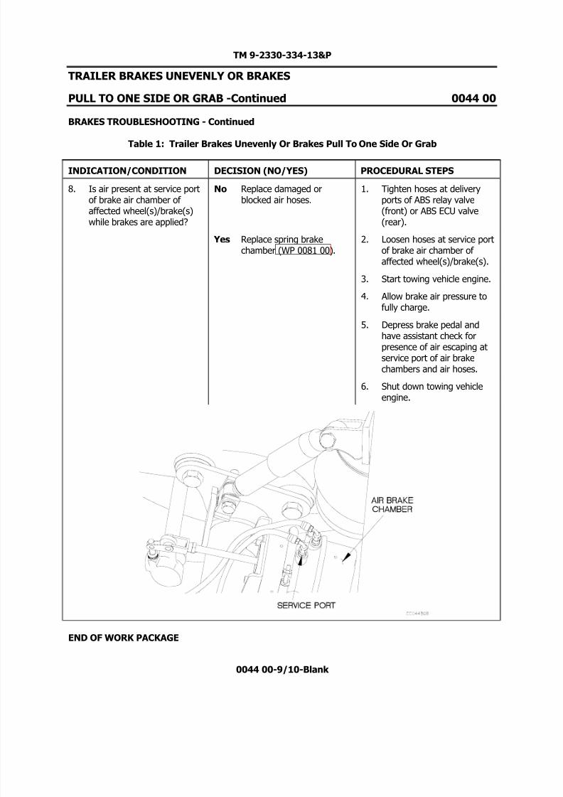
8/14/2019 TM 9-2330-334-13P M1147 FMTV-LHST TRAILER PART 2
http://slidepdf.com/reader/full/tm-9-2330-334-13p-m1147-fmtv-lhst-trailer-part-2 107/147
TM 9-2330-334-13&P
TRAILER BRAKES UNEVENLY OR BRAKES
PULL TO ONE SIDE OR GRAB -Continued 0044 00
BRAKES TROUBLESHOOTING - Continued
Table 1: Trailer Brakes Unevenly Or Brakes Pull To One Side Or Grab
0044 00-9/10-Blank
INDICATION/CONDITION DECISION (NO/YES) PROCEDURAL STEPS
8. Is air present at service portof brake air chamber of affected wheel(s)/brake(s)while brakes are applied?
No Replace damaged orblocked air hoses.
1. Tighten hoses at deliveryports of ABS relay valve(front) or ABS ECU valve(rear).
Yes Replace spring brakechamber (WP 0081 00).
2. Loosen hoses at service portof brake air chamber of affected wheel(s)/brake(s).
3. Start towing vehicle engine.
4. Allow brake air pressure tofully charge.
5. Depress brake pedal andhave assistant check forpresence of air escaping atservice port of air brakechambers and air hoses.
6. Shut down towing vehicleengine.
END OF WORK PACKAGE

8/14/2019 TM 9-2330-334-13P M1147 FMTV-LHST TRAILER PART 2
http://slidepdf.com/reader/full/tm-9-2330-334-13p-m1147-fmtv-lhst-trailer-part-2 108/147

8/14/2019 TM 9-2330-334-13P M1147 FMTV-LHST TRAILER PART 2
http://slidepdf.com/reader/full/tm-9-2330-334-13p-m1147-fmtv-lhst-trailer-part-2 109/147
TM 9-2330-334-13&P
SUSPENSION SYSTEM SITS UNEVEN 0045 00
THIS WORK PACKAGE COVERS:Pneumatic System troubleshooting.
0045 00-1
INITIAL SETUP:
Maintenance LevelField
Tools/Special Tools Gage, Pressure, 0-150 psi. (Item 5, WP 0167
00) Tool Kit, Genl Mech (Item 22, WP 0167 00) Goggles, Industrial (Item 8, WP 0167 00)
Materials/PartsTies, Cable, Plastic (Item 20, WP 0165 00) Soap, Laundry (Item 16, WP 0165 00) Bushing, Pipe (Item 4, WP 0165 00)
Personnel Required Two
Equipment ConditionsTrailer air system charged (TM 9-2320-392-
10-1)
PROCEDURE
WARNING
Wear appropriate eye protection when working under vehicle due to the possibilityof falling debris. Failure to comply may result in injury to personnel.
NOTE
Return vehicle to mission capable condition and perform (Operational Checkout andTroubleshooting Procedures WP 0013 00) after a corrective action has been performed.
Tag hoses and connection points prior to disconnecting.
Remove plastic cable ties as required.
Select the appropriate fault to determine where troubleshooting continues:1. One air spring does not inflate (Table 1, Indication/Condition 1).2. Rear air springs do not inflate (Table 1, Indication/Condition 2).3. Front Suspension Does Not Raise/Lower (WP 0047 00).

8/14/2019 TM 9-2330-334-13P M1147 FMTV-LHST TRAILER PART 2
http://slidepdf.com/reader/full/tm-9-2330-334-13p-m1147-fmtv-lhst-trailer-part-2 110/147
TM 9-2330-334-13&P
SUSPENSION SYSTEM SITS UNEVEN-Continued 0045 00
PNEUMATIC SYSTEM TROUBLESHOOTING - Continued
Table 1. Uneven Suspension System
0045 00-2
INDICATION/CONDITION DECISION (NO/YES) PROCEDURAL STEPS
1. Is air present at affected airspring?
No. Replace air hose from airspring to tee fitting.
1. Drain air tanks (WP 000400)
Yes. Replace air bladder (WP0096 00).
2. Disconnect air hose from 90-degree fitting.
3. Charge air system (EM0195).
4. Check for the presents of airfrom open air hose.

8/14/2019 TM 9-2330-334-13P M1147 FMTV-LHST TRAILER PART 2
http://slidepdf.com/reader/full/tm-9-2330-334-13p-m1147-fmtv-lhst-trailer-part-2 111/147
TM 9-2330-334-13&P
SUSPENSION SYSTEM SITS UNEVEN-Continued 0045 00
PNEUMATIC SYSTEM TROUBLESHOOTING - Continued
Table 1. Uneven Suspension System
0045 00-3
INDICATION/CONDITION DECISION (NO/YES) PROCEDURAL STEPS
2. Does rear air hoses orfittings have air leaks?
No. Go to (Indication/Condition3).
1. With the use of a soapywater solution check forbubbles indicating air leaks.
Yes. Replace leaking hose(s)and/or fittings.
3. Is brake protection valvefilter free from damage orobstructions?
No. Clean or replace brakeprotection valve filter (WP0075 00).
1. Remove filter from brakeprotection valve (WP 007500) and check for damageor obstructions.
Yes. Go to (Indication/Condition4).
4. Does brake protection valveoperate properly?
No. Replace brake protectionvalve (WP 0075 00).
1. Drain rear air tank.
Yes. Go to (Indication/Condition5).
2. Remove ½ in. plug fromrear air tank.
3. Install pipe bushing andpressure gage in air tank.

8/14/2019 TM 9-2330-334-13P M1147 FMTV-LHST TRAILER PART 2
http://slidepdf.com/reader/full/tm-9-2330-334-13p-m1147-fmtv-lhst-trailer-part-2 112/147
TM 9-2330-334-13&P
SUSPENSION SYSTEM SITS UNEVEN-Continued 0045 00
PNEUMATIC SYSTEM TROUBLESHOOTING - Continued
Table 1. Uneven Suspension System
0045 00-4
INDICATION/CONDITION DECISION (NO/YES) PROCEDURAL STEPS
4. Does brake protection valveoperate properly? (Cont)
No. Replace brake protectionvalve (WP 0075 00).
4. Disconnect air hose from teefitting.
Yes. Go to (Indication/Condition5).
5. Begin pressurizing airsystem and note if brakeprotection valve opens at70-75 psi. indicating properoperation.
6. Drain air tank and note if brake protection valve
closes at 60-65 psi.indicating proper operation.
7. Connect air hose to teefitting.
8. Remove pressure gage andpipe bushing from air tank.
9. Install ½ inch plug in airtank.
5. Does height control valveoperate properly?
No. Replace height controlvalve (WP 0084 00).
1. Check height control valvefor proper installation andoperation (WP 0084 00).
Yes. Properly adjust linkage (WP0084 00).
END OF WORK PACKAGE
8/14/2019 TM 9-2330-334-13P M1147 FMTV-LHST TRAILER PART 2
http://slidepdf.com/reader/full/tm-9-2330-334-13p-m1147-fmtv-lhst-trailer-part-2 113/147
TM 9-2330-334-13&P
SUSPENSION SYSTEM DOES NOT SUPPORT TRAILER LOAD 0046 00
THIS WORK PACKAGE COVERS:Pneumatic Troubleshooting
0046 00-1/2-Blank
INITIAL SETUP:
Maintenance LevelField
Tools/Special Tools Tool Kit, Genl Mech (Item 22, WP 0167 00)
Materials/PartsTies, Cable, Plastic (Item 20, WP 0165 00) Soap, Laundry (Item 16, WP 0165 00).
Personnel Required Two
Equipment ConditionsTrailer air system charged (TM 9-2320-392-
10-1)
PROCEDURE
WARNING
Wear appropriate eye protection when working under trailer due to possibility of falling debris and to protect from release of high pressure air. Failure to complymay result in injury to personnel.
NOTEReturn vehicle to mission capable condition and perform (Operational Checkout andTroubleshooting Procedures WP 0013 00) after a corrective action has been performed.
1. Perform WP 0042 00 before proceeding to step 2.
2. Replace shock absorber(s) (WP 0095 00).
END OF WORK PACKAGE

8/14/2019 TM 9-2330-334-13P M1147 FMTV-LHST TRAILER PART 2
http://slidepdf.com/reader/full/tm-9-2330-334-13p-m1147-fmtv-lhst-trailer-part-2 114/147

8/14/2019 TM 9-2330-334-13P M1147 FMTV-LHST TRAILER PART 2
http://slidepdf.com/reader/full/tm-9-2330-334-13p-m1147-fmtv-lhst-trailer-part-2 115/147
TM 9-2330-334-13&P
FRONT SUSPENSION DOES NOT RAISE/LOWER 0047 00
THIS WORK PACKAGE COVERS:Pneumatic Troubleshooting
0047 00-1
INITIAL SETUP:
Maintenance LevelField
Tools/Special Tools Tool Kit, Genl Mech (Item 22, WP 0167 00)
Materials/PartsTies, Cable, Plastic (Item 20, WP 0165 00) Soap, Laundry (Item 16, WP 0165 00)
Personnel Required Two
Equipment ConditionsTrailer air system charged (TM 9-2320-392-
10)
PROCEDURE
WARNING
Remove rings, bracelets, watches, necklaces, and any other jewelry before workingaround vehicle. Jewelry can catch on equipment and cause injury or short acrosselectrical circuit and cause severe burns or electrical shock. Failure to comply mayresult in injury to personnel.
Wear appropriate eye protection when working under trailer due to possibility of falling debris and to protect from release of high pressure air. Failure to complymay result in injury to personnel.
Wear protective goggles to protect against possible injury from release of highpressure air. Failure to comply may result in injury to personnel.
NOTEReturn vehicle to mission capable condition and perform (Operational Checkout andTroubleshooting Procedures WP 0013 00) after a corrective action has been performed.
Tag hoses and connection points prior to disconnecting.
Remove plastic cable ties as required.

8/14/2019 TM 9-2330-334-13P M1147 FMTV-LHST TRAILER PART 2
http://slidepdf.com/reader/full/tm-9-2330-334-13p-m1147-fmtv-lhst-trailer-part-2 116/147
TM 9-2330-334-13&P
FRONT SUSPENSION DOES NOT RAISE/LOWER -Continued 0047 00
PNEUMATIC TROUBLESHOOTING - Continued
Table 1: Front Suspension Does Not Raise/Lower
0047 00-2
INDICATION/CONDITION DECISION (NO/YES) PROCEDURAL STEPS
1. Does front suspension fail toraise or lower?
Raise Go to (Indication/Condition6).
1. Charge air system and noteif front suspension will raise.
Lower Go to(Indication/Condition 2).
2. Push in height actuationvalve handle and note if front suspension will lower.

8/14/2019 TM 9-2330-334-13P M1147 FMTV-LHST TRAILER PART 2
http://slidepdf.com/reader/full/tm-9-2330-334-13p-m1147-fmtv-lhst-trailer-part-2 117/147
TM 9-2330-334-13&P
FRONT SUSPENSION DOES NOT RAISE/LOWER -Continued 0047 00
PNEUMATIC TROUBLESHOOTING - Continued
Table 1: Front Suspension Does Not Raise/Lower
0047 00-3
INDICATION/CONDITION DECISION (NO/YES) PROCEDURAL STEPS
2. Is air present at hose 007connection point on air ridecontrol valve?
No Go to (Indication/Condition3).
1. Disconnect hose 007 fromair ride control valve.
Yes Go to (Indication/Condition4).
2. Push height actuation valvehandle in and feel for airescaping from end of hose007.

8/14/2019 TM 9-2330-334-13P M1147 FMTV-LHST TRAILER PART 2
http://slidepdf.com/reader/full/tm-9-2330-334-13p-m1147-fmtv-lhst-trailer-part-2 118/147
TM 9-2330-334-13&P
FRONT SUSPENSION DOES NOT RAISE/LOWER -Continued 0047 00
PNEUMATIC TROUBLESHOOTING - Continued
Table 1: Front Suspension Does Not Raise/Lower
0047 00-4
INDICATION/CONDITION DECISION (NO/YES) PROCEDURAL STEPS
3. Does air hose 010 have anykinks, leaks, or holes?
No Replace height actuationvalve (WP 0110 00).
1. Apply soapy water solutionto air hose 010 and fittings.
Yes Replace hose 010. 2. Push in handle on heightactuation valve and check airhose 010 between brakeprotection valve and heightactuation valve for bubblesindicating holes or leaks.
3. Check hose 010 for kinks.

8/14/2019 TM 9-2330-334-13P M1147 FMTV-LHST TRAILER PART 2
http://slidepdf.com/reader/full/tm-9-2330-334-13p-m1147-fmtv-lhst-trailer-part-2 119/147
TM 9-2330-334-13&P
FRONT SUSPENSION DOES NOT RAISE/LOWER -Continued 0047 00
PNEUMATIC TROUBLESHOOTING - Continued
Table 1: Front Suspension Does Not Raise/Lower
0047 00-5
INDICATION/CONDITION DECISION (NO/YES) PROCEDURAL STEPS
4. Is air present at air ridecontrol valve connection airhose 004?
No Replace air ride controlvalve (WP 0080 00).
1. Disconnect air hose 004 atconnection point on air ridecontrol valve.
Yes Go to (Indication/Condition5).
2. Push height actuation valvehandle in and feel for airescaping from connectionpoint on air ride controlvalve.

8/14/2019 TM 9-2330-334-13P M1147 FMTV-LHST TRAILER PART 2
http://slidepdf.com/reader/full/tm-9-2330-334-13p-m1147-fmtv-lhst-trailer-part-2 120/147
TM 9-2330-334-13&P
FRONT SUSPENSION DOES NOT RAISE/LOWER -Continued 0047 00
PNEUMATIC TROUBLESHOOTING - Continued
Table 1: Front Suspension Does Not Raise/Lower
0047 00-6
INDICATION/CONDITION DECISION (NO/YES) PROCEDURAL STEPS
5. Does air hose 004 have anykinks?
No Replace breather valve (WP0082 00).
1. Connect air hose 004 atconnection point on air ridecontrol valve.
Yes Replace air hose 004. 2. Lift turntable from frame foraccess (WP 0099 00).
3. Follow path of air hose 004from air ride control valve tobreather valve to check forany kinks in air hose.
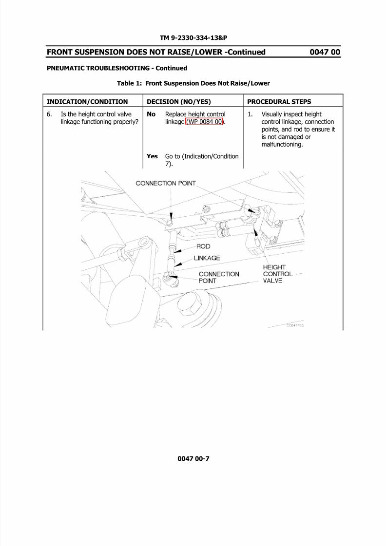
8/14/2019 TM 9-2330-334-13P M1147 FMTV-LHST TRAILER PART 2
http://slidepdf.com/reader/full/tm-9-2330-334-13p-m1147-fmtv-lhst-trailer-part-2 121/147
TM 9-2330-334-13&P
FRONT SUSPENSION DOES NOT RAISE/LOWER -Continued 0047 00
PNEUMATIC TROUBLESHOOTING - Continued
Table 1: Front Suspension Does Not Raise/Lower
0047 00-7
INDICATION/CONDITION DECISION (NO/YES) PROCEDURAL STEPS
6. Is the height control valvelinkage functioning properly?
No Replace height controllinkage (WP 0084 00).
1. Visually inspect heightcontrol linkage, connectionpoints, and rod to ensure itis not damaged ormalfunctioning.
Yes Go to (Indication/Condition7).

8/14/2019 TM 9-2330-334-13P M1147 FMTV-LHST TRAILER PART 2
http://slidepdf.com/reader/full/tm-9-2330-334-13p-m1147-fmtv-lhst-trailer-part-2 122/147
TM 9-2330-334-13&P
FRONT SUSPENSION DOES NOT RAISE/LOWER -Continued 0047 00
PNEUMATIC TROUBLESHOOTING - Continued
Table 1: Front Suspension Does Not Raise/Lower
0047 00-8
INDICATION/CONDITION DECISION (NO/YES) PROCEDURAL STEPS
7. Is air present at outlet portof height control valve?
No Go to (Indication/Condition8).
1. Disconnect air hose 008from outlet port of heightcontrol valve.
Yes Go to (Indication/Condition9).
2. Attempt to charge air system(TM 9-2320-392-10).
3. Listen and feel for airdischarging from outlet porton height control valve.

8/14/2019 TM 9-2330-334-13P M1147 FMTV-LHST TRAILER PART 2
http://slidepdf.com/reader/full/tm-9-2330-334-13p-m1147-fmtv-lhst-trailer-part-2 123/147
TM 9-2330-334-13&P
FRONT SUSPENSION DOES NOT RAISE/LOWER -Continued 0047 00
PNEUMATIC TROUBLESHOOTING - Continued
Table 1: Front Suspension Does Not Raise/Lower
0047 00-9
INDICATION/CONDITION DECISION (NO/YES) PROCEDURAL STEPS
8. Does air hose 009 have anykinks, leaks or holes?
No Replace height controlvalve (WP 0084 00).
1. Connect air hose 008 tooutlet port of height controlvalve.
Yes Replace air hose 009. 2. Apply soapy water solutionto air hose 009 and fittings.
3. Attempt to charge air system(TM 9-2320-392-10).
4. Check air hose 009 fromheight control valve to brakeprotection valve for anybubbles indicating leaks orholes.

8/14/2019 TM 9-2330-334-13P M1147 FMTV-LHST TRAILER PART 2
http://slidepdf.com/reader/full/tm-9-2330-334-13p-m1147-fmtv-lhst-trailer-part-2 124/147
TM 9-2330-334-13&P
FRONT SUSPENSION DOES NOT RAISE/LOWER -Continued 0047 00
PNEUMATIC TROUBLESHOOTING - Continued
Table 1: Front Suspension Does Not Raise/Lower
0047 00-10
INDICATION/CONDITION DECISION (NO/YES) PROCEDURAL STEPS
9. Does air hose 008 have anykinks, leaks or holes?
No Go to (Indication/Condition10).
1. Connect air hose 008 tooutlet port of height controlvalve.
Yes Replace air hose 008. 2. Apply soapy water solutionto air hose 008 and fittings.
3. Attempt to charge air system(TM 9-2320-392-10).
4. Check air hose 008 fromheight control valve to airride control valve for anybubbles indicating leaks orholes.

8/14/2019 TM 9-2330-334-13P M1147 FMTV-LHST TRAILER PART 2
http://slidepdf.com/reader/full/tm-9-2330-334-13p-m1147-fmtv-lhst-trailer-part-2 125/147
TM 9-2330-334-13&P
FRONT SUSPENSION DOES NOT RAISE/LOWER -Continued 0047 00
PNEUMATIC TROUBLESHOOTING - Continued
Table 1: Front Suspension Does Not Raise/Lower
0047 00-11/12-Blank
INDICATION/CONDITION DECISION (NO/YES) PROCEDURAL STEPS
10. Is air present at outlet portof air ride control valve?
No Replace air ride controlvalve (WP 0080 00).
1. Disconnect air hose 005 andair hose 006 from outlet porton air ride control valve.
Yes Replace air hose 005. 2. Attempt to charge air system(TM 9-2320-392-10).
3. Listen and feel for airdischarging from outlet porton air ride control valve.
END OF WORK PACKAGE

8/14/2019 TM 9-2330-334-13P M1147 FMTV-LHST TRAILER PART 2
http://slidepdf.com/reader/full/tm-9-2330-334-13p-m1147-fmtv-lhst-trailer-part-2 126/147
8/14/2019 TM 9-2330-334-13P M1147 FMTV-LHST TRAILER PART 2
http://slidepdf.com/reader/full/tm-9-2330-334-13p-m1147-fmtv-lhst-trailer-part-2 127/147
TM 9-2330-334-13&P
RAIL ASSEMBLY DOES NOT RAISE/LOWER 0048 00
THIS WORK PACKAGE COVERS:Rail Assembly Troubleshooting
0048 00-1
INITIAL SETUP:
Maintenance LevelField
Tools/Special Tools Tool Kit, Genl Mech (Item 22, WP 0167 00)
Materials/PartsTies, Cable, Plastic (Item 20, WP 0165 00)
Personnel Required Two
Equipment ConditionsRail lock pin removed (WP 0005 00) Rail lift jack handle installed (WP 0005 00)
PROCEDURE
WARNING
Remove rings, bracelets, watches, necklaces, and any other jewelry before workingaround vehicle. Jewelry can catch on equipment and cause injury or short acrosselectrical circuit and cause severe burns or electrical shock. Failure to comply mayresult in injury to personnel.
Ensure rail assembly is in a secure position and cannot fall or shift onto personnel.Failure to comply may result in injury to personnel.
CAUTION
Ensure no corrosion, debris or any obstruction is present in rail guide tracks that would preventrail assembly from operating properly. Failure to comply may result in damage to equipment.
NOTEReturn vehicle to mission capable condition and perform (Operational Checkout andTroubleshooting Procedures WP 0013 00) after a corrective action has been performed.

8/14/2019 TM 9-2330-334-13P M1147 FMTV-LHST TRAILER PART 2
http://slidepdf.com/reader/full/tm-9-2330-334-13p-m1147-fmtv-lhst-trailer-part-2 128/147
TM 9-2330-334-13&P
RAIL ASSEMBLY DOES NOT RAISE/LOWER -Continued 0048 00
RAIL ASSEMBLY TROUBLESHOOTING - Continued
Table 1: Rail Assembly Does Not Raise/Lower
0048 00-2
INDICATION/CONDITION DECISION (NO/YES) PROCEDURAL STEPS
1. Is rail lift jack spinningfreely?
No. Replace rail assembly (WP0089 00).
1. Remove shuttle lock pins.
Yes. Replace rail lift jack (WP0102 00).
2. Push knob of flatrack lock control to release flatrack locks.
3. Turn rail lift jack handle.
4. Check to see if handle willspin freely.
END OF WORK PACKAGE

8/14/2019 TM 9-2330-334-13P M1147 FMTV-LHST TRAILER PART 2
http://slidepdf.com/reader/full/tm-9-2330-334-13p-m1147-fmtv-lhst-trailer-part-2 129/147
TM 9-2330-334-13&P
FLATRACK LOCKS DO NOT RELEASE/LOCK 0049 00
THIS WORK PACKAGE COVERS:Pneumatic Troubleshooting
0049 00-1
INITIAL SETUP:
Maintenance LevelField
Tools/Special Tools Tool Kit, Genl Mech (Item 22, WP 0167 00)
Materials/PartsTies, Cable, Plastic (Item 20, WP 0165 00) Soap, Laundry (Item 16, WP 0165 00)
Personnel Required Two
Equipment Conditions Air system charged (TM 9-2320-392-10)Trailer unloaded (TM 9-2320-392-10)Rail assembly raised (WP 0005 00)
ReferencesTM 9-2320-392-10
PROCEDURE
WARNING
Remove rings, bracelets, watches, necklaces, and any other jewelry before workingaround vehicle. Jewelry can catch on equipment and cause injury or short acrosselectrical circuit and cause severe burns or electrical shock. Failure to comply mayresult in injury to personnel.
Wear appropriate eye protection when working under trailer due to possibility of falling debris. Failure to comply may result in injury to personnel.
NOTEReturn vehicle to mission capable condition and perform (Operational Checkout andTroubleshooting Procedures WP 0013 00) after a corrective action has been performed.
Tag hoses and connection points prior to disconnecting.
Remove plastic cable ties as required.

8/14/2019 TM 9-2330-334-13P M1147 FMTV-LHST TRAILER PART 2
http://slidepdf.com/reader/full/tm-9-2330-334-13p-m1147-fmtv-lhst-trailer-part-2 130/147
TM 9-2330-334-13&P
FLATRACK LOCKS DO NOT RELEASE/LOCK -Continued 0049 00
PNEUMATIC TROUBLESHOOTING - Continued
Table 1: Flatrack Locks Do Not Release/Engage
0049 00-2
INDICATION/CONDITION DECISION (NO/YES) PROCEDURAL STEPS
1. Do flatrack locks not releaseor lock?
Lock. Go to (Indication/Condition2).
1. Disengage DIN blockingplates from flatrack locks.
Release. Go to(Indictation/Condition 5).
2. Push or pull handle of flatrack lock controlpush/pull valve to testfunction of flatrack locks.

8/14/2019 TM 9-2330-334-13P M1147 FMTV-LHST TRAILER PART 2
http://slidepdf.com/reader/full/tm-9-2330-334-13p-m1147-fmtv-lhst-trailer-part-2 131/147
TM 9-2330-334-13&P
FLATRACK LOCKS DO NOT RELEASE/LOCK -Continued 0049 00
PNEUMATIC TROUBLESHOOTING - Continued
Table 1: Flatrack Locks Do Not Release/Engage
0049 00-3
INDICATION/CONDITION DECISION (NO/YES) PROCEDURAL STEPS
2. Is air pressure present atoutlet port of flatrack lock push/pull valve?
No. Go to (Indication/Condition3).
1. Disconnect air hose 107from flatrack lock push/pullvalve.
Yes. Go to (Indication/Condition4).
2. Pull handle of flatrack lock push/pull valve out and feelfor air escaping from outletport.

8/14/2019 TM 9-2330-334-13P M1147 FMTV-LHST TRAILER PART 2
http://slidepdf.com/reader/full/tm-9-2330-334-13p-m1147-fmtv-lhst-trailer-part-2 132/147
TM 9-2330-334-13&P
FLATRACK LOCKS DO NOT RELEASE/LOCK -Continued 0049 00
PNEUMATIC TROUBLESHOOTING - Continued
Table 1: Flatrack Locks Do Not Release/Engage
0049 00-4
INDICATION/CONDITION DECISION (NO/YES) PROCEDURAL STEPS
3. Does air hose 106 have anykinks, leaks, or holes?
No. Replace flatrack lock push/pull valve (WP 010800).
1. Connect air hose 107 toflatrack lock push/pull valve.
Yes. Replace air hose 106. 2. Apply soapy water to airhose 106 and connectionpoints.
3. Pull handle of flatrack lock push/pull valve out.
4. Look for bubbles escapingfrom hose indicating leaksand examine hose for kinks.

8/14/2019 TM 9-2330-334-13P M1147 FMTV-LHST TRAILER PART 2
http://slidepdf.com/reader/full/tm-9-2330-334-13p-m1147-fmtv-lhst-trailer-part-2 133/147
TM 9-2330-334-13&P
FLATRACK LOCKS DO NOT RELEASE/LOCK -Continued 0049 00
PNEUMATIC TROUBLESHOOTING - Continued
Table 1: Flatrack Locks Do Not Release/Engage
0049 00-5
INDICATION/CONDITION DECISION (NO/YES) PROCEDURAL STEPS
4. Does air hose 107 have anykinks, leaks, or holes?
No. Replace flatrack airchamber (WP 0107 00).
1. Connect air hose 107 toflatrack lock push/pull valve.
Yes. Replace air hose 107. 2. Apply soapy water to airhose 107 and connectionpoints.
3. Pull handle of flatrack lock push/pull valve out.
4. Look for bubbles escapingfrom hose indicating leaksand examine hose for kinks.

8/14/2019 TM 9-2330-334-13P M1147 FMTV-LHST TRAILER PART 2
http://slidepdf.com/reader/full/tm-9-2330-334-13p-m1147-fmtv-lhst-trailer-part-2 134/147
TM 9-2330-334-13&P
FLATRACK LOCKS DO NOT RELEASE/LOCK -Continued 0049 00
PNEUMATIC TROUBLESHOOTING - Continued
Table 1: Flatrack Locks Do Not Release/Engage
0049 00-6
INDICATION/CONDITION DECISION (NO/YES) PROCEDURAL STEPS
5. Is air pressure present atport on flatrack push/pullvalve at hose 013connection?
No. Go to (Indication/Condition6).
1. Disconnect air hose 013from flatrack lock push/pullvalve.
Yes. Go to (Indication/Condition7).
2. Push handle of flatrack lock push/pull valve in.
3. Feel for air escaping fromopen port on flatrack lock push/pull valve.
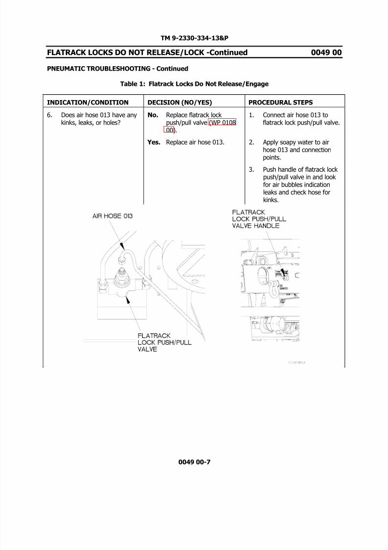
8/14/2019 TM 9-2330-334-13P M1147 FMTV-LHST TRAILER PART 2
http://slidepdf.com/reader/full/tm-9-2330-334-13p-m1147-fmtv-lhst-trailer-part-2 135/147

8/14/2019 TM 9-2330-334-13P M1147 FMTV-LHST TRAILER PART 2
http://slidepdf.com/reader/full/tm-9-2330-334-13p-m1147-fmtv-lhst-trailer-part-2 136/147
TM 9-2330-334-13&P
FLATRACK LOCKS DO NOT RELEASE/LOCK -Continued 0049 00
PNEUMATIC TROUBLESHOOTING - Continued
Table 1: Flatrack Locks Do Not Release/Engage
0049 00-8
INDICATION/CONDITION DECISION (NO/YES) PROCEDURAL STEPS
7. Is air pressure present atend of air hose 012 atconnection on breathervalve?
No. Go to (Indication/Condition8).
1. Connect air hose 013 toflatrack lock push/pull valve.
Yes. Replace breather valve (WP0082 00).
2. Remove LH compositetaillight for access tobreather valve.
3. Disconnect air hose 012from breather valve.
4. Push handle of flatrack lock push/pull valve in and feelfor air escaping from airhose 012.

8/14/2019 TM 9-2330-334-13P M1147 FMTV-LHST TRAILER PART 2
http://slidepdf.com/reader/full/tm-9-2330-334-13p-m1147-fmtv-lhst-trailer-part-2 137/147
TM 9-2330-334-13&P
FLATRACK LOCKS DO NOT RELEASE/LOCK -Continued 0049 00
PNEUMATIC TROUBLESHOOTING - Continued
Table 1: Flatrack Locks Do Not Release/Engage
0049 00-9/10-Blank
INDICATION/CONDITION DECISION (NO/YES) PROCEDURAL STEPS
8. Does air hose 012 have anykinks, leaks, or holes?
No. Replace flatrack airchamber (WP 0107 00).
1. Connect air hose 012 tobreather valve.
Yes. Replace air hose 012. 2. Apply soapy water to airhose 012 and connectionpoints.
3. Push handle of flatrack lock push/pull valve in.
4. Look for bubbles on air hose012 indication air escapingfrom air hose 012.
END OF WORK PACKAGE

8/14/2019 TM 9-2330-334-13P M1147 FMTV-LHST TRAILER PART 2
http://slidepdf.com/reader/full/tm-9-2330-334-13p-m1147-fmtv-lhst-trailer-part-2 138/147

8/14/2019 TM 9-2330-334-13P M1147 FMTV-LHST TRAILER PART 2
http://slidepdf.com/reader/full/tm-9-2330-334-13p-m1147-fmtv-lhst-trailer-part-2 139/147
TM 9-2330-334-13&P
DRAWBAR DOES NOT RAISE/LOWER 0050 00
THIS WORK PACKAGE COVERS:Pneumatic Troubleshooting
0050 00-1
INITIAL SETUP:
Maintenance LevelField
Tools/Special Tools Tool Kit, Genl Mech (Item 22, WP 0167 00)
Materials/PartsTies, Cable, Plastic (Item 20, WP 0165 00) Soap, Laundry (Item 16, WP 0165 00)
Personnel Required Two
Equipment Conditions Air tanks charged (TM 9-2320-392-10)
ReferencesTM 9-2320-392-10
PROCEDURE
WARNING
Remove rings, bracelets, watches, necklaces, and any other jewelry before workingaround vehicle. Jewelry can catch on equipment and cause injury or short acrosselectrical circuit and cause severe burns or electrical shock. Failure to comply mayresult in injury to personnel.
WARNING
Wear appropriate eye protection when working under trailer due to possibility of falling debris. Failure to comply may result in injury to personnel.
NOTEReturn vehicle to mission capable condition and perform (Operational Checkout Work PackageWP 0013 00) after a corrective action has been performed.
Tag hoses and connection points prior to disconnecting.
Remove plastic cable ties as required.

8/14/2019 TM 9-2330-334-13P M1147 FMTV-LHST TRAILER PART 2
http://slidepdf.com/reader/full/tm-9-2330-334-13p-m1147-fmtv-lhst-trailer-part-2 140/147
TM 9-2330-334-13&P
DRAWBAR DOES NOT RAISE/LOWER -Continued 0050 00
PNEUMATIC TROUBLESHOOTING - Continued
Table 1: Drawbar Does Not Raise/Lower
0050 00-2
INDICATION/CONDITION DECISION (NO/YES) PROCEDURAL STEPS
1. Does front suspension raiseand lower?
No Proceed to SuspensionSystem Sits Uneven (WP0045 00).
1. Push in height control valveknob.
Yes Go to (Indication/Condition2).
2. Look to see if frontsuspension will lower.
3. Pull out height control knob.
4. Look to see if frontsuspension will raise.

8/14/2019 TM 9-2330-334-13P M1147 FMTV-LHST TRAILER PART 2
http://slidepdf.com/reader/full/tm-9-2330-334-13p-m1147-fmtv-lhst-trailer-part-2 141/147
TM 9-2330-334-13&P
DRAWBAR DOES NOT RAISE/LOWER -Continued 0050 00
PNEUMATIC TROUBLESHOOTING - Continued
Table 1: Drawbar Does Not Raise/Lower
0050 00-3
INDICATION/CONDITION DECISION (NO/YES) PROCEDURAL STEPS
2. Does the drawbar not raiseor lower?
Won’t Raise Go to(Indication/Condition 3).
1. Raise drawbar lift controlhandle up to see if drawbarwill raise.
Won’t Lower Go to(Indication/Condition 4).
2. Lower drawbar lift controlhandle down to see if drawbar will lower.

8/14/2019 TM 9-2330-334-13P M1147 FMTV-LHST TRAILER PART 2
http://slidepdf.com/reader/full/tm-9-2330-334-13p-m1147-fmtv-lhst-trailer-part-2 142/147
TM 9-2330-334-13&P
DRAWBAR DOES NOT RAISE/LOWER -Continued 0050 00
PNEUMATIC TROUBLESHOOTING - Continued
Table 1: Drawbar Does Not Raise/Lower
0050 00-4
INDICATION/CONDITION DECISION (NO/YES) PROCEDURAL STEPS
3. Is air pressure present atdrawbar lift control port A?
No Go to (Indication/Condition5).
1. Disconnect connector onport A from drawbar liftcontrol valve.
Yes Go to (Indication/Condition6).
2. Lift handle on drawbar liftcontrol valve.
3. Listen and feel for airescaping from port A.

8/14/2019 TM 9-2330-334-13P M1147 FMTV-LHST TRAILER PART 2
http://slidepdf.com/reader/full/tm-9-2330-334-13p-m1147-fmtv-lhst-trailer-part-2 143/147
TM 9-2330-334-13&P
DRAWBAR DOES NOT RAISE/LOWER -Continued 0050 00
PNEUMATIC TROUBLESHOOTING - Continued
Table 1: Drawbar Does Not Raise/Lower
0050 00-5
INDICATION/CONDITION DECISION (NO/YES) PROCEDURAL STEPS
4. Is air pressure present atport EA of drawbar liftcontrol valve?
No Replace drawbar lift controlvalve (WP 0094 00).
1. Disconnect hose 002 fromport EA on drawbar liftcontrol valve.
Yes Replace breather valve (WP0082 00).
2. Lower handle on drawbar liftcontrol valve.
3. Listen and feel for airescaping from port EA ondrawbar lift control valve.
4. Release handle of drawbarlift control valve.

8/14/2019 TM 9-2330-334-13P M1147 FMTV-LHST TRAILER PART 2
http://slidepdf.com/reader/full/tm-9-2330-334-13p-m1147-fmtv-lhst-trailer-part-2 144/147
TM 9-2330-334-13&P
DRAWBAR DOES NOT RAISE/LOWER -Continued 0050 00
PNEUMATIC TROUBLESHOOTING - Continued
Table 1: Drawbar Does Not Raise/Lower
0050 00-6
INDICATION/CONDITION DECISION (NO/YES) PROCEDURAL STEPS
5. Does air hose 001 have anykinks, holes, leaks?
No Replace brake protectionvalve (WP 0075 00).
1. Connect hose 003 todrawbar lift control valveport A.
Yes Replace air hose 001. 2. Apply soapy water solutionto air hose 001, fittings, andport P.
3. Check air hose 001 betweendrawbar lift control valveand brake protection valve
for bubbles indicating holesor leaks.
4. Check fittings for bubblesindicating leaks.

8/14/2019 TM 9-2330-334-13P M1147 FMTV-LHST TRAILER PART 2
http://slidepdf.com/reader/full/tm-9-2330-334-13p-m1147-fmtv-lhst-trailer-part-2 145/147
TM 9-2330-334-13&P
DRAWBAR DOES NOT RAISE/LOWER -Continued 0050 00
PNEUMATIC TROUBLESHOOTING - Continued
Table 1: Drawbar Does Not Raise/Lower
0050 00-7
INDICATION/CONDITION DECISION (NO/YES) PROCEDURAL STEPS
6. Does air hose 003 have anykinks, holes, leaks?
No Go to (Indication/Condition7).
1. Connect air hose 003 to port A on drawbar lift controlvalve.
Yes Replace air hose 003. 2. Lift turntable from frame foraccess (WP 0099 00).
3. Apply soapy water solutionto air hose 003, fittings, andconnector A on drawbar liftcontrol valve.
4. Raise handle on drawbar liftcontrol valve.
5. Check air hose 003 andfittings between drawbar liftcontrol valve and pressurerelief valve for bubblesindicating holes or leaks.

8/14/2019 TM 9-2330-334-13P M1147 FMTV-LHST TRAILER PART 2
http://slidepdf.com/reader/full/tm-9-2330-334-13p-m1147-fmtv-lhst-trailer-part-2 146/147
TM 9-2330-334-13&P
DRAWBAR DOES NOT RAISE/LOWER -Continued 0050 00
PNEUMATIC TROUBLESHOOTING - Continued
Table 1: Drawbar Does Not Raise/Lower
0050 00-8
INDICATION/CONDITION DECISION (NO/YES) PROCEDURAL STEPS
7. Is air escaping from pressurerelief valve?
No Go to (Indication/Condition8).
1. Charge trailer air system(TM 9-2320-392-10).
Yes Replace pressure relief valve (WP 0068 00).
2. Raise handle on drawbar liftcontrol valve.
3. Listen and feel for airescaping from pressure relief valve.
4. Release drawbar lift controlhandle.

8/14/2019 TM 9-2330-334-13P M1147 FMTV-LHST TRAILER PART 2
http://slidepdf.com/reader/full/tm-9-2330-334-13p-m1147-fmtv-lhst-trailer-part-2 147/147
TM 9-2330-334-13&P
DRAWBAR DOES NOT RAISE/LOWER -Continued 0050 00
PNEUMATIC TROUBLESHOOTING - Continued
Table 1: Drawbar Does Not Raise/Lower
INDICATION/CONDITION DECISION (NO/YES) PROCEDURAL STEPS
8. Is air escaping from airspring bladder?
No Go to (Indication/Condition9).
1. Charge trailer air system(TM 9-2320-392-10).
Yes Replace air spring bladder(WP 0096 00).
2. Raise handle on drawbar liftcontrol valve.
3. Apply soapy water solutionto air spring bladder.
4. Look for bubbles to show airescaping from air springbladder.
5. Release drawbar lift controlhandle.