tm - start · this air conditioning system meets strict safety and ... then tighten the nut with a...
TRANSCRIPT
PART NO. 9366249030-03
Engl
ishINSTALLATION MANUAL
RB UNITFor authorized service personnel only.
TM
Fran
çais
Espa
ñol
MANUEL D’INSTALLATION
MANUAL DE INSTALACIÓN
UNITÉ DE DÉRIVATION DE RÉFRIGÉRANT
UNIDAD DE DERIVACIÓN DE REFRIGERANTE
Pour le personnel agréé uniquement.
Únicamente para personal de servicio autorizado.
UTP-RU01AHUTP-RU01BHUTP-RU01CH
9366249030-03_IM.indb 19366249030-03_IM.indb 1 9/6/2013 6:25:50 PM9/6/2013 6:25:50 PM
En-1
1. SAFETY PRECAUTIONS
1.1. IMPORTANT! Please read before startingThis air conditioning system meets strict safety and operating standards.As the installer or service person, it is an important part of your job to install or service the system so it operates safely and effi ciently.
For safe installation and trouble-free operation, you must:
Carefully read this instruction booklet before beginning.• Follow each installation or repair step exactly as shown.• Observe all local, state, and national electrical codes.• Pay close attention to all danger, warning, and caution notices given in this manual.•
WARNING: This symbol refers to a hazard or unsafe practice which can result in severe personal injury or death.
CAUTION: This symbol refers to a hazard or unsafe practice which can result in personal injury and the potential for product or property damage.
• Hazard alerting symbols
Electrical
Safety/alert
If Necessary, Get HelpThese instructions are all you need for most installation sites and maintenance condi-tions. If you require help for a special problem, contact our sales/service outlet or your certifi ed dealer for additional instructions.
In Case of Improper InstallationThe manufacturer shall in no way be responsible for improper installation or mainte-nance service, including failure to follow the instructions in this document.
1.2. SPECIAL PRECAUTIONS
When WiringELECTRICAL SHOCK CAN CAUSE SEVERE PERSONAL INJURY OR DEATH. ONLY A QUALIFIED, EXPERIENCED ELECTRICIAN SHOULD ATTEMPT TO WIRE THIS SYSTEM.
Do not supply power to the unit until all wiring and tubing are completed or recon-• nected and checked.Highly dangerous electrical voltages are used in this system. Carefully refer to the • wiring diagram and these instructions when wiring. Improper connections and inad-equate earthing (grounding) can cause accidental injury or death.Earth (Ground) the unit following local electrical codes.• Connect all wiring tightly. Loose wiring may cause overheating at connection points • and a possible fi re hazard.
When TransportingBe careful when picking up and moving the indoor and outdoor units. Get a partner to help, and bend your knees when lifting to reduce strain on your back. Sharp edges or thin aluminum fi ns on the air conditioner can cut your fi ngers.
When Installing......In a Ceiling or WallMake sure the ceiling/wall is strong enough to hold the unit’s weight. It may be neces-sary to construct a strong wood or metal frame to provide added support.
...In a RoomProperly insulate any tubing run inside a room to prevent “sweating” that can cause dripping and water damage to walls and fl oors.
...In an Area with High WindsSecurely anchor the outdoor unit down with bolts and a metal frame. Provide a suitable air baffl e.
...In a Snowy Area (for Heat Pump-type Systems)Install the outdoor unit on a raised platform that is higher than drifting snow.
When Connecting Refrigerant TubingKeep all tubing runs as short as possible.• Use the fl are method for connecting tubing.• Apply refrigerant lubricant to the matching surfaces of the fl are and union tubes • before connecting them, then tighten the nut with a torque wrench for a leak-free connection.Check carefully for leaks before opening the refrigerant valves.•
When ServicingTurn the power OFF at the main circuit breaker panel before opening the unit to • check or repair electrical parts and wiring.Keep your fi ngers and clothing away from any moving parts.• Clean up the site after you fi nish, remembering to check that no metal scraps or bits • of wiring have been left inside the unit being serviced.After installation, explain correct operation to the customer, using the operating • manual.
DANGER
Never touch electrical components immediately after the power supply has been turned off. Electrical shock may occur. After turning off the power, always wait 5 minutes or more before touching electrical components.
Be sure to read this Manual thoroughly before installation.• The warnings and precautions indicated in this Manual contain important information • pertaining to your safety. Be sure to observe them. Hand this Manual, together with the Operating Manual, to the customer. Request the • customer to keep them on hand for future use, such as for relocating or repairing the unit.
INSTALLATION MANUALPART NO. 9366249030-03VRF system RB unit
CONTENTS1. SAFETY PRECAUTIONS .......................................................................................1
1.1. IMPORTANT! Please read before starting......................................................11.2. SPECIAL PRECAUTIONS ..............................................................................1
2. ABOUT THIS PRODUCT ........................................................................................22.1. Precautions for using R410A refrigerant .........................................................22.2. Special tools for R410A ..................................................................................22.3. Accessories.....................................................................................................22.4. Optional parts.................................................................................................32.5. About unit of the length ..................................................................................3
3. PRODUCT SELECTION..........................................................................................34. PIPING SPECIFICATIONS......................................................................................35. INSTALLATION WORK ...........................................................................................3
5.1. Selecting an installation location .....................................................................35.2. Installation dimensions....................................................................................45.3. Hanger bolt installation ...................................................................................45.4. Hanging metal fi xtures ....................................................................................45.5. Installing the hanger........................................................................................45.6. Changing the positioning of the control box ....................................................55.7. Installation of the unit ......................................................................................5
6. PIPE INSTALLATION ..............................................................................................66.1. Pipe selection..................................................................................................66.2. Selecting the pipe material..............................................................................66.3. Pipe connection ..............................................................................................76.4. Installing heat insulation..................................................................................7
7. ELECTRICAL WIRING ............................................................................................77.1. Safety precautions for electrical wiring ...........................................................77.2. Electrical requirement .....................................................................................87.3. Wiring ..............................................................................................................8
8. FIELD SETTING ....................................................................................................108.1. PC board layout ............................................................................................108.2. Address setting .............................................................................................108.3. Function setting.............................................................................................10
9. EXTERNAL INPUT ................................................................................................1110. TEST RUN .............................................................................................................11
10.1. Test run using Outdoor unit (PC board) .......................................................1110.2. Test run using Remote Controller .................................................................11
11. CHECK LIST..........................................................................................................1112. INDICATOR LAMP STATUS .................................................................................12
9366249030-03_IM.indb Sec1:19366249030-03_IM.indb Sec1:1 9/6/2013 6:26:05 PM9/6/2013 6:26:05 PM
En-2
WARNING
Never touch electrical components immediately after the power supply has been turned off. Electrical shock may occur. After turning off the power, always wait 10 minutes or more before touching electrical components.
Request your dealer or a professional installer to install this unit in accordance with this Installation Manual. An improperly installed unit can cause serious accidents such as water leakage, electric shock, or fi re. If this unit is installed in disregard of the instructions in the Installation Manual, it will void the manufacturer’s warranty.
Do not turn ON the power until all work has been completed. Turning ON the power before the work is completed can cause serious accidents such as electric shock or fi re.
If refrigerant leaks while work is being carried out, ventilate the area. If the refrigerant comes in contact with a fl ame, it produces a toxic gas.
Installation must be performed in accordance with the requirement of NEC(National Electrical Code) and CEC(Canadian Electrical Code) by authorized personnel only.
During installation, make sure that the refrigerant pipe is attached fi rmly before you run the compressor.Do not operate the compressor under the condition of refrigerant piping not attached properly with 2-way or 3-way valve open. This may cause abnormal pressure in the refrigeration cycle that leads to breakage and even injury.
When installing and relocating the air conditioner, do not mix gases other than the specifi ed refrigerant (R410A) to enter the refrigerant cycle.If air or other gas enters the refrigerant cycle, the pressure inside the cycle will rise to an abnormally high value and cause breakage, injury, etc.
Be sure to always use the parts accessories or the specifi ed parts for installation.Failure to use the specifi ed parts may cause the equipment to fail, water leakage, electric shock or fi re.
Install the equipment in a location that is out of reach of children.
Be sure to check that there are no refrigerant leaks after installation is completed.If there is refrigerant gas leak indoors and comes into contact with an open fl ame from such sources as a fan heater, bunsen burner, or stove, it can generate toxic fumes.
Do not turn OFF the breaker (or the disconnect switch) connected to the RB unit dur-ing operations except in an emergency. Doing so may cause a compressor malfunc-tion. When turning OFF the RB unit power, fi rst stop refrigerant system operations, and then turn OFF the breaker (or disconnect switch) connected to the RB unit.
CAUTION
Read carefully all security information before use or install the air conditioner.
Do not attempt to install the air conditioner or a part of the air conditioner by yourself.
This unit must be installed by qualifi ed personnel with a capacity certifi cate for han-dling refrigerant fl uids. Refer to regulation and laws in use on installation place.
The installation must be carried out in compliance with regulations in force in the place of installation and the installation instructions of the manufacturer.
This unit is part of a set constituting an air conditioner. It must not be installed alone or with non-authorized by the manufacturer.
Always use a separate power supply line protected by a circuit breaker operating on all wires with a distance between contact of 1/8 in. (3 mm) for this unit.
The unit must be correctly grounded and the supply line must be equipped with a dif-ferential breaker in order to protect the persons.
The units are not explosion proof and therefore should not be installed in explosive atmosphere.
Do not turn on the power until all installation work is complete.
This unit contains no user-serviceable parts. Always consult authorized service per-sonnel to repairs.
When moving, consult authorized service personnel for disconnection and installation of the unit.
Children should be monitored to ensure they do not play with the device.
This product is not intended to be used by people (including children) with physical, sensory or mental disability, or persons lacking experience or knowledge unless they have been given by the through a person responsible for their safety, supervision or instruction concerning the use of the device.
It is not necessary to provide drainage for this unit.
This equipment is for indoor use only.
2. ABOUT THIS PRODUCT
2.1. Precautions for using R410A refrigerant
WARNING
Do not introduce any substance other than the prescribed refrigerant into the refrigeration cycle. If air enters the refrigeration cycle, the pressure in the refrigeration cycle will become abnormally high and cause the piping to rupture.
If there is a refrigerant leakage, make sure that it does not exceed the concentration limit.If a refrigerant leakage exceeds the concentration limit, it can lead to accidents such as oxygen starvation.
Do not touch refrigerant that has leaked from the refrigerant pipe connections or other area. Touching the refrigerant directly can cause frostbite.
If a refrigerant leakage occurs during operation, immediately vacate the premises and thoroughly ventilate the area. If the refrigerant comes in contact with a fl ame, it produces a toxic gas.
2.2. Special tools for R410A
WARNING
To install a unit that uses the R410A refrigerant, use dedicated tools and piping materials that have been manufactured specifi cally for R410A use. Because the pressure of the R410A refrigerant is approximately 1.6 times higher than the R22, failure to use dedicated piping material or improper installation can cause rupture or injury. Furthermore, it can cause serious accidents such as water leakage, electric shock, or fi re.
Tool name Contents of change
Gauge manifold
Pressure is huge and cannot be measured with a conventional (R22) gauge. To prevent erroneous mixing of other refrigerants, the diameter of each port has been changed.It is recommended to use a gauge manifold with a high pressure display range 30in.Hg to 768 psi (–0.1 to 5.3 MPa) and a low pressure display range 30in.Hg to 551 psi (–0.1 to 3.8 MPa).
Charging hose To increase pressure resistance, the hose material and base size were changed.
Vacuum pump
A conventional (R22) vacuum pump can be used by installing a vacuum pump adapter. Be sure that the pump oil does not back flow into the system. Use one capable for vacuum suction of 5 Torr, –755 mm Hg (–100.7 kPa).
Gas leakage detector
Special gas leakage detector for HFC refrigerant R410A.
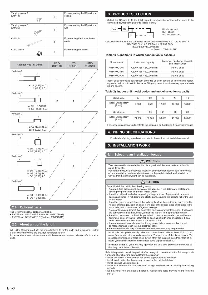
2.3. AccessoriesDo not discard the accessories required for installation until the installation work is complete.
Name and shape Q’ty ApplicationInstallation Manual
1
This manual
Hanger
3
For suspending the RB unit from ceiling
Washer6
For suspending the RB unit from ceiling
9366249030-03_IM.indb Sec1:29366249030-03_IM.indb Sec1:2 9/6/2013 6:26:05 PM9/6/2013 6:26:05 PM
En-3
Tapping screw A (Ø4×10)
6
For suspending the RB unit from ceiling
Tapping screw B (Ø4×25)
4
For suspending the RB unit from wall
Cable tie2
For mounting the transmission cable
Cable clamp1
For mounting the cable
Reducer type [in. (mm)] UTP-RU01AH
UTP-RU01BH
UTP-RU01CH
Reducer-Aa b
a: 3/8 (9.52) [O.D.]b: 1/2 (12.7) [I.D.]
4
Reducer-Ba b
a: 1/2 (12.7) [O.D.]b: 5/8 (15.88) [I.D.]
2 1
Reducer-Ca b
a: 1/2 (12.7) [O.D.]b: 3/8 (9.52) [I.D.]
1
Reducer-Da b
a: 3/4 (19.05) [O.D.]b: 7/8 (22.22) [I.D.]
2
Reducer-Ea bс
a: 3/4 (19.05) [O.D.]b: 1/2 (12.7) [I.D.]c: 5/8 (15.88) [I.D.]
2
Reducer-Fa b
a: 3/4 (19.05) [O.D.]b: 5/8 (15.88) [I.D.]
1
2.4. Optional partsThe following optional parts are available.
EXTERNAL INPUT WIRE A (Part No. 9368777005)• EXTERNAL INPUT WIRE D (Part No. 9368779016)•
2.5. About unit of the lengthAll Fujitsu General products are manufactured to metric units and tolerances. United States customary units are provided for reference only.In cases where exact dimensions and tolerances are required, always refer to metric units.
3. PRODUCT SELECTIONSelect the RB unit to fit the total capacity and number of the indoor units to be • connected downstream. (Refer to Tables 1 and 2)
I.U.=Indoor unitRB=RB unitO.U.=Outdoor unit
O.U. RB
I.U. I.U.
Calculation example: If the connected indoor units model code is 07, 09, 12 and 18. Q1= 7,500 Btu/h + 9,500 Btu/h + 12,000 Btu/h +
18,000 Btu/h=47,000 Btu/h → Select “UTP-RU01BH”
Table 1) Conditions in which connection is possible
Model Name Indoor unit capacity Maximum number of connect-able indoor units
UTP-RU01AH 7,500 ≤ Q1 ≤ 27,000 Btu/h Up to 3 units
UTP-RU01BH 7,500 ≤ Q1 ≤ 60,000 Btu/h Up to 8 units
UTP-RU01CH 7,500 ≤ Q1 ≤ 96,000 Btu/h Up to 8 units
* Indoor units connected downstream of the RB unit can operate all in the same operat-ing mode. Indoor units within the same RB group cannot simultaneously operate heat-ing and cooling.
Table 2) Indoor unit model codes and model selection capacity
Model code 07 09 12 14 18
Indoor unit capacity [Btu/h] 7,500 9,500 12,000 14,000 18,000
Model code 24 30 36 48 60
Indoor unit capacity [Btu/h] 24,000 30,000 36,000 48,000 60,000
For connectable indoor units, refer to the catalogue or the Design & Technical manual.•
4. PIPING SPECIFICATIONSFor details of piping specifi cations, refer to the outdoor unit installation manual.
5. INSTALLATION WORK
5.1. Selecting an installation location
WARNINGTake into consideration whether the place you install the main unit can fully with-stand its weight.For hanger bolts, use embedded inserts or embedded foundation bolts in the case of new installation, and use a hole-in-anchor if already installed, and attach in a way so that the unit’s weight can be supported.
CAUTIONDo not install this unit in the following areas:
Area with high salt content, such as at the seaside. It will deteriorate metal parts, • causing the parts to fail or the unit to leak water.Area fi lled with mineral oil or containing a large amount of splashed oil or steam, • such as a kitchen. It will deteriorate plastic parts, causing the parts to fail or the unit to leak water.Area that generates substances that adversely affect the equipment, such as sulfu-• ric gas, chlorine gas, acid, or alkali. It will cause the copper pipes and brazed joints to corrode, which can cause refrigerant leakage.Area containing equipment that generates electromagnetic interference. It will cause • the control system to malfunction, preventing the unit from operating normally.Area that can cause combustible gas to leak, contains suspended carbon fi bers or • fl ammable dust, or volatile infl ammables such as paint thinner or gasoline. If gas leaks and settles around the unit, it can cause a fi re.Area where small animals may live. It may cause failure, smoke or fi re if small • animals enter and touch internal electrical parts.Area where animals may urinate on the unit or ammonia may be generated.•
Install this unit, power supply cable and transmission cable at least 40 in. (1 m) away from a television or radio receivers. The purpose of this is to prevent TV reception interference or radio noise. (Even if they are installed more than 40 in. (1 m) apart, you could still receive noise under some signal conditions.)
If children under 10 years old may approach the unit, take preventive measures so that they cannot reach the unit.
Select the place to install the product after taking into consideration the following condi-tions, and after obtaining approval from the customer.
Install this unit in a location that has strong support and no vibrations.• Install in a location that has enough space for this unit installation.• Install in a well-ventilated area.• Install in a location that is not exposed to high temperatures or humidity over a long • periods.Do not install the unit near a bedroom. Refrigerant noise may be heard from the • piping.
9366249030-03_IM.indb Sec1:39366249030-03_IM.indb Sec1:3 9/6/2013 6:26:06 PM9/6/2013 6:26:06 PM

En-4
5.2. Installation dimensionsThe RB unit can be installed onto the wall or hanging from the ceiling.• Provide a service access for maintenance and inspection purposes as shown in the • fi gure below. Be sure to prepare service access in control box side.It is not necessary to provide drainage for this unit.• Install the RB unit without slant. (within ±2 °)• Use M8 or M10 for the hanger bolt size when hanging.•
Gas pipe
Suction gas pipe
Discharge gas pipe
UPWARD
A
B
C
5.2.1. Ceiling hanging Be sure to install so that the top side faces up.
13-1/8 (333)
11/16 (18)
(22)
7/8
(14
7)5-
13/1
6
(172)6-3/4 11-3/4 (298)
(147)5-13/16
(89)
3-1/
2
(198)7-13/16(155)6-1/8
4-7/
8 (1
24)
(206)8-1/8
1-7/
8 (4
8)2-
15/1
6 (7
5)7-
13/1
6 (1
98)
10-9
/16
(268
)
(30)1-3/16
15-3/4 (400)
15-3
/4 (4
00)
3-15/16 (100)
Unit: in. (mm)
(Top side)
Indoor unit side Outdoor unit side
Unit: in. (mm)
service access
Service accessIndoor unit side Outdoor unit side
Product mass [lbs. (kg)]UTP-RU01AH 15 (7)UTP-RU01BH 17 (7.5)UTP-RU01CH 18 (8)
A
A
B
B
C
C
20 (500) or more
20 (500) or more
1 (20) or more
1 (20) or more
Ceiling hanging
Installation limit Unit: in. (mm)
5.2.2. Wall hanging
13-1/8 (333)11/16 (18)
9/1
6 (1
5)
7-13/1
6 (19
8)10
-9/1
6 (2
68)
(198)7-13/16
(7)1/4
Unit: in. (mm)
service space
grille
1 (20) or more
Installation limit
1 (20) or more
12 (300) or more
E.g.: If installing a duct model vertically.
Unit: in. (mm)
5.3. Hanger bolt installation
WARNINGTake into consideration whether the place you install the main unit can fully withstand its weight, and, if necessary, install a hanger bolt after reinforcing with a beam.
Use a M8 or M10 size hanger bolt.
5.4. Hanging metal fi xturesSupport the connected piping within 40 in. (1 m) in front of and behind the main unit
using hanging metal fi xtures, as shown in the following diagram. If you place excessive weight on the main units hanging metal fi xture, the unit may fall off.
5.5. Installing the hanger
Hanger ×3 (accessories)Tapping screw A ×6
(accessories)
Mount the hanger (accessories).(1) If hung from the ceiling
9366249030-03_IM.indb Sec1:49366249030-03_IM.indb Sec1:4 9/6/2013 6:26:07 PM9/6/2013 6:26:07 PM
En-5
Hanger × 2 (accessories)
Tapping screw A × 4 (accessories)
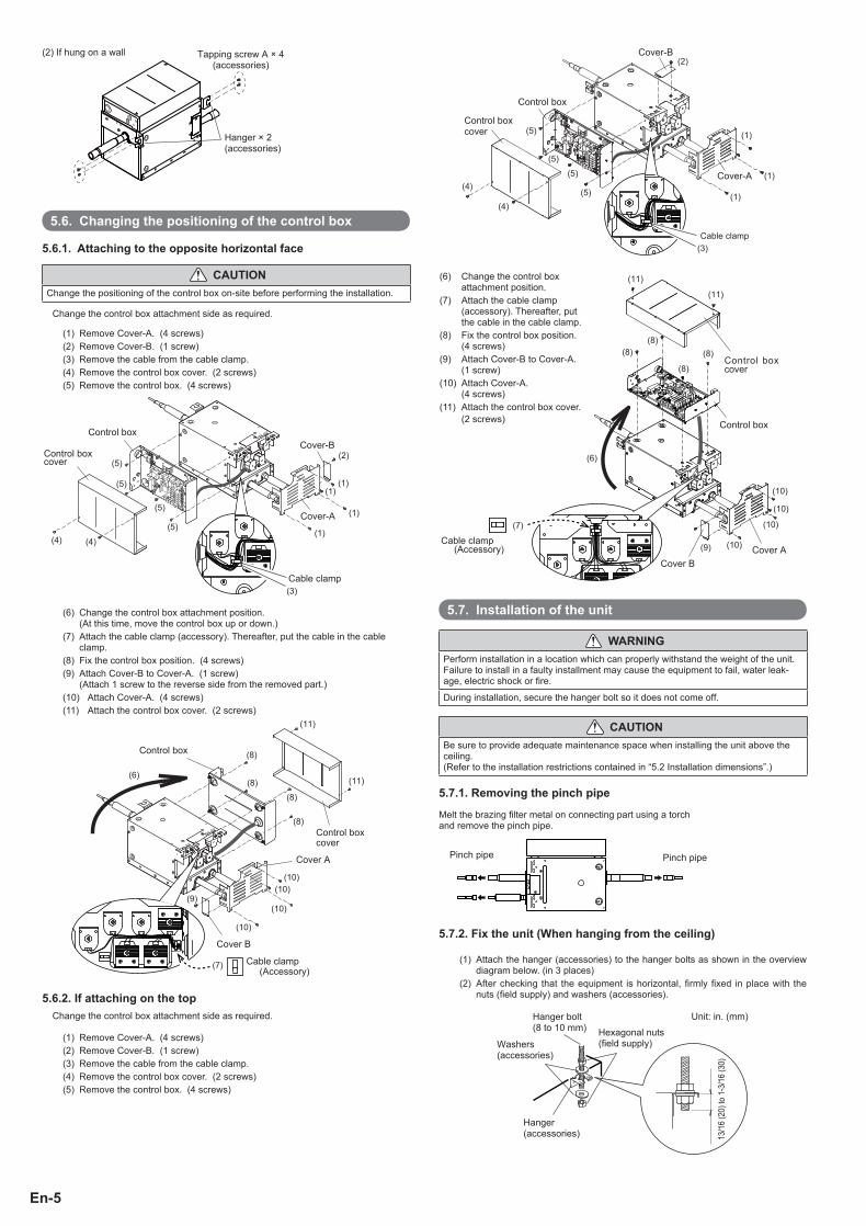
(2) If hung on a wall
5.6. Changing the positioning of the control box
5.6.1. Attaching to the opposite horizontal face
CAUTIONChange the positioning of the control box on-site before performing the installation.
Change the control box attachment side as required.
(1) Remove Cover-A. (4 screws)(2) Remove Cover-B. (1 screw)(3) Remove the cable from the cable clamp.(4) Remove the control box cover. (2 screws)(5) Remove the control box. (4 screws)
(1)
(1)
(5)
(5)
(5)
(2)
(1)(1)
(5)
(4) (4)
(3)
Cover-B
Cover-A
Control box
Control box cover
Cable clamp
(6) Change the control box attachment position. (At this time, move the control box up or down.)
(7) Attach the cable clamp (accessory). Thereafter, put the cable in the cable clamp.
(8) Fix the control box position. (4 screws)(9) Attach Cover-B to Cover-A. (1 screw)
(Attach 1 screw to the reverse side from the removed part.)(10) Attach Cover-A. (4 screws)(11) Attach the control box cover. (2 screws)
(8)
(8)
(8)
(6)
(8)
(9)(10)
(10)(10)
(10)
(11)
(11)
(7) Cable clamp (Accessory)
Control box cover
Cover B
Cover A
Control box
5.6.2. If attaching on the topChange the control box attachment side as required.
(1) Remove Cover-A. (4 screws)(2) Remove Cover-B. (1 screw)(3) Remove the cable from the cable clamp.(4) Remove the control box cover. (2 screws)(5) Remove the control box. (4 screws)
(1)
(1)
(1)
(2)
(4)
(4)
(5)
(5)
(5)
(5)
(3)
Cover-B
Cover-A
Control box
Control box cover
Cable clamp
(6)
(8)
(9) (10)
(11)
(11)
(8)(8)
(10)
(10)
(10)
(8)
(7)
Cable clamp (Accessory)
Cover BCover A
Control box
Control box cover
(6) Change the control box attachment position.
(7) Attach the cable clamp (accessory). Thereafter, put the cable in the cable clamp.
(8) Fix the control box position. (4 screws)
(9) Attach Cover-B to Cover-A. (1 screw)
(10) Attach Cover-A. (4 screws)
(11) Attach the control box cover. (2 screws)
5.7. Installation of the unit
WARNINGPerform installation in a location which can properly withstand the weight of the unit.Failure to install in a faulty installment may cause the equipment to fail, water leak-age, electric shock or fi re.
During installation, secure the hanger bolt so it does not come off.
CAUTIONBe sure to provide adequate maintenance space when installing the unit above the ceiling.(Refer to the installation restrictions contained in “5.2 Installation dimensions”.)
5.7.1. Removing the pinch pipe
Melt the brazing fi lter metal on connecting part using a torch and remove the pinch pipe.
Pinch pipe Pinch pipe
5.7.2. Fix the unit (When hanging from the ceiling)
(1) Attach the hanger (accessories) to the hanger bolts as shown in the overview diagram below. (in 3 places)
(2) After checking that the equipment is horizontal, fi rmly fi xed in place with the nuts (fi eld supply) and washers (accessories).
Hanger bolt (8 to 10 mm) Hexagonal nuts
(fi eld supply)
Hanger (accessories)
Washers (accessories)
13/1
6 (2
0) to
1-3
/16
(30)
Unit: in. (mm)
9366249030-03_IM.indb Sec1:59366249030-03_IM.indb Sec1:5 9/6/2013 6:26:09 PM9/6/2013 6:26:09 PM

En-6
5.7.3. Fix the unit (When hanging on the wall)Use the tapping screw B (accessories) to set up this unit.
6. PIPE INSTALLATION
6.1. Pipe selectionSelect the pipe to connect to the RB unit.•
Connection example 1
Outdoor unit
Indoor unit
(Liquid pipe)
Discharge gas pipe
Gas pipeRB
unitSuction gas pipe
Select the connection pipe from Table 2, below, based on the capacity of the indoor unit connected downstream.
Connection example 2
Outdoor unit
Indoor unit
Indoor unit
(Liquid pipe)
Select the connection pipe from Table 3, below, based on the total capacity of the indoor unit connected downstream.
Discharge gas pipe
RB
unitSuction gas pipe
Gas pipe
If the size of the selected pipe is different from the RB unit pipe size, use reducers • (accessories) to make the diameters match.
RB unit Gas pipe
Discharge gas pipe
Suction gas pipe
Reducer Reducer
Install the liquid pipe after referring to the outdoor unit installation manual for its diameter.
(1) UTP-RU01AH
Table 1) RB unit pipe size
Suction gas pipe [in. (mm)]
Discharge gas pipe [in. (mm)]
Gas pipe [in. (mm)]
1/2 (12.7) 3/8 (9.52) 1/2 (12.7)
Table 2) Connection pipe selection for when only 1 indoor unit is connected.
Indoor unit capacity [Btu/h]
Suction gas pipe [in. (mm)]
Discharge gas pipe [in. (mm)]
Gas pipe [in. (mm)]
7,500 9,500 12,000 14,000 1/2 (12.7) 3/8 (9.52) 1/2 (12.7)
18,000 24,000 5/8 (15.88)+Reducer
1/2 (12.7)+Reducer
5/8 (15.88)+Reducer
Table 3) Connection pipe selection for when 2 to 3 indoor units are connected.
Total capacity of indoor unit
[Btu/h]
Suction gas pipe [in. (mm)]
Discharge gas pipe [in. (mm)]
Gas pipe [in. (mm)]
15,000 ≤ x < 27,000 5/8 (15.88)+Reducer
1/2 (12.7)+Reducer
5/8 (15.88)+Reducer
(2) UTP-RU01BHTable 1) RB unit pipe size
Suction gas pipe [in. (mm)]
Discharge gas pipe [in. (mm)]
Gas pipe [in. (mm)]
3/4 (19.05) 1/2 (12.7) 3/4 (19.05)
Table 2) Connection pipe selection for when only 1 indoor unit is connected.
Indoor unit capacity [Btu/h]
Suction gas pipe [in. (mm)]
Discharge gas pipe [in. (mm)]
Gas pipe [in. (mm)]
7,500 9,500 12,000 14,000
1/2 (12.7)+Reducer
3/8 (9.52)+Reducer
1/2 (12.7)+Reducer
18,000 24,000 30,000
5/8 (15.88)+Reducer 1/2 (12.7) 5/8 (15.88)
+Reducer
36,000 48,000 3/4 (19.05) 1/2 (12.7) 3/4 (19.05)
60,000 3/4 (19.05) 5/8 (15.88)+Reducer 3/4 (19.05)
Table 3) Connection pipe selection for when 2 to 8 indoor units are connected.
Total capacity of indoor unit
[Btu/h]
Suction gas pipe [in. (mm)]
Discharge gas pipe [in. (mm)]
Gas pipe [in. (mm)]
15,000 ≤ x < 36,000 5/8 (15.88)+Reducer 1/2 (12.7) 5/8 (15.88)
+Reducer
36,000 ≤ x < 48,000 3/4 (19.05) 1/2 (12.7) 3/4 (19.05)
48,000 ≤ x < 60,000 7/8 (22.22)+Reducer
5/8 (15.88)+Reducer
7/8 (22.22)+Reducer
(3) UTP-RU01CHTable 1) RB unit pipe size
Suction gas pipe [in. (mm)]
Discharge gas pipe [in. (mm)]
Gas pipe [in. (mm)]
7/8 (22.22) 3/4 (19.05) 7/8 (22.22)
Table 3) Connection pipe selection for when 2 to 8 indoor units are connected.
Total capacity of indoor unit
[Btu/h]
Suction gas pipe [in. (mm)]
Discharge gas pipe [in. (mm)]
Gas pipe [in. (mm)]
60,000 ≤ x < 72,000 7/8 (22.22) 5/8 (15.88)+Reducer 7/8 (22.22)
72,000 ≤ x < 96,000 7/8 (22.22) 3/4 (19.05) 7/8 (22.22)
(4) Indoor unit model codes and capacityTable 4) Indoor unit model codes and model selection capacity
Model code 07 09 12 14 18
Indoor unit capacity [Btu/h] 7,500 9,500 12,000 14,000 18,000
Model code 24 30 36 48 60
Indoor unit capacity [Btu/h] 24,000 30,000 36,000 48,000 60,000
6.2. Selecting the pipe material
Copper pipesIt is necessary to use seamless copper pipes and it is desirable that the amount of residual oil is less than 0.04 oz./100 ft. (40 mg/10 m). Do not use copper pipes having a collapsed, deformed or discolored portion (especially on the interior surface). Other-wise, the expansion valve or capillary tube may become blocked with contaminants.As an air conditioner using R410A incurs pressure higher than when using conventional refrigerant (R22), it is necessary to choose adequate materials.Thicknesses of copper pipes used with R410A are as shown in the table. Never use copper pipes thinner than that in the table even when it is available on the market.
9366249030-03_IM.indb Sec1:69366249030-03_IM.indb Sec1:6 9/6/2013 6:26:12 PM9/6/2013 6:26:12 PM
En-7
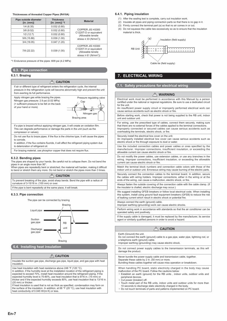
Thicknesses of Annealed Copper Pipes (R410A)
Pipe outside diameter [in. (mm)]
Thickness [in. (mm)] *1 Material
1/4 (6.35) 0.032 (0.80)COPPER JIS H3300
C1220T-O or equivalent(Allowable tensile
stress ≥ 33 (N/mm2))
3/8 (9.52) 0.032 (0.80)1/2 (12.7) 0.032 (0.80)
5/8 (15.88) 0.039 (1.00)3/4 (19.05) 0.047 (1.20)
7/8 (22.22) 0.039 (1.00)
COPPER JIS H3300 C1220T-H or equivalent
(Allowable tensile stress ≥ 61 (N/mm2))
*1 Endurance pressure of the pipes :609 psi (4.2 MPa)
6.3. Pipe connection6.3.1. Brazing
CAUTIONIf air or different type of refrigerant enters the refrigeration cycle, the internal pressure in the refrigeration cycle will become abnormally high and prevent the unit from exerting its full performance.
Apply nitrogen gas while brazing the pipes. Nitrogen gas pressure: 2.9 psi (0.02 MPa)(= suffi cient pressure to be felt on the back of your hand or more)
Pressure regulating valve
Brazing area
Nitrogen gas
Cap
If a pipe is brazed without applying nitrogen gas, it will create an oxidation fi lm.This can degrade performance or damage the parts in the unit (such as the compressor or valves).
Do not use fl ux to braze pipes. If the fl ux is the chlorine type, it will cause the pipes to corrode.In addition, if the fl ux contains fl uoride, it will affect the refrigerant piping system due to deterioration of refrigerant oil.
For brazing material, use phosphor copper that does not require fl ux.
6.3.2. Bending pipesThe pipes are shaped by your hands. Be careful not to collapse them. Do not bend the pipes in an angle more than 90°.When pipes are repeatedly bent or stretched, the material will harden, making it diffi cult to bend or stretch them any more. Do not bend or stretch the pipes more than 3 times.
CAUTIONTo prevent breaking of the pipe, avoid sharp bends. Bend the pipe with a radius of curvature of 3-15/16 in. (100 mm) or over.
If the pipe is bent repeatedly at the same place, it will break.
6.3.3. Pipe connection
Liquid pipe
Discharge gas pipe
unit
RBSuction gas pipe
The pipe can be connected by brazing
Brazing
Brazing
RB
unit
6.4. Installing heat insulation
CAUTIONInsulate the suction gas pipe, discharge gas pipe, liquid pipe, and gas pipe with heat insulation.
Use heat insulation with heat resistance above 248 °F (120 °C).In addition, if the humidity level at the installation location of the refrigerant piping is expected to exceed 70%, install heat insulation around the refrigerant piping. If the expected humidity level is 70-80%, use heat insulation that is 9/16 in. (15 mm) or thicker and if the expected humidity exceeds 80%, use heat insulation that is 13/16 in. (20 mm) or thicker.If heat insulation is used that is not as thick as specifi ed, condensation may form on the surface of the insulation. In addition, at 68 °F (20 °C), use heat insulation with heat conductivity of 0.045 W/(m·K) or less.
6.4.1. Piping insulation(1) After the sealing test is complete, carry out insulation work.(2) Insulate all pipes and piping connection parts so that there is no gap in it.(3) Firmly connect the terminal part (a) so that no air comes in or out.(4) Do not squeeze the cable ties excessively so as to ensure that the insulation
material is thick.
(a) Insulation (fi eld supply)
Cable tie (fi eld supply)
RB Unit
7. ELECTRICAL WIRING
7.1. Safety precautions for electrical wiring
WARNINGElectrical work must be performed in accordance with this Manual by a person certifi ed under the national or regional regulations. Be sure to use a dedicated circuit for the unit. An insufficient power supply circuit or improperly performed electrical work can cause serious accidents such as electric shock or fi re.
Before starting work, check that power is not being supplied to the RB unit, indoor unit and outdoor unit.
For wiring, use the prescribed type of cables, connect them securely, making sure that there are no external forces of the cables applied to the terminal connections.Improperly connected or secured cables can cause serious accidents such as overheating the terminals, electric shock, or fi re.
Securely install the electrical box cover on the unit. An improperly installed electrical box cover can cause serious accidents such as electric shock or fi re through exposure to dust or water.
Use the included connection cables and power cables or ones specified by the manufacturer. Improper connections, insufficient insulation, or exceeding the allowable current can cause electric shock or fi re.
Do not modify the power cables, use extension cables, or use any branches in the wiring. Improper connections, insufficient insulation, or exceeding the allowable current can cause electric shock or fi re.
Match the terminal block numbers and connection cable colors with those of the indoor unit or outdoor unit. Erroneous wiring may cause burning of the electric parts.
Securely connect the connection cables to the terminal board. In addition, secure the cables with wiring holders. Improper connections, either in the wiring or at the ends of the wiring, can cause a malfunction, electric shock, or fi re.
Always fasten the outside covering of the connection cable with the cable clamp. (If the insulator is chafed, electric discharge may occur.)
We suggest installing GFEB breakers or follow local electrical code. When installing this system, install using ground fault equipment breakers (GFEB) to reduce the risk of leaking current which result in electric shock or potential fi re.
Always connect the earth (ground) cable.Improper earthing (grounding) work can cause electric shocks.
Perform wiring work in accordance with standards so that the air conditioner can be operated safely and positively.
If the supply cable is damaged, it must be replaced by the manufacturer, its service agent or similarly qualifi ed persons in order to avoid a hazard.
CAUTIONEarth (Ground) the unit. Do not connect the earth (ground) cable to a gas pipe, water pipe, lightning rod, or a telephone earth (ground) cable. Improper earthing (grounding) may cause electric shock.
Do not connect power supply cables to the transmission terminals, as this will damage the product.
Never bundle the power supply cable and transmission cable, together.Separate these cable by 2 in. (50 mm) or more.Bundling these cables together will cause miss operation or breakdown.
When handling PC board, static electricity charged in the body may cause malfunction of the PC board. Follow the cautions below:• Establish an earth (ground) for the RB units , indoor units, outdoor units and
peripheral devices.• Cut power (breaker) off.• Touch metal part of the RB units, indoor units and outdoor units for more than
10 seconds to discharge static electricity charged in the body.• Do not touch terminals of parts and patterns implemented on PC board.
9366249030-03_IM.indb Sec1:79366249030-03_IM.indb Sec1:7 9/6/2013 6:26:13 PM9/6/2013 6:26:13 PM
En-8
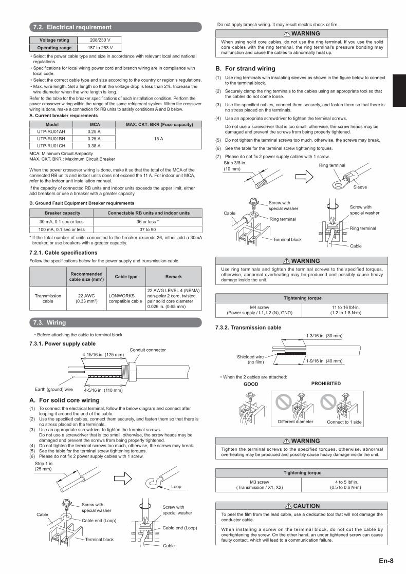
7.2. Electrical requirement
Voltage rating 208/230 V
Operating range 187 to 253 V
• Select the power cable type and size in accordance with relevant local and national regulations.
• Specifi cations for local wiring power cord and branch wiring are in compliance with local code.
• Select the correct cable type and size according to the country or region’s regulations.• Max. wire length: Set a length so that the voltage drop is less than 2%. Increase the
wire diameter when the wire length is long.Refer to the table for the breaker specifi cations of each installation condition. Perform the power crossover wiring within the range of the same refrigerant system. When the crossover wiring is done, make a connection for RB units to satisfy conditions A and B below.A. Current breaker requirements
Model MCA MAX. CKT. BKR (Fuse capacity)UTP-RU01AH 0.25 A
15 AUTP-RU01BH 0.25 AUTP-RU01CH 0.38 A
MCA: Minimum Circuit AmpacityMAX. CKT. BKR : Maximum Circuit Breaker
When the power crossover wiring is done, make it so that the total of the MCA of the connected RB units and indoor units does not exceed the 11 A. For indoor unit MCA, refer to the indoor unit installation manual.If the capacity of connected RB units and indoor units exceeds the upper limit, either add breakers or use a breaker with a greater capacity.
B. Ground Fault Equipment Breaker requirements
Breaker capacity Connectable RB units and indoor units
30 mA, 0.1 sec or less 36 or less *
100 mA, 0.1 sec or less 37 to 90
* If the total number of units connected to the breaker exceeds 36, either add a 30mA breaker, or use breakers with a greater capacity.
7.2.1. Cable specifi cationsFollow the specifi cations below for the power supply and transmission cable.
Recommended cable size (mm2) Cable type Remark
Transmission cable
22 AWG (0.33 mm²)
LONWORKS compatible cable
22 AWG LEVEL 4 (NEMA) non-polar 2 core, twisted pair solid core diameter 0.026 in. (0.65 mm)
7.3. Wiring
• Before attaching the cable to terminal block.
7.3.1. Power supply cableConduit connector
Earth (ground) wire 4-5/16 in. (110 mm)
4-15/16 in. (125 mm)
A. For solid core wiring(1) To connect the electrical terminal, follow the below diagram and connect after
looping it around the end of the cable. (2) Use the specifi ed cables, connect them securely, and fasten them so that there is
no stress placed on the terminals.(3) Use an appropriate screwdriver to tighten the terminal screws. Do not use a screwdriver that is too small, otherwise, the screw heads may be
damaged and prevent the screws from being properly tightened.(4) Do not tighten the terminal screws too much, otherwise, the screws may break.(5) See the table for the terminal screw tightening torques.(6) Please do not fi x 2 power supply cables with 1 screw.
Strip 1 in. (25 mm)
Screw with special washer
Screw with special washer
Cable end (Loop)Cable end (Loop)
Terminal blockCable
Loop
Cable
Do not apply branch wiring. It may result electric shock or fi re.
WARNINGWhen using solid core cables, do not use the ring terminal. If you use the solid core cables with the ring terminal, the ring terminal's pressure bonding may malfunction and cause the cables to abnormally heat up.
B. For strand wiring(1) Use ring terminals with insulating sleeves as shown in the fi gure below to connect
to the terminal block.
(2) Securely clamp the ring terminals to the cables using an appropriate tool so that the cables do not come loose.
(3) Use the specifi ed cables, connect them securely, and fasten them so that there is no stress placed on the terminals.
(4) Use an appropriate screwdriver to tighten the terminal screws.
Do not use a screwdriver that is too small, otherwise, the screw heads may be damaged and prevent the screws from being properly tightened.
(5) Do not tighten the terminal screws too much, otherwise, the screws may break.
(6) See the table for the terminal screw tightening torques.
(7) Please do not fi x 2 power supply cables with 1 screw.
Screw with special washer Screw with
special washer
Terminal block
Cable
Cable
Ring terminal
Ring terminal
Sleeve
Strip 3/8 in.(10 mm)
Ring terminal
WARNINGUse ring terminals and tighten the terminal screws to the specified torques, otherwise, abnormal overheating may be produced and possibly cause heavy damage inside the unit.
Tightening torque
M4 screw (Power supply / L1, L2 (N), GND)
11 to 16 lbf·in.(1.2 to 1.8 N·m)
7.3.2. Transmission cable
Shielded wire (no fi lm) 1-9/16 in. (40 mm)
1-3/16 in. (30 mm)
• When the 2 cables are attached:GOOD PROHIBITED
Different diameter Connect to 1 side
WARNINGTighten the terminal screws to the specified torques, otherwise, abnormal overheating may be produced and possibly cause heavy damage inside the unit.
Tightening torque
M3 screw (Transmission / X1, X2)
4 to 5 lbf·in.(0.5 to 0.6 N·m)
CAUTIONTo peel the fi lm from the lead cable, use a dedicated tool that will not damage the conductor cable.
When install ing a screw on the terminal block, do not cut the cable by overtightening the screw. On the other hand, an under tightened screw can cause faulty contact, which will lead to a communication failure.
9366249030-03_IM.indb Sec1:89366249030-03_IM.indb Sec1:8 9/6/2013 6:26:14 PM9/6/2013 6:26:14 PM
En-9
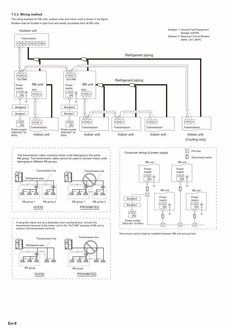
7.3.3. Wiring methodThe wiring example for RB units ,outdoor units and indoor units is shown in the fi gure. Breaker shall be located in sight from and readily accessible from all RB units.
L1 L2(N)
L1 L2(N)
L1 L2(N)
L1 L2(N)
Breaker2Breaker2
Breaker1Breaker1
Power supply
Power supply
Outdoor unit
Transmission
IN/U IN/U
RB unit RB unit
Indoor unit Indoor unit Indoor unit Indoor unit Indoor unit(Cooling only)
Refrigerant piping
Refrigerant piping
Power supply 208/230V 1 60Hz
Power supply 208/230V 1 60Hz
TransmissionTransmission Transmission Transmission Transmission
Breaker 1: Ground Fault Equipment Breaker (GFEB)
Breaker 2: Maximum Circuit Breaker (MAX. CKT. BKR)
Disconnect switch shall be installed between RB unit and pull box.
The transmission cable connects indoor units belonging to the same RB group. The transmission cable cannot be used to connect indoor units belonging to different RB groups.
GOOD PROHIBITED
Refrigerant pipe
RB group 1 RB group 1RB group 2 RB group 2
Transmission lineTransmission line
Crossover wiring of power supply
RB unit RB unit
: Disconnect switch
: Pull box
Power supply
Power supply
Power supplyBreaker2
Breaker1
Power supply 208/230V 1ø 60Hz
RB unit RB unit
Power supply
GOOD PROHIBITED
Transmission line
RB group RB group
Transmission line
Refrigerant pipe
If using the indoor unit as a dedicated room cooling device, connect the transmission terminal of the indoor unit to the "OUT/RB" terminal of RB unit or outdoor unit transmission terminal.
9366249030-03_IM.indb Sec1:99366249030-03_IM.indb Sec1:9 9/6/2013 6:26:15 PM9/6/2013 6:26:15 PM
En-10
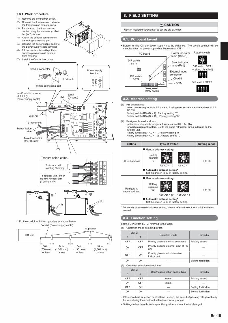
7.3.4. Work procedure(1)
(1)
(1)
Remove the control box cover.(2) Connect the transmission cable to
the transmission cable terminal.(3) Firmly attach the transmission
cables using the accessory cable tie. (in 2 places)
(4) Attach the conduit connector on the wiring connecting port.
(5) Connect the power supply cable to the power supply cable terminal.
(6) Fill the cable holes with putty in order to prevent small animals from entering.
(7) Install the Control box cover.
(5)
To indoor unit (cooling / heating)
Transmission cable
To indoor unit
Lock nut
Conduit connector Power supply terminal
Earth(Ground)
(4) Conduit connector (L1, L2 (N): Power supply cable)
Lock nut
Wiring connecting port
To outdoor unit / other RB unit
To outdoor unit / other RB unit / indoor unit (Cooling only)
Transmission calbe
(2)
(3)(6)
• Fix the conduit with the supporters as shown below.Conduit (Power supply cable)
Supporter
RB unit
30 in. (756 mm)
or less
54 in. (1,361 mm)
or less
54 in. (1,361 mm)
or less
54 in. (1,361 mm)
or less
8. FIELD SETTING
CAUTIONUse an insulated screwdriver to set the dip switches.
8.1. PC board layoutBefore turning ON the power supply, set the switches. (The switch settings will be • disabled after the power supply has been turned ON.)
PC board
DIP switch SET1
DIP switch SET1(setting disabled)
Rotary switch
External Input connector
Error indicator lamp (Red)
Power indicator lamp (Green)
CNA01CNA02 DIP switch SET2
Rotary switch
DIP switch SET2
8.2. Address setting(1) RB unit address
When connecting multiple RB units to 1 refrigerant system, set the address at RB AD SW.Rotary switch (RB AD × 1)...Factory setting “0”Rotary switch (RB AD × 10)...Factory setting “0”
(2) Refrigerant circuit addressIn the case of multiple refrigerant systems, set REF AD SWfor each refrigerant system. Set to the same refrigerant circuit address as the outdoor unit.Rotary switch (REF AD × 1)...Factory setting “0”Rotary switch (REF AD × 10)...Factory setting “0”
Setting Type of switch Setting range
RB unit address
Manual address setting
Setting example
“2”
RB AD × 10 RB AD × 1
Automatic address setting*Set this switch to 00 at factory setting.
0 to 63
Refrigerant circuit address
Manual address setting
Setting example
“63”
REF AD × 10 REF AD × 1
Automatic address setting*Set this switch to 00 at factory setting.
0 to 99
* For details of automatic address setting, please refer to the outdoor unit installation manual.
8.3. Function settingSet the DIP switch SET2, referring to the table.(1) Operation mode selecting switch
SET 2Operation mode Remarks
1 2
OFF OFF Priority given to the fi rst command Factory setting
ON OFF Priority given to external input of RB unit
OFF ON Priority given to administrative indoor unit
ON ON Setting forbidden
(2) Cool/heat selection control time
SET 2Cool/heat selection control time Remarks
3 4
OFF OFF 6 min Factory setting
ON OFF 3 min
OFF ON Setting forbidden
ON ON Setting forbidden
If the cool/heat selection control time is short, the sound of passing refrigerant may • be loud during the cool/heat selection control process.
Settings other than those in specified positions are not to be changed.•
9366249030-03_IM.indb Sec1:109366249030-03_IM.indb Sec1:10 9/6/2013 6:26:15 PM9/6/2013 6:26:15 PM

En-11
9. EXTERNAL INPUT
RB unit can be switched cooling priority and heating priority by using RB unit • PC board CNA01 or CNA02.
The "external input priority mode" must be set by changing DIP switch SET2-• 1,2 on PC board of RB unit.
A twisted pair cable (22AWG) should be used. Maximum length of cable is • 492 ft. (150 m).
Use an external input cable with appropriate external dimension, depending • on the number of cables to be installed.
The wire connection should be separate from the power cable line.•
INPUT SELECT
Use either one of these types of terminal according to the application. (Both types of terminals cannot be used simultaneously.
Dry contact terminal ([CNA01])
When a power supply is unnecessary at the input device you want to connect, use the Dry contact terminal ([CNA01]).
*a: Select very low current use contacts (usable at DC12V, DC1mA or less).
*b: The wiring is different from Apply voltage terminals. Be suffi ciently careful when wiring.
1
2
connected unit
PC Board
GND
*a
*b
CNA01
When connected to Dry contact terminals of multiple RB units with a connected unit, insulate each RB unit with relay, etc. as shown on below example.
RB
uni
tR
B u
nit
Pow
er s
uppl
y fo
r rel
ay
Input device
K1-K2 : Relay (Device for DC current)
PC board
PC board
K1
K2
CNA 01
CNA 01
NOTE : When connected to multiple RB units directly, it will cause breakdown.
Apply voltage terminal ([CNA02])
When a power supply must be provided at the input device you want to connect, use the Apply voltage terminal ([CNA02])
1
2
3
++-
-
Inpu
t dev
ice
Load resistance
*1DC power sup-ply 12 - 24V
connected unit
PC board
CNA02*c
*d
*1: Make the power supply DC12 to 24V. Select a power supply capacity with an ample surplus for the connected load.Do not impress a voltage exceeding 24V across pins 1-3.
*c: The allowable current is DC 5mA to 10mA. (Recommended: DC5mA) Provide a load resistance such that the current becomes DC10mA or less. Select very low current use contacts (usable at DC12V, DC1mA or less).
*d: The polarity is [+] for pin 1 and [-] for pin 3. Connect correctly.
When connected to Apply voltage terminals of multiple RB units with a connected unit, be sure to make a branch outside the RB unit using a pull box, etc. as shown on below example.
Inpu
t dev
ice
RB
uni
tR
B u
nit
Load resistance
DC power supply 12 - 24V
connected unit
PC board
PC board
CNA 02
CNA 02
COOLING/HEATING PRIORITY FUNCTION
"Edge" input only
Connector Input signal Command
CNA01 or CNA02OFF → ON Heating priority
ON → OFF Cooling priority
CNA01 or CNA02
Priority mode Heating
On
Off
Cooling
10. TEST RUN
10.1. Test run using Outdoor unit (PC board)
• Refer to the Installation Manual for the outdoor unit to perform the test run using the outdoor unit.
10.2. Test run using Remote Controller
• Refer to the Installation Manual for the remote controller to perform the test run using the remote controller.
11. CHECK LISTPay special attention to the check items below when installing the RB unit (s). After installation is complete, be sure to check the following check items again.
CHECK ITEMS If not performed correctly CHECK BOX
Has the RB unit been installed correctly?
Vibration, noise, RB unit may drop
Has there been a check for gas leaks (refrigerant pipes)? No cooling, No heating
Has heat insulation work been completed? Water leakage
Is the voltage of the power source the same as that indicated on the label on the RB unit?
No operation, heat or burn damage
Is the address setting correctly configured? No operation
Are the wires and pipes all connected completely?
No operation, heat or burn damage
Is the RB unit earthed (grounded)? Short circuit
Is the connection cable the specified thickness?
No operation, heat or burn damage
9366249030-03_IM.indb Sec1:119366249030-03_IM.indb Sec1:11 9/6/2013 6:26:18 PM9/6/2013 6:26:18 PM
En-12
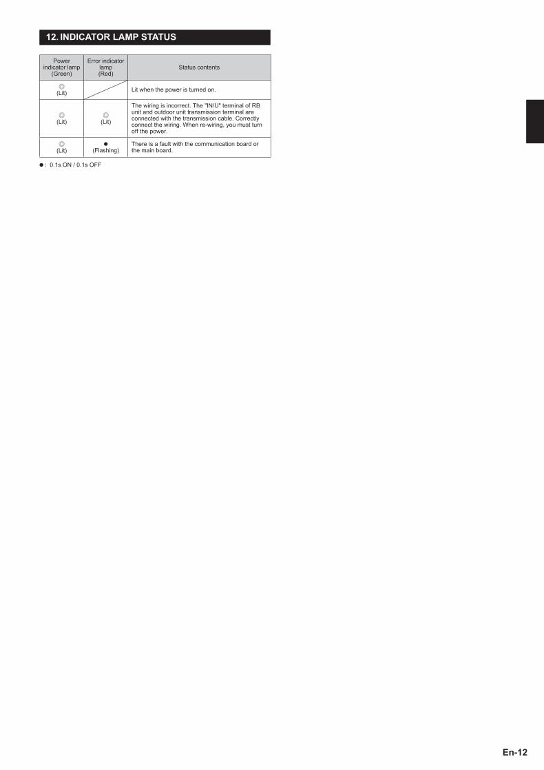
12. INDICATOR LAMP STATUS
Power indicator lamp
(Green)
Error indicator lamp (Red)
Status contents
(Lit) Lit when the power is turned on.
(Lit) (Lit)
The wiring is incorrect. The "IN/U" terminal of RB unit and outdoor unit transmission terminal are connected with the transmission cable. Correctly connect the wiring. When re-wiring, you must turn off the power.
(Lit)●
(Flashing)There is a fault with the communication board or the main board.
● : 0.1s ON / 0.1s OFF
9366249030-03_IM.indb Sec1:129366249030-03_IM.indb Sec1:12 9/6/2013 6:26:18 PM9/6/2013 6:26:18 PM