tm small duct heating, cooling and indoor air quality...
TRANSCRIPT

Manufactured By
Includes:PWM Design
PWM Installation ManualZone Controller Input Sheets
PWM (Pulse Width Modulation Zone Controller)
Design, Installation, and Operation
Module PWM - PWM Installation Manual 040111
TM
Small Duct Heating, Cooling andIndoor Air Quality Systems
www.hi-velocity.com


-2- © 1995-2009 Energy Saving Products Ltd.
Each basic layout has it’s typical applications. For example, the Perimeter Loop and Main Branch Layouts are best served doing multi-zones of 4 or more, with the Open Duct best servicing 2 - 4 zones. Perimeter Loop works well in a single level application, while the Main branch is better suited for multi-level applications.
The Main Plenum Branch method is similar to a Perimeter Loop, in that you direct the main plenum to the area loads, with branch tees directing each zone to the outlets, once again installing zone dampers.
Whichever method of zoning layout is utilized, it continues to be important for Indoor Air Quality that a certain amount of air is by-passed through each zone. This air recirculation is also important for Energy Efficiency, and even though the zone may not be calling for it, the recirc air will aid in overall living comfort.
In some installations, it is necessary to reduce the size of the main plenum. Caution must be used when reducing plenum size, since smaller ducts can handle less number of outlets. Also keep in mind that once reduced, the main
There are three basic layout styles to be used with the PWM controller: the Perimeter Loop/Branch (Fig. 01), the Main Plenum Branch (Fig. 02), and the Open Duct standard design (Fig. 03).
The Open Duct layout is the same concept that is used in the Hi-Velocity Design Manual. This method utilizes the branch split and bullhead tees planning of air flow, with each zone being individually controlled.
When designing the perimeter loop, first determine the system load and individual zones. Locate the Fan Coil and vent outlets as per the design manual. Design the Perimeter Loop with the proper diameter 8” or 10” duct, as determined by the fan coil unit. Use appropriate plenum duct size around the perimeter of the structure.
When sizing the branch zone plenum off the Perimeter Loop, use the Zoning Duct Reduction Guide (Table 01). Total the outlets for each individual zone to determine the zone plenum duct diameter. Locate the tee servicing this zone to minimize the zone plenum duct, and run the plenum where it’ll be possible to keep the AFD duct to 10’ and 15’ lengths. There is no minimum length on the Zone Main Plenum run. For maximum length allowed refer to the Zoning Duct Reduction Guide. (Table 01)The Perimeter Loop layout is as the term implies.
A perimeter loop of plenum duct is installed in the structure, from there branch tees are installed for each zone dependant on the zone size, and a zone damper is installed for each take-off/zone.
Pulse Width Modulation (PWM) Design & Installation Guide
The Main Plenum also requires that a comprehensive system load is completed, zones determined, fancoil and outlets located as per the design manual. The Plenum duct is then located to direct the air to the loads at each zone, and elbow and tees can be located where required, as per the design manual.
The zone duct diameter is determined from the duct reduction guide (Table 01) and an appropriate balanced tee installed. Locate the tee servicing this zone to minimize the zone plenum duct, and run the plenum where it’ll be possible to keep the AFD duct to 10’ and 15’ lengths. There is no minimum length on the Zone Main Plenum run. For maximum length allowed refer to the Zoning Duct Reduction Guide. (Table 01)
The Open Branch layout utilizes the Hi-Velocity Design Manual in its entirety, from Load calculation to duct location. This method is best suited when 2 - 4 zones are utilized, by following the design manual and duct reduction guide if necessary. You will either branch or bullhead the tees to 1 or 2 zones, and continue the plenum to the furthest run, installing zone dampers where required.
Module PWMPulse Width Modulation Zone Control (2/10)
Module PWM Pulse Width Modulation Zone Control (2/10)
The PWM is a pressure reactive Zone Controller that will change the energy input to maintain constant CFM flow of open outlets from 150 cfm to 1250 cfm, eliminating the need for by-pass dampers. The PWM controller has three independent settings for Cooling, Heating and Recirc. Fan, allowing for fine tuning with variable commands. The PWM unit is compatible with most forced air zoning packages and has been successfully integrated with Inverter Drive Heat Pump Condensing Units, providing leading edge technology for unsurpassed comfort and energy efficiency.
plenum cannot be increased again. The Branch Take Offs easily form to ducts in the 6” to 8” range; extra care must be taken with smaller sized ducts to ensure a proper air seal. For tee reductions, keep the tee to the full duct size, reducing only after the tee. Keep the length of the smaller duct sizes to a minimum, since the duct loss is much higher. If a hole saw will be used to drill the branch take-off holes, metal ducts are recommended to be 28 gauge steel.
2
Layout Design
Perimeter Loop (Fig. 01)
Main Plenum Branch (Fig. 02)
Open Duct System (Fig. 03)

-3- © 1995-2009 Energy Saving Products Ltd.
Fig. 01 - Perimeter Loop
Fig. 02 - Main Plenum Branch
LEGEND
Main PlenumBranch ZoneHE Outlet2” OutletHE and 2” Flex DuctZone Damper
Fig. 03 - Open Duct System
Module PWMPulse Width Modulation Zone Control (3/10)
Module PWM Pulse Width Modulation Zone Control (3/10)
Table 01 - Zoning Duct Reduction GuideDuct Size # of vents
(2”)# of vents
(HE)Plenum
Max. Length5” 6 3 40’6” 12 6 50’7” 19 9 60’8” 29 14 70’10” 50 25 100’
Pulse Width Modulation (PWM) Design Layouts
3

-4- © 1995-2009 Energy Saving Products Ltd.4
The location of the Pressure Tap is important for proper operation. Assure that it is located a minimum of 18” (457mm) downstream from the fancoil. 36” (914mm) downstream provides the most consistent reading, located before any dampers. If an elbow or tee is installed before the tap, then the tap must be a minimum of 18”(457mm) downstream from that point.
Begin by drilling a 3/4” (127mm) hole in the plenum at the desired point. (Fig. 05)
Assuring that the pressure tap is over the hole, Attach pressure tap with (8) 5/16” self tapping screws provided. (Fig. 06)
BE SURE TO READ ALL INSTRUCTIONS PRIOR TO BEGINNING INSTALLATION!
Fig. 05 - Drill 3/4” (13mm) hole
Quick acting, spring shut dampers are not to be used with the PWM control. Instead, it is suggested to use a slow acting electronic damper, which gives the PWM controller adequate time to adjust to variations in duct pressure.
Begin by removing the entire control assembly, the circuit board, motor control board, mounting system, etc.
Mount the new control assembly (Fig. 01) in the fan coil. The control assembly is held in place by the blower access hatch, so ensure that the screw holes are not covered by the edges of the assembly.
Reconnect the motor cable, power supply, and thermostat wiring.
Route both air lines to the exterior of the fan coil through one of the three holes located on the side of the fan coil, inserting the provided plastic grommet into the chosen hole before running air lines.(Fig. 03) Run air lines to the outside of the unit through the provided grommet. The air lines may be secured to the unit by the supplied plastic conduit straps. (Fig. 03) Ensure that there are no kinks in the air lines as this may hinder performance. The positive marked air line is to be connected to the Pressure Tap. The shorter air line, marked with a negative sign, is to be mounted on the exterior of the unit, to sense atmospheric pressure. Ensure that this line is mounted facing downwards to prevent any accumulation of debris. Do not block or restrict any air lines. (Fig. 04)
Fig. 02 - Port Markings
Fig. 01 - PWM Controller Assembly
Using the 1/4” tubing provided, connect the air lines to their designated ports on the PWM circuit box. The air lines provided are marked with a positive or negative sign. Each line is to be connected to it’s respective quick connect port on the outside of the PWM circuit box. These ports are marked with a matching positive or negative sign. (Fig. 02)
Fig. 03 - Air Lines
Fig. 04 - Air Lines
The PWM Controller is compatible with most Forced Air Zoning Packages. Zoning control panels with a Recirculation Fan Option are strongly recommended, so as to utilize continuous air circulation for optimal Indoor Air Quality (IAQ) and Energy Efficiency. Independent testing has shown that utilizing the recirculation fan with the Hi-Velocity Systems EPC motor reduces total energy usage. This is due to less on/off cycling of AC and Heating equipment by constant de-stratification of the air.
PWM Installation
Installing the PWM Zone Controller
Pressure Tap Location & Installation
Mounting the Pressure Tap
Module PWMPulse Width Modulation Zone Control (4/10)
Module PWM Pulse Width Modulation Zone Control (4/10)

-5- © 1995-2009 Energy Saving Products Ltd.5
To set the PWM Controller, the required airflow capacity must be determined for each operating mode. The required CFM/Ton (l/s per kW) is 250 (34), 200 (27), and 125(17) for Cooling, Heating and Recirculation Fan respectively. Divide the total CFM required for each fan speed by the total number of outlets. Keep in mind that each HE outlet represents 2 standard outlets. This will provide the average CFM per outlet.
With the PWM module hooked into the circuit board, control board and the duct work, you can go about adjusting the trimpots to your desired performance. Make sure everything internally to the unit is reconnected.
For full and proper tuning of the PWM controller, repeat the above process for heating and recirculation fan.
When tuning is complete, cycle all zone dampers to verify total system operation.
With the basic programming set, you are now ready to fine tune the PWM Controller. With the power on, all zone dampers opened, and the cooling energized, allow the fan 2 minutes to fully ramp up. Once the fan is fully ramped up, read and record airflow readings from all of the outlets. Total the cfm output of all outlets, and divide that number by the total number of outlets, to find the mean average. Keep in mind that each HE outlet represents 2 standard outlets. Select one outlet that is representative of this average, and use that outlet as a base reference for further adjustment. Increase or decrease the trim pot to obtain the ideal average cfm, using the average outlet as a tuning guide. Finally, once again read and record total airflow for cooling mode, to assure proper total cfm.
- Using a controls screwdriver, adjust the appropriate trim pot. (Cooling, Heating, or Recirculation Fan) A clockwise turn will increase the airflow output, while a counter-clockwise turn will decrease the airflow. Be sure to take note of the red LED light present on the PWM controller.
Recirculation FanHeating
(W2 terminal)
Cooling (Y2 Terminal)
- Ensure air lines are correctly mounted and secured
- Power Unit
- Ensure all zones and outlets are open
- Energize the thermostat setting to be adjusted. (Cooling, Heating, or Recirculation Fan)
Fig. 07 - Quick Connect
Fig. 06 - Attach pressure tap
Connect the positive air line to the quick connect fitting on the pressure tap. This line is to be connected at the opposite end to the PWM Controller through the positive fitting. (Fig 07)
- When the PWM controller has reached the set point and is operating within an acceptable range, the red LED light on the PWM controller will flicker sporadically on and off to show that it is properly sensing pressure in the system.
- Be sure to wait 45 seconds between adjustments to allow the PWM controller to reach and maintain the set point.
- If the light on the PWM controller remains either off or on after 45 seconds, the current set point is outside the normal operating range and must be adjusted accordingly:
* No light indicates that the trim pot is above normal operating range and should be decreased (counter-clockwise).
* A solid light indicates that the trimpot is below normal operating range and should be increased (clockwise).
- When all trim pots have been adjusted to normal operating conditions, fine tuning of the PWM controller may commence.
Setting the PWM Device
Basic Programming
Fine Tuning the PWM Controller
Module PWMPulse Width Modulation Zone Control (5/10)
Module PWM Pulse Width Modulation Zone Control (5/10)

-6- © 1995-2009 Energy Saving Products Ltd.6
• Initial programming of the PWM Controller for cooling, heating and recirculation fan must be done with all dampers in the open position, to verify maximum load capacities.
• To find outlet CFM: Multiply Knots by 2.2 for 2”, and by 4.2 for HE Multiply FPM by 0.022 for 2” and by 0.042 for HE
• As the PWM controller takes up to 45 seconds to adjust to changes in duct pressure, the use of slow acting electronic dampers is suggested for proper operation of the PWM controller. Fast acting spring return dampers are not to be used.
• To find outlet L/s: Multiply Knots by 1.4 for 2”, and by 1.98 for HE Multiply m/s by 2.02 for 2” and by 3.85 for HE
Important Notes
Wiring the PWM Controller
Module PWMPulse Width Modulation Zone Control (6/10)
Module PWM Pulse Width Modulation Zone Control (6/10)
PWM CONTROL BOARD
PWM CIRCUIT BOXEPC CIRCUIT BOARD

-7- © 1995-2009 Energy Saving Products Ltd.7
5 MINUTE
TIMER
24HON
OFF
Z1C
H1 X2 X1C
W1 W2 C R Y2 Y1 D O/BG
AUXILIARY RELAY(HEATING)
A3
A2
A1
L
N
N N L L
N L L
R
N
N
F1
24vNeu
tral
Gro
un
d
115v
/230
vL
INE
INL
ive
BK WH G
Red
Wire
EPC CIRCUIT BOARD
24v / 20vaTRANSFORMER
POWER CABLE
CONTROLLERCABLE
EQUIPMENTGROUND G
87
64
32
15
ON
*S
EE
NO
TE
S
WARNING: HIGH VOLTAGE
ALLOW 5 MINUTES AFTER DISCONNECTING POWERFROM THE DRIVE BEFORE DISCONNECTING THE MOTOR.
THIS DEVICE CONTAINS CAPACITORS WHICH STOREPOTENTIALLY DANGEROUS AMOUNTS OF ENERGY.
AVERTISSEMENT: HAUT VOLTAGECET APPAREIL EST MUNI DE
CONDENSATEURS QUI EMMAGASINENT UN MONTANTD’ÉNERGIE POTENTIELLEMENT DANGEREUX.
AVANT DE DÉCONNECTER LE MOTEUR, ATTENDRE5 MINUTES APRÈS AVOIR DÉBRANCHÉ L’ALIMENTATION
ÉLECTRIQUE DE LA DRIVE.
MO
TO
R
R BW B
MOTOR CABLE
PWM CONTROL BOARD
RC
1Y2
1W2
G
J1
L1
J2
U2
PWM CIRCUIT BOX
Cool
Heat
Fan
PWM INTERFACECABLE
WG
318.
01P
cbw
-001
sep
-035
HE PWM WIRING
MAR.16
HE Fan Coil - PWM Wiring DiagramUSE W2 & Y2 FOR HEATING AND COOLING TERMINALS
N - neutral L - line voltageA1 - auxiliary normally openA2 - auxiliary normally closedA3 - auxiliary common
X1 - freeze stat terminalX2 - freeze stat terminalH1 - condensing unit 24v output C - condensing unit 24 vac commonZ1 - heating mode 24v output C - 24 vac common
1) USE THERMOSTAT FAN SWITCH TO DISABLE/ENABLE CONTINUOUS FAN.2) ‘C’ TERMINAL ON THERMOSTAT (COMMON) IS NOT
NEEDED FOR SOME THERMOSTATS. CONSULT THERMOSTAT INSTRUCTIONS FOR DETAILS.3) A3 (AUXILIARY RELAY COMMON) CAN BE USED WITH A1 AND/
OR A2 AS DRY CONTACTS, ARMED 24v FROM THE ‘R’ TERMINAL, OR ARMED FROM THE ‘L’ TERMINAL.
CAUTIONdisconnect the electric poWer Before servicing
ATTENTIONdecconnecter du circuitd’alimentation electriQue
avant l’entre-tien
4) AUXILIARY RELAY TIMER ACTIVATES CIRCUIT FOR 5 MINUTES EVERY 24 HOURS STARTING WHEN POWER IS APPLIED TO THE UNIT. RED LIGHT IS ON WHEN AUXILIARY RELAY IS ACTIVATED.5) SEE INSTALLATION MANUAL FOR MORE DETAILED WIRING
DIAGRAMS AND DIP SWITCH SETTINGS.6) FAILURE TO READ AND FOLLOW ALL INSTRUCTIONS
CAREFULLY BEFORE INSTALLATION COULD CAUSE PERSONAL INJURY AND/OR PROPERTY DAMAGE.
NOTES:
DIP SETTINGS ARE REMOVED FROM THE PROGRAMMING OF THE PWM CONTROL BOARD
BWGBRW
Pcbw
-001
sep-
036
Module PWMPulse Width Modulation Zone Control (7/10)
Module PWM Pulse Width Modulation Zone Control (7/10)

-8- © 1995-2009 Energy Saving Products Ltd.
#Location
IdealCFM
InitialFPM/CFM
Prgm’dFPM/CFM
#Location
IdealCFM
InitialFPM/CFM
Prgm’dFPM/CFM
1 262 273 284 295 306 317 328 339 3410 3511 3612 3713 3814 3915 4016 4117 4218 4319 4420 4521 4622 4723 4824 4925 50
TOTALS:
AVERAGE: (TOTAL # OF VENTS DIVIDED BY # OF LOCATIONS)
MODEL: _______________________
# OF OUTLETS: _________________
IDEAL CFM TOTAL: ________________
PROGRAMMED CFM TOTAL: ________
8
PWM Controller Input Sheets (heating)
Module PWMPulse Width Modulation Zone Control (8/10)
Module PWM Pulse Width Modulation Zone Control (8/10)

-9- © 1995-2009 Energy Saving Products Ltd.9
#Location
IdealCFM
InitialFPM/CFM
Prgm’dFPM/CFM
#Location
IdealCFM
InitialFPM/CFM
Prgm’dFPM/CFM
1 262 273 284 295 306 317 328 339 3410 3511 3612 3713 3814 3915 4016 4117 4218 4319 4420 4521 4622 4723 4824 4925 50
TOTALS:
AVERAGE: (TOTAL # OF VENTS DIVIDED BY # OF LOCATIONS)
MODEL: _______________________
# OF OUTLETS: _________________
IDEAL CFM TOTAL: ________________
PROGRAMMED CFM TOTAL: ________
PWM Controller Input Sheets (cooling)
Module PWMPulse Width Modulation Zone Control (9/10)
Module PWM Pulse Width Modulation Zone Control (9/10)
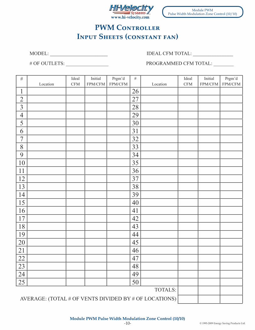
-10- © 1995-2009 Energy Saving Products Ltd.10
#Location
IdealCFM
InitialFPM/CFM
Prgm’dFPM/CFM
#Location
IdealCFM
InitialFPM/CFM
Prgm’dFPM/CFM
1 262 273 284 295 306 317 328 339 3410 3511 3612 3713 3814 3915 4016 4117 4218 4319 4420 4521 4622 4723 4824 4925 50
TOTALS:
AVERAGE: (TOTAL # OF VENTS DIVIDED BY # OF LOCATIONS)
MODEL: _______________________
# OF OUTLETS: _________________
IDEAL CFM TOTAL: ________________
PROGRAMMED CFM TOTAL: ________
PWM Controller Input Sheets (constant fan)
Module PWMPulse Width Modulation Zone Control (10/10)
Module PWM Pulse Width Modulation Zone Control (10/10)

Energy Saving Products Ltd., established in 1983, manufactures the Hi-Velocity SystemsTM product line for residential, commercial and multi-family markets. Our facilities house Administration, Sales, Design, Manufacturing, as well as Research & Development complete with an in-house test lab. Energy Saving Products prides itself on Customer Service and provides design services and contractor support.
For all of your Heating, Cooling and Indoor Air Quality needs, the Hi-Velocity System is the right choice for you!
Phone: 780-453-2093 Fax: 780-453-1932
Toll Free: 1-888-652-2219HARDI
www.hi–velocity.com
Hi-Velocity HE Fan Coils, Green TechnologyBuild Smart, Breathe Easy
Small Duct Heating, Cooling and IAQ Systems