tm studio (lite) instruction · 10/23/2018 · tm studio lite instruction sw version: 1.06.1200...
TRANSCRIPT
TM Studio Lite Instruction SW Version: 1.06.1200 Document Version: 1.00 i
SW Version: 1.06.1200
Document version:1.00
Release Date: 2018-10-23
TM Studio (Lite)
Instruction

TM Studio Lite Instruction SW Version: 1.06.1200 Document Version: 1.00 2
This Manual contains information of the Techman Robot product series (hereinafter referred to as the TM
Robot). The information contained herein is the property of Techman Robot Corporation (hereinafter referred
to as the Corporation). No part of this publication may be reproduced or copied in any way, shape or form
without prior authorization from the Corporation. No information contained herein shall be considered an
offer or commitment. It may be subject to change without notice. This Manual should be reviewed
periodically. The Corporation will not be liable for any error or omission.
logos are the registered trademark of TECHMAN ROBOT INC. and the company reserves the
ownership of this manual and its copy and its copyrights.

TM Studio Lite Instruction SW Version: 1.06.1200 Document Version: 1.00 3
Revision History Table .................................................................................................................................. 4
1. Overview .................................................................................................................................................. 5
Overview ......................................................................................................................................... 5 1.1
2. TCP Parameter Setting ............................................................................................................................. 6
Run TCP Setting Module ................................................................................................................. 6 2.1
Robot selection and end tool loading ............................................................................................... 7 2.2
End tool and robot link setting .......................................................................................................... 7 2.3
TCP Setting ................................................................................................................................... 10 2.4
Save .............................................................................................................................................. 11 2.5
3. Easy Workstation Creating ..................................................................................................................... 12
Robot Loading ............................................................................................................................... 12 3.1
External Object Loading ................................................................................................................ 14 3.2
Object Loading .............................................................................................................................. 15 3.3
Object and Robot Movement ......................................................................................................... 17 3.4
End Tool Mounting ......................................................................................................................... 20 3.5
Robot Controller ............................................................................................................................ 21 3.6
Controller ....................................................................................................................................... 22 3.7
Measuring ...................................................................................................................................... 22 3.8
4. Workpiece Path Planning ........................................................................................................................ 25
Robot Loading ............................................................................................................................... 25 4.1
External Object Loading ................................................................................................................ 26 4.2
External Object Position Setting .................................................................................................... 27 4.3
Select Path .................................................................................................................................... 28 4.4
Set Path Properties ....................................................................................................................... 29 4.5
Select Robot Kinematics & Set End Tool ....................................................................................... 30 4.6
Start Path Planning ........................................................................................................................ 31 4.7
Path Planning simulation ............................................................................................................... 31 4.8
Export Path File/Project ................................................................................................................. 31 4.9
Contents

TM Studio Lite Instruction SW Version: 1.06.1200 Document Version: 1.00 4
Revision History Table
Revision Code Date Revised Content
1.00 2018-10-23 Original release

TM Studio Lite Instruction SW Version: 1.06.1200 Document Version: 1.00 5
1. Overview
Overview 1.1
TM Studio (Lite) is an offline simulation software dedicated to TM robots. This software has three
modules: TCP settings for end tool, easy workstation creating, and workpiece path planning. The TCP
setting module of end tool can assist the User to set up the TCP information on the drawn end tool CAD
drawing. The easy workstation creating module allows the User to import the environment of the robot
work station, and is capable of simulating the environment as well as the related distance measurement
in advance before actually building the work station and editing the robot project, to check and correct
the configuration of the workstation ahead of time; workpiece path planning function can cooperate with
the path node to assist the User in generating the corresponding moving path by setting the
configuration of the robot, workpiece, etc.
Please refer to TM Studio(Lite) Installation Instructions for the TM Studio(Lite) Software Installation
Process. After installation has been completed, the installation wizard will add TM Studio (Lite)
execution icon to the desktop and shortcut list, as shown in Figure below.
Enable TM Studio (Lite) through the software icon can run the software, the interface is shown in Figure
below. The User can start using TM Studio (Lite).

TM Studio Lite Instruction SW Version: 1.06.1200 Document Version: 1.00 6
2. TCP Parameter Setting
In this module, the User can load the self-designed end tool, and mount the end tool on the virtual robot
with the process setting, and save the set TCP parameters as a TCP.zip file that can be loaded by the
TM robot. The operation flow of this module is described below.
Run TCP Setting Module 2.1
In TCP Parameter Setting module, click the Start function to open the dialog box for subsequent settings.
The location of the Start button is as shown in the Figure below.
The dialog box opens after clicking the Start function is shown in the Figure below. All flow functions
provided by this dialog box from top to bottom include robot selection, loading end tool, robot link setting,
TCP settings and auxiliary functions.

TM Studio Lite Instruction SW Version: 1.06.1200 Document Version: 1.00 7
Robot selection and end tool loading 2.2
Select the robot first to facilitate the subsequent loading of the robot and then load the end tool, as
shown in the figure below. At this time, only the end tool image will be displayed in the interface, and the
robot will be loaded in the subsequent stage.
End tool and robot link setting 2.3
In the previous step, the loading of the end tool has been completed. This step is to set up the
connection with the robot and needs the auxiliary function to assist at this time.
The auxiliary function part provides the option of feature detection. Through this function, the User first
selects the circular arc feature of the connecting plane of the end tool and the arm.
TM Studio Lite Instruction SW Version: 1.06.1200 Document Version: 1.00 8
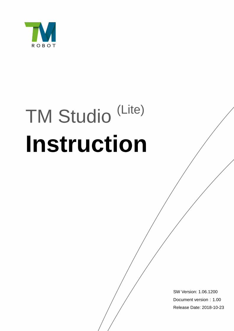
After selecting the circular arc feature, the point feature can be selected on the circular arc feature by
selecting the function of point feature.
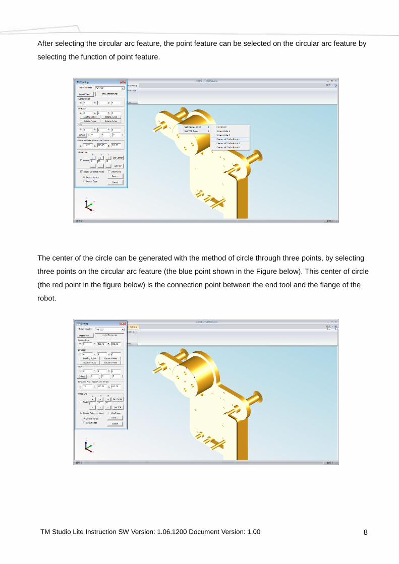
The center of the circle can be generated with the method of circle through three points, by selecting
three points on the circular arc feature (the blue point shown in the Figure below). This center of circle
(the red point in the figure below) is the connection point between the end tool and the flange of the
robot.
TM Studio Lite Instruction SW Version: 1.06.1200 Document Version: 1.00 9
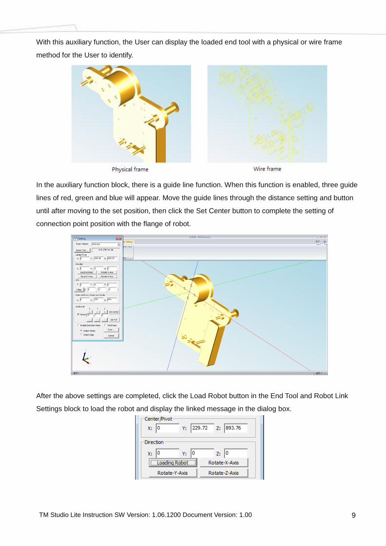
With this auxiliary function, the User can display the loaded end tool with a physical or wire frame
method for the User to identify.
In the auxiliary function block, there is a guide line function. When this function is enabled, three guide
lines of red, green and blue will appear. Move the guide lines through the distance setting and button
until after moving to the set position, then click the Set Center button to complete the setting of
connection point position with the flange of robot.
After the above settings are completed, click the Load Robot button in the End Tool and Robot Link
Settings block to load the robot and display the linked message in the dialog box.

TM Studio Lite Instruction SW Version: 1.06.1200 Document Version: 1.00 10
After loading the robot, since the position setting has been completed, the remaining angle setting can
be set by the three flipped buttons, as shown in the Figure below.
TCP Setting 2.4
With the same feature selection process to find the TCP of the circular feature, first click the red TCP
circle in the Figure, then click the Offset button in the TCP setting to complete the TCP setting. As shown
in the Figure below.

TM Studio Lite Instruction SW Version: 1.06.1200 Document Version: 1.00 11
In addition to the circular arc feature, the setting can also be done with the midpoint of two diagonal
points with the same way of selecting the line segment first, then selecting the point position, if there is a
cusp, and then the cusp can be selected as TCP directly, as shown in the Figure below.
Save 2.5
After all operations are completed, click the Save button at the bottom of the dialog box will save the
TCP information, as shown in the Figure below. It should be noted that this file will be related to the initial
setting of the robot module. If the initial selection is a 700-type arm, then this file is only applicable to the
use of 700-type arm.
When saving the .tcp file, it will generate a TCP.zip file for the robot to import. This file has the relative
relationship between the TCP of the end tool and the robot flange, and other information of pointing and
quality shall be input into the TCP settings after imported.
Reminder: When entering the TCP file name, it is recommended to use the filename with "English
Characters", and make sure that there is no Chinese file name in the Save path to avoid generating
error messages.

TM Studio Lite Instruction SW Version: 1.06.1200 Document Version: 1.00 12
3. Easy Workstation Creating
In this module, the User can load a self-designed workstation surrounding environment. With the relative
relationship between the processes setting environment and the robot to follow up with the Robot
Controller to operate the robot and perform the measurement of distance through the measurement
function.
Robot Loading 3.1
In the Easy Workstation Creating module, click the Open function to open the dialog box for subsequent
settings. The location of the Open button is as shown in the Figure below.
The dialog box opened after clicking the Open function. The User can select the object to be loaded in
this dialog box, including the selection of robot and the existing operation unit module.Select the robot to
be used and click the Open File to load the robot, as shown in the Figure below.

TM Studio Lite Instruction SW Version: 1.06.1200 Document Version: 1.00 13
If selecting the saved operation unit module, the previous saved operation unit can be displayed after
opened.

TM Studio Lite Instruction SW Version: 1.06.1200 Document Version: 1.00 14
External Object Loading 3.2
In the Easy Workstation Creating module, click the Start function to open the Layout dialog box to
perform subsequent settings of robot height, simple modeling, and external image loading and
movement, etc. The location of the Start button is as shown in the Figure below.
The dialog box opened after clicking the Start function is shown in the Figure below. All flow functions
provided by this dialog box include ground display, robot height setting, inserting geometry object,
loading object, as well as object movement and color allocation functions.
TM Studio Lite Instruction SW Version: 1.06.1200 Document Version: 1.00 15
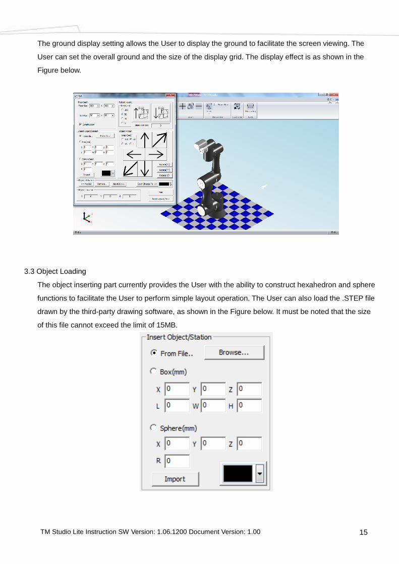
The ground display setting allows the User to display the ground to facilitate the screen viewing. The
User can set the overall ground and the size of the display grid. The display effect is as shown in the
Figure below.
Object Loading 3.3
The object inserting part currently provides the User with the ability to construct hexahedron and sphere
functions to facilitate the User to perform simple layout operation. The User can also load the .STEP file
drawn by the third-party drawing software, as shown in the Figure below. It must be noted that the size
of this file cannot exceed the limit of 15MB.
TM Studio Lite Instruction SW Version: 1.06.1200 Document Version: 1.00 16
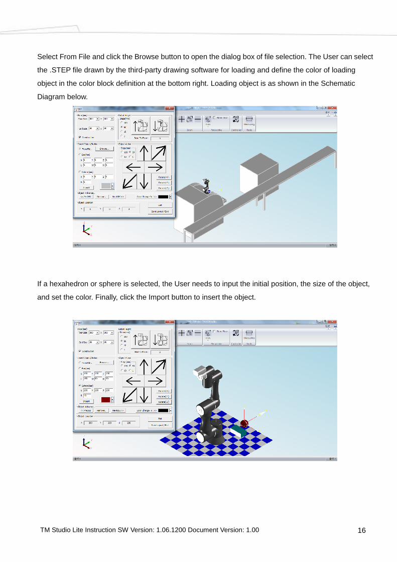
Select From File and click the Browse button to open the dialog box of file selection. The User can select
the .STEP file drawn by the third-party drawing software for loading and define the color of loading
object in the color block definition at the bottom right. Loading object is as shown in the Schematic
Diagram below.
If a hexahedron or sphere is selected, the User needs to input the initial position, the size of the object,
and set the color. Finally, click the Import button to insert the object.

TM Studio Lite Instruction SW Version: 1.06.1200 Document Version: 1.00 17
Object and Robot Movement 3.4
The robot movement and the object movement are divided into two parts. The Figure below shows the
function block for adjusting the horizontal height of the robot.
Through different distance selections, click the up and down buttons to adjust the robot's horizontal
height relative to the movement method. Adjusting the position of the object needs to be performed
through the button in the object motion block. This block provides three-dimensional translation of the
object in the space XYZ and the function of flipping along the three-axis XYZ. It should be noted that
each flip here is 90 degrees and the flip axis is the XYZ axis of the origin of the object, as shown in the
Figure below.
TM Studio Lite Instruction SW Version: 1.06.1200 Document Version: 1.00 18
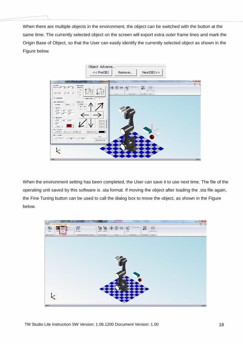
When there are multiple objects in the environment, the object can be switched with the button at the
same time. The currently selected object on the screen will export extra outer frame lines and mark the
Origin Base of Object, so that the User can easily identify the currently selected object as shown in the
Figure below.
When the environment setting has been completed, the User can save it to use next time. The file of the
operating unit saved by this software is .sta format. If moving the object after loading the .sta file again,
the Fine Tuning button can be used to call the dialog box to move the object, as shown in the Figure
below.

TM Studio Lite Instruction SW Version: 1.06.1200 Document Version: 1.00 19
At this time, the User can click the object in the environment with the mouse directly, and then through
the button of the above dialog box to translate and rotate the object.

TM Studio Lite Instruction SW Version: 1.06.1200 Document Version: 1.00 20
End Tool Mounting 3.5
From the description of the previous chapter, the User can save the self-drawn end tool as a .tcp file for
subsequent use. After loading the robot, the robot kinematics will be loaded at the same time as shown
in the Figure below.
After loading the correct robot kinematics, click the Attach button to call the dialog box to select the end
tool to be used.

TM Studio Lite Instruction SW Version: 1.06.1200 Document Version: 1.00 21
If the robot used to set the end tool is the same model as the one currently loaded, the loaded end tool
will be properly attached to the robot flange, as shown in the Figure below.
To remove the end tool can be done by clicking the Remove button to the right of the Attach button.
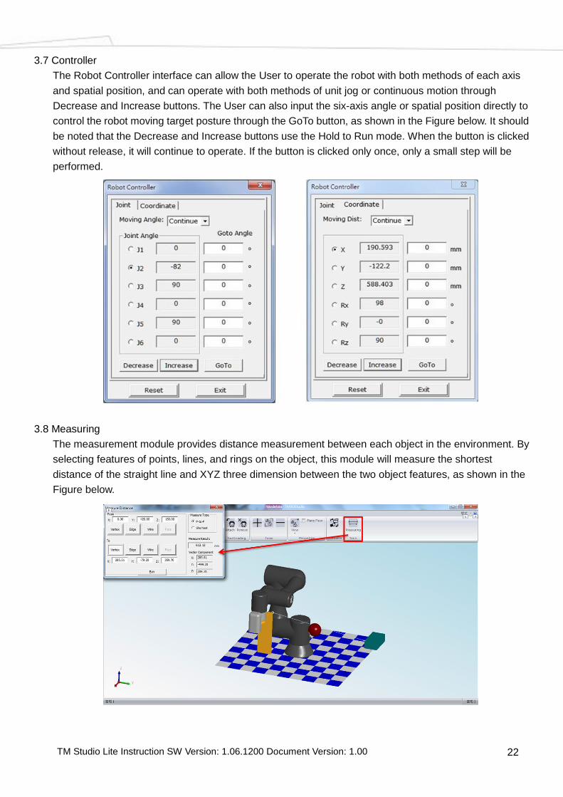
Robot Controller 3.6
After completing the robot image file loading and set the correct robot kinematics, the User can click the
Controller button to call the Robot Controller, as shown in the Figure below.
TM Studio Lite Instruction SW Version: 1.06.1200 Document Version: 1.00 22
Controller 3.7
The Robot Controller interface can allow the User to operate the robot with both methods of each axis
and spatial position, and can operate with both methods of unit jog or continuous motion through
Decrease and Increase buttons. The User can also input the six-axis angle or spatial position directly to
control the robot moving target posture through the GoTo button, as shown in the Figure below. It should
be noted that the Decrease and Increase buttons use the Hold to Run mode. When the button is clicked
without release, it will continue to operate. If the button is clicked only once, only a small step will be
performed.
Measuring 3.8
The measurement module provides distance measurement between each object in the environment. By
selecting features of points, lines, and rings on the object, this module will measure the shortest
distance of the straight line and XYZ three dimension between the two object features, as shown in the
Figure below.

TM Studio Lite Instruction SW Version: 1.06.1200 Document Version: 1.00 23
On Feature Selection, the detection of the point feature allows the User to directly select the point
feature of the object as the basis for measurement, as shown in the Figure below.
The detection of the line segment feature allows the User to first select the line segment feature of the
object, and mark the point on the line segment for the User to select, and use the last selected point as
the basis for measurement, as shown in the Figure below.
The detection of ring feature allows the User to first select the ring feature of the object. This ring feature
is a closed line segment feature with the same way to mark the point on the ring for the User to select,
and use the last selected point as the basis for measurement, as shown in the Figure below.
TM Studio Lite Instruction SW Version: 1.06.1200 Document Version: 1.00 24
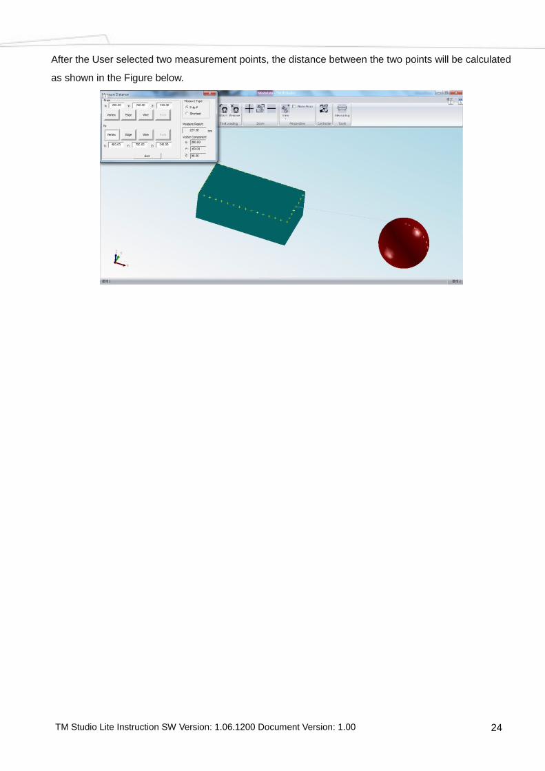
After the User selected two measurement points, the distance between the two points will be calculated
as shown in the Figure below.

TM Studio Lite Instruction SW Version: 1.06.1200 Document Version: 1.00 25
4. Workpiece Path Planning
On the TMflow Path node function, this module provides the User with an interface that is required to
achieve simple layout, selection of workpiece, planning line segment path, customized Tool, simulation,
and export Path file.
Robot Loading 4.1
In the Workpiece Path Planning module, click the function used to open a dialog for subsequent
settings. The User can select the robot module to be loaded in this dialog box.Select the robot to be
used and click the Open File to load the robot, as shown in the Figure below.

TM Studio Lite Instruction SW Version: 1.06.1200 Document Version: 1.00 26
External Object Loading 4.2
Click the function used to open the dialog box, the User can select the workpiece module,
workstation environment or project required to be loaded with this dialog box. Planning file is a project
that includes robots, external objects, path settings, paths, kinematics modules, and other settings. The
Figure below is the sample of import Planning file Project.

TM Studio Lite Instruction SW Version: 1.06.1200 Document Version: 1.00 27
Note: When importing the project, if the current robot module is different from the robot module in the
Planning file, a window will pop up asking if you would like to keep the current module, click Confirm to
keep, and click Cancel not to keep, as shown in the Figure below.
External Object Position Setting 4.3
Click the function used to open the dialog box is shown in the Figure below, Current Location
displays the current location of workpiece, and provides two methods to set the location of external
object. 1. Input the Target Location in Change To dialog box and press Apply. 2. In the Quick Move
Workpiece, run the XZY axis position moving with the arrow. The Step dialog box can set the distance
for each movement.

TM Studio Lite Instruction SW Version: 1.06.1200 Document Version: 1.00 28
Select Path 4.4
Click the function used to select the path, and the Select Mode provides the setting items for
the surface and line as shown in the Figure below, first select Face and clicks the specific Face on the
workpiece, and then select Edge to click the selected path on the Edge of specified surface. The path
will appear in a white box at this time. After completing the path selection, click Generate Path to
generate the path. Reverse Direction to reverse path direction, Reverse Normal to reverse normal
vector of the path.
TM Studio Lite Instruction SW Version: 1.06.1200 Document Version: 1.00 29
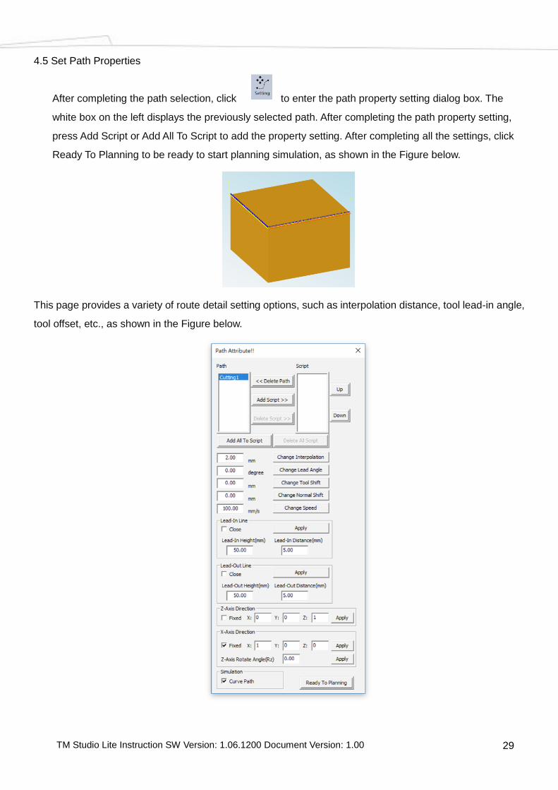
Set Path Properties 4.5
After completing the path selection, click to enter the path property setting dialog box. The
white box on the left displays the previously selected path. After completing the path property setting,
press Add Script or Add All To Script to add the property setting. After completing all the settings, click
Ready To Planning to be ready to start planning simulation, as shown in the Figure below.
This page provides a variety of route detail setting options, such as interpolation distance, tool lead-in angle,
tool offset, etc., as shown in the Figure below.

TM Studio Lite Instruction SW Version: 1.06.1200 Document Version: 1.00 30
Select Robot Kinematics & Set End Tool 4.6
From the description of the previous chapter, the User can save the self-drawn end tool as a .tcp file for
subsequent use. After loading the robot, the robot kinematics will be loaded at the same time as shown
in the Figure below.
After loading the correct robot kinematics, click the button to call the dialog box to select the end
tool to be used. If the robot used to set the end tool is the same model as the one currently loaded, the
loaded end tool will be properly attached to the robot flange, as shown in the Figure below.
To remove the end tool can be done by clicking the button. To plan the path direction with
flange, select “TOOL-NULL.tcp”.

TM Studio Lite Instruction SW Version: 1.06.1200 Document Version: 1.00 31
Start Path Planning 4.7
After completing the above setting steps, click to start running the Path Planning. At this time,
a Base Transfer window will pop up as shown in the Figure below. The User can input X, Y, Z, a, b, c
parameters before starting path planning to adjust the location of workpiece, if move the workpiece
again is not required, click Skip to start Path Planning. In the process of Path Planning, will be
displayed to indicate the progress of planning. When the green frame is full it indicates the Path
Planning is completed.
Note: If the Path cannot be successfully planned because the robot exceeded the workspace or passed
through singular point, the warning window will pop up, as shown in the Figure below.
Path Planning simulation 4.8
Click to display the Robot Simulation Motion. Click to Stop Simlation.
Export Path File/Project 4.9
The Workpiece Path Planning Module provides two export options, can export the Path file of Path
Planning Completion, or the Workpiece Path Planning Project as in the Figure below.

TM Studio Lite Instruction SW Version: 1.06.1200 Document Version: 1.00 32
The Path file can be used with the Path Node function. Importing the Path file in the TMflow Path node
to read the planned path. The following Figure is the export Path page. Set the path name and speed
(0~4500mm/s) and it displays the export address.
Note 1: The path speed of 4500mm/s is the upper speed limit for TMflow TCP Speed safety setting.
Note 2: When entering the Path file name, it is recommended to use the filename with "English
Characters" to avoid generating error messages.
The export project saves the complete Workpiece Path Planning details, including the settings for the
scene, workpiece, workpiece location, path, path properties, robot kinematics, and end tool. After the
export, the User can click Import to run the existing project and click Select Planning directly to run Path
Planning.
