tmi-2 accident scenario developmenta abstract tmi-2... · tmi-2 accident scenario developmenta e....
TRANSCRIPT
TMI-2 ACCIDENT SCENARIO DEVELOPMENTa
E. L. Tolman, P. Kuan, and J. M. BroughtonIdaho National Engineering Laboratory
EG&G Idaho, Inc.P.O. Box 1625
Idaho Falls, Idaho 83415
ABSTRACT
A best-estimate accident scenario describing the importantmechanisms that controlled the core damage progression during theTMI-2 accident has been described in previous papers and reports.Several important questions were identified in these documents forwhich additional analysis and/or data are necessary to develop anadequate understanding. This paper summarizes recent analyticalwork relating to: (a) configuration of the degraded core based oninterpreting the source range monitor data, (b) the coolability ofthe upper core debris bed, (c) potential crust failure mechanismsand the interaction of the molten core material with the reactorvessel coolant, and (d) potential reactor vessel damage.
INTRODUCTION
The TMI-2 accident resulted in extensive damage to the reactor core andsignificant release of fission products from the fuel. Defueling data hasconfirmed that approximately 30% of the original core material (50 metrictons) achieved melting temperatures and an estimated 15 metric tons of moltencore material relocated to the lower plenum region of the reactorvessel.1 ,2 Because of the extensive core damage, the TMI-2 accident offersa unique opportunity to extend our knowledge of important physical mechanismsaffecting core damage progression and fission product behavior for a severeaccident under achievable reactor system conditions.
The TMI-2 Accident Evaluation Program3 is being conducted for the U.S.Department of Energy as a severe accident research effort to develop aconsistent understanding of the mechanisms controlling the core damageprogression and resulting fission product behavior during the TMI-2accident. This goal is being achieved through:
e Inspection and characterization of the end-state core materialdistribution and damage state of the core, core support assembly(CSA), and reactor vessel,
* Interpretation and qualification of the TMI-2 data recorded duringthe accident as it relates to the reactor system thermal hydraulicresponse, and
a. Work supported by the U.S. Department of Energy Assistant Secretary forNuclear Energy, Office of LWR Safety and Technology under DOE Contract No.DE-AC07-761D01570.
155
e Analysis work to integrate these data into a consistent scenario ofcore damage progression and fission product behavior.
Details of the core damage progression (accident scenario) have beendocumented in previous papers4 #5 and reports.6 A summary of the timingand major physical mechanisms hypothesized to have controlled the core damageprogression is given in Table 1. Important questions relative to themechanisms that controlled the core damage progression have been furtherinvestigated this year. These include the following:
1. What was the extent of core material relocation before the pumptransient (and upper debris formation)?
2. What was the coolability of the upper core debris bed formed as aresult of the pump transient at 174 min?
3. What was the mechanism that caused crust failure at 224 min?
4. What was the interaction of the molten core material with thereactor vessel coolant?
5. What was the potential damage to the reactor vessel?
Discussions of recent analytical work relative to each of these areas areprovided in the following sections.
TIMING AND EXTENT OF CORE MATERIAL RELOCATION
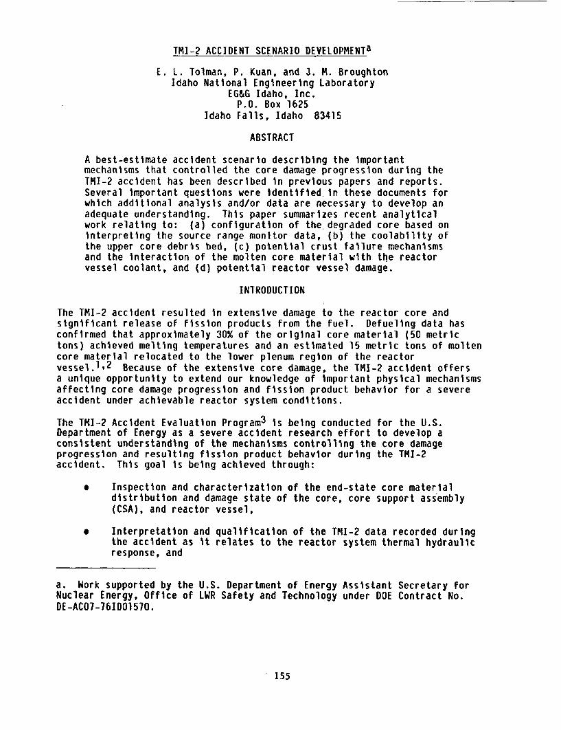
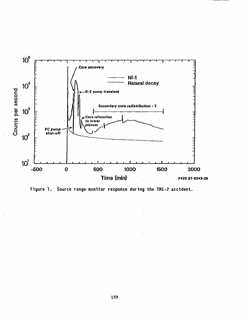
The available TMI-2 data indicate that severe damage of the core had occurredby between 150-160 min and that a major relocation of core materials occurredbetween 224-226 min (see Table 1). The source range monitor (SRM) locatedoutside the reactor vessel at the core mid-plane provided a signature of thechanging conditions within the reactor vessel. Figure 1 compares themeasured SRM response to the normal detector count rate after shutdown.Three features of the SRM response are important relative to the coreconfiguration: (a) the rapid drop in detector count rate coincident with theB-pump transient (174 min), (b) the rapid increase between 224-226 min, and(c) the longer-term response between 400-1500 min showing a slowly increasingand then decreasing trend.
The rapid decrease in the SRM response at 174 min provides a unique benchmarkto evaluate the degraded core configuration. Notice, however, that the SRMcount rate did not decrease fully to the normal shutdown level. Thus, it canbe hypothesized that (a) the core region was not filled with water, and/or(b) the core configuration had changed significantly. The previousinterpretation of SRM data1 assumed that the core was intact, thus givingno insight into the effect of core material relocation on the detectorresponse.
Recent neutronic analysis8 has been completed to evaluate the effect ofcore material relocation (both fuel and control rod material) on the SRM
156
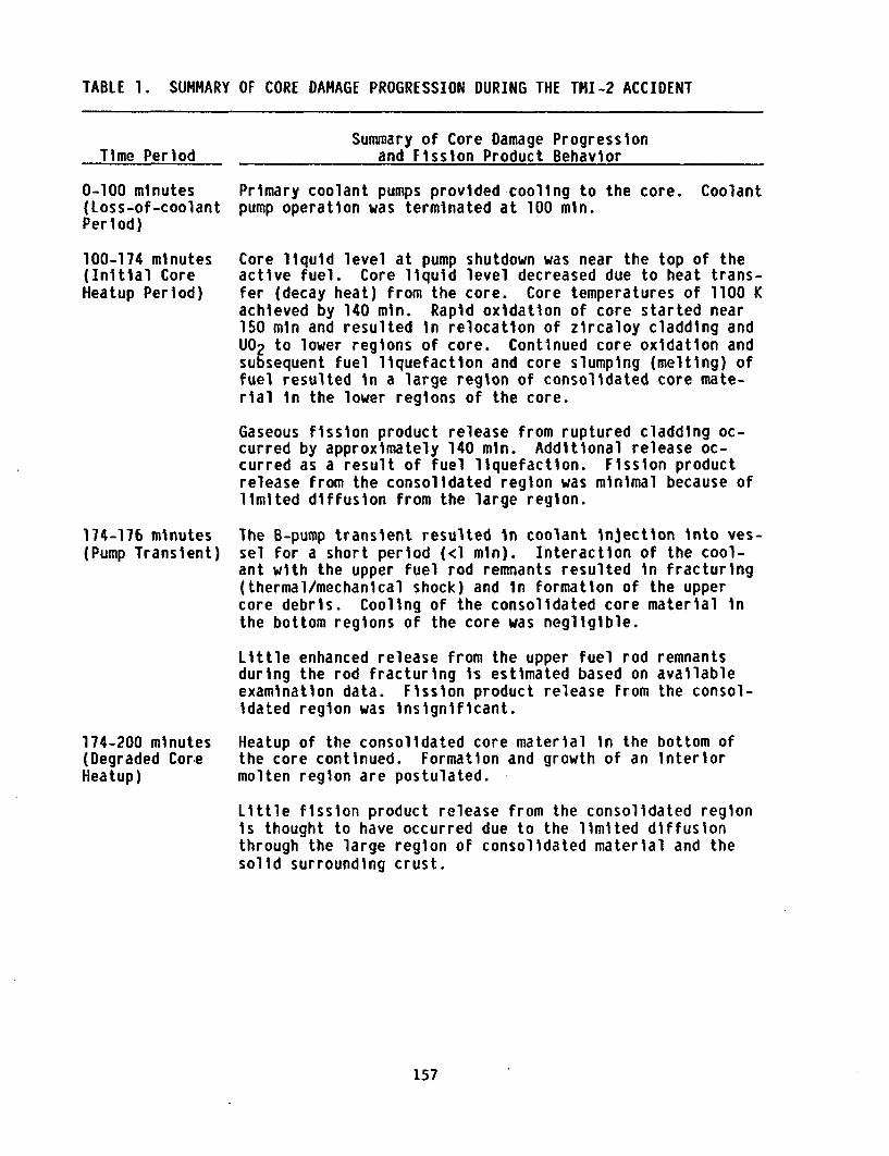
TABLE 1. SUMMARY OF CORE DAMAGE PROGRESSION DURING THE TMI-2 ACCIDENT
Summary of Core Damage Progressionand Fission Product BehaviorTime Period
0-100 minutes(Loss-of-coolantPeriod)
100-174 minutes(Initial CoreHeatup Period)
Primary coolant pumps provided cooling to the core.pump operation was terminated at 100 min.
Coolant
Core liquid level at pump shutdown was near the top of theactive fuel. Core liquid level decreased due to heat trans-fer (decay heat) from the core. Core temperatures of 1100 Kachieved by 140 min. Rapid oxidation of core started near150 min and resulted in relocation of zircaloy cladding andU02 to lower regions of core. Continued core oxidation andsubsequent fuel liquefaction and core slumping (melting) offuel resulted in a large region of consolidated core mate-rial in the lower regions of the core.
Gaseous fission product release from ruptured cladding oc-curred by approximately 140 min. Additional release oc-curred as a result of fuel liquefaction. Fission productrelease from the consolidated region was minimal because oflimited diffusion from the large region.
174-176 minutes(Pump Transient)
The B-pump transient resulted in coolant injection into ves-sel for a short period (<1 min). Interaction of the cool-ant with the upper fuel rod remnants resulted in fracturing(thermal/mechanical shock) and in formation of the uppercore debris. Cooling of the consolidated core material inthe bottom regions of the core was negligible.
Little enhanced release from the upper fuel rodduring the rod fracturing is estimated based onexamination data. Fission product release fromidated region was insignificant.
remnantsavailablethe consol-
174-200 minutes(Degraded Cor-eHeatup)
Heatup of the consolidated core material in thethe core continued. Formation and growth of anmolten region are postulated. ;
bottom ofinterior
Little fission product release from the consolidated regionis thought to have occurred due to the limited diffusionthrough the large region of consolidated material and thesolid surrounding crust.
157
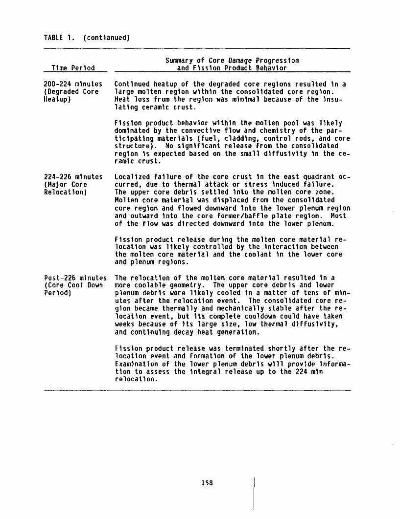
TABLE 1. (contianued)
Time PeriodSummary of Core Damage Progression
and Fission Product Behavior
200-224 minutes(Degraded CoreHeatup)
Continued heatup of the degraded core regions resulted in alarge molten region within the consolidated core region.Heat loss from the region was minimal because of the insu-lating ceramic crust.
Fission product behavior within the molten pool was likelydominated by the convective flow and chemistry of the par-ticipating materials (fuel, cladding, control rods, and corestructure). No significant release from the consolidatedregion is expected based on the small diffusivity in the ce-ramic crust.
224-226 minutes(Major CoreRelocation)
Localized failure of the core crust in the east quadrant oc-curred, due to thermal attack or stress induced failure.The upper core debris settled into the molten core zone.Molten core material was displaced from the consolidatedcore region and flowed downward into the lower plenum regionand outward into the core former/baffle plate region. Mostof the flow was directed downward into the lower plenum.
Fission product release during the molten core material re-location was likely controlled by the interaction betweenthe molten core material and the coolant in the lower coreand plenum regions.
Post-226 minutes(Core Cool DownPeriod)
The relocation of the molten core material resulted in amore coolable geometry. The upper core debris and lowerplenum debris were likely cooled in a matter of tens of min-utes after the relocation event. The consolidated core re-gion became thermally and mechanically stable after the re-location event, but its complete cooldown could have takenweeks because of its large size, low thermal diffusivity,and continuing decay heat generation.
Fission product release was terminated shortly after the re-location event and formation of the lower plenum debris.Examination of the lower plenum debris will provide informa-tion to assess the integral release up to the 224 minrelocation.
158
Sc) ' ' ' ' I ' 'j T-.--- * * I * f
Core uncovery
NI-i104 ------ Natural decay
. <4-8-2 pumip tranalent0
to Secondary core redistribution - I
a103 _ _ _ __:xCore relocation
to lowerC - plenumo PC pump 'o Q shut-off
10~ _ * t * . a a p. ... I_ * a a
-600 0 500 1000 1500 2000Time (min) P420 ST-0243-29
Figure 1. Source range monitor response during the TMI-2 accident.
159
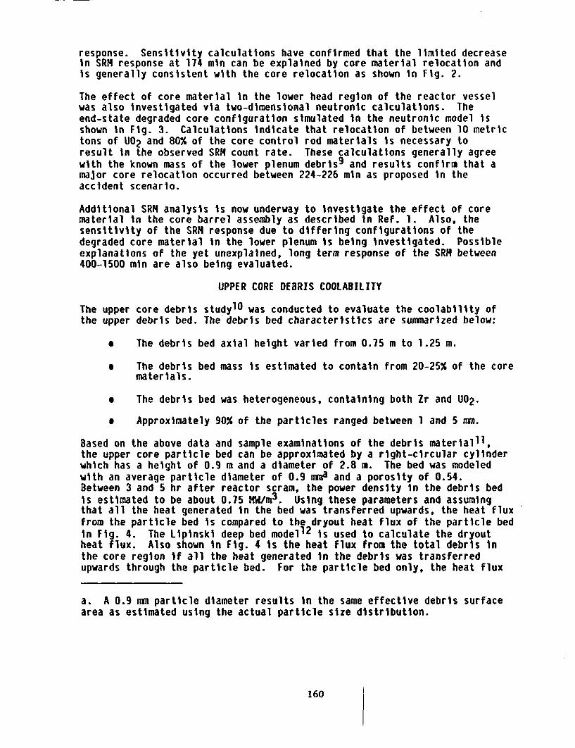
response. Sensitivity calculations have confirmed that the limited decreaseIn SRM response at 174 min can be explained by core material relocation andis generally consistent with the core relocation as shown in Fig. 2.
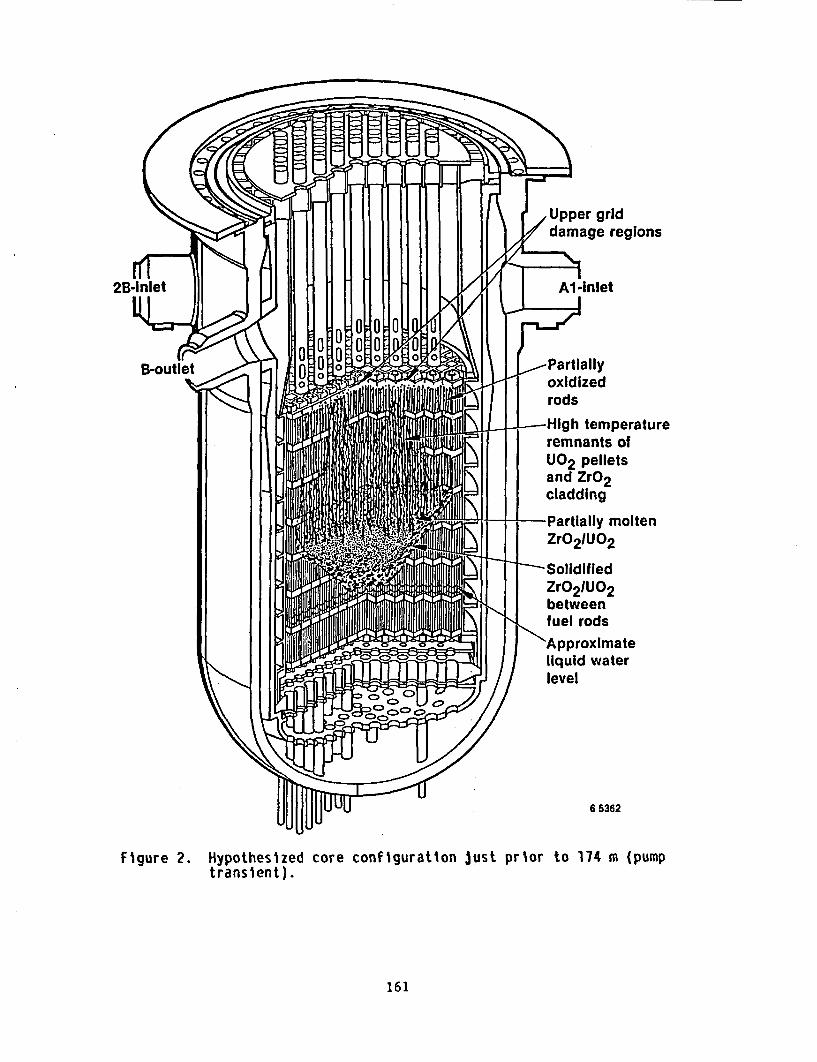
The effect of core material in the lower head region of the reactor vesselwas also investigated via two-dimensional neutronic calculations. Theend-state degraded core configuration simulated in the neutronic model isshown in Fig. 3. Calculations indicate that relocation of between 10 metrictons of U02 and 80% of the core control rod materials is necessary toresult in the observed SRM count rate. These calculations generally agreewith the known mass of the lower plenum debris9 and results confirm that amajor core relocation occurred between 224-226 min as proposed in theaccident scenario.
Additional SRM analysis is now underway to investigate the effect of corematerial in the core barrel assembly as described in Ref. 1. Also, thesensitivity of the SRM response due to differing configurations of thedegraded core material in the lower plenum is being investigated. Possibleexplanations of the yet unexplained, long term response of the SRM between400-1500 min are also being evaluated.
UPPER CORE DEBRIS COOLABILITY
The upper core debris studyl1 was conducted to evaluate the coolability ofthe upper debris bed. The debris bed characteristics are summarized below:
e The debris bed axial height varied from 0.75 m to 1.25 m.
* The debris bed mass is estimated to contain from 20-25% of the corematerials.
* The debris bed was heterogeneous, containing both Zr and U02.
e Approximately 90% of the particles ranged between 1 and 5 mm.
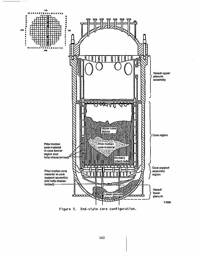
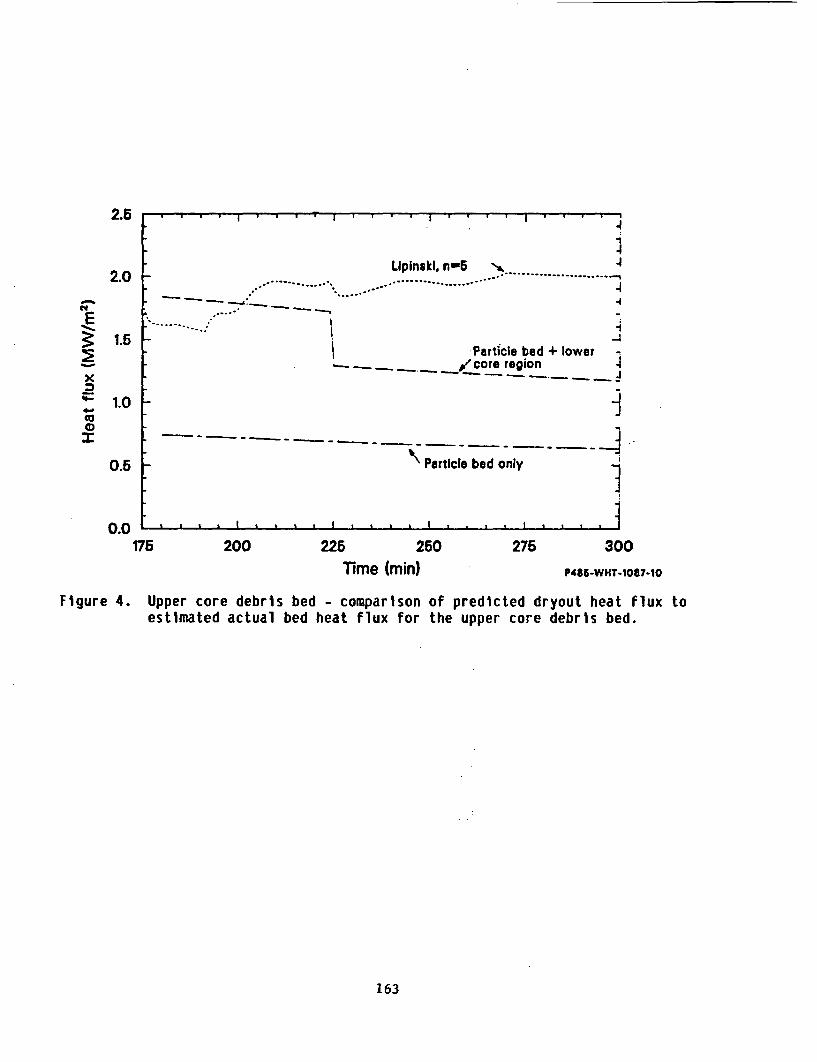
Based on the above data and sample examinations of the debris material11 ,the upper core particle bed can be approximated by a right-circular cylinderwhich has a height of 0.9 m and a diameter of 2.8 m. The bed was modeledwith an average particle diameter of 0.9 mma and a porosity of 0.54.Between 3 and 5 hr after reactor scram, the power density in the debris bedis estimated to be about 0.75 MW/m 3. Using these parameters and assumingthat all the heat generated in the bed was transferred upwards, the heat fluxfrom the particle bed is compared to the dryout heat flux of the particle bedin Fig. 4. The Lipinski deep bed modell2 is used to calculate the dryoutheat flux. Also shown in Fig. 4 is the heat flux from the total debris inthe core region if all the heat generated in the debris was transferredupwards through the particle bed. For the particle bed only, the heat flux
a. A 0.9 mm particle diameter results in the same effective debris surfacearea as estimated using the actual particle size distribution.
160
grid
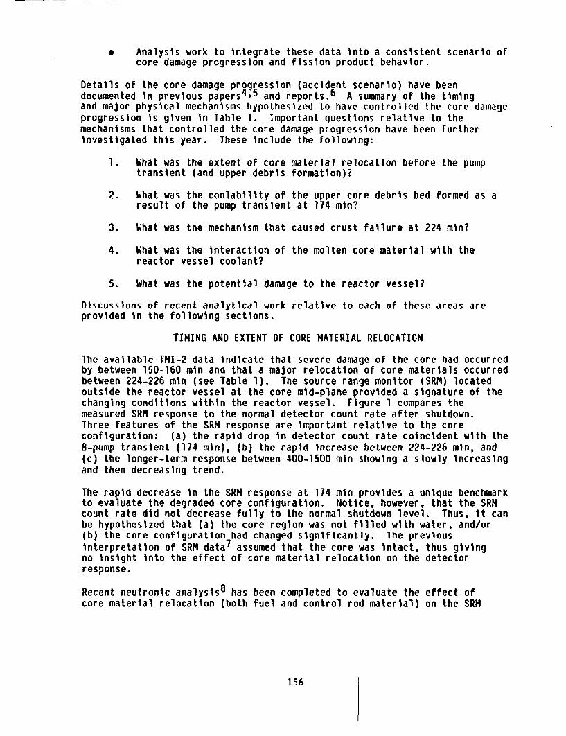
-High temperatureremnants ofU02 pelletsand ZrO2cladding
-Partially moltenZrO 2IUO2
SolidifiedZrO2 1UO 2betweenfuel rods'Approximateliquid waterlevel
6 5362
Figure 2. Hypothesized core configuration Just prior to 174 m (pumptransient).
161
II
14
14S
X(a
AAABCDEFONKLUNOPma
Vessel upperplenumassembly
Core region
Core supportassemblyregion
Vessel) lower
plenum
7-3229
Figure 3. End-state core configuration.
162
2.6 - -- - - - - - - - - - - - - - - - - - - - - - - - -
Lipinski. n'5 A 4... .. . .*
2.0
xED
r.-4-
(0(0
.
- -- - ....... :.....
.4
!I 1
1.5
1.0
I Particle bed + lower -
I _ o region i
_j
-'\" Particle bed only
. I. . I . . .. I . . 11 . I . - i . . . .A
0.5
0.0175 200 225 250 275 300
Time (min) P485-WHT-1087-1O
Figure 4. Upper core debris bed - comparison of predicted dryout heat flux toestimated actual bed heat flux for the upper core debris bed.
163
was much lower than the dryout heat flux and the particle bed was coolable inthe presence of water. The debris bed heat flux (assuming most of the heatfrom the consolidated region was transfered upward into the debris bed) wascomparable to the dryout heat flux before the relocation (174-224 min).Thus, the debris bed may not have been cooled appreciably during this timeperiod. After the major core relocation at 224 min, however, the heat fluxin the debris dropped due to the removal of fuel and the particle bed becamecoolable even if all the heat in the lower consolidated region wastransferred upward through the particle bed.
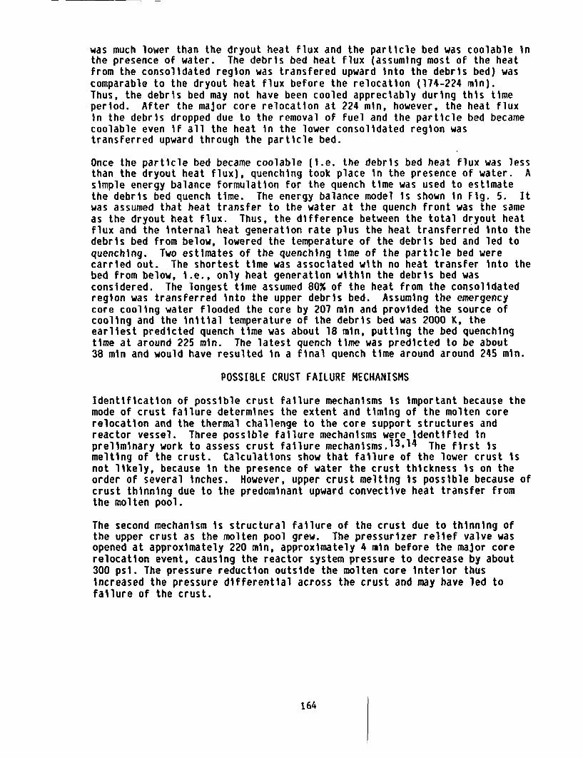
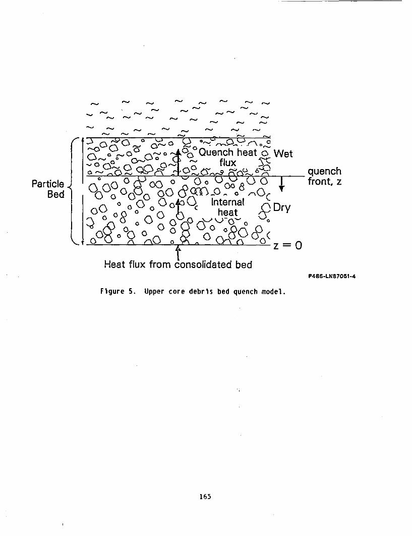
Once the particle bed became coolable (i.e. the debris bed heat flux was lessthan the dryout heat flux), quenching took place in the presence of water. Asimple energy balance formulation for the quench time was used to estimatethe debris bed quench time. The energy balance model is shown in Fig. 5. Itwas assumed that heat transfer to the water at the quench front was the sameas the dryout heat flux. Thus, the difference between the total dryout heatflux and the internal heat generation rate plus the heat transferred into thedebris bed from below, lowered the temperature of the debris bed and led toquenching. Two estimates of the quenching time of the particle bed werecarried out. The shortest time was associated with no heat transfer into thebed from below, i.e., only heat generation within the debris bed wasconsidered. The longest time assumed 80% of the heat from the consolidatedregion was transferred into the upper debris bed. Assuming the emergencycore cooling water flooded the core by 207 min and provided the source ofcooling and the initial temperature of the debris bed was 2000 K, theearliest predicted quench time was about 18 min, putting the bed quenchingtime at around 225 min. The latest quench time was predicted to be about38 min and would have resulted in a final quench time around around 245 min.
POSSIBLE CRUST FAILURE MECHANISMS
Identification of possible crust failure mechanisms is important because themode of crust failure determines the extent and timing of the molten corerelocation and the thermal challenge to the core support structures andreactor vessel. Three possible failure mechanisms were identified inpreliminary work to assess crust failure mechanisms.13'14 The first ismelting of the crust. Calculations show that failure of the lower crust isnot likely, because in the presence of water the crust thickness is on theorder of several inches. However, upper crust melting is possible because ofcrust thinning due to the predominant upward convective heat transfer fromthe molten pool.
The second mechanism is structural failure of the crust due to thinning ofthe upper crust as the molten pool grew. The pressurizer relief valve wasopened at approximately 220 min, approximately 4 min before the major corerelocation event, causing the reactor system pressure to decrease by about300 psi. The pressure reduction outside the molten core interior thusincreased the pressure differential across the crust and may have led tofailure of the crust.
164
fl.j0--.O
-.. O e-.0#-� r.-.0
-.. O 0-..O0-� 0-�
1-0
a-., p-
,h heat o WetJX 3-CPu& m~ quench
front, zParticleBed
Heat flux from consolidated bed
Figure 5. Upper core debris bed quench model.
P485-LN87051-4
165
The third possible mechanism is the potential interaction of the degradedcore materials with the core barrel assembly at the core periphery. Thedegraded core region was skewed to the east side of the vessel and, as thedegraded core heated up, it may have caused melting of the core barrelstructures which chemically attacked the crust, resulting in crust failure.
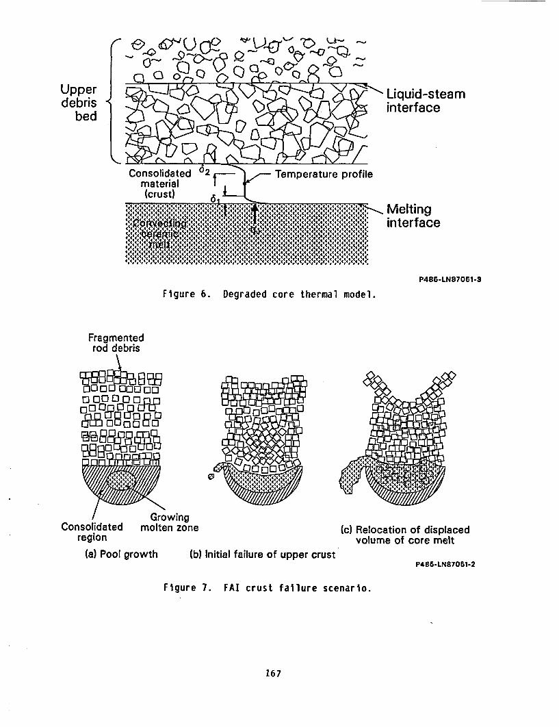
Details of a hypothesized crust failure scenariol5 have been proposed basedon the thermal properties of the degraded core material as shown in Fig. 6.Because of the ceramic properties of the consolidated material, thetemperature profile across the consolidated region would be expected to berelatively constant, as shown in Fig. 6. Significant heat transfer into orout of the consolidated region would occur only at the thermal boundary layeradjacent to the molten region, 6l, and at the upper coolant interface,62, as shown in Fig. 6. The estimated thickness of these thermalboundary layers is only a few millimeters. Thus, little heat is transferredfrom the consolidated region, and the internal heat generation resultsprimarily in melting the interior region and formation of a molten pool asshown in Fig. 7(a). As the molten core material regions grows, eventualinteraction of the two thermal boundaries shown in Fig. 6 will occur.
Calculations indicate that for a molten pool of 1.25 m radius In equilibriumwith the surrounding coolant, the equilibrium crust thickness at the outersurface would be approximately 8 mm. Previous estimates of the crustthickness necessary to support the upper debris bed mass indicate that acrust at least 2.5 cm thick is required. Experiments to measure heat fluxvariations in convective pools indicate that nonuniform heat fluxes wouldlikely occur in the molten pool, resulting in thinner crusts at the top andat the periphery. These trends, together with a slight skewing of thedegraded core region towards the east side of the vessel, are hypothesized tohave led to localized failure of the crust near the core periphery as shownconceptually in Fig. 7(b). As the upper crust failed, the upper debris bedwould fall into the molten pool, displacing the molten core materials fromthe core region as shown in Fig. 7(c). Estimates of the time it took todisplace the molten core material were made by balancing the drag and gravityforces on the debris particles as they settled into the molten pool. Thetime required to displace the molten core material in the form of a liquidwas calculated to be about 12 s. This is somewhat shorter than the maximumrelocating time of about 1 min as inferred from the source range monitordata. The time difference can be explained by considering solidification ofthe molten ceramic in the interstices of the particles, which is calculatedto have prolonged the settling time by an estimated 1 min.
MOLTEN FUEL COOLANT INTERACTION
An evaluation of the interaction of the molten core material with the waterin the reactor vessel is also documented in Ref. 15. Breakup of the moltencore material stream was analyzed in terms of the growth and detachment ofunstable capillary waves or surface ripples on the outer surface of themolten stream or jet. The rate of stream breakup, via the surface waveinstability theory, has a square-root dependence on the fluid densitysurrounding the jet. If the water along the path of jet movement wassaturated, the fluid responsible for the breakup of the jet would have been
166
Upperdebris
bed
-j >Liquid-steaminterface
Consolidated 62 Temperature profilematerial(crust) s
444(44( Melting(((4444 interface
P486-LN87061-3
Figure 6. Degraded core thermal model.
Fragmentedrod debris
0000 00000
00°°O n
tBOOBOE Oj
GrowingConsolidated molten zone
region(c) Relocation of displaced
volume of core melt(a) Pool growth (b) Initial failure of upper crust
P485-LN87051-2
Figure 7. FAI crust failure scenario.
167
primarily steam, generated from film-boiling at the surface of the stream.For a stream velocity of 3.7 m/s, and a diameter of 0.08 m (based on anassumed relocation flow pathway of one fuel assembly and a relocation time of1 min), it would require a distance of about 7 m for complete stream breakupin saturated water. The distance from the mid-core elevation to the bottomof the lower head is about 4 m. Therefore, complete breakup of the jet wouldnot have been possible. In this case, the molten stream may have eroded thevessel head at the point of impingement.
If the water surrounding the jet was subcooled by about 80 K, the steam layerat the jet interface would have been thin, thus allowing interaction of thesurrounding water with the jet surface resulting in jet breakup. Due to thesquare-root dependence of the breakup rate on the fluid density, breakup ofthe jet is estimated to occur over a traveling distance of about 2 m, whichis about half the distance from the core mid-plane to the lower head.
Experiments in which molten core material was dropped into water pools,16
also show that subcooled water results in particulate debris formation andlimited steam generation compared to experiments with saturated water, Inwhich much less molten stream breakup occurred and much higher steamgeneration was measured.
POTENTIAL VESSEL HEAD DAMAGE
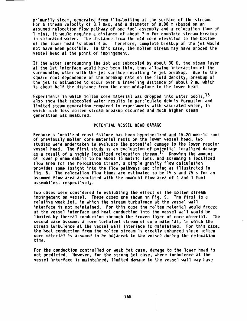
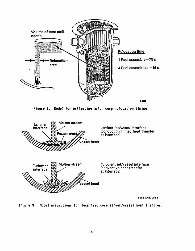
Because a localized crust failure has been hypothesized and 15-20 metric tonsof previously molten core material rests on the lower vessel head, twostudies were undertaken to evaluate the potential damage to the lower reactorvessel head. The first study is an evaluation of potential localized damageas a result of a highly localized relocation stream.17 Knowing the amountof lower plenum debris to be about 15 metric tons, and assuming a localizedflow area for the relocation stream, a simple gravity flow calculationprovides some insight into the flow pathways and timing as Illustrated inFig. 8. The relocation flow times are estimated to be 15 s and 75 s for anassumed flow area associated with the nominal flow area of 4 and 1 fuelassemblies, respectively.
Two cases were considered in evaluating the effect of the molten streamimpingement on vessel. These cases are shown in Fig. 9. The first is arelative weak jet, in which the stream turbulence at the vessel wallinterface is not maintained. For this case the molten material would freezeat the vessel interface and heat conduction into the vessel wall would belimited by thermal conduction through the frozen layer of core material. Thesecond case assumes a more turbulent stream of core material, in which thestream turbulence at the vessel wall interface is maintained. For this case,the heat conduction from the molten stream is greatly enhanced since moltencore material is assumed to be adjacent to the vessel during the relocationtime.
For the conduction controlled or weak jet case, damage to the lower head isnot predicted. However, for the strong jet case, where turbulence at thevessel interface is maintained, limited damage to the vessel wall may have
168
Volume of core-meltdebris
Relocationarea
Relocation time
I Fuel assembly-75 s
4 Fuel assemblies-15 s
74323
Figure 8. Model for estimating major core relocation timing.
. Molten stream"I/ Laminar jet/vessel interface(,. (conduction limited heat transferI," Frozen crush at interface)
head
Turbulent jet/vessel interface(convective heat transferat interface)
head
P485-LN87051-5
Figure 9. Model assumptions for localized core stream/vessel heat transfer.
169
occurred. Under these assumptions, limited surface ablation of the vesselliner is calculated. However, the melt front penetration of the vessel wallis estimated to be less than 1 cm. The calculations also indicate a directjet impingement of 15-20 min is necessary to cause melting of half of thevessel wall thickness. The TMI-2 data clearly do not support relocationtimes greater than about 1 min.
The second vessel study evaluated the global thermal response of the vesselassuming 15 metric tons of core debris on the vessel head.18 Atwo-dimensional (radial, axial) heat conduction model of the TMI-2 lowerplenum debris and reactor vessel was utilized to address the vesselmargin-to-failure question. Because the debris configuration during themolten core relocation period is somewhat uncertain, two assumed debrisconfigurations were analyzed. The first configureation assumed a porousdebris bed resting on the vessel head. The second assumed a porous debrisbed supported by a layer of previously molten but consolidated core materialadjacent to the vessel head. For each of these cases, two assumptions ondebris cooling were made, i.e., (a) no cooling of the debris material, and(b) heat transfer from the debris and consolidated material leading toquenching in a 20 min period. The general lower plenum debris and vesselhead model is shown in Fig. 10.
The analyses show that the vessel thermal response is sensitive to both thedebris configuration and cooling of the degraded core materials. For theconsolidated material configuration, if the upper debris is not cooled,vessel melting is predicted to occur after several hours. However, attemperatures in the range of 1000-1100 K, creep rupture of the vessel becomesan important issue since the reactor system pressures were high (7-10 MPa).Thus, it is expected that vessel failure due to creep rupture would likelyoccur before vessel melting temperatures are achieved. If cooling of theporous debris on top of the consolidated material is assumed, melting of thevessel is not predicted. However, the vessel temperatures are also predictedto exceed 1100 K for this case. Thus, for the lower plenum configurationwith consolidated material adjacent to the vessel, even with debris cooling,vessel creep rupture is an important issue.
For the case in which the lower plenum material is porous debris, vesselmelting is not predicted; however, again vessel wall temperatures of 1100 Kare predicted, indicating creep rupture of the vessel to be important.However, if cooling of the debris is assumed, vessel wall temperatures areestimated to be less than 800 K. For this case, mechanical challenge to thevessel would be insignificant.
SUMMARY
TMI-2 defueling data to characterize the core damage state and location ofthe degraded core materials, examination of the degraded core material fromthe TMI-2 core and lower plenum regions, interpretation of the TMI-2 on-linedata recorded during the accident, and supporting analyses are providing aremarkably consistent interpretation of the core damage progression thatoccurred during the TMI-2 accident. This work has provided a baseline
170
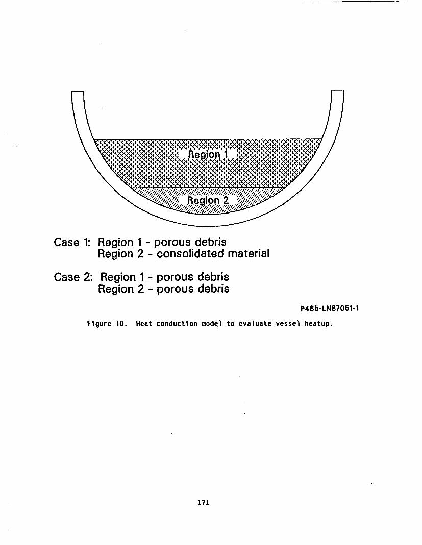
Case 1: Region 1 - porous debrisRegion 2 - consolidated material
Case 2: Region 1 - porous debrisRegion 2 - porous debris
P486-LN87051-1
Figure 10. Heat conduction model to evaluate vessel heatup.
171
accident scenario that defines the basic mechanisms that controlled the coredamage progression and has provided a baseline from which to interpret themeasured fission product distribution. The fission product behavior analysiswork based on the core damage progression scenario developed to date issummarized in Ref. 19.
The analytical studies summarized in this paper have significantly improvedour understanding of the mechanisms affecting the degraded core heatup, crustfailure mechanism, interaction of molten core material with the reactorvessel coolant, and the potential thermal challenge to the reactor vessel.Further analytical work to be completed in the next year will add insightinto the earlier phases of the core damage progression, particularlyregarding the impact of core flow blockage on the core heat transfer and onhydrogen production. In addition, work is ongoing to establish a betterunderstanding of the mechanisms leading to the damage of the upper gridstructures. Work will also be necessary to interpret the most recentobservation of very localized melt ablation of the lower fuel assembly gridplate in one of the centrally located fuel assemblies.
Completion of the core and lower vessel region defueling, examination ofdegraded core materials from these regions, and the necessary supportinganalytical work to interpret the data, will complete our understanding of the.accident and provide important data to assess more generic technical issuesrelative to core degradation and fission product behavior during severeaccidents in light water reactors.
REFERENCES
1. G. R. Eldam, NGPU Defueling," These proceedings, October 1987.
2. E. Tolman, et al., TMI-2 Core Bore Acquisition Summary Report,EGG-TMI-7385 (Rev. 1), February 1987.
3. E. Tolman, et al., TMI-2 Accident Evaluation Program, EGG-TMI-7048,February 1986.
4. E. Tolman, et al., "Thermal Hydraulic Features of the Accident," ACSSymposium Series 293, April 1985.
5. E. Tolman, et al., "TMI-2 Accident Scenario Update," Proceedings of 14thWater Reactor Safety Information Meeting, October 1986.
6. E. Tolman, et al., TMI-2 Accident Scenario Update, EGG-TMI-7489,December 1986.
7. Interpretation of TMI-2 Instrument Data, NSAC/28, Nuclear SafetyAnalysis Center (NSAC), Electric Power Research Institute (EPRI), PaloAlto, CA, March 1980.
172
8. Horng-Yu Wu, et al., Analysis of the TMI-2 Source Range Monitor Duringthe TMI Accident, Pennsylvania State University Report (NuclearEngineering Department), June 1987.
9. J. P. Adams, et al., TMI-2 Lower Plenum Video Data Summary,EGG-TMI-7429, July 1987.
10. P. Kuan, TMI-2 Upper-Core Particle Bed Thermal Behavior (Draft),EGG-TMI-7757, July 1987.
11. D. Akers, et al., TMI-2-Core Debris Grab Samples--Examination andAnalysis (Part 1), GEND-INF-075, September 1986.
12. R. J. Lipinski, "A Coolability Model for Post-Accident Nuclear ReactorDebris," Nuclear Technology, 65, 53, April 1984
13. R. Henry, et al., "Core Relocation Phenomenology," Proceedings of theFirst International Information Meeting on the TMI-2 Accident,CONF-8510166, Germantown, MD, October 1985.
14. P. Kuan, Core Relocation in the TMI-2 Accident, EGG-TMI-7402,December 1986.
15. M. Epstein, H. Fauske, The TMI-2 Core Relocation - Heat Transfer andMechanism, Fauske & Associates, Inc. Report FAI/87-49, July 1987.
16. B. Spencer, et al., "Corium Quench in pool mixing Experiments," ANSProceedings, 1985 NaturalHeat Transfer Conference, ANS 700101, Denver,CO, August 1985.
17. A. Cronenberg, E. Tolman, An Assessment of Damage Potential to theTMI-2 Baffle Plate, Core Former, and Lower Head Assemblies Due toThermal Attack by Core Debris, EGG-TMI-7790, September 1987.
18. R. Moore, TMI-2 Reactor Vessel Lower Head Heatup Calculations,EGG-TMI-7784, September 1987.
19. D. A. Petti et al., "Analysis of Fission Product Release Behavior Duringthe TMI-2 Accident", This proceeding, October 1987.
173