tmrt (thermal model reduction tool): presentation of the
TRANSCRIPT

46th International Conference on Environmental Systems ICES-2016-132 10-14 July 2016, Vienna, Austria
TMRT (Thermal Model Reduction Tool): Presentation of the tool and application on satellite model reduction for
launcher coupled analysis
Thierry Basset1, Patrick Hugonnot2, Patrick Connil3, Michèle Ferrier4
Thales Alenia Space, 100 Boulevard du Midi, 06150 Cannes, France
François Brunetti,5 DOREA - Résidence de l'Olivet, Bat F, 75 chemin de l'Olivet 06110 Le Cannet, France
From the seventies, Thales Alenia Space – Cannes has developed a long experience and expertise, in thermal software development. The core calculation modules and associated methodologies have been validated through several projects, i.e. thermal balance tests and flight correlations. In more recent years, different collaborations with IT services companies, mainly DOREA have allowed to improve these space thermal softwares. The study concerns the presentation of a specific module of the thermal software chain developed in TAS-Cannes (i.e. e-Therm). More precisely, this module named TMRT (Thermal Model Reduction Tool) is focused on the reduction of the number of nodes of an initial Detailed Thermal Mathematical Model (DTMM) (nodal model) by generating a final Reduced Thermal Mathematical Model (RTMM). It has to be noticed that TMRT tool is capable to handle with two thermal model formats: ESATAN-TMS and e-therm, for both input (DTMM) and output (RTMM)
Firstly, the structure and the main functionalities of e-Therm will be recalled in the paper.
Then, the reduction methodology that has to be followed in the frame of the using of the tool will be detailed, with the associated rules. More precisely, the guidelines concerning input data will be given.
In addition, the theoretical principle of TMRT (Thermal Model Reduction Tool), i.e. physical and numerical principles of the reduction will be described.
Finally, two industrial applications of the tool and its validation on these concrete cases (reduced satellite model generation for launcher coupled analysis) will be presented . ________________________________________________________________________________________ 1 Thermal software development responsible, mechanical & thermal expertise department, platform & integration competence center. 2 Thermal expertise coordination, mechanical & thermal expertise department, platform & integration competence center. 3 Thermal technical responsible, thermal engineering section, platform & integration competence center. 4 Thermal Analyst on scientifical program 5 Chief executive officer.
International Conference on Environmental Systems
2
Nomenclature
ADS = Airbus Defence & Space P/F = Platform Av = Average node PK = Partial Kept node CAD = computer-aided design PTA = automated thermal pre-sizing tool CE = conductive exchange node Puieq = Power redistribution matrix CNES = Centre National d’Etudes Spatiales RA = Restitution Average node Cred = RTMM conductive matrix RC 2D / 3D = 2D and 3D conductive module DTMM = detailed thermal mathematical model RE = Recomputed Eliminated node EOP = Electro Optic Payload RTMM = reduced thermal mathematical model ESA = European Space Agency SBUS = Spacebus FE = Fully Eliminated node S/C = Satellite GMM = geometrical mathematical model SV = radiative module K = Kept node SW = software Matreq = Computation matrix of eliminated nodes TAS-F = Thales Alenia Space - France MLI = multi-layer insulation TMM = thermal mathematical model MMS = Mission Module Service TMRT = thermal model reduction tool PAv = Partial Average node TM/TC = telemetry / telecommand PE = Partial Eliminated node ____________________________________________________________________________________________
I. Introduction e-Therm, developed since several years by TAS-F, is a thermal analysis set of software including a full integrated chain of tools, dedicated to satellite thermal control. Once the dissipated unit powers are relatively low (several Watt), space environment conditions implies a rigorous process taking care about the engineering constraints at the beginning of the program. In the first generation of satellites, the power's dissipation was heterogeneous and only radiative aspects were processed. Nowadays, conductive exchanges are more and more important in the regulation because of the concentration of the thermal loads. The main objective of the thermal control is to take care of the both radiative and conductive couplings through a thermal network model for the temperature calculations.
A thermal model is a mathematical representation of the heat exchanges within an algebraic physical system for steady states and differential for transient states. The scope of the thermal model is to determine, to analyse and predict some aspects of the real studied system by calculating temperatures, heat fluxes and heat balances. A modelling tool during the design phase allows the analyst to reduce the costs of the design. A simulation tool must complete but not substitute the expertise of thermal analyst. A set of modules are integrated for radiative, conductive and temperature calculations in a single chain called e-Therm (see Figure 1) which is used as well as for standard needs but also for complex situations requiring specific expertise. More specifically, in the frame of this kind of global simulation tool, a reduction module is needed, in order to deliver a reduced or condensed model to other party, which will have a good level of reproductibility vs detailed model, which it belongs to. The aim of this paper is to present a tool developed by TAS, so called TMRT (Thermal Model Reduction Tool), which presents a new and performing method of reduction. After a description of the overall e-Therm software with its structure and its main functionalities will be presented. Then dedicated methodology and the theoretical principle of TMRT will be developed, and at the end, two industrial applications with associated validation will be showed.
International Conference on Environmental Systems
3
_________________________________________________________________________
II. Recall of structure and main functionalities of e-Therm
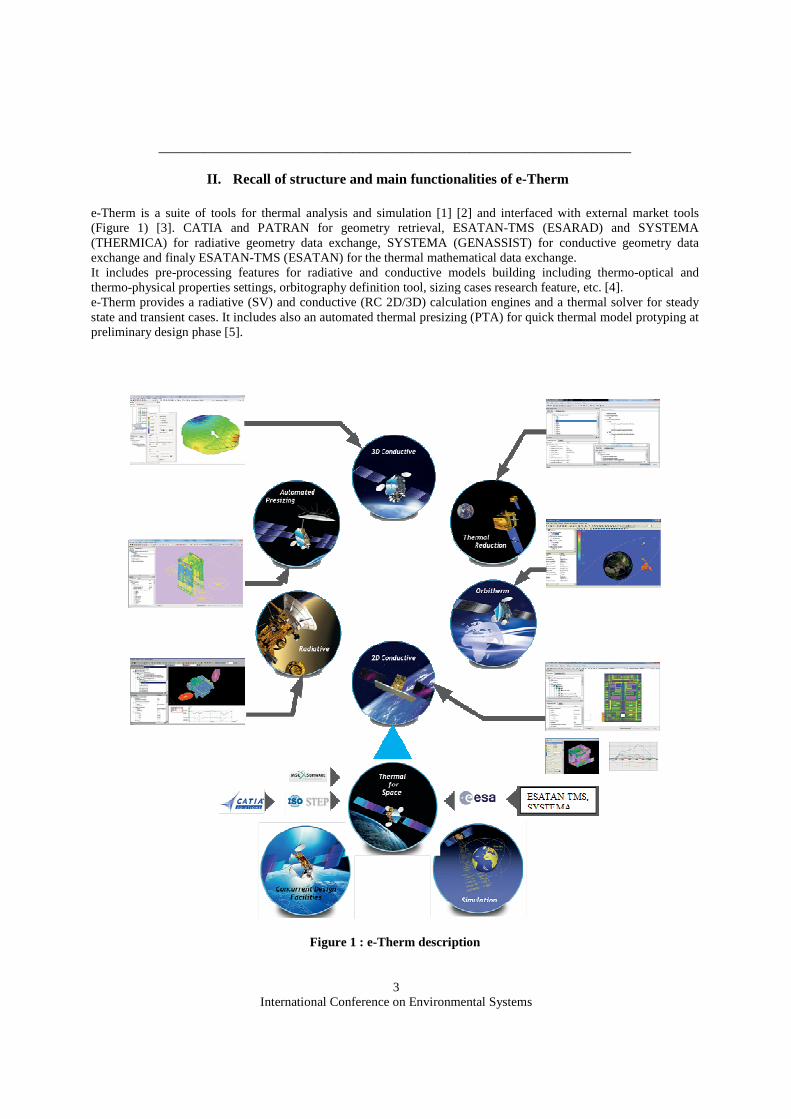
e-Therm is a suite of tools for thermal analysis and simulation [1] [2] and interfaced with external market tools (Figure 1) [3]. CATIA and PATRAN for geometry retrieval, ESATAN-TMS (ESARAD) and SYSTEMA (THERMICA) for radiative geometry data exchange, SYSTEMA (GENASSIST) for conductive geometry data exchange and finaly ESATAN-TMS (ESATAN) for the thermal mathematical data exchange. It includes pre-processing features for radiative and conductive models building including thermo-optical and thermo-physical properties settings, orbitography definition tool, sizing cases research feature, etc. [4]. e-Therm provides a radiative (SV) and conductive (RC 2D/3D) calculation engines and a thermal solver for steady state and transient cases. It includes also an automated thermal presizing (PTA) for quick thermal model protyping at preliminary design phase [5].
Figure 1 : e-Therm description

International Conference on Environmental Systems
4
e-Therm includes a thermal model reduction functionality especially designed to reduce models built from e-Therm but also from external tools such as SYSTEMA (THERMISOL) and ESATAN-TMS (ESATAN) [6] [9]. The tool includes a suite of post-processing modules to compute statistical data, temperatures recovery (from reduced models) and analysis. It provides also various plotting features with integrated temperatures comparison, specific heat transfer characteristics plots, 2D curves of powers and a dedicated graph viewer for embedded heatpipes transported powers. Graphs may be generated from results format and/or excel sheets. The SW provides a 3D view post-processing able to display a temperature cartography on thermal nodes and on vertices (3D conductive calculation). This feature is coupled with an animation engine able to display transient temperatures evolution over the time [7] [8]. e-Therm runs on Windows operating systems with the capability to launch all calculations on both local platform (Windows) but also on dedicated server on Linux platform. On Linux, the option is available to run cases in interactive or in batch mode. Runs may be started at a given time or in sequential or parallel modes. ________________________________________________________________________________________
III. TMRT: Methodology, rules and guidelines
III.1 Presentation
e-Therm provides a session for thermal mathematical model reduction. The reduction method is based on Thales Alenia Space Equival method for the supply of launcher thermal model and real-time simulator model. This tool is compatible with ESATAN format (including SYSTEMA), see methodology on figure 2. The session allows the user to define nodes groups, designing the list of kept nodes, the list of averaged nodes and the list of eliminated nodes. e-Therm facilitates the reduction model description avoiding mistakes when grouping a significant number of nodes of the detailed model. The reduction of conductive couplings is based on the Equival method (already used for instrumented panels when designing the detailed model), the reduction of the radiative part is simplified as a summation of the radiative couplings, the reduction of powers is performed thanks to a redistribution of eliminated powered nodes on kept nodes, the reduction of capacitances is performed either by a summation or a redistribution based on Equival method. The detailed nodes grouping may be weighted either by the capacitances or the nodes area. This module allows the user to perform a temperature recovery from the reduced model based on the eliminated nodes. This feature provides the capability to estimate the reduced model validity by comparing the recovered temperatures with the detailed original ones. For instance, a reduction by a factor ten of the detailed model may introduce a bias of 1 or 2 °C.
Equival method has been used and validated from years through lot of TBT on numerous internal TAS programs.
TMRT has been initially developed in the frame of collaboration between TAS, ADS, ESA and CNES. Then, improvements have been implemented by TAS, and the tool is systematically used on projects where a S/C reduced model is required by launcher authority for coupled analysis.

International Conference on Environmental Systems
5
Figure 2 : TMRT methodology with ESATAN-TMS DTMM re duction
III.2 Definition
Issued to EQUIVALE method, we define different kind of thermal nodes which can be involved in thermal equations :
1. Kept Node (K): it is a thermal node (assumed to be an isothermal one) which is used in detailed model and also used in reduced model.
2. Recomputed Eliminated Node (RE): it is a thermal node (assumed to be an isothermal one) which is used in detailed model but no more used in reduced model. However relations between RE and reduced model
International Conference on Environmental Systems
6
nodes allow to compute RE temperature. Those DTMM nodes can be Ti or Tj nodes. Those nodes do not appear in the RTMM and are related to RTMM nodes (temperature computation allowed).
Note: this node can have zero or non-zero radiative power and zero or non-zero internal power.
3. Fully Eliminated Node (FE): it is a thermal node (assumed to be an isothermal one) which exists in the detailed model but not in the reduced model. There are no relation between FE and reduced model nodes (temperature computation not allowed). Those DTMM nodes, which must have zero internal power, can be Ti or Tj nodes, according subchapter IV.1. notations. They do not appear in the RTMM and are not related to RTMM nodes (temperature computation not allowed).
Note: FE node can have zero radiative power (i.e. not connected with radiative surfaces) but must have zero internal power.
4. Average or Grouped Node (Av): it is a thermal node (also called “condensed node”), which is a function of temperature of some selected set of RE or FE. The Average node is not an isothermal one. It appears in the reduced model in order to simulate the thermal behaviour of a set of eliminated nodes RE and FE (reduction process). We say that these eliminated nodes “are related” to the Average node.
Note: if an isothermal eliminated node (RE or FE) has non zero radiative power, it must be related to an Av.
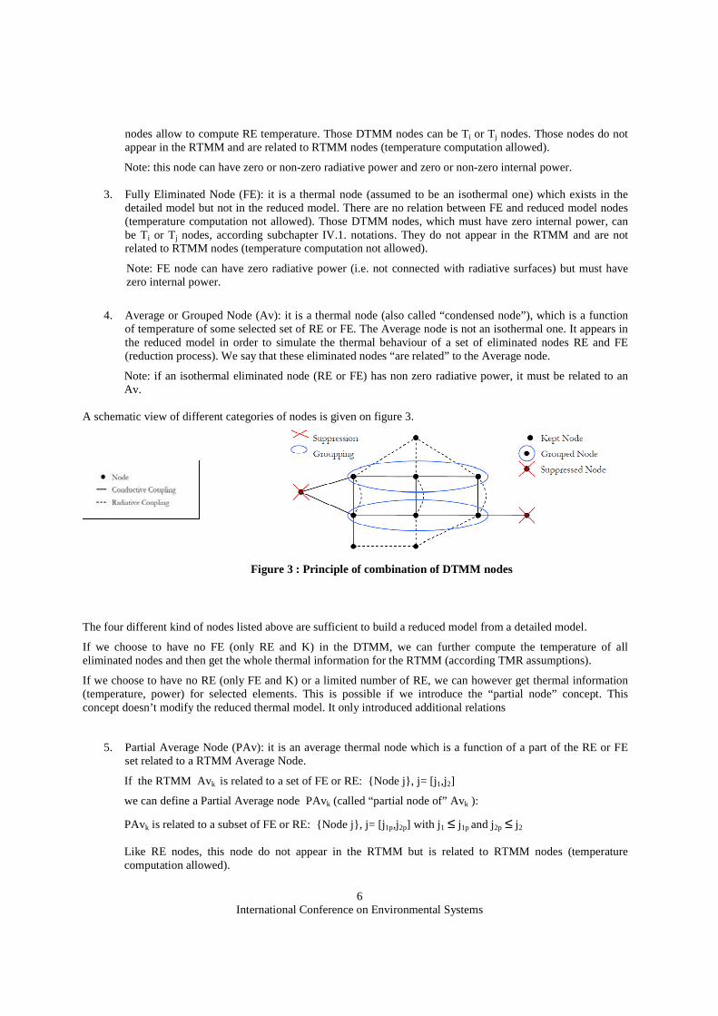
A schematic view of different categories of nodes is given on figure 3.
Figure 3 : Principle of combination of DTMM nodes
The four different kind of nodes listed above are sufficient to build a reduced model from a detailed model.
If we choose to have no FE (only RE and K) in the DTMM, we can further compute the temperature of all eliminated nodes and then get the whole thermal information for the RTMM (according TMR assumptions).
If we choose to have no RE (only FE and K) or a limited number of RE, we can however get thermal information (temperature, power) for selected elements. This is possible if we introduce the “partial node” concept. This concept doesn’t modify the reduced thermal model. It only introduced additional relations
5. Partial Average Node (PAv): it is an average thermal node which is a function of a part of the RE or FE set related to a RTMM Average Node.
If the RTMM Avk is related to a set of FE or RE: {Node j}, j= [j1,j2]
we can define a Partial Average node PAvk (called “partial node of” Avk ):
PAvk is related to a subset of FE or RE: {Node j}, j= [j1p,j2p] with j1 ≤ j1p and j2p ≤ j2
Like RE nodes, this node do not appear in the RTMM but is related to RTMM nodes (temperature computation allowed).

International Conference on Environmental Systems
7
The use of these nodes allows to get local (i.e. for j= j1p,j2p ) temperature information without computing temperature of the whole set of FE or RE (i.e.{Node j}, j= j1,j2)
6. Partial Kept Node (PK) or Partial Eliminated Node (PE): it is possible to formally split an isothermal node into virtual isothermal nodes. These “partial” nodes have, of course, the same temperature but have different power balance with the set of nodes connected to them. This virtual splitting allows to compute partial power balance without computing the temperature of all involved nodes.
Like RE nodes, these nodes do not appear in the RTMM but are related to RTMM nodes (power computation allowed).
III.3 Temrec and Puiequ modules
To reduce a model and compute temperature for eliminated nodes, different modules are used :
• EQUIVALE module is fully integrated in the e-Therm conductive module. It is the core of the conductive model reduction process.
• PUIEQU provides internal power redistribution (in relation with eliminated nodes dissipation). It is directly integrated into e-Therm solver. This module computes temperature for eliminated nodes using files generated by RC. For storage convenience, only steady state temperature of eliminated nodes is performed. PUIEQ module uses “Puieq” part of the matrix showed in eq. 5, section IV.4.
• TEMREC module allows to compute temperature of eliminated nodes for steady and transient states. Internal power dissipation of eliminated nodes must be time independent. Only on/off thermostat time dependent status is taken into account. TEMREC module uses “Matrec” and “Mat* rec” part of the matrix showed in eq. 5, section IV.4.
________________________________________________________________________________________
IV. Theoretical principle of TMRT
IV.1 Main preliminary equations The heat transfer equation for a given node n is written in a linear manner, as following
0)).(,( =+−∑≠
nnnm
m PTTmnC (eq. 1)
The average temperature of the “k” node is defined proportionally to the areas and so, proportionally to the capacitance.
The main assumption of the reduction is that condensed nodes shall have fluxes, radiative exchanges proportional to the areas.
P represents the fluxes, radiative exchanges, capacitances proportional to surface, heating power or dissipation.
After several steps, the new conductance matrix to be solved is equal to:
[ ]mlmmlmllllred DDDDMC 1−−== with
International Conference on Environmental Systems
8
=
−=
=
=
0
0
0
0
00
0
jm
ijlm
kj
jkjj
mmii
ll
QP
I
CD
a
aCD
CD
(eq. 2)
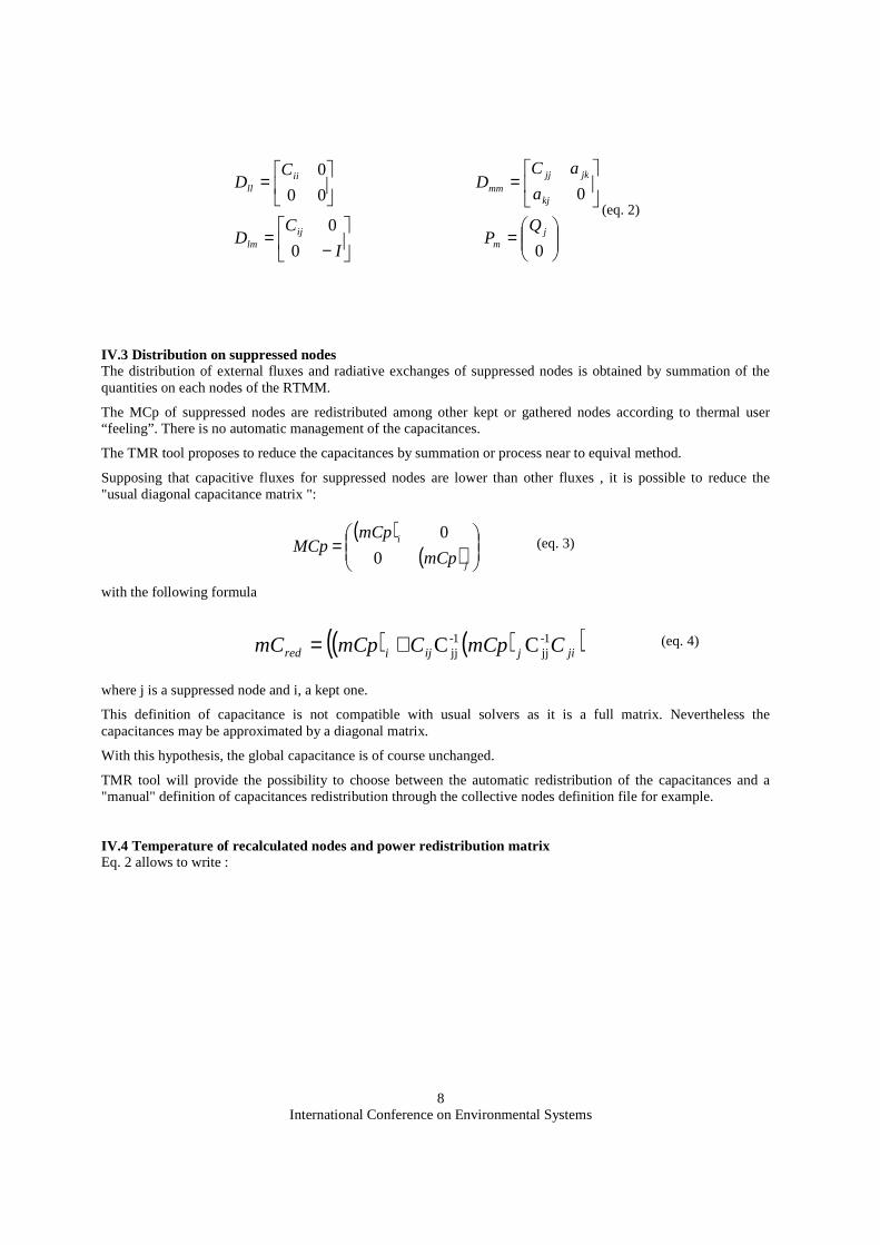
IV.3 Distribution on suppressed nodes The distribution of external fluxes and radiative exchanges of suppressed nodes is obtained by summation of the quantities on each nodes of the RTMM.
The MCp of suppressed nodes are redistributed among other kept or gathered nodes according to thermal user “feeling”. There is no automatic management of the capacitances.
The TMR tool proposes to reduce the capacitances by summation or process near to equival method.
Supposing that capacitive fluxes for suppressed nodes are lower than other fluxes , it is possible to reduce the "usual diagonal capacitance matrix ":
(eq. 3)
with the following formula
(eq. 4)
where j is a suppressed node and i, a kept one.
This definition of capacitance is not compatible with usual solvers as it is a full matrix. Nevertheless the capacitances may be approximated by a diagonal matrix.
With this hypothesis, the global capacitance is of course unchanged.
TMR tool will provide the possibility to choose between the automatic redistribution of the capacitances and a "manual" definition of capacitances redistribution through the collective nodes definition file for example.
IV.4 Temperature of recalculated nodes and power redistribution matrix Eq. 2 allows to write :
( )( )
=
j
i
mCp
mCpMCp
0
0
( ) ( )( )jijijired CmCpCmCpmC 1-jj
1-jj CC+=

International Conference on Environmental Systems
9
−
=
−
−
irecrec
eqeq
rec P
TTou
MatMat
PuiB
T
P
*
*
(eq. 5)
where
o Cred is identified as the RTMM conductive matrix,
o Puieq is identified as the power redistribution matrix (matrix which allows to compute the RTMM internal power vector ),
o Mat rec is identified as the matrix which allows to compute the temperature of eliminated nodes (RE),
IV.5 Particular nodes : « partial » nodes These particular nodes allow to calculate a local information without increasing the initial thermal model :
• Temperature for an average node
• Conductive power for an isothermal node
So these particular nodes are recalculated nodes. Applications linked to the using of this functionality are multiple : thermo-elastic treatment drawing a temperature cartography on the mechanical model (EF method), power delivered treatment by a heat-pipe, correlation …
IV.6 Restitution Average Nodes (RA nodes) : These nodes are specific ones which are neither in the DTMM nor in the RTMM, and defined as groups of nodes from the DTMM. They provide the average temperature of groups of nodes from the DTMM. This information of temperature is accessible only through the temperature recovery process.
They are necessary geometrical.
For example, if we consider node 2 like the restitution average of node 1 and node 2’ like the geometrical sum of node 1 and node 2, the relations governing RA node are :
21'2 φφφ ==
2211'
2 TaTaTA += with 21 aaA +=
Equal to D-1mm matrix if it is completed by 0 on the missing quarter matrix
2 RA Node
1 Average Node
2’ Kept Node
International Conference on Environmental Systems
10
These restitution average nodes have, of course, the same flux but have different temperature with the set of nodes connected to them. This fictive splitting allows to compute a local temperature.
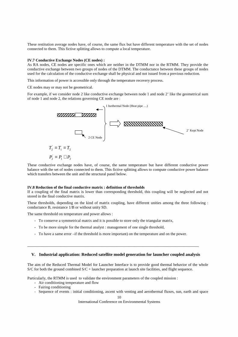
IV.7 Conductive Exchange Nodes (CE nodes) : As RA nodes, CE nodes are specific ones which are neither in the DTMM nor in the RTMM. They provide the conductive exchange between two groups of nodes of the DTMM. The conductance between these groups of nodes used for the calculation of the conductive exchange shall be physical and not issued from a previous reduction.
This information of power is accessible only through the temperature recovery process.
CE nodes may or may not be geometrical.
For example, if we consider node 2 like conductive exchange between node 1 and node 2’ like the geometrical sum of node 1 and node 2, the relations governing CE node are :
21'
2 TTT ==
21'
2 PPP +=
These conductive exchange nodes have, of course, the same temperature but have different conductive power balance with the set of nodes connected to them. This fictive splitting allows to compute conductive power balance which transfers between the unit and the structural panel below.
IV.8 Reduction of the final conductive matrix : definition of thresholds If a coupling of the final matrix is lower than corresponding threshold, this coupling will be neglected and not stored in the final conductive matrix.
These thresholds, depending on the kind of matrix coupling, have different unities among the three following : conductance B, resistance 1/B or without unity SD.
The same threshold on temperature and power allows :
- To conserve a symmetrical matrix and it is possible to store only the triangular matrix,
- To be more simple for the thermal analyst : management of one single threshold,
- To have a same error –if the threshold is more important) on the temperature and on the power.
________________________________________________________________________________________
V. Industrial application: Reduced satellite model generation for launcher coupled analysis The aim of the Reduced Thermal Model for Launcher Interface is to provide good thermal behavior of the whole S/C for both the ground combined S/C + launcher preparation at launch site facilities, and flight sequence. Particularly, the RTMM is used to validate the environment parameters of the coupled mission :
- Air conditioning temperature and flow - Fairing conditioning - Sequence of events : initial conditioning, ascent with venting and aerothermal fluxes, sun, earth and space
2 CE Node
1 Isothermal Node (Heat pipe …)
2’ Kept Node

International Conference on Environmental Systems
11
environment, timing,
V.1 Telecom S/C case The example given in this paragraph is a 4000C4 Telecom S/C. The TMM/GMM have been built with eTherm 1.7, and the reduction has been processed using MCp as averaging parameter. V.1.1 Specification The lowest value of maximum allowed thermal nodes number among all launcher agencies being 400, this target is always taken as the basic objective to take into account multi-launcher compatibility and consistency between different application programs. In order to guarantee the representativeness of the thermal behavior and the management of the coupled-analyses, the targeted reduction completion criteria is declined on the basis of temperature discrepancy between DTMM and RTMM nodes limited to :
- Less than 2°C on critical units (avionics, propulsion, battery, TCR…) - Less than 5°C on non-critical units and structure nodes - Less than 10°C on MLI nodes
This criteria applies on both minimum and maximum temperatures experienced during a standard transient phase : - S/C alone in Space environment (no launcher influence) - Initial Temperature at 20°C - S/C spin along +Z axis - Sun exposure with a constant angle (< 90°) wrt +Z axis, generating transient sun fluxes on all panels and
items excepts –Z thanks to S/C spin The following figure illustrates these environmental conditions
Figure 4 : Environmental conditions for RTMM/DTMM v alidation
V.1.2 Reduction Synthesis The reduction process enables to go from 2873 node for the DTMM down to 323 nodes for the RTMM shared as : - 85 nodes for critical units - 180 nodes for non-critical units and structure nodes - 58 nodes for MLI nodes The temperature performance of the Reduction (fulfillment of the discrepancy criteria) is summarized in the following table :
ITEMS MINIMUM TEMPERATURE
MAXIMUM TEMPERATURE
Critical units (| ∆∆∆∆T| < 2°C) 93% 79% Non critical units & structure (| ∆∆∆∆T| < 5°C) 89% 93% MLI (| ∆∆∆∆T| < 10°C) 86% 86%
+Z
ωωωω
International Conference on Environmental Systems
12
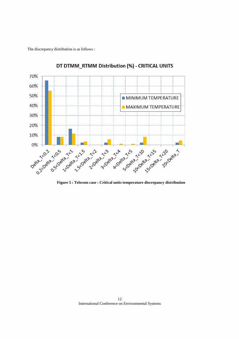
The discrepancy distribution is as follows :
Figure 5 : Telecom case : Critical units temperature discrepancy distribution

International Conference on Environmental Systems
13
Figure 6 : Telecom case : Non critical units and structure temperature discrepancy distribution
Figure 7 : Telecom case : MLI nodes temperature discrepancy distribution
The RTMM fulfils the requirements and has been delivered to launcher agency that agreed the discrepancy criteria
International Conference on Environmental Systems
14
(percentage of nodes that fulfil the requirements done on dedicated table above). Concerning the few nodes which are over the requirements that can be observed on figures 5, 6 and 7, the status is the following:
- These nodes correspond with non critical areas / units, - The allowables temperatures given in the requirement documentation to launcher authority have been
corrected by the observed discrepancy between RTMM and DTMM.
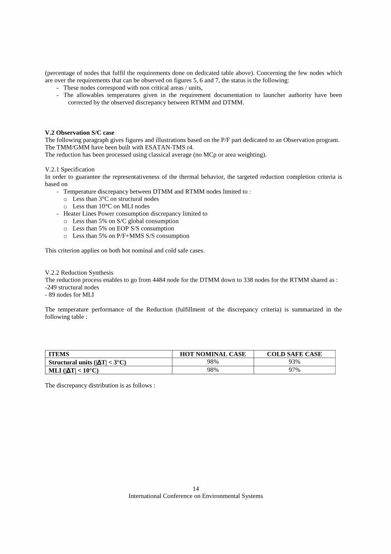
V.2 Observation S/C case The following paragraph gives figures and illustrations based on the P/F part dedicated to an Observation program. The TMM/GMM have been built with ESATAN-TMS r4. The reduction has been processed using classical average (no MCp or area weighting). V.2.1 Specification In order to guarantee the representativeness of the thermal behavior, the targeted reduction completion criteria is based on
- Temperature discrepancy between DTMM and RTMM nodes limited to : o Less than 3°C on structural nodes o Less than 10°C on MLI nodes
- Heater Lines Power consumption discrepancy limited to o Less than 5% on S/C global consumption o Less than 5% on EOP S/S consumption o Less than 5% on P/F+MMS S/S consumption
This criterion applies on both hot nominal and cold safe cases. V.2.2 Reduction Synthesis The reduction process enables to go from 4484 node for the DTMM down to 338 nodes for the RTMM shared as : -249 structural nodes - 89 nodes for MLI The temperature performance of the Reduction (fulfillment of the discrepancy criteria) is summarized in the following table :
ITEMS HOT NOMINAL CASE COLD SAFE CASE Structural units (|∆∆∆∆T| < 3°C) 98% 93% MLI (| ∆∆∆∆T| < 10°C) 98% 97%
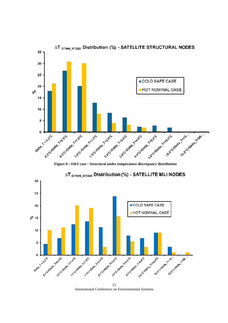
The discrepancy distribution is as follows :
International Conference on Environmental Systems
15
Figure 8 : O&S case : Structural nodes temperature discrepancy distribution
International Conference on Environmental Systems
16
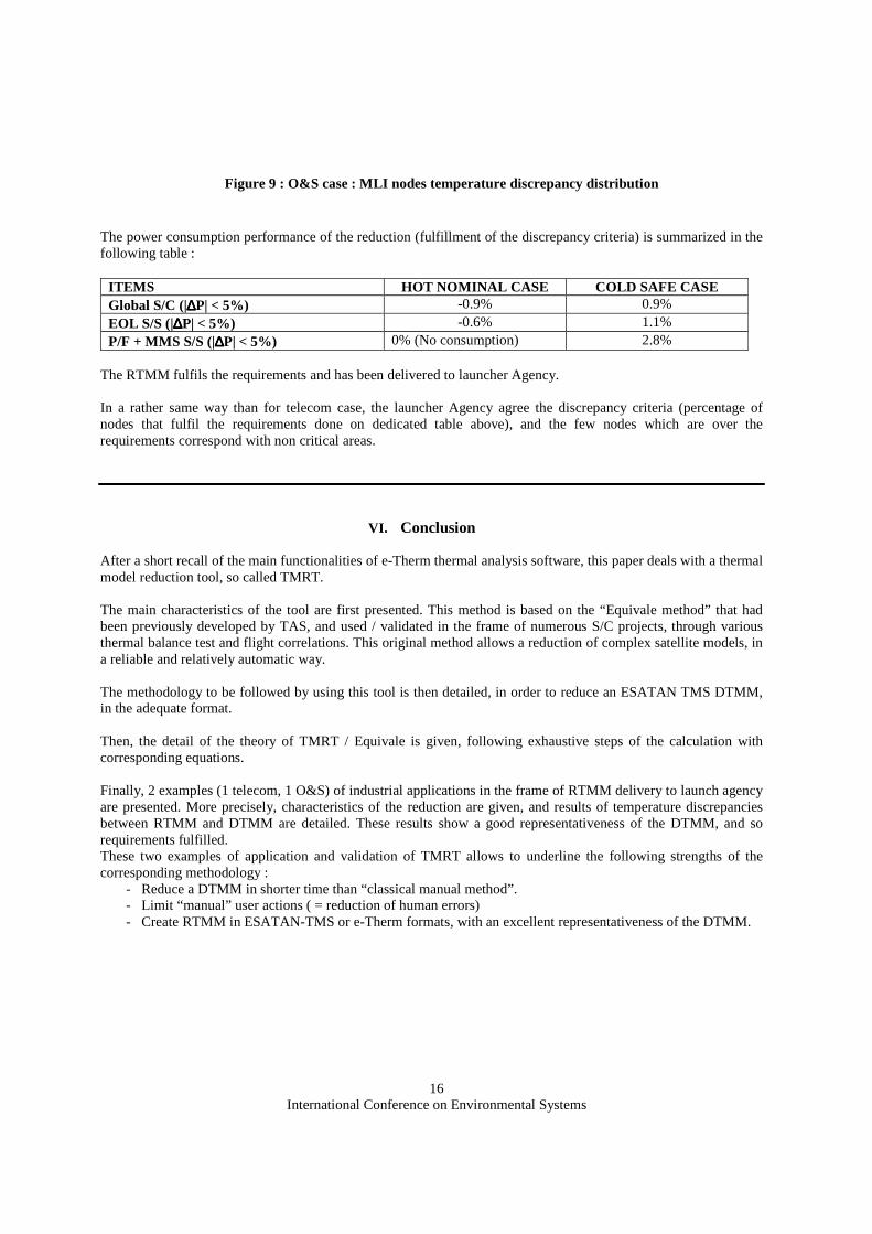
Figure 9 : O&S case : MLI nodes temperature discrepancy distribution The power consumption performance of the reduction (fulfillment of the discrepancy criteria) is summarized in the following table :
ITEMS HOT NOMINAL CASE COLD SAFE CASE Global S/C (|∆∆∆∆P| < 5%) -0.9% 0.9% EOL S/S (|∆∆∆∆P| < 5%) -0.6% 1.1% P/F + MMS S/S (|∆∆∆∆P| < 5%) 0% (No consumption) 2.8%
The RTMM fulfils the requirements and has been delivered to launcher Agency. In a rather same way than for telecom case, the launcher Agency agree the discrepancy criteria (percentage of nodes that fulfil the requirements done on dedicated table above), and the few nodes which are over the requirements correspond with non critical areas.
VI. Conclusion After a short recall of the main functionalities of e-Therm thermal analysis software, this paper deals with a thermal model reduction tool, so called TMRT. The main characteristics of the tool are first presented. This method is based on the “Equivale method” that had been previously developed by TAS, and used / validated in the frame of numerous S/C projects, through various thermal balance test and flight correlations. This original method allows a reduction of complex satellite models, in a reliable and relatively automatic way. The methodology to be followed by using this tool is then detailed, in order to reduce an ESATAN TMS DTMM, in the adequate format. Then, the detail of the theory of TMRT / Equivale is given, following exhaustive steps of the calculation with corresponding equations. Finally, 2 examples (1 telecom, 1 O&S) of industrial applications in the frame of RTMM delivery to launch agency are presented. More precisely, characteristics of the reduction are given, and results of temperature discrepancies between RTMM and DTMM are detailed. These results show a good representativeness of the DTMM, and so requirements fulfilled. These two examples of application and validation of TMRT allows to underline the following strengths of the corresponding methodology :
- Reduce a DTMM in shorter time than “classical manual method”. - Limit “manual” user actions ( = reduction of human errors) - Create RTMM in ESATAN-TMS or e-Therm formats, with an excellent representativeness of the DTMM.

International Conference on Environmental Systems
17
________________________________________________________________________________________
References
• 1 “e-Therm policy”, 26th Thermal and ECLS Software Workshop (2013), Basset, Hugonnot. • 2 “TAS thermal software suite : presentation of the tools and current policy”, 22nd Thermal and ECLS
Software Workshop (2009), Basset. • 3 “Interface between STEP-TAS format and Alcatel Space’s CIGAL2 application”, 18th Thermal and ECLS
Software Workshop (2004), Caillet, Basset, Salançon. • 4 “e-therm : New release”, 25th Thermal and ECLS Software Workshop (2012), Basset, Connil, Brunetti. • 5 “e-Therm : An integrated thermal analysis tool for Thales Alenia Space”, 40th International conference of
Environmental Systems ICES (2010), Basset, Dudon, Brunetti. • 6 “Thermal Model Reduction – theory & Application”, 40th International conference of Environmental
Systems AIAA-ICES (2010), Bernard, Basset, Etchells, Brunetti • 7 “3D conductive module”, 20th Thermal and ECLS Software Workshop (2006), Basset, Dudon • 8 “A new method for 3D thermal modelling with Coratherm”, 33rd International conference of Environmental
Systems ICES (2003), Dudon, Basset, Peyrard. • 9 “TMRT (Thermal Model Reduction Tool), application on ESATAN-TMS detailed thermal mathematical
model”, ESA 28th European Space Thermal Analysis Workshop (2014), Ferrier, Valentini.