tms 2012
TRANSCRIPT

On the Factors Governing the Sink Strength of Semicoherent fcc-bcc Interfaces
Kedarnath Kolluri and Michael Demkowicz
Financial Support:
Center for Materials at Irradiation and Mechanical Extremes (CMIME) at LANL,
an Energy Frontier Research Center (EFRC) funded by
U.S. Department of Energy, Office of Science, Office of Basic Energy Sciences
Acknowledgments: B. P. Uberuaga, A. Kashinath, A. Vattré, X.-Y. Liu, A. Misra, R. G. Hoagland, J. P. Hirth, M. A. Nastasi, and A. Caro

• Point defects (lets assume the cascade occurs in bulk)
• arrive at the interface
• reside and move at coherent regions of the interface until either
• emit back into the bulk
• embed into “non coherent” regions of the interface
• dynamics of embedded defects
Predicting interface sink efficiency: Beyond v.1
Cartoon of defect activity in radiation environment
l2bDb
eff
⌫e��E/kT
Ac
Diceff
l2bDb
eff
Ac
Diceff

• Point defects (lets assume the cascade occurs in bulk)
• arrive at the interface
• reside and move at coherent regions of the interface until either
• emit back into the bulk
• embed into “non coherent” regions of the interface
• dynamics of embedded defects UNKNOWN
Cartoon of defect activity in radiation environment
l2bDb
eff
⌫e��E/kT
Ac
Diceff
l2bDb
eff
Ac
Diceff
Predicting interface sink efficiency: Beyond v.1
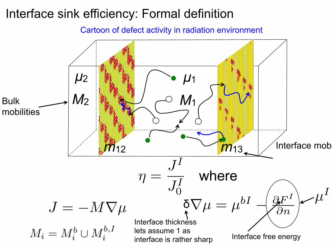
Interface sink efficiency: Formal definitionCartoon of defect activity in radiation environment
where
M2
µ2
M1
µ1
m13m12
⌘ =JI
JI0
Mi = M bi [M b,I
i
Bulk mobilities
Interface mobilities
Interface free energy
µI
J = �Mrµ rµ = µbI � @F I
@nδ
Interface thickness lets assume 1 as interface is rather sharp
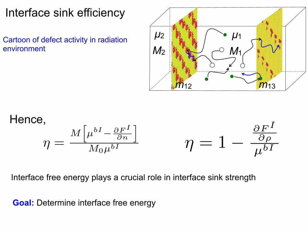
Interface sink efficiency
Cartoon of defect activity in radiation environment
Hence,
Interface free energy plays a crucial role in interface sink strength
Goal: Determine interface free energy
⌘ =M
hµbI� @FI
@n
i
M0µbI ⌘ = 1�@FI
@⇢
µbI
M2
µ2M1
µ1M3
µ3
m13m12

Interface structure evolves
Schematic of free energy of an interface
★ Interface structure evolves as defects interact with the interface
Inte
rface
ene
rgy
(f)
Interfacial density (ρ)
voidphase transformation
structure evolvesf(⇢, . . . )
⌘ = 1�@FI
@⇢
µbI
F I ⌘ �(f(⇢, . . . ),Mi,m)

★ Different interface regions may have different densities
★ Different density region have different free energies
Interface sink efficiency change as structure evolves
Interfacial density (ρ)
Inte
rface
ene
rgy
(f)
µvbulk
µibulk
voidphase transformation
structure evolves
f(⇢, . . . )
F I ⌘ �(f(⇢, . . . ),Mi,m)
⌘ = 1�@FI
@⇢
µbI
M2
µ2M1
µ1M3
µ3
m13m12

Holy grail: Predict sink efficiency as interface structure evolves
Schematic of interface free energyPoint defect activity under radiation
Interfacial density (ρ)
Inte
rface
ene
rgy
(f)
µvbulk
µibulk
voidphase transformation
structure evolves
f(⇢, . . . )
F I ⌘ �(f(⇢, . . . ),Mi,m)
Goal: To determine in the context of interface structure
• Interface free energy (factors that determine the energy functional)
• Point defect mobilities that will determine the interface evolution
⌘(t) = 1�@FI
@⇢
µbI
M2
µ2M1
µ1M3
µ3
m13m12

• Our focus is on
• interfaces of immiscible fcc-bcc semicoherent metal systems
Cu-Nb, Cu-V, Cu-Mo, Cu-Fe, and Ag-V (in both KS and NW)
Methods and model systems
• Atomistic simulations of few interfaces:
Molecular dynamics (at 800 K) and statics, EAM potential, LAMMPS
• Develop insights that may be used to develop figures of merits for
classes of interfaces
(111) fcc(110)
bcc|| 〈110〉
fcc〈111〉
bcc||andKurdjumov-Sachs (KS):
(111) fcc(110)
bcc|| 〈110〉
fcc〈100〉
bcc||andNishiyama-Wassermann (NW):
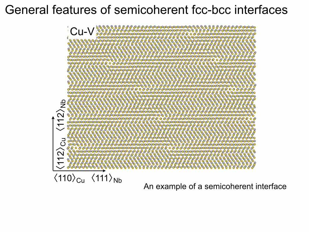
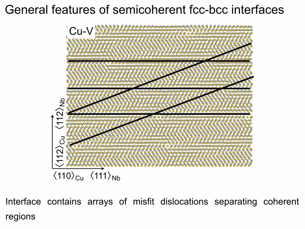
General features of semicoherent fcc-bcc interfaces
Cu-V
〈110〉Cu〈111〉Nb
〈112〉 Cu〈112〉 Nb
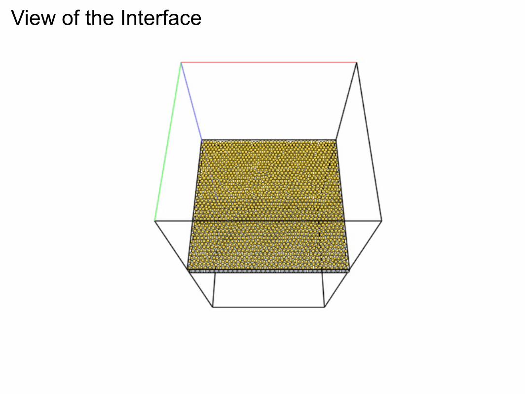
An example of a semicoherent interface

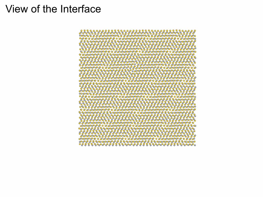
View of the Interface

View of the Interface
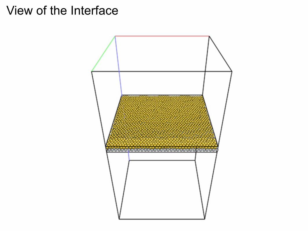
View of the Interface
View of the Interface

View of the Interface
View of the Interface

General features of semicoherent fcc-bcc interfaces
Cu-V
〈110〉Cu〈111〉Nb
〈112〉 Cu〈112〉 Nb
An example of a fcc-bcc semicoherent interface
Patterns corresponding to periodic “good” and “bad” regions
General features of semicoherent fcc-bcc interfaces
Cu-V
〈110〉Cu〈111〉Nb
〈112〉 Cu〈112〉 Nb
Interface contains arrays of misfit dislocations separating coherent regions

General features of semicoherent fcc-bcc interfaces
〈110〉Cu〈111〉Nb
〈11
2〉C
u〈
112〉
Nb
Cu-Nb Cu-V
Interface contains arrays of misfit dislocations separating coherent regions

Cu-Nb KS Cu-V KS〈110〉Cu
〈11
2〉C
u1 nm
MDI
• Two sets of misfit dislocations with Burgers vectors
• Misfit dislocation intersections (MDI) where different sets of dislocations meet
General features of semicoherent fcc-bcc interfaces

Defects on misfit dislocations are good traps to point defects
0
0
0.2
0.4
0.6
0.8
1
0 0.2 0.4 0.6 0.8 1
0
50
100
150
0
0.2
0.4
0.6
0.8
1
0 0.2 0.4 0.6 0.8 1
0.15
0.2
0.25
0.3
0.35
0.4
0.45
0.5
0
0
0.2
0.4
0.6
0.8
1
0 0.2 0.4 0.6 0.8 1
0
50
100
150
0
0.2
0.4
0.6
0.8
1
0 0.2 0.4 0.6 0.8 1
0.05
0.1
0.15
0.2
0.25
0.3
0.35
0.4
0.45
0.5
0.55
Cu-Nb KS Cu-Fe NW Cu-V KS
1 nm
0
0
0.2
0.4
0.6
0.8
1
0 0.2 0.4 0.6 0.8 1
0
50
100
150
0
0.2
0.4
0.6
0.8
1
0 0.2 0.4 0.6 0.8 1
0.06
0.08
0.1
0.12
0.14
0.16
0.18
0.2
0.22
0.24
0.26
0.28
0
0.2
0.4
0.6
0.8
1
0 0.2 0.4 0.6 0.8 1
0.6
0.8
1
1.2
1.4
0
0.2
0.4
0.6
0.8
1
0 0.2 0.4 0.6 0.8 1
0.6
0.8
1
1.2
1.4
0
0.2
0.4
0.6
0.8
1
0 0.2 0.4 0.6 0.8 1
0.6
0.8
1
1.2
1.4
1 nm 1.4 nm
Form
atio
n en
ergy
(eV
)A
ngle
with
-ve
x ax
is
0
0
0.2
0.4
0.6
0.8
1
0 0.2 0.4 0.6 0.8 1
0
50
100
150
0
0.2
0.4
0.6
0.8
1
0 0.2 0.4 0.6 0.8 1
0.15
0.2
0.25
0.3
0.35
0.4
0.45
0.5
0
0
0.2
0.4
0.6
0.8
1
0 0.2 0.4 0.6 0.8 1
0
50
100
150
0
0.2
0.4
0.6
0.8
1
0 0.2 0.4 0.6 0.8 1
0.05
0.1
0.15
0.2
0.25
0.3
0.35
0.4
0.45
0.5
0.55
Cu-Nb KS Cu-Fe NW Cu-V KS
1 nm
0
0
0.2
0.4
0.6
0.8
1
0 0.2 0.4 0.6 0.8 1
0
50
100
150
0
0.2
0.4
0.6
0.8
1
0 0.2 0.4 0.6 0.8 1
0.06
0.08
0.1
0.12
0.14
0.16
0.18
0.2
0.22
0.24
0.26
0.28
0
0.2
0.4
0.6
0.8
1
0 0.2 0.4 0.6 0.8 1
0.6
0.8
1
1.2
1.4
0
0.2
0.4
0.6
0.8
1
0 0.2 0.4 0.6 0.8 1
0.6
0.8
1
1.2
1.4
0
0.2
0.4
0.6
0.8
1
0 0.2 0.4 0.6 0.8 1
0.6
0.8
1
1.2
1.4
1 nm 1.4 nm
Form
atio
n en
ergy
(eV
)A
ngle
with
-ve
x ax
is
Different fcc-bcc semicoherent interfaces with misfit dislocations
Vacancy formation energies (similar trend for interstitials as well)

Interface reconstruction dominated by MDI-point defect interactions
Interface structure evolution depends on MDI interactions with point defects
Form
atio
n en
ergy
(eV
)
Ag-V NW
Cu-Nb KS
Size of point defect cluster at an MDI
-1
-0.5
0
0.5
1
1.5
2
2.5
3
3.5
-10 -8 -6 -4 -2 0 2 4 6 8 10
Cu-Mo KS
B CA

Interface reconstruction dominated by MDI-point defect interactions
Interface structure evolution depends onMDI interactions with point defects
Form
atio
n en
ergy
(eV
)
Ag-V NW
Cu-Nb KS
Size of point defect cluster at an MDI
-1
-0.5
0
0.5
1
1.5
2
2.5
3
3.5
-10 -8 -6 -4 -2 0 2 4 6 8 10
Cu-Mo KS
B CA
B’A’
Cu-Nb

A’ B’
Cu-Mo
Interface structure evolution depends on MDI interactions with point defects
Interface reconstruction dominated by MDI-point defect interactionsFo
rmat
ion
ener
gy (e
V)
Ag-V NW
Cu-Nb KS
Size of point defect cluster at an MDI
-1
-0.5
0
0.5
1
1.5
2
2.5
3
3.5
-10 -8 -6 -4 -2 0 2 4 6 8 10
Cu-Mo KS
B CA
C’A’
Ag-V
Holy grail: Predict sink strength as interface structure evolves
Schematic interface free energyPoint defect activity under radiation
⌘ = 1�P
Mi@FI
@⇢PMiµI
i
Interfacial density (ρ)
Inte
rface
ene
rgy
(f)
µvbulk
µibulk
voidphase transformation
structure evolves
f(⇢, . . . )
M2
µ2M1
µ1M3
µ3
m13m12
F I ⌘ �(f(⇢, . . . ),Mi,m)
Goal: To determine
• Interface free energy (or factors)
• point defect mobilities that will determine the interface evolution
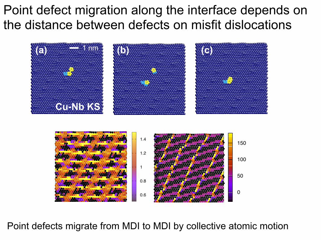
Point defect migration along the interface depends on the distance between defects on misfit dislocations
Point defects migrate from MDI to MDI by collective atomic motion
Cu-Nb KS
(a) (b) (c)1 nm
0
0
0.2
0.4
0.6
0.8
1
0 0.2 0.4 0.6 0.8 1
0
50
100
150
0
0.2
0.4
0.6
0.8
1
0 0.2 0.4 0.6 0.8 1
0.15
0.2
0.25
0.3
0.35
0.4
0.45
0.5
0
0
0.2
0.4
0.6
0.8
1
0 0.2 0.4 0.6 0.8 1
0
50
100
150
0
0.2
0.4
0.6
0.8
1
0 0.2 0.4 0.6 0.8 1
0.05
0.1
0.15
0.2
0.25
0.3
0.35
0.4
0.45
0.5
0.55
0
0
0.2
0.4
0.6
0.8
1
0 0.2 0.4 0.6 0.8 1
0
50
100
150
0
0.2
0.4
0.6
0.8
1
0 0.2 0.4 0.6 0.8 1
0.15
0.2
0.25
0.3
0.35
0.4
0.45
0.5
0
0
0.2
0.4
0.6
0.8
1
0 0.2 0.4 0.6 0.8 1
0
50
100
150
0
0.2
0.4
0.6
0.8
1
0 0.2 0.4 0.6 0.8 1
0.05
0.1
0.15
0.2
0.25
0.3
0.35
0.4
0.45
0.5
0.55
Cu-Nb KS Cu-Fe NW Cu-V KS
1 nm
0
0
0.2
0.4
0.6
0.8
1
0 0.2 0.4 0.6 0.8 1
0
50
100
150
0
0.2
0.4
0.6
0.8
1
0 0.2 0.4 0.6 0.8 1
0.06
0.08
0.1
0.12
0.14
0.16
0.18
0.2
0.22
0.24
0.26
0.28
0
0.2
0.4
0.6
0.8
1
0 0.2 0.4 0.6 0.8 1
0.6
0.8
1
1.2
1.4
0
0.2
0.4
0.6
0.8
1
0 0.2 0.4 0.6 0.8 1
0.6
0.8
1
1.2
1.4
0
0.2
0.4
0.6
0.8
1
0 0.2 0.4 0.6 0.8 1
0.6
0.8
1
1.2
1.4
1 nm 1.4 nm
Form
atio
n en
ergy
(eV
)A
ngle
with
-ve
x ax
is
0
0
0.2
0.4
0.6
0.8
1
0 0.2 0.4 0.6 0.8 1
0
50
100
150
0
0.2
0.4
0.6
0.8
1
0 0.2 0.4 0.6 0.8 1
0.15
0.2
0.25
0.3
0.35
0.4
0.45
0.5
0
0
0.2
0.4
0.6
0.8
1
0 0.2 0.4 0.6 0.8 1
0
50
100
150
0
0.2
0.4
0.6
0.8
1
0 0.2 0.4 0.6 0.8 1
0.05
0.1
0.15
0.2
0.25
0.3
0.35
0.4
0.45
0.5
0.55
Cu-Nb KS Cu-Fe NW Cu-V KS
1 nm
0
0
0.2
0.4
0.6
0.8
1
0 0.2 0.4 0.6 0.8 1
0
50
100
150
0
0.2
0.4
0.6
0.8
1
0 0.2 0.4 0.6 0.8 1
0.06
0.08
0.1
0.12
0.14
0.16
0.18
0.2
0.22
0.24
0.26
0.28
0
0.2
0.4
0.6
0.8
1
0 0.2 0.4 0.6 0.8 1
0.6
0.8
1
1.2
1.4
0
0.2
0.4
0.6
0.8
1
0 0.2 0.4 0.6 0.8 1
0.6
0.8
1
1.2
1.4
0
0.2
0.4
0.6
0.8
1
0 0.2 0.4 0.6 0.8 1
0.6
0.8
1
1.2
1.4
1 nm 1.4 nm
Form
atio
n en
ergy
(eV
)A
ngle
with
-ve
x ax
is

Point defect migration along the interface depends on the distance between defects on misfit dislocations
Point defects migrate from one dislocation defect to another by collective atomic motion
0
0
0.2
0.4
0.6
0.8
1
0 0.2 0.4 0.6 0.8 1
0
50
100
150
0
0.2
0.4
0.6
0.8
1
0 0.2 0.4 0.6 0.8 1
0.05
0.1
0.15
0.2
0.25
0.3
0.35
0.4
0.45
0.5
0.55
0
0
0.2
0.4
0.6
0.8
1
0 0.2 0.4 0.6 0.8 1
0
50
100
150
0
0.2
0.4
0.6
0.8
1
0 0.2 0.4 0.6 0.8 1
0.15
0.2
0.25
0.3
0.35
0.4
0.45
0.5
0
0
0.2
0.4
0.6
0.8
1
0 0.2 0.4 0.6 0.8 1
0
50
100
150
0
0.2
0.4
0.6
0.8
1
0 0.2 0.4 0.6 0.8 1
0.05
0.1
0.15
0.2
0.25
0.3
0.35
0.4
0.45
0.5
0.55
Cu-Nb KS Cu-Fe NW Cu-V KS
1 nm
0
0
0.2
0.4
0.6
0.8
1
0 0.2 0.4 0.6 0.8 1
0
50
100
150
0
0.2
0.4
0.6
0.8
1
0 0.2 0.4 0.6 0.8 1
0.06
0.08
0.1
0.12
0.14
0.16
0.18
0.2
0.22
0.24
0.26
0.28
0
0.2
0.4
0.6
0.8
1
0 0.2 0.4 0.6 0.8 1
0.6
0.8
1
1.2
1.4
0
0.2
0.4
0.6
0.8
1
0 0.2 0.4 0.6 0.8 1
0.6
0.8
1
1.2
1.4
0
0.2
0.4
0.6
0.8
1
0 0.2 0.4 0.6 0.8 1
0.6
0.8
1
1.2
1.4
1 nm 1.4 nm
Form
atio
n en
ergy
(eV
)A
ngle
with
-ve
x ax
is
1 nm
Cu-V KS
(a) (b) (c)

1 nm
Cu-Fe NW
Point defects migrate along misfit dislocation lines
0
0
0.2
0.4
0.6
0.8
1
0 0.2 0.4 0.6 0.8 1
0
50
100
150
0
0.2
0.4
0.6
0.8
1
0 0.2 0.4 0.6 0.8 1
0.06
0.08
0.1
0.12
0.14
0.16
0.18
0.2
0.22
0.24
0.26
0.28
0
0
0.2
0.4
0.6
0.8
1
0 0.2 0.4 0.6 0.8 1
0
50
100
150
0
0.2
0.4
0.6
0.8
1
0 0.2 0.4 0.6 0.8 1
0.05
0.1
0.15
0.2
0.25
0.3
0.35
0.4
0.45
0.5
0.55
0
0
0.2
0.4
0.6
0.8
1
0 0.2 0.4 0.6 0.8 1
0
50
100
150
0
0.2
0.4
0.6
0.8
1
0 0.2 0.4 0.6 0.8 1
0.15
0.2
0.25
0.3
0.35
0.4
0.45
0.5
0
0
0.2
0.4
0.6
0.8
1
0 0.2 0.4 0.6 0.8 1
0
50
100
150
0
0.2
0.4
0.6
0.8
1
0 0.2 0.4 0.6 0.8 1
0.05
0.1
0.15
0.2
0.25
0.3
0.35
0.4
0.45
0.5
0.55
Cu-Nb KS Cu-Fe NW Cu-V KS
1 nm
0
0
0.2
0.4
0.6
0.8
1
0 0.2 0.4 0.6 0.8 1
0
50
100
150
0
0.2
0.4
0.6
0.8
1
0 0.2 0.4 0.6 0.8 1
0.06
0.08
0.1
0.12
0.14
0.16
0.18
0.2
0.22
0.24
0.26
0.28
0
0.2
0.4
0.6
0.8
1
0 0.2 0.4 0.6 0.8 1
0.6
0.8
1
1.2
1.4
0
0.2
0.4
0.6
0.8
1
0 0.2 0.4 0.6 0.8 1
0.6
0.8
1
1.2
1.4
0
0.2
0.4
0.6
0.8
1
0 0.2 0.4 0.6 0.8 1
0.6
0.8
1
1.2
1.4
1 nm 1.4 nm
Form
atio
n en
ergy
(eV
)A
ngle
with
-ve
x ax
is
0
0
0.2
0.4
0.6
0.8
1
0 0.2 0.4 0.6 0.8 1
0
50
100
150
0
0.2
0.4
0.6
0.8
1
0 0.2 0.4 0.6 0.8 1
0.15
0.2
0.25
0.3
0.35
0.4
0.45
0.5
0
0
0.2
0.4
0.6
0.8
1
0 0.2 0.4 0.6 0.8 1
0
50
100
150
0
0.2
0.4
0.6
0.8
1
0 0.2 0.4 0.6 0.8 1
0.05
0.1
0.15
0.2
0.25
0.3
0.35
0.4
0.45
0.5
0.55
Cu-Nb KS Cu-Fe NW Cu-V KS
1 nm
0
0
0.2
0.4
0.6
0.8
1
0 0.2 0.4 0.6 0.8 1
0
50
100
150
0
0.2
0.4
0.6
0.8
1
0 0.2 0.4 0.6 0.8 1
0.06
0.08
0.1
0.12
0.14
0.16
0.18
0.2
0.22
0.24
0.26
0.28
0
0.2
0.4
0.6
0.8
1
0 0.2 0.4 0.6 0.8 1
0.6
0.8
1
1.2
1.4
0
0.2
0.4
0.6
0.8
1
0 0.2 0.4 0.6 0.8 1
0.6
0.8
1
1.2
1.4
0
0.2
0.4
0.6
0.8
1
0 0.2 0.4 0.6 0.8 1
0.6
0.8
1
1.2
1.4
1 nm 1.4 nm
Form
atio
n en
ergy
(eV
)A
ngle
with
-ve
x ax
is
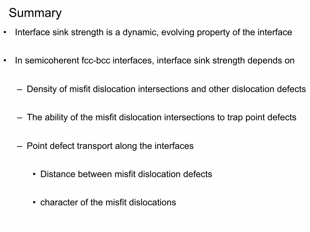
Summary• Interface sink strength is a dynamic, evolving property of the interface
• In semicoherent fcc-bcc interfaces, interface sink strength depends on
– Density of misfit dislocation intersections and other dislocation defects
– The ability of the misfit dislocation intersections to trap point defects
– Point defect transport along the interfaces
• Distance between misfit dislocation defects
• character of the misfit dislocations