tn-317 design value calc options
DESCRIPTION
ADAPT Technical NotesTRANSCRIPT
Technical Note Your Partner in Structural Concrete Design
[email protected] www.adaptsoft.com ADAPT Corporation, Redwood City, California, USA, Tel: (650) 306-2400 Fax (650) 306 2401
ADAPT International Pvt. Ltd, Kolkata, India, Tel: 91 33 302 86580 Fax: 91 33 224 67281
TN317_design_value_calc_options_100608
OPTIONS FOR CALCULATION OF DESIGN VALUES IN CONCRETE FLOORS
Bijan O Aalami
First draft August 6, 2008
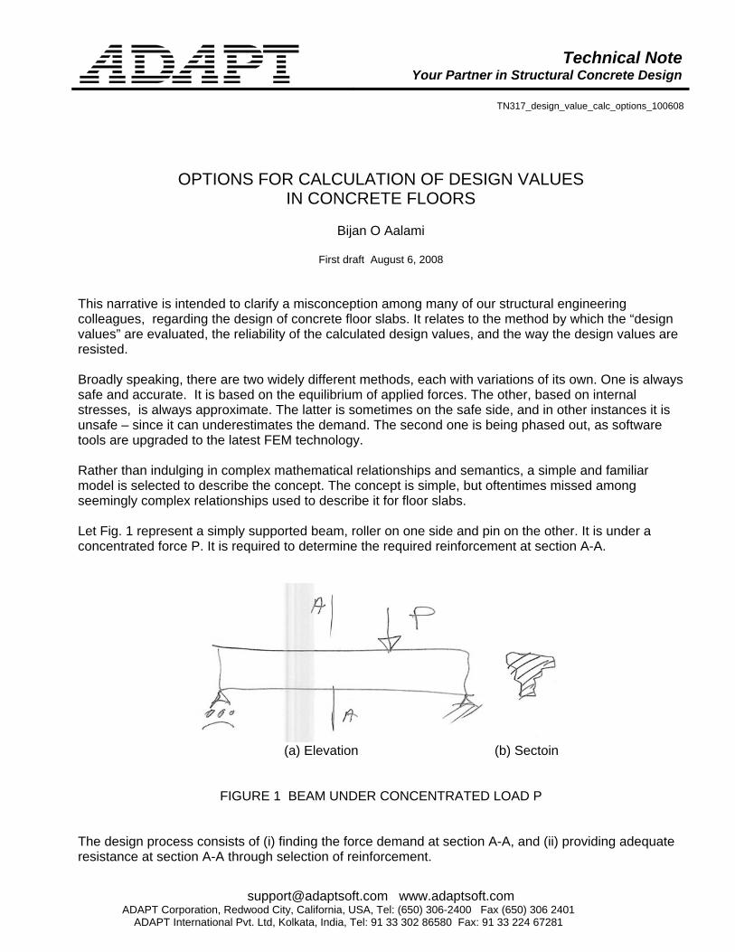
This narrative is intended to clarify a misconception among many of our structural engineering colleagues, regarding the design of concrete floor slabs. It relates to the method by which the “design values” are evaluated, the reliability of the calculated design values, and the way the design values are resisted. Broadly speaking, there are two widely different methods, each with variations of its own. One is always safe and accurate. It is based on the equilibrium of applied forces. The other, based on internal stresses, is always approximate. The latter is sometimes on the safe side, and in other instances it is unsafe – since it can underestimates the demand. The second one is being phased out, as software tools are upgraded to the latest FEM technology. Rather than indulging in complex mathematical relationships and semantics, a simple and familiar model is selected to describe the concept. The concept is simple, but oftentimes missed among seemingly complex relationships used to describe it for floor slabs. Let Fig. 1 represent a simply supported beam, roller on one side and pin on the other. It is under a concentrated force P. It is required to determine the required reinforcement at section A-A.
(a) Elevation (b) Sectoin
FIGURE 1 BEAM UNDER CONCENTRATED LOAD P The design process consists of (i) finding the force demand at section A-A, and (ii) providing adequate resistance at section A-A through selection of reinforcement.
Technical Note
2
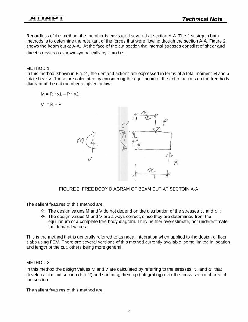
Regardless of the method, the member is envisaged severed at section A-A. The first step in both methods is to determine the resultant of the forces that were flowing though the section A-A. Figure 2 shows the beam cut at A-A. At the face of the cut section the internal stresses consdist of shear and direct stresses as shown symbolically by τ and σ . METHOD 1 In this method, shown in Fig. 2 , the demand actions are expressed in terms of a total moment M and a total shear V. These are calculated by considering the equilibrium of the entire actions on the free body diagram of the cut member as given below.
M = R * x1 – P * x2 V = R – P
FIGURE 2 FREE BODY DIAGRAM OF BEAM CUT AT SECTOIN A-A
The salient features of this method are:
The design values M and V do not depend on the distribution of the stresses τ, and σ ; The design values M and V are always correct, since they are determined from the
equilibrium of a complete free body diagram. They neither overestimate, nor underestimate the demand values.
This is the method that is generally referred to as nodal integration when applied to the design of floor slabs using FEM. There are several versions of this method currently available, some limited in location and length of the cut, others being more general. METHOD 2 In this method the design values M and V are calculated by referring to the stresses τ, and σ that develop at the cut section (Fig. 2) and summing them up (integrating) over the cross-sectional area of the section. The salient features of this method are:

Technical Note
3
The accuracy of the values M and V depend on the (i) accuracy of the stresses τ, and σ , and (ii) the accuracy of the integration;
Since in FEM stresses are ALWAYS approximate, and they are rarely in equilibrium with the applied forces, even if the integration is done correctly, the values obtained for demand forces M and V will be approximate. The design values generally are not on the safe side, if the cut is close to a concentrated load.
This is the method that is generally referred to as “stress integration.” Depending on the method by which the stresses at the cut section are summed, it becomes necessary to either consider, or disallow the contribution of some of the stresses (Mxy in plates and Wood-Armer approximation). DESIGN Refer to Fig. 3. It is important to note that at “design” stage, the stress distribution τ and σ shown in Fig. 2 is DISREGARED. The cracking of the section invalidates the stress distribution shown in Fig. 2, while the equilibrium with the externally applied forces is maintained. Keeping the design values M and V, a different set of force distribution is selected (Fig. 3) to determine the safety of the structure against factored values of M and V. The stress distribution shown in Fig. 2 becomes immaterial.
FIGURE 3 MOMENT RESISTING FORCE DIAGRAM AT ULTIMATE LIMIT STATE ADDITIONAL INFORMATION For more information on this topic refer to the following ADAPT Technical Notes:
ADAPT TN302 “Evaluation of Values at Design Sections Using ADAPT-Builder Platform.” ADAPT-TN315 “A Safety Consideration in Design of Concrete Floor Systems.”
Author’s Note: I have written this note with an in-depth understanding of theory of plates, and full awareness of both the classical and modern methods of plate analysis, and design of concrete floor systems. The following is a selection of work I have done in the field. Books: Aalami, O. B., and Bommer A. “DESGIN FUNDAMENTALS OF POST-TENSIONED CONCRETE FLOORS,” Post-Tensioning Institute, Phoenix, AZ, April 1999 Aalami, B. and Williams, D.G. THIN PLATE DESIGN FOR TRANSVERSE LOADING, John Wiley, USA, 1977, and Crosby Lockwood, UK, 1975.

Technical Note
4
Williams, D.G. and Aalami, B., DESIGN OF THIN PLATES UNDER EDGE COMPRESSION, Crosby Lockwood, UK, 1979. Selection of related articles: Aalami, B. and Chapman, J.C. "Large-Deflection Behavior of Rectangular Orthotropic Plates Under Transverse and Inplane Loads", Proceedings of the Institution of Civil Engineers, March 1969, pp 347-382 and November 1969, pp 263-264. London. Aalami, B. "Large-Deflection of Plates Under Patch Loading", Journal of the Structural Division, American Society of Civil Engineers, November 1972, pp 261-269. Aalami, B. Moukhtarzadeh, A. and Mahmudi-Saati, P. "On Strength Design of Ship Plates Under Inplane and Transverse Loading", Transactions of the Royal Institute of Naval Architects, November 1972, pp 519-534. Aalami, B. "Moment-Rotation Relationship Between Column and Slab", Journal of the American Concrete Institute, May 1972, pp 263-269. Mehrain, M. and Aalami, B. "Rotational Stiffness of Concrete Slabs", Journal of the American Concrete Institute, September 1974, pp 429-435. Aalami, B. O. "Design of Post-Tensioned Floor Slabs," ACI, Concrete International, V.11, No. 6, June 1989, pp. 59-67. Aalami, B. O. (2001)“Software for the Design of Concrete Buildings,” American Concrete Institute, Concrete International Journal, December 29, 2001, pp. 28-35. Aalami, B. O. (2005), “Structural Modeling and Analysis of Concrete Floor Slabs,” ACI, Concrete International, December 2005, pp. 39-43. Aalami, B. O., and Jurgens, J. D. (2003), “Guidelines for the Design of Post-Tensioned Floors,” American Concrete Institute, Concrete International Journal, March 2003, pp. 77-83. (2003)