tnl32 - geo kingsburygeokingsbury.com/wp-content/uploads/2013/12/traub-tnl32-brochure... · stock...
TRANSCRIPT

CNC swiss- and non-swiss
turning center
TNL32

2
Thanks to the outstanding
technical features of the
TRAUB TNL32 CNC swiss-
and non-swiss turning center,
you will notice measurable
improvements in production.
Just take the turrets designed
as NC rotary axes, for exam-
ple. Not only is their indexing
extremely fast, they can also
be freely positioned without
any mechanical locks required.
This allows the use of multiple
tools, which in turn reduces
the chip-to-chip times and
increases the tool pool in the
work area.
The advantage is that you
don’t have to do as much set-
ting up, which results in higher
productivity.
3
New solutions open up
new possibilities

4
TNL32
Ideal for any
production task
The new machine design of the TNL32 was tuned to meet
the varied requirements of typical long-turned and short-
turned parts.
This design gives you a range of benefits:
Simultaneous machining with up to 3 tools (each tool with variable
feed rate)
Clearly structured work area with large axis travels and wide tooling
circles
Excellent accessibility through a large sliding cover
Easy change-over between sliding and fixed headstock operation
Very compact, low footprint machine design
Highest precision due to thermal symmetric machine structure

5
Counter spindle with bottom tool carrier
Powerful counter spindle with large axis travels in the X /Y/Z axes
and integrated tool carrier with 9 stations
Fast acting C-axis positioning
Spindle positioning in 3 axes results in ultimate transfer accuracy
Three-axis rear end machining for parts with complex geometry
The interaction
of systems
Main spindle
Highly dynamic motor spindle
in synchronous design
Fast acting C-axis positioning
for short times per piece
Fluid cooling contributes to
thermal stability
High performance ensures
large chip volume
Smart headstock design with
large Z-axis travel allows the use
as both a sliding and fixed head-
stock lathe
Top tool carrier
10 tool stations
Optional with B-axis
Powerful tool drive on all
stations
Large X/Y/Z-axis travels
Turret indexing designed as an
NC rotary axis (without mechani-
cal lock) allows positioning at any
angle
Chip-to-chip times comparable
to those with a linear tool carrier
Each station can be equipped
with multiple tool holders
Rear end maching unit
8 tool stations
Large travels of counter spin-
dle allow multiple allocations
The special drive design pro-
vides the choice of high speeds
or high torque
Integrated workpiece
discharge by workpiece gripper
Tool carrier adapted to counter spindle allows simultaneous machin-
ing on the main spindle with two independent tools
6
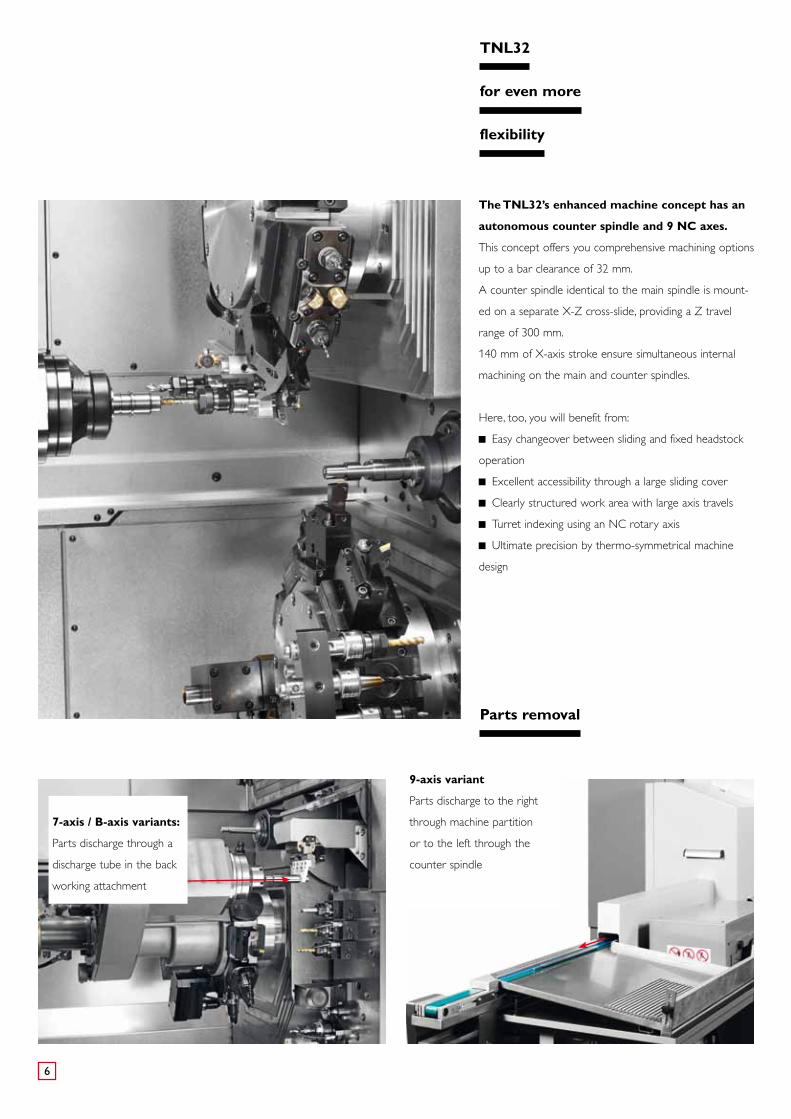
The TNL32’s enhanced machine concept has an
autonomous counter spindle and 9 NC axes.
This concept offers you comprehensive machining options
up to a bar clearance of 32 mm.
A counter spindle identical to the main spindle is mount-
ed on a separate X-Z cross-slide, providing a Z travel
range of 300 mm.
140 mm of X-axis stroke ensure simultaneous internal
machining on the main and counter spindles.
TNL32
for even more
flexibility
Here, too, you will benefit from:
Easy changeover between sliding and fixed headstock
operation
Excellent accessibility through a large sliding cover
Clearly structured work area with large axis travels
Turret indexing using an NC rotary axis
Ultimate precision by thermo-symmetrical machine
design
Parts removal
7-axis / B-axis variants:
Parts discharge through a
discharge tube in the back
working attachment
9-axis variant
Parts discharge to the right
through machine partition
or to the left through the
counter spindle

7
This makes the
tool carriers
so special
Large tool stock
The tooling circle corresponds to remarkable 1444 mm of Y-travel
unwrapped, beating any linear tool carrier.
Turret indexing with NC rotary axis
The newly designed tool carriers are a highlight of the TNL32.
For the first time, the rotary motion is executed by an NC axis with-
out any mechanical locks. This allows you to position both the turret
and the counter spindle very fast at any angle.
Counter spindle with unique kinematics
The innovative TRAUB counter spindle is mounted on an X /Y/Z
cross-slide that simultaneously carries the bottom turret.
1200 1100 1000 900 800 700 600 500 400 300 200 100 0 mm13001400
1910 8 7 6 5 4 3 2

8
Innovative tool mounting system
The new compact shaft system provides significantly
higher rigidity, resulting in longer life cycles and improved
surface quality.
s
Tool 1 engaged
Decelerationtool 1
Turr
et in
dex
ing
Tool 2 engaged
Main time-parallel accelerationtool 2 to 12,000 rpm
10,000
12,000
rpm
5.0 10.4
Tool change from live tool 1 to tool 2
in just 0.4 s chip-to-chip time
5.4
Dual Drive System –
The new drive system from TRAUB, in which the speed for
the follow-up tool is ramped up during main time.
The tool drive
for short
chip-to-chip times
Moderate acceleration as well as gentle braking ensure a long service
life for the tool holders
Time savings during the power-up time of the tools


10
Main spindle drive Motorized spindle / Belt spindle Motorized spindle Belt spindle
Headstock Max. bar capacity 32 32 32 Max. Z stroke swiss - / non swiss turning center 305 / 127 305 / 127 305 / 80 Counter spindle with bottom tool with bottom tool autonomous Max. bar capacity 32 32 32 Max. X/Z-travel 120 / 250 120 / 250 140 / 300
Top turret Stations 10 10 10Axes X / Y / Z X / Y / Z / B X / Y / Z
Bottom turret Stations 9 9 10 Axes X / Y / Z X / Y / Z X / Y / Z Rear end machining unit Stations 8 8 Number of sub-systems 3 3 3
Number of tools Maximum simultaneously engaged 2 2 2
Number of CNC linear axes 9 9 9
Tool pool 20 20 20
Max. number of tools with 3-slot tool holders 60 60 60
Tool shank Ø turret 45 45 45
Tool shank Ø rear end mach. unit 36 36
TNL32-7 TNL32-7B TNL32-9

11
Main spindle drive Motorized spindle / Belt spindle Motorized spindle Belt spindle
Headstock Max. bar capacity 32 32 32 Max. Z stroke swiss - / non swiss turning center 305 / 127 305 / 127 305 / 80 Counter spindle with bottom tool with bottom tool autonomous Max. bar capacity 32 32 32 Max. X/Z-travel 120 / 250 120 / 250 140 / 300
Top turret Stations 10 10 10Axes X / Y / Z X / Y / Z / B X / Y / Z
Bottom turret Stations 9 9 10 Axes X / Y / Z X / Y / Z X / Y / Z Rear end machining unit Stations 8 8 Number of sub-systems 3 3 3
Number of tools Maximum simultaneously engaged 2 2 2
Number of CNC linear axes 9 9 9
Tool pool 20 20 20
Max. number of tools with 3-slot tool holders 60 60 60
Tool shank Ø turret 45 45 45
Tool shank Ø rear end mach. unit 36 36
Three variants,
as diverse as your
requirements
TNL32-7 TNL32-7B TNL32-9

12
Simultaneous machining on
the main spindle
Turning, milling, cross-drilling
Headstock function
Thread chasing without material
return through the autonomous
Z-axis
Sample applications for variants -7, -7B, -9
Highly accurate and complex
rear end machining
Precise pick-up position programmable
Three-axis rear end machining
for parts with complex geometry
Up to 3 tools being used simultaneously
Sample applications for variants -7, -7B
13
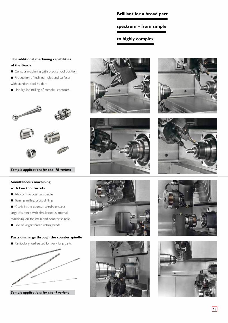
The additional machining capabilities
of the B-axis
Contour machining with precise tool position
Production of inclined holes and surfaces
with standard tool holders
Line-by-line milling of complex contours
Sample applications for the -7B variant
Simultaneous machining
with two tool turrets
Also on the counter spindle
Turning, milling, cross-drilling
X-axis in the counter spindle ensures
large clearance with simultaneous internal
machining on the main and counter spindle
Use of larger thread rolling heads
Parts discharge through the counter spindle
Particularly well-suited for very long parts
Sample applications for the -9 variant
Brilliant for a broad part
spectrum – from simple
to highly complex
14
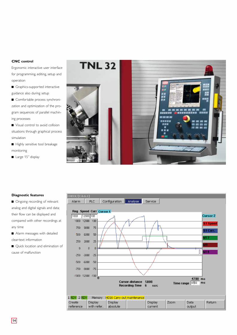
CNC control
Ergonomic interactive user interface
for programming, editing, setup and
operation
Graphics-supported interactive
guidance also during setup
Comfortable process synchroni-
zation and optimization of the pro-
gram sequences of parallel machin-
ing processes
Visual control to avoid collision
situations through graphical process
simulation
Highly sensitive tool breakage
monitoring
Large 15” display
Diagnostic features
Ongoing recording of relevant
analog and digital signals and data;
their flow can be displayed and
compared with other recordings at
any time
Alarm messages with detailed
clear-text information
Quick location and elimination of
cause of malfunction

15
Programming, optimization,
simulation
Realistic real-time simulation for
shorter setup times
3D workpiece display as
standard feature
Graphical display of the working
sequences
Visual collision check before the
machine is run in
External programming
TRAUB WinFlexIPSPlus (option)
Step-by-step parallel program-
ming and simulation possible
Extremely easy synchronization
of machining sequences with
2 sub-systems
Cycle-time optimization already
during programming
Planning and optimization of
the setup operation using “Manual
mode” and “Automatic mode”
functions corresponding to the
real machine
3D simulation and calculation
check provide additional safety
Optionally as PC version and / or
integrated in the control
TRAUB TX8i-s
Get a firm grasp
on your production

16
Work area: TNL32-7 and TNL32-7B
25
40
25
40
140
215
Turning with guide bush
Turning without guide bushTurning without guide bush
Rear endmachining unit
Rear endmachining unit
Tool carrier 1
Counter spindlewith tool carrier 2
305
90° ±5°
127
720
320
215
140
max. 265
25
40
25
40
305
127
305
320
140
14014
014
0
Rear end machining unit
Tool carrier 1
Counter spindlewith tool carrier 2
Turning without guide bush
Turning with guide bush

17
Technical data
TNL32-7 Motorized spindle TNL32-7 Belt spindle TNL32-7B Headstock Max. bar capacity mm 32 32 Max. Z-travel Swiss- and non swiss turning center mm 305 / 127* 305 / 127 Max. speed rpm 8000 6400 8000 Power at 100% /40% kW 6.7 / 10.7 3,7 / 5,5 6,7 / 10,7 Torque at 100% /40% Nm 21 / 32 20,4 / 43,7 21 / 32 C-axis resolution Degrees 0,001 0,001 Max. rapid traverse rate Z m/min 20 20 *Non swiss turning center
Top tool turret Tool mountings Number 10 10 Driven tools Number 10 10 Max. speed rpm 12000 12000 Mounting-ø mm 45 45 Power at 100% /40% kW 1,5 / 3,4 1,5 / 3,4 Turning tool cross-section mm 16 x 16 16 x 16 Slide travel X mm 140 215 Slide travel Y mm -40 / +25 -40 / +25 Slide travel Z mm 305 720 Rapid traverse rate X / Y / Z m/min 20 / 20 / 20 20 / 20 / 40 Chip-to-chip time s <0,3 <0,3 Swievel angle B Degrees - 100
Bottom tool turret Tool mountings Number 9 9 Driven tools Number 9 9 Max. speed rpm 12000 12000 Power at 100% /40% kW 1,5 / 3,4 1,5 / 3,4 Mounting-ø mm 45 45 Turning tool cross-section mm 16 x 16 16 x 16 Slide travel X mm 140 140 Slide travel Y mm -25 / +40 -25 / +40 Slide travel Z mm 320 320 Rapid traverse rate X / Y / Z m/min 20 / 20 / 20 20 / 20 / 20 Chip-to-chip time s <0,3 <0,3
Counter spindle Max. clamping depth / diameter mm 250 / 32 250 / 32 Max. speed rpm 8000 6000 8000 Power at 100% /40% kW 2 / 4,5 2 / 4,5 Torque at 100% /40% Nm 6,9 / 15,3 6,9 / 15,3 C-axis resolution Degrees 0,001 0,001
Rear end machining unit Tool mountings Number 8 8 Driven tools Number 4 4 Mounting-ø mm 36 36 Max. speed rpm 12000 12000 Power at 100% /25% kW 1,5 / 3,4 1,5 / 3,4
Cooling lubricant unitBasic unit Pump pressure bar 3 / 8 3 / 8 Tank capacity l 500 500 Pump capacity 3 / 8 bar l/min 80 / 100 80 / 100 Filter fineness µm 250 250
Medium pressure (option) Pump pressure bar 20 20 Pump capacity l/min 80 80 Filter fineness µm 250 250
Hydraulic unit Tank capacity l 11 11
Machine dimensions Length x width x height mm 3870 x 1670 x 2500 3870 x 1670 x 2500 Weight up to approx. kg 6850** 7000** Connecting power kW 28 28 ** depending on equipment
18
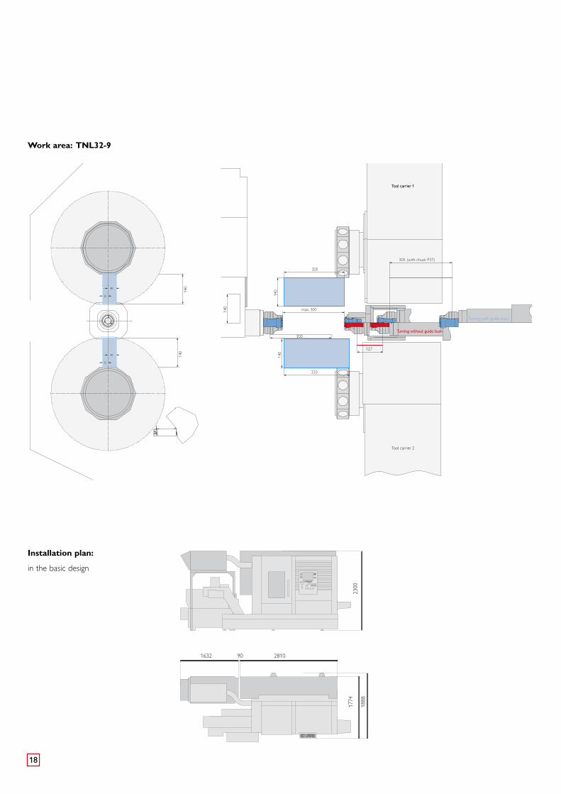
Work area: TNL32-9
305
305 (with chuck F37)
300
320
127
max. 300140
140
140
25
40
25
40
140
140
25
40
25
40
Turning with guide bush
Turning without guide bushTurning without guide bush
Tool carrier 2
Tool carrier 1Tool carrier 1
Installation plan:
in the basic design
1632
1774
2810
1888
2300
90

19
TNL32-9 Headstock Max. bar capacity mm 32 Max. Z-travel Swiss- and non swiss turning center mm 1) 305 / 127 Max. speed rpm 6400 Power at 100% /40% kW 3,7 / 5,5 Torque at 100% /40% Nm 29,4 / 43,7 C-axis resolution Degrees 0,001 Max. rapid traverse rate Z m/min 20
Top tool turret Tool mountings Number 10 Driven tools Number 10 Max. speed rpm 12000 Mounting-ø mm 45 Power at 100% /40% kW 1,5 / 3,4 Turning tool cross-section mm 16 x 16 Slide travel X mm 140 Slide travel Y mm -40 / +25 Slide travel Z mm 300 Rapid traverse rate X / Y / Z m/min 20 / 20 / 20 Chip-to-chip time s <0,3
Bottom tool turret Tool mountings Number 10 Driven tools Number 10 Max. speed rpm 12000 Power at 100%/40% kW 1,5 / 3,4 Mounting-ø mm 45 Turning tool cross-section mm 16 x 16 Slide travel X mm 140 Slide travel Y mm -25 / +40 Slide travel Z mm 320 Rapid traverse rate X / Y / Z m/min 20 / 20 / 20 Chip-to-chip time s <0,3
Counter spindle Max. bar capacity mm 32 (30*) Max. speed rpm 10000 Power at 100% /40% kW 2,2 / 3,7 Torque at 100% /40% Nm 14 / 23,5 Slide travel X mm 100 Slide travel Z mm 262 C-axis resolution Degrees 0,001 Rapid traverse rate X / Z m/min 20 / 40
Cooling lubricant unitBasic unit Pump pressure bar 3 / 8 Tank capacity l 500 Pump capacity 3 / 8 bar l/min 40 / 60 Filter fineness µm 250
Hydraulic unit Tank capacity l 11
Machine dimensions Length x width x height mm 3870 x 1670 x 2500 Weight up to approx. kg 7000** Connecting power kW 28 * Discharging through the counter spindle** depending on equipment1) The headstock stroke depends on the clamping device being used
Technical data

09.1
3 –
846/
1 M
E S
ubje
ct t
o ch
ange
with
out
prio
r no
tice
TRAUB Drehmaschinen
GmbH & Co. KG
Hauffstraße 4
73262 Reichenbach, Germany
Tel. +49 (7153) 502-0
Fax +49 (7153) 502-694
www.traub.de