tnms m surpass hit 7060 lct userguide
TRANSCRIPT

s
Instructions
TNMS-M SURPASS hiT 7060 3.1 LCT
User Manual
A42022-L5969-A 53-1-7619

User Manual Instructions TNMS-M SURPASS hiT 7060 3.1 LCT
Copyright (C) Siemens AG 2004
Issued by the Siemens Communications Hofmannstraße 51 D-81359 München
Technical modifications possible. Technical specifications and features are binding only insofar as they are specifically and expressly agreed upon in a written contract.
2 A42022-L5969-A 53-1-7619
Important Notice on Product Safety Elevated voltages are inevitably present at specific points in this electrical equipment. Some of the parts may also have elevated operating temperatures. Systems with forced ventilation have rotating items. Non-observance of these conditions and the safety instructions can result in personal injury or in property damage. The system complies with the standard EN 60950 / IEC 60950. All equipment connected has to comply with the applicable safety standards. Mount the systems in areas with restricted access only. Only trained and qualified personnel may install, operate, and maintain the systems. The same text in German: Wichtiger Hinweis zur Produktsicherheit In elektrischen Anlagen stehen zwangsläufig bestimmte Teile der Geräte unter Spannung. Einige Teile können auch eine hohe Betriebstemperatur aufweisen. Anlagen mit Zwangsbelüftung haben drehende Teile. Eine Nichtbeachtung dieser Situation und der Warnungshinweise kann zu Körperverletzungen und Sachschäden führen. Das System entspricht den Anforderungen der EN 60950 / IEC 60950. Angeschlossene Geräte müssen die zutreffenden Sicherheitsbestimmungen erfüllen. Die Anlagen dürfen nur in Betriebsstätten mit beschränktem Zutritt aufgebaut werden. Die Anlagen dürfen nur durch geschultes und qualifiziertes Personal installiert, betrieben und gewartet werden. Trademarks: All designations used in this document can be trademarks, the use of which by third parties for their own purposes could violate the rights of their owners.
!

Instructions User ManualTNMS-M SURPASS hiT 7060 3.1 LCT
A42022-L5969-A 53-1-7619 3
Contents
1 Notes on this Documentation ........................................................................13 1.1 Customer Documentation .............................................................................13 1.2 Complementary Documents..........................................................................13 1.3 Symbols Used in the Customer Documentation ...........................................14 1.3.1 Symbol for Warnings.....................................................................................14 1.3.2 Symbols for Notes.........................................................................................14 1.3.3 Symbols for Menu Displays and Text Inputs.................................................14 1.4 Notes on Licensed Software .........................................................................14
2 Introduction....................................................................................................15
3 Features ........................................................................................................16
4 Hardware Configuration ................................................................................18
5 Software Configuration..................................................................................19
6 Installation .....................................................................................................20 6.1 Route Configuration ......................................................................................20 6.2 Installing the LCT software package.............................................................25 6.3 Uninstalling the LCT Software Package .......................................................31
7 Starting and Shutting down TNMS-M SURPASS hiT 7060 LCT ..................33 7.1 Starting TNMS-M SURPASS hiT 7060 LCT .................................................33 7.2 Shutting Down TNMS-M SURPASS hiT 7060 LCT ......................................33
8 Main Interface Features ................................................................................34 8.1 Main Window.................................................................................................34 8.1.1 Title Bar .........................................................................................................34 8.1.2 Main Menu Bar..............................................................................................34 8.1.3 Work Area .....................................................................................................37 8.2 Submenus (with Right Mouse Button Click)..................................................37 8.2.1 SDH Card ......................................................................................................37 8.2.2 CC Card ........................................................................................................37 8.2.3 Ethernet Card................................................................................................37
9 NE Configuration and Management..............................................................38 9.1 Chassis View.................................................................................................38 9.2 Synchronizing NE..........................................................................................39 9.3 NE Property Configuration ............................................................................40 9.4 Shutting down NE .........................................................................................41 9.5 FTP Settings..................................................................................................42 9.6 NE Software Management ............................................................................43 9.7 MIB Management..........................................................................................44 9.8 NE Timing Setting .........................................................................................46 9.9 NE Trap Destination Configuration ...............................................................47 9.9.1 Changing NE IP ............................................................................................48 9.9.2 ChangIng Ethernet IP....................................................................................48

User Manual Instructions TNMS-M SURPASS hiT 7060 3.1 LCT LCT
4 A42022-L5969-A 53-1-7619
10 SDH Configuration and Management ...........................................................50 10.1 Card Configuration and Management ...........................................................50 10.1.1 SDH Card Configuration and Management ..................................................50 10.1.2 Synchronizing the Card.................................................................................51 10.1.3 Deleting Card ................................................................................................52 10.2 SDH Port Configuration and Management....................................................52 10.2.1 Port Configuration .........................................................................................52 10.2.2 Port Status.....................................................................................................53 10.3 E1 Ports Property Configuration ...................................................................53 10.4 OSI Configuration..........................................................................................55 10.5 CC Configuration and Management..............................................................56 10.5.1 Querying Current Cross-Connection.............................................................56 10.5.2 Adding a New Cross-Connection ..................................................................57 10.5.3 Deleting a Connection...................................................................................58 10.6 TP Configuration and Management ..............................................................58 10.6.1 Querying Current Terminal Point ..................................................................58 10.6.2 TP Multiplexing Structure ..............................................................................60 10.7 Synchronization Management.......................................................................62 10.7.1 Global Settings ..............................................................................................63 10.7.2 Configuring the Timing Source of NE............................................................64 10.7.3 Configuring the System Clock.......................................................................66 10.7.4 Configuring the Reference ............................................................................66 10.8 EOW Configuration .......................................................................................68
11 Ethernet Configuration and Management .....................................................69 11.1 Bridge Configuration......................................................................................69 11.2 LAN Card Configuration and Management ...................................................69 11.2.1 LAN Port Properties ......................................................................................70 11.2.2 VLAN Rate Limiting .......................................................................................71 11.2.3 CoS Configuration .........................................................................................73 11.3 WAN Port Configuration................................................................................75 11.4 VLAN Management .......................................................................................76 11.5 Static MAC Address Configuration................................................................79 11.6 ACL Configuration .........................................................................................81 11.7 Group Broadcast Configuration.....................................................................82 11.8 RSTP Configuration ......................................................................................83
12 Protection Management ................................................................................85 12.1 CC 1+1 Protection.........................................................................................85 12.2 SNCP Management ......................................................................................85 12.2.1 Viewing and Modifying SNCP .......................................................................86 12.2.2 Creating SNCP..............................................................................................88 12.2.3 Deleting SNCP ..............................................................................................89 12.2.4 Switching SNCP............................................................................................90 12.3 MSP Management.........................................................................................90 12.4 MSSPRING Management .............................................................................93 12.4.1 Creating MSSPRing ......................................................................................94 12.4.2 Modifying MSSPring......................................................................................97

Instructions User ManualTNMS-M SURPASS hiT 7060 3.1 LCT
A42022-L5969-A 53-1-7619 5
12.4.3 Deleting MSSPRing ....................................................................................100
13 OSPFOSPF.................................................................................................101 13.1 OSPF General.............................................................................................101 13.2 OSPF Areas ................................................................................................103 13.3 OSPF Interfaces..........................................................................................105 13.4 OSPF Interface Metrics...............................................................................107 13.5 OSPF Neighbors .........................................................................................108 13.6 OSPF LSDB ................................................................................................109 13.7 OSPF Ext LSDB..........................................................................................110
14 Maintenance................................................................................................111 14.1 Loop-back Test Management .....................................................................111 14.1.1 Querying Loopback Status..........................................................................111 14.1.2 Setting Loopback Test ................................................................................111 14.2 LED Test .....................................................................................................112
15 Performance Monitoring Management........................................................113 15.1 Overview of Performance Monitoring..........................................................113 15.1.1 SDH Performance Monitoring .....................................................................113 15.1.2 Data Performance Monitoring Parameters .................................................116 15.2 SDH Performance Monitoring .....................................................................117 15.2.1 Filter Setting ................................................................................................118 15.2.2 Editing Monitored Parameter ......................................................................119 15.2.3 Alarm Threshold..........................................................................................120 15.2.4 History SDH Performance...........................................................................121 15.3 Ethernet Performance Monitoring Configuration.........................................122 15.3.1 Filter Setting ................................................................................................123 15.3.2 Editing Monitored Parameter ......................................................................124 15.3.3 Ethernet PM Thresholds .............................................................................125 15.3.4 History Ethernet Performance.....................................................................127
16 Alarm and Event Management....................................................................129 16.1 Overview of Alarms .....................................................................................129 16.2 NE Alarms ...................................................................................................129 16.2.1 Current Alarms ............................................................................................129 16.2.2 Viewing Active Alarms.................................................................................130 16.2.3 Reviewing the Current Alarms ....................................................................131 16.2.4 Viewing Alarm Detail ...................................................................................131 16.2.5 Clearing Alarms...........................................................................................132 16.3 LED Indicators.............................................................................................132 16.4 Exporting Alarms.........................................................................................133 16.4.1 Exporting Active Alarms to a File ................................................................133 16.4.2 Printing Active Alarms .................................................................................135 16.5 Configure Fault Management......................................................................136 16.5.1 Audio Alarm Configuration ..........................................................................136 16.5.2 Alarm Type List Management .....................................................................137 16.6 Alarm Configuration for Single NE ..............................................................138 16.6.1 Alarm Inhibit Configuration..........................................................................138

User Manual Instructions TNMS-M SURPASS hiT 7060 3.1 LCT LCT
6 A42022-L5969-A 53-1-7619
16.6.2 Alarm Out Configuration..............................................................................139 16.6.3 MDI/MDO Configuration..............................................................................139 16.7 Displaying the Node Event Log...................................................................141 16.7.1 Interpreting the Node Event Log .................................................................142 16.7.2 Events Management ...................................................................................142 16.7.3 Hardware Events.........................................................................................142 16.7.4 Software Events ..........................................................................................143
17 Resource and Database Management .......................................................144 17.1 NE Usage Statistics.....................................................................................144
18 How To ........................................................................................................145 18.1 Creating a TU12 Cross-Connection between STM-4 and STM-4/1 ...........145 18.2 Creating a Bi-Direction Cross-Connection of TU12 from STM-4 OC to STM-
4/1 OC .........................................................................................................150 18.3 Creating Timing Synchronized Network......................................................155 18.4 Configure Layer 2 100Mbps Ethernet Service ............................................161 18.5 Configure 1G Transparent Transmission Ethernet Service ........................169 18.6 Monitoring One STM-16 Port Current Performance ...................................172 18.7 Creating Multiplex-Section Protection between Two NEs...........................175 18.8 Creating SNCP Between Two NEs Using Two Ports of MainBoard(STM-4)177
19 Abbreviation ................................................................................................181
20 Index............................................................................................................183

Instructions User ManualTNMS-M SURPASS hiT 7060 3.1 LCT
A42022-L5969-A 53-1-7619 7
Illustrations Fig. 2.1 TNMS-M Series Products................................................................................15 Fig. 6.1 Open Hyper Terminal ......................................................................................20 Fig. 6.2 Hyper Terminal--Connection Description ........................................................21 Fig. 6.3 Hyper Terminal--Connect To...........................................................................21 Fig. 6.4 Hyper Terminal--COM1 Properties ..................................................................22 Fig. 6.5 CLI Window--Login ..........................................................................................22 Fig. 6.6 Main Menu.......................................................................................................23 Fig. 6.7 User Table .......................................................................................................23 Fig. 6.8 Edit a Given User ............................................................................................24 Fig. 6.9 IP Address Configuration.................................................................................24 Fig. 6.10 Add Static Route Information ........................................................................25 Fig. 6.11 Setup Wizard Welcome Screen ....................................................................26 Fig. 6.12 Select Destination Location...........................................................................26 Fig. 6.13 Select Start Menu Folder...............................................................................27 Fig. 6.14 Select Additional Tasks .................................................................................27 Fig. 6.15 Ready to Install..............................................................................................28 Fig. 6.16 Installing ........................................................................................................28 Fig. 6.17 Exit Setup ......................................................................................................29 Fig. 6.18 Completing the Setup....................................................................................29 Fig. 6.19 TNMS-M SURPASS hiT 7060 LCT Desktop Icon.........................................29 Fig. 6.20 Start Menu .....................................................................................................30 Fig. 6.21 Input NE’s Login Information .........................................................................30 Fig. 6.22 LCT GUI ........................................................................................................31 Fig. 6.23 Uninstall TNMS-M SURPASS hiT 7060 LCT ................................................31 Fig. 6.24 Confirm Window for Uninstall ........................................................................31 Fig. 6.25 Uninstall Status..............................................................................................32 Fig. 6.26 Complete Uninstalling Process .....................................................................32 Fig. 7.1 TNMS-M SURPASS hiT 7060 LCT Main Window ..........................................33 Fig. 8.1 Main Window ...................................................................................................34 Fig. 9.1 Chassis View ...................................................................................................38 Fig. 9.2 Refresh Chassis ..............................................................................................39 Fig. 9.3 Synchronize NE...............................................................................................39 Fig. 9.4 NE Properties ..................................................................................................40 Fig. 9.5 Shutdown NE...................................................................................................41 Fig. 9.6 Shutdown Information......................................................................................42 Fig. 9.7 FTP Settings....................................................................................................42 Fig. 9.8 NE Software Management ..............................................................................43 Fig. 9.9 FTP Setting......................................................................................................44 Fig. 9.10 MIB Management ..........................................................................................45 Fig. 9.11 FTP Setting....................................................................................................45 Fig. 9.12 NE Time Settings...........................................................................................46 Fig. 9.13 NE Destination...............................................................................................47 Fig. 9.14 Confirmation for Delete..................................................................................47 Fig. 9.15 NE Communication Parameters Configure ...................................................48 Fig. 9.16 Change NE IP................................................................................................48 Fig. 9.17 Configure Ethernet IP ....................................................................................48 Fig. 10.1 Card Properties .............................................................................................50 Fig. 10.2 Synchronize Card ..........................................................................................51 Fig. 10.3 Port Properties...............................................................................................52

User Manual Instructions TNMS-M SURPASS hiT 7060 3.1 LCT LCT
8 A42022-L5969-A 53-1-7619
Fig. 10.4 Card Properties............................................................................................. 54 Fig. 10.5 E1 Port Properties ........................................................................................ 54 Fig. 10.6 OSI Configuration ......................................................................................... 55 Fig. 10.7 Cross-Connect Management........................................................................ 56 Fig. 10.8 Create Cross-Connect.................................................................................. 57 Fig. 10.9 Confirmation for deleting Cross-Connections............................................... 58 Fig. 10.10 TP Configuration (View 1 - As Presented) ................................................. 59 Fig. 10.11 TP Configuration (View 2 - Engaged)......................................................... 59 Fig. 10.12 TP Multiplexing Structure Query................................................................. 60 Fig. 10.13 TP Multiplexing Structure, View 1............................................................... 61 Fig. 10.14 TP Multiplexing Structure, View 2............................................................... 61 Fig. 10.15 Add Mapping............................................................................................... 62 Fig. 10.16 Synchronization Management .................................................................... 63 Fig. 10.17 Global Settings ........................................................................................... 63 Fig. 10.18 Station Clock Settings Reference Time IN ................................................. 64 Fig. 10.19 Station Clock Settings Reference Time Out............................................... 65 Fig. 10.20 Station Clock Settings Reference Time Out (Clock Out Reference).......... 65 Fig. 10.21 System Clock.............................................................................................. 66 Fig. 10.22 Timing Source Reference Properties ......................................................... 67 Fig. 10.23 EOW Config................................................................................................ 68 Fig. 11.1 Bridge Properties.......................................................................................... 69 Fig. 11.2 LAN Port Configuration................................................................................. 70 Fig. 11.3 Rate Limit Config .......................................................................................... 71 Fig. 11.4 VLAN Rate Limit Config................................................................................ 72 Fig. 11.5 Add VLAN Rate Limit.................................................................................... 72 Fig. 11.6 Change Cos.................................................................................................. 73 Fig. 11.7 VLAN+Port Cos Config................................................................................. 74 Fig. 11.8 Add VLAN Cos.............................................................................................. 74 Fig. 11.9 WAN Port Config .......................................................................................... 75 Fig. 11.10 Bandwidth Configuration ............................................................................ 76 Fig. 11.11 VLAN Management .................................................................................... 77 Fig. 11.12 Modify VLAN Based on VLAN .................................................................... 78 Fig. 11.13 Modify VLAN Based on Ports ..................................................................... 79 Fig. 11.14 Static MAC Address Configuration ............................................................. 80 Fig. 11.15 Add MAC Address ...................................................................................... 80 Fig. 11.16 ACL Config ................................................................................................. 81 Fig. 11.17 Add ACL...................................................................................................... 81 Fig. 11.18 Group Broadcast Configuration.................................................................. 82 Fig. 11.19 Add MAC Address ...................................................................................... 83 Fig. 11.20 RSTP Properties Configuration .................................................................. 84 Fig. 11.21 Port RSTP Configuration ............................................................................ 84 Fig. 12.1 CC 1+1 Protection ........................................................................................ 85 Fig. 12.2 SNCP Management...................................................................................... 86 Fig. 12.3 View/Modify SNCP ....................................................................................... 87 Fig. 12.4 Create Cross-Connect.................................................................................. 88 Fig. 12.5 Create SNCP................................................................................................ 89 Fig. 12.6 Delete SNCP ................................................................................................ 89 Fig. 12.7 SNCP Switch ................................................................................................ 90 Fig. 12.8 MSP Management........................................................................................ 90 Fig. 12.9 Searching Result of Multiplex Section Protection......................................... 91 Fig. 12.10 External Commands ................................................................................... 92

Instructions User ManualTNMS-M SURPASS hiT 7060 3.1 LCT
A42022-L5969-A 53-1-7619 9
Fig. 12.11 Create Linear Multiplex Section Protection Group ......................................92 Fig. 12.12 MSSPRing Management.............................................................................93 Fig. 12.13 Set Ring Property ........................................................................................94 Fig. 12.14 Warning Window .........................................................................................94 Fig. 12.15 Set NEs in Ring ...........................................................................................95 Fig. 12.16 Set East and West Sides.............................................................................95 Fig. 12.17 Set Peer East and West Sides ....................................................................96 Fig. 12.18 Set NUT.......................................................................................................96 Fig. 12.19 Set WTR ......................................................................................................97 Fig. 12.20 MSSPRING List...........................................................................................97 Fig. 12.21 MSSPRing Details .......................................................................................98 Fig. 12.22 Command of MS SPRing ............................................................................98 Fig. 12.23 Advanced Configuration ..............................................................................99 Fig. 12.24 Delete MSSPRing......................................................................................100 Fig. 13.1 OSPF Submenu ..........................................................................................101 Fig. 13.2 OSPF General .............................................................................................102 Fig. 13.3 OSPF Area ..................................................................................................103 Fig. 13.4 Add OSPF Area...........................................................................................104 Fig. 13.5 Edit OSPF Area ...........................................................................................105 Fig. 13.6 OPSF Interface............................................................................................105 Fig. 13.7 OSPF Interface Metric .................................................................................107 Fig. 13.8 OSPF Neighbor ...........................................................................................108 Fig. 13.9 OSPF Link State Database .........................................................................109 Fig. 13.10 OSPF External Link State Database.........................................................110 Fig. 14.1 Loopback Test .............................................................................................111 Fig. 14.2 Lookback Test Configure.............................................................................112 Fig. 14.3 LED Test......................................................................................................112 Fig. 15.1 SDH Current Performance ..........................................................................117 Fig. 15.2 Monitor Point Filter ......................................................................................118 Fig. 15.3 Select Terminal Point ..................................................................................119 Fig. 15.4 Edit Properties of Monitored Parameter ......................................................119 Fig. 15.5 Alarm Threshold ..........................................................................................120 Fig. 15.6 SDH History Performance ...........................................................................122 Fig. 15.7 Ethernet Current Performance ....................................................................123 Fig. 15.8 Monitor Point Filter ......................................................................................123 Fig. 15.9 Select Port ...................................................................................................124 Fig. 15.10 Edit Properties of Performance Monitor ....................................................124 Fig. 15.11 1 Second Ethernet Thresholds..................................................................125 Fig. 15.12 Monitor Point Filter ....................................................................................125 Fig. 15.13 Select Ports ...............................................................................................126 Fig. 15.14 Selected Ports ...........................................................................................126 Fig. 15.15 Edit Port Threshold....................................................................................127 Fig. 15.16 Ethernet History Performance ...................................................................127 Fig. 16.1 Chassis View with Open Current Alarms ....................................................130 Fig. 16.2 Fault, Active Alarms.....................................................................................130 Fig. 16.3 Alarm Count by Severity..............................................................................131 Fig. 16.4 Active Alarms...............................................................................................131 Fig. 16.5 Alarm Detail .................................................................................................132 Fig. 16.6 Clear Alarm..................................................................................................132 Fig. 16.7 Report Alarms..............................................................................................133 Fig. 16.8 Report Alarms Preview................................................................................134

User Manual Instructions TNMS-M SURPASS hiT 7060 3.1 LCT LCT
10 A42022-L5969-A 53-1-7619
Fig. 16.9 Save File..................................................................................................... 134 Fig. 16.10 Print Alarms .............................................................................................. 135 Fig. 16.11 Print Alarms Preview ................................................................................ 135 Fig. 16.12 Print Setup ................................................................................................ 136 Fig. 16.13 Audio Alarm Configuration........................................................................ 136 Fig. 16.14 Alarm Type List Management................................................................... 137 Fig. 16.15 Modify User Defined Severity of Alarm .................................................... 138 Fig. 16.16 Alarm Inhibit Configuration ....................................................................... 138 Fig. 16.17 Alarm Out Configuration ........................................................................... 139 Fig. 16.18 MDI Configuration..................................................................................... 140 Fig. 16.19 MDO Configuration................................................................................... 141 Fig. 16.20 Node Event Log........................................................................................ 142 Fig. 17.1 Usage Statistics .......................................................................................... 144 Fig. 18.1 TP Multiplexing Structure ........................................................................... 145 Fig. 18.2 Query Result............................................................................................... 145 Fig. 18.3 Expanding Tree Graph ............................................................................... 146 Fig. 18.4 Mapping AU4 to TU12 ................................................................................ 146 Fig. 18.5 Result of Mapping....................................................................................... 147 Fig. 18.6 Mapping TU12 to AU4 ................................................................................ 147 Fig. 18.7 Cross-Connect Management Menu............................................................ 148 Fig. 18.8 Cross-Connect Management...................................................................... 148 Fig. 18.9 Create Cross-Connect................................................................................ 149 Fig. 18.10 TP Multiplexing Structure ......................................................................... 150 Fig. 18.11 Query Result............................................................................................. 151 Fig. 18.12 Expanding Tree Graph ............................................................................. 151 Fig. 18.13 Mapping AU4 to TU12 .............................................................................. 152 Fig. 18.14 Result of Mapping..................................................................................... 152 Fig. 18.15 Mapping TU12 to AU4 .............................................................................. 153 Fig. 18.16 Cross-Connection Menu........................................................................... 153 Fig. 18.17 Cross-Connect Management.................................................................... 154 Fig. 18.18 Create Cross-Connect.............................................................................. 154 Fig. 18.19 Create Cross-Connect.............................................................................. 155 Fig. 18.20 Three (3) Node Ring................................................................................. 156 Fig. 18.21 Synchronization Management .................................................................. 156 Fig. 18.22 Station Clock Setting ................................................................................ 157 Fig. 18.23 Timing Source Reference Properties ....................................................... 157 Fig. 18.24 Remove Timing Source Reference .......................................................... 158 Fig. 18.25 System Clock............................................................................................ 158 Fig. 18.26 Timing Results .......................................................................................... 159 Fig. 18.27 Synchronization Management .................................................................. 160 Fig. 18.28 Timing Source Reference Management................................................... 160 Fig. 18.29 Synchronization Management .................................................................. 161 Fig. 18.30 Bridge Configuration Tab.......................................................................... 162 Fig. 18.31 Bridges Properties .................................................................................... 162 Fig. 18.32 WAN Port Config ...................................................................................... 163 Fig. 18.33 Bandwidth Configuration .......................................................................... 164 Fig. 18.34 VLAN Management .................................................................................. 165 Fig. 18.35 VLAN Config ............................................................................................. 166 Fig. 18.36 VLAN Management: Query Result ........................................................... 167 Fig. 18.37 Create CrossConnect ............................................................................... 168 Fig. 18.38 CrossConnect Management..................................................................... 169

Instructions User ManualTNMS-M SURPASS hiT 7060 3.1 LCT
A42022-L5969-A 53-1-7619 11
Fig. 18.39 SURPASS hiT7060 Chassis View.............................................................169 Fig. 18.40 WAN Port Config .......................................................................................170 Fig. 18.41 Bandwidth Configuration ...........................................................................170 Fig. 18.42 Create Cross-Connect...............................................................................171 Fig. 18.43 Cross-Connect Management ....................................................................172 Fig. 18.44 Current SDH Performance Tab .................................................................172 Fig. 18.45 SDH Current Performance ........................................................................173 Fig. 18.46 Monitor Point Filter ....................................................................................173 Fig. 18.47 Select Terminal Point ................................................................................174 Fig. 18.48 Monitor Point Filter ....................................................................................174 Fig. 18.49 SDH Current Performance ........................................................................175 Fig. 18.50 Linear Multiplex Section Protection Group Management..........................176 Fig. 18.51 Create Linear Multiplex Section Protection Group ....................................176 Fig. 18.52 Linear Multiplex Section Protection Group Management..........................177 Fig. 18.53 SNCP Example..........................................................................................177 Fig. 18.54 SNCP Management...................................................................................178 Fig. 18.55 Create and Config SNCP ..........................................................................179 Fig. 18.56 SNCP Protection of NE A..........................................................................179 Fig. 18.57 SNCP Switch .............................................................................................180

User Manual Instructions TNMS-M SURPASS hiT 7060 3.1 LCT LCT
12 A42022-L5969-A 53-1-7619
Tables Tab. 3.1 Feature List .................................................................................................... 17 Tab. 4.1 Minimum Hardware Requirement of TNMS-M SURPASS hiT 7060 LCT..... 18 Tab. 8.1 Main Menu Bar .............................................................................................. 36 Tab. 9.1 NE Properties ................................................................................................ 41 Tab. 9.2 NE Software Management Window Field Description .................................. 43 Tab. 10.1 Card Identification ....................................................................................... 51 Tab. 10.2 Port Configuration ....................................................................................... 53 Tab. 10.3 Port Status................................................................................................... 53 Tab. 10.4 TP Management Parameters ...................................................................... 60 Tab. 10.5 Timing Source Management Time IN Window Parameters........................ 64 Tab. 12.1 SNCP Properties ......................................................................................... 87 Tab. 15.1 Regenerator Section SES threshold xx% (for BIP-8)................................ 114 Tab. 15.2 Defects Resulting in a Near-end Severely Errored Second...................... 114 Tab. 15.3 Defects resulting in a Far-end Severely Errored Second.......................... 114 Tab. 15.4 Multiplex Section SES threshold xx% (For BIP-1) .................................... 115 Tab. 15.5 Defects Resulting in a Near-end Severely Errored Second...................... 115 Tab. 15.6 Defects Resulting in a Far-end Severely Errored Second ........................ 116 Tab. 15.7 Path Overhead Section SES Threshold xx% (For BIP-2, BIP-8) .............. 116 Tab. 15.8 PM Management Functions ...................................................................... 117 Tab. 15.9 Default Value and Value Range for a Fixed 15-minute Period ................. 121 Tab. 15.10 Default value and Value Range for a Fixed 24-hour Period ................... 121 Tab. 15.11 Primary Ethernet PM Function ................................................................ 122 Tab. 16.1 Active Alarms Information ........................................................................ 131 Tab. 16.2 LED Status ................................................................................................ 133 Tab. 16.3 Management Events ................................................................................. 142 Tab. 16.4 Hardware Events....................................................................................... 143 Tab. 16.5 Software Events ........................................................................................ 143

Instructions User ManualTNMS-M SURPASS hiT 7060 3.1 LCT
A42022-L5969-A 53-1-7619 13
1 Notes on this Documentation
1.1 Customer Documentation The Customer Documentation of the SURPASS hiT 7060 comprises the following descriptions and manuals:
• Technical Manual
The Technical Manual gives an overview of the application, performance features, interfaces, and functions of the TNMS-M SURPASS hiT 7060. It also contains the most important technical data.
The Technical Description does not contain any instructions to operate the product.
• Installation and Testing Guide
The Installation and Test Manual ITMN contains instructions on mounting, connecting, and commissioning the TNMS-M SURPASS hiT 7060, and connecting and commissioning the LCT operating terminals.
• Trouble Manual The Trouble Manual provides information about the alarm list TNMS-M SURPASS hiT 7060 supports and troubleshooting procedures.
• TNMS-M SURPASS hiT 7060 LCT User Manual The LCT User Manual provides information about the LCT (features, configuration, installation, etc.) and how to operate, monitor, and maintain the TNMS-M SURPASS hiT 7060 using the Element Manager software (Application Software) running on the LCT.
Besides the LCT User Manual, the Online Help of the TNMS-M SURPASS hiT software is of high importance for the user.
1.2 Complementary Documents In addition to the TNMS-M SURPASS hiT 7060 customer documentation listed in Chapter 1.1, there is further documentation:
• TNMS-M SURPASS hiT 7060 Release Note
This document identifies the specific version of the TNMS-M SURPASS hiT 7060 and provides information on HW, SW, LCT components and the limitations of the release as well as important notes concerning the customer documentation.
i
i

User Manual Instructions TNMS-M SURPASS hiT 7060 3.1 LCT LCT
14 A42022-L5969-A 53-1-7619
1.3 Symbols Used in the Customer Documentation
1.3.1 Symbol for Warnings
This symbol identifies notes which, if ignored, can result in personal injury or in permanent damage to the equipment.
1.3.2 Symbols for Notes
This symbol identifies notes providing information which extends beyond the immediate context.
⇒ Denotes a point in the text which contains specific handling instructions.
Cross reference to other chapters in this manual or cross reference to other manuals.
Help Note on the online help system of the relevant application software concerned.
1.3.3 Symbols for Menu Displays and Text Inputs
Menu options from pop-up menus or inputs to be made by the user (texts, commands) are displayed consecutively in their hierarchical sequence in pointed brackets:
<Menu> <Menu item> <Command text> <Parameter> etc.
1.4 Notes on Licensed Software This documentation refers to software products which were taken over from other companies as licenses.
Should problems arise, the user should contact Siemens AG as the licensee and not the relevant licenser.
i
!
Instructions User ManualTNMS-M SURPASS hiT 7060 3.1 LCT
A42022-L5969-A 53-1-7619 15
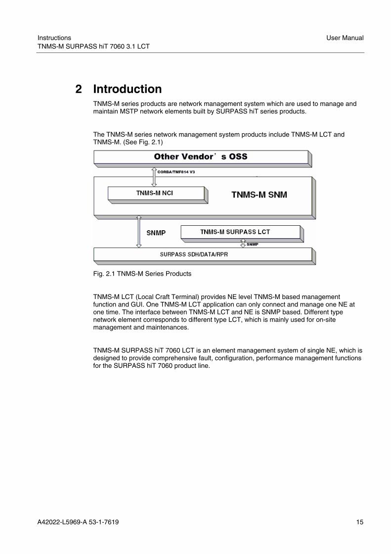
2 Introduction TNMS-M series products are network management system which are used to manage and maintain MSTP network elements built by SURPASS hiT series products.
The TNMS-M series network management system products include TNMS-M LCT and TNMS-M. (See Fig. 2.1)
Fig. 2.1 TNMS-M Series Products
TNMS-M LCT (Local Craft Terminal) provides NE level TNMS-M based management function and GUI. One TNMS-M LCT application can only connect and manage one NE at one time. The interface between TNMS-M LCT and NE is SNMP based. Different type network element corresponds to different type LCT, which is mainly used for on-site management and maintenances.
TNMS-M SURPASS hiT 7060 LCT is an element management system of single NE, which is designed to provide comprehensive fault, configuration, performance management functions for the SURPASS hiT 7060 product line.

User Manual Instructions TNMS-M SURPASS hiT 7060 3.1 LCT LCT
16 A42022-L5969-A 53-1-7619
3 Features
The main features of TNMS-M SURPASS hiT 7060 LCT features are listed in Tab. 3.1.
Feature Description
Java-Based User Interface • Java-based user interface to connect NEs • Provides Chassis View showing the front faceplate of
the equipment • Color-coded LEDs to indicate NE status
Consistency and Data Synchronization
• Uploads data from the actual NE to update the management information of NE in the LCT
• Ensures all status and data in the LCT are consistent with the actual NE
Network Element Control • Enables NE software updates and download from the LCT
• Redundant images of the embedded software are stored in an NE, one active and one backup which can be switched and activated by LCT
• NE warm reboot and cold reboot can be controlled by LCT
Configuration Management • View/synchronize/delete/modify Circuit-pack attributes
• View/synchronize/modify port attributes • TP configuration and management, including
viewing/synchronizing/modifying TP attributes, TP multiplexing structure configuration
• SDH Cross-Connect configuration and management • Timing configuration and management, including
select timing reference for system clock, modify/view timing reference of NE’s system clock, and configure timing reference for station clock
• Virtual concatenation configuration and management • LCAS configuration • Ethernet VLAN configuration • Ethernet Class of Service configuration • Rapid spanning trees management • Rate limiting configuration of Ethernet port • Broadcast strom control • Multicast management • OSPF parameters configuration • OSI-lite parameters configuration
Protection and Redundancy • Supports Cross-Connect/Timing 1+1 protection management
• Supports Equipment Protection management for E1 • Supports MS-SPRing protection management • Supports MSP protection management • Supports SNCP/I protection management • Supports Ethernet RSTP protection management

Instructions User ManualTNMS-M SURPASS hiT 7060 3.1 LCT
A42022-L5969-A 53-1-7619 17
Feature Description
Performance Management • Supports monitored performance TPs and parameters selection.
• Supports current performance management • Supports history performance management
Maintenance • Loopback Configuration for testing • LED test
OSPF • Supports OSPF parameters query and modification Fault Management • Collects, displays, and manages SURPASS hiT 7060
fault messages (including NE, card, port and TP related)
• Supports color coded alarms to indicate alarm severity level
• Supports active alarm synchronization Event Management • Supports NE related event management Tab. 3.1 Feature List

User Manual Instructions TNMS-M SURPASS hiT 7060 3.1 LCT LCT
18 A42022-L5969-A 53-1-7619
4 Hardware Configuration The TNMS-M SURPASS hiT 7060 LCT software can run on the following Operating Systems:
• Windows XP Professional PC, Desktop or Laptop
The minimum hardware requirement of TNMS-M SURPASS hiT 7060 LCT is listed in Tab. 4.1.
Configuration Hardware Requirement
Windows-Based Computer • 1.6 GHz Pentium-4 Processor • 512M RAM • 1 × 20GB Hard Disk • TP Ethernet 10/100BASE-T Networking Port • Graphic Card with 1024 × 768 resolution (75Hz
refresh for Desktop; 60-Hz refresh for Notebook)
• Color Monitor (17’’ for Desktop; 14’’ TFT for Notebook)
Tab. 4.1 Minimum Hardware Requirement of TNMS-M SURPASS hiT 7060 LCT

Instructions User ManualTNMS-M SURPASS hiT 7060 3.1 LCT
A42022-L5969-A 53-1-7619 19
5 Software Configuration The following operating system and software package are required to install and run the TNMS-M SUPASS hiT 7060 LCT.
• Windows XP Professional operating system
• The TNMS-M SURPASS hiT 7060 LCT software

User Manual Instructions TNMS-M SURPASS hiT 7060 3.1 LCT LCT
20 A42022-L5969-A 53-1-7619
6 Installation
6.1 Route Configuration TNMS-M SURPASS hiT 7060 LCT manages NEs based on TCP/IP addresses. Therefore, the user must set a static route to enable the LCT system to find the NE. Before setting the route, ensure that the console port and the MGMT port of the user’s computer are connected with the peer ports of SURPASS hiT 7060.
TNMS-M SURPASS hiT 7060 LCT only supports NE management by the MGMT port.
1. Click <Start>→<Programs>→<Accessories>→<Communications>→<Hyper Terminal> to open the <New Connection: Hyper Terminal> window. (See Fig. 6.1)
Fig. 6.1 Open Hyper Terminal
i

Instructions User ManualTNMS-M SURPASS hiT 7060 3.1 LCT
A42022-L5969-A 53-1-7619 21
2. In the <Connection Description> window, enter the user name in the <Name> field and click <OK>.
Fig. 6.2 Hyper Terminal--Connection Description
3. In the <Connect To> window, choose <COM1> (the computer’s connected console port) in the <Connect using> drop-down menu and click <OK>.
Fig. 6.3 Hyper Terminal--Connect To

User Manual Instructions TNMS-M SURPASS hiT 7060 3.1 LCT LCT
22 A42022-L5969-A 53-1-7619
4. In the <COM1 Properties> window, click <Restore Defaults> and click <OK>.
Fig. 6.4 Hyper Terminal--COM1 Properties
5. Input a few <Enter> and the CLI interface window will be shown. (See Fig. 6.5) The user name is <root> and the password is none.
WELCOME TO LOGIN
NE Version
Rel 2.0 Build 6.40 ______________________________________________________________
User name: root Password:
Fig. 6.5 CLI Window--Login

Instructions User ManualTNMS-M SURPASS hiT 7060 3.1 LCT
A42022-L5969-A 53-1-7619 23
6. The <Main Menu> will be shown. (See Fig. 6.6) User: root Main Menu 2005-01-01 15:41:28
Node IP: 192.168.16.15 Management Port IP Address: 192.168.12.15 Management Port Subnetwork Mask: 255.255.255.0 Default Gateway for Management Port: 192.168.12.1 Telnet Login: Enabled Please select the sub menu to configure the system, or select exit menu to disconnect from the system. Please enter: (U)ser, (I)p address, telnet (L)ogin, (D)CC, (O)si, osp(F), (T)elnet, e(X)it
Fig. 6.6 Main Menu
7. User Table
Press ‘U’ from the <Main Menu> and the <User Table> will be shown. (See Fig. 6.7). The user table enables the user to add/delete/modify the user information.
User: root ** User Table ** 2005-01-01 15:37:52 User Name Password Timeout(m Access Le Online Logged In Last Acce op ****** 15 Operator false 0 0 root ****** 30 Administr true 56156 56156 Please enter: (G)oto, (R)ight, t(O)p, (D)own, (A)dd, dele(T)e, (E)dit, e(X)it
Fig. 6.7 User Table

User Manual Instructions TNMS-M SURPASS hiT 7060 3.1 LCT LCT
24 A42022-L5969-A 53-1-7619
Press ‘E’ from the <User Table> to edit a given user. User: root ** User Table ** 2005-01-01 15:38:30
User Name root 1) Password ****** 2) Timeout(min.) 30 3) Access Level Administrative Online true Logged In Time 56156 Last Accessed 56156 4) Access EMS true 5) Access Craft true Login Count 1 Please enter: (1-5), (G)oto, t(O)p, (D)own, (A)dd, dele(T)e, (S)ummary, e(X)it
Fig. 6.8 Edit a Given User
8. IP Address Configuration
Press ‘I’ from the <Main Menu> to enter the <IP Address Configuration> window. (See Fig. 6.9) In this window, configure the node IP address, the management port IP address, the management port subnet mask, and the default gateway for the management port.
The user can select 1 to 4 to configure the special IP address based on needs. User: root IP Address Configuration 2005-01-01 15:48:09 1) Node IP: 192.168.16.15 2) Management Port IP Address: 192.168.12.15 3) Management Port Subnetwork Mask: 255.255.255.0 4) Default Gateway for Management Port: 192.168.12.1 Please enter (1-4) or e(X)it
Fig. 6.9 IP Address Configuration

Instructions User ManualTNMS-M SURPASS hiT 7060 3.1 LCT
A42022-L5969-A 53-1-7619 25
9. Click <Start>→<Programs>→<Accessories>→<Command Prompt> to open the <Command Prompt> window, and then use the <route add> command to enter the static route information. For example, enter <route add 192.168.16.243 mask 255.255.255.255 192.168.12.243 –p> to add the static route information into the user’s computer. (See Fig. 6.10)
Fig. 6.10 Add Static Route Information
6.2 Installing the LCT software package After selecting the SURPASS hiT serial products, Siemens post sales engineers and technical support technicians will help to complete selecting and installing hardware and software based on requirements. A TNMS-M SURPASS hiT 7060LCT installation CD will be provided. Install the LCT software package on the provided CD using the wizard mode on any qualified operating system.
To describe how to install the LCT software package, the following example is provided.

User Manual Instructions TNMS-M SURPASS hiT 7060 3.1 LCT LCT
26 A42022-L5969-A 53-1-7619
1. Double-click the icon of TNMS_M_SURPASS_hiT7060_R31_setup.exe. A welcome screen will be shown. (See Fig. 6.11) Then Click <Next>.
Fig. 6.11 Setup Wizard Welcome Screen
2. Accept the default destination location, and click <Next> to continue. (See Fig. 6.12)
Note: The TNMS-M SURPASS hiT 7060 LCT software will be installed by default in the %SystemDrive%\Siemens\hiT7060 folder. (%SystemDrive% specifies the drive letter of the hard disk drive containing the Windows operating system.) For example: If Windows is installed in Drive C, the software will be installed in the C:\Siemens\hiT7060 folder.
Fig. 6.12 Select Destination Location
Instructions User ManualTNMS-M SURPASS hiT 7060 3.1 LCT
A42022-L5969-A 53-1-7619 27
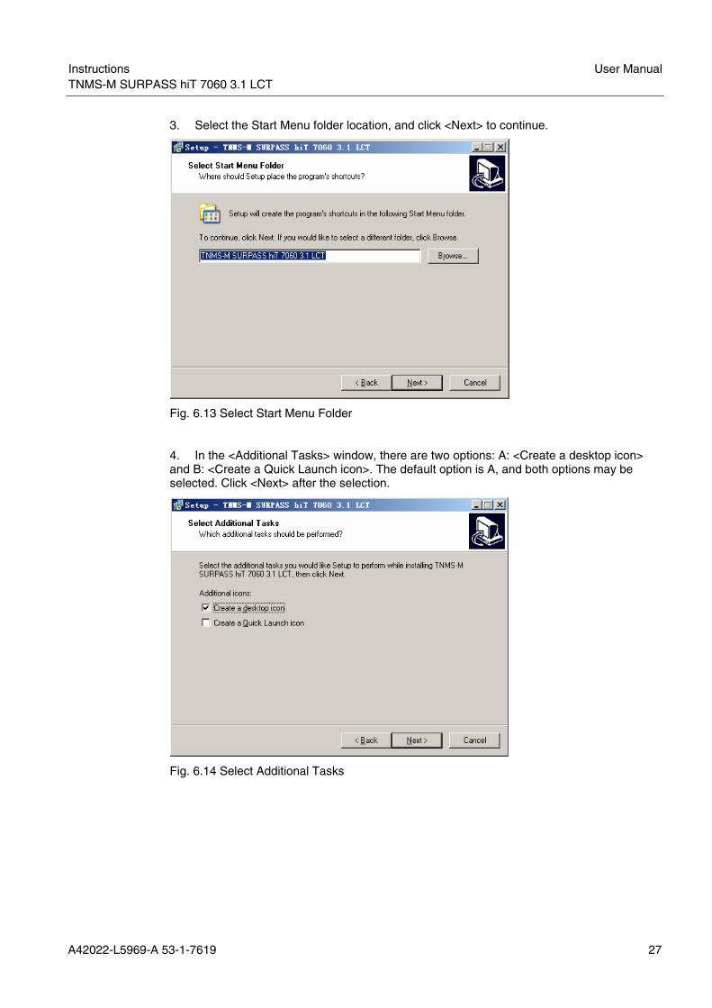
3. Select the Start Menu folder location, and click <Next> to continue.
Fig. 6.13 Select Start Menu Folder
4. In the <Additional Tasks> window, there are two options: A: <Create a desktop icon> and B: <Create a Quick Launch icon>. The default option is A, and both options may be selected. Click <Next> after the selection.
Fig. 6.14 Select Additional Tasks

User Manual Instructions TNMS-M SURPASS hiT 7060 3.1 LCT LCT
28 A42022-L5969-A 53-1-7619
5. After reviewing installation choices, click <Install> to proceed or <Back> to go back to make changes.
Fig. 6.15 Ready to Install
6. LCT will now be installed. (See Fig. 6.16)
Fig. 6.16 Installing

Instructions User ManualTNMS-M SURPASS hiT 7060 3.1 LCT
A42022-L5969-A 53-1-7619 29
7. At any steps of 1-6 above, click <Cancel>, and Exit Setup hint window will pop-up. (See Fig. 6.17) Click <Yes> to exit setup. Click <No> to continue the installation.
Fig. 6.17 Exit Setup
8. Click <Finish> to finish the installation. It is recommended that do not select the option <Launch TNMS-M SURPASS hiT 7060 3.1 LCT>.
Fig. 6.18 Completing the Setup
9. After completing the installation, if the <Create a desktop icon> is selected in the Additional Tasks window, an icon on desktop will be shown.
Fig. 6.19 TNMS-M SURPASS hiT 7060 LCT Desktop Icon
10. Click <Start>, and select <Programs>, <TNMS-M SURPASS hiT 7060 3.1 LCT> or other name typed in step 2 will be seen.

User Manual Instructions TNMS-M SURPASS hiT 7060 3.1 LCT LCT
30 A42022-L5969-A 53-1-7619
Fig. 6.20 Start Menu
11. Click the <TNMS-M SURPASS hiT 7060 LCT> icon and the LCT program will start. During this process, a DOS window will be shown. Wait for a few seconds and a new window will be shown. (See Fig. 6.21) Input LCT’s Login Name, Password and NE’s Node IP Address which can be communicated with. Then click <Connect>.
Note: If the Network adapter of the computer has more than one IP addresses, the LCT program will ask the user to set IP address.
Fig. 6.21 Input NE’s Login Information
12. After successfully connecting to the NE, the following GUI will be shown. (See Fig. 6.22)

Instructions User ManualTNMS-M SURPASS hiT 7060 3.1 LCT
A42022-L5969-A 53-1-7619 31
Fig. 6.22 LCT GUI
6.3 Uninstalling the LCT Software Package 1. Click <Start>, select <Programs>, select <TNMS-M SURPASS hiT 7060 3.1 LCT >, and click <Uninstall TNMS-M SURPASS hiT 7060 3.1 LCT>.
Fig. 6.23 Uninstall TNMS-M SURPASS hiT 7060 LCT
2. Select <Yes> to uninstall TNMS-M SURPASS hiT 7060 3.1 LCT. (See Fig. 6.24)
Fig. 6.24 Confirm Window for Uninstall

User Manual Instructions TNMS-M SURPASS hiT 7060 3.1 LCT LCT
32 A42022-L5969-A 53-1-7619
3: After <Yes> is selected, an Uninstall Status window will be shown. (Fig. 6.25)
Fig. 6.25 Uninstall Status
4. After the uninstalling is complete, a confirm window box will be shown. Click <OK> to finish the uninstall process. Some items could not be removed automatically, but can be removed manually.
Fig. 6.26 Complete Uninstalling Process

Instructions User ManualTNMS-M SURPASS hiT 7060 3.1 LCT
A42022-L5969-A 53-1-7619 33
7 Starting and Shutting down TNMS-M SURPASS hiT 7060 LCT
7.1 Starting TNMS-M SURPASS hiT 7060 LCT After the SURPASS hiT 7060 LCT software is installed, there are two ways to start TNMS-M SURPASS hiT 7060 LCT.
Option 1: Double-click the TNMS-M SURPASS hiT 7060 LCT shortcut on the Desktop;
Option 2: Click <Start>→ <Programs>→<TNMS-M SURPASS hiT 7060 3.1 LCT>.
This will show a login window. A login window will show. After a while, the main window will open. (See Fig. 7.1)
Fig. 7.1 TNMS-M SURPASS hiT 7060 LCT Main Window
7.2 Shutting Down TNMS-M SURPASS hiT 7060 LCT There are two ways to shut down TNMS-M SURPASS hiT 7060 LCT:
Option 1: Click the <X> at top right of the TNMS-M SURPASS hiT 7060 LCT window.
Option 2: From the main menu, click <System>→<Exit>.
A confirm window will be shown. Click <Yes> to confirm the shutdown request.

User Manual Instructions TNMS-M SURPASS hiT 7060 3.1 LCT LCT
34 A42022-L5969-A 53-1-7619
8 Main Interface Features
8.1 Main Window The main window (See Fig. 8.1) consists of the following elements:
• Title Bar
• Main Menu Bar
• Work Area
Fig. 8.1 Main Window
8.1.1 Title Bar
The title bar is located at the top of the main window (See Fig8.1)
The title bar contains:
Leftmost, a special window symbol.
The type designation of the network element.
8.1.2 Main Menu Bar
The main menu bar is located at the top of the main window, below the title bar (See Fig. 8.1). It contains the main menu.
The drop-down menu items will be changed when different object (for example: an NE, a card, or a port) is selected in chassis view.
Before the TNMS-M SURPASS hiT 7060 LCT is connected to the NE, the drop-down menu has only one button shown: <System>, which has two functions: <Connect> and <Exit>.
i
Instructions User ManualTNMS-M SURPASS hiT 7060 3.1 LCT
A42022-L5969-A 53-1-7619 35
System Working with the software Connect Allow t the TNMS-M SURPASS hiT 7060 LCT to connect with NE Exit Close the main window of the NE application software, thus ending the
session
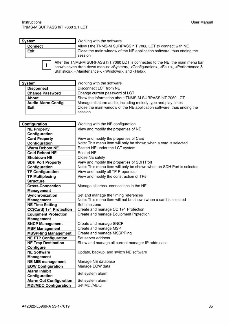
After the TNMS-M SURPASS hiT 7060 LCT is connected to the NE, the main menu bar shows seven drop-down menus: <System>, <Configuration>, <Fault>, <Performance & Statistics>, <Maintenance>, <Windows>, and <Help>.
System Working with the software Disconnect Disconnect LCT from NE Change Password Change current password of LCT About Show the information about TNMS-M SURPASS hiT 7060 LCT Audio Alarm Config Manage all alarm audio, including melody type and play times Exit Close the main window of the NE application software, thus ending the
session
Configuration Working with the NE configuration NE Property
Configuration View and modify the properties of NE
Card Property Configuration
View and modify the properties of Card Note: This menu item will only be shown when a card is selected
Warm Reboot NE Restart NE under the LCT system Cold Reboot NE Restart NE Shutdown NE Close NE safely SDH Port Property
Configuration View and modify the properties of SDH Port Note: This menu item will only be shown when an SDH Port is selected
TP Configuration View and modify all TP Properties TP Multiplexing
Structure View and modify the construction of TPs
Cross-Connection Management
Manage all cross- connections in the NE
Synchronization Management
Set and manage the timing references Note: This menu item will not be shown when a card is selected
NE Time Setting Set time zone CC(Card) 1+1 Protection Create and manage CC 1+1 Protection Equipment Protection
Management Create and manage Equipment Prptection
SNCP Management Create and manage SNCP MSP Management Create and manage MSP MSSPRing Management Create and manage MSSPRing NE FTP Configuration Set server address NE Trap Destination
Configure Show and manage all current manager IP addresses
NE Software Management
Update, backup, and switch NE software
NE MIB management Manage NE database EOW Configuration Manage EOW data Alarm Inhibit
Configuration Set system alarm
Alarm Out Configuration Set system alarm MDI/MDO Configuration Set MDI/MDO
i

User Manual Instructions TNMS-M SURPASS hiT 7060 3.1 LCT LCT
36 A42022-L5969-A 53-1-7619
NE Resource Usage Statistics
View all the cards and ports and their usages
Refresh Chassis View the latest state of NEs Change NE IP Change NE’s IP address
Note: This menu item will not be shown when a card or a port is selected Change Ethernet IP Change Ethernet IP address
Note: This menu item will not be shown when a card or a port is selected OSI Configuration Configure OSI OSPF Manage OSPF Synchronize Card Synchronize a selected card
Note: This menu item will only be shown when a card is selected
Fault Managing Alarm Active Alarms Display current alarm Events Display all events about the operation
Note: This menu item will not be shown when a card or a port is selected Alarm Type List
Management Manage alarm type
Performance and Statistics View the status of NE Current SDH
Performance View and manage current SDH performance
History SDH Performance
View and manage history SDH performance
Current Ethernet Performance
View and manage current Ethernet performance
Ethernet PM Thresholds Set Ethernet performance thresholds History Ethernet
Performance View and manage history Ethernet performance
Maintenance Working with the maintenance test PRBS Test Management Query and set PRBS test Loop-back Test
Management Perform Loop-back test
AIS/RDI Insertion Test Management
Query and set AIS/RDI Insertion test
LED Test Perform LED test
Windows Select the view for the open windows SURPASS hiT 7060
Chassis View List of all the currently-open windows; the selected window (in the foreground) is indicated by the tick
Minimize All Minimizes the opened windows Maximize All Maximizes all windows
Help Online help( in English) conforming to MS Windows Online Help Display the help topics in the form of the <contents>, <Index>, and <Search>
Folders
Tab. 8.1 Main Menu Bar

Instructions User ManualTNMS-M SURPASS hiT 7060 3.1 LCT
A42022-L5969-A 53-1-7619 37
8.1.3 Work Area
This range of the main window (See Fig. 8.1) shows all the windows which have just been opened.
All windows within the work area can be opened or closed without the application software ending (function of Windows).
In the Alarm Count area, all current alarm are collected and the number are listed by serious and category.
8.2 Submenus (with Right Mouse Button Click) The menu sequence which is described here depends on the selected card.
8.2.1 SDH Card
After selecting the STM card, click right button.
Card Property Configuration
Open Card Properties window
Synchronize Card Open Synchronize window Active Alarms View and manage active alarms Cold Reboot Card Restart card
8.2.2 CC Card
After selecting the CC card, click right button.
Card Property Configuration
Open Card Properties window
Synchronize Card Open Synchronize window Active Alarms View and manage active alarms Cold Reboot Card Restart card Cross-Connect Management
Open Cross Connection Management window
Synchronization Management
Open Synchronization Management window
8.2.3 Ethernet Card
After selecting the Ethernet card, click right button.
Card Property Configuration Open Card Properties window Synchronize Card Open Synchronize window Active Alarms View and manage active alarms Delete Card Delete Card

User Manual Instructions TNMS-M SURPASS hiT 7060 3.1 LCT LCT
38 A42022-L5969-A 53-1-7619
9 NE Configuration and Management Before performing actions on the TNMS-M SURPASS hiT 7060 LCT, the LCT must be connected to an NE.
9.1 Chassis View When the TNMS-M SURPASS hiT 7060 LCT is connected to an NE, the NE Chassis View will be shown, which shows the real-time status of the NE. (See Fig. 9.1)
Fig. 9.1 Chassis View
For example, when the sixth card from the right side in Fig. 9.1 was pulled out, the red <Absent> warning will be marked on the card as shown in Fig. 9.1.
In this view, a total representation of the current node status will be shown, including a graphical view of all the slots, the card functions, the card types, the status of individual ports, the power status, and other NE functions. However, one cannot change any properties of this node in the chassis view. Only after opening the configuration window can one start to modify node properties.
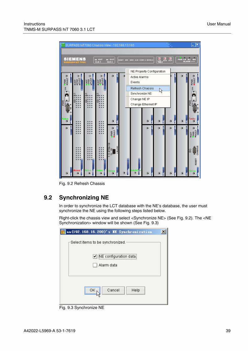
Right-click the chassis view and select <Refresh Chassis> in the pop-up menu (See Fig. 9.2) or select <Configuration>→<Refresh Chassis> to refresh the chassis view.
Instructions User ManualTNMS-M SURPASS hiT 7060 3.1 LCT
A42022-L5969-A 53-1-7619 39
Fig. 9.2 Refresh Chassis
9.2 Synchronizing NE In order to synchronize the LCT database with the NE’s database, the user must synchronize the NE using the following steps listed below.
Right-click the chassis view and select <Synchronize NE> (See Fig. 9.2). The <NE Synchronization> window will be shown (See Fig. 9.3)
Fig. 9.3 Synchronize NE

User Manual Instructions TNMS-M SURPASS hiT 7060 3.1 LCT LCT
40 A42022-L5969-A 53-1-7619
Select the content to synchronize, and click <OK> to start the synchronization process. If the synchronization process succeeds, a message box will be shown.
Click <Cancel> to quit the current window.
Click <Help> to launch the online help.
9.3 NE Property Configuration To open the <NE Properties> window, two methods can be used:
• In the chassis view, right-click and select <NE Property Configuration>.
• From the main menu, select <Configuration>→<NE Property Configuration>.
An <NE Properties> window will be shown. (See Fig. 9.4)
Fig. 9.4 NE Properties
Each item in the window is described in the following table. (See Tab. 9.1)
Item Description
NE Label This is used to distinguish different nodes Serial Number The serial number of this node configured by the manufacturer Location The physical position of this node in real-life System Mode The current system mode of this node (which one cannot modify
from this window). Description The user uses this to field to input his/her own detailed description
of this node

Instructions User ManualTNMS-M SURPASS hiT 7060 3.1 LCT
A42022-L5969-A 53-1-7619 41
Item Description Version The hardware version of this node. Contact The contact or owner of this node Date/Time The current time on this node Card List The simple information of all the cards on this node. The user can
access the card configuration window by double-clicking the corresponding line in the table.
Tab. 9.1 NE Properties
The user can change properties of an NE, but modifications are only completed after the <Apply> button has been clicked.
Click <Refresh> to refresh the information of the window.
Click <OK> to confirm all the modifications and to close the window.
If changing some of the properties, click the <Refresh> button to check the latest status of this node.
Click <Print> to print the information of this node.
Click <Help> to launch the online help.
9.4 Shutting down NE To shut down NE, select <Configuration>→<Shutdown NE> from the main menu. (See Fig. 9.5)
Fig. 9.5 Shutdown NE
i

User Manual Instructions TNMS-M SURPASS hiT 7060 3.1 LCT LCT
42 A42022-L5969-A 53-1-7619
Fig. 9.6 Shutdown Information
Click <Yes> to confirm shutting down this NE. (See Fig. 9.6) The NE that has been shut down will be offline.
9.5 FTP Settings The FTP Settings can get the latest software and data support from the server. To perform The FTP Settings enable the user to get the latest software and data support from the server. To perform NE software management, MIB management, and performance monitoring, the SNM FTP setting needs to be configured first as well as the FTP server.
Use the following steps to apply FTP Settings:
From the main menu, select <Configuration>→<NE FTP Configuration>. The <FTP settings> window will be shown with the current FTP settings. (See Fig. 9.7)
Fig. 9.7 FTP Settings
To modify the current configuration in the <FTP Server Settings> section:
Input the FTP server’s IP address in the <FTP Server IP Address> field.
Input the FTP username in the <UserName> field.
Input the FTP user password in the <Password> field.
To update the current configuration, click <Retrieve>.
Click <Apply> to confirm the modification.
Click <Close> to quit the window. All unsaved modifications will be lost.
Click <Help> to launch the online help.

Instructions User ManualTNMS-M SURPASS hiT 7060 3.1 LCT
A42022-L5969-A 53-1-7619 43
The configuration of the FTP server should be the same as the real FTP server settings. Generally, the LCT server and the FTP server are on the same physical machine.
9.6 NE Software Management Two software images can be stored in the TNMS-M SURPASS hiT 7060 LCT, an active image and a backup image. Using the LCT, the user can download a TNMS-M SURPASS hiT 7060 LCT software image to the NE as the backup version from the FTP server or the user may switch software images between active and backup versions.
NE software management is done by the steps below:
From the main menu, select <Configuration>→<NE Software Management>. The <NE Software Management> window will be shown. (See Fig. 9.8)
Fig. 9.8 NE Software Management
Each field in the window is described as follows. (See Tab. 9.2)
Fields Description
Active Software Version The NE software version currently running
Backup Software Version The backup NE software version
State of Last Command The last command status
Tab. 9.2 NE Software Management Window Field Description
Click <FTP Setting> to open the <FTP setting> window. (See Fig. 9.9)
i

User Manual Instructions TNMS-M SURPASS hiT 7060 3.1 LCT LCT
44 A42022-L5969-A 53-1-7619
Fig. 9.9 FTP Setting
In the <FTP setting> window, choose the NE from the drop-down menu.
Input the corresponding information in the <FTP Server IP Address>, <UserName>, and <Password> fields.
Click <Refresh> to refresh the information.
Click <Apply> to confirm the modifications.
Click <Close> to quit the window. All unsaved modifications will be lost.
Click <Help> to launch the online help.
In the <NE Software Management> window, input the NE software file name on the FTP server in the <Software file name> field, and click <Download from FtpServer> to download the software image to the NE as the backup software version from the FTP server.
To switch the software images between the active version and the backup version, click <Switch>. Then click <Warm Reboot> or <Cold Reboot> to reboot the NE.
Click <Cancel> to close the window. All the unsaved modifications will be lost.
Click <Refresh> to refresh the information.
Click <Help> to launch the online help.
Note: Make sure that the FTP server settings and the software image path are correctly configured before the operation is launched.
9.7 MIB Management The TNMS-M SURPASS hiT 7060 LCT MIB consists of the internal databases/files in the NE that store all the NE configuration and run status information. There are two versions of MIB files stored in the NE: one is the active version and another is a backup version, all the MIB management functions can be performed by using the LCT.
Following the steps below to perform MIB management:
From the main menu, select <Configuration>→<NE MIB Management>. The <MIB Management> window will be shown. (See Fig. 9.10)
i

Instructions User ManualTNMS-M SURPASS hiT 7060 3.1 LCT
A42022-L5969-A 53-1-7619 45
Fig. 9.10 MIB Management
Click <FTP Setting> to open the <FTP setting> window. (See Fig. 9.9)
Fig. 9.11 FTP Setting
In the <FTP setting> window, choose the NE from the drop-down menu.
Input the corresponding information in the <FTP Server IP Address>, <UserName>, and <Password> fields.
Click <Refresh> to refresh the information.
Click <Apply> to confirm the modifications.
Click <Close> to quit the window. All unsaved modifications will be lost.
Click <Help> to launch the online help.
In the <MIB Management> window, to upload the MIB files from the NE to the FTP server, input the directory in which the MIB files will be saved on the FTP server in the <MIB Backup Directory> field, and then click <Upload MIB>.
To download the MIB files from the FTP server to the NE, input the directory in which the MIB files exist in the <MIB Backup Directory> field, and then click <Download MIB>.
To activate the backup MIB version, click <Switch>. This operation will activate the backup MIB version.

User Manual Instructions TNMS-M SURPASS hiT 7060 3.1 LCT LCT
46 A42022-L5969-A 53-1-7619
The <State of Last Command> field shows the state of the last command. Click <Refresh> to get the value of State of Last Command field.
9.8 NE Timing Setting Open the corresponding chassis view.
From the main menu, select <Network>→<NE Time Setting>.
An NE Time Settings window will be shown. (See Fig. 9.12)
Fig. 9.12 NE Time Settings
In the drop-down menu of <Network Time Protocol>, the protocol can be set <Enable> or <Disable>.
In the drop-down menu of <TimeZone>, select local time zone for NE.
In the <Managed NE(active) List> section, select the corresponding NE whose time will be modified.
In the drop-down menu of <Network Element Time>, the current time can be viewed manually.
Click <Retrieve> to check the latest information on setting time.
Click <Apply> to confirm the modifications.

Instructions User ManualTNMS-M SURPASS hiT 7060 3.1 LCT
A42022-L5969-A 53-1-7619 47
Click <Close> to quit the window, all the unsaved modifications will be lost.
Click <Help> to launch the online help
9.9 NE Trap Destination Configuration Select <Configuration> → <NE Trap Destination Configure>. An NE Destination Configuration window will be shown. (See Fig. 9.13)
Fig. 9.13 NE Destination
The function of each button is described as follows:
Click <Apply> to set a selection in the window.
Click <Delete>, a confirm window will be shown.(See Fig. 9.14)
Click <Refresh> to update current NE Destination.
Click <Advance> to enter the <NE Communication Parameters Configure> window. (See Fig. 9.15)
Click <Close> to quit the window without saving any modifications.
Click <Help> to launch the online help.
Fig. 9.14 Confirmation for Delete

User Manual Instructions TNMS-M SURPASS hiT 7060 3.1 LCT LCT
48 A42022-L5969-A 53-1-7619
Fig. 9.15 NE Communication Parameters Configure
9.9.1 Changing NE IP
To change NE IP address of an existing node:
Select <Configuration>→<Change NE IP>
Right click NE and select <Change NE IP> in the pop-up menu. A new window will be shown. (See Fig. 9.16)
Fig. 9.16 Change NE IP
Input the new IP information of the NE, including <Current IP address>, <Current Subnet Mask> and <Current Gateway>.
Click <OK> to confirm the modifications, or select <Cancel> to quit this window.
9.9.2 ChangIng Ethernet IP
Use one of the following two methods to change the Ethernet IP address of an existing node:
• Select <Configuration>→<Change Ethernet IP>, or
• Right click the MGMT port and select <Change Ethernet IP> in the popup menu. And the <Configure Ethernet IP> window will be shown. (See Fig. 9.17)
Fig. 9.17 Configure Ethernet IP

Instructions User ManualTNMS-M SURPASS hiT 7060 3.1 LCT
A42022-L5969-A 53-1-7619 49
Input the new IP information of the NE, including <Current P address> and <Current Subnet Mask>.
Click <OK> to confirm the modifications, or select <Cancel> to quit this window.

User Manual Instructions TNMS-M SURPASS hiT 7060 3.1 LCT LCT
50 A42022-L5969-A 53-1-7619
10 SDH Configuration and Management
10.1 Card Configuration and Management In the chassis view, the card selected becomes framed in blue.
There are two methods to open the card configuration window in chassis view:
• Right-click the card, select <Card Property Configuration>, or
• From the main menu, select <Configuration>→<Card Property Configuration>.
A Card Properties window will be shown. (See Fig. 10.1)
10.1.1 SDH Card Configuration and Management
A typical window for card properties is shown below:
Fig. 10.1 Card Properties
Each field in the window is described as follows. (See Tab. 10.1)
Fields Description
Slot Number The slot this card has been plugged into. Card Function The function of the card. The function of the card will also
be showed in the chassis view, on the right top corner of this card, and in a floating window box after the mouse has been pointing on the card for a while.

Instructions User ManualTNMS-M SURPASS hiT 7060 3.1 LCT
A42022-L5969-A 53-1-7619 51
Fields Description Card Type The type of the card, such as, STM-64, STM-16, STM-4,
STM-1, UDC, GE, FE, MC, CC, etc. Card State The current state of this card Card Serial Number The serial number of this card Card Label This is used to distinguish different cards easily Boot Image Version The version of the boot server
Boot Image Date The time, when the boot server started Card Disable Select yes or no in the drop-down menu Hardware Version The version of this card.
Temperature Threshold The threshold setting for the temperature alarm. When the temperature of this card is over the threshold, an alarm will be raised.
Temperature Clear Threshold
When the temperature has fallen below the temperature clear threshold, the temperature alarm will be automatically cleared.
Port list The list of all ports on this card.
Tab. 10.1 Card Identification
If any properties of a card have been modified, the <Apply> button must be used to validate these changes. And only after clicking this button, will the modification be completed.
When viewing the card options and not changing properties of the card, click <Refresh> to check the latest status of the card.
Click <Print> to print the information on this card.
Click <Close> to close the window. All the unsaved modifications will be lost.
Click <Help> to launch the online help.
10.1.2 Synchronizing the Card
Right-click the corresponding card in the chassis view and select <Synchronize Card>. A synchronize card window will be shown. (See Fig. 10.2)
Fig. 10.2 Synchronize Card
Click <Yes> to start the synchronization process.
Click <No> to cancel the synchronization process.

User Manual Instructions TNMS-M SURPASS hiT 7060 3.1 LCT LCT
52 A42022-L5969-A 53-1-7619
10.1.3 Deleting Card
When the card has an absent status, right-click it. In the pop-up menu, select <Delete Card>. Then click <Yes> in the pop-up warning window to confirm the deletion command, or click <No> to cancel this operation.
10.2 SDH Port Configuration and Management There are two ways to open the port configuration window: • In the chassis view, choose the corresponding port. Right-click, and select <SDH Port
Property Configuration>. • Open the port configuration in the card configuration window: double-click the line of the
port to view or configure in the <Port List>.
A Port Properties window will be shown. (See Fig. 10.3)
Fig. 10.3 Port Properties
There are two parts in this window: <Port Configuration> and <Port Status>. Each parameter in this window is described below. Generally, users can only change some parameters in the Port Configuration part.
10.2.1 Port Configuration
Fields Descriptions
Port Type This identifies the type of port Port Label A user can change this field to distinguish among ports

Instructions User ManualTNMS-M SURPASS hiT 7060 3.1 LCT
A42022-L5969-A 53-1-7619 53
Fields Descriptions Port Mode There are three modes:
<Auto mode>: The system decides the optimum mode for this port. <Monitor mode>: When an alarm is generated from this card, it will be automatically reported to the alarm management. <Non-monitor mode>: No matter how many alarms are generated from this card, none of them will be reported.
Port Admin Mode There are two Port Admin Modes: <Enable> (connected), or <Disable> (unconnected)
Auto Laser Shutdown <Yes> means the laser transmitter will shutdown automatically when the laser receiver detects loss of signal.
Port DCC Mode DCC (Data Communication Channel) is a management and communication channel carried in the SDH frames. Choosing MS-DCC or RS-DCC means that the DCC has been launched, and Off means that DCC is shutdown or unavailable.
Port DCC Protocol There are three port DCC protocols can be chosen: HDLC, PPP, and OSI.
Tab. 10.2 Port Configuration
10.2.2 Port Status
This section displays the SDH port current status.
Fields Descriptions
Operating Status The port status whether it is under operation or not.
Laser Bias Current Value of the laser bias current Received Laser Power
Optical power received through this port. (If the power is low, for example less than -40dBm, the sensor will not show its real number but will show –40)
Transmitted Laser Power
Optical power transmitted out from this port. (If the power is low, for example less than -40dBm, the sensor will not show its real number but show -40)
Laser Temperature Temperature of the laser
Tab. 10.3 Port Status
If any properties of the port have been changed, click <Apply> to confirm them. Only after clicking this button have the modifications been completed.
If no changes are planned as the card has been inspected, click <Refresh> to check the latest status of the port.
Click <Print> to print the information of this port.
Click <Close> to quit the window. All the unsaved modifications will be lost.
Click <Help> to launch the online help.
10.3 E1 Ports Property Configuration Right-click the corresponding card and select <Card Property Configuration>, a <Card Properties> window will be shown. (See Fig. 10.4)

User Manual Instructions TNMS-M SURPASS hiT 7060 3.1 LCT LCT
54 A42022-L5969-A 53-1-7619
Fig. 10.4 Card Properties Then double-click the row of the port to view or configure in the <Port List> section. The <E1 Ports Properties> window will be shown. (See Fig. 10.5)
Fig. 10.5 E1 Port Properties
<Mode> – Can be set as auto, monitored, or non-monitored.
<Port Admin> − Can be set as Enabled, or Disabled.
Click <Retrieve> to check the real-time E1 port properties.
Click <Apply> to accept modifications in the window.

Instructions User ManualTNMS-M SURPASS hiT 7060 3.1 LCT
A42022-L5969-A 53-1-7619 55
Click <OK> to confirm changes and quit the window.
Click <Close> to quit this window without saving any modifications.
Click <Print> to print the information of the E1 Port.
Click <Help> to launch the online help.
10.4 OSI Configuration In the chassis view select one SDH port. From the main menu, select <Configuration>→<OSI Configuration>. The <OSI Configuration> window will be shown. (See Fig. 10.6)
Fig. 10.6 OSI Configuration
Select <User> or <Network> in <Network Side> submenu according current NE’s position.
Select <LAPD in unconfirmed mode> or <LAPD in acknowledged mode> in <AITS> drop-down.
Input corresponding value in other items. The meaning of those parameters is listed below.
<T200>: retransmissions timer. The unit is millisecond
<T203>: maximum time allowed without frames being exchanged. The unit is second
<N200>: maximum number of frame repetition
<Window>: maximum number outstanding I-frames. Window size in AITS mode
<Config Timer>: timer interval. The unit is second.
<TTL>: time to live for a CLNP PDU
<Local NSAP>: the local NSAP address
<Remote NSAP>: the destination NSAP address

User Manual Instructions TNMS-M SURPASS hiT 7060 3.1 LCT LCT
56 A42022-L5969-A 53-1-7619
<Source IP Address>: the source IP address
<Destination IP Address>: the destination IP address
<MTU of the IP_If>: the maximum long of frame.
Click <Refresh> to check the real-time OSI properties.
Click <Apply> to accept modifications in the window.
Click <OK> to confirm changes and quit the window.
Click <Close> to quit the window without saving any modifications.
Click <Help> to launch the online help.
10.5 CC Configuration and Management To manage all cross-connection in the NE, open the CrossConnect Management window, there are two methods to open this window:
• Select <Configuration>→<Cross-Connect Management> in main window.
• Select a Cross-connect device card in the chassis view, and select <Cross-Connect Management> in right-click menu.
The <Cross-Connect Management> window will be shown. (See Fig. 10.7)
Fig. 10.7 Cross-Connect Management
Use this window to query, add, or delete cross-connection.
10.5.1 Querying Current Cross-Connection
Usually there are many Cross-Connections established within one NE. The TNMS-M SURPASS hiT 7060 LCT provides a method of easily viewing them by providing a Query function.
Input querying parameters
There are several selectable parameters to restrict the range of Cross-Connect, including <A/Z Card> (<A/Z Port>), <Z Card> (<Z Port>), <Capacity>, <Circuit Label>, <Direction>, and <Type>.

Instructions User ManualTNMS-M SURPASS hiT 7060 3.1 LCT
A42022-L5969-A 53-1-7619 57
Select these parameters from the drop-down menus to find the Cross-Connect of interest, i.e. the target Cross-Connect.
After choosing a specific Source Card or Sink Card, manually choose the port to restrict the Cross-Connect to a more limited range.
Input a specific Circuit ID to go to those Cross-Connections directly.
Click <Query> to view all Cross-Connections which satisfy the chosen conditions.
When the mouse moves to a Cross-Connection, the tool tips feature will be shown.
Click <Print> to print the information.
Click <Help> to launch the online help.
10.5.2 Adding a New Cross-Connection
Click <Create> to add a Cross-Connection; the <Create Cross-Connect> window will be shown. (See Fig. 10.8)
Fig. 10.8 Create Cross-Connect
Choose the Cards and Ports between which a Cross-Connection is to be created; all available TPs (See Fig. 10.8) will be listed.
Click <SortByTributary> to sort the TPs in the list by tributary, and then button will be changed to <SortByTimeslot>.
Click <SortByTimeslot> to sort the TPs in the list by timeslot, and then the button will be changed to <SortByTributary>.
Choose the source and the destination TPs, and click <Apply>.

User Manual Instructions TNMS-M SURPASS hiT 7060 3.1 LCT LCT
58 A42022-L5969-A 53-1-7619
The <Apply> and <OK> buttons can only be used if two available ports have been selected.
Click <Apply> to confirm the addition without closing the window and allowing additional cross-connections to be made.
Click <OK> to confirm the changes and close the window.
Click <Cancel> to exit the <Create Cross-Connect> window.
Click <Help> to launch the online help.
10.5.3 Deleting a Connection
In the <Cross-Connection Management> window, cross-connections can be selectively deleted.
Click <Delete>, a warning window will be shown.
Fig. 10.9 Confirmation for deleting Cross-Connections
• Click <Yes> to confirm the deletion.
• Click <No> to cancel the deletion.
10.6 TP Configuration and Management
10.6.1 Querying Current Terminal Point
Select <Configuration>→<TP Configuration>.
The <TP Configuration> window will be shown. (See Fig. 10.10)

Instructions User ManualTNMS-M SURPASS hiT 7060 3.1 LCT
A42022-L5969-A 53-1-7619 59
Fig. 10.10 TP Configuration (View 1 - As Presented)
Select the <Card> and <Port> to be checked, or select All STM, UDC, ATM, and E1 Cards or All STM, VS TM, and E1 Ports to check all the TPs on cards and ports.
Click <Query> to check the TPs. (See Fig. 10.11)
Fig. 10.11 TP Configuration (View 2 - Engaged)

User Manual Instructions TNMS-M SURPASS hiT 7060 3.1 LCT LCT
60 A42022-L5969-A 53-1-7619
Select and view the TP to be modified and make desired changes to TP properties. The properties of this TP will be showed in the right panel.
Every parameter is described in the table below.
Fields Descriptions
TP Alarm Mon Can be set as Monitored or Non-Monitored TIM Enable Can be set as permitted or prohibited TI Trans Mode Can be set as 16-byte, Fixed 1-byte, Provisioned 1-byte TI Rec Mode Can be set as 16-byte, Fixed 1-byte, or provisioned 1-byte
Transmitted TI Shows the transmitted TI Accepted TI Shows the accepted TI Expected TI Shows the expected TI, cannot be changed SL Enabled Can be set as Yes or No Transmitted SL Shows the transmitted SL Accepted SL Shows the accepted SL Expected SL Can be set to various values. DEO Enable Can be set as permitted or prohibited. DEO Threshold The value can be set between 10exp(-5) and 10exp(-9) EXC Enable Can be set as permitted or prohibited. EXC Threshold The value can be set between 10exp(-3) and 10exp(-5)
Tab. 10.4 TP Management Parameters
If any TP properties have been changed, the <Apply> button will be presented enabling its use. Only after clicking the <Apply> button will the modifications be completed.
Click <Print> to send the TP information to a file or a printer.
Click <Close> to quit the window. All unsaved modifications will be lost.
Click <Help> to launch the online help.
10.6.2 TP Multiplexing Structure
To open TP mapping, select <Configuration>→<TP Multiplexing Structure>.
The <TP Multiplexing Structure> window will be shown. (See Fig. 10.12)
Fig. 10.12 TP Multiplexing Structure Query
Select the corresponding Card and then Port. Then click <Query> to view the TP Multiplexing Structure for the selected port. (See Fig. 10.13)

Instructions User ManualTNMS-M SURPASS hiT 7060 3.1 LCT
A42022-L5969-A 53-1-7619 61
Fig. 10.13 TP Multiplexing Structure, View 1
Click the circle with a horizontal line to expand the tree, Click the circle with the vertical line to collapse the tree. Use a right-click on the point and choose Expand to open only this branch or Expand All to open all the branches including the sub-branches. (See Fig. 10.14)
Fig. 10.14 TP Multiplexing Structure, View 2
The point color indicates its status: blue color indicates that this point is vacant and the brown color indicates it is occupied.
If the TP is unused, it can be mapped by highlighting and right-clicking the point. (See Fig. 10.15)

User Manual Instructions TNMS-M SURPASS hiT 7060 3.1 LCT LCT
62 A42022-L5969-A 53-1-7619
Fig. 10.15 Add Mapping
After modifications of all the mappings are finished, click <Apply> to confirm the modification.
To check the real-time mapping information, click <Query> at anytime.
Click <Cancel> to exit the <TP Multiplexing Structure> window.
10.7 Synchronization Management The TNMS-M SURPASS hiT 7060 LCT supports four timing references: listed from Reference1 to Reference4. Each reference can be configured as an STM-N, TimeIN1, and TimeIN2. Each of the references has 4 levels of priority.
• Right-click the CC Card, and select <Synchronization Management>, or
• Select <Configuration>→<Synchronization Management>
The <Synchronization Management> window will be shown. (See Fig. 10.16)

Instructions User ManualTNMS-M SURPASS hiT 7060 3.1 LCT
A42022-L5969-A 53-1-7619 63
Fig. 10.16 Synchronization Management
10.7.1 Global Settings
Click <Global Settings> to open the Global Settings of the Synchronization Management. (See Fig. 10.17)
Fig. 10.17 Global Settings
Select an option in the drop-down menu.
<QL Mode> enables quality level available or not.
Click <Refresh> to check the real-time status.
Click <Apply> to accept modifications.
Click <Close> to quit the window without saving any modifications.
Click <Help> to launch the online help.

User Manual Instructions TNMS-M SURPASS hiT 7060 3.1 LCT LCT
64 A42022-L5969-A 53-1-7619
10.7.2 Configuring the Timing Source of NE
Click <Station Clock Settings> to open the <Clock Settings> window. (See Fig. 10.18) There are four I/O routes in one SURPASS hiT 7060, two <Time IN> ports and two <Time OUT> ports. Switch between them by using two tabs. (See Fig. 10.18, Fig. 10.19, and Fig. 10.20)
Fig. 10.18 Station Clock Settings Reference Time IN
Every field is described in the table below:
Fields Descriptions
Monitored Status Can be set as auto, monitored, or unmonitored
Signal Type Can be set as 2MHz, 2Mbit/s UnFramed, or 2Mbit/s Framed
Sa bit Can be set from Sa4-Sa8
Tab. 10.5 Timing Source Management Time IN Window Parameters
To prevent a loop automatically, check the <Auto Loop Prevention> box.

Instructions User ManualTNMS-M SURPASS hiT 7060 3.1 LCT
A42022-L5969-A 53-1-7619 65
Fig. 10.19 Station Clock Settings Reference Time Out
Set the <station clock parameters> in the drop-down menu under the <Time OUT> tab. The parameters include <Monitored Status>, <Signal Type>, and <Sa bit>.
For the chosen single type, configure the output clock quality including<Output Type>, <Squelch Mode>, and <Threshold>. The <Output QL> will change accordingly.
In the <ClockOut Reference> tab (See Fig. 10.20), configure the reference clock.
Fig. 10.20 Station Clock Settings Reference Time Out (Clock Out Reference)
Click <Apply> to accept modifications in each window.
Click <Refresh> to check the real-time status.
Click <Close> to quit the window without saving any modifications.
Click <Help> to launch the online help.

User Manual Instructions TNMS-M SURPASS hiT 7060 3.1 LCT LCT
66 A42022-L5969-A 53-1-7619
10.7.3 Configuring the System Clock
To configure the system clock, click <System Clock>. (See Fig. 10.16) The <System Clock> window will be shown. (See Fig. 10.21)
Fig. 10.21 System Clock
The Current Reference, The SystemClock State, and Last External Switch Request show the current timing status and configuration.
The Operation Mode indicates the current operation mode of this NE, including:
<Freerunning> – When Synchronization Supply Units and SDH equipment clocks cannot access stored data, or have never had a reference input, they use their own internal clocks to generate the synchronization signal until the network is restored.
<Auto Selection> – The clock has its frequency phase locked to an input reference signal.
<Holdover>– When the quality of the synchronization inputs falls below accepted levels, Synchronization Supply Units and SDH equipment clocks first use stored data to control phase and frequency variations.
Select one of the three options in the <Operation Mode> field, and then click <SetMode> to change the mode. When <AutoSelection> is selected, modify the <Request> and <Reference> settings if <Force> or <Manual> in <Request> has been selected. Click <Switch> to confirm the changes. If the <Request> state is <Clear>, the <Reference> option will be grayed out.
Click <Close> to quit the window.
Click <Help> to launch the online help.
10.7.4 Configuring the Reference
Use <Synchronization Management> window (See Fig. 10.16) to configure the time reference.
Double-click the corresponding time reference, and a <Timing Source Reference Properties> window will be shown. (See Fig. 10.22)

Instructions User ManualTNMS-M SURPASS hiT 7060 3.1 LCT
A42022-L5969-A 53-1-7619 67
Fig. 10.22 Timing Source Reference Properties
In the <Timing Source Reference Properties> window, the current status of the selected timing source is shown.
Check <Lockout> to keep the reference valid.
Check <Monitored> to monitor the reference.
Select the corresponding Priority from 1 (the highest priority) to 4 (the lowest priority).
Select the <QL Provisioned Mode> in the drop-down menu; options include <Auto> or <Provisioning> modes. In the <Auto> mode, the QL cannot be changed, while in the <Provisioning> mode, the QL can be set to a given value.
When setting the <QL Provisioned Mode> to Provisioning, select the desired quality level in the drop-down menu. The QL levels include:
PRC (Primary Reference Clock): A reference frequency standard comprising an ensemble of PRS that provide a reference frequency signal compliant with ITU G.811 or ETSI EN 300 462-6-1. The free run accuracy of PRC must be 10-11.
SSU-A (Quality Level - SSU Transit): One of the SSM codes. This indicates that the clock source is traceable to a transit node SSU and should be indicated using a '0100' code.
SSU-B (Quality Level - SSU Local): One of the SSM codes. This indicates that the clock source is traceable to a local node SSU and should be indicated using a '1000' code.
SEC (Quality Level – SEC): One of the SSM codes. This indicates that the clock source is traceable to an SEC and should be indicated using a '1011' code.
DNU (Quality Level - Do Not Use): One of the SSM codes. Do Not Use for Synchronization code is used to prevent timing loops and is transmitted in the opposite direction on interfaces used to synchronize equipment’s clock denoted by <1111>.
Click <Apply> to confirm the modifications.
Click <Close> to quit the window without saving.

User Manual Instructions TNMS-M SURPASS hiT 7060 3.1 LCT LCT
68 A42022-L5969-A 53-1-7619
10.8 EOW Configuration In chassis view, select <Configuration>→<EOW Configuration> to set the Engineering Order Wire. The <EOW Config> window will be shown. (See Fig. 10.23 )
Fig. 10.23 EOW Config
To disable EOW settings, click the box to the left of the corresponding Disable box.
To enable the EOW, set the correct card, port, and channel.
Click <Refresh> to check the latest information of EOW.
Click <Apply> to confirm the modifications.
Click <Close> to quit the window. All unsaved modifications will be lost.
Click <Help> to launch the online help.
Click <Print> to print the information.

Instructions User ManualTNMS-M SURPASS hiT 7060 3.1 LCT
A42022-L5969-A 53-1-7619 69
11 Ethernet Configuration and Management
11.1 Bridge Configuration Right-click the corresponding Ethernet card and select <Bridge Configuration> in pop-up menu.
The <Bridge Properties> window will be shown. (See Fig. 11.1)
Fig. 11.1 Bridge Properties
The <Bridge Properties> panel can display the current NE, Card name, and the status of the bridge in corresponding items. Click the drop-down menu of <Bridge Mode> to select one type of tag needed. Input a label to help identify this bridge.
Below this window, there are two tables, which list all LAN and WAN ports. Click the tab to change the table between them. After selecting one port, double-click it to see more detail information about this port.
Click <Refresh> to check the latest information.
Click <Apply> to confirm the modification without closing the window.
Click <OK> to confirm the modification if the user wants this window closed.
Click <Cancel> to quit the window. All unsaved changes will be lost.
Click <Print> to print the information of the bridges properties.
Click< Help> to launch the online help.
11.2 LAN Card Configuration and Management LAN card configuration and management is similar to SDH card configuration and management.
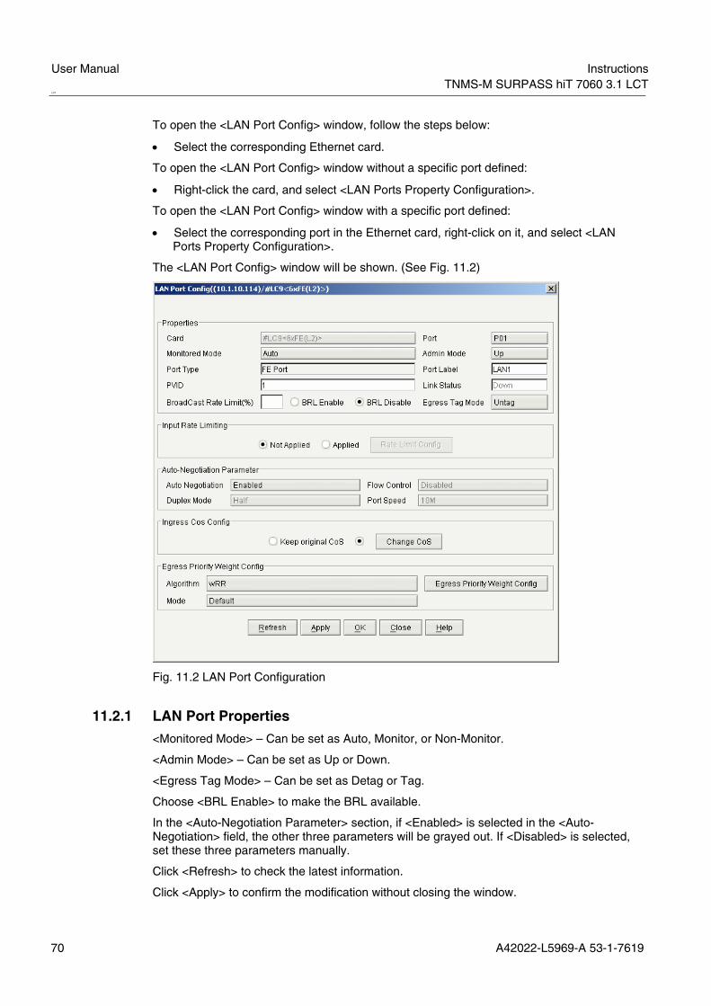
User Manual Instructions TNMS-M SURPASS hiT 7060 3.1 LCT LCT
70 A42022-L5969-A 53-1-7619
To open the <LAN Port Config> window, follow the steps below:
• Select the corresponding Ethernet card.
To open the <LAN Port Config> window without a specific port defined:
• Right-click the card, and select <LAN Ports Property Configuration>.
To open the <LAN Port Config> window with a specific port defined:
• Select the corresponding port in the Ethernet card, right-click on it, and select <LAN Ports Property Configuration>.
The <LAN Port Config> window will be shown. (See Fig. 11.2)
Fig. 11.2 LAN Port Configuration
11.2.1 LAN Port Properties
<Monitored Mode> – Can be set as Auto, Monitor, or Non-Monitor.
<Admin Mode> – Can be set as Up or Down.
<Egress Tag Mode> – Can be set as Detag or Tag.
Choose <BRL Enable> to make the BRL available.
In the <Auto-Negotiation Parameter> section, if <Enabled> is selected in the <Auto-Negotiation> field, the other three parameters will be grayed out. If <Disabled> is selected, set these three parameters manually.
Click <Refresh> to check the latest information.
Click <Apply> to confirm the modification without closing the window.

Instructions User ManualTNMS-M SURPASS hiT 7060 3.1 LCT
A42022-L5969-A 53-1-7619 71
Click <OK> to confirm the modification and close the window.
Click <Cancel> to quit the window. All the unsaved changes will be lost.
Click <Help> to launch the online help.
11.2.2 VLAN Rate Limiting
In the <Lan Port Config> window (See Fig. 11.2), choose <Applied> in the <Input Rate Limiting> section and then click <Rate Limit Config>.
In the <LAN Port Config> window, in the <Input Rate Limiting> area, choose <Applied>, then click the <Rate Limit Config> button.
The <Rate Limit Config> window will be shown. (See Fig. 11.3)
Fig. 11.3 Rate Limit Config
In the <Rate Limit Config> field, <Port+VLAN Based> or <Port Based> can be chosen.
Choose <Port Based>, and input the Rate Limit in the box; the range is from 200k to 100M.
Choose <Port+VLAN Based>, and click the <Port+VLAN Based> button. The <VLAN Rate Limit Config> window will be shown. (See Fig. 11.4)
Click <Apply> to confirm the modifications.
Click <OK> to confirm the modifications and quit this window.
Click <Close> to quit this window. All the unsaved modifications will be lost.
Click <Help> to launch the online help.

User Manual Instructions TNMS-M SURPASS hiT 7060 3.1 LCT LCT
72 A42022-L5969-A 53-1-7619
Fig. 11.4 VLAN Rate Limit Config
All the VLAN Rate Limit information will be displayed in the <VLAN Rate Limit Config> window.
Click <Add> to create a new VLAN Rate Limit. (See Fig. 11.5)
Click <Delete> to delete the selected VLAN Rate Limit.
Click <Modify> to modify the selected VLAN Rate Limit.
Click <Refresh> to check the latest information.
Click <Close> to quit this window. All the unsaved modifications will be lost.
Click <Help> to launch the online help.
Fig. 11.5 Add VLAN Rate Limit

Instructions User ManualTNMS-M SURPASS hiT 7060 3.1 LCT
A42022-L5969-A 53-1-7619 73
In the <Add VLAN Rate Limit> window, input the ID of VLAN in the <VLAN ID> field.
In the <Rate Limit> dropdown menu, select the corresponding rate for this VLAN. And the rate can be set as: 256K, 512K, 1024K, and 2048K, 10M, 20M, 50M and 100M. The operator can also input other rate; the range is from 200k to 100M.
Click <Apply> to confirm the modifications and continue adding VLAN Rate Limit.
Click <OK> to confirm the modifications and quit this window.
Click <Close> to quit this window. All the unsaved modifications will be lost.
Click <Help> to launch the online help.
11.2.3 CoS Configuration
In the <LAN Port Config> window (See Fig. 11.2), select <Change Cos> in the <Ingress Cos Config> field and the <Change CoS> button will be available. Click the button and the <Change CoS> window will be shown. (See Fig. 11.6)
Fig. 11.6 Change Cos
In the <Change Cos> field, <Port+VLAN Based> or <Port Based> can be chosen.
Choose <Port Based>, and set the corresponding rate in the drop-down menu. There are four classes can be set: <Lowest>, <Low>, <High>, and <Highest>.
Choose <Port+VLAN Based>, and click the <Port+VLAN Based> button. The <VLAN+Port Cos Config> window will be shown. (See Fig. 11.4)
Click <Apply> to confirm the modifications.
Click <OK> to confirm the modifications and quit this window.
Click <Close> to quit this window. All the unsaved modifications will be lost.
Click <Help> to launch the online help.

User Manual Instructions TNMS-M SURPASS hiT 7060 3.1 LCT LCT
74 A42022-L5969-A 53-1-7619
Fig. 11.7 VLAN+Port Cos Config
All the VLAN Cos information will be displayed in the <VLAN+Port Cos Config> window.
Click <Add> to create a new VLAN Cos. (See Fig. 11.5)
Click <Delete> to delete the selected VLAN Cos.
Click <Modify> to modify the selected VLAN Cos.
Click <Refresh> to check the latest information.
Click <Close> to quit this window. All the unsaved modifications will be lost.
Click <Help> to launch the online help.
Fig. 11.8 Add VLAN Cos
In the <Add VLAN Cos> window, input the ID of VLAN in the <VLAN ID> field.

Instructions User ManualTNMS-M SURPASS hiT 7060 3.1 LCT
A42022-L5969-A 53-1-7619 75
In the <Cos> dropdown menu, select the corresponding rate for this VLAN. There are four classes can be set: <Lowest>, <Low>, <High>, and <Highest>.
Click <Apply> to confirm the modifications and continue adding VLAN Cos.
Click <OK> to confirm the modifications and quit this window.
Click <Close> to quit this window. All the unsaved modifications will be lost.
Click <Help> to launch the online help.
11.3 WAN Port Configuration To configure WAN Ports, select the corresponding Ethernet card.
Right-click the card and select <Wan Ports Property Configuration>, the <WAN Port Config> window will be shown. (See Fig. 11.9)
Fig. 11.9 WAN Port Config
Select the port to modify in the <Port> drop-down menu.
The settings of the <Properties> and <Ingress Cos Config> sections in this window are the same as that in the <LAN Port Config> window.
In the <Bandwidth Management> panel, enable or disable LCAS and then click <Bandwidth Management> for detailed settings. (See Fig. 11.10)

User Manual Instructions TNMS-M SURPASS hiT 7060 3.1 LCT LCT
76 A42022-L5969-A 53-1-7619
Fig. 11.10 Bandwidth Configuration
For example, to set bandwidth to 4Mb, choose VC12-1 and VC12-2 (Other AUGs can be chosen from the left table) by clicking <⇒>.
Click <Apply> to confirm the modification without closing the window.
Click <OK> to confirm the modification with this window closed.
Click <Close> to quit the window. All the unsaved changes will be lost.
Click <Help> to launch the online help.
11.4 VLAN Management Select the corresponding Ethernet card, right-click, and select <VLAN Management>. A new window of <VLAN Management> will be shown. (See Fig. 11.11)
In the <Query Condition> section, fill in the conditions as needed.
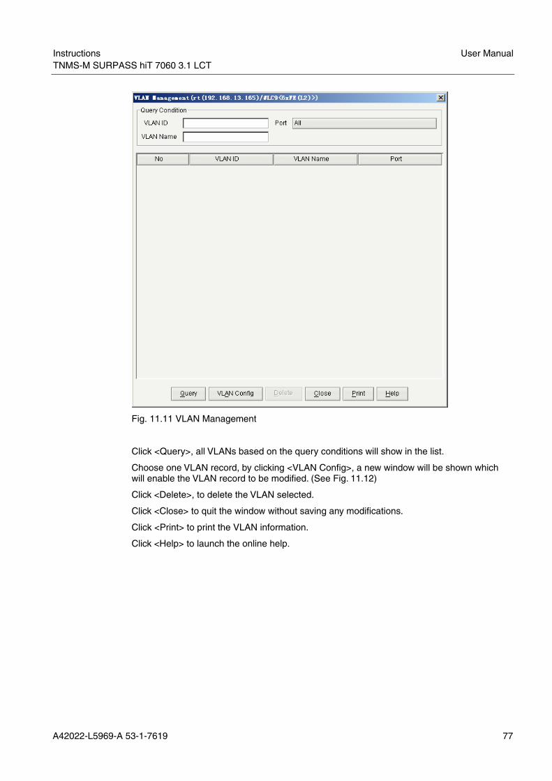
Instructions User ManualTNMS-M SURPASS hiT 7060 3.1 LCT
A42022-L5969-A 53-1-7619 77
Fig. 11.11 VLAN Management
Click <Query>, all VLANs based on the query conditions will show in the list.
Choose one VLAN record, by clicking <VLAN Config>, a new window will be shown which will enable the VLAN record to be modified. (See Fig. 11.12)
Click <Delete>, to delete the VLAN selected.
Click <Close> to quit the window without saving any modifications.
Click <Print> to print the VLAN information.
Click <Help> to launch the online help.

User Manual Instructions TNMS-M SURPASS hiT 7060 3.1 LCT LCT
78 A42022-L5969-A 53-1-7619
Fig. 11.12 Modify VLAN Based on VLAN
Use the <Based on VLAN> tab to reset VLAN ID and VLAN Name, and to select ports.
Click <Apply> to set modifications in the window.
Click <OK> to confirm changes and quit the window.
Click <Close> to quit the window without saving any modifications.
Click <Help> to launch the online help.
Use the <Based on Ports> tab to modify the VLAN List. (See Fig. 11.13)

Instructions User ManualTNMS-M SURPASS hiT 7060 3.1 LCT
A42022-L5969-A 53-1-7619 79
Fig. 11.13 Modify VLAN Based on Ports
11.5 Static MAC Address Configuration To configure Static MAC Address, select the corresponding Ethernet card.
Right-click and click <Static MAC Address Configuration>.
The <Static MAC Address Config> window will be shown. (See Fig. 11.14) The VLAN Ids and Ports of all the MAC Addresses will be listed in this window.

User Manual Instructions TNMS-M SURPASS hiT 7060 3.1 LCT LCT
80 A42022-L5969-A 53-1-7619
Fig. 11.14 Static MAC Address Configuration
Select the corresponding MAC; click <Delete> to delete existing MAC.
To add a new MAC Address, click <Add>. An <Add MAC Address> window will be shown. (See Fig. 11.15)
Fig. 11.15 Add MAC Address
Input the <MAC Address>.
Input the <VLAN ID> and select the corresponding port in the drop-down menu.
Click <Apply> to confirm the action and continue adding other MAC Address.
Click <OK> to confirm the action and close the window.
Click <Close> to quit the window, all unsaved modifications will be lost.

Instructions User ManualTNMS-M SURPASS hiT 7060 3.1 LCT
A42022-L5969-A 53-1-7619 81
Click <Help> to launch the online help.
11.6 ACL Configuration ACL (Access Control List) is used to manage MAC can access the Ethernet.
Select the corresponding Ethernet card, right-click, and select <ACL Configuration>. A new window of <ACL Config> will be shown. (See Fig. 11.16)
Fig. 11.16 ACL Config
Click <Add>, a new window will be shown and new ACL may be added in it. (See Fig. 11.17)
Click <Delete>, the chosen ACL will immediately be deleted.
Click <Close> to quit the window without saving any modifications.
Click <Help> to launch the online help.
Fig. 11.17 Add ACL

User Manual Instructions TNMS-M SURPASS hiT 7060 3.1 LCT LCT
82 A42022-L5969-A 53-1-7619
11.7 Group Broadcast Configuration To configure Group Broadcast, select the corresponding Ethernet card.
Right-click, and select <Group Broadcast Configuration>.
The <Group Broadcast Config> window will be shown. All MAC Addresses and Port Settings will be listed in this window. (See Fig. 11.18)
Fig. 11.18 Group Broadcast Configuration
To delete a MAC Address, select the corresponding MAC and click <Delete>.
To add a new MAC Address, click <Add>. A new <Add GroupBroadcast> window will be shown. (See Fig. 11.19)

Instructions User ManualTNMS-M SURPASS hiT 7060 3.1 LCT
A42022-L5969-A 53-1-7619 83
Fig. 11.19 Add MAC Address
Input the MAC Address.
Select the port in the <Available Ports> panel, and click the < > button, to add it to the <Select Ports> field.
Click <Apply> to confirm the action and continue adding other MAC Addresses.
Click <OK> to confirm the action and close the window.
Click <Close> to quit the window. All the unsaved modifications will be lost.
Click <Help> to launch the online help.
11.8 RSTP Configuration Select the corresponding Ethernet card, right-click, and select <RSTP Configuration>. A new window, <RSTP Properties Configuration>, will be shown. (See Fig. 11.20)

User Manual Instructions TNMS-M SURPASS hiT 7060 3.1 LCT LCT
84 A42022-L5969-A 53-1-7619
Fig. 11.20 RSTP Properties Configuration
In the window, modify the <Max Age>, <Switch Priority>, <Forward Delay>, and <Hello Time> options.
Click <Refresh> to check the real-time port RSTP properties.
Click <Apply> to set modifications in the window.
Click <OK> to confirm changes and quit the window.
Click <Cancel> to quit the window without saving any modifications.
Click <Print> to print the information of RSTP Properties.
Click <Help> to launch the online help.
Double-click a row to view the port RSTP properties. (See Fig. 11.21)
Fig. 11.21 Port RSTP Configuration
In the window, modify <Port Priority>, <Path Cost>, and set <Port Enable> to Disabled or Enabled.

Instructions User ManualTNMS-M SURPASS hiT 7060 3.1 LCT
A42022-L5969-A 53-1-7619 85
12 Protection Management TNMS-M SURPASS hiT 7060 LCT supports CC 1+1, SNCP, and MSP management.
12.1 CC 1+1 Protection Open the chassis view of an NE, in this configuration it will have 2 CC cards. From the main menu, select <Configuration>→<CC(Card) 1+1 Protection>. The <CC 1+1 Protection> window will be shown. (See Fig. 12.1)
Fig. 12.1 CC 1+1 Protection
The status of the two CC cards, CC1 and CC2, are displayed in the upper panel.
In the <Switch Request> drop-down menu, select the corresponding command including: <Clear>, <Force switch to CC1>, <Force switch to CC2>, <Manual switch to CC1> and <Manual switch to CC2>.
Click <Apply> to execute the switch request.
Click <Refresh> to view the latest information.
Click <Close> to quit the window. All the unsaved modifications will be lost.
Click <Help> to launch the online help.
12.2 SNCP Management To open the <SNCP Management> window, select <Configuration>→<SNCP Management> in the main menu.
The <SNCP Management> window will be shown. (See Fig. 12.2)

User Manual Instructions TNMS-M SURPASS hiT 7060 3.1 LCT LCT
86 A42022-L5969-A 53-1-7619
Fig. 12.2 SNCP Management
12.2.1 Viewing and Modifying SNCP
The <Conditions> section in the <SNCP Management> window allows setting the conditions of querying to searching SNCP database. The querying conditions include Label, Card, Port, Capacity, and Direction. Type in the Label of the SNCP to be searched; for the other parameters (Capacity, Card, Direction, and Port), use the drop-down menu provided to set parameters. Click <Query> to start searching the database. The results will be shown as shown in the table below.
The SNCPs and their properties will be shown in the table.
Double-click an SNCP or select one SNCP then click <View/Modify> to view and modify it. (See Fig. 12.3)

Instructions User ManualTNMS-M SURPASS hiT 7060 3.1 LCT
A42022-L5969-A 53-1-7619 87
Fig. 12.3 View/Modify SNCP
The SNCP Properties supported are listed in Tab. 12.1 below.
Items Description
Capacity The transmission capacity. It cannot be modified in the View/Modify window
Direction The transmission direction. It cannot be modified in the View/Modify window.
Restore Mode The restore mode of this protection plan which includes Revertive and No Revertive.
Wait To Restore Time The time interval waited for restore. This number must be between 60 and 720.
Label A label chosen by the user to help the user remember SNCPs conveniently
Hold off Time The time to hold off. This time must be between 0 and 100.
Tab. 12.1 SNCP Properties
<Source/Destination TP> denotes the source node and the destination node of the TP.
<Working TP> – Select the current working TP, including its protection card, port, and TP. This cannot be modified in the <View/Modify> window.

User Manual Instructions TNMS-M SURPASS hiT 7060 3.1 LCT LCT
88 A42022-L5969-A 53-1-7619
<Protection TP> – Select the protection TP, including its working card, port, and TP. This cannot be modified in <View/Modify> window.
Click <Apply> to confirm the modifications.
Click <Create CC> CC to create a new CC. (See Fig. 12.4)
Click <Close> to quit window. All the unsaved modifications will be lost.
Click <Help> to launch the online help.
Fig. 12.4 Create Cross-Connect
12.2.2 Creating SNCP
In the <SNCP Management> window, click <Create> to create a new SNCP. (See Fig. 12.5)

Instructions User ManualTNMS-M SURPASS hiT 7060 3.1 LCT
A42022-L5969-A 53-1-7619 89
Fig. 12.5 Create SNCP
12.2.3 Deleting SNCP
In the <SNCP Management> window click <Delete> to delete the selected SNCP.
Fig. 12.6 Delete SNCP

User Manual Instructions TNMS-M SURPASS hiT 7060 3.1 LCT LCT
90 A42022-L5969-A 53-1-7619
12.2.4 Switching SNCP
Click <Switch> in the <SNCP Management> window to switch SNCP. The <SNCP Switch> window will be shown (See Fig. 12.7)
Fig. 12.7 SNCP Switch
Select a command in the <Command List>: Clear, LockOut, Force Switch to Protection, Force Switch to Working, Manual Switch to Protection, and Manual Switch to Working.
Click <Refresh> to check the latest information.
Click <Apply> to start switch.
Click <Close> to quit the window. All unsaved modifications will be lost.
12.3 MSP Management To open the <MSP Management> window:
From the main menu, select <Configuration>→<MSP Management>.
The <MSP Management> window will be shown. (See Fig. 12.8)
Fig. 12.8 MSP Management

Instructions User ManualTNMS-M SURPASS hiT 7060 3.1 LCT
A42022-L5969-A 53-1-7619 91
Input conditions in the text boxes, including: <Group Id>, and <Label>. Select options in the drop-down menus, including: <Switch Direction>, <Operation Mode>, and <Card>.
Click <Query> to query the MS protection.
Click <Property> to check the result. (See Fig. 12.9)
Click <Close> to quit the window. All the unsaved modifications will be lost.
Click <Help> to launch the online help.
Fig. 12.9 Searching Result of Multiplex Section Protection
In the <MSP Management> window, select one MS Protection. The detailed information of this protection will be shown in the right panel. Click <Commands> to start the operation. The <External Commands> window will be shown. (See Fig. 12.10)

User Manual Instructions TNMS-M SURPASS hiT 7060 3.1 LCT LCT
92 A42022-L5969-A 53-1-7619
Fig. 12.10 External Commands
The properties panel includes: Protection Group ID, Protection Group Label, Wait to Restore, Switch Direction, Protection Type, and Operation Mode.
The Status panel includes: Current Working MS, Work MS, Protect MS, Current Request, and Last Command Result.
In the Commands drop-down menu, select one command, and click <Apply> to operate this command. This window will not be closed.
Click <Retrieve> to check the latest information.
Click <OK> to operate this command and close the window.
Click <Close> to quit the window. All the unsaved modifications will be lost.
Click <Help> to launch the online help.
In the <MSP Management> window, click <Create> to create a new protection. The <Create Linear Multiplex Section Protection Group> window will be shown. (See Fig. 12.11)
Fig. 12.11 Create Linear Multiplex Section Protection Group

Instructions User ManualTNMS-M SURPASS hiT 7060 3.1 LCT
A42022-L5969-A 53-1-7619 93
Input <Protection Group Label> and <Wait to Restore> in the corresponding fields and select other options in the drop-down menus.
Click <OK> to create MS Protection and close the window.
Click <Close> to quit the window. All the unsaved modifications will be lost.
Click <Help> to launch the online help.
In the <MSP Management> window,
Click <Delete> to delete the selected protection.
Click <Print> to print the information of the selected protection.
Click <Help> to launch the online help.
12.4 MSSPRING Management LCT provides the function of creating and viewing MSSPRing information.
To open the <MSSPRing Management> window:
From the main menu, click <Configuration> <MSSPRing Management>. The <MSSPRing Management> window will be shown.(See Fig. 12.12)
Fig. 12.12 MSSPRing Management
The <Query Conditions> section in the <MSSPRing Management> window allows setting the conditions of querying to searching MSSPRing database. The querying conditions include <RingId>,<Ring Label>,<East Sides>,<West Sides>, and <Ring Type>. Type in the ring id and ring label of the MSSPRing to be searched; for the other parameters (<East Sides>, <West Sides>, and <Ring Type>), use the drop-down menu provided to set.

User Manual Instructions TNMS-M SURPASS hiT 7060 3.1 LCT LCT
94 A42022-L5969-A 53-1-7619
12.4.1 Creating MSSPRing
Before the user creates a new MSSPRING, he must know the ring topology and link information about this NE.
Follow the steps below to create a new ring with MSSRPing Protection:
Click <Create>. The <Create MS-SPRing Wizard> window will be shown. (See Fig. 12.13)
Fig. 12.13 Set Ring Property
Input a number as <Ring Id> and arbitrary string as <Ring Label>. Click <Next> to set the NEs in the ring.
Note: If the information is incorrect or some items are not inputted, a warning window will be shown. (See Fig. 12.14)
Fig. 12.14 Warning Window

Instructions User ManualTNMS-M SURPASS hiT 7060 3.1 LCT
A42022-L5969-A 53-1-7619 95
The second step is adding NEs to ring. Input NE’s address and click <Add>. This NE will be added in ring. All NEs in the ring are shown in the list below.(See Fig. 12.15) Select one NE listed in the table, and click <Delete> to delete this NE from the ring.
Note: The NE managed in current LCT software must be added; otherwise the next step will not available.
Fig. 12.15 Set NEs in Ring
Click <Next> to configure East and West sides. (See Fig. 12.16) Select East and West card and port in the drop-down menu. Only those available cards and ports are listed. Click <Previous> to return the previous window.
Fig. 12.16 Set East and West Sides

User Manual Instructions TNMS-M SURPASS hiT 7060 3.1 LCT LCT
96 A42022-L5969-A 53-1-7619
Click <Next> to set peer ports. (See Fig. 12.17) Input the correct card slot and port numbers of peer sides. The number must correspond to physical link.
Fig. 12.17 Set Peer East and West Sides
Click <Next> to set NUT.(See Fig. 12.18) If one time slot is selected as NUT, MS-SPRing switching mechanism is disable on this time slot and its protection time slot.
Fig. 12.18 Set NUT

Instructions User ManualTNMS-M SURPASS hiT 7060 3.1 LCT
A42022-L5969-A 53-1-7619 97
Click <Next> to set WTR. (See Fig. 12.19) Input an integer between 60 and 720 as <Wait to Restore Time>.
Fig. 12.19 Set WTR
Click <Finish> to create MSSPRING according the setting information. Now the status of this MSSPRING is disabling.
Click <Enable> to create MSSPRING according the setting information and enable it.
Click <Cancel> to give up creating MSSPRING and all setting information will be lost.
After a MSSPRING is created, it will be listed in <MSSPRing Management> window. (See Fig. 12.20)
Fig. 12.20 MSSPRING List
12.4.2 Modifying MSSPring
Click <Query> to start searching the database. The results will be shown in the <MSSPRing Management> window.

User Manual Instructions TNMS-M SURPASS hiT 7060 3.1 LCT LCT
98 A42022-L5969-A 53-1-7619
Select one MSSPRing, and then click <Details> to view and modify it. (See Fig. 12.21)
Fig. 12.21 MSSPRing Details
Click <Enable> to change the MSSPRing status to “Enable”.
Click <Disable> to change the MSSPRing status to “Disable”.
Click <Modify> to change configuration of this MSSPRing. The steps are similar to creating a MSSPRing.
When an MSSPRing is enabled, the <Command> and <Advanced> buttons are available.
Click <Command> to enter <Command of MS SPRing> window. (See Fig. 12.22)
Fig. 12.22 Command of MS SPRing
In this window, the last switch information can be retrieved.

Instructions User ManualTNMS-M SURPASS hiT 7060 3.1 LCT
A42022-L5969-A 53-1-7619 99
Click <Refresh> to get latest information.
Select <New Command> in the drop-down menu and click <Apply> to perform new command.
The available commands have: <manual switching ring>: This command performs the ring switch for the normal traffic from the working channels to the protection channels for the span between the node at which the command is initiated and the adjacent node to which the command is destined. This switch occurs if the protection channels are not in an SD condition and are not satisfying an equal or higher priority bridge request (including failure of the protection channels).
<forced switching ring>: This command performs the ring switch for normal traffic from the working channels to the protection channels for the span between the node at which the command is initiated and the adjacent node to which the command is destined. This switch occurs regardless of the state of the protection channels, unless the protection channels are satisfying a higher priority bridge request.
<lockout protection>: This command prevents the ring wraps anywhere for any protection activity and prevents using ring switches anywhere in the ring. If any ring switches exist in the ring, this command causes the switches to drop. If there is a span switch for this span, it is dropped. Thus, all ring switching is prevented (and pre-empted), and span switching is prevented only on the locked-out span.
<clear>: This command clears the externally initiated command and WTR at the node to which the command was addressed. The NE-to-NE signaling following removal of the externally initiated commands is performed using the NR code.
The latest launched command is listed in <Last Command> field. The execution result of the latest command is shown in the <Status of last command> field.
There are two types of command execution results: <Command Successful> — launched command succeed
<Command denied> — launched command failed for some reason
Click <Close> to quit the window.
Click <Help> to launch the online help.
Click <Advanced> button in <Msspring Details> window. The <Advanced Configuration> window will be shown. (See Fig. 12.23)
Fig. 12.23 Advanced Configuration
Click <Suspend> to suspend the MSSPRing.
Click <Unsuspend> to un-suspend the MSSPRing.

User Manual Instructions TNMS-M SURPASS hiT 7060 3.1 LCT LCT
100 A42022-L5969-A 53-1-7619
12.4.3 Deleting MSSPRing
In the <MSSPRing Management> window, click <Delete> to delete the selected MSSPRing.(See Fig. 12.24)
Fig. 12.24 Delete MSSPRing
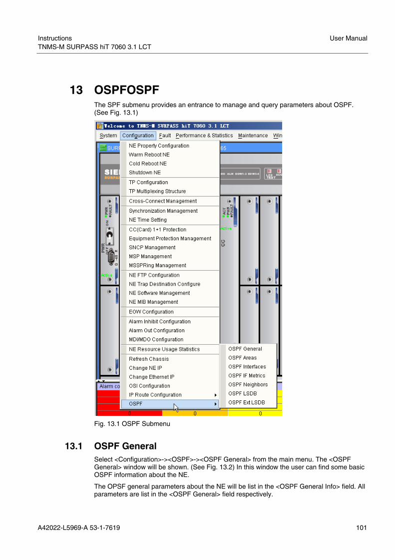
Instructions User ManualTNMS-M SURPASS hiT 7060 3.1 LCT
A42022-L5969-A 53-1-7619 101
13 OSPFOSPF The SPF submenu provides an entrance to manage and query parameters about OSPF. (See Fig. 13.1)
Fig. 13.1 OSPF Submenu
13.1 OSPF General Select <Configuration>-><OSPF>-><OSPF General> from the main menu. The <OSPF General> window will be shown. (See Fig. 13.2) In this window the user can find some basic OSPF information about the NE.
The OPSF general parameters about the NE will be list in the <OSPF General Info> field. All parameters are list in the <OSPF General> field respectively.

User Manual Instructions TNMS-M SURPASS hiT 7060 3.1 LCT LCT
102 A42022-L5969-A 53-1-7619
Fig. 13.2 OSPF General
All parameters and their meaning are list as below:
<Router ID>: A 32-bit integer uniquely identifying the router in the Autonomous System.
<Admin Status>: The administrative status of OSPF in the router. The value <enabled> denotes that the OSPF Process is active on at least one interface; <disabled> disables it on all interfaces.
<Version Number>: The current version number of the OSPF protocol is 2.
<Area Border Router>: A flag to note whether this router is an area border router.
<AS Border Router>: A flag to note whether this router is configured as an Autonomous System border router.
<Extern LSA Count>: The number of external link-state advertisements in the linkstate database.
<Extern LSA Cksum Sum>: The 32-bit unsigned sum of the LS checksums of the external link-state advertisements contained in the link-state database. This sum can be used to determine if there has been a change in a router's link state database, and to compare the link-state database of two routers.
<TOS Support>: the router's support for type-of-service routing.
<Originate New LSAs>: The number of new link-state advertisements that have been originated. This number is incremented each time the router originates a new LSA.
<Rx New LSAs>: the number of link-state advertisements received determined to be new instantiations. This number does not include newer instantiations of self-originated link-state advertisements.
<Ext LSDB Limit>: The maximum number of non-default AS-external-LSAs entries that can be stored in the link-state database. If the value is -1, then there is no limit.
<Multicast Extensions>: A Bit Mask indicating whether the router is forwarding IP multicast (Class D) datagrams based on the algorithms defined in the Multicast Extensions to OSPF. Bit 0, if set, indicates that the router can forward IP multicast datagrams in the router's directly attached areas (called intra-area multicast routing). Bit 1, if set, indicates that the router can forward IP multicast datagrams between OSPF areas (called inter-area multicast routing). Bit 2, if set, indicates that the router can forward IP multicast datagrams between Autonomous Systems (called inter-AS multicast routing).

Instructions User ManualTNMS-M SURPASS hiT 7060 3.1 LCT
A42022-L5969-A 53-1-7619 103
<Exit Overflow Interval>: The number of seconds that, after entering OverflowState, a router will attempt to leave OverflowState. This allows the router to again originate non-default AS-external-LSAs. When set to 0, the router will not leave OverflowState until restarted. We will not support it
<Demand Extensions>: The router's support for demand routing
Click <Edit> to change <Router ID> and < Ext LSDB Limit>.
Click <Refresh> to check the latest information.
Click <Cancel> to give up change.
13.2 OSPF Areas The OSPF Areas data contains information regarding the various areas. The interfaces and virtual links are configured as part of these areas.
Select <Configuration>-><OSPF>-><OSPF Areas> and <OSPF Area> window will be shown. (See Fig. 13.3)
The OPSF Areas parameters about the NE will be list in the <OSPF Aeras> panel. Meantime, the parameters are listed below.
Fig. 13.3 OSPF Area
All parameters and their meaning are list as below:
<Area ID>: A 32-bit integer uniquely identifying an area. Area ID 0.0.0.0 is used for the OSPF backbone
<Auth Type>: The authentication type specified for an area. Additional authentication types may be assigned locally on a per Area basis.
<Import as Extern>: The area's support for importing AS external link-state advertisements. The available values have importExternal(1). importNoExternal (2) and importNssa (3)
<SPF Runs>: The number of times that the intra-area route table has been calculated using this area's link-state database.
<Area Border Router Count>: the total number of area border routers reachable within this area. This is initially zero, and is calculated in each SPF Pass.
<AS Border Router Count>: the total number of Autonomous System border routers reachable within this area. This is initially zero, and is calculated in each SPF Pass.

User Manual Instructions TNMS-M SURPASS hiT 7060 3.1 LCT LCT
104 A42022-L5969-A 53-1-7619
<Area LSA Count>: The total number of link-state advertisements in this area’s link-state database, excluding AS External LSA's.
<Area LSA Cksum Sum>: The 32-bit unsigned sum of the link-state advertisements’ LS checksums contained in this area's link-state database. This sum excludes external (LS type 5) link-state advertisements. The sum can be used to determine if there has been a change in a router's link state database, and to compare the link state database of two routers.
<Area Summary>: controls the import of summary LSAs into stub areas. It has no effect on other areas. If it is <noAreaSummary>, the router will neither originate nor propagate summary LSAs into the stub area. It will rely entirely on its default route. If it is <sendAreaSummary>, the router will both summarize and propagate summary LSAs.
Click <Add> to create a new OSPF area on this NE. Input <Area ID> and select value of <Auth Type>, <Import AS External> and <Area Summary> in the drop-down menus. Other parameters’ value is set automatically. (See Fig. 13.4)
Fig. 13.4 Add OSPF Area
Click <Apply> to add this OSPF area.
Click <Cancel> to give up adding this area.
In the <OSPF Area> window, click <Edit> to configure the OSPF areas on the NE. (See Fig. 13.5)

Instructions User ManualTNMS-M SURPASS hiT 7060 3.1 LCT
A42022-L5969-A 53-1-7619 105
Fig. 13.5 Edit OSPF Area
In the <OSPF Area> window:
Click <Refresh> to check the latest information.
Click <Delete> to delete the selected area.
Click <Close> to close this window.
Click <Help> to launch the online help.
13.3 OSPF Interfaces The <OSPF Interface> window augments the ipAddrTable with OSPF specific information and describes the interfaces from the viewpoint of OSPF.
Select <Configuration>-><OSPF>-><OSPF Interfaces> and the <OSPF Interfaces> window will be shown. (See Fig. 13.6)
The OPSF Interface parameters about the NE will be list in the <OSPF Interfaces> field. Meantime, every parameter is list below.
Fig. 13.6 OPSF Interface
All parameters and their meaning are list as below:

User Manual Instructions TNMS-M SURPASS hiT 7060 3.1 LCT LCT
106 A42022-L5969-A 53-1-7619
<IP Address>: The IP address of this OSPF interface.
<Addressless IF>: for the purpose of easing the instancing of addressed and addressless interfaces; This variable takes the value 0 on interfaces with IP Addresses, and the corresponding value of ifIndex for interfaces having no IP Address.
<Name>: interface name for reference (slot/port)
<Area ID>: A 32-bit integer uniquely identifying the area to which the interface connects. Area ID 0.0.0.0 is used for the OSPF backbone.
<Type>: The OSPF interface type. The available value has <Broadcase(1)>, <NBMA(2)>,<Point To Point(3)>,<Point To Multipoint(5)>,<Loopback(10)>. Broadcast LANs, such as Ethernet and IEEE 802.5, take the value 'broadcast', X.25 and similar technologies take the value <NBMA(2)>, and links that are definitively point to point take the value <Point To Point(3)>.
<Admin Status>: the OSPF interface’s administrative status. The value formed on the interface, and the interface will be advertised as an internal route to some area. The value 'disabled' denotes that the interface is external to OSPF.
<Router Priority>: The priority of this interface. Used in multi-access networks,
<Transit Delay>: The estimated number of seconds it takes to transmit a link state update packet over this interface.
<Retrans Interval>: The number of seconds between link-state advertisement retransmissions, for adjacencies belonging to this interface.
<Hello Interval>: The length of time, in seconds, between the Hello packets that the router sends on the interface.
<Router Dead Interval>: The number of seconds that a router’s Hello packets have not been seen before its neighbors declare the router down.
<Poll Interval>: The larger time interval, in seconds, between the Hello packets sent to an inactive nonbroadcast multi- access neighbor.
<State>: the OSPF Interface State.
<Designated Router>: the IP Address of the Designated Router
<Backup Designated Router>: the IP Address of the Backup Designated Router.
<Events>: The number of times this OSPF interface has changed its state, or an error has occurred.
<Status>: displays the status of the entry. Setting it to 'invalid' has the effect of rendering it inoperative.
<Auth Key>: The Authentication Key
<Multicast Forwarding>: The way multicasts should forwarded on this interface
<Demand>: Indicates whether Demand OSPF procedures (hello suppression to FULL neighbors and setting the DoNotAge flag on proogated LSAs) should be performed on this interface.
<Auth Type>: The authentication type specified for an interface.
Click <Edit> to change the attributes.
Click <Apply> to confirm this change.
Click <Cancel> to give up change.
In <OSPF Interfaces> window:

Instructions User ManualTNMS-M SURPASS hiT 7060 3.1 LCT
A42022-L5969-A 53-1-7619 107
Click <Refresh> to check the latest information.
Click <Close> to close this window.
Click <Help> to launch the online help.
13.4 OSPF Interface Metrics OSPF Interface Metrics describes the metrics to be advertised for a specified interface at the various types of service.
Select <Configuration>-><OSPF>-><OSPF IF Metrics> from the main menu. The <OSPF Interface Metric> window will be shown. (See Fig. 13.7)
The OPSF Interface Metric parameters about the NE will be list in the <OSPF Interfaces> panel. Meantime, every parameter is list below too.
Fig. 13.7 OSPF Interface Metric
All parameters and their meaning are list as below:
<IP Address>: The IP address of this OSPF interface.
<Addressless IF>: For the purpose of easing the instancing of addressed and addressless interfaces; This variable takes the value 0 on interfaces with IP Addresses, and the value of ifIndex for interfaces having no IP Address.
<Type of Service>: The type of service metric being referenced.
<Value>: the metric of using this type of service on this interface. The default value of the TOS 0 Metric is 10^8.
Click <Edit> to change <Value>.
Click <Apply> to confirm this change.
Click <Cancel> to give up change.
In <OSPF Interface Metrics> window:
Click <Refresh> to check the latest information.
Click <Close> to close this window.
Click <Help> to launch the online help.

User Manual Instructions TNMS-M SURPASS hiT 7060 3.1 LCT LCT
108 A42022-L5969-A 53-1-7619
13.5 OSPF Neighbors The OSPF Neighbors describes all neighbors in the locality of the subject router.
Select <Configuration>-><OSPF>-><OSPF Neighors> and <OSPF Neighor> window will pop up. (See Fig. 13.8)
The OPSF neighbors of the NE will be list in the <OSPF Neighbors> panel. Meantime, every parameter is list below too.
Fig. 13.8 OSPF Neighbor
All parameters and their meaning are list as below:
< IP Address >: The IP address this neighbor is using in its IP Source Address.
<AddressLess IF>: On an interface having an IP Address, the value is zero. On addressless interfaces, the value is the corresponding value of if Index in the Internet Standard MIB.
<Router ID>: A 32-bit integer (represented as a type IP Address) uniquely identifying the neighboring router in the Autonomous System.
<Options>: A Bit Mask corresponding to the neighbor's options field. The available value has 0,1,2 and 3. Bit 0 indicates that the system will operate on Type of Service metrics other than TOS 0. Bit 1 indicates that the associated area accepts and operates on external information; Bit 2 indicates that the system is capable of routing IP Multicast datagrams; i.e., that it implements the Multicast Extensions to OSPF.
Bit 3 indicates that the associatedarea is an NSSA.
<Priority>: The priority of this neighbor in the designated router election algorithm. The value 0 signifies that the neighbor is not eligible to become the designated router on this particular network.
<State>: The State of the relationship with this Neighbor.
<Events >: The number of times this neighbor relationship has changed state or an error has occurred.
<LS Retrans Q Len>: The current length of the retransmission queue.
<NBMA Nbr Permanence>: displays the status of the entry.
<HelloSuppressed>: Indicates whether Hellos are being suppressed to the neighbor
Click <Refresh> to view the latest neighbor information.

Instructions User ManualTNMS-M SURPASS hiT 7060 3.1 LCT
A42022-L5969-A 53-1-7619 109
Click <Close> to close this window.
13.6 OSPF LSDB The Link State Database (LSDB) contains the Link State Advertisements from throughout the areas that the device is attached to.
Select <Configuration>-><OSPF>-><OSPF LSDB> and the <OSPF Link State Database> window will be shown. (See Fig. 13.9)
The OPSF link state data of the NE will be list in the <OSPF LSDB> panel. Meantime, every parameter is list below too.
Fig. 13.9 OSPF Link State Database
All parameters and their meaning are list as below:
<Area ID>: The 32 bit identifier of the Area from whichthe LSA was received.
<Type>: The type of the link state advertisement. Each link state type has a separate advertisement format."
<Link State ID>: An LS Type Specific field containing either a Router ID or an IP Address; it identifies the piece of the routing domain that is being described by the advertisement.
<Router ID>: The 32 bit number that uniquely identifies the originating router in the Autonomous System.
<Sequence>: A signed 32-bit integer. It is used to detect old and duplicate link state advertisements. The space of sequence numbers is linearly ordered. The larger the sequence number the more recent the advertisement.
<Age>: The age of the link state advertisement in seconds.
<Checksum>: The checksum of the complete contents of the advertisement, excepting the age field.
<Link State Advertisement>: The entire Link State Advertisement, including its header.
Click <Refresh> to view the latest data.
Click <Close> to close this window.

User Manual Instructions TNMS-M SURPASS hiT 7060 3.1 LCT LCT
110 A42022-L5969-A 53-1-7619
13.7 OSPF Ext LSDB OSPF External Link State Database contains only External Link State Advertisements. The purpose is to allow external LSAs to be displayed once for the router rather than once in each non-stub area.
Select <Configuration>-><OSPF>-><OSPF Ext LSDB> from the main menu and the <OSPF External Link State Database> window will be shown. (See Fig. 13.10)
The OPSF external link state data of the NE will be list in the <OSPF External LSDB> field. Meantime, every parameter is list below too.
Fig. 13.10 OSPF External Link State Database
All parameters and their meaning are list as below:
<Type>: The type of the link state advertisement. Each link state type has a separate advertisement format."
<Link State ID>: An LS Type Specific field containing either a Router ID or an IP Address; it identifies the piece of the routing domain that is being described by the advertisement.
<Router ID>: The 32 bit number that uniquely identifies the originating router in the Autonomous System.
<Sequence>: A signed 32-bit integer. It is used to detect old and duplicate link state advertisements. The space of sequence numbers is linearly ordered. The larger the sequence number the more recent the advertisement.
<Age>: The age of the link state advertisement in seconds.
<Checksum>: The checksum of the complete contents of the advertisement, excepting the age field.
<Link State Advertisement>: The entire Link State Advertisement, including its header.
Click <Refresh> to view the latest data.
Click <Close> to close this window.

Instructions User ManualTNMS-M SURPASS hiT 7060 3.1 LCT
A42022-L5969-A 53-1-7619 111
14 Maintenance
14.1 Loop-back Test Management From the main menu, select <Maintenance>→<Loopback Test Management> to launch the loop back test. (See Fig. 14.1)
Fig. 14.1 Loopback Test
14.1.1 Querying Loopback Status
To view the loopback status of a port, select the corresponding NE, Card, and Loopback Type to be viewed in the drop-down menu. Click <Query> and all ports that satisfy the conditions will be listed in the table.
14.1.2 Setting Loopback Test
Select the corresponding NE, card, and port in drop-down menu to specify which ports to operate loopback testing on. All ports that satisfy the conditions will be listed in the table.
For the desired port, either double-click or highlight and click <Setting> to open the <Loopback Test Configure> window. (See Fig. 14.2)

User Manual Instructions TNMS-M SURPASS hiT 7060 3.1 LCT LCT
112 A42022-L5969-A 53-1-7619
Fig. 14.2 Lookback Test Configure
Choose <Loopback Type>: either <In LoopBack> or <Out LoopBack>.
Click <Begin> to start testing. The <LoopBack Status> line will show the current status.
Click <Stop> to end the test.
Click <Close> to quit the window.
Click <Help> to launch the online help.
14.2 LED Test LED test is used to check if the LEDs of an NE are working correctly.
From the main menu, select <Maintenance>→<LED Test> to launch the <LED Test> window. (See Fig. 14.3)
Fig. 14.3 LED Test
Select the NE to be tested in the drop-down menu and click <OK>. If the LEDs of this NE work correctly, the LEDs will flash for a few moments then go to their normal state.
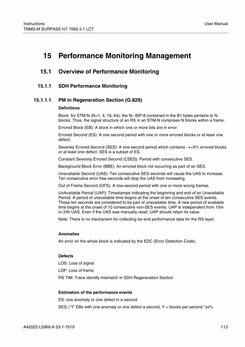
Instructions User ManualTNMS-M SURPASS hiT 7060 3.1 LCT
A42022-L5969-A 53-1-7619 113
15 Performance Monitoring Management
15.1 Overview of Performance Monitoring
15.1.1 SDH Performance Monitoring
15.1.1.1 PM in Regeneration Section (G.829)
Definitions
Block: for STM-N (N=1, 4, 16, 64), the N× BIP-8 contained in the B1 bytes pertains to N blocks. Thus, the signal structure of an RS in an STM-N comprises N blocks within a frame.
Errored Block (EB): A block in which one or more bits are in error.
Errored Second (ES): A one second period with one or more errored blocks or at least one defect.
Severely Errored Second (SES): A one-second period which contains →=X% errored blocks or at least one defect. SES is a subset of ES.
Constant Severely Errored Second (CSES): Period with consecutive SES.
Background Block Error (BBE): An errored block not occurring as part of an SES.
Unavailable Second (UAS): Ten consecutive SES seconds will cause the UAS to increase. Ten consecutive error free seconds will stop the UAS from increasing.
Out of Frame Second (OFS): A one-second period with one or more wrong frames.
UnAvailable Period (UAP): Timestamps indicating the beginning and end of an Unavailable Period. A period of unavailable time begins at the onset of ten consecutive SES events. These ten seconds are considered to be part of unavailable time. A new period of available time begins at the onset of 10 consecutive non-SES events. UAP is independent from 15m or 24h UAS. Even if the UAS was manually reset, UAP should retain its value.
Note: There is no mechanism for collecting far-end performance data for the RS layer.
Anomalies
An error on the whole block is indicated by the EDC (Error Detection Code).
Defects
LOS: Loss of signal
LOF: Loss of frame
RS TIM: Trace identify mismatch in SDH Regeneration Section
Estimation of the performance events
ES: one anomaly or one defect in a second
SES:≥’Y’ EBs with one anomaly or one defect a second, Y = blocks per second *xx%

User Manual Instructions TNMS-M SURPASS hiT 7060 3.1 LCT LCT
114 A42022-L5969-A 53-1-7619
BBE: anomalies but not in SES
Rate STM-0 STM-1 STM-4 STM-16
EBs 800 2,400 2,400 2,400 xx% (EBs) 10% 30% 30% 30%
Tab. 15.1 Regenerator Section SES threshold xx% (for BIP-8)
15.1.1.2 PM in Multiplex Section (G.829)
Definitions
Block: for STM-N (N=1, 4, 16, 64), the N× BIP-8 contained in the B1 bytes pertains to N blocks. Thus, the signal structure of an RS in an STM-N comprises N blocks within a frame.
MS: The N× 24 BIP-1s contained in the B2 bytes of an SDH MS in an STM-N (N=1, 4, 16, 64) pertains to N× 24 in different blocks. Thus, the signal structure of a generic MS comprises N× 24 blocks within a frame.
MS Far End: The count contained in the M1 bytes (M1 and M0 bytes for STM-64) of an SDH MS in an STM-N (N=1, 4, 16, 64) pertains to one block (total of N × 24 different received blocks). Thus, the signal structure of a generic MS (far end) comprises 1 block within a frame.
Errored Block (EB), Errored Second (ES), Severely Errored Second (SES), Constant Severely Errored Second (CSES), Background block error (BBE), Unavailable second (UAS), UnAvailable Period (UAP): refer to the definition for RS.
Anomalies
An Errored Block happens as indicated by an EDC.
Defects Near end defects of Trail termination Applicable Path
MS AIS Multiplex Sections
Tab. 15.2 Defects Resulting in a Near-end Severely Errored Second
Near end defects of Path termination Applicable Path
MS RDI Multiplex Sections
Tab. 15.3 Defects resulting in a Far-end Severely Errored Second
Note: MS AIS means Alarm Indication Signal in Multiplex Sections. MS RDI means Remote Defect Indictor in Multiplex Sections.
Estimation of the performance events
ES: one anomaly or one defect in a second.
SES: ≥’Y’ EBs with one anomaly or one defect a second, Y= (number of blocks per second × xx%).

Instructions User ManualTNMS-M SURPASS hiT 7060 3.1 LCT
A42022-L5969-A 53-1-7619 115
BBE: anomalies but not in SES.
Rate STM-0 STM-1 STM-4 STM-16 STM-64 EBs 9,600 28,800 192,000 921,600 3,686,400 Xx% (EBs) 15% 15% 25% 30% 30%
Tab. 15.4 Multiplex Section SES threshold xx% (For BIP-1)
15.1.1.3 PM for HP/LP (High Order and Low Order Paths) (G.829)
Definitions
Block: for STM-N (N=1, 4, 16, 64), the N× BIP-8 contained in the B1 bytes pertains to N blocks. Thus, the signal structure of an RS in an STM-N comprises N blocks within a frame.
HP: The BIP-8 contained in the B3 byte of an SDH HP pertains to one block. Thus, the signal structure of a generic HP comprises 1 block within a frame. LP VC3s are the same.
HP Far End: The count contained in the G1 byte of an SDH HP pertains to one block. Thus, the signal structure of a generic HP (far end) comprises 1 block within a frame. LP VC3s are the same.
LP: The BIP-2 contained in the V1 byte of an SDH LP pertains to one block. Thus, the signal structure of a generic LP comprises 1 block within a multi-frame.
LP Far End: The FEBE bit contained in the V1 byte of an SDH LP pertains to one block. Thus, the signal structure of a generic LP (far end) comprises 1 block within a multi-frame.
Errored block (EB), Errored Second (ES), Severely Errored Second (SES), Constant Severely Errored Second (CSES), Background block error (BBE), Unavailable second (UAS), UnAvailable Period (UAP): refer to the definition for RS.
Anomalies
An EB happens as indicated by an EDC.
Defects Near end defects of Trail termination Applicable Path
LP UNEQ (Note 2) LP TIM TU LOP TU AIS HP LOM (Note 1) HP PLM
Lower Order Path
HP UNEQ (Note 2) HP TIM AU LOP AU AIS
Higher Order Path
Tab. 15.5 Defects Resulting in a Near-end Severely Errored Second
Note 1: This defect is not related to VC-3.
Note 2: Paths not actually completed, e.g. during path set-up, will contain the unequipped VC-n signal.

User Manual Instructions TNMS-M SURPASS hiT 7060 3.1 LCT LCT
116 A42022-L5969-A 53-1-7619
Near end defects of Path termination Applicable Path
LP RDI Lower Order Path HP RDI Higher Order Path
Tab. 15.6 Defects Resulting in a Far-end Severely Errored Second
Definitions and notes:
LP UNEQ: Lower order Path is UNEQuipped.
LP TIML: Trace identifies mismatch in Lower order Path.
TU LOP: Tributary Unit Loss Of Point.
TU AIS: Tributary Unit Alarm Indictor Signal.
HP LOM: Higher order Path Loss Of Multiframe.
HP PLM: Higher order Path PayLoad Mismatch.
HP UNEQ: Higher order Path UNEQuipped.
HP TIM: Higher order Path Trace Identify Mismatch.
AU LOP: Administrative Unit Loss Of Pointer.
AU AIS: Administrative Unit Alarm Indicator Signal.
LP RDI: Lower order Path Remote Defect.
HP RDI: Higher order Path Remote Defect.
Estimation of the performance events
ES: one anomaly or one defect.
SES: ≥’Y’ EBs with one anomaly or one defect in a second, Y=blocks per second × xx%.
Rate VC-11/12/2 VC-3 VC-4/4c/16c/64c
EBs 600 2,400 2,400 xx% (EBs) 30% 30% 30%
Tab. 15.7 Path Overhead Section SES Threshold xx% (For BIP-2, BIP-8)
15.1.2 Data Performance Monitoring Parameters
The following parameters can be monitored in LCT:
PM Data Parameter
Received Unicast Packets
Received Multicast Packets
Received Broadcast Packets
Received Oversize Packets
Received Undersize Packets
Received Frames in CRC Error
Total Received Bad Packets
Total Received Bad Bytes

Instructions User ManualTNMS-M SURPASS hiT 7060 3.1 LCT
A42022-L5969-A 53-1-7619 117
Total Received Good Packets
Total Received Good Bytes
Sent Unicast Packets
Sent Multicast Packets
Sent Broadcast Packets
Total Sent Good Packets
Total Sent Good Bytes
15.2 SDH Performance Monitoring From the main menu, select <Performance & Statistics>→<Current SDH Performance> to open the <SDH Current Performance> window. This is the main window for the SDH Current Performance. (See Fig. 15.1)
Fig. 15.1 SDH Current Performance
TNMS-M SURPASS hiT 7060 LCT provides the following primary PM management functions (see Tab. 15.8): Functions Description Filter Used to filter and display the points to be examined. This function is only for
the display selection since there are too many points to be displayed clearly. Note: Point is defined as a specific TP, an an example a point could be defined as Node 182.16.1.1, Line Card 1, Port 3, or MS-TTP.
Edit PM parameters for each TP can be edited. Note: If a point is only edited and not filtered, this point will not be displayed. For proper operation, be sure the edited point is filtered first.
Thresholds Only ES, BBE, SES, and UAS have this parameter. If the current value of the parameter crosses the value of the threshold, an alarm will be launched.
Reset Only ES, BBE, and SES have this parameter. If their value crosses the threshold, the crossing threshold alarm will be triggered.
Reset All Resets all values. Print Print or save the PM values.
Tab. 15.8 PM Management Functions

User Manual Instructions TNMS-M SURPASS hiT 7060 3.1 LCT LCT
118 A42022-L5969-A 53-1-7619
15.2.1 Filter Setting
In the <SDH Current Performance> window, click <Filter> to open the <Monitor Point Filter> window, which is used to filter TPs and/or parameters. (See Fig. 15.2)
Fig. 15.2 Monitor Point Filter
15.2.1.1 TP Filter
The filter is used to select TPs that will be shown in the <SDH Current Performance> window. Click <Add> in the <Selected TPs> panel to add a new TP. (See Fig. 15.3) Select an existing point. Click <Remove> to remove the selected TPs.

Instructions User ManualTNMS-M SURPASS hiT 7060 3.1 LCT
A42022-L5969-A 53-1-7619 119
Fig. 15.3 Select Terminal Point
In the <TP Filter> panel, select the point to be monitored by choosing the corresponding node <NE>, <Card>, <Port>, and <TP Type>. This is used to narrow the scope of TPs when searching for specified TPs. In the TP Type combo, the value range is: RS, MS, VC4, and AU4. VC3-TTP and VC12-TTP will be added at later release.
The selected points will be listed in the panel below.
15.2.1.2 Parameter Filter
The parameter filter is used to decide the type of parameters that will be shown in the <Performance Monitored Point> window. A parameter can be fully expressed by a few items: 15-minutes or 24 hours, Near End or Far End, and one or more of the following parameters: ES, BBE, SES, UAS, CSES, OFS, PPJC, NPJC, and UAP.
In the frame, if a checkbox is not selected, all parameters related to the checkbox will not be displayed.
15.2.2 Editing Monitored Parameter
Select <Performance & Statistics>→<Current SDH Performance>. Then click <Edit> in the <SDH Current Performance> window.
The <Edit Properties of Performance Monitor> window is used to edit port, TP, and PM parameters. (See Fig. 15.4)
Fig. 15.4 Edit Properties of Monitored Parameter
This screen is divided to five parts: <Selected TPs>, <Granularity>, <Location>, <Parameter>, and <Setting>.

User Manual Instructions TNMS-M SURPASS hiT 7060 3.1 LCT LCT
120 A42022-L5969-A 53-1-7619
The function of the <Selected TPs> section is the same as the one in the <Monitor Point Filter> window.
The <Granularity> section indicates the performance monitoring granularity.
The <Location> section indicates the PM location.
The <Parameter> section allows the choice of the following parameters to be monitored: ES, BBE, SES, UAS, CSES, OFS, PPJC, and NPJC.
The <Setting> section allows configuration of the performance monitoring and the reports to be provided. There are three options to choose among: UnMon, Mon, and Monitor & Auto-Report.
15.2.3 Alarm Threshold
Select <Performance & Statistics>→<Current SDH Performance>. Then select a row and click <Thresholds> in the <SDH Current Performance> window. The window to configure alarm threshold will be shown. (See Fig. 15.5)
Fig. 15.5 Alarm Threshold
This window is divided to five parts: <Selected TPs>, <Granularity>, <Location>, <Parameter>, and <Setting>.
The function of the <Selected TPs>, <Granularity>, <Location>, and <Parameter> sections are the same as those in the <Edit Properties of Performance Monitor> window. (See Fig. 15.4)
The <Setting> section allows the configuration of Alarm Threshold. If the current value of the parameter crosses the value of the threshold, an alarm will be launched; if the checkbox is not selected, the alarm threshold is disabled.
The value range and default value of 15-minutes and day are listed in the following two tables. (See Tab. 15.9 and Tab. 15.10)

Instructions User ManualTNMS-M SURPASS hiT 7060 3.1 LCT
A42022-L5969-A 53-1-7619 121
TCA Default Value Allowed Range RS ES 114 1-900 RS SES 10 1-900 RS BBE 10 1-65535 MS ES 114 1-900 MS SES 10 1-900 MS BBE 10 1-65535 MS ES (Far End) 114 1-900 MS SES (Far End) 10 1-900 MS BBE (Far End) 10 1-65535 VC4-TTP ES 180 1-900 VC4-TTP SES 15 1-900 VC4-TTP BBE 10 1-65535 VC4-TTP ES (Far End) 180 1-900 VC4-TTP SES (Far End)
15 1-900
VC4-TTP BBE (Far End)
10 1-65535
Tab. 15.9 Default Value and Value Range for a Fixed 15-minute Period
TCA Default Value Allowed Range
RS ES 10,944 1~216-1 RS SES 960 1~216-1 RS BBE 960 1~216-1 MS ES 10,944 1~216-1 MS SES 960 1~216-1 MS BBE 960 1~216-1 MS ES (Far End) 10,944 1~216-1 MS SES (Far End) 960 1~216-1 MS BBE (Far End) 960 1~216-1 VC4-TTP ES 17,280 1~216-1 VC4-TTP SES 1440 1~216-1 VC4-TTP BBE 960 1~216-1 VC4-TTP ES (Far End) 17,280 1~216-1 VC4-TTP SES (Far End) 1440 1~216-1 VC4-TTP BBE (Far End) 960 1~216-1
Tab. 15.10 Default value and Value Range for a Fixed 24-hour Period
15.2.4 History SDH Performance
From the main menu, select <Performance & Statistics>→<History SDH Performance>.
The SDH History Performance is used to display the history value of one parameter of a TP. (See Fig. 15.6)

User Manual Instructions TNMS-M SURPASS hiT 7060 3.1 LCT LCT
122 A42022-L5969-A 53-1-7619
Fig. 15.6 SDH History Performance
The function of <Filter> is the same as that of the <SDH Current Performance> window. (Refer to Chapter 15.2.1.)
15.3 Ethernet Performance Monitoring Configuration In the TNMS-M SURPASS hiT 7060 LCT, the following primary Ethernet PM functions are provided (see Tab. 15.11):
Functions Descriptions
Filter Used to filter and display the points to be examined. This function is only for the display selection since there are too many points to be displayed clearly. Note: Point is defined as a specific LAN or WAN port. For example a Point could be described as Node 182.16.1.1, UDC 1, and LAN port1.
Edit
Ethernet PM parameters for each LAN or WAN port can be edited Note: If a point is only edited and not filtered, this point will not be displayed. For proper operation, be sure the edited point is filtered first.
Reset Use to reset the date . Reset All Used to reset all datum Print Print or save the Ethernet PM values.
Tab. 15.11 Primary Ethernet PM Function
From the main menu, select <Performance & Statistics>→<Current Ethernet Statistics> to open the <Ethernet Current Performance> window. (See Fig. 15.7)

Instructions User ManualTNMS-M SURPASS hiT 7060 3.1 LCT
A42022-L5969-A 53-1-7619 123
Fig. 15.7 Ethernet Current Performance
15.3.1 Filter Setting
The <Monitor Point Filter> window is launched by clicking <Filter> in the <Ethernet Current Performance> window. (See Fig. 15.8)
Fig. 15.8 Monitor Point Filter
This function is the same as the SDH Performance Filter function. Click <Add> to select the port. (See Fig. 15.9)

User Manual Instructions TNMS-M SURPASS hiT 7060 3.1 LCT LCT
124 A42022-L5969-A 53-1-7619
Fig. 15.9 Select Port
Choose a suitable filter parameter from this screen to filter ports: 15-minute or 24-hour and the user’s choice of 15 kinds of Data PM Parameters. These 15 Data PM Parameters have been defined in Chapter 15.1.2.
15.3.2 Editing Monitored Parameter
The <Edit Properties of Performance Monitor> window can be launched by clicking <Edit> in <Ethernet Current Performance> window. (See Fig. 15.10)
Fig. 15.10 Edit Properties of Performance Monitor
There are three frames in this window: <Selected Ports>, <Granularity>, and <Setting>.
<Selected Ports> is used to choose the LAN or WAN ports which to be monitored.

Instructions User ManualTNMS-M SURPASS hiT 7060 3.1 LCT
A42022-L5969-A 53-1-7619 125
<Granularity> allows the choice of a suitable filter parameter: 15 Minutes or 24 Hours.
<Setting> allows choice of port monitor state. There are three options to choose among: <UnMon>, <Mon>, and <Mon & Auto-Report>.
15.3.3 Ethernet PM Thresholds
From the main menu, select <Performance & Statistics>→ <Ethernet PM Thresholds> to open the <1 Second Ethernet Thresholds> window. (See Fig. 15.11)
Fig. 15.11 1 Second Ethernet Thresholds
Click <Filter> to set ports whose threshold to be monitored. (See Fig. 15.12)
Fig. 15.12 Monitor Point Filter
Click <Add> to filter port and add them to the list. (See Fig. 15.13)

User Manual Instructions TNMS-M SURPASS hiT 7060 3.1 LCT LCT
126 A42022-L5969-A 53-1-7619
Fig. 15.13 Select Ports
After selecting the corresponding attributes and clicking <Refresh>, the available ports will be listed. Select ports needed and click <OK>. This action adds those ports in the <Selected Ports> list. (See Fig. 15.14)
Fig. 15.14 Selected Ports
Click <OK> to see those ports’ corresponding thresholds status and values.
In the <1 Second Ethernet Thresholds> window, to modify a port’s thresholds, double-click the corresponding line in the table, or select the line and click <Edit>. This will enter the <Edit Properties of Performance Monitor> window. (See Fig. 15.15)

Instructions User ManualTNMS-M SURPASS hiT 7060 3.1 LCT
A42022-L5969-A 53-1-7619 127
Fig. 15.15 Edit Port Threshold
New monitored ports can be added and those ports’ thresholds scheme and the number of values set can be established. Two thresholds categories are available: <Bad Byte Rate> and <Bad Packet Rate>. The default value for each is 10%. Input any values needed or click <Default> to resume the default value.
Click <Apply> to confirm the settings.
Click <Close> to quit the window.
Click <Help> to launch the online help.
15.3.4 History Ethernet Performance
From the main menu, select <Performance & Statistics>→<History Ethernet Performance>. The <Ethernet History Performance> window will be shown. (See Fig. 15.16)
Fig. 15.16 Ethernet History Performance

User Manual Instructions TNMS-M SURPASS hiT 7060 3.1 LCT LCT
128 A42022-L5969-A 53-1-7619
The function of <Filter> is the same as that of the <Ethernet Current Performance> window. (Refer to Chapter 15.3.1.)
Click <OK> to confirm the modifications.
Click <Cancel> to close the window. All the unsaved modifications will be lost.
Click <Help> to launch the online help.

Instructions User ManualTNMS-M SURPASS hiT 7060 3.1 LCT
A42022-L5969-A 53-1-7619 129
16 Alarm and Event Management
16.1 Overview of Alarms There are five alarm severity level values defined:
• Critical—Service-interrupting alarms.
• Major—Service-affecting alarms.
• Minor—Non-Service-affecting alarms that could potentially become service-affecting. The user needs to inspect the system faults and provide fixes in order to prevent the alarm from deteriorating to Major.
• Warning—Non-Service-affecting alarms. Information is presented to the user for the purpose of maintenance.
• Indeterminate—the alarm severity level is indeterminate.
There are five types of failures in the system:
• Transmission Failure—Failures related to transmission status, such as LOS, LOF, LOP, and LOM.
• Quality of Service Failure—Failure related to system performance, such as response time too long, threshold crossing, and performance degradation.
• Equipment Failure—Failures related to hardware equipment.
• Processing Error Failure—Failures related to software or the fault processing, such as memory overflow, version incompatibility, software errors, program illegal interruption, NE configuration errors an inaccessible NE, AIS, TIM, REI, RDI, PLM, and UNEQ.
• Environmental Failure—Failures related to environment changes, such as unacceptable temperature and humidity, ventilation or cooling system faults, excessive vibration, and door open or closed.
16.2 NE Alarms
16.2.1 Current Alarms
The Current Alarms tab displays all active or unacknowledged alarms, and is updated when a new alarm occurs. Alarms are listed in the order from the oldest to the newest. This window displays the most current alarms (the bottom of the list). Each entry is highlighted with the color associated with its severity. This color coding allows users to perform a quick visual inspection when all alarms are displayed.
When an alarm clears, the date and time when it was cleared is added to the list, and the color is changed to green. However, the alarm remains in the list until it is acknowledged.
Using TNMS-M SURPASS hiT 7060 LCT, the user can:
• Change the alarm list to display different severities or multiple severities
• Sort the alarm list by field
• Acknowledge an alarm
• Clear the alarm list

User Manual Instructions TNMS-M SURPASS hiT 7060 3.1 LCT LCT
130 A42022-L5969-A 53-1-7619
• Refresh the alarm list
• View current alarm and history alarm events from the chassis view
16.2.2 Viewing Active Alarms
To view the active alarms:
Right-click a card, select <Active Alarms> in the pop-up menu. (See Fig. 16.1)
Fig. 16.1 Chassis View with Open Current Alarms
Or, from the main menu, click <Fault> → <Active Alarms> (See Fig. 16.2)
Fig. 16.2 Fault, Active Alarms
To retrieve only the alarms of interest, click on the appropriate icons on the <Alarm count by severity> section in the main window. (See Fig. 16.3)

Instructions User ManualTNMS-M SURPASS hiT 7060 3.1 LCT
A42022-L5969-A 53-1-7619 131
Fig. 16.3 Alarm Count by Severity
The <Active Alarms> window will be shown. (See Fig. 16.4)
Fig. 16.4 Active Alarms
16.2.3 Reviewing the Current Alarms
The information contained in the Active Alarms tab is as follows:
Field or Button Description Severity The severity level of the alarm Category The related category of the specific alarm, including:
Process Error QoS Transmission Equipment
Source The managed object that generates the reported alarm Alarm Message The name of the alarm Raised Time The time the alarm was raised Cleared Time The clear time of the alarm ClearStatus The status of the alarm, including:
Not cleared Cleared Cleared manually
Tab. 16.1 Active Alarms Information
16.2.4 Viewing Alarm Detail
To know more information about one alarm, select this alarm and double-click it. Or select this alarm and click <Detail>. Then the <Alarm Detail> window will be shown. (See Fig. 16.5)
The corresponding description about this alarm will be shown in this window.

User Manual Instructions TNMS-M SURPASS hiT 7060 3.1 LCT LCT
132 A42022-L5969-A 53-1-7619
Fig. 16.5 Alarm Detail
16.2.5 Clearing Alarms
All alarms have a status of either acknowledged or not acknowledged. Once an alarm has been acknowledged and cleared, it will not display in the Current Alarms window. If an alarm is acknowledged but not yet cleared, it remains in the Current Alarms window.
To clear the alarm in the Current Alarms window, right-click the corresponding alarm, and select <Clear Alarm>. (See Fig. 16.6)
The Acknowledge By field value indicates the user who acknowledged the alarm. When the alarm is acknowledged, its color becomes green.
Fig. 16.6 Clear Alarm
16.3 LED Indicators A SURPASS hiT 7060 NE has four LED status indicators that show the operational status of the system.
• PWR (Power)
• CR (Critical Alarm)
• MJ (Major Alarm)
• MIN (Minor Alarm)
These LEDs correspond to the LED status indicators displayed in the chassis view.
The following table describes three LED status indicators.

Instructions User ManualTNMS-M SURPASS hiT 7060 3.1 LCT
A42022-L5969-A 53-1-7619 133
LED name LED Color LED
Status Description
On Power is available to the system. It indicates the presence of the internal power supply after the power conversion.
Power Green
Off Power is not available due to a broken power converter or external power cable or connector.
On The system is either in a booting up stage or in system failure state.
Blinking One or more critical or major alarms are present (for example, service affecting—LOS).
Critical Red
Off No critical or major transmission alarms are present, and the system is in service.
On There are one or more major alarms present. Major Yellow Off No Major alarms. On There are one or more minor alarms present
(non-service affecting). Minor Green
Off No Minor alarms. Note: Warning and indeterminate alarms do not turn on the LED.
Tab. 16.2 LED Status
16.4 Exporting Alarms
16.4.1 Exporting Active Alarms to a File
Before printing or saving alarms to a file, make sure that corresponding alarm ranges have been selected.
To export the active alarm list:
On the menu bar, select <Fault>→<Active Alarm>, and the <Active Alarms> window will display.
Select an alarm row, click <Print>.
The <Print> window will be shown. (See Fig. 16.7)
Fig. 16.7 Report Alarms
Select Paper type.

User Manual Instructions TNMS-M SURPASS hiT 7060 3.1 LCT LCT
134 A42022-L5969-A 53-1-7619
Select <Portrait> or <Landscape>.
Select Output file type. Note: Don’t select <System Printer> here.
Click <OK>.
The <Print Preview> window will be shown. (See Fig. 16.8)
Fig. 16.8 Report Alarms Preview
Click <Print>. The <Save File> window will be shown. (See Fig. 16.9)
Fig. 16.9 Save File
Input the file name in the <File Name> edit box. Click <Save>.
Active Alarms are now successively exported to file.

Instructions User ManualTNMS-M SURPASS hiT 7060 3.1 LCT
A42022-L5969-A 53-1-7619 135
16.4.2 Printing Active Alarms
To print the active alarm list:
On the menu bar, select <Fault> →<Active Alarm>.
The <Active Alarms> window will display.
Right-click the mouse and select <Print Alarm>.
The <Print> window will be shown. (See Fig. 16.10)
Fig. 16.10 Print Alarms
Select Page type.
Select Portrait or Landscape.
Select Output as <System Printer>.
Click <OK>.
The page preview window will be shown. (See Fig. 16.11)
Fig. 16.11 Print Alarms Preview
Click <Print>. The print setup window will be shown. (See Fig. 16.12)

User Manual Instructions TNMS-M SURPASS hiT 7060 3.1 LCT LCT
136 A42022-L5969-A 53-1-7619
Fig. 16.12 Print Setup
Select and set up the printer if necessary, and then click <OK>.
Alarms are now successively printed.
16.5 Configure Fault Management
16.5.1 Audio Alarm Configuration
To configure the Audio Alarm Configuration:
From the main menu, select <System>→<Audio Alarm Config>.
The <Audio Alarm Config> window will be shown. (See Fig. 16.13)
Fig. 16.13 Audio Alarm Configuration

Instructions User ManualTNMS-M SURPASS hiT 7060 3.1 LCT
A42022-L5969-A 53-1-7619 137
Select whether Audio Alarm is enabled or disable.
Set the specific audio file to correspond with the varying alarms.
Choose the Edit the Alarm audio play times.
Click <OK> to confirm the configuration and close the window.
Click <Cancel> to close the window. All the unsaved modifications will be lost.
16.5.2 Alarm Type List Management
By using Alarm Type List Management the user can view and configure alarms.
From the main menu, select <Fault> → <Alarm Type List Management> to enter the <Alarm Type Management> window. (See Fig. 16.14)
Fig. 16.14 Alarm Type List Management
Click <Refresh> to view current alarm type list. In desired, modify the <User Defined Severity> filed or the <Report Status> filed by highlighting a row and right-clicking the corresponding field. (See Fig. 16.15)

User Manual Instructions TNMS-M SURPASS hiT 7060 3.1 LCT LCT
138 A42022-L5969-A 53-1-7619
Fig. 16.15 Modify User Defined Severity of Alarm
Click <Refresh> to view the latest alarm type list.
Click <Apply> to confirm the modifications.
Click <OK> to confirm the changes and close the window.
Click <Close> to quit the window without saving any modifications.
Click <Print> to print the result.
Click <Help> to launch the online help.
16.6 Alarm Configuration for Single NE
16.6.1 Alarm Inhibit Configuration
From the main menu, select <Configuration>→<Alarm Inhibit Configuration>.
The <Alarm Inhibit Configuration> window will be shown. (See Fig. 16.16)
Fig. 16.16 Alarm Inhibit Configuration
Selecting <Node Alarm Inhibit> will stop reporting all node alarms.
Selecting <AIS Alarm Inhibit> will stop using AIS alarms.

Instructions User ManualTNMS-M SURPASS hiT 7060 3.1 LCT
A42022-L5969-A 53-1-7619 139
Selecting <RDI Alarm Inhibit> will stop using RDI alarms
Click <Refresh> to view the latest setting.
Click <Apply> to confirm the setting.
Click <OK> to confirm the changes and quit the window.
Click <Close> to quit the window without saving any modifications.
Click <Help> to launch the online help.
16.6.2 Alarm Out Configuration
From the main menu, select <Configuration>→<Alarm Out Configuration>.
The <Alarm Out Configuration> window will be shown. (See Fig. 16.17)
Fig. 16.17 Alarm Out Configuration
Select <Alarm Out Cutoff> to cutoff alarm out permanently.
Click <Refresh> to view the latest setting.
Click <Apply> to confirm the setting.
Click <OK> to confirm the changes and quit the window.
Click <Close> to quit the window without saving any modifications.
Click <Help> to launch the online help.
16.6.3 MDI/MDO Configuration
From the main menu, select <Configuration>→<MDI/MDO Configuration>.
The <MDI/MDO Configuration> window will be shown. (See Fig. 16.18)

User Manual Instructions TNMS-M SURPASS hiT 7060 3.1 LCT LCT
140 A42022-L5969-A 53-1-7619
Fig. 16.18 MDI Configuration
MDI1-MDI3’s status can be set with <Disabled> or <Enabled> in this window.
Click the <MDO> tab to configure the MDO properties. (See Fig. 16.19)

Instructions User ManualTNMS-M SURPASS hiT 7060 3.1 LCT
A42022-L5969-A 53-1-7619 141
Fig. 16.19 MDO Configuration
In the drop-down menu, select <MDO 0-1> and change corresponding status.
In the field of Alarm List, select corresponding alarm and click the <⇐> button or the <⇒> button to change the associated property of this alarm.
Click <Apply> to confirm the setting.
16.7 Displaying the Node Event Log To display the Node Event Log, select <Fault>→<Events> from the main menu.
The <Events> window will be shown. (See Fig. 16.20)

User Manual Instructions TNMS-M SURPASS hiT 7060 3.1 LCT LCT
142 A42022-L5969-A 53-1-7619
Fig. 16.20 Node Event Log
Click one row to review the events.
16.7.1 Interpreting the Node Event Log
There are three types of events defined in the system: Management, Hardware, and Software. The TNMS-M SURPASS hiT 7060 LCT time-stamps every event and logs the event to a log file. The TNMS-M SURPASS hiT 7060 LCT displays the system events through Event/Alarm Manager. Events listed in the event log detail the time and date the event occurred, the name of the event, the type of event, and a short description of the event.
Events are purely informational and indicate a change in the status of the system related to managing and administrating the system, such as a user logging onto the node or a change to a configuration option.
16.7.2 Events Management
The attributes of the management events should at least include: Event name, Timestamp, User name and privilege level, and Description.
Name Description
User login Identifies the user that has just logged in. User logout Identifies the user that has just logged out. User auto-logout due to timeout Identifies the user that was just logged out by the
system because of inactivity. User password change The password of a user account has been changed. Unauthorized login attempt A user has attempted but failed to log in. Alarm log cleared A user has cleared out the alarm log file.
Tab. 16.3 Management Events
16.7.3 Hardware Events
The object (located as precisely as possible) that generates the event should also be reported.

Instructions User ManualTNMS-M SURPASS hiT 7060 3.1 LCT
A42022-L5969-A 53-1-7619 143
Name Description
SFP changed The SFP module has been changed. (The SFP module is allowed to be pulled out or plugged in.)
Tab. 16.4 Hardware Events
16.7.4 Software Events
Name Description
Software download started Software downloaded to back up files through FTP started. Software download completed
Software successfully downloaded to the back up storage through FTP.
Software upgrade started Software upgrade from back up files started. Software upgrade completed Software upgrade completed. MIB upload started Back up MIB files upload to a server through FTP started. MIB upload completed Back up MIB files successfully uploaded through FTP. MIB download started FTP file transfer of MIB files from the server to the backup
place has been started. MIB download completed MIB files successfully downloaded from a server to the MIB
back up through FTP. MIB backup started Active MIB files back up started. MIB backup completed Active MIB files backed up. MIB restore started MIB files in the backup place restore to active MIB files
started. MIB restore completed MIB restoration successfully completed. System reset The system is reset. System start The system is starting up. Timing configuration changed
One or more timing sources or references are changed.
Timing status changed One or more timing sources or references are changed
Tab. 16.5 Software Events

User Manual Instructions TNMS-M SURPASS hiT 7060 3.1 LCT LCT
144 A42022-L5969-A 53-1-7619
17 Resource and Database Management
17.1 NE Usage Statistics From the main menu, select <Configuration>→<NE Resource Usage Statistics>. An <NE SDH Resource Usage Statistics> window will be shown. (See Fig. 17.1)
Fig. 17.1 Usage Statistics
All the cards and ports and their usages are listed in this table. Select one port, the details of this port will be listed in the table below.
Click <Statistic> to check the latest information of selected port.
Click <Print> to print the statistic status.
Click <Close> to quit the window.
Click <Help> to launch the online help.

Instructions User ManualTNMS-M SURPASS hiT 7060 3.1 LCT
A42022-L5969-A 53-1-7619 145
18 How To
18.1 Creating a TU12 Cross-Connection between STM-4 and STM-4/1 1. Set TP Mapping
To create a Cross Connection, firstly the user should set the corresponding TP mapping according to the capacity of the Cross Connection to make sure that the slot mapping satisfies the requirement of the cross connection. The default slot mapping of SDH ports in SDH card is AU-4. Therefore, to create a TU12 connection between those two cards�the user need refer to the following steps to change AU-4 mapping to TU12 mapping.
Step1: Select <Configuration>→<TP Multiplexing Structure> from the main menu, then a <TP Multiplexing Structure> window will be shown. (See Fig. 18.10)
Fig. 18.1 TP Multiplexing Structure
Step2: Select #1LC2<1×STM-16(Line)> and the corresponding port, and then click <Query>. The querying result is shown in window. (See Fig. 18.2)
Fig. 18.2 Query Result

User Manual Instructions TNMS-M SURPASS hiT 7060 3.1 LCT LCT
146 A42022-L5969-A 53-1-7619
Step3: Click the plus sign to expand into a tree graph or click the subtraction sign to hide the tree graph. Or right-click the catalog name, then select <Expand> in the pop-up menu to expand this function’s next catalog, or select <Expand All> to expand all the catalogs under this function. (See Fig. 18.3)
Fig. 18.3 Expanding Tree Graph
Step4: The slot is idle if the color of its sign is blue and the slot is occupied if the color is yellow. Notice that a slot mapping can be modified only when it’s idle.
Step5: Right-click an idle AU-4 slot, select <Mapping AU-4 (1)> →<AU-4 To TUG-3> in the pop-up menu, then click <Apply>, the TP mapping between AU-4 and TU12 is configured successfully.
Fig. 18.4 Mapping AU4 to TU12

Instructions User ManualTNMS-M SURPASS hiT 7060 3.1 LCT
A42022-L5969-A 53-1-7619 147
The following picture is the modified TU12 slot.
Fig. 18.5 Result of Mapping
Note: if needed, the TU12 slot can be modified into AU-4, but the condition is that all 63 TU12 slots must be idle. Right-click the AU-4 catalog to be modified, and select <Mapping AU-4(1)> → <AU-4 Clear Channel>, and then click <Apply> to complete the configuration.
Fig. 18.6 Mapping TU12 to AU4

User Manual Instructions TNMS-M SURPASS hiT 7060 3.1 LCT LCT
148 A42022-L5969-A 53-1-7619
2. Create New Cross-Connection
Step1: Select <Configuration>→<Cross-Connect Management> from the main menu, and the <Cross-Connect Management> window will be shown, or select Cross-Connect and synchronize unit board in the panel view, right-click it, then select Cross-Connect management in the pop-up menu.
Fig. 18.7 Cross-Connect Management Menu
Fig. 18.8 Cross-Connect Management

Instructions User ManualTNMS-M SURPASS hiT 7060 3.1 LCT
A42022-L5969-A 53-1-7619 149
Step2: Click <Create>, and the <Create Cross-Connect> window will be shown.
Fig. 18.9 Create Cross-Connect
Step3: Select the property of the cross connection to be created in this drop-down menu: <Capacity> is <VC-12>; <Direction> is <Bi-Direction>; source card is #LC2<1× STM-16(Line)>; source port is P01; destination card is #LC4<1×STM-16(Line)>; and destination port is P01.
Step4: Under the source port and destination port all available slots will be displayed (if the slot has been taken, or the slot mapping is different from the capacity of the cross connection, then it will not be shown).

User Manual Instructions TNMS-M SURPASS hiT 7060 3.1 LCT LCT
150 A42022-L5969-A 53-1-7619
Step5: Select a slot in the source and destination respectively, and then click <Apply>. The user can also select many slots to create many cross connections (holding the <Shift> key and then click to select many successive slots, or holding the <Ctrl> key and then click to select many independent slots).
Figure 18-1 Create CrossConnect window
18.2 Creating a Bi-Direction Cross-Connection of TU12 from STM-4 OC to STM-4/1 OC 1. Set TP Mapping
To create a Cross-Connection, first set the corresponding TP mapping according to the capacity of the Cross-Connection to ensure the slot mapping satisfies the requirement of the cross-connection. The default slot mapping of SDH ports in an SDH card is AU-4. Therefore, to create a TU12 connection between those two cards, the user must use the following steps to change an AU-4 mapping to a TU12 mapping.
Step1: From the main menu, select <Configuration>→<TP Multiplexing Structure>. The <TP Multiplexing Structure> window will be shown. (See Fig. 18.10)
Fig. 18.10 TP Multiplexing Structure

Instructions User ManualTNMS-M SURPASS hiT 7060 3.1 LCT
A42022-L5969-A 53-1-7619 151
Step2: Select #LC7<1× STM-16(Line)> and corresponding port. Then click <Query>. The querying result is shown in the window below.
Fig. 18.11 Query Result
Step3: Click the plus sign to expand into a tree graph or click the subtraction sign to hide the tree graph. Or, right-click the catalog name, then select <Expand> in the pop-up menu to expand this function’s next catalog, or select <Expand All> to expand all the catalogs under this function. (See Fig. 18.12)
Fig. 18.12 Expanding Tree Graph
Step4: The slot is idle if the color of its sign is blue and the slot is occupied if the color is yellow. Please note that a slot mapping can only be modified when it is idle.

User Manual Instructions TNMS-M SURPASS hiT 7060 3.1 LCT LCT
152 A42022-L5969-A 53-1-7619
Step5: Right-click an idle AU-4 slot, select <Mapping AU-4 (3)> →<AU-4 To TUG-3> in the pop-up menu, then click <Apply>, the TP mapping between AU-4 and TU12 is configured successfully.
Fig. 18.13 Mapping AU4 to TU12
The following picture is the modified TU12 slot.
Fig. 18.14 Result of Mapping
Note: if needed, the TU12 slot can be modified into AU-4, but the condition is that all 63 TU12 slots must be idle. Right-click the AU-4 catalog to be modified, and select <Mapping AU-4(1)>→<AU-4 Clear Channel>, and then click <Apply> to complete the configuration.

Instructions User ManualTNMS-M SURPASS hiT 7060 3.1 LCT
A42022-L5969-A 53-1-7619 153
Fig. 18.15 Mapping TU12 to AU4
2. Create New Cross-Connection
Step1: Select <Configuration>→<Cross-Connect Management> from the main menu, and the <Cross-Connect Management> window will be shown, or select cross-connection and synchronize unit board in the panel view, right-click it, then select <Cross-Connect Management> in the pop-up menu.
Fig. 18.16 Cross-Connection Menu

User Manual Instructions TNMS-M SURPASS hiT 7060 3.1 LCT LCT
154 A42022-L5969-A 53-1-7619
Fig. 18.17 Cross-Connect Management
Step2: Click <Create>, and the <Create Cross-Connect> window will be shown.
Fig. 18.18 Create Cross-Connect
Step3: select the property of the cross-connection to be created in this drop-down menu: capacity is VC-12/VC-11; direction is bi-direction; source card is #LC7<1× STM-16(Line)>; source port is P01; destination card is #LC5<63×E1 Function>; and destination port is P04.

Instructions User ManualTNMS-M SURPASS hiT 7060 3.1 LCT
A42022-L5969-A 53-1-7619 155
Step4: Under the source port and destination port all available slots will be shown (if the slot has been taken, or the slot mapping is different from the capacity of the cross-connection, then it will not be shown).
Step5: Select a slot in the source and destination respectively, and click <Apply>. Multiple slots may be selected to create many cross-connections (hold the <Shift> key then click to select multiple successive slots, hold the <Ctrl> key then click to select multiple independent slots).
Fig. 18.19 Create Cross-Connect
18.3 Creating Timing Synchronized Network Fig. 18.20 shows a ring network composed of three TNMS-M SURPASS hiT 7060 NEs. In this network, clock-in port on the NE-A mainboard is connected to a 2Mbit/s station clock with a precision of PRC. The other two NEs receive timing information from the STM-4 line signal connected to NE-A so they are synchronized with NE-A. Using the TNMS-M SURPASS hiT 7060 LCT to manage these three NE’s timing will be illustrated.

User Manual Instructions TNMS-M SURPASS hiT 7060 3.1 LCT LCT
156 A42022-L5969-A 53-1-7619
2Mbit/s StationClock with a precision of PRC
NE - A
NE-B NE-C
Fig. 18.20 Three (3) Node Ring
When using the TNMS-M SURPASS hiT 7060 LCT to manage the timing of NE-A, refer to the following steps:
Step 1: Select <Configuration>→<Synchronization Management> from the main menu, a <Synchronization Management> window will be shown.
Fig. 18.21 Synchronization Management
Step 2: Click <StationClockSettings> in the <Synchronization Management> window, the <StationClock Settings> window will be shown. (See Fig. 18.22)

Instructions User ManualTNMS-M SURPASS hiT 7060 3.1 LCT
A42022-L5969-A 53-1-7619 157
Fig. 18.22 Station Clock Setting
Step 3: Click <Signal Type> and set it to 2Mbit/s Framed. Click <Apply>, and then click <Close> to quit the window.
Step 4: The system set #T1<Timing Input>1 to reference timing source in default condition (the system can admit 4 reference timing sources simultaneously). If #T1<Timing Input>1 is not set to reference timing source, select #T1<Timing Input>1�then right-click it and select <Add> in the pop-up menu to add it to the reference source. Next, double-click the #T1<Timing Input>1 reference in Fig. 18.21, the <TimingSource Reference Properties Settings> window will be shown as Fig. 18.23.
Fig. 18.23 Timing Source Reference Properties

User Manual Instructions TNMS-M SURPASS hiT 7060 3.1 LCT LCT
158 A42022-L5969-A 53-1-7619
Step 5: Click <Priority> and set it to 1; click <QL Provisioned Mode> and set it to <Provisioning>; click <QL(Quality Level)> and set it to <PRC(0×2)>. Click <Apply> and then click <Close> to quit the window.
Step 6: If there are other reference timing resources in timing resources information in Fig. 18.21, select the reference timing source right-click, and click <Remove> in the pop-up window to remove the reference timing resource. Please remove all timing resources except #T1<Timing Input>1.
Fig. 18.24 Remove Timing Source Reference
Step 7: Click <System Clock> in Fig. 18.21. The <System Clock> window will be shown. (See Fig. 18.25)
Fig. 18.25 System Clock

Instructions User ManualTNMS-M SURPASS hiT 7060 3.1 LCT
A42022-L5969-A 53-1-7619 159
Step 8: Select <AutoSelection> in <Operation Mode>, and click <Set Mode>. Auto Selection denotes that the clock has its frequency phase locked to an input reference signal. Click <Close> to quit the window.
Step 9: Timing management of NE has been completed. The result is shown in Fig. 18.26.
Fig. 18.26 Timing Results
After configuring NE-A’s time source, the following section introduces how to use TNMS-M SURPASS hiT 7060 LCT to manage NE-B timing.
Step 1: Select <Configuration>→<Synchronization management> from the main menu, a <Synchronization Management> window will be shown as which is shown in Fig. 18.27.

User Manual Instructions TNMS-M SURPASS hiT 7060 3.1 LCT LCT
160 A42022-L5969-A 53-1-7619
Fig. 18.27 Synchronization Management
Step 2: The system has set #LC3<4×STM-4/1(Line)>Port1 and #LC3<4×STM-4/1(Line)>Port3 to reference timing sources automatically in default condition (the system can admit 4 reference timing sources simultaneously). If there is no setting, select them respectively, click <Add> to add them to the reference timing sources. Double-click #LC3<4×STM-4/1(Line)>Port3 reference, and a <Timing Source Reference Properties> window will be shown. (See Fig. 18.28)
Fig. 18.28 Timing Source Reference Management
Step 3: Click <Priority> and set it to 1; click <QL Provisioned Mode> and set it to Auto; click <Apply>, then click <Close> to quit the window.

Instructions User ManualTNMS-M SURPASS hiT 7060 3.1 LCT
A42022-L5969-A 53-1-7619 161
Step 4: If there is another link between NE-B and NE-A by #LC3<4×STM-4/1(Line)> port1 of NE-B, refer to step 3 and step 4, set reference timing source #LC3<4×STM-4/1(Line)>Port1, please note that this reference timing source’s priority should be set to 2. If there are other reference timing resources in timing resources, select the reference timing source, right-click ,and click <Remove> in the pop-up window to remove the reference timing resource. Please remove all timing resources except #LC3<4×STM-4/1(Line)>Port3.
Step 5: Click <System Clock> in Fig. 18.27, The <System Clock> window will be shown. Select <AutoSelection> in operation mode, and then click <Set Mode>. Click <Close> to quit the window.
Step 6: Timing management of NE-B has been completed.
Fig. 18.29 Synchronization Management
NE-C timing configuration is the same as NE-B configuration steps. The network-timing configuration is now completed.
18.4 Configure Layer 2 100Mbps Ethernet Service This case is provided to illustrate how to configure L2 LCAS 100M Ethernet Service. Here 6× FE/L2 board is used as an example to show how to configure this service.
Step1: Set Bridge’s property of NE
Right-click the data board card (such as 6× FE/L2, 2× FE (A)), and then the configuration menu will pop up (see Fig. 18.30). Click <Bridge Configuration>, and then the <Bridge Properties> window will be shown. (See Fig. 18.31)

User Manual Instructions TNMS-M SURPASS hiT 7060 3.1 LCT LCT
162 A42022-L5969-A 53-1-7619
Fig. 18.30 Bridge Configuration Tab
Fig. 18.31 Bridges Properties
In the <Bridge Mode> field, there are two options: <Double Tag> (default value) and <IEEE 802>. Generally, <Double Tag> is chosen.
Step 2: Configure WAN port of NE
Select <WAN Ports Property Configuration> in Fig. 18.30, the <WAN Port Config> window will be shown. (See Fig. 18.32) Since there are many LAN ports in every data card, click <Port> in the top right corner of the window, and then select the corresponding port in the drop-down menu (the first WAN port is chosen in the figure).

Instructions User ManualTNMS-M SURPASS hiT 7060 3.1 LCT
A42022-L5969-A 53-1-7619 163
Fig. 18.32 WAN Port Config
The following parameters need to be set:
<PVID>: Add a private VLAN mark to the signal gotten from WAN port. The optional value is from 1 -- 4094.
<Egress Tag Mode>: There are two optional values: <Untag> and <Tag>. Mostly the default tag mode is chosen, which makes sure that additional PVID can be mapped to the load of SDH when the signals leave the data card from WAN port.
<Bandwidth Management>: Select the <LCAS Enable> mode. There are two options: LCAS mode and not LCAS mode. Select LCAS mode to enable the Ethernet’s traffic bandwidth user requires to be adjusted flexibly according to the network.
When the bandwidth configuration mode is confirmed (we take LCAS for example), click <Bandwidth Management> to assign the capacity of WAN port. The <Bandwidth Configuration> window will be shown. (See Fig. 18.33)

User Manual Instructions TNMS-M SURPASS hiT 7060 3.1 LCT LCT
164 A42022-L5969-A 53-1-7619
Fig. 18.33 Bandwidth Configuration
There are two options in the <Direction> field: <bi-direction> and <uni-direction>. Bi-direction means configuration to both source and destination, which is our mainly application. Uni-direction means source and destination configuration respectively.
The slots in the optional AUG in the left side are idle (the slots which haven’t been taken); however the slots shown in the right side is the slots configured to this WAN port. Select 46 AUGs in the left side, and click the <=>> button to add the slots used by those ports to WAN port. To decrease the number of slots used by this port, select corresponding slots in the right side and click the <<=> button.
Click <Apply> to confirm the settings.
Click <OK> to close this window and return to the <WAN Port Config> window.
Click <Apply> and <Close> to complete the WAN port configurations.
Step 3: Set VLAN management of NE
Through VLAN management, PVIDs can be set to pass the WAN port.
Select <VLAN management> in Fig. 18.30, the corresponding window will be shown. (See Fig. 18.34)

Instructions User ManualTNMS-M SURPASS hiT 7060 3.1 LCT
A42022-L5969-A 53-1-7619 165
Fig. 18.34 VLAN Management
Click <VLAN Config>, and then the <VLAN Config> window will be shown. (See Fig. 18.35)

User Manual Instructions TNMS-M SURPASS hiT 7060 3.1 LCT LCT
166 A42022-L5969-A 53-1-7619
Fig. 18.35 VLAN Config
There are two ways to modify VLAN: <Based on VLAN> and <Based on Ports>. To configure multiple ports with the same VLAN ID, the <Based on VLAN> mode is recommended. To configure a port with multiple VLAN IDs, the <Based on Ports> mode is recommended. Here the <Based on VLAN> mode is chosen.
Select the configured WAN port from the optional ports on the left side, click the <=>> button to move it to optional ports. Input <VLAN ID> configured for selected port in the blank of <VLAN ID>. If it’s needed, the VLAN ID can be named and inputted to the <VLAN Name> blank for the sake of remembrance.
Click <Apply> to confirm the settings.
Click <Close> to close the window.
Note�To query VLAN ID of all the ports of data unit, click <Query> in Fig. 18.34. The detail will be shown in the figure.

Instructions User ManualTNMS-M SURPASS hiT 7060 3.1 LCT
A42022-L5969-A 53-1-7619 167
Fig. 18.36 VLAN Management: Query Result
Step 4: Create Cross Connection
After all settings about Ethernet, a cross connection needs to be created between SDH port and Ethernet port.
To open the <Cross-Connect Management> window, select <Configuration>→<Cross-Connect Management> from the main menu, or select the cross-connect and synchronize unit board in the Chassis View, right-click it, then select <Cross-Connect Management> in the pop-up menu.
Click <Create>, and then the <Create Cross-Connect> window will be shown.
Select the property of the cross connection to be created in this drop-down menu: capacity is VC-12; Direction is bi-direction; source card is #LC3<4×STM-4/1(Line)>; source port is P01; destination card is #TC3<2×FE(A)>; destination port is vP01(S1). Select 46 slots in left and 46 slots of WAN port configured in step1.

User Manual Instructions TNMS-M SURPASS hiT 7060 3.1 LCT LCT
168 A42022-L5969-A 53-1-7619
Fig. 18.37 Create CrossConnect
Click <Apply> to create those Cross Connections. Click <OK> to close this window. Those Cross Connections will be shown in the <Cross-Connect Management> window. Now, the layer2 Ethernet service is configured successfully. Click <Close> to close the <Cross-Connect Management> window.

Instructions User ManualTNMS-M SURPASS hiT 7060 3.1 LCT
A42022-L5969-A 53-1-7619 169
Fig. 18.38 CrossConnect Management
18.5 Configure 1G Transparent Transmission Ethernet Service Since data card implementing transparent function don’t need the layer 2 switch function, the functions to be configured is less. Here 6 × FE/L2 board are used to configure this service.
Step1: Set property of WAN port
Right-click the card, and then click <WAN Ports Property Configuration> in the pop-up menu. The <WAN Port Config> window will be shown. (See Fig. 18.40)
Fig. 18.39 SURPASS hiT7060 Chassis View

User Manual Instructions TNMS-M SURPASS hiT 7060 3.1 LCT LCT
170 A42022-L5969-A 53-1-7619
Fig. 18.40 WAN Port Config
In the <Bandwidth Management> field, chose <LCAS Enable>, and then click <Bandwidth Management>. The <Bandwidth Management> window will be shown. (See Fig. 18.41)
Fig. 18.41 Bandwidth Configuration

Instructions User ManualTNMS-M SURPASS hiT 7060 3.1 LCT
A42022-L5969-A 53-1-7619 171
Choose <bi-direction> in the <Direction Config> section.
In the <Bandwidth Management> section, select 7 VC12s in the left side, and click the <=>> button to add the slots used by those ports to WAN port.
Click <Apply> to confirm those setting.
Click <Close> to close this window and return WAN port property configuration window.
Click <Apply> to complete WAN port setting.
Step 2: Create Cross Connection
After all setting about Ethernet, a cross connection between SDH port and Ethernet port is need to be created.
Select <Configuration>→<Cross-Connect Management> from the main menu, then the <Cross-Connect Management> window will be shown, or select cross connection and synchronize unit board in the chassis view, right click it, then select <Cross-Connect Management> in the pop-up menu.
Click <Create>, the <Create Cross Connection> window will be shown.
Select the property of the cross connection to be created in this drop-down menu: capacity is VC-12; Direction is bi-direction; source card is #LC2<1× STM-16(Line)>; source port is P01; destination card is #LC10<6×FE(L2)>; destination port is vP01(S1). Select 7 slots in left and 7 slots of WAN port configured in step1.
Fig. 18.42 Create Cross-Connect

User Manual Instructions TNMS-M SURPASS hiT 7060 3.1 LCT LCT
172 A42022-L5969-A 53-1-7619
Click <Apply> to create those Cross Connections. Click <OK> to close this window. Those Cross Connections will be shown in the <Cross-Connect Management> window. Now, the transparent transmission service is configured successfully. Click <Close> to close the <Cross-Connect Management> window.
Fig. 18.43 Cross-Connect Management
18.6 Monitoring One STM-16 Port Current Performance Step 1: From the main menu, select <Performance & Statistics>→<Current SDH Performance> to open the <SDH Performance Monitoring> window. (See Fig. 18.45)
Fig. 18.44 Current SDH Performance Tab

Instructions User ManualTNMS-M SURPASS hiT 7060 3.1 LCT
A42022-L5969-A 53-1-7619 173
Fig. 18.45 SDH Current Performance
Step 2: Click <Filter> to open the <Monitor Point Filter> window.
Fig. 18.46 Monitor Point Filter
Step 3: Click <Add> in the <Selected TPs> panel and the <Select Terminal Point> window will be shown.
Step 4: Select #LC5<1×STM-16(Line)> in the Card item, P01 in the Port item, and All in the TP Type. And then click <Refresh>; all selected TPs will be listed. To monitor only one TP type, select the corresponding type in this item. Choose TPs to be monitored and click <OK> to complete TP selection.

User Manual Instructions TNMS-M SURPASS hiT 7060 3.1 LCT LCT
174 A42022-L5969-A 53-1-7619
Fig. 18.47 Select Terminal Point
Step 5: Select parameters to monitor, and click <OK>. The current performance of Port01 of STM-16 will be listed.
Fig. 18.48 Monitor Point Filter

Instructions User ManualTNMS-M SURPASS hiT 7060 3.1 LCT
A42022-L5969-A 53-1-7619 175
Fig. 18.49 SDH Current Performance
Click <Refresh>, to monitor the latest performance of this port.
18.7 Creating Multiplex-Section Protection between Two NEs In linear Multiplex Section Protection (MSP), there are two integer physical paths between two multiplexes. Working section and protection section between multiplexes is connected using different optical interfaces. TNMS-M SURPASS hiT 7060 supports MSP protection at STM-4 and STM-1.
NE-A NE-B
Fig 18.1 Point-to-point System
Fig 18.1 illustrates a point-to-point system between NE-A and NE-B. The working signal is transmitted through a pair of STM-4 ports while the protection signal is transmitted through another pair of STM-4 ports. To implement transmission protection, first the protection groups should be established in the NE to realize connection between the working path and the protection path.
Step1: Select <Configuration>→<MSP Management> from the main menu, the <MSP Management> window will be shown. (See Fig. 18.50)

User Manual Instructions TNMS-M SURPASS hiT 7060 3.1 LCT LCT
176 A42022-L5969-A 53-1-7619
Fig. 18.50 Linear Multiplex Section Protection Group Management
Stpe2: Click <Create>, the <Create Linear Multiplex Section Protection Group> window will be shown (See Fig. 18.51). Fill out the Protection Properties section. The Protection Group Label provides a name for the protection group (for example <test> in Fig. 18.51); The <Switching Direction> can be selected as <unidirectional switch> or <bidirectional switch>; The <Operation Mode> can be selected as <non-revertive> or <revertive> with the <Wait to Restore> time between 0-720 seconds; Select #LC8<4×STM-4/1(Line)> and P01 in the Working Multiplex Section. The System will fill out the Protection Multiplex Section with #LC8<4×STM-4/1(Line)> and P02 automatically.
Fig. 18.51 Create Linear Multiplex Section Protection Group
Step3: Click <OK> to finish creating MSP, and created protection groups will appear in the <MSP Management> window, double-click this protection group to see the detail information.

Instructions User ManualTNMS-M SURPASS hiT 7060 3.1 LCT
A42022-L5969-A 53-1-7619 177
Fig. 18.52 Linear Multiplex Section Protection Group Management
18.8 Creating SNCP Between Two NEs Using Two Ports of MainBoard(STM-4) Sub-Network Connection Protection (SNCP) provides protection at VC-4-Xv/VC-3-Xv/ VC-12-Xv levels. In the transmission end, service is bridged to two output ports; the two signals are transmitted to the destination via different routes. One is main channel and another is backup channel. In the receiving end, the NE selects a better signal from the two coming signals. When the main channel is failed, the system will switch to the protection channel to receive the signal.
To describe how to configure SNCP protection, an example of a four nodes ring as shown in Fig. 18.53. Assume that a VC-4 connection between NE-A and NE-C needs to be established. The working channel is from NE-A, NE-B, to NE-C. The protection channel is from NE-A, NE-D, to NE-C.
Fig. 18.53 SNCP Example

User Manual Instructions TNMS-M SURPASS hiT 7060 3.1 LCT LCT
178 A42022-L5969-A 53-1-7619
To implement the SNCP, configure each NE as follows:
To create a bi-directional VC-4 level cross-connection between a STM-1 unit port and a certain AU4 of LC2 port of NE-A.
To create a bi-directional VC-4 level cross-connection between the first AU4 of LC1 port and the first AU4 of LC2 port of NE-D.
Create a bi-directional cross-connection on the level of VC-4 between a certain STM-1 unit port and the first AU4 of LC1 port of NE-C.
Using NE-A as an example, a way to create SNCP protection group using TNMS-M SURPASS hiT 7060 LCT will be shown next:
Step1: Select <Configuration>→<Sub-Network Connection Protection> from the main menu, the <SNCP Management> window will be shown. (See Fig. 18.54)
Fig. 18.54 SNCP Management
Step2: Click <Create>, and the <Create and Config SNCP> window will be shown. (See Fig. 18.55) Click the drop-down menu of Capacity to select VC-4; Select bi-directional in service Direction; Set <No Revertive> in Restore Mode;
Set the parameters in the Working TP section as:
Working Card: #LC2<1×STM-16(Line)>
Working Port: P01
By Time Slot: AU4 (#02)
In fact, the working TP is the slot of the cross-connection line port of working channel in NE-A.
Set the parameters in the Protection TP section as:

Instructions User ManualTNMS-M SURPASS hiT 7060 3.1 LCT
A42022-L5969-A 53-1-7619 179
Protecting Card: #LC7<4× STM-4/1(Line)>
Protecting Port: P03
By Time Slot: AU4 (#01)
Fig. 18.55 Create and Config SNCP
Step3: Click <Apply>, the SNCP is created successfully. For NE-A, the original bi-direction cross-connect provides the channel protection function as the following: NE-A sends the signal to both line ports LC1 and LC2 simultaneously and selects the better one from the two received signals from LC1 and LC2. (See Fig. 18.56)
Fig. 18.56 SNCP Protection of NE A
NOTE: The way to create channel protection of NE-C is the same as that in NE-A, the difference is the working TP and protection TP is opposite to those of NE-A.

User Manual Instructions TNMS-M SURPASS hiT 7060 3.1 LCT LCT
180 A42022-L5969-A 53-1-7619
After creation of SNCP protection group, click <Query> in Fig. 18.54 to view the existed SNCP protection group. Select the corresponding protection group, and click <Switch>. The <SNCP Switch> window will be shown (See Fig. 18.57). In this window the condition of the current protection group is known. Meantime, operation of protection switch of SNCP protection group is done manually by clicking <Command List>.
Fig. 18.57 SNCP Switch
<Clear>: This command clears all commands that have been started and the recovery time of the operated NE
<Lock Out>: Protection switching will be closed, and the working channel will take on the service. Even if there is malfunction, switching will not happen.
<Force Switch to Protection>: Users switch services to protection channel by force even if there is fault on this channel. If the force switch requirement is not cleared, automatic switching will not happen.
<Force Switch to working>: User will switch service to working channel by force even if there is fault on this channel. If the force switch requirement is not cleared, automatic switching will not happen.
<Manual Switch to Protection>: Users switch services to protection channel manually on the condition that there is no fault on this channel. Automatic switching is still in effect.
<Manual Switch to working>: Users switch services to working channel manually on the condition that there is no fault on this channel. Automatic switching is still in effect.

Instructions User ManualTNMS-M SURPASS hiT 7060 3.1 LCT
A42022-L5969-A 53-1-7619 181
19 Abbreviation ACL Access Control List AIS Alarm Indication Signal ATM Asynchronous Transfer Mode AU Administration Unit BBE Background Block Error CC Cross-Connect CLI Command Line Interface CoS Class of Service CSES Continuous Severely Errored Second DCC Data Communication Channel DEG Degraded EM Element Management EOW Ethernet over WDM EQP Equipped ES Errored Second EXC Excessive error FC Fault Count FE Fast Ethernet, Far End FOP Failure of Protocol GE Gigabit Ethernet GFP General Framing Procedure HP High Path IOP Input Optical Power LAN Local Area Network LCAS Link Capacity Adjustment Scheme LCD Loss of Cell Delineation LB Laser Bias LOC Loss Of Continuity LOM Loss of Multiframe LOP Loss of Pointer LOS Loss of Signal LP Low Path MS Multiplex Section MS-SPRing Multiplex Section Shared Protection Ring MSP Multiplex Section Protection MSTP Multi-Service Transport Platform NE Near End NPJC Negative Pointer Justification Count OCD Out of Cell Delineation OFS Out of Frame Second OOP Output Optical Power PDH Plesiochronous Digital Hierarchy

User Manual Instructions TNMS-M SURPASS hiT 7060 3.1 LCT LCT
182 A42022-L5969-A 53-1-7619
PJCN Pointer Change Negative PLM Payload Mismatch PPI PDH Physical Interface PPJC Positive Pointer Justification Count QoS Quality of Service RDI Remote Defect Indication RS Regenerator Section SDH Synchronous Digital Hierarchy SECB Severely Error Cell Block SES Severely Errored Second SNMP Simple Network Management Protocol SPI SDH Physical Interface TCA Threshold Crossing Alert TDM Time Division Multiplexing TIM Trace Identification Mismatch TLS Transparent LAN Service TP Termination Point TU Tributary Unit UAS Un-Available Second UNEQ Unequipped VC Virtual Concatenation VPN Virtual Private Network

Instructions User ManualTNMS-M SURPASS hiT 7060 3.1 LCT
A42022-L5969-A 53-1-7619 183
20 Index
A ACL (Access Control List), 81 ACL Configuration, 81 Add Cross-Connection, 57 Alarm
Alarm Configuration, 138 Clearing Alarms, 132
Alarm, 129 Viewing Active Alarms, 130
C Card Configuration and Management, 50 CC 1+1 Protection, 85 CC Configuration and Management, 56
D Deleting Connection, 58
E EOW Configuration, 68 Ethernet Configuration and Management, 69 Ethernet IP, 48
F Fault Management, 136 FTP Settings, 42
G Group Broadcast, 82
H Hardware Configuration, 18
I Install LCT software package, 25
L LAN Card Configuration, 69 LED Indicators, 132 LED Test, 112 Linear Multiplex Section Group Protection, 90 Loop-back Test, 111
M Main Window, 34 Maintenance, 111 MIB Management, 44 MSSPRING, 93
N NE IP, 48 NE Property Configuration, 40 NE Software Management, 43 NE Usage Statistics, 144 Node Event Log, 141
O OSI Configuration, 55 OSPF, 101
P Performance Monitoring, 113
R RSTP Configuration, 83
S SDH Port Configuration and Management, 52 Shut Down LCT, 33 Shutdown NE, 41 SNCP, 85 Software Configuration, 19 Start LCT, 33 Static MAC Address, 79 Synchronization Management, 62 Synchronize, 39
T Timing Setting, 46 TP Configuration and Management, 58
U Uninstall LCT Software Package, 31
V VLAN Management, 76

User Manual Instructions TNMS-M SURPASS hiT 7060 3.1 LCT LCT
184 A42022-L5969-A 53-1-7619
W WAN Port Configuration, 75