t.o. 1t-41c-1 - prnfc – patuxent river navy...
TRANSCRIPT
T.O. 1T-41C-1
PROPELLER
orLolPsTrcK
OIL TEMPERATUREGAGE
orLCOOLER
OIt SUMPORAIN PLUG
E
orLCAP
THERMOSTAT
OIL PRESSURERELIEF VALVE
FILTER SCREEN{PBESSURE)
ENGINE OIL PUMP
FILTER SREEN(sucTroN)
1,8
ENGINE ANDACCESSOBYBEARINGS
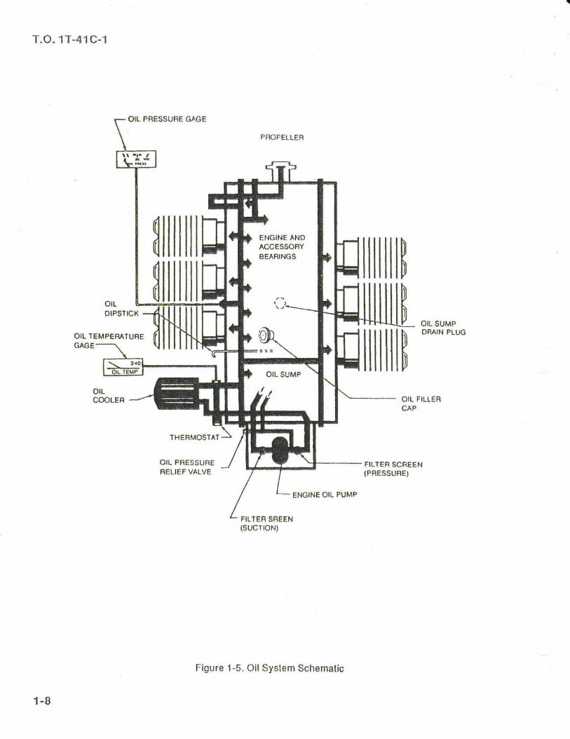
Figure 1-5. OilSystem Schematic

T.O. 1T-41C-1
FUEL IANK SUMP
OR^IN PLUG IBEFI
PLUG
FIJEL ANO AIB
THFOrILE UNII
lffil pUGL Suppt y
er-rE(C€s8 FU€L*At{ovAPoRM€CIIANICAL
-- - - lrxloE- ELCSIBCAT
-- FUEL NOZZLES
1-9
Figure 1-6. FuelSyslem Schemalic

T.O. 1T-41 C-1
NOTE
o Wilh the luel seleclor valve on BOTH, lhetotal usable fuel for all llight conditions is46 gallons, and in level llight is 51 gal-lons.
model aircraft, lhe. Juel-.sffdiff6rknob is in-!he. erigine compart-
thus preventing an excessively rich mixture dur-ing periods of low engine speed. The pump willswitch to lhe allernate flow rate at a throtile settingol approximately 2100 rpm. The up position ofthe auxiliary luel pump switch, labeled HIGH, op-erates the pump at its highest rale. The HIGHposition is used lor engine priming, for vaporpurging during hot weather operations, or lor al-ternate engine operalion if the engine-driven pumpshould malfunction. The swilch is spring-loadedto OFF lrom the HIGH posiiion and must therelorebe held in HIGH when used.
NOTE
lf the auxiliary fuel pump switch is accidenilyturned on with the master switch ON, theengine stopped, and the mixture controlknob not at FULL LEAN, the cylinder intakeports will llood and luelwill drain overboard.
The auxiliary luel pump is not used while theengine is running during normal operations. Withthe auxiliary luel pump and the engine-driven luelpump bolh functioning, an excessively rich luel-air ralio will result.
Manual Primer
A manual primer, located on the left lower switchpanel (figure 1-2), is provided to aid in slartingthe engine. lt sprays luel into the elbows ol lheengine induction manilolds lor improved starts.
Fuel Quantity lndicator
The two electrically operated fuelquantity indica-tors are located on lhe right instrument panel(f igure 1-4). The instruments indicate the fuel inthe tanks lrom empty to lull graduated in quar-ters. The indicators receive their inputs from luellevel lransmitters in each wing lank any time themaster switch is ON.
NOTE
Fuel quantity indicators are accurate onlyin stabilized straight and levetllight.
ELECTRICAL SYSTEM
Electrical energy is supplied by a 14-voll, directcurrent syslem powered by a 60-ampere, engine-driven alternator. A 12-volt bafiery, located alt of
ment and is.adidessible lhrouoh the oila*gesrd6-ir t\**":-
o On 1968 model aircralt, the fuel strainerknob is located on the inslrurnenl panelin lhe lower lelt corner.
Engine-Driven Fuel Pump
The engine-driven luel pump has an aneroid whichprovides aulomatic luel mixture for existing ambientconditions. lt provides a more desirable luel mix-lure control throughoul the operalional range,particularly at low and idle power settings.
The mixture unit is also an integral part of theengine-driven fuel pump controlling fuel llowthrough a mechanical linkage from the mixturecontrol knob.
Should the aneroid in the engine-drivenluel pump lail, it willfailto lhe FULL LEANposition and use of lhe auxiliary luelpumpon LOW accompanied by manual leaningmay be required .
Auxiliary Fuel Pump
An electric auxiliary luel pump supplies luel flowlor starting and lor engine operalion followinglailure ol the engine-driven luel pump and forvapor purging. The auxiliary {uel pump switch(figure 1-2),located on the lelt lower switch panel,is a guarded, three-position, center-ofl switch.The down position, labeled LOW, operates lhepump al one ol two possible speeds dependingon lhrottle position. With the lhroltle al a cruisesetting and the auxiliary fuel pump switch in theLOW position, suff icient luel f low is provided lorcruise llight operation with a lailed engine-drivenluel pump. When the throttle is moved towardsthe idle position, a microswitch is tripped whichcauses the auxiliary luel pump f low raie lo reduce,
ir':Y"'i"%3
1-10

T.0. 1T-41 C-1
FUEL QUANTTY DATA (U.S. GALLONS)
TANK NO.USABLE FUELALL FLIGHTCONDITIONS
ADDITIONALUSABLE FUEL
(LEVEL FLTGHT)
UNUSABLEFUEL
(LEVEL FLIcHT)
TOTAL FUELVOLUME
EACH
LEFT WING
RIGHT WING
1
1
23 gal.
23 gal.
2.5 gal.
2.5 gal.
0.5 gal.
0.5 gal.
26.0 gal.
26.0 gal.
Figure 1-7. Fuei Quantity Dala (U.S. Gallons)
lhe rear cabin bulkhead, is used to supply electri-cal power lor starting. lt also serves as an alter-nate source ol electrical power in case ol alter-nator or regulalor lailure.
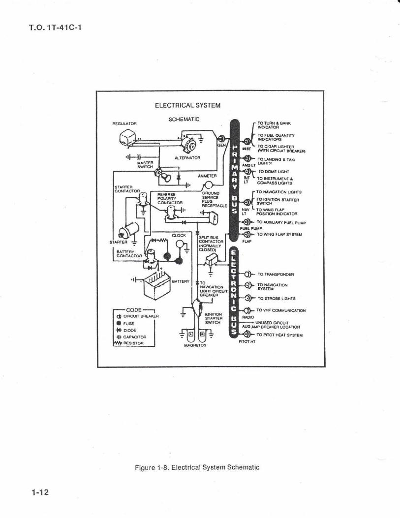
Power is supplied lo all electricalcircuits througha splil bus bar (figure 1-8). The eleclronic busconlains lhe strobe lighls, VHF radio, VOR re-ceiver, transponder, and lhe pitot heal circuits.The primary bus contains all olher electrical sys-tem circuils. With the masler switch ON, bothsides ol the bus are normally powered. However,when either an exlernal power source is con-nected, or lhe ignition switch is turned to START,a power contactor automatically deactivates lhecircuit to the electronic bus. lsolaiing the elec-lronic circuils prevents lransient vollages lromdamaging the semiconductors in the electronicequipment.
Master Switch
The master switch controls electrical power tothe aircraft electrical syslem. On 1968 model air-crall, the switch is a push-pull lype and is locatedon the lell lower switch panel (ligure 1-2). On1969 model aircrafl, the master switch is a two-piece split switch which should be used as oneswitch during normal operations.
NOTE
On 1969 model aircrafl, the split masterswitch may be benelicial during abnormalsiluations. The lelt switch serves to dis-connecl the alternator while lhe right sidedisconnects the battery.
AmmelerAll aircralt are equipped with an ammeter thatindicates lhe amount ol current llowing either toor lrom the battery. The ammeter is located be-tween the luel quantity indicators on the rightinslrument panel (ligure 1-4). Normally, the am-meler will remain within 0 to +2 needle widths ilthe alternator is operating properly and the bat-tery is in a normal state of charge. Extreme chargeor discharge rates lor any duration are indica-tions ol an electrical system mallunction.
NOTE
A weak battery or a prolonged startingperiod may cause a high ammeter reading.This is normal; however, do not take olluntilthe ammeler is within the normalrangeo[ 0 to +2 needle widths.
External Power Receptacle
A ground service plug receptacle is inslalted topermit lhe use of an exlernal power source lorcold wealher slarting. The receptacle is locatedon the lower lell side ol the engine compartment,behind an access plate. The masler swilch shouldbe ON belore connecling an external power source.
WARNING
Belore starting the engine using an exter-nal power source, be sure thal all groundpersonnel are well clear of the propellerdanger area.
1-1 1
T.O. 1T-41C-1
REGUTATOR rOruRN I EANKTNOTCA'OR
IO FU€L Q{JAXTIWINDICATORS
IO C|GAR UGHTERiltr iiurli?iiciii'ift,qxrnAIEFINATOfi TO LAt{ONG e TAx
^r[a, uoxrs
IO DOtlE LIGHI
IO I}ISTRUM€NI Icof,iP^sg LtGHls
lo lr^vtc rloN LTGHIS
lo rcltmoN srAFrERSWrclr10 wlNG FI.APPOStnOil ftDTCATOR
IO AUXILIAFY FUEL PUMP
TO WilIG FI.AP SYSI€M
TO IRANSPONOEF
TONAVtGAItONuoHT ctncLnrBRE X€F
TO NAVIGATIONSYSTEM
COOE
-t
lo sTFroSE Lr6Ht3
ro vHF colrMuNtc^Tlolt
o ctRcun SREAKEF| rGNlTroltSTARTEFIswTo{O rusr
{* o,ooe
{} cePectroR
UNUS€D clRCU|rAUO AMP BR€AX€R rocAnoN
TO P|IOT HEAI SYST€M
RESISTOR
FEiE;G--GRoUNOijouiifrY SEFVICEconracroR PLUO
1-12
Figure 1 -8. Electrical System Schemalic
Use ol other lhan a 12-volt power sourcemay damage eleclrical systems. Theground service plug receplacle circuit in-corporales polarity protection. Power lromlhe external source will llow only if theservice plug is connected lo lhe aircraltproperly.
Circuit Breakers and Fuses
The majority ol electrical circuils in the aircralt areprotected by "push lo resel" circuil breakers locatedon the lell lower switch panel (ligure 1-2). Excep-tions are lhe external power circuit and the clockcircuit which are prolecled by luses located nearthe battery.
lf a circuit breaker pops oul, it may beresel once il no other eleclrical mallunc-lions exist. ll the circuit breaker pops outalter being reset, do not attempt lo resetit again. Terminale the mission and landas soon as conditions permit.
NOSEWHEEL STEERING SYSTEM
Nosewheel steering is accomplished through useol the rudder pedals. The nosewheel is sleerableup to approximately 10 degrees each side ol neu-lral, aller which it becomes lree wheeling to amaximum delleclion ol 30 degrees right or lelt olcenter when dilf erential braking is used. A shimmydamper is provided to minimize nosewheelshimmy.
BRAKE SYSTEM
The hydraulic disc brakes on the main wheelsare individually operaled by applying toe pres-sure to the upper portion of either set ol rudderpedals. Depressing the pedals activates the brakecylinders, resulting in a braking aclion on lhemain landing gear wheels. A masler cylinder at-tached to each of lhe lelt seal (pilot) pedalstransmits hydraulic pressure to the respective mainwheel brake cylinder, thus applying brakes. Theright seat brake pedals are connected by me-
T.O. 1T-41C-1
chanical linkage to lhe pilot's brake pedals, andpressure applied to the right seat pedals is trans-mitted mechanically to lhe masler cylinders.
ll a sharper lurn is desired than can bemade with the rudder pedal steeringmechanism, use lhe brakes to establishthe rate of lurn desired. While making aturn in this manner, keep lhe inside wheelrolling. Any attempt to pivot lhe aircrallon a locked inside wheel may damage lhewheel, lire or strut. This ii particularlydangerous because the damage may nolbe apparenl. To make sure that the insidewheel rolls, release the inside brake inter-mittently. Apply the brakes smoothly,evenly, and cautiously at all limes.
Parking Brake
The parking brake handle is located beneath theleft lower switch panel (ligure 1-2) and is used loset the brakes. The handle-and-rachet mecha-nism is connected by a cable to linkage at themaster cylinders. Pulling out lhe handle depressesbolh master cylinder piston rods and the rachellocks lhe handle in this position until lhe handteis.lurned and released. To set the brakes, pullthe parking handle out and turn il to the 6 o'clockposition. To release the parking brake, rotate thehandle 90 degrees clockwise to the 9 o'clockposition and let it return to the original retractedposition.
WING FLAP SYSTEM
The wing llaps are electrically operafed and arecontrolled by a three-position switch on the rightlower switch panel (figure 1-3). This swilch, spring-loaded to the olf position, controls an eleclricmotor that raises or lowers the llaps by means ofcables and push-pull rods. The motor is protectedlrom shorts and overheal by a circuit breakerlocated on the circuit breaker panel. The electri-cally-operated llap posilion indicator is calibratedin degrees ol llap extension lrom 0 to 40 de-grees.
1-13

T.O. 1T-41 C-1
Holding lhe wing llap switch in the lull upor down posilion lor extended periods maycause the llap molor lo overheat and thecircuit breaker to pop.
FLIGHT CONTHOL SYSTEM
The aileron, elevator, and rudder control syslemsare comprised ol push-pull rods, bellcranks, cables,and pulleys. The aileron and elevalor systemsare connected lo the conlrol wheel. The ruddersystem is connected to the rudder pedals.
Properly adjusted conlrols, when operaled, movein the correct direction, are lree ol binding, anddo not require excessive lorce for application.
Excessive lorce or abrupt control inputsmay cause control system damage.
Trim System
A trim lab is provided on the trailing edge ol theright elevator to reduce control wheel lorces andlo allow hands-olf llight at normal airspeeds. Anelevator trim wheel, mounled in the cenler ped-estal (ligure 1-4), provides manual adjustment ofthe trim lab. The trim wheel and the adjacentpointer are labeled trom top lo botlom, NOSEDOWN, TAKEOFF, and NOSE UP. The pointerindicates the elevator lrim position. Forward rotationol the wheel provides nose-down trim. Aft rotationprovides a nose-up setting. Positioning the pointerabeam lhe white marker at the TAKEOFF labelprovides the normal takeolf trim setting.
Control Lock/Gust Locks
When lhe aircrall is on lhe ground unattended, aconlrol lock is used lo lock the elevalor and aileronconlrol syslems to prevent damage lrom windgusts. The lock is designed to engage a hole inthe pilot's conlrolwheel shalt and instrument panelmounted bracket. A llag on the end ol the controllock covers lhe ignition switch to warn againststarting lhe engine with the lock installed. Therudder is protected lrom minor bulleting by thelinkage between lhe nosewheel and rudder syslem.
Exlernal gust locks are also provided lor allllightcontrol surlaces lor use when slrong winds areexpecled.
Crew members should be sure the controlwheel is properly positioned prior to in-slalling lhe conlrol lock. On 1969 modelaircralt, the controllock should be removedprior to installing the gust lock on the el-evator.
STALL WARNING HORN
The stall warning horn is a pneumatic device,aulomatically activated by diflerential air pres-sure. The system includes an opening in the leadingedge ol the lelt wing, lor sensing pressure, and areed type horn located in lhe upper lett side ofthe cabin. As the wing approaches a stall, airllowover lhe wing creates a low pressure condition inthe area ol the wing opening. This condition causesair to be drawn lrom the cockpit through the horn,resulling in an audible warning at airspeeds 5 lo10 mph above the stall in all contigurations.
INSTBUMENTS
The lollowing paragraphs cover only those in-strumenls which are not part of a complete sys-tem such as the luel system, engine, etc. Thellighl instruments consists ol an airspeed indica-lor, vertical velocity indicalor, altimeter, turn-and-slip indicator, attitude indicator, heading indicator,magnetic compass, and clock. All llight instru-ments are located in the left instrumenl paneldirectly in fronl ol the pilot (ligure 1-4), exceptthe magnetic compass which is located on thetop ol the dash panel.
Pitot-Static System and lnstrumentsThe pitot-static system suppties air pressure tooperate the airspeed indicalor. The static portionof lhe system supplies the operating pressureslor the vertical velocity indicator, allimeler, andairspeed indicator. The pitot-static system iscomposed of an electrically heated pitot tubemounted under the lelt wing, two exlernal staticporls, located on either side ol lhe aircralt luse-lage, and lhe associaled plumbing necessary toconnecl the inslruments to their sources.
1-14