today and into the future - general cable...testing per ieee 323 and ieee 383 • provides excellent...
TRANSCRIPT

CABLE SOLUTIONSto meet the application needs of nuclear power plants
TODAY AND INTO THE FUTURE

Telephone: (800) 237-6419 x8726International: [email protected]
I
GENERAL C ABLE DEL IVERS Advanced Reliability, Safety And Sustainability To The Nuclear Power Industry
Safe, Reliable Cable Solutions for Safe, Reliable Operation
With nearly 40 years of nuclear experience and continuous service, General Cable is dedicated to advancing nuclear power and its commitment to providing safe and reliable electricity. We continue to invest in research and development to maintain and extend our leadership in technology, manufacturing and quality assurance—delivering nuclear-qualified cables with the design, performance and reliability to meet the needs of nuclear power plants both today and into the future.
At General Cable, continuous improvement as it relates to safety and best practices, both within our organization and in every nuclear cable we design and manufacture, is part of our corporate culture—it’s who we are. Our people are the powerful drivers behind our success as a nuclear wire and cable supplier and what differentiates us in the industry’s eyes in terms of quality, service and performance. These are the talented and dedicated individuals with expert knowledge of what it takes to deliver technology-driven high-performance products for nuclear power plants to ensure long-standing, sound and reliable operation under any condition.
Delivering value through leadership, innovation and technology, General Cable provides its nuclear customers with: • Anearly40-yeartrackrecordofprovidingnuclearcablewithproven
quality and long-term reliability• Performancethatmeets/exceedsstringentstandardsandevolving
safety expectations• Optimizedcabledesignstoensuremorethan60yearsoftrustworthy
power plant operation • Ongoinginvestmentandacommitmenttocontinuedimprovementin
all areas of our company• Astrongproponentforenergyindependence,alternativeenergy
sources and sustainability• Dedicatedserviceandsupportwiththeflexibilityandresponsiveness
to deliver valuable results
As one of the most established wire and cable companies in the world, General Cable has been leading the way in energy generation, transmission and distribution solutions for more than 165 years. We offer our valued nuclear customers the presence and strength of a large company, with the agility and responsiveness of a small one.
With more than 14,000 associates operating on six continents, General Cable serves its customers through a global network of 57 manufacturing facilities in26countries,withsales representatives and distribution centers worldwide. The combination of breadth of product line, strong brand recognition, and dedicated distribution and customer service makes General Cable your energy partner for the regeneration of nuclear power worldwide.
All information in this catalog is presented solely as a guide to product selection and is believed to be reliable. All printing errors are subject to correction in subsequent releases of this catalog. Although General Cable has taken precautions to ensure the accuracy of the product specifications at the time of publication, the specifications of all products contained herein are subject to change without notice.

Telephone: (800) 237-6419 x8726International: [email protected]
II
Zero and Beyond – Because NOTHING Else is Acceptable
At General Cable, our environmental, health and safety philosophy extends well beyond zero accidents in the workplace—it is in our DNA.RecognizedasoneofAmerica’ssafestcompanies*in2012with an industry-leading safety record, General Cable strongly encourages all of its associates to take responsibility for their decisions and actions, and to be role models of safety excellenceto co-workers, families and communities.
While General Cable’s Zero and Beyond philosophy engages our associates at every level to think and act safely across all aspects of our business, we also embrace the unique safety requirements of the nuclear industry. With safety at the very core of our manufacturing excellence, all of our nuclear cables are designed to provide an infrastructure for safe and reliable nuclear operation.
General Cable’s corporate culture of safety provides:• Absoluteunderstandingthatnuclearsolutionsmustsurpassthehighestlevelsofsafetyandreliability• OHSAS18001orequivalenthealthandsafetymanagementsystemsinallfacilities• Comprehensivetesting,designcontrolandqualityassurancetoensureoptimizedcablesafety• DemonstratedsafetyleadershipacrossallmanufacturingfacilitieswithdedicatedEHSofficers• Significantinvestmentininfrastructurewithafocusonsafetyfirstthroughconsequencethinking• Ongoingcommitmenttocontinuallymeasureandimprovesafetythroughresponsiblediscovery• Significantlylowerreportedaccidentandillnessratesthantheindustryaverage
General Cable has one worldwide safety vision and goal – ZERO AND BEYOND. Through a corporate-wide practice of working safer by working together, General Cable extends that vision and goal into every nuclear cable we design and manufacture.
Responsible Operations Deliver Sustainable Solutions
General Cable recognizes our role and responsibility in promoting sustainability through continuous improvement in all areas of our company. As a result, our global facilities have fully implemented ISO14001orequivalentenvironmentalmanagementsystems.
The quest to introduce new and better products through ongoing advancementsinenvironmentaldesignsreflectsourcommitmentto achieving and exceeding industry standards and proactively responding to global environmental issues, while helping our nuclear customers deliver clean and reliable electricity. Just as important as internal sustainable practices is our inherent ability todesignenergy-efficientcablesthataredurable,reliableandoptimized for long-standing, sustainable nuclear power plant operation.
General Cable was the first cable manufacturer to obtain certification for its environmental management system, in accordance with the ISO 14001 and EMAS Standards.
* EHS Magazine, November, 2012.

Telephone: (800) 237-6419 x8726International: [email protected]
III
GENERAL C ABLE DEL IVERS Innovation for Next Generation Nuclear Power
A History of Technological Advancements
For more than four decades, General Cable has consistently delivered technologically advanced cables that have enabled nuclear power to remain a safe, affordable and reliable source of clean energy. With a proven track record that stems from an intimate involvement and strong position in the electric utility market, General Cable is committed to partnering with our nuclear customers to share expert knowledge, identify evolving needs and solve today’s tough nuclear application challenges, both inside containment and out.
General Cable is strongly positioned to lead the nuclear industry well into the21stcenturyandbeyond.ThroughongoinginvestmentinR&D,world-renowned testing, unsurpassed in-house compounding capabilities and a dedicated nuclear team, General Cable has developed the latest materials and advanced cable formulations with proven performance to help our nuclear customers differentiate themselves with safe, reliable and optimized nuclearpowerplantoperationsforthenext60yearsandbeyond.
ULTROL® 60+—safe, reliable, advanced cable solutions for thenext60years and beyond.
Telephone: (800) 237-6419 x8726International: [email protected]
IV
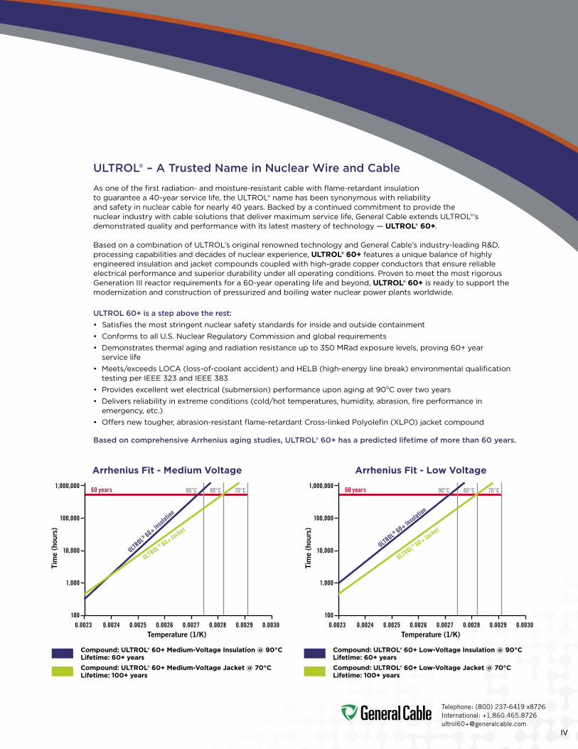
ULTROL® – A Trusted Name in Nuclear Wire and Cable
Asoneofthefirstradiation-andmoisture-resistantcablewithflame-retardantinsulationtoguaranteea40-yearservicelife,theULTROL®namehasbeensynonymouswithreliabilityand safety in nuclear cable for nearly 40 years. Backed by a continued commitment to provide the nuclearindustrywithcablesolutionsthatdelivermaximumservicelife,GeneralCableextendsULTROL®’sdemonstrated quality and performance with its latest mastery of technology — ULTROL® 60+.
BasedonacombinationofULTROL’soriginalrenownedtechnologyandGeneralCable’sindustry-leadingR&D,processing capabilities and decades of nuclear experience, ULTROL® 60+ features a unique balance of highly engineered insulation and jacket compounds coupled with high-grade copper conductors that ensure reliable electricalperformanceandsuperiordurabilityunderalloperatingconditions.ProventomeetthemostrigorousGenerationIIIreactorrequirementsfora60-yearoperatinglifeandbeyond,ULTROL® 60+ is ready to support the modernization and construction of pressurized and boiling water nuclear power plants worldwide.
ULTROL 60+ is a step above the rest:• Satisfiesthemoststringentnuclearsafetystandardsforinsideandoutsidecontainment• ConformstoallU.S.NuclearRegulatoryCommissionandglobalrequirements• Demonstratesthermalagingandradiationresistanceupto350MRadexposurelevels,proving60+year
service life• Meets/exceedsLOCA(loss-of-coolantaccident)andHELB(high-energylinebreak)environmentalqualificationtestingperIEEE323andIEEE383
• Providesexcellentwetelectrical(submersion)performanceuponagingat90⁰Covertwoyears• Deliversreliabilityinextremeconditions(cold/hottemperatures,humidity,abrasion,fireperformanceinemergency,etc.)
• Offersnewtougher,abrasion-resistantflame-retardantCross-linkedPolyolefin(XLPO)jacketcompound
Based on comprehensive Arrhenius aging studies, ULTROL® 60+ has a predicted lifetime of more than 60 years.
Compound: ULTROL® 60+ Medium-Voltage Insulation @ 90°C Lifetime: 60+ yearsCompound: ULTROL® 60+ Medium-Voltage Jacket @ 70°C Lifetime: 100+ years
Compound: ULTROL® 60+ Low-Voltage Insulation @ 90°C Lifetime: 60+ yearsCompound: ULTROL® 60+ Low-Voltage Jacket @ 70°C Lifetime: 100+ years
1,000,000
100,000
10,000
1,000
100
60 years
ULTROL® 60+ In
sulation
ULTROL® 60+ Jacket
90°C 80°C 70°C 90°C 80°C 70°C
0.0023 0.0024 0.0025 0.0026 0.0027 0.0028 0.0029 0.0030Temperature (1/K)
Tim
e (h
ours
)
1,000,000
100,000
10,000
1,000
100
60 years
ULTROL® 60+ Insulatio
n
ULTROL® 60+ Jacket
0.0023 0.0024 0.0025 0.0026 0.0027 0.0028 0.0029 0.0030Temperature (1/K)
Tim
e (h
ours
)
Arrhenius Fit - Medium Voltage Arrhenius Fit - Low Voltage

Telephone: (800) 237-6419 x8726International: [email protected]
V
100% Quality Assurance Guaranteed
For more than a century, General Cable has been 100 percent committed to ongoing improvement and quality assurance across all aspects of our business. We continually strive to develop, produce and deliver products that meet our customers’ highest standards for performance, quality, value, service life and safety.
UnderASMENQA-1,10CFR50AppendixBandCSAZ299.1qualityassuranceprogramsthatincludeahighlyexperienced nuclear quality team, General Cable ensures every reel of ULTROL® 60+ leaving the plant meets stringentindustrystandardsandthespecifiedneedsofourcustomers.EveryULTROL® 60+ cable is followed throughtheentiremanufacturingprocess—fromrawmaterialinspectiontorigorousperformancetesting.Everyreel includes inspection results and certified documentation that is maintained and traceable.
General Cable’s quality assurance system for design, manufacturing and testing includes:• ASMENQA-1:1994andNQA-1:2008with2009supplemental• ISO9001:2008Certified (UL/DQSregistered)
• ANSIN45.2• NUREG0800Section17.5• NuclearRegulatoryCommissionUSNRC10CFR50AppendixB,10CFR21compliant
• CSAZ299.1:1985• CSACategoryProgramforTesting (2ndpartyapprovaltoISO17025)
• ULDataAcceptanceProgram (2ndpartyapprovaltoISO17025)
• NUPICandNIAC–AuditedQualitySystem
Lifelong Manufacturing Excellence
HavingproducedULTROL®since1970,GeneralCable’sWillimantic,Connecticutfacilityisfoundedonalegacyof having the vision, innovation and cable expertise to lead markets that require specialized cable solutions. Today,WillimanticisanISO9001-certifiedmanufacturingplantwithdedicatedassociateswhoprovidethetechnical expertise, and quality manufacturing and testing capabilities to maintain its nuclear status—all assured throughregularNQA-1andAppendixBauditsbytheNuclearProcurementIssuesCommittee(NUPIC),NuclearIndustryAssessmentCommittee(NIAC)andotherqualityassuranceorganizations.
Dedicatedtomanufacturingexcellence,theASMENQA-1Tier-1Willimanticfacilityfeaturessomeofthemostadvanced technology of its kind, offering unmatched reliability and production processes. The Willimantic facility is supported by Appendix B Tier-2 manufacturing capabilities, extensive testing and advanced material development at General Cable’s state-of-the-art technology centers.
Extensive third-party testing, performed by an Appendix B supplier, ensures the conformance of ULTROL® 60+ to all nuclear requirements.
GENERAL C ABLE DEL IVERS Quality Assurance, Manufacturing Excellence and Unwavering Dedication

Telephone: (800) 237-6419 x8726International: [email protected]
VI
A Dedicated Nuclear Team
To address the special needs of the nuclear market, match current and future nuclear application needs, and remain a valuable resource with an uninterrupted record of supply, General Cable backs ULTROL® 60+ with a cross-functional nuclear team built on long-standing industry experience, technical know-how and a mindset of continuous improvement.
General Cable’s nuclear team is committed to identifying objectives, establishing goals, defining action plans and drawing upon General Cable resources. Through active participation with standards bodies and long-term relationships with industry leaders, power plant operators, contractors and reactor manufacturers, our experienced team is empowered to satisfy and support a complex nuclear business—all with a commitment to safety and reliability.
Our experienced team is empowered to satisfy and support a complex nuclear business—all with a commitment to safety and reliability.

Telephone: (800) 237-6419 x8726International: [email protected]
VII
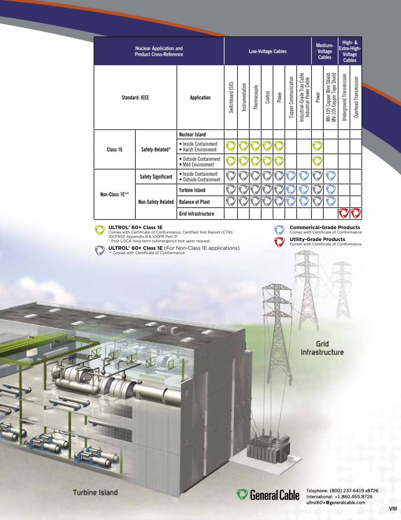
GENERAL C ABLE DEL IVERS Cable Solutions to meet the Application Needs of the Nuclear Power PlantThe ULTROL® 60+ product line provides a full line of nuclear generating station cables for both inside and outside containment—allqualifiedfora60-yearservicelife.ULTROL® 60+ cables meet the application needs of the nuclear powerindustry,deliveringreliablelow-andmedium-voltagepowertoensureefficientpowerproductionaswellasdistribution and control, while transmitting the information needed for plant safety, critical monitoring and accurate measurement.
From the nuclear island, turbine island and balance of the plant to the grid infrastructure, ULTROL® 60+ delivers optimized reliable operation, maintenance and management in all known reactor environments.
• Exceeds60-yearserviceliferequirementsforinsulations,shieldsandjackets• MeetsrequirementsofIEEE323andIEEE383• MeetstherequiredflametestingofIEEE1202andIEEE383• Offerslong-termthermalenduranceatelevatedand
low temperatures• Meetscurrentpressurizedandboilingwaternuclearpowerplant requirementsforservicelifebeyond60years
Telephone: (800) 237-6419 x8726International: [email protected]
VII
Telephone: (800) 237-6419 x8726International: [email protected]
VIIIVIII
Telephone: (800) 237-6419 x8726International: [email protected]
Nuclear Application and Product Cross-Reference Low-Voltage Cables
Medium-VoltageCables
High- &Extra-High-
VoltageCables
Standard: IEEE Application
Switc
hboa
rd (S
IS)
Inst
rum
enta
tion
Ther
moc
oupl
e
Cont
rol
Powe
r
Copp
er C
omm
unica
tion
Indu
stria
l-Gra
de Tr
ay C
able
Indu
stria
l Pow
er C
able
Powe
r
MV-1
05 C
oppe
r Wire
Shi
eldMV
-105
Cop
per T
ape S
hield
Unde
rgro
und
Tran
smiss
ion
Over
head
Tran
smiss
ion
Class 1E Safety-Related*
Nuclear Island
• Inside Containment• Harsh Environment
• Outside Containment• Mild Environment
Non-Class 1E**
Safety Significant • Inside Containment• Outside Containment
Non-Safety Related
Turbine Island
Balance of Plant
Grid Infrastructure
ULTROL® 60+ Class 1E ComeswithCertificateofConformance;CertifiedTestReport(CTR):10CFR50AppendixB&10CFRPart21 *Post-LOCAlong-termsubmergencetestuponrequest
ULTROL® 60+ Class 1E(ForNon-Class1Eapplications) **ComeswithCertificateofConformance
Commerical-Grade Products Comes with Certificate of Conformance
Utility-Grade Products Comes with Certificate of Conformance

Telephone: (800) 237-6419 x8726International: [email protected]
ADVANCING NUCLEAR POWERULTROL® 60+ Cable Selection Guide
SPEC DESCRIPTION VOLTAGE INSULATION/JACKET CONDUCTOR SIZE/STRAND IMAGE
ULTROL® 60+ CLASS 1E /SAFETY-RELATED LOW-VOLTAGE SIS SWITCHBOARD WIRE - TYPE SIS & TYPE SIS/XHHW-2
100-60 SingleConductor 600V FR-XLPE 18AWG(0.82mm2)-1000kcmil(507mm2)ClassB
125-60 SingleConductor 600V FR-XLPE 18AWG(0.82mm2)-1000kcmil(507mm2)ClassK&H
ULTROL® 60+ CLASS 1E/SAFETY-RELATED LOW-VOLTAGE POWER CABLE - TYPE RHH/RHW-2
150-60 SingleConductor HeavyWall 600V FR-XLPE 14AWG(2.08mm2)-1000kcmil
(507mm2)ClassB
175-60 SingleConductor DualWall 600V FR-XLPE/XLPO 14AWG(2.08mm2)-1000kcmil
(507mm2)ClassB
ULTROL® 60+ CLASS 1E/SAFETY-RELATED LOW-VOLTAGE THERMOCOUPLE EXTENSION CABLE
185-601-12Pairs
IndividuallyShieldedOverallShield
600V FR-XLPE/XLPO 18AWG(0.82mm2)and16AWG(1.31mm2)solidalloy
ULTROL® 60+ CLASS 1E/SAFETY-RELATED LOW-VOLTAGE INSTRUMENTATION CABLE
200-60 2-37 Multi-conductor 600V FR-XLPE/XLPO 18AWG(0.82mm2)and16AWG
(1.31mm2)ClassB
225-602-37
Multi-conductorOverallShield
600V FR-XLPE/XLPO 18AWG(0.82mm2)and16AWG(1.31mm2)ClassB
250-602-19
Pairs/Triads IndividuallyShielded
OverallShield
600V FR-XLPE/XLPO 18AWG(0.82mm2)and16AWG(1.31mm2)ClassB
ULTROL® 60+ CLASS 1E/SAFETY-RELATED LOW-VOLTAGE CONTROL CABLE - TYPE TC-ER*
275-60 2-37 Multi-conductor 600V FR-XLPE/XLPO 14AWG(2.08mm2)-10AWG
(5.26mm2)ClassB
300-602-37
Multi-conductorOverallShield
600V FR-XLPE/XLPO 14AWG(2.08mm2)-10AWG(5.26mm2)ClassB
*-ERfor>2conductors
ULTROL® 60+ CLASS 1E/SAFETY-RELATED LOW-VOLTAGE POWER CABLE - TYPE TC-ER
325-60 3or4Conductor with Ground 600V FR-XLPE/XLPO 8AWG(8.36mm2)-750kcmil
(380mm2)ClassB
ULTROL® 60+ CLASS 1E/SAFETY-RELATED MEDIUM-VOLTAGE POWER CABLE - TYPE MV-105
340-60 SingleConductor Shielded
5kV(133%)&8kV(100%) EPR/XLPO 6AWG(13.3mm2)-1000kcmil
(507mm2)ClassB
15kV(133%) EPR/XLPO 2AWG(33.6mm2)-1000kcmil
(507mm2)ClassB
IX

Telephone: (800) 237-6419 x8726International: [email protected]
1
ADVANCING NUCLEAR POWERTABLE Of CONTENTS
ICON KEy
class
1EraTed class 1e
FlaMe-reTardaNT
MoIsTure-resIsTaNT
uV/suNlIGHT-resIsTaNT
oIl-resIsTaNT
-25˚C
cold beNd
cold beNd
-40˚C
HeaVy wall
cross-lINked
cuT-THrouGH
SECTION 1 ULTROL® 60+ CABLES 3-27
SpEC. NO. pRODUCT DESCRIpTION REv. DATE pAGE NO.
SPEC100-60 ULTROL®60+Class1ESISSwitchboardWire,ClassB May2013 4-5
SPEC125-60 ULTROL®60+Class1ESISSwitchboardWire,ClassK&H May2013 6-7
SPEC150-60 ULTROL®60+Class1EPowerCableHeavyWall,SingleConductor
May2013 8-9
SPEC175-60 ULTROL®60+Class1EPowerCableDualWall,SingleConductor
May2013 10-11
SPEC185-60 ULTROL®60+Class1EThermocoupleExtensionCableIndividuallyShieldedPairs,OverallShield
May2013 12-13
SPEC200-60 ULTROL®60+Class1EInstrumentationCableMulti-Conductor
May2013 14-15
SPEC225-60 ULTROL®60+Class1EInstrumentationCableMulti-Conductor,OverallShield
May2013 16-17
SPEC250-60 ULTROL®60+Class1EInstrumentationCableIndividuallyShieldedPairsorTriads,OverallShield
May2013 18-19
SPEC275-60 ULTROL®60+Class1EControlCableMulti-Conductor
May2013 20-21
SPEC300-60 ULTROL®60+Class1EControlCableMulti-Conductor,OverallShield
May2013 22-23
SPEC325-60 ULTROL®60+Class1EPowerCable3or4ConductorswithGround
May2013 24-25
SPEC340-60 ULTROL®60+Class1EMedium-VoltagePowerShielded,SingleConductor
May2013 26-27
SECTION 2 TEChNICAL INfORMATION 29-50
SpEC. NO. pRODUCT DESCRIpTION REv. DATE pAGE NO.
SPECA100 CommonColorSequence May2013 30
SPECA125 Temperature Conversion Table Oct. 2011 31
SPECA150 MetricConversionFactors Sept.2010 32
SPECA185 AWG(AmericanWireGauge)tomm2
(MillimetersSquared)ConversionMay2013 33
SPECB025 Class B Conductors for General Wiring Mar.2012 34
SPECB030 Class C Conductors for General Wiring Feb. 2011 35
SPECB035 ClassHConductorsforGeneralWiring Feb. 2011 36
SPECB040 Class I Conductors for General Wiring Mar.2012 37
SPECB045 ClassKConductorsforGeneralWiring Mar.2012 38
SPECD005 RecommendedReelHandlingPractices May2013 39
SPECD025 RecommendedCableHandlingPractices Oct. 2011 40
SPECD050 RecommendedCableStoragePractices May2013 41
SPECE005 Pre-InstallationInstructions Apr. 2010 42
SPECE025 Installation - Overview and Checklist Jan. 2011 43
SPECE050 Installation-Feed-InSetups Apr. 2010 44-45
SPECE075 Installation-ConductorMaximumPullingTensions Oct. 2012 46-47
SPECE100 Installation - Training and Bending Limitations Apr. 2010 48
SPECE130 Installation-MaximumSidewallPressure May2013 49
INDEX CatalogNumberIndex May2013 50
INcreased FlexIbIlITy
radIaTIoN-resIsTaNT

2
ADVANCING NUCLEAR POWERNOTES

Telephone: (800) 237-6419 x8726International: [email protected]
3
ADVANCING NUCLEAR POWERTABLE Of CONTENTS
SECTION 1 ULTROL® 60+ CABLES 3-27
SpEC. NO. pRODUCT DESCRIpTION REv. DATE pAGE NO.
SPEC100-60 ULTROL®60+Class1ESISSwitchboardWire,ClassB May2013 4-5
SPEC125-60 ULTROL®60+Class1ESISSwitchboardWire,ClassK&H May2013 6-7
SPEC150-60 ULTROL®60+Class1EPowerCableHeavyWall,SingleConductor
May2013 8-9
SPEC175-60 ULTROL®60+Class1EPowerCableDualWall,SingleConductor
May2013 10-11
SPEC185-60 ULTROL®60+Class1EThermocoupleExtensionCableIndividuallyShieldedPairs,OverallShield
May2013 12-13
SPEC200-60 ULTROL®60+Class1EInstrumentationCableMulti-Conductor
May2013 14-15
SPEC225-60 ULTROL®60+Class1EInstrumentationCableMulti-Conductor,OverallShield
May2013 16-17
SPEC250-60 ULTROL®60+Class1EInstrumentationCableIndividuallyShieldedPairsorTriads,OverallShield
May2013 18-19
SPEC275-60 ULTROL®60+Class1EControlCableMulti-Conductor
May2013 20-21
SPEC300-60 ULTROL®60+Class1EControlCableMulti-Conductor,OverallShield
May2013 22-23
SPEC325-60 ULTROL®60+Class1EPowerCable3or4ConductorswithGround
May2013 24-25
SPEC340-60 ULTROL®60+Class1EMedium-VoltagePowerShielded,SingleConductor
May2013 26-27
ICON KEy
class
1EraTed class 1e
FlaMe-reTardaNT
MoIsTure-resIsTaNT
uV/suNlIGHT-resIsTaNT
oIl-resIsTaNT
-25˚C
cold beNd
cold beNd
-40˚C
HeaVy wall
cross-lINked
cuT-THrouGH
INcreased FlexIbIlITy
radIaTIoN-resIsTaNT

Telephone: (800) 237-6419 x8726International: [email protected]
4
ADVANCING NUCLEAR POWER
radIaTIoN-resIsTaNT
class
1EraTed
class 1eFlaMe-
reTardaNTMoIsTure-resIsTaNT
uV/suNlIGHT-resIsTaNT
cross-lINked
ULTROL® 60+ SIS Switchboard WireClass BClass 1E Nuclear600 v, 90°C, vW-1, UL Type SIS and Type SIS/XHHW-2
SpEC 100-60May, 2013
1. Conductor: • 18AWGthru1000kcmiltinnedannealed
copperperASTMB33;ClassBstrandingperASTMB8
2. Insulation: • Flame-retardant,heat-,moisture-,sunlight-
andradiation-resistant,thermosetULTROL®60+Cross-linkedPolyethylene(FR-XLPE)
• Colorcode:Gray
print:• For18AWG&16AWG:
GENERALCABLE(WC)ULTROL®60+1/CXXAWGCOPPERFR-XLPE(UL)TYPESIS600V90̊ CVW-1NUCLEARDAYMONTHYEAR
• For14AWGthru4/0AWG: GENERALCABLE(WC)ULTROL®60+1/CXXAWGCOPPERFR-XLPE(UL)TYPESIS/XHHW-2600V90̊ CVW-1NUCLEARDAYMONTHYEAR
Note:Sizes1/0AWG&largerinclude:TRACEABILITYNUMBER&SEQUENTIALFOOTAGEMARK
• For250kcmilthru1000kcmil: GENERALCABLE(WC)ULTROL®60+1/CXXXKCMILCOPPERFR-XLPE(UL)TYPEXHHW-2600V90̊ CVW-1NUCLEARDAYMONTHYEARTRACEABILITYNUMBERSEQUENTIALFOOTAGEMARK
Options:• Conductorstranding• ISOMetricconductor• Coloredinsulation
Applications:• ULTROL®60+SISisa600Vsingleinsulated
conductor,thermoset,Class1Eratedswitchboard wire
• ForuseinClass1Elow-voltageapplicationsin operation and interconnection of protective devices where optimum performance is required and where flameretardancyiscritical
Features:• Ratedat90̊ Cwetordry• Fullytraceable• Qualifiedfor60-yearservicelife• Gammaandbetaradiationresistant
(upto350megarads)• Submergenceoperability• Long-termthermalenduranceandsuperior
electricals • Excellentmechanicalcut-throughproperties• Long-termmoistureandradiationstability• Freestrippingforeaseoftermination• Meetscoldbendtestat-40°C
Industry Compliances:• Class1EQualifiedinaccordancewithIEEE
323-1974/2003andIEEE383-1974/2003• ICEAS-95-658• UL44SIS/XHHW-2
Flame Test Compliances:• IEEE383:1974• IEEE383:2003• ICEAT-29-520• IEEE1202/FT4-1991,Aged&Unaged• VW-1
Other:• Qualityassuranceprograminaccordance
withNRC10CFR50AppendixB• ANSIN45.2• ASMENQA-1• NIAC• NUPIC
packaging:• Materialtobeshippedonnon-returnable
wooden reels
Product Construction
cold beNd
-40˚C
cuT-THrouGH
2
1

Telephone: (800) 237-6419 x8726International: [email protected]
5
ADVANCING NUCLEAR POWER
CATALOGNUMBER
COND. SIZE (AWG/kcmil)
COND. STRAND
MINIMUM AVG.INSULATIONTHICKNESS
NOMINAL CABLEO.D. COPPER WEIGHT NET WEIGHT
INCHES mm INCHES mmLBS/
1000 FT kg/kmLBS/
1000 FT kg/km
10060.18.1 18 7/.0152 0.030 0.76 0.108 2.69 5 8 10 15
10060.16.1 16 7/.0192 0.030 0.76 0.118 2.95 8 12 14 21
10060.14.1 14 7/.0242 0.030 0.76 0.133 3.33 13 19 20 30
10060.12.1 12 7/.0305 0.030 0.76 0.152 3.81 20 30 28 42
10060.10.1 10 7/.0385 0.030 0.76 0.175 4.39 32 48 42 63
10060.8.1 8 7/.0486 0.045 1.14 0.236 5.92 51 76 71 105
10060.6.1 6 7/.0612 0.045 1.14 0.273 6.86 81 121 104 155
10060.4.1 4 7/.0772 0.045 1.14 0.320 8.05 129 192 158 235
10060.2.1 2 7/.0974 0.045 1.14 0.379 9.55 205 305 242 361
10060.1.1 1 19/.0664 0.055 1.40 0.437 11.0 258 384 305 453
10060.1/0.1 1/0 19/.0745 0.055 1.40 0.476 12.0 326 485 378 563
10060.2/0.1 2/0 19/.0837 0.055 1.40 0.521 13.2 411 612 470 700
10060.3/0.1 3/0 19/.0940 0.055 1.40 0.571 14.4 518 771 584 870
10060.4/0.1 4/0 19/.1055 0.055 1.40 0.627 15.9 653 972 728 1083
10060.250.1 250 37/.0822 0.065 1.65 0.695 17.6 772 1149 865 1287
10060.350.1 350 37/.0973 0.065 1.65 0.798 20.2 1081 1609 1192 1773
10060.500.1 500 37/.1162 0.065 1.65 0.927 23.4 1544 2297 1678 2497
10060.750.1 750 61/.1109 0.080 2.03 1.137 28.8 2316 3446 2507 3731
10060.1000.1 1000 61/.1280 0.080 2.03 1.287 32.6 3088 4595 3311 4926
Dimensions and weights are nominal; subject to industry tolerances.
ULTROL® 60+ SIS Switchboard WireClass BClass 1E Nuclear600 v, 90°C, vW-1, UL Type SIS and Type SIS/XHHW-2
SpEC 100-60May, 2013

Telephone: (800) 237-6419 x8726International: [email protected]
6
ADVANCING NUCLEAR POWER
radIaTIoN-resIsTaNT
SpEC 125-60May, 2013ULTROL® 60+ SIS Switchboard Wire
Class K & hClass 1E Nuclear600 v, 90°C, UL vW-1, Flexible, UL Type SIS and Type SIS/XHHW-2
1. Conductor:• 18AWGthru10AWGtinnedannealed
copperperASTMB33;ClassKstranding perASTMB174
• 8AWGthru1000kcmiltinnedannealedcopperperASTMB33;ClassHstranding perASTMB173
2. Insulation:• Flame-retardant,heat-,moisture-,sunlight-
andradiation-resistant,thermosetULTROL®60+Cross-linkedPolyethylene(FR-XLPE)
• Colorcode:Gray
print:• For18AWG&16AWG:
GENERALCABLE(WC)ULTROL®60+1/CXXAWGCOPPERFR-XLPETYPESIS600V90˚CVW-1NUCLEARDAYMONTHYEAR
• For14AWGthru4/0AWG: GENERALCABLE(WC)ULTROL®60+1/CXXAWGCOPPERFR-XLPE(UL)TYPESIS/XHHW-2600V90˚CVW-1NUCLEARDAYMONTHYEAR
Note:Sizes1/0AWG&largerinclude:TRACEABILITYNUMBER&SEQUENTIALFOOTAGEMARK
• For250kcmilthru1000kcmil: GENERALCABLE(WC)ULTROL®60+1/CXXXKCMILCOPPERFR-XLPE(UL)TYPEXHHW-2600V90˚CVW-1NUCLEARDAYMONTHYEARTRACEABILITYNUMBERSEQUENTIALFOOTAGEMARK
Options:• Conductorstranding• ISOMetricconductor• Coloredinsulation
Applications:• ULTROL®60+SISisa600Vflexible,
single insulated conductor, thermoset, Class1Eratedswitchboardwire
• ForuseinClass1Elow-voltageapplicationsin operation and interconnection of protective devices where optimum performance is required and where flameretardancyiscritical
Features:• Ratedat90˚Cwetordry• Fullytraceable• Qualifiedfor60-yearservicelife• Gammaandbetaradiationresistant
(upto350megarads)• Submergenceoperability• Long-termthermalenduranceandsuperior
electricals • Excellentmechanicalcut-throughproperties• Long-termmoistureandradiationstability• Freestrippingforeaseoftermination• Meetscoldbendtestat-40°C
Industry Compliances:• Class1EQualifiedinaccordancewithIEEE
323-1974/2003andIEEE383-1974/2003• ICEAS-95-658• UL44SIS/XHHW-2
Flame Test Compliances:• IEEE383:1974• IEEE383:2003• ICEAT-29-520• IEEE1202/FT4-1991,Aged&Unaged• VW-1
Other:• Qualityassuranceprograminaccordance
withNRC10CFR50AppendixB• ANSIN45.2• ASMENQA-1• NIAC• NUPIC
packaging:• Materialtobeshippedonnon-returnable
wooden reels
Product Construction
class
1EraTed
class 1eFlaMe-
reTardaNTMoIsTure-resIsTaNT
uV/suNlIGHT-resIsTaNT
cross-lINked cold beNd
-40˚C
cuT-THrouGHINcreased FlexIbIlITy
2
1

Telephone: (800) 237-6419 x8726International: [email protected]
7
ADVANCING NUCLEAR POWER
CATALOGNUMBER
COND. SIZE (AWG/kcmil)
COND. STRAND
MINIMUM AVG.INSULATIONTHICKNESS
NOMINAL CABLEO.D. COPPER WEIGHT NET WEIGHT
INCHES mm INCHES mmLBS/
1000 FT kg/kmLBS/
1000 FT kg/km
12560.18.1 18 16/.010 0.030 0.76 0.108 2.69 5 8 10 15
12560.16.1 16 26/.010 0.030 0.76 0.119 2.97 8 12 14 21
12560.14.1 14 41/.010 0.030 0.76 0.133 3.33 13 19 19 28
12560.12.1 12 65/.010 0.030 0.76 0.150 3.76 20 30 28 42
12560.10.1 10 105/.010 0.030 0.76 0.174 4.37 33 50 42 63
12560.8.1 8 133/.0111 0.045 1.14 0.257 6.45 52 77 73 109
12560.6.1 6 133/.0140 0.045 1.14 0.299 7.52 82 122 109 162
12560.4.1 4 133/.0177 0.045 1.14 0.353 8.89 132 196 165 245
12560.2.1 2 133/.0223 0.045 1.14 0.420 10.6 208 310 250 372
12560.1.1 1 259/.0180 0.055 1.40 0.476 12.0 266 396 320 476
12560.1/0.1 1/0 259/.0202 0.055 1.40 0.520 13.1 344 512 393 585
12560.2/0.1 2/0 259/.0227 0.055 1.40 0.571 14.4 422 628 491 730
12560.3/0.1 3/0 259/.0255 0.055 1.40 0.628 15.9 533 793 611 909
12560.4/0.1 4/0 259/.0286 0.055 1.40 0.714 18.1 670 997 759 1129
12560.250.1 250 427/.0242 0.065 1.65 0.761 19.2 795 1183 903 1344
12560.350.1 350 427/.0286 0.065 1.65 0.874 22.1 1110 1652 1239 1844
12560.500.1 500 427/.0342 0.065 1.65 1.034 26.2 1590 2366 1751 2605
12560.750.1 750 703/.0327 0.080 2.03 1.286 32.6 2410 3586 2644 3935
12560.1000.1 1000 703/.0377 0.080 2.03 1.458 36.9 3205 4769 3480 5178
Dimensions and weights are nominal; subject to industry tolerances.
SpEC 125-60May, 2013ULTROL® 60+ SIS Switchboard Wire
Class K & hClass 1E Nuclear600 v, 90°C, UL vW-1, Flexible, UL Type SIS and Type SIS/XHHW-2

Telephone: (800) 237-6419 x8726International: [email protected]
8
ADVANCING NUCLEAR POWER
radIaTIoN-resIsTaNT
class
1EraTed
class 1eFlaMe-
reTardaNTMoIsTure-resIsTaNT
uV/suNlIGHT-resIsTaNT
cross-lINked oIl-resIsTaNT cuT-THrouGH cold beNd
-40˚C
HeaVy wall
SpEC 150-60May, 2013ULTROL® 60+ Power Cable
heavy Wall, Single ConductorClass 1E Nuclear600 v, 90°C, vW-1, UL Type RHH/RHW-2
1. Conductor:• 14AWGthru1000kcmiltinnedannealed
copperperASTMB33;ClassBstrandingperASTMB8
2. Insulation:• Flame-retardant,heat-,moisture-,sunlight-
andradiation-resistant,thermosetULTROL® 60+Cross-linkedPolyethylene(FR-XLPE)
• ColorCode:Black
print:• For14AWGthru4/0AWG:
GENERALCABLE(WC)ULTROL®60+1/C XXAWGCOPPERFR-XLPE(UL)TYPE RHH/RHW-2600V90˚CVW-1NUCLEARDAYMONTHYEAR
Note:Sizes1/0AWG&largerinclude: SUNRESFORCTUSE,TRACEABILITYNUMBER&SEQUENTIALFOOTAGEMARK
• For250kcmilthru1000kcmil: GENERALCABLE(WC)ULTROL®60+1/CXXXKCMILCOPPERFR-XLPE(UL)TYPERHH/RHW-2600V90˚CSUNRESFORCTUSEVW-1NUCLEARDAYMONTHYEARTRACEABILITYNUMBERSEQUENTIALFOOTAGEMARK
Options:• Conductorstranding• ISOMetricconductor• Coloredinsulation
Applications:• ULTROL®60+powercableisa600Vheavy
wall, insulated single conductor, thermoset, Class1Eratedwireconstructionspecificallydesigned for applications in nuclear generating stations and where additional jacket protection is not required
• ForuseinClass1Elow-voltagepowerand lighting functions where optimum performanceisrequiredandwhereflameretardancy is critical
• Maybeinstalledintrays,conduit,ducts, or direct buried
Features:• Ratedat90˚Cwetordry• Fullytraceable• Qualifiedfor60-yearservicelife• Gammaandbetaradiationresistant
(upto350megarads)• Submergenceoperability• Long-termthermalenduranceandsuperior
electricals • Excellentmechanicalcut-throughproperties• Long-termmoistureandradiationstability• Freestrippingforeaseoftermination• Meetscoldbendtestat-40°C
Industry Compliances:• Class1EQualifiedinaccordancewithIEEE
323-1974/2003andIEEE383-1974/2003• ICEAS-95-658• UL44RHH/RHW-2
Flame Test Compliances:• IEEE383:1974• IEEE383:2003• ICEAT-29-520• IEEE1202/FT4-1991,Aged&Unaged• VW-1
Other:• Qualityassuranceprograminaccordance
withNRC10CFR50AppendixB• ANSIN45.2• ASMENQA-1• NIAC• NUPIC
packaging:• Materialtobeshippedonnon-returnable
wooden reels
Product Construction
2
1

Telephone: (800) 237-6419 x8726International: [email protected]
9
ADVANCING NUCLEAR POWER
SpEC 150-60May, 2013ULTROL® 60+ Power Cable
heavy Wall, Single ConductorClass 1E Nuclear600 v, 90°C, vW-1, UL Type RHH/RHW-2
CATALOGNUMBER
COND. SIZE (AWG/kcmil)
COND.STRAND
MINIMUM AVG.INSULATIONTHICKNESS
NOMINAL CABLEO.D. COPPER WEIGHT NET WEIGHT
INCHES mm INCHES mmLBS/
1000 FT kg/kmLBS/
1000 FT kg/km
15060.14.1 14 7/.0242 0.045 1.14 0.163 4.14 13 19 23 35
15060.12.1 12 7/.0305 0.045 1.14 0.182 4.62 20 30 34 51
15060.10.1 10 7/.0385 0.045 1.14 0.205 5.21 32 48 48 72
15060.8.1 8 7/.0486 0.060 1.52 0.266 6.76 51 76 78 116
15060.6.1 6 7/.0612 0.060 1.52 0.303 7.70 81 121 114 169
15060.4.1 4 7/.0772 0.060 1.52 0.350 8.89 129 192 169 251
15060.2.1 2 7/.0974 0.060 1.52 0.409 10.4 205 305 254 378
15060.1.1 1 19/.0664 0.080 2.03 0.488 12.4 258 384 329 490
15060.1/0.1 1/0 19/.0745 0.080 2.03 0.527 13.4 326 485 404 601
15060.2/0.1 2/0 19/.0837 0.080 2.03 0.572 14.5 411 612 498 742
15060.3/0.1 3/0 19/.0940 0.080 2.03 0.622 15.8 518 771 615 915
15060.4/0.1 4/0 19/.1055 0.080 2.03 0.678 17.2 653 972 761 1133
15060.250.1 250 37/.0822 0.095 2.41 0.754 19.2 772 1149 908 1352
15060.350.1 350 37/.0973 0.095 2.41 0.857 21.8 1081 1609 1241 1846
15060.500.1 500 37/.1162 0.095 2.41 0.986 25.0 1544 2297 1734 2580
15060.750.1 750 61/.1109 0.110 2.79 1.199 30.5 2316 3446 2581 3840
15060.1000.1 1000 61/.1280 0.110 2.79 1.349 34.3 3088 4595 3392 5048
Dimensions and weights are nominal; subject to industry tolerances.

Telephone: (800) 237-6419 x8726International: [email protected]
10
ADVANCING NUCLEAR POWER
radIaTIoN-resIsTaNTradIaTIoN-resIsTaNT
class
1EraTed
class 1eFlaMe-
reTardaNTMoIsTure-resIsTaNT
uV/suNlIGHT-resIsTaNT
cross-lINked oIl-resIsTaNT cuT-THrouGH cold beNd
-40˚C
HeaVy wall
Product Construction
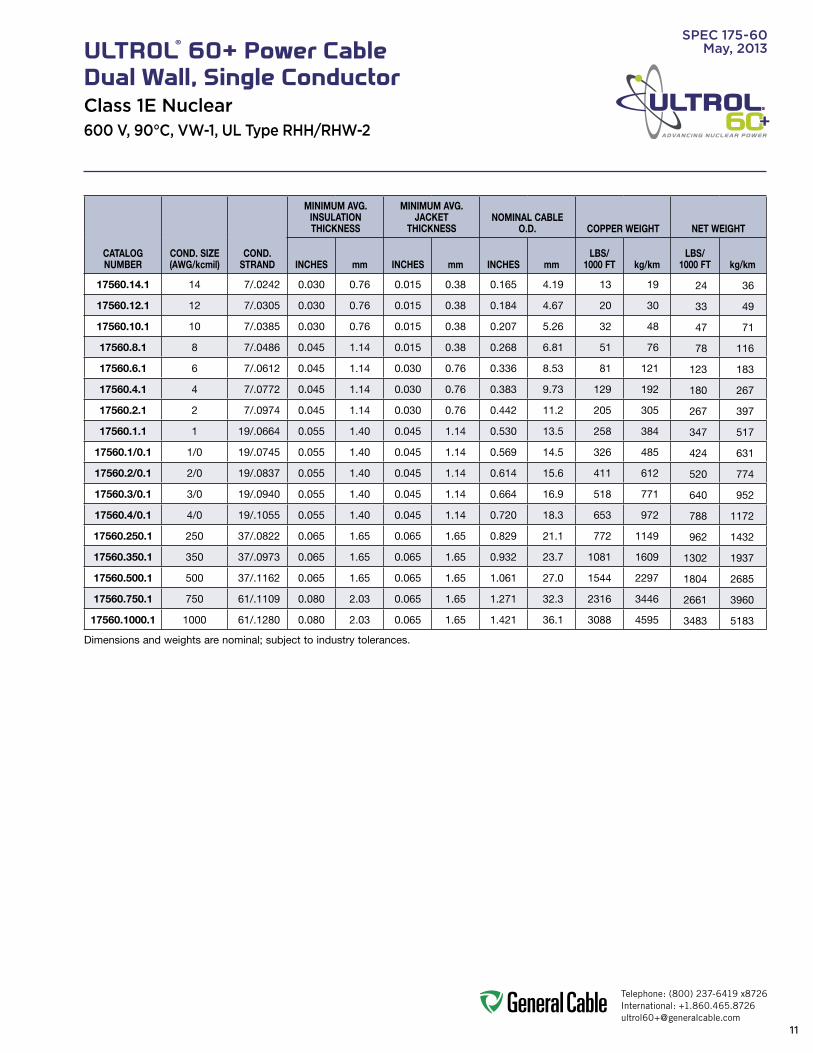
SpEC 175-60May, 2013ULTROL® 60+ Power Cable
Dual Wall, Single ConductorClass 1E Nuclear600 v, 90°C, vW-1, UL Type RHH/RHW-2
1. Conductor:• 14AWGthru1000kcmiltinnedannealed
copperperASTMB33;ClassBstrandingperASTMB8
2. Insulation:• Flame-retardant,heat-,moisture-and
radiation-resistant,thermosetULTROL®60+Cross-linkedPolyethylene(FR-XLPE)
• ColorCode:White
3. Jacket:• Flame-retardant,moisture-,oil-,sunlight-
andradiation-resistant,thermosetULTROL®60+Cross-linkedPolyolefin(XLPO)—Black
print:• For14AWGthru4/0AWG:
GENERALCABLE(WC)ULTROL®60+1/CXXAWGCOPPERFR-XLPE(UL)TYPERHH/RHW-2600V90˚CVW-1NUCLEARDAYMONTHYEAR
*Note:Sizes1/0AWG&largerinclude:SUNRESFORCTUSE,TRACEABILITYNUMBER&SEQUENTIALFOOTAGEMARK
• 250kcmilTHRU1000kcmil: GENERALCABLE(WC)ULTROL®60+1/CXXXKCMILCOPPERFR-XLPE(UL)TYPERHH/RHW-2600V90˚CSUNRESFORCTUSEVW-1NUCLEARDAYMONTHYEARTRACEABILITYNUMBERSEQUENTIALFOOTAGEMARK
Options:• Conductorstranding• ISOMetricconductor
Applications:• ULTROL®60+powercableisa600Vdual
wall, insulated single conductor, thermoset, Class1Eratedwireconstructionspecificallydesigned for applications in nuclear generating stations and where additional jacket protection is required
• ForuseinClass1Elow-voltagepowerand lighting functions where optimum performanceisrequiredandwhereflameretardancy is critical
• Maybeinstalledintrays,conduit,ducts, or direct buried
Features:• Ratedat90˚Cwetordry• Fullytraceable• Qualifiedfor60-yearservicelife• Gammaandbetaradiationresistant
(upto350megarads)• Submergenceoperability• Long-termthermalenduranceandsuperior
electricals • Excellentmechanicalcut-throughproperties• Long-termmoistureandradiationstability• Freestrippingforeaseoftermination• Meetscoldbendtestat-40°C
Industry Compliances:• Class1EQualifiedinaccordancewithIEEE
323-1974/2003andIEEE383-1974/2003• ICEAS-95-658• UL44RHH/RHW-2
Flame Test Compliances:• IEEE383:1974• IEEE383:2003• ICEAT-29-520• IEEE1202/FT4-1991,Aged&Unaged• VW-1
Other:• Qualityassuranceprograminaccordance
withNRC10CFR50AppendixB• ANSIN45.2• ASMENQA-1• NIAC• NUPIC
packaging:• Materialtobeshippedonnon-returnable
wooden reels
2
3
1
Telephone: (800) 237-6419 x8726International: [email protected]
11
ADVANCING NUCLEAR POWER
SpEC 175-60May, 2013ULTROL® 60+ Power Cable
Dual Wall, Single ConductorClass 1E Nuclear600 v, 90°C, vW-1, UL Type RHH/RHW-2
CATALOG NUMBER
COND. SIZE (AWG/kcmil)
COND. STRAND
MINIMUM AVG.INSULATIONTHICKNESS
MINIMUM AVG.JACKET
THICKNESSNOMINAL CABLE
O.D. COPPER WEIGHT NET WEIGHT
INCHES mm INCHES mm INCHES mmLBS/
1000 FT kg/kmLBS/
1000 FT kg/km
17560.14.1 14 7/.0242 0.030 0.76 0.015 0.38 0.165 4.19 13 19 24 36
17560.12.1 12 7/.0305 0.030 0.76 0.015 0.38 0.184 4.67 20 30 33 49
17560.10.1 10 7/.0385 0.030 0.76 0.015 0.38 0.207 5.26 32 48 47 71
17560.8.1 8 7/.0486 0.045 1.14 0.015 0.38 0.268 6.81 51 76 78 116
17560.6.1 6 7/.0612 0.045 1.14 0.030 0.76 0.336 8.53 81 121 123 183
17560.4.1 4 7/.0772 0.045 1.14 0.030 0.76 0.383 9.73 129 192 180 267
17560.2.1 2 7/.0974 0.045 1.14 0.030 0.76 0.442 11.2 205 305 267 397
17560.1.1 1 19/.0664 0.055 1.40 0.045 1.14 0.530 13.5 258 384 347 517
17560.1/0.1 1/0 19/.0745 0.055 1.40 0.045 1.14 0.569 14.5 326 485 424 631
17560.2/0.1 2/0 19/.0837 0.055 1.40 0.045 1.14 0.614 15.6 411 612 520 774
17560.3/0.1 3/0 19/.0940 0.055 1.40 0.045 1.14 0.664 16.9 518 771 640 952
17560.4/0.1 4/0 19/.1055 0.055 1.40 0.045 1.14 0.720 18.3 653 972 788 1172
17560.250.1 250 37/.0822 0.065 1.65 0.065 1.65 0.829 21.1 772 1149 962 1432
17560.350.1 350 37/.0973 0.065 1.65 0.065 1.65 0.932 23.7 1081 1609 1302 1937
17560.500.1 500 37/.1162 0.065 1.65 0.065 1.65 1.061 27.0 1544 2297 1804 2685
17560.750.1 750 61/.1109 0.080 2.03 0.065 1.65 1.271 32.3 2316 3446 2661 3960
17560.1000.1 1000 61/.1280 0.080 2.03 0.065 1.65 1.421 36.1 3088 4595 3483 5183
Dimensions and weights are nominal; subject to industry tolerances.

Telephone: (800) 237-6419 x8726International: [email protected]
12
ADVANCING NUCLEAR POWER
radIaTIoN-resIsTaNT
SpEC 185-60May, 2013ULTROL® 60+ Thermocouple Extension Cable
Individually Shielded Pairs, Overall ShieldClass 1E Nuclear600 v, 90°C, vW-1
1. Conductor:• 18AWGand16AWGannealed,solid
thermocouple extension grade alloys calibrated to standard limits of error per ANSI-MC96.1,latestedition
2. Insulation:• Flame-retardant,heat-,moisture-and
radiation-resistant,thermosetULTROL®60+Cross-linkedPolyethylene(FR-XLPE)
3. Conductor Components:• Insulatedsingleconductorsarematched
and twisted into pairs
4. Color Code:• Negativeconductorisred;positive
conductoriscolorcodedperANSI-MC96.1asfollows:
Type pos. Cond Overall Jacket JX White Black EX Purple Black KX Yellow Black TX Blue Black• Inmulti-paircables,pairnumberisprinted
alpha-numerically on the positive conductor
5. Cable Core:• Conductorcomponentsarecableswith
non-hygroscopic fillers and an overall binder tape as necessary
6. Shields:• Individuallyshielded:pairsare100%
shielded,helicallyappliedwithacopper/polyester tape in contact with a stranded tinned copper drain wire and an overall polyester electrical isolation tape
• Overallshield:copper/polyestertapeincontact with a stranded tinned copper drain wire
7. Jacket:• Flame-retardant,moisture-,oil-,sunlight-
andradiation-resistantthermoset,ULTROL®60+Cross-linkedPolyolefin(XLPO)—Black
print:• GENERALCABLE(WC)ULTROL®60+XX/
PRXXAWGTYPEEXORJXORKXORTXFR-XLPEXLPOSHIELDED600V90°CDAYMONTHYEARTRACEABILITYNUMBERSEQUENTIALFOOTAGEMARK
Applications:• ULTROL®60+thermocoupleextension
cableisa600Vindividualshieldedpairswithanoverallshield,thermoset,Class1Erated construction specifically designed for applications in nuclear generating stations
• Designedforuseoncriticalcircuitswheretotal isolation is required between pairs and from external interference
• Canbeinstalledintrays,conduit,ducts, or in direct burial applications
Features:• Ratedat90˚Cwetordry• Fullytraceable• Qualifiedfor60-yearservicelife• GammaandBetaradiationresistant
(upto350megarads)• Submergenceoperability• Long-termthermalenduranceandsuperior
electricals • Excellentmechanicalcut-throughproperties• Long-termmoistureandradiationstability• Freestrippingforeaseoftermination• Meetscoldbendtestat-40°C
Industry Compliances:• Class1EQualifiedinaccordancewithIEEE
323-1974/2003andIEEE383-1974/2003• ICEAS-73-532• ANSIMC96.1
Flame Test Compliances:• IEEE383:1974• IEEE383:2003• ICEAT-29-520• IEEE1202/FT4-1991,Aged&Unaged• VW-1
Other:• Qualityassuranceprograminaccordance
withNRC10CFR50AppendixB• ANSIN45.2• ASMENQA-1• NIAC• NUPIC
packaging:• Materialtobeshippedonnon-returnable
wooden reels
2
34 & 5
6
7
1 Product Construction
class
1EraTed
class 1eFlaMe-
reTardaNTMoIsTure-resIsTaNT
uV/suNlIGHT-resIsTaNT
oIl-resIsTaNT cold beNd
-40˚C
cross-lINked cuT-THrouGH

Telephone: (800) 237-6419 x8726International: [email protected]
13
ADVANCING NUCLEAR POWER
SpEC 185-60May, 2013ULTROL® 60+ Thermocouple Extension Cable
Individually Shielded Pairs, Overall ShieldClass 1E Nuclear600 v, 90°C, vW-1
CONDUCTOR TyPE CONDUCTOR SIZE (AWG) NO. OF PAIRSMIN. AVG. INSULATION THICKNESS (INCHES) DRAIN WIRE SIZE (AWG)
MIN. AVG. JACKET THICKNESS (INCHES)
JX, EX, KX, TX 18 and 16 1 - 12 .025 18 and 20 .045

Telephone: (800) 237-6419 x8726International: [email protected]
14
ADVANCING NUCLEAR POWER
radIaTIoN-resIsTaNT
SpEC 200-60May, 2013ULTROL® 60+ Instrumentation Cable
Multi-ConductorClass 1E Nuclear600 v, 90°C, vW-1
1. Conductor:• 18AWGand16AWGtinnedannealed
copperperASTMB33;ClassBstrandingperASTMB8
2. Insulation:• Flame-retardant,heat-,moisture-and
radiation-resistant,thermosetULTROL®60+Cross-linkedPolyethylene(FR-XLPE)
• Colorcode:PerICEAMethod1,TableE-1
3. Jacket:• Flame-retardant,moisture-,oil-,sunlight-,
andradiation-resistant,thermosetULTROL®60+Cross-linkedPolyolefin(XLPO)—Black
print:• GENERALCABLE(WC)ULTROL®60+
XX/CXXAWGCOPPERFR-XLPEXLPO600V90°CSUNRESOILRESI&IIDIRBURNUCLEARDAYMONTHYEARTRACEABILITYNUMBERSEQUENTIALFOOTAGEMARK
Options:• Conductorstranding• ISOMetricconductors
Applications:• ULTROL®60+instrumentationcableisa
600Vmulti-conductor,thermoset,Class1Erated construction specifically designed for applications in nuclear generating stations andwhereflameretardancyiscritical
• ForuseinClass1Emonitoringdatarecording and transmitting information on low energy circuits where shielding from external electrostatic interference is not required
• Canbeinstalledintrays,conduit,ducts, or in direct burial applications
Features:• Ratedat90°Cwetordry• Fullytraceable• Qualifiedfor60-yearservicelife• Gammaandbetaradiationresistant
(upto350megarads)• Submergenceoperability• Long-termthermalenduranceandsuperior
electricals • Excellentmechanicalcut-throughproperties• Long-termmoistureandradiationstability• Freestrippingforeaseoftermination• Meetscoldbendtestat-40°C
Industry Compliances:• Class1EQualifiedinaccordancewithIEEE
323-1974/2003andIEEE383-1974/2003• ICEAS-73-532
Flame Test Compliances:• IEEE383:1974• IEEE383:2003• ICEAT-29-520• IEEE1202/FT4-1991,Aged&Unaged• VW-1
Other:• Qualityassuranceprograminaccordance
withNRC10CFR50AppendixB• ANSIN45.2• ASMENQA-1• NIAC• NUPIC
packaging:• Materialtobeshippedonnon-returnable
wooden reels
Product Construction
class
1EraTed
class 1eFlaMe-
reTardaNTMoIsTure-resIsTaNT
uV/suNlIGHT-resIsTaNT
oIl-resIsTaNT cold beNd
-40˚C
cross-lINked cuT-THrouGH
2
3
1

Telephone: (800) 237-6419 x8726International: [email protected]
15
ADVANCING NUCLEAR POWER
SpEC 200-60May, 2013ULTROL® 60+ Instrumentation Cable
Multi-ConductorClass 1E Nuclear600 v, 90°C, vW-1
CATALOGNUMBER
NO. OF COND.
COND.SIZE
(AWG)COND.
STRAND
MINIMUM AVG. INSULATIONTHICKNESS
MINIMUM AVG.JACKET
THICKNESSNOMINAL CABLE
O.D. COPPER WEIGHT NET WEIGHT
INCHES mm INCHES mm INCHES mmLBS/
1000 FT kg/kmLBS/
1000 FT kg/km
20060.18.2 2 18 7/.0152 0.025 0.64 0.045 1.14 0.305 7.75 10 15 55 82
20060.18.3 3 18 7/.0152 0.025 0.64 0.045 1.14 0.315 8.00 15 23 61 90
20060.18.4 4 18 7/.0152 0.025 0.64 0.045 1.14 0.340 8.64 20 30 76 113
20060.18.5 5 18 7/.0152 0.025 0.64 0.045 1.14 0.370 9.40 25 38 84 125
20060.18.7 7 18 7/.0152 0.025 0.64 0.045 1.14 0.400 10.16 35 53 104 155
20060.18.9 9 18 7/.0152 0.025 0.64 0.045 1.14 0.460 11.68 46 68 129 193
20060.18.12 12 18 7/.0152 0.025 0.64 0.045 1.14 0.515 13.08 51 76 165 246
20060.18.19 19 18 7/.0152 0.025 0.64 0.060 1.52 0.630 16.00 96 143 255 380
20060.18.25 25 18 7/.0152 0.025 0.64 0.060 1.52 0.730 18.54 127 189 327 486
20060.18.30 30 18 7/.0152 0.025 0.64 0.060 1.52 0.765 19.43 151 225 372 554
20060.18.37 37 18 7/.0152 0.025 0.64 0.060 1.52 0.830 21.05 188 280 451 671
20060.16.2 2 16 7/.0192 0.025 0.64 0.045 1.14 0.320 8.13 16 24 59 88
20060.16.3 3 16 7/.0192 0.025 0.64 0.045 1.14 0.335 8.51 24 36 73 108
20060.16.4 4 16 7/.0192 0.025 0.64 0.045 1.14 0.365 9.27 32 48 90 134
20060.16.5 5 16 7/.0192 0.025 0.64 0.045 1.14 0.395 10.03 40 60 104 155
20060.16.7 7 16 7/.0192 0.025 0.64 0.045 1.14 0.430 10.92 57 84 135 201
20060.16.9 9 16 7/.0192 0.025 0.64 0.045 1.14 0.500 12.70 73 108 169 251
20060.16.12 12 16 7/.0192 0.025 0.64 0.060 1.52 0.590 15.00 97 145 233 346
20060.16.19 19 16 7/.0192 0.025 0.64 0.060 1.52 0.680 17.27 154 229 335 498
20060.16.25 25 16 7/.0192 0.025 0.64 0.060 1.52 0.790 20.07 203 302 427 636
20060.16.30 30 16 7/.0192 0.025 0.64 0.060 1.52 0.880 22.35 244 363 543 807
20060.16.37 37 16 7/.0192 0.025 0.64 0.080 2.03 0.945 24.00 300 447 648 964
Insulated conductor diameter (inches) 18 AWG (.10) and 16 AWG (.11).Dimensions and weights are nominal; subject to industry tolerances.
Telephone: (800) 237-6419 x8726International: [email protected]
16
ADVANCING NUCLEAR POWER
radIaTIoN-resIsTaNT
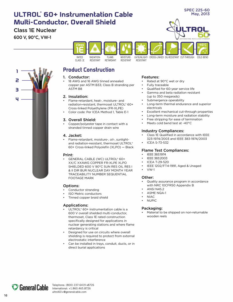
SpEC 225-60May, 2013ULTROL® 60+ Instrumentation Cable
Multi-Conductor, Overall ShieldClass 1E Nuclear600 v, 90°C, vW-1
1. Conductor:• 18AWGand16AWGtinnedannealed
copperperASTMB33;ClassBstrandingperASTMB8
2. Insulation:• Flame-retardant,heat-,moisture-and
radiation-resistant,thermosetULTROL®60+Cross-linkedPolyethylene(FR-XLPE)
• Colorcode:PerICEAMethod1,TableE-1
3. Overall Shield:• Copper/polyestertapeincontactwitha
stranded tinned copper drain wire
4. Jacket:• Flame-retardant,moisture-,oil-,sunlight-
andradiation-resistant,thermosetULTROL®60+Cross-linkedPolyolefin(XLPO)—Black
print:• GENERALCABLE(WC)ULTROL®60+
XX/CXXAWGCOPPERFR-XLPEXLPOSHIELDED600V90°CSUNRESOILRESI&IIDIRBURNUCLEARDAYMONTHYEARTRACEABILITYNUMBERSEQUENTIALFOOTAGEMARK
Options:• Conductorstranding• ISOMetricconductors• Tinnedcopperbraidshield
Applications:• ULTROL®60+instrumentationcableisa
600Voverallshieldedmulti-conductor,thermoset,Class1Eratedconstructionspecifically designed for applications in nucleargeneratingstationsandwhereflameretardancy is critical
• Designedforuseoncircuitswhereoverallshielding is required to protect from external electrostatic interference
• Canbeinstalledintrays,conduit,ducts,orindirect burial applications
Features:• Ratedat90°Cwetordry• Fullytraceable• Qualifiedfor60-yearservicelife• Gammaandbetaradiationresistant
(upto350megarads)• Submergenceoperability• Long-termthermalenduranceandsuperior
electricals • Excellentmechanicalcut-throughproperties• Long-termmoistureandradiationstability• Freestrippingforeaseoftermination• Meetscoldbendtestat-40°C
Industry Compliances:• Class1EQualifiedinaccordancewithIEEE
323-1974/2003andIEEE383-1974/2003• ICEAS-73-532
Flame Test Compliances:• IEEE383:1974• IEEE383:2003• ICEAT-29-520• IEEE1202/FT4-1991,Aged&Unaged• VW-1
Other:• Qualityassuranceprograminaccordance
withNRC10CFR50AppendixB• ANSIN45.2• ASMENQA-1• NIAC• NUPIC
packaging:• Materialtobeshippedonnon-returnable
wooden reels
Product Construction
class
1EraTed
class 1eFlaMe-
reTardaNTMoIsTure-resIsTaNT
uV/suNlIGHT-resIsTaNT
oIl-resIsTaNT cold beNd
-40˚C
cross-lINked cuT-THrouGH
2
4
3
1

Telephone: (800) 237-6419 x8726International: [email protected]
17
ADVANCING NUCLEAR POWER
SpEC 225-60May, 2013ULTROL® 60+ Instrumentation Cable
Multi-Conductor, Overall ShieldClass 1E Nuclear600 v, 90°C, vW-1
CATALOGNUMBER
NO. OF COND.
COND.SIZE
(AWG)COND.
STRAND
MINIMUM AVG.INSULATIONTHICKNESS
DRAINWIRE SIZE
(AWG)
MINIMUM AVG.JACKET
THICKNESSNOMINAL CABLE
O.D. COPPER WEIGHT NET WEIGHT
INCHES mm INCHES mm INCHES mmLBS/
1000 FT kg/kmLBS/
1000 FT kg/km
22560.18.2 2 18 7/.0152 0.025 0.64 20 0.045 1.14 0.291 7.39 13 20 57 85
22560.18.3 3 18 7/.0152 0.025 0.64 20 0.045 1.14 0.306 7.77 18 27 60 90
22560.18.4 4 18 7/.0152 0.025 0.64 20 0.045 1.14 0.332 8.43 23 35 79 117
22560.18.5 5 18 7/.0152 0.025 0.64 20 0.045 1.14 0.399 10.1 29 42 85 127
22560.18.7 7 18 7/.0152 0.025 0.64 20 0.045 1.14 0.428 10.9 39 57 106 158
22560.18.9 9 18 7/.0152 0.025 0.64 20 0.045 1.14 0.488 12.4 49 73 132 196
22560.18.12 12 18 7/.0152 0.025 0.64 20 0.045 1.14 0.557 14.2 64 96 164 244
22560.18.19 19 18 7/.0152 0.025 0.64 20 0.060 1.52 0.654 16.6 99 148 257 382
22560.18.25 25 18 7/.0152 0.025 0.64 20 0.060 1.52 0.747 19.0 130 194 327 487
22560.18.30 30 18 7/.0152 0.025 0.64 20 0.060 1.52 0.793 20.1 155 231 377 561
22560.18.37 37 18 7/.0152 0.025 0.64 20 0.080 2.03 0.890 22.6 191 284 449 668
22560.16.2 2 16 7/.0192 0.025 0.64 18 0.045 1.14 0.309 7.85 21 32 64 96
22560.16.3 3 16 7/.0192 0.025 0.64 18 0.045 1.14 0.325 8.26 29 44 77 114
22560.16.4 4 16 7/.0192 0.025 0.64 18 0.045 1.14 0.353 8.97 37 56 93 138
22560.16.5 5 16 7/.0192 0.025 0.64 18 0.045 1.14 0.433 11.0 46 68 109 162
22560.16.7 7 16 7/.0192 0.025 0.64 18 0.045 1.14 0.465 11.8 62 92 137 204
22560.16.9 9 16 7/.0192 0.025 0.64 18 0.060 1.52 0.561 14.3 78 116 170 253
22560.16.12 12 16 7/.0192 0.025 0.64 18 0.060 1.52 0.620 15.8 103 153 235 349
22560.16.19 19 16 7/.0192 0.025 0.64 18 0.060 1.52 0.711 18.1 159 237 337 501
22560.16.25 25 16 7/.0192 0.025 0.64 18 0.060 1.52 0.814 20.7 208 310 430 640
22560.16.30 30 16 7/.0192 0.025 0.64 18 0.080 2.03 0.904 23.0 249 371 542 806
22560.16.37 37 16 7/.0192 0.025 0.64 18 0.080 2.03 0.967 24.6 305 454 643 957
Insulated conductor diameter (inches) 18 AWG (.10) and 16 AWG (.11).Dimensions and weights are nominal; subject to industry tolerances.

Telephone: (800) 237-6419 x8726International: [email protected]
18
ADVANCING NUCLEAR POWER
SpEC 250-60May, 2013ULTROL® 60+ Instrumentation Cable
Individually Shielded Pairs or TriadsOverall ShieldClass 1E Nuclear600 v, 90°C, vW-1
1. Conductor: • 18AWGand16AWGtinnedannealed
copperperASTMB33;ClassBstranding perASTMB8
2. Insulation:• Flame-retardant,heat-,moisture-and
radiation-resistant,thermosetULTROL®60+Cross-linkedPolyethylene(FR-XLPE)
• Colorcode:PerICEAMethod1—Pairs:blackandwhite;Triads:black,whiteandred.Oneconductorineachpair/triadisprintedalpha-numerically for easy identification
3. Shields:• Individuallyshielded:pairsortriadsare
100%shieldedwithacopper/polyestertapein contact with a stranded tinned copper drain wire and an overall polyester electrical isolation tape
• Overallshield:copper/polyestertapeincontact with a stranded tinned copper drain wire
4. Jacket:• Flame-retardant,moisture-,oil-,sunlight-
andradiation-resistant,thermosetULTROL®60+Cross-linkedPolyolefin(XLPO)—Black
print: • GENERALCABLE(WC)ULTROL®60+
XX/PRORTRIADSXXAWGCOPPERFR-XLPEXLPOSHIELDED600V90°CSUNRESOILRESI&IIDIRBURNUCLEARDAYMONTHYEARTRACEABILITYNUMBERSEQUENTIALFOOTAGEMARK
Options:• Conductorstranding• ISOMetricconductors• Tinnedcopperbraidshield
Applications:• ULTROL®60+instrumentationcableisa
600Vindividualshieldedpairsortriadswithoverallshield,thermoset,Class1Erated construction specifically designed for applications in nuclear generating stations andwhereflameretardancyiscritical
Applications (cont’d):• Designedforuseoncriticalcircuitswhere
totalisolationisrequiredbetweenpairs/triads and from external interference
• Canbeinstalledintrays,conduit,ducts, or in direct burial applications
Features:• Ratedat90˚Cwetordry• Fullytraceable• Qualifiedfor60-yearservicelife• Gammaandbetaradiationresistant
(upto350megarads)• Submergenceoperability• Long-termthermalenduranceandsuperior
electricals • Excellentmechanicalcut-throughproperties• Long-termmoistureandradiationstability• Freestrippingforeaseoftermination• Meetscoldbendtestat-40°C
Industry Compliances:• Class1EQualifiedinaccordancewithIEEE
323-1974/2003andIEEE383-1974/2003• ICEAS-73-532
Flame Test Compliances:• IEEE383:1974• IEEE383:2003• ICEAT-29-520• IEEE1202/FT4-1991,Aged&Unaged• VW-1
Other:• Qualityassuranceprograminaccordance
withNRC10CFR50AppendixB• ANSIN45.2• ASMENQA-1• NIAC• NUPIC
packaging:• Materialtobeshippedonnon-returnable
wooden reels
Product Construction
class
1EraTed
class 1eFlaMe-
reTardaNTMoIsTure-resIsTaNT
uV/suNlIGHT-resIsTaNT
oIl-resIsTaNT cold beNd
-40˚C
cross-lINked cuT-THrouGHradIaTIoN-resIsTaNT
2
4
3
1

Telephone: (800) 237-6419 x8726International: [email protected]
19
ADVANCING NUCLEAR POWER
SpEC 250-60May, 2013ULTROL® 60+ Instrumentation Cable
Individually Shielded Pairs or TriadsOverall ShieldClass 1E Nuclear600 v, 90°C, vW-1
CATALOGNUMBER
NO. OFPAIRS/ TRIADS
COND.SIZE
(AWG)COND.
STRAND
MINIMUM AVG.INSULATIONTHICKNESS
DRAINWIRE SIZE
(AWG)
MINIMUM AVG.JACKET
THICKNESSNOMINAL CABLE
O.D. COPPER WEIGHT NET WEIGHT
INCHES mm INCHES mm INCHES mmLBS/
1000 FT kg/kmLBS/
1000 FT kg/km
25060.18.2P 2 SPS 18 7/.0152 0.025 0.64 20 0.045 1.14 0.462 11.7 30 45 140 208
25060.18.3P 3 SPS 18 7/.0152 0.025 0.64 20 0.045 1.14 0.490 12.5 43 65 173 257
25060.18.4P 4 SPS 18 7/.0152 0.025 0.64 20 0.060 1.52 0.567 14.4 57 85 245 365
25060.18.5P 5 SPS 18 7/.0152 0.025 0.64 20 0.060 1.52 0.619 15.7 70 105 290 432
25060.18.7P 7 SPS 18 7/.0152 0.025 0.64 20 0.060 1.52 0.673 17.1 97 145 313 465
25060.18.9P 9 SPS 18 7/.0152 0.025 0.64 20 0.060 1.52 0.784 19.9 125 186 389 579
25060.18.12P 12 SPS 18 7/.0152 0.025 0.64 20 0.080 2.03 0.923 23.4 165 246 536 798
25060.18.19P 19 SPS 18 7/.0152 0.025 0.64 20 0.080 2.03 1.077 27.4 259 385 708 1054
25060.16.2P 2 SPS 16 7/.0192 0.025 0.64 18 0.045 1.14 0.495 12.6 48 71 180 268
25060.16.3P 3 SPS 16 7/.0192 0.025 0.64 18 0.060 1.52 0.556 14.1 69 103 239 356
25060.16.4P 4 SPS 16 7/.0192 0.025 0.64 18 0.060 1.52 0.608 15.4 91 135 307 456
25060.16.5P 5 SPS 16 7/.0192 0.025 0.64 18 0.060 1.52 0.665 16.9 113 168 370 550
25060.16.7P 7 SPS 16 7/.0192 0.025 0.64 18 0.060 1.52 0.725 18.4 156 232 401 597
25060.16.9P 9 SPS 16 7/.0192 0.025 0.64 18 0.080 2.03 0.887 22.5 199 296 551 820
25060.16.12P 12 SPS 16 7/.0192 0.025 0.64 18 0.080 2.03 0.996 25.3 264 393 694 1033
25060.16.19P 19 SPS 16 7/.0192 0.025 0.64 18 0.080 2.03 1.164 29.6 414 616 935 1391
25060.18.2T 2 STS 18 7/.0152 0.025 0.64 20 0.045 1.14 0.489 12.4 40 60 188 280
25060.18.3T 3 STS 18 7/.0152 0.025 0.64 20 0.045 1.14 0.519 13.2 59 87 235 350
25060.18.4T 4 STS 18 7/.0152 0.025 0.64 20 0.060 1.52 0.599 15.2 77 115 337 502
25060.18.5T 5 STS 18 7/.0152 0.025 0.64 20 0.060 1.52 0.655 16.6 96 143 398 593
25060.18.7T 7 STS 18 7/.0152 0.025 0.64 20 0.060 1.52 0.714 18.1 133 198 433 645
25060.18.9T 9 STS 18 7/.0152 0.025 0.64 20 0.060 1.52 0.833 21.2 170 253 533 794
25060.18.12T 12 STS 18 7/.0152 0.025 0.64 20 0.080 2.03 0.979 24.9 226 336 741 1102
25060.18.19T 19 STS 18 7/.0152 0.025 0.64 20 0.080 2.03 1.145 29.1 356 530 977 1454
25060.16.2T 2 STS 16 7/.0192 0.025 0.64 18 0.060 1.52 0.554 14.1 64 96 241 359
25060.16.3T 3 STS 16 7/.0192 0.025 0.64 18 0.060 1.52 0.587 14.9 94 139 325 484
25060.16.4T 4 STS 16 7/.0192 0.025 0.64 18 0.060 1.52 0.642 16.3 124 185 423 630
25060.16.5T 5 STS 16 7/.0192 0.025 0.64 18 0.060 1.52 0.704 17.9 154 229 506 752
25060.16.7T 7 STS 16 7/.0192 0.025 0.64 18 0.060 1.52 0.768 19.5 213 317 553 823
25060.16.9T 9 STS 16 7/.0192 0.025 0.64 18 0.080 2.03 0.939 23.9 272 405 762 1134
25060.16.12T 12 STS 16 7/.0192 0.025 0.64 18 0.080 2.03 1.055 26.8 361 537 958 1425
25060.16.19T 19 STS 16 7/.0192 0.025 0.64 18 0.080 2.03 1.236 31.4 569 847 1287 1916
Insulated conductor diameter (inches) 18 AWG (.10) and 16 AWG (.11).Dimensions and weights are nominal; subject to industry tolerances.

Telephone: (800) 237-6419 x8726International: [email protected]
20
ADVANCING NUCLEAR POWER
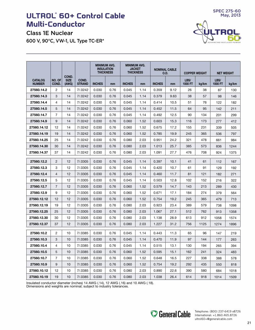
SpEC 275-60May, 2013ULTROL® 60+ Control Cable
Multi-ConductorClass 1E Nuclear600 v, 90°C, vW-1, UL Type TC-ER*
1. Conductor:• 14AWGthru10AWGtinnedannealed
copper;ClassBstranding;2thru37conductors
2. Insulation:• Flame-retardant,heat-,moisture-and
radiation-resistant,thermosetULTROL®60+Cross-linkedPolyethylene(FR-XLPE)
• Colorcode:PerICEAMethod1,TableE-1
3. Jacket:• Flame-retardant,moisture-,oil-,sunlight-
andradiation-resistant,thermosetULTROL®60+Cross-linkedPolyolefin(XLPO)—Black
print:• GENERALCABLE(WC)ULTROL®60+XX/C
XXAWGCOPPERFR-XLPEXLPO600V90°CSUNRESOILRESI&IIDIRBUR(UL)TYPE-TC-ER*XHHW-2VW-1NUCLEARDAYMONTHYEARTRACEABILITYNUMBERSEQUENTIALFOOTAGEMARK *-ERfor>2conductors
Options:• Conductorstranding• ISOMetricconductors• E-2colorcode
Applications:• ULTROL®60+controlcableisa600V
multi-conductor,thermoset,Class1Eratedconstruction specifically designed for applications in nuclear generating stations andwhereflameretardancyiscritical
• ForuseinClass1Epowerdistributionandcontrol circuits for power lighting, control and signal circuits
• Canbeinstalledintrays,conduit,ducts, or in direct burial applications
Features:• Ratedat90˚Cwetordry• Fullytraceable• Qualifiedfor60-yearservicelife• Gammaandbetaradiationresistant
(upto350megarads)• Submergenceoperability• Long-termthermalenduranceandsuperior
electricals• Excellentmechanicalcut-throughproperties• Long-termmoistureandradiationstability• Freestrippingforeaseoftermination• Meetscoldbendtestat-40°C
Industry Compliances:• Class1EQualifiedinaccordancewithIEEE
323-1974/2003andIEEE383-1974/2003• ICEAS-73-532• UL1277TypeTC-ER*• UL44XHHW-2
*-ERfor>2conductors
Flame Test Compliances:• IEEE383:1974• IEEE383:2003• ICEAT-29-520• IEEE1202/FT4-1991,Aged&Unaged• VW-1
Other:• Qualityassuranceprograminaccordance
withNRC10CFR50AppendixB• ANSIN45.2• ASMENQA-1• NIAC• NUPIC
packaging:• Materialtobeshippedonnon-returnable
wooden reels
Product Construction
class
1EraTed
class 1eFlaMe-
reTardaNTMoIsTure-resIsTaNT
uV/suNlIGHT-resIsTaNT
oIl-resIsTaNT cold beNd
-40˚C
cross-lINked cuT-THrouGHradIaTIoN-resIsTaNT
2
3
1
Telephone: (800) 237-6419 x8726International: [email protected]
21
ADVANCING NUCLEAR POWER
SpEC 275-60May, 2013ULTROL® 60+ Control Cable
Multi-ConductorClass 1E Nuclear600 v, 90°C, vW-1, UL Type TC-ER*
CATALOGNUMBER
NO. OF COND.
COND.SIZE
(AWG)COND.
STRAND
MINIMUM AVG.INSULATIONTHICKNESS
MINIMUM AVG.JACKET
THICKNESSNOMINAL CABLE
O.D. COPPER WEIGHT NET WEIGHT
INCHES mm INCHES mm INCHES mmLBS/
1000 FT kg/kmLBS/
1000 FT kg/km
27560.14.2 2 14 7/.0242 0.030 0.76 0.045 1.14 0.359 9.12 26 38 87 130
27560.14.3 3 14 7/.0242 0.030 0.76 0.045 1.14 0.379 9.63 38 57 98 146
27560.14.4 4 14 7/.0242 0.030 0.76 0.045 1.14 0.414 10.5 51 76 122 182
27560.14.5 5 14 7/.0242 0.030 0.76 0.045 1.14 0.452 11.5 64 95 142 211
27560.14.7 7 14 7/.0242 0.030 0.76 0.045 1.14 0.492 12.5 90 134 201 299
27560.14.9 9 14 7/.0242 0.030 0.76 0.060 1.52 0.603 15.3 116 173 277 412
27560.14.12 12 14 7/.0242 0.030 0.76 0.060 1.52 0.675 17.2 155 231 339 505
27560.14.19 19 14 7/.0242 0.030 0.76 0.060 1.52 0.785 19.9 245 365 536 797
27560.14.25 25 14 7/.0242 0.030 0.76 0.080 2.03 0.951 24.2 321 478 661 984
27560.14.30 30 14 7/.0242 0.030 0.76 0.080 2.03 1.013 25.7 385 573 836 1244
27560.14.37 37 14 7/.0242 0.030 0.76 0.080 2.03 1.091 27.7 476 708 924 1375
27560.12.2 2 12 7/.0305 0.030 0.76 0.045 1.14 0.397 10.1 41 61 112 167
27560.12.3 3 12 7/.0305 0.030 0.76 0.045 1.14 0.420 10.7 61 91 129 192
27560.12.4 4 12 7/.0305 0.030 0.76 0.045 1.14 0.460 11.7 81 121 182 271
27560.12.5 5 12 7/.0305 0.030 0.76 0.045 1.14 0.503 12.8 102 152 216 322
27560.12.7 7 12 7/.0305 0.030 0.76 0.060 1.52 0.579 14.7 143 213 289 430
27560.12.9 9 12 7/.0305 0.030 0.76 0.060 1.52 0.671 17.1 184 274 379 564
27560.12.12 12 12 7/.0305 0.030 0.76 0.060 1.52 0.754 19.2 245 365 479 713
27560.12.19 19 12 7/.0305 0.030 0.76 0.080 2.03 0.923 23.4 389 579 738 1098
27560.12.25 25 12 7/.0305 0.030 0.76 0.080 2.03 1.067 27.1 512 762 913 1358
27560.12.30 30 12 7/.0305 0.030 0.76 0.080 2.03 1.138 28.9 613 912 1058 1574
27560.12.37 37 12 7/.0305 0.030 0.76 0.080 2.03 1.227 31.2 756 1125 1274 1896
27560.10.2 2 10 7/.0385 0.030 0.76 0.045 1.14 0.443 11.3 65 96 147 219
27560.10.3 3 10 7/.0385 0.030 0.76 0.045 1.14 0.470 11.9 97 144 177 263
27560.10.4 4 10 7/.0385 0.030 0.76 0.045 1.14 0.515 13.1 130 194 265 394
27560.10.5 5 10 7/.0385 0.030 0.76 0.060 1.52 0.595 15.1 162 241 324 483
27560.10.7 7 10 7/.0385 0.030 0.76 0.060 1.52 0.648 16.5 227 338 388 578
27560.10.9 9 10 7/.0385 0.030 0.76 0.060 1.52 0.754 19.2 292 435 550 818
27560.10.12 12 10 7/.0385 0.030 0.76 0.080 2.03 0.890 22.6 390 580 684 1018
27560.10.19 19 10 7/.0385 0.030 0.76 0.080 2.03 1.038 26.4 614 918 1014 1509
Insulated conductor diameter (inches) 14 AWG (.14), 12 AWG (.16) and 10 AWG (.18). Dimensions and weights are nominal; subject to industry tolerances.

Telephone: (800) 237-6419 x8726International: [email protected]
22
ADVANCING NUCLEAR POWER
SpEC 300-60May, 2013ULTROL® 60+ Control Cable
Multi-Conductor, Overall ShieldClass 1E Nuclear600 v, 90°C, vW-1, UL Type TC-ER*
1. Conductor:• 14AWGthru10AWG,tinnedannealed
copper;ClassBstranding;2thru37conductors
2. Insulation:• Flame-retardant,heat-,moisture-and
radiation-resistant,thermosetULTROL®60+Cross-linkedPolyethylene(FR-XLPE)
• Colorcode:perICEAMethod1,TableE-1
3. Overall Shield:• Copper/polyestertapeincontactwitha
stranded tinned copper drain wire
4. Jacket:• Flame-retardant,moisture-,oil-,sunlight-
andradiation-resistant,thermosetULTROL®60+Cross-linkedPolyolefin(XLPO)—Black
print:• GENERALCABLE(WC)ULTROL®60+XX/C
XXAWGCOPPERFR-XLPEXLPOSHIELDED600V90°CSUNRESOILRESI&IIDIRBUR(UL)TYPETC-ER*XHHW-2VW-1NUCLEARDAYMONTHYEARTRACEABILITYNUMBERSEQUENTIALFOOTAGEMARK *-ERfor>2conductors
Options:• Conductorstranding• ISOMetricconductors• E-2colorcode• Longitudinalcorrugatedtinnedcopper
tape shield
Applications:• ULTROL®60+controlcableisa600V
overall shielded, multi-conductor, thermoset, Class1Eratedconstructionspecificallydesigned for applications in nuclear generatingstationsandwhereflameretardancy is critical
• WhereoptimumperformanceisrequiredforuseonClass1Ecircuitswhenshieldingfromexternal electrostatic interference is required
• Canbeinstalledintrays,conduit,ducts, or in direct burial applications
Features:• Ratedat90˚Cwetordry• Fullytraceable• Qualifiedfor60-yearservicelife• Gammaandbetaradiationresistant
(upto350megarads)• Submergenceoperability• Long-termthermalenduranceandsuperior
electricals• Excellentmechanicalcut-throughproperties• Long-termmoistureandradiationstability• Freestrippingforeaseoftermination• Meetscoldbendtestat-40°C
Industry Compliances:• Class1EQualifiedinaccordancewithIEEE
323-1974/2003andIEEE383-1974/2003• ICEAS-73-532• UL1277TypeTC-ER*• UL44XHHW-2
*-ERfor>2conductors
Flame Test Compliances:• IEEE383:1974• IEEE383:2003• ICEAT-29-520• IEEE1202/FT4-1991,Aged&Unaged• VW-1
Other:• Qualityassuranceprograminaccordance
withNRC10CFR50AppendixB• ANSIN45.2• ASMENQA-1• NIAC• NUPIC
packaging:• Materialtobeshippedonnon-returnable
wooden reels
Product Construction
class
1EraTed
class 1eFlaMe-
reTardaNTMoIsTure-resIsTaNT
uV/suNlIGHT-resIsTaNT
oIl-resIsTaNT cold beNd
-40˚C
cross-lINked cuT-THrouGHradIaTIoN-resIsTaNT
2
4
3
1

Telephone: (800) 237-6419 x8726International: [email protected]
23
ADVANCING NUCLEAR POWER
SpEC 300-60May, 2013ULTROL® 60+ Control Cable
Multi-Conductor, Overall ShieldClass 1E Nuclear600 v, 90°C, vW-1, UL Type TC-ER*
CATALOGNUMBER
NO. OF COND.
COND.SIZE
(AWG)COND.
STRAND
MINIMUM AVG.INSULATIONTHICKNESS
DRAINWIRE SIZE
(AWG)
MINIMUM AVG.JACKET
THICKNESSNOMINAL CABLE
O.D. COPPER WEIGHT NET WEIGHT
INCHES mm INCHES mm INCHES mmLBS/
1000 FT kg/kmLBS/
1000 FT kg/km
30060.14.2 2 14 7/.0242 0.030 0.76 16 0.045 1.14 0.359 9.12 34 50 98 145
30060.14.3 3 14 7/.0242 0.030 0.76 16 0.045 1.14 0.379 9.63 47 69 108 161
30060.14.4 4 14 7/.0242 0.030 0.76 16 0.045 1.14 0.414 10.5 59 88 134 199
30060.14.5 5 14 7/.0242 0.030 0.76 16 0.045 1.14 0.512 13.0 72 108 152 227
30060.14.7 7 14 7/.0242 0.030 0.76 16 0.060 1.52 0.582 14.8 98 146 211 313
30060.14.9 9 14 7/.0242 0.030 0.76 16 0.060 1.52 0.663 16.8 124 185 289 430
30060.14.12 12 14 7/.0242 0.030 0.76 16 0.060 1.52 0.736 18.7 163 243 352 524
30060.14.19 19 14 7/.0242 0.030 0.76 16 0.080 2.03 0.888 22.6 251 374 546 812
30060.14.25 25 14 7/.0242 0.030 0.76 16 0.080 2.03 1.014 25.8 330 491 675 1005
30060.14.30 30 14 7/.0242 0.030 0.76 16 0.080 2.03 1.076 27.3 394 586 852 1268
30060.14.37 37 14 7/.0242 0.030 0.76 16 0.080 2.03 1.154 29.3 484 720 1055 1570
30060.12.2 2 12 7/.0305 0.030 0.76 14 0.045 1.14 0.397 10.0 54 80 129 192
30060.12.3 3 12 7/.0305 0.030 0.76 14 0.045 1.14 0.420 10.7 74 110 145 216
30060.12.4 4 12 7/.0305 0.030 0.76 14 0.045 1.14 0.460 11.7 94 140 198 295
30060.12.5 5 12 7/.0305 0.030 0.76 14 0.060 1.52 0.607 15.4 115 171 229 341
30060.12.7 7 12 7/.0305 0.030 0.76 14 0.060 1.52 0.653 16.6 156 232 305 453
30060.12.9 9 12 7/.0305 0.030 0.76 14 0.060 1.52 0.745 18.9 197 293 394 587
30060.12.12 12 12 7/.0305 0.030 0.76 14 0.060 1.52 0.828 21.0 258 384 495 736
30060.12.19 19 12 7/.0305 0.030 0.76 14 0.080 2.03 0.997 25.3 401 597 754 1122
30060.12.25 25 12 7/.0305 0.030 0.76 14 0.080 2.03 1.141 29.0 525 781 929 1383
30060.12.30 30 12 7/.0305 0.030 0.76 14 0.080 2.03 1.211 30.8 626 932 1074 1599
30060.12.37 37 12 7/.0305 0.030 0.76 14 0.080 2.03 1.301 33.1 769 1144 1291 1921
30060.10.2 2 10 7/.0385 0.030 0.76 12 0.045 1.14 0.443 11.3 85 127 173 258
30060.10.3 3 10 7/.0385 0.030 0.76 12 0.045 1.14 0.470 11.9 118 176 202 301
30060.10.4 4 10 7/.0385 0.030 0.76 12 0.045 1.14 0.515 13.1 150 223 291 433
30060.10.5 5 10 7/.0385 0.030 0.76 12 0.060 1.52 0.688 17.5 183 272 349 519
30060.10.7 7 10 7/.0385 0.030 0.76 12 0.060 1.52 0.740 18.8 248 369 415 618
30060.10.9 9 10 7/.0385 0.030 0.76 12 0.080 2.03 0.887 22.5 313 466 570 849
30060.10.12 12 10 7/.0385 0.030 0.76 12 0.080 2.03 0.982 24.9 411 612 709 1055
30060.10.19 19 10 7/.0385 0.030 0.76 12 0.080 2.03 1.130 28.7 638 950 1038 1545
Insulated conductor diameter (inches) 14 AWG (.14), 12 AWG (.16) and 10 AWG (.18). Dimensions and weights are nominal; subject to industry tolerances.

Telephone: (800) 237-6419 x8726International: [email protected]
24
ADVANCING NUCLEAR POWER
SpEC 325-60May, 2013ULTROL® 60+ Power Cable
3 or 4 Conductors with GroundClass 1E Nuclear600 v, 90°C, vW-1, UL Type TC-ER
1. Conductor:• 8AWGthru750kcmiltinnedannealed
copperperASTMB33;ClassBstranding perASTMB8
2. Insulation:• Flame-retardant,heat-,moisture-and
radiation-resistant,thermosetULTROL®60+Cross-linkedPolyethylene(FR-XLPE)
• Colorcode:PerICEAMethod1,TableE-1
3. Grounding Conductor:• TinnedannealedcopperClassBstranding,
sizedaccordingtoNEC®requirements
4. Jacket:• Flame-retardant,moisture-,oil-,sunlight-
andradiation-resistantthermosetULTROL®60+Cross-linkedPolyolefin(XLPO)—Black
print:• GENERALCABLE(WC)ULTROL®60+
XX/CXXAWGWITHGRNDCOPPERFR-XLPEXLPO600V90˚CSUNRESOILRESI&IIDIRBUR(UL)TYPETC-ER*XHHW-2NUCLEARDAYMONTHYEARTRACEABILITYNUMBERSEQUENTIALFOOTAGEMARK
Options:• Conductorstranding• ISOMetricconductors• Coloredinsulation• Method4colorcode• Sectionedgroundingconductors• Longitudinalcorrugatedtinnedcopper
tape shield
Applications:• ULTROL®60+powercableisa600V
multi-conductor,thermoset,Class1Eratedconstruction specifically designed for applications in nuclear generating stations andwhereflameretardancyiscritical
• ForuseinClass1Epowerdistributionandcontrol circuits for power lighting, control and signal circuits
• Canbeinstalledintrays,conduit,ducts,orindirect burial applications
Features:• Ratedat90˚Cwetordry• Fullytraceable• Qualifiedfor60-yearservicelife• Gammaandbetaradiationresistant
(upto350megarads)• Submergenceoperability• Long-termthermalenduranceandsuperior
electricals• Excellentmechanicalcut-throughproperties• Long-termmoistureandradiationstability• Freestrippingforeaseoftermination• Meetscoldbendtestat-40°C
Industry Compliances:• Class1EQualifiedinaccordancewithIEEE
323-1974/2003andIEEE383-1974/2003• ICEAS-73-532• UL1277TypeTC-ER• UL44XHHW-2
Flame Test Compliances:• IEEE383:1974• IEEE383:2003• ICEAT-29-520• IEEE1202/FT4-1991,Aged&Unaged• VW-1
Other:• Qualityassuranceprograminaccordance
withNRC10CFR50AppendixB• ANSIN45.2• ASMENQA-1• NIAC• NUPIC
packaging:• Materialtobeshippedonspoolsonnon-
returnable wooden reels
3
Product Construction
class
1EraTed
class 1eFlaMe-
reTardaNTMoIsTure-resIsTaNT
uV/suNlIGHT-resIsTaNT
oIl-resIsTaNT cold beNd
-40˚C
cross-lINked cuT-THrouGHradIaTIoN-resIsTaNT
2
4
1

Telephone: (800) 237-6419 x8726International: [email protected]
25
ADVANCING NUCLEAR POWER
SpEC 325-60May, 2013ULTROL® 60+ Power Cable
3 or 4 Conductors with GroundClass 1E Nuclear600 v, 90°C, vW-1, UL Type TC-ER
CATALOGNUMBER
NO. OF COND.
COND.SIZE(AWG/kcmil)
COND. STRAND
MINIMUM AVG.INSULATIONTHICKNESS
GROUND WIRE SIZE
(AWG)
MINIMUM AVG.JACKET
THICKNESSNOMINAL CABLE
O.D. COPPER WEIGHT NET WEIGHT
INCHES mm INCHES mm INCHES mmLBS/
1000 FT kg/kmLBS/
1000 FT kg/km
32560.8.3 3 8 7/.0486 0.045 1.14 10 0.060 1.52 0.629 16.0 187 278 328 488
32560.8.4 4 8 7/.0486 0.045 1.14 10 0.060 1.52 0.690 17.5 238 354 406 604
32560.6.3 3 6 7/.0612 0.045 1.14 8 0.060 1.52 0.708 18.0 297 442 477 710
32560.6.4 4 6 7/.0612 0.045 1.14 8 0.060 1.52 0.779 19.8 379 564 593 882
32560.4.3 3 4 7/.0772 0.045 1.14 8 0.060 1.52 0.810 20.6 442 658 707 1052
32560.4.4 4 4 7/.0772 0.045 1.14 8 0.080 2.03 0.932 23.7 572 851 878 1306
32560.2.3 3 2 7/.0974 0.045 1.14 6 0.080 2.03 0.977 24.8 701 1043 1015 1511
32560.2.4 4 2 7/.0974 0.045 1.14 6 0.080 2.03 1.075 27.3 908 1351 1279 1904
32560.1.3 3 1 19/.0664 0.055 1.14 6 0.080 2.03 1.115 28.3 861 1281 1282 1907
32560.1.4 4 1 19/.0664 0.055 1.14 6 0.080 2.03 1.225 31.1 1122 1670 1735 2581
32560.1/0.3 3 1/0 19/.0745 0.055 1.40 6 0.080 2.03 1.186 30.1 1081 1609 1481 2204
32560.1/0.4 4 1/0 19/.0745 0.055 1.40 6 0.080 2.03 1.309 33.3 1395 2076 1894 2818
32560.2/0.3 3 2/0 19/.0837 0.055 1.40 6 0.080 2.03 1.283 32.6 1323 1969 1792 2667
32560.2/0.4 4 2/0 19/.0837 0.055 1.40 6 0.080 2.03 1.418 36.0 1737 2585 2300 3422
32560.3/0.3 3 3/0 19/.0940 0.055 1.40 4 0.080 2.03 1.391 35.3 1694 2521 2211 3290
32560.3/0.4 4 3/0 19/.0940 0.055 1.40 4 0.080 2.03 1.538 39.1 2217 3299 2838 4223
32560.4/0.3 3 4/0 19/.1055 0.055 1.40 4 0.080 2.03 1.511 38.4 2102 3128 2694 4009
32560.4/0.4 4 4/0 19/.1055 0.055 1.40 4 0.110 2.79 1.734 44.0 2760 4107 3587 5337
32560.250.3 3 250 37/.0822 0.065 1.65 4 0.080 2.03 1.658 42.1 2460 3661 3280 4881
32560.250.4 4 250 37/.0822 0.065 1.65 4 0.110 2.79 1.898 48.2 3239 4820 4189 6233
32560.350.3 3 350 37/.0973 0.065 1.65 3 0.110 2.79 1.940 49.3 3437 5115 4410 6562
32560.350.4 4 350 37/.0973 0.065 1.65 3 0.110 2.79 2.146 54.5 4517 6722 5699 8480
32560.500.3 3 500 37/.1162 0.065 1.65 2 0.110 2.79 2.218 56.3 4866 7242 6010 8943
32560.500.4 4 500 37/.1162 0.065 1.65 2 0.110 2.79 2.458 62.4 6424 9560 7776 11571
32560.750.3 3 750 61/.1109 0.080 2.03 1 0.110 2.79 2.670 67.8 7249 10788 9014 13413
32560.750.4 4 750 61/.1109 0.080 2.03 1 0.140 3.56 3.025 76.8 9585 14264 11660 17351
Dimensions and weights are nominal; subject to industry tolerances.

Telephone: (800) 237-6419 x8726International: [email protected]
26
ADVANCING NUCLEAR POWER
SpEC 340-60May, 2013ULTROL® 60+ Medium-Voltage Power Cable
Shielded, Single ConductorClass 1E Nuclear5 kv and 8 kv, UL Type Mv-105, 133%/100% Ins. Levels; 15 kv, UL Type Mv-105,133% Ins. Level
1. Conductor:• 5kV(133%)and8kV(100%):6AWG
thru 1000 kcmil annealed tinned copper compressed Class B strand
• 15kV(133%):2AWGthru1000kcmilannealed tinned copper compressed Class B strand
2. Extruded Strand Shield (ESS):• Extrudedthermosetsemi-conducting
stress-control layer over conductor
3. Insulation:• Radiation-resistantEthylenePropylene
Rubber(EPR)insulation,coloredtocontrastwith the black semi-conducting shield layers
4. Extruded Insulation Shield (EIS):• Thermosetsemi-conductingpolymericlayer
free stripping from insulation
5. Metallic Shield:• Longitudinallyapplied8milcorrugated
tinned copper tape with overlap
6. Jacket:• Flame-retardant,moisture-,oil-,sunlight-
andradiation-resistant,thermosetULTROL®60+Cross-linkedPolyolefin(XLPO)—Black
print:• GENERALCABLE(PLANTOFMFG)DAY
MONTHYEARLIGHTNINGBOLTSYMBOLULTROL®60+1/CSIZE(AWGORKCMIL)CU(INSULATIONTHICKNESS)EPRTYPEMV-105(VOLTAGE)KV%INSULATIONLEVELSUNRESFORCTUSE*(UL)NUCLEARTRACEABILITYNUMBERSEQUENTIALFOOTAGEMARK *Note:Sizes1/0AWGandlargerinclude: FORCTUSE
Applications:• Superiorperformanceinutilitypower
generating plants and other industrial three-phase applications
• Forpowertoemergencydieselmotors• Class1Eratedwireconstructionspecifically
designed for applications in nuclear generating stations
• Foruseinwetordrylocations• Foruseinaerial,conduit,opentray,
underground duct installations, and direct burial
Features:• ULRated105˚C• ICEARatedat90˚Cwetordry• Qualifiedfor60-yearservicelife• Fullytraceable• GammaandBetaradiationresistant
(upto350megarads)• Submergenceoperability• Long-termthermalenduranceandsuperior
electricals• Long-termmoistureandradiationstability• Excellentheatandmoistureresistance• Outstandingcoronaresistance• Flexibilityforeasyhandling• Highdielectricstrength• Lowmoistureabsorption• Electricalstabilityunderstress• Lowdielectricloss• Chemical-resistant• Meetscoldbendtestat-25˚C
Industry Compliances:• Class1EQualifiedinaccordancewithIEEE
323-1974/2003andIEEE383-1974/2003• UL1072• ICEAS-93-639/NEMAWC74• ICEAS-97-682• AEICCS8-07• ULlistedasTypeMV-105forusein
accordancewithNEC,ULFile#E90501• Sizes1/0AWGandlargerarelistedand
marked“FORCTUSE”inaccordance withNEC
Flame Test Compliances:• IEEE383:1974• IEEE383:2003• ICEAT-29-520• IEEE1202/FT4-1991,Aged&Unaged• VW-1
Other:• Qualityassuranceprograminaccordance
withNRC10CFR50AppendixB• ANSIN45.2• ASMENQA-1• NIAC• NUPIC
packaging:• Materialcuttolengthandshippedon
non-returnable wood reels.• Extrachargesapplyforcutslessthan
1000 ft., lagging, pulling eyes, paralleling and triplexing
234
1Product Construction
5
class
1EraTed
class 1eFlaMe-
reTardaNTMoIsTure-resIsTaNT
uV/suNlIGHT-resIsTaNT
oIl-resIsTaNTcross-lINked cuT-THrouGH
-25˚C
cold beNdradIaTIoN-resIsTaNT
6

Telephone: (800) 237-6419 x8726International: [email protected]
27
ADVANCING NUCLEAR POWER
SpEC 340-60May, 2013ULTROL® 60+ Medium-Voltage Power Cable
Shielded, Single ConductorClass 1E Nuclear5 kv and 8 kv, UL Type Mv-105, 133%/100% Ins. Levels; 15 kv, UL Type Mv-105,133% Ins. Level
VOLTAGE SIZE RANGE (AWG/kcmil) INSULATION THICKNESS (mils)
5 kV (133%), 8 kV (100%) 6 thru 1000 115
15 kV (133%) 2 thru 1000 220

28
ADVANCING NUCLEAR POWERNOTES

Telephone: (800) 237-6419 x8726International: [email protected]
29
ADVANCING NUCLEAR POWERTABLE Of CONTENTS
SECTION 2 TEChNICAL INfORMATION 29-50
SpEC. NO. pRODUCT DESCRIpTION REv. DATE pAGE NO.
SPECA100 CommonColorSequence May2013 30
SPECA125 Temperature Conversion Table Oct. 2011 31
SPECA150 MetricConversionFactors Sept.2010 32
SPECA185 AWG(AmericanWireGauge)tomm2
(MillimetersSquared)ConversionMay2013 33
SPECB025 Class B Conductors for General Wiring Mar.2012 34
SPECB030 Class C Conductors for General Wiring Feb. 2011 35
SPECB035 ClassHConductorsforGeneralWiring Feb. 2011 36
SPECB040 Class I Conductors for General Wiring Mar.2012 37
SPECB045 ClassKConductorsforGeneralWiring Mar.2012 38
SPECD005 RecommendedReelHandlingPractices May2013 39
SPECD025 RecommendedCableHandlingPractices Oct. 2011 40
SPECD050 RecommendedCableStoragePractices May2013 41
SPECE005 Pre-InstallationInstructions Apr. 2010 42
SPECE025 Installation - Overview and Checklist Jan. 2011 43
SPECE050 Installation-Feed-InSetups Apr. 2010 44-45
SPECE075 Installation-ConductorMaximumPullingTensions Oct. 2012 46-47
SPECE100 Installation - Training and Bending Limitations Apr. 2010 48
SPECE130 Installation-MaximumSidewallPressure May2013 49
INDEX CatalogNumberIndex May2013 50
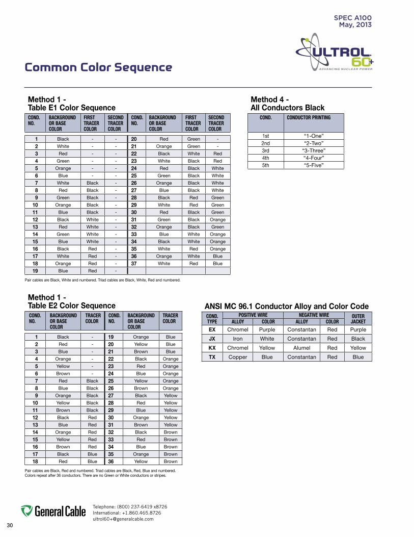
Telephone: (800) 237-6419 x8726International: [email protected]
30
ADVANCING NUCLEAR POWER
Method 1 -Table E1 Color SequenceCOND.NO.
BACKGROUNDOR BASECOLOR
FIRSTTRACERCOLOR
SECONDTRACERCOLOR
COND.NO.
BACKGROUNDOR BASECOLOR
FIRSTTRACERCOLOR
SECONDTRACERCOLOR
1 Black - - 20 Red Green -
2 White - - 21 Orange Green -
3 Red - - 22 Black White Red
4 Green - - 23 White Black Red
5 Orange - - 24 Red Black White
6 Blue - - 25 Green Black White
7 White Black - 26 Orange Black White
8 Red Black - 27 Blue Black White
9 Green Black - 28 Black Red Green
10 Orange Black - 29 White Red Green
11 Blue Black - 30 Red Black Green
12 Black White - 31 Green Black Orange
13 Red White - 32 Orange Black Green
14 Green White - 33 Blue White Orange
15 Blue White - 34 Black White Orange
16 Black Red - 35 White Red Orange
17 White Red - 36 Orange White Blue
18 Orange Red - 37 White Red Blue
19 Blue Red -
Pair cables are Black, White and numbered. Triad cables are Black, White, Red and numbered.
Common Color Sequence
Method 1 -Table E2 Color SequenceCOND.NO.
BACKGROUNDOR BASECOLOR
TRACERCOLOR
COND.NO.
BACKGROUNDOR BASECOLOR
TRACERCOLOR
1 Black - 19 Orange Blue
2 Red - 20 Yellow Blue
3 Blue - 21 Brown Blue
4 Orange - 22 Black Orange
5 Yellow - 23 Red Orange
6 Brown - 24 Blue Orange
7 Red Black 25 Yellow Orange
8 Blue Black 26 Brown Orange
9 Orange Black 27 Black Yellow
10 Yellow Black 28 Red Yellow
11 Brown Black 29 Blue Yellow
12 Black Red 30 Orange Yellow
13 Blue Red 31 Brown Yellow
14 Orange Red 32 Black Brown
15 Yellow Red 33 Red Brown
16 Brown Red 34 Blue Brown
17 Black Blue 35 Orange Brown
18 Red Blue 36 Yellow Brown
Pair cables are Black, Red and numbered. Triad cables are Black, Red, Blue and numbered. Colors repeat after 36 conductors. There are no Green or White conductors or stripes.
Method 4 -All Conductors Black
COND. CONDUCTOR PRINTING
1st “1-One”2nd “2-Two”3rd “3-Three”4th “4-Four”5th “5-Five”
ANSI MC 96.1 Conductor Alloy and Color CodeCOND. TYPE
POSITIVE WIRE NEGATIVE WIRE OUTER JACKETALLOY COLOR ALLOY COLOR
EX Chromel Purple Constantan Red Purple
JX Iron White Constantan Red Black
KX Chromel Yellow Alumel Red Yellow
TX Copper Blue Constantan Red Blue
SpEC A100May, 2013

Telephone: (800) 237-6419 x8726International: [email protected]
31
ADVANCING NUCLEAR POWERTemperature Conversion Table
SpEC A125October, 2011
Known temperature is in boldface type-Temp (°F or °C). Corresponding temperature in degrees Fahrenheit will be found in the column to the right. Corresponding temperature in degrees Centigrade will be found in the column to the left.
-5 TO -100 0 TO 100 100 TO 500
°C Temp(˚F or ˚C) °F °C Temp
(˚F or ˚C) °F °C Temp(˚F or ˚C) °F °C Temp
(˚F or ˚C) °F
-73.3-70.5-67.8-65.0-62.2-59.5-56.7-53.9-51.1-48.3-45.6-42.8-40.0-37.2-34.4-31.6-28.9-26.1-23.3-20.5
-100-95-90-85-80-75-70-65-60-55-50-45-40-35-30-25-20-15-10-5
-148-139-130-121-112-103-94-85-76-67-58-49-40-31-22-13-45
1423
-17.8-17.2-16.7-16.1-15.6-15.0-14.4-13.9-13.3-12.8-12.2-11.7-11.1-10.6-10.0-9.44-8.89-8.33-7.78-7.22-6.67-6.11-5.56-5.00-4.44-3.89-3.33-2.78-2.22-1.67-1.11-0.56
00.561.111.672.222.783.333.894.445.005.566.116.677.227.788.338.899.44
0123456789
10111213141516171819202122232425262728293031323334353637383940414243444546474849
32.033.835.637.439.241.042.844.646.448.250.051.853.655.457.259.060.862.664.466.268.069.871.673.475.277.078.880.682.484.286.087.789.691.493.295.096.898.6100.4102.2104.0105.8107.6109.4111.2113.0114.8116.6118.4120.2
10.010.611.111.712.212.813.313.914.415.015.616.116.717.217.818.318.919.420.020.621.121.722.222.823.323.924.425.025.626.126.727.227.828.328.929.430.030.631.131.732.232.833.333.934.435.035.636.136.737.237.8
5051525354555657585960616263646566676869707172737475767778798081828384858687888990919293949596979899100
122.0123.8125.6127.4129.2131.0132.8134.6136.4138.2140.0141.8143.6145.4147.2149.0150.8152.6154.4156.2158.0159.8161.6163.4165.2167.0168.8170.6172.4174.2176.0177.8179.6181.4183.2185.0186.8188.6190.4192.2194.0195.8197.6199.4201.2203.0204.8206.6208.4210.2212.0
384349546066717782889399100104110116121127132138143149154160166171177182188193199204210216221227232238243249254260
100110120130140150160170180190200210212220230240250260270280290300310320330340350360370380390400410420430440450460470480490500
212230248266284302320338356374392410413428446464482500518536554572590608626644662680698716734752770788806824842860878896914932
Interpolation Factors
°C Temp(˚F or ˚C) °F °C Temp
(˚F or ˚C) °F °C Temp(˚F or ˚C) °F
0.561.111.67
123
1.83.65.4
2.222.783.33
456
7.29.010.8
3.894.445.00
789
12.614.416.2

Telephone: (800) 237-6419 x8726International: [email protected]
32
ADVANCING NUCLEAR POWERMetric Conversion factors
SpEC A150September, 2010
To Convert From To Multiply By Inches Millimeters 25.4 Millimeters Inches 0.03937
Inches Centimeters 2.54 Centimeters Inches 0.3937Length Feet Meters 0.3048 Meters Feet 3.2808
Kilofeet (1000 feet) Kilometers 0.3048 Kilometers Kilofeet (1000 feet) 3.2808 Square Inches Square Millimeters 645.16 Square Millimeters Square Inches 0.00155
Square Inches Square Centimeters 6.4516 Square Centimeters Square Inches 0.155
Area Square Inches Circular Mils 1,273,240 Circular Mils Square Inches 7.854 x 10⁻⁷
Circular Mils Square Millimeters 5.066 x 10⁴
Square Millimeters Circular Mils 1973.51
Square Feet Square Meters 0.0929 Square Meters Square Feet 10.764 Pounds Kilograms 0.4536 Kilograms Pounds 2.2046Weight Pound/Kilofeet Kilograms/Kilometer 1.4882 Kilograms/Kilometer Pounds/Kilofeet 0.6720 Ohms/Kilofeet Ohms/Kilometer 3.2808 Ohms/Kilometer Ohms/Kilofeet 0.3048
Microfarads/Kilofeet Microfarads/Kilometer 3.2808Electrical Microfarads/Kilometer Microfarads/Kilofeet 0.3048
Insulation Resistance: Megohms—Kilofeet Megohms—Kilometer 0.3048 Megohms—Kilometer Megohms—Kilofeet 3.2808 Pounds/Square Inch Kilo Pascal* 6.895
Mechanical Kilo Pascal* Pounds/Square Inch 0.1432 Pounds (force) Newtons 4.448 * 1 Pascal = 1 Newton/square meters

Telephone: (800) 237-6419 x8726International: [email protected]
33
SpEC A185May, 2013
AWG (American Wire Gauge) to mm2
(Millimeters Squared) Conversion
AWG to mm² CONVERSION TABLE
AWG/kcmil [mm²]*
20 0.52
18 0.82
16 1.31
14 2.08
12 3.31
10 5.26
8 8.36
6 13.3
4 21.2
2 33.6
1 42.4
1/0 53.5
2/0 67.4
3/0 85.0
4/0 107
250 127
300 152
350 177
400 203
450 228
500 253
600 304
750 380
800 405
1000 507* Equivalent mm2 cross-sectional area
mm² to AWG CONVERSION TABLE
mm² [mm²] * AWG/kcmil
0.5 0.52 20
0.75 0.82 18
1.5 1.31 16
2.5 2.08 14
2.5 3.31 12
4 3.31 12
6 5.26 10
10 8.36 8
16 13.3 6
25 21.2 4
35 33.6 2
35 42.4 1
50 53.5 1/0
70 67.4 2/0
95 85.0 3/0
95 107 4/0
120 107 4/0
120 127 250
150 152 300
185 177 350
185 203 400
240 228 450
240 253 500
300 304 600
400 380 750
400 405 800
500 507 1000
Multiple AWG choices — consult responsible engineer for required ampacity
* Equivalent mm2 cross-sectional area

Telephone: (800) 237-6419 x8726International: [email protected]
34
ADVANCING NUCLEAR POWERClass B Conductors for General Wiring
SpEC B025March, 2012
Copper ConductorASTM CLASS B
COND. SIZE STRANDING NOMINAL AREA NOMINAL WEIGHT
CONCENTRIC COMPRESSED COMPACT
NOMINAL O.D. NOMINAL O.D. NOMINAL O.D.
AWG/kcmil INCHES CIRCULAR MILS mm² LBS/1000 FT¹ kg/km INCHES mm INCHES mm INCHES mm
22 7/.0096 640 0.32 1.99 2.96 0.029 0.74 — — — —
20 7/.0121 1,020 0.52 3.15 4.69 0.036 0.91 — — — —
18 7/.0152 1,620 0.82 5.10 7.59 0.046 1.17 — — — —
16 7/.0192 2,580 1.31 7.74 11.52 0.058 1.47 — — — —
14 7/.0242 4,110 2.08 12.70 18.90 0.073 1.84 0.071 1.80 — —
12 7/.0305 6,530 3.31 20.20 30.10 0.092 2.32 0.089 2.26 — —
10 7/.0385 10,380 5.26 32.10 47.80 0.116 2.95 0.113 2.87 — —
8 7/.0486 16,510 8.36 51 75.90 0.146 3.71 0.142 3.60 0.134 3.40
6 7/.0612 26,240 13.30 81.10 120.70 0.184 4.67 0.178 4.53 0.169 4.29
4 7/.0772 41,740 21.20 129 192 0.232 5.89 0.225 5.72 0.213 5.41
2 7/.0974 66,360 33.60 205 305.10 0.292 7.42 0.283 7.19 0.268 6.81
1 19/.0664 83,690 42.40 258 383.90 0.332 8.43 0.322 8.18 0.299 7.59
1/0 19/.0745 105,600 53.50 326 485.10 0.373 9.47 0.362 9.19 0.336 8.53
2/0 19/.0837 133,100 67.40 411 611.60 0.419 10.64 0.406 10.32 0.376 9.55
3/0 19/.0940 167,800 85 518 770.90 0.470 11.94 0.456 11.58 0.423 10.74
4/0 19/.1055 211,600 107 653 971.80 0.528 13.41 0.512 13.01 0.475 12.07
250 37/.0822 250,000 127 772 1148.90 0.575 14.61 0.558 14.17 0.520 13.21
300 37/.0900 300,000 152 926 1378 0.630 16.00 0.611 15.52 0.570 14.48
350 37/.0973 350,000 177 1,081 1609 0.681 17.30 0.661 16.78 0.616 15.65
400 37/.1040 400,000 203 1,235 1838 0.728 18.49 0.706 17.94 0.659 16.74
500 37/.1162 500,000 253 1,544 2298 0.813 20.65 0.789 20.03 0.736 18.69
600 61/.0992 600,000 304 1,883 2802 0.893 22.68 0.866 22.00 0.813 20.65
750 61/.1109 750,000 380 2,316 3447 0.998 25.35 0.968 24.59 0.908 23.06
1000 61/.1280 1,000,000 507 3,088 4595 1.152 29.26 1.117 28.38 1.060 26.92
Dimensions and weights are nominal; subject to industry tolerances.¹ Nominal conductor weights are applicable for Concentric Class B and Compressed Stranding per ASTM B8.

Telephone: (800) 237-6419 x8726International: [email protected]
35
ADVANCING NUCLEAR POWERClass C Conductors for General Wiring
SpEC B030February, 2011
Copper Conductor
ASTM CLASS C
SIZE STRANDING NOMINAL AREA NOMINAL DIAMETER NOMINAL WEIGHT
AWG/kcmil INCHESCIRCULAR
MILS mm2 INCHES mm LBS/KFT kg/km
22 19/.0063 640 0.32 0.031 0.79 2.34 3.48
20 19/.0080 1,020 0.52 0.038 0.97 3.71 5.52
18 19/.0092 1,620 0.82 0.044 1.12 5.00 7.40
16 19/.0117 2,580 1.31 0.056 1.42 7.97 11.86
14 19/.0147 4,110 2.08 0.070 1.80 12.70 18.90
12 19/.0185 6,530 3.31 0.089 2.24 20.20 30.10
10 19/.0234 10,380 5.26 0.112 2.85 32.05 47.80
9 19/.0262 13,090 6.63 0.126 3.20 40.40 60.10
8 19/.0295 16,510 8.37 0.143 3.63 51.00 74.40
7 19/.0331 20,820 10.50 0.162 4.11 64.30 95.70
6 19/.0372 26,240 13.30 0.184 4.67 81.00 121
5 19/.0417 33,090 16.80 0.203 5.16 102 152
4 19/.0469 41,740 21.20 0.235 5.97 129 192
3 19/.0526 52,620 26.70 0.263 6.68 163 243
2 19/.0591 66,360 33.60 0.296 7.52 205 305
1 37/.0476 83,690 42.40 0.323 8.20 258 384
1/0 37/.0534 105,600 53.50 0.362 9.20 326 485
2/0 37/.0600 133,100 67.40 0.407 10.33 411 612
3/0 37/.0673 167,800 85 0.457 11.60 518 771
4/0 37/.0756 211,600 107 0.513 13.03 653 972
250 31/.0640 250,000 127 0.558 14.17 774 1150
262.6 — — — — — — —
300 61/.0701 300,000 152 0.612 15.54 927 1380
313.1 — — — — — — —
350 61/.0757 350,000 177 0.661 16.79 1082 1610
373.7 — — — — — — —
400 61/.0810 400,000 203 0.711 18.10 1235 1838
444.4 — — — — — — —
500 61/.0905 500,000 253 0.791 20.10 1545 2299
535.3 — — — — — — —
592 — — — — — — —
600 91/.0812 600,000 304 0.893 22.70 1853 2757
646.4 — — — — — — —
750 91/.0908 750,000 380 0.999 25.40 2316 3446
777.7 — — — — — — —
1000 91/.1048 1,000,000 507 1.153 29.30 3088 4595
1111 — — — — — — —
Dimensions and weights are nominal; subject to industry tolerances.

Telephone: (800) 237-6419 x8726International: [email protected]
36
ADVANCING NUCLEAR POWER
SpEC B035February, 2011
Class h Conductors for General Wiring
Copper Conductor
ASTM CLASS H
SIZE STRANDING NOMINAL AREA NOMINAL DIAMETER NOMINAL WEIGHT
AWG/kcmil INCHESCIRCULAR
MILS mm² INCHES mm LBS/KFT kg/km
9 — — — — — — —
8 133/.0111 16,510 8.37 0.164 4.17 52 77
7 133/.0126 20,820 10.50 0.190 4.83 67 100
6 133/.0140 26,240 13.30 0.204 5.18 82 122
5 133/.0158 33,090 16.80 0.231 5.87 105 156
4 133/.0177 41,740 21.20 0.260 6.60 132 196
3 133/.0199 52,620 26.70 0.292 7.42 167 248
2 133/.0223 66,360 33.60 0.327 8.31 208 310
1 259/.0180 83,690 42.40 0.363 9.22 266 396
1/0 259/.0202 105,600 53.50 0.407 10.30 334 497
2/0 259/.0227 133,100 67.40 0.458 11.60 422 628
3/0 259/.0255 167,800 85 0.515 13.10 533 793
4/0 259/.0286 211,600 107 0.579 14.70 670 997
250 427/.0242 250,000 127 0.627 15.90 795 1183
262.6 — — — — — — —
300 427/.0265 300,000 152 0.702 17.80 953 1418
313.1 — — — — — — —
350 427/.0286 350,000 177 0.740 18.80 1110 1652
373.7 — — — — — — —
400 427/.0306 400,000 203 0.809 20.50 1270 1890
444.4 — — — — — — —
500 427/.0342 500,000 253 0.900 22.90 1590 2366
535.3 — — — — — — —
592 — — — — — — —
600 703/.0292 600,000 304 1.022 26.00 1920 2857
646.4 — — — — — — —
750 703/.0327 750,000 380 1.122 28.50 2410 3586
777.7 — — — — — — —
1000 703/.0377 1,000,000 507 1.294 32.90 3205 4769
1111 — — — — — — —
Dimensions and weights are nominal; subject to industry tolerances.

Telephone: (800) 237-6419 x8726International: [email protected]
37
ADVANCING NUCLEAR POWERClass I Conductors for General Wiring
SpEC B040March, 2012
ASTM CLASS I
SIZE STRANDING NOMINAL AREA NOMINAL DIAMETER NOMINAL WEIGHT
AWG/kcmil INCHESCIRCULAR
MILS mm2 INCHES mm LBS/KFT kg/km
10 27/.0201 10,910 5.53 0.117 2.97 33.70 50
9 — — — — — — —
8 37/.0201 14,950 7.57 0.135 3.43 46 68
7 — — — — — — —
6 61/.0201 24,640 12.50 0.174 4.42 77 114
5 91/.0201 36,760 19 0.242 6.15 116 173
4 105/.0201 42,420 21 0.262 6.60 137 204
3 126/.0201 50,500 25 0.285 7.24 167 249
2 147/.0201 60,600 31 0.307 7.80 190 283
1 224/.0201 90,900 46 0.380 9.65 287 427
1/0 273/.0201 111,100 56 0.410 10.41 351 522
2/0 323/.0201 131,300 66 0.470 11.90 407 606
3/0 456/.0201 184,200 92 0.549 13.94 594 884
4/0 551/.0201 222,600 112 0.593 14.70 696 1035
250 — — — — — — —
262.6 646/.0201 261,000 133 0.630 16 820 1220
300 — — — — — — —
313.1 777/.0201 313,900 159 0.685 17.40 987 1469
350 — — — — — — —
373.7 925/.0201 373,700 189 0.750 19 1176 1750
400 — — — — — — —
444.4 1110/.0201 448,400 225 0.820 20.80 1413 2103
500 — — — — — — —
535.3 1332/.0201 538,100 271 0.895 22.70 1697 2525
592 1480/.0201 597,900 303 0.972 24.70 1858 2765
600 — — — — — — —
646.4 1591/.0201 642,800 327 0.980 24.90 2020 3006
750 — — — — — — —
777.7 1924/.0201 777,700 394 1.075 27.30 2435 3624
1000 — — — — — — —
1111 2745/.0201 1,111,000 563 1.328 33.70 3400 5059
Dimensions and weights are nominal; subject to industry tolerances.
Copper Conductor

Telephone: (800) 237-6419 x8726International: [email protected]
38
ADVANCING NUCLEAR POWERClass K Conductors for General Wiring
SpEC B045March, 2012
Copper Conductor
ASTM CLASS K
SIZE STRANDING NOMINAL AREA NOMINAL DIAMETER NOMINAL WEIGHT
AWG/kcmil INCHESCIRCULAR
MILS mm2 INCHES mm LBS/KFT kg/km
22 — — — — — — —
20 10/.010 1,020 0.52 0.036 0.91 3.2 4.8
18 16/.010 1,620 0.82 0.046 1.20 5 7.4
16 26/.010 2,580 1.31 0.057 1.40 7.97 12
14 41/.010 4,110 2.08 0.071 1.80 12.8 19
12 65/.010 6,530 3.31 0.088 2.20 20.3 30.2
10 105/.010 10,380 5.26 0.112 2.80 33.3 49.6
9 133/.010 13,090 6.63 0.150 3.80 42.4 63.1
8 168/.010 16,510 8.37 0.164 4 53.2 80.8
7 210/.010 20,820 10.50 0.175 4.40 66.8 99.4
6 266/.010 26,240 13.30 0.198 5.00 84.2 125
5 336/.010 33,090 16.80 0.261 6.60 106 158
4 420/.010 41,740 21.20 0.249 6.30 132 196
3 532/.010 52,620 26.70 0.298 7.60 169 251
2 665/.010 66,360 33.60 0.317 8.10 211 314
1 836/.010 83,690 42.40 0.356 9 266 396
1/0 1064/.010 105,600 53.50 0.401 10 338 503
2/0 1323/.010 133,100 67.40 0.501 13 425 632
3/0 1666/.010 167,800 85 0.562 14 535 796
4/0 2107/.010 211,600 107 0.627 15.93 676 1006
250 2499/.010 250,000 127 0.688 17 802 1193
262.6 2220/.010 222,000 112 0.680 17 824 1226
300 2989/.010 300,000 152 0.753 19 960 1428
313.1 3136/.010 313,600 159 0.750 19 969 1442
350 3458/.010 350,000 177 0.818 21 1120 1667
373.7 3737/.010 373,700 189 0.790 20 1210 1800
400 3990/.010 400,000 203 0.878 22 1290 1920
444.4 — — — — — — —
500 5054/.010 500,000 253 0.990 25 1635 2433
535.3 5320/.010 532,000 270 0.950 24 1641 2442
592 — — — — — — —
600 5985/.010 600,000 340 1.125 29 1950 2902
646.4 6466/.010 646,600 328 1.040 26 1987 2957
750 7448/.010 750,000 380 1.276 32 2427 3611
777.7 — — — — — — —
1000 9975/.010 1,000,000 507 1.498 38 3250 4769
1111 — — — — — — —
Dimensions and weights are nominal; subject to industry tolerances.

Telephone: (800) 237-6419 x8726International: [email protected]
39
ADVANCING NUCLEAR POWER
How to Handle Cable Reels
.
Cradle both reel flanges between forks.
Reels can be hoisted with a shaft extended through both flanges.
Lower reels from truck using hydraulic gate, hoist or fork lift. LOWER CAREFULLY.
Always load with flanges on edge and chock and block securely.
Always load with flanges on edge and chock and block securely.
Do not lift by top flange. Cable or reel will be damaged
Use a spreader bar to prevent bending the reel flanges and mashing the cable.
Upended heavy reels will often arrive damaged. Refuse or receive subject to inspection for hidden damage.
Never allow forks to touch cable surface or reel wrap.
Never drop reels.
YES NO
Recommended Reel handling Practices
SpEC D005May, 2013

Telephone: (800) 237-6419 x8726International: [email protected]
40
ADVANCING NUCLEAR POWERRecommended Cable handling Practices
SpEC D025October, 2011
Unloading and Moving of Reels:Cable reels are never shipped upended (flat side down). Cable reels that arrive in this manner should be rejected or received only after a thorough inspection for damage.
See “Recommended Reel Handling Practices” page.
Upon receipt, a cable’s protective covering and/or lagging should be inspected for evidence of damage during shipment. If evidence of damage is found, a report should immediately be made to the carrier.
Under no circumstances should reels be dropped from the delivering vehicle to the ground.
Unloading and reel handling should be accomplished so that the equipment used does not contact the cable surface, and in the case of protective wrap, that the equipment does not contact the protective wrap.
If unloading and reel handling is accomplished by crane, either a cradle supporting the reel flanges or a shaft through the arbor hole should be used. If a fork lift is utilized, the forks must lift the reel at 90˚ to the flanges and the forks must be long enough to make complete lifting contact with both flanges. Under no circumstances should the forks come into contact with the cable surface or the protective wraps.
When a reel of cable is rolled from one point to another, care must be taken to see that there are no objects on the surface area which could contact or damage the cable surface or protective wrap.
If an inclined ramp is used for unloading, the ramp must be wide enough to contact both flanges completely. The stopping of the reels at the bottom shall be accomplished by using the reel flanges and not the surface of the cable.
Minimum Drum Diameters for Packaging Cables
Type of Cable Minimum Drum Diameter as a Multiple of Outside Diameter of Cable
1. Single and multiple conductor cable - unshielded 0-2000 V 10
2. Single and multiple conductor cable - unshielded 2400 V 12
3. Single and multiple conductor cable - wire shield (UniShield®) 5-35 kV
12
4. Single and multiple conductor cable - helically applied tape shield (Uniblend®) 5-35 kV
14
5. Single and multiple conductor cable - longitudinally applied flat tape shield (Type TC)
20
6. Single and multiple conductor cable - Interlocked Armor (Duralox®) 600 V-35 kV
14
7. Triplexed single conductors cabled together. The circumscribing overall diameter* shall be multiplied by the factor in 1 - 6 and then by the reduction factor.
.75
*Single conductor times 2.155 times
NEMA WC26 EEMAC201-2007 Binational Wire and Cable Packaging Standard

Telephone: (800) 237-6419 x8726International: [email protected]
41
ADVANCING NUCLEAR POWERRecommended Cable Storage Practices
SpEC D050May, 2013
Storage and Storage Maintenance:Finished cables have no established shelf-life. Moisture and atmospheric conditions can cause exposed conductors to oxidize and discolor. Uncovered/unsheltered cable will degrade due to exposure to direct sunlight and/or the elements. If the cables are protected, there should be no degradation of the insulation.
In general, any cable for use indoors should be stored indoors. Any cable suitable for installation outdoors is suitable for storage outdoors. Cables stored outdoors should have the ends sealed to prevent moisture ingress into the cable and should be used within two years or less.
Cables should be stored in a sheltered area. The cable conductor should not be exposed to water.
Cables with a cold temperature marking, e.g. –10˚C, –25˚C, or –40˚C, may be stored outdoors. Cables without a cold temperature marking must be stored indoors.
Cable reels must remain in the upright position. Cable reels must not be stored on their sides. Reels must not be stacked.
Cable reels should be stored with the protective covering or lagging in place. If a length of cable has been cut from the reel, the cable end should be immediately resealed to prevent the entrance of moisture. If a part length is returned to storage, the reel’s protective covering should be restored.
Wooden reels should be stored off the ground to prevent rotting. Reels should be stored on a flat, hard surface so that flanges do not sink into the earth. The weight of the reel and cable must be carried at all times by the reel flanges.
Cable reels and lagging must not be stored for an extended time period sitting in direct contact with water or dampness. Timbers or metal supports must be placed under the reel flanges to provide elevated storage of the reels away from the direct contact with water or damp soil.
Reels should be stored in an area where construction equipment, falling or flying objects or other materials will not contact the cable.
Cable should be stored in an area where chemicals or petroleum products will not be spilled or sprayed on the cable.
Cable should be stored in an area away from open fires or sources of high heat.
If the reels are relocated, they should be handled as suggested in the “Recommended Reel Handling Practices” section, and inspection made on each reel during the relocation.
If the cables are stored in a secure area and not exposed to the effects of the weather, an annual inspection should be satisfactory.
Where the reels are exposed to the weather, a bimonthly inspection should be performed to observe any sign of deterioration.
If the reels are exposed in a non-secure area, policing of the area at frequent intervals may be required depending on circumstances.
Records of delivery date, manufacturer, installation date, any extenuating circumstances, along with all test reports, should be kept on file.

Telephone: (800) 237-6419 x8726International: [email protected]
42
ADVANCING NUCLEAR POWERPre-Installation Instructions
SpEC E005April, 2010
OverviewTo ensure safety during cable installation and reliability once the cable is installed, you should confirm the following prior to installation:
• Thecableselectedisproperforyourapplication
• Thecablehasnotbeendamagedintransit or storage
Review all applicable state and national codes to verify that the cable chosen is appropriate for the job. Also, consult your local building authority.
Next, you must identify any existing cable damage and prevent any further damage from occurring. This is done through proper cable inspection, handling and storage.
Cable InspectionInspect every cable reel for damage before accepting the shipment. Be particularly alert for cable damage if:
• Areelislayingflatonitsside
• Severalreelsarestacked
• Otherfreightisstackedonareel
• Nailshavebeendrivenintoreelflangesto secure shipping blocks
• Areelflangeisdamaged
• Acablecoveringisremoved,stainedordamaged
• Acableendsealisremovedor damaged
• Areelhasbeendropped (hidden damage likely)
Cabling HandlingRemove all nails and staples from the reel flanges before moving a reel, and avoid all objects that could crush, gouge or impact the cable when moving. NEVER use the cable as a means to move a reel.
When unreeling, observe recommended bending radii, use swivels to prevent twisting and avoid overruns.
Pre-Installation

Telephone: (800) 237-6419 x8726International: [email protected]
43
ADVANCING NUCLEAR POWERInstallation – Overview and Checklist
SpEC E025January, 2011
OverviewMost cables are subjected to more mechanical stress during installation than they ever experience in actual operation. Needless to say, handling and pulling your cable according to manufacturer’s recom-mendations is extremely important.
There are six main considerations in any cable installation:
• Ambienttemperature
• Equipment
• Conduitfill
• Mechanicalfitinraceway
• Physicallimitations
• Knowledgeableinstallers
For more information, reference IEEE 1185 Recommended Practices for Cable Installations in Generating Stations and Industrial Facilities.
Installation TemperatureLow temperatures are a cause for concern when installing cable. Cable should not be installed when temperatures are less than the cold bend temperature rating of the cable product plus 15°C (i.e., minimum installation temperature = cold bend temperature rating + 15°C). The cold bend temperature rating is indicated on the catalog Spec sheet.
Prior to performing a low temperature (less than 10°F or -12˚C) cable installation, cable should be stored for a minimum of 24 hours at a temperature of 55°F (13˚C) or higher.
Cable should be pulled more slowly and trained in place the same day it is removed from storage. Do not impact, drop, kink or bend cable sharply in low temperatures.
EquipmentThe proper use of appropriate equipment is crucial to a successful cable installation. The equipment needed for most installa-tions is detailed in the following checklist:
0-1/5/10 kip dynamometer basket grip pullers cable cutter cable end seals cable pulling lubricant cable tray bend sheaves cable tray rollers capstan-type puller diameter tape duct cleaning mandrels electric safety blankets and clamps extension cords and GFCI protection fish tape or string blower/vacuum floodlights gang rollers: with at least 4 ft.
effective radius gloves guide-in flexible tubing (elephant trunks) hand winches (come-a-long) HI-POT tester lint-free rags make-up air blower & hose manhole edge sheave measuring tape personal protection equipment (PPE) plywood sheets portable electric generator pre-lubing devices pulling rope pump, diaphragm radios or telephones reel arbor reel brakes reel jacks several wire rope slings of various
lengths shackles/clevis short ropes for temp tie-offs swivels warning flags, signs
Installation

Telephone: (800) 237-6419 x8726International: [email protected]
44
ADVANCING NUCLEAR POWERInstallation – feed-In Setups
SpEC E050April, 2010
The following diagrams illustrate various cable feed-in setups:
Cable Feed-In Setups
The feed-in setup should unreel the cable with a natural curvature (Figure 1) as opposed to a reverse “S” curvature (Figure 2).
Reels on truck
Apply lube here
Guide-in tube
Setup for duct close to floor
Setup for overhead, into tray
IMPROPER
Figure 2
PROPER
Figure 1

Telephone: (800) 237-6419 x8726International: [email protected]
45
ADVANCING NUCLEAR POWERInstallation – feed-In Setups
SpEC E050April, 2010
Remember to use the radius of the surface over which the cable is bent, not the outside flange diameter of the pulley. A “10 inch” cable sheave typically has a 10 inch outside flange diameter with a 6 inch inside diameter that provides an inside (bending) radius of 3 inches.
Single sheaves should only be used for GUIDING cables. Arrange multiple blocks to maintain bending radii whenever cable changes direction or elevation.
For pulling around bends, use conveyor sheave assemblies of the appropriate radius series.
The pulleys must be positioned to ensure that the effective curvature is smooth and changes direction or elevation evenly at each pulley. Never allow a polygon curvature to occur (Figure 3).
The fit of a pulley around the cable is also important when pulling heavy weights (i.e. pulleys at the top of a vertical drop).
Cable Feed-In Setups (continued)
Single Sheave
Sheave Assembly
NEVER ALLOW
Figure 3
Radius

Telephone: (800) 237-6419 x8726International: [email protected]
46
ADVANCING NUCLEAR POWER
Installation – Conductor MaximumPulling TensionsMulti-Conductor Cables Having Equal-Sized Conductors; In parallel or as Multiplexed Assemblies
SpEC E075October, 2012
AWG/kcmil
MAXIMUM ALLOWABLE PULLING TENSION (LBS)
NUMBER OF CONDUCTORS
1 2 3 4 5 6
181614
132033
264066
396099
4165105
5281132
6297158
12108
5283132
104166264
157249396
167266423
209332528
251399634
642
210334531
4206681062
63010021593
67210691699
84013362124
100816032548
11/02/0
6708451065
133916902130
200925343194
214227033407
267833794259
321440555111
3/04/0250
134216932000
268533864000
402750786000
429654176400
537067718000
644481259600
350500750
280040006000
5600800010000
84001000010000
89601000010000
100001000010000
100001000010000
1000 8000 10000 10000 10000 10000 10000
The maximum allowable pulling tensions are for direct attachment to the conductor. T = 0.008 x cmil x n, if n ≤ 3T = 0.008 x cmil x n x 0.8, if n > 3
When more than two conductors are pulled in parallel in an installation containing bends, the maximun allowable pulling tension is limited to the two conductor column, regardless of the number of conductors that are being pulled.

Telephone: (800) 237-6419 x8726International: [email protected]
47
ADVANCING NUCLEAR POWER
SpEC E075October, 2012
NUMBER OF CONDUCTORS
MAXIMUM ALLOWABLE PULLING TENSION (LBS)
CONDUCTOR SIZE (AWG/kcmil)
18 16 14 12 10
234
263941
406065
6699105
104157167
166249266
567
526273
8197113
132158184
209251293
332399465
8910
8393104
129145161
210237263
334376418
531598664
121415
124145156
194226242
316368395
502585627
797930996
161819
166187197
258290306
421473500
669752794
100010001000
202224
207228249
323355387
526549631
8369191000
100010001000
253037
259311383
403484596
658789974
100010001000
100010001000
The maximum allowable pulling tensions are for multi-conductor cables pulled into a raceway or cable tray using a basket grip or similar device secured directly to the cable jacket. It is recommended that a combination of basket grips and pulling eyes be used whenever possible.T = 0.008 x cmil x n, if n ≤ 3T = 0.008 x cmil x n x 0.8, if n > 3
Installation – Conductor MaximumPulling TensionsMulti-Conductor Cables Having Equal-Sized Conductors, Without Subassemblies

Telephone: (800) 237-6419 x8726International: [email protected]
48
ADVANCING NUCLEAR POWER
SpEC E100April, 2010
Installation – Training and Bending Limitations
Physical Limitations Training and Bending
Overview
Training is the positioning of cable when it is not under tension. Bending is the positioning of cable when it is under tension. When installing cable, the object is to limit the mechanical forces so that the cable’s physical and electrical characteristics are maintained for the expected service life. Depending on the pullingtension, a pulling bend radius value larger than the minimum may be required to limit the sidewall pressure. Bends in conductors, multi-conductor cables or assemblies of conductors shall be made so that the cable will not be damaged.
A nonshielded cable can tolerate a sharper bend than a shielded cable. This is especially true for cables having helically applied metallic shielding tapes which, when bent too sharply, can separate or buckle and cut into the insulation. Rememberthat offsets are bends.
The problem is compounded by the fact that most tapes are under jackets that conceal such damage. The extruded polymers used for insulation shields have sufficientconductivity and coverage initially to pass acceptance testing, then fail prematurely due to corona at the shield/insulationinterface.
MINIMUM BENDING RADIUS IN ACCORDANCE WITH NATIONAL ELECTRIC CODE
Voltage Conductors Shielding Cable Types Minimum Bending Radius as a Multipleof Conductor/Assembly Diameter
600 V Single Nonshielded All 5X
601- 2000 V All 8X
600 Vor
2000 V
Multi-conductor
orMultiplexed
Nonshielded TC or TC-ER1 in. (25 mm)
or less
Over 1 in.to 2 in.
(>25 mm to 50 mm)
Over 2 in.(>50 mm)
4X 5X 6X
MC3 7X
Shielded
All 12X
TC or TC-ER 12X
MC 12X/7X1
Over2000 V
SingleNonshielded
MV 8X
MC3 7X
Shielded MC and MV 12X2
Multi-conductor orMultiplexed
Nonshielded MC and MV 8X
Shielded MC and MV 12X/7X1,2
1 12 times the diameter of an individual shielded conductor or 7 times the overall cable diameter, whichever is greater.2 Since UniShield® is a unique construction, there are no applicable values for the bending radius in the NEC. However, General
Cable recommends 8 times for single conductors, and for multiplexed or multi-conductor cables, it is 8 times the diameter of the individual conductors or 5 times the overall diameter, whichever is greater, in accordance with ANSI/ICEA S-93-639 5-46 kV Shielded Power Cable for Use in the Transmission and Distribution of Electric Energy.
3 Per 330.24B Interlocked-Type Armor or Continuously Corrugated Metallic Sheath.

Telephone: (800) 237-6419 x8726International: [email protected]
49
ADVANCING NUCLEAR POWER
SpEC E130May, 2013
Installation – Maximum Sidewall Pressure
Overview
Sidewall bearing pressure (SWBP),or sidewall loading, is the radial force exerted on a cable being pulled around a conduit bend or sheave. ExcessiveSWBPcancrushacableandis,therefore,one of the most restrictive factors in installations having bends and requiring highpullingtensions.SWBPisreducedby increasing the radius of bends.
The maximum tension that can safely be applied to the cable during installation can be calculated using the maximum SWBP for the cable and the radius ofthe bend it is traversing.
For example, a cable having a maximum SWBPof300lb/ftthatisbeingpulledaround a bend having a radius of 2 feet shouldhavenomorethan300lbs/ftx2ftor600lbstensionappliedtoitasthecable exits the bend.
Compatible Cable pulling Lubricants:
AmericanPolywaterCorp. Polywater®J Polywater®LZ
CABLE TyPE SWBP (LBS/FT)
300 V Nonshielded, 300 V and 600 V Shielded Control & Instrumentation 500
600 V Nonshielded Control & Instrumentation 500
600 V and 2400 V Nonshielded Power 1000
5 kV-35 kV Shielded Power 1000
Interlocked Armored Cable (all voltage) 300
CCW® MC-HL Armored Cable 500
Sidewall Load
Tension
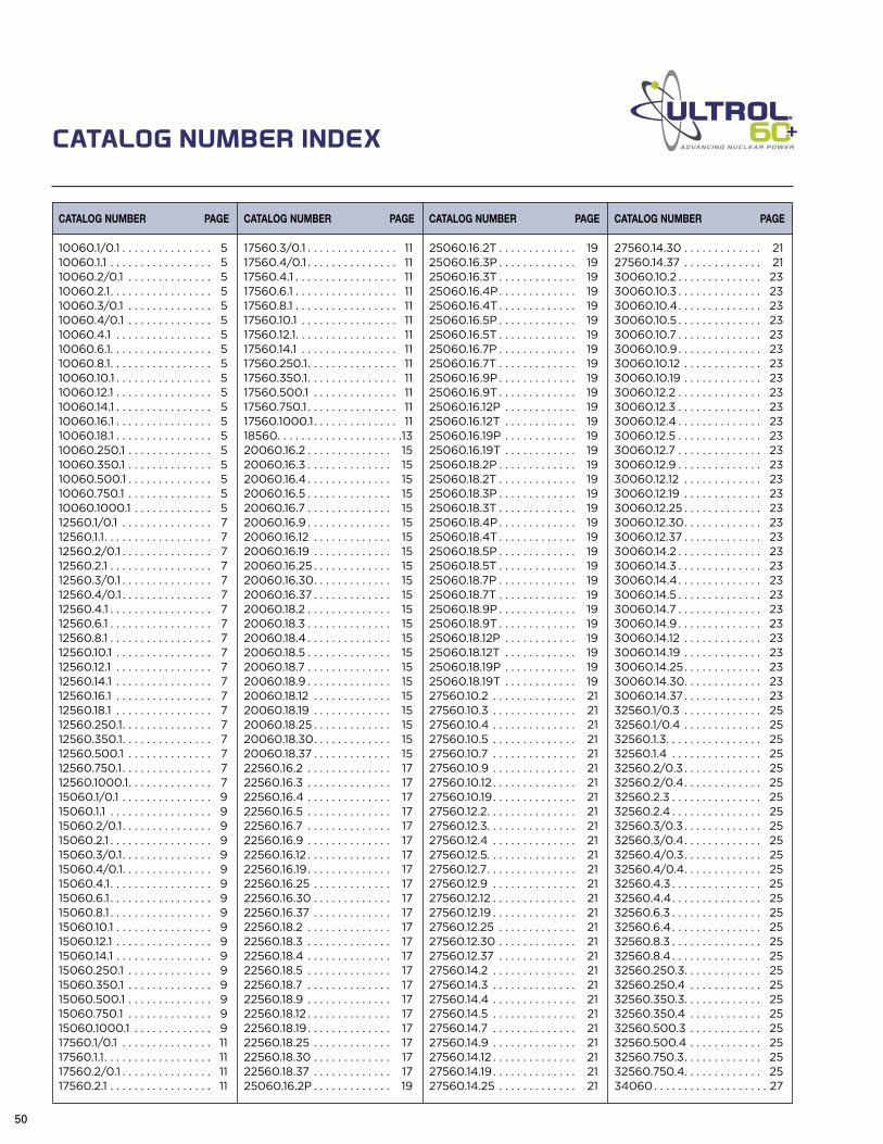
50
ADVANCING NUCLEAR POWER
10060.1/0.1 . . . . . . . . . . . . . . . 510060.1.1 . . . . . . . . . . . . . . . . . 510060.2/0.1 . . . . . . . . . . . . . . 510060.2.1. . . . . . . . . . . . . . . . . 510060.3/0.1 . . . . . . . . . . . . . . 510060.4/0.1 . . . . . . . . . . . . . . 510060.4.1 . . . . . . . . . . . . . . . . 510060.6.1. . . . . . . . . . . . . . . . . 510060.8.1. . . . . . . . . . . . . . . . . 510060.10.1 . . . . . . . . . . . . . . . . 510060.12.1 . . . . . . . . . . . . . . . . 510060.14.1 . . . . . . . . . . . . . . . . 510060.16.1 . . . . . . . . . . . . . . . . 510060.18.1 . . . . . . . . . . . . . . . . 510060.250.1 . . . . . . . . . . . . . . 510060.350.1 . . . . . . . . . . . . . . 510060.500.1 . . . . . . . . . . . . . . 510060.750.1 . . . . . . . . . . . . . . 510060.1000.1 . . . . . . . . . . . . . 512560.1/0.1 . . . . . . . . . . . . . . . 712560.1.1. . . . . . . . . . . . . . . . . . 712560.2/0.1 . . . . . . . . . . . . . . . 712560.2.1 . . . . . . . . . . . . . . . . . 712560.3/0.1 . . . . . . . . . . . . . . . 712560.4/0.1 . . . . . . . . . . . . . . . 712560.4.1 . . . . . . . . . . . . . . . . . 712560.6.1 . . . . . . . . . . . . . . . . . 712560.8.1 . . . . . . . . . . . . . . . . . 712560.10.1 . . . . . . . . . . . . . . . . 712560.12.1 . . . . . . . . . . . . . . . . 712560.14.1 . . . . . . . . . . . . . . . . 712560.16.1 . . . . . . . . . . . . . . . . 712560.18.1 . . . . . . . . . . . . . . . . 712560.250.1. . . . . . . . . . . . . . . 712560.350.1. . . . . . . . . . . . . . . 712560.500.1 . . . . . . . . . . . . . . 712560.750.1. . . . . . . . . . . . . . . 712560.1000.1. . . . . . . . . . . . . . 715060.1/0.1 . . . . . . . . . . . . . . . 915060.1.1 . . . . . . . . . . . . . . . . . 915060.2/0.1. . . . . . . . . . . . . . . 915060.2.1 . . . . . . . . . . . . . . . . . 915060.3/0.1. . . . . . . . . . . . . . . 915060.4/0.1. . . . . . . . . . . . . . . 915060.4.1 . . . . . . . . . . . . . . . . . 915060.6.1 . . . . . . . . . . . . . . . . . 915060.8.1 . . . . . . . . . . . . . . . . . 915060.10.1 . . . . . . . . . . . . . . . . 915060.12.1 . . . . . . . . . . . . . . . . 915060.14.1 . . . . . . . . . . . . . . . . 915060.250.1 . . . . . . . . . . . . . . 915060.350.1 . . . . . . . . . . . . . . 915060.500.1 . . . . . . . . . . . . . . 915060.750.1 . . . . . . . . . . . . . . 915060.1000.1 . . . . . . . . . . . . . 917560.1/0.1 . . . . . . . . . . . . . . . 1117560.1.1. . . . . . . . . . . . . . . . . . 1117560.2/0.1 . . . . . . . . . . . . . . . 1117560.2.1 . . . . . . . . . . . . . . . . . 11
17560.3/0.1 . . . . . . . . . . . . . . . 1117560.4/0.1 . . . . . . . . . . . . . . . 1117560.4.1 . . . . . . . . . . . . . . . . . 1117560.6.1 . . . . . . . . . . . . . . . . . 1117560.8.1 . . . . . . . . . . . . . . . . . 1117560.10.1 . . . . . . . . . . . . . . . . 1117560.12.1. . . . . . . . . . . . . . . . . 1117560.14.1 . . . . . . . . . . . . . . . . 1117560.250.1. . . . . . . . . . . . . . . 1117560.350.1. . . . . . . . . . . . . . . 1117560.500.1 . . . . . . . . . . . . . . 1117560.750.1 . . . . . . . . . . . . . . . 1117560.1000.1. . . . . . . . . . . . . . 1118560. . . . . . . . . . . . . . . . . . . . .1320060.16.2 . . . . . . . . . . . . . . 1520060.16.3 . . . . . . . . . . . . . . 1520060.16.4 . . . . . . . . . . . . . . 1520060.16.5 . . . . . . . . . . . . . . 1520060.16.7 . . . . . . . . . . . . . . 1520060.16.9 . . . . . . . . . . . . . . 1520060.16.12 . . . . . . . . . . . . . 1520060.16.19 . . . . . . . . . . . . . 1520060.16.25 . . . . . . . . . . . . . 1520060.16.30. . . . . . . . . . . . . 1520060.16.37 . . . . . . . . . . . . . 1520060.18.2 . . . . . . . . . . . . . . 1520060.18.3 . . . . . . . . . . . . . . 1520060.18.4 . . . . . . . . . . . . . . 1520060.18.5 . . . . . . . . . . . . . . 1520060.18.7 . . . . . . . . . . . . . . 1520060.18.9 . . . . . . . . . . . . . . 1520060.18.12 . . . . . . . . . . . . . 1520060.18.19 . . . . . . . . . . . . . 1520060.18.25 . . . . . . . . . . . . . 1520060.18.30. . . . . . . . . . . . . 1520060.18.37 . . . . . . . . . . . . . 1522560.16.2 . . . . . . . . . . . . . . 1722560.16.3 . . . . . . . . . . . . . . 1722560.16.4 . . . . . . . . . . . . . . 1722560.16.5 . . . . . . . . . . . . . . 1722560.16.7 . . . . . . . . . . . . . . 1722560.16.9 . . . . . . . . . . . . . . 1722560.16.12 . . . . . . . . . . . . . . 1722560.16.19 . . . . . . . . . . . . . . 1722560.16.25 . . . . . . . . . . . . . 1722560.16.30 . . . . . . . . . . . . . 1722560.16.37 . . . . . . . . . . . . . 1722560.18.2 . . . . . . . . . . . . . . 1722560.18.3 . . . . . . . . . . . . . . 1722560.18.4 . . . . . . . . . . . . . . 1722560.18.5 . . . . . . . . . . . . . . 1722560.18.7 . . . . . . . . . . . . . . 1722560.18.9 . . . . . . . . . . . . . . 1722560.18.12 . . . . . . . . . . . . . . 1722560.18.19 . . . . . . . . . . . . . . 1722560.18.25 . . . . . . . . . . . . . 1722560.18.30 . . . . . . . . . . . . . 1722560.18.37 . . . . . . . . . . . . . 1725060.16.2P . . . . . . . . . . . . . 19
25060.16.2T . . . . . . . . . . . . . 1925060.16.3P . . . . . . . . . . . . . 1925060.16.3T . . . . . . . . . . . . . 1925060.16.4P . . . . . . . . . . . . . 1925060.16.4T . . . . . . . . . . . . . 1925060.16.5P . . . . . . . . . . . . . 1925060.16.5T . . . . . . . . . . . . . 1925060.16.7P . . . . . . . . . . . . . 1925060.16.7T . . . . . . . . . . . . . 1925060.16.9P . . . . . . . . . . . . . 1925060.16.9T . . . . . . . . . . . . . 1925060.16.12P . . . . . . . . . . . . 1925060.16.12T . . . . . . . . . . . . 1925060.16.19P . . . . . . . . . . . . 1925060.16.19T . . . . . . . . . . . . 1925060.18.2P . . . . . . . . . . . . . 1925060.18.2T . . . . . . . . . . . . . 1925060.18.3P . . . . . . . . . . . . . 1925060.18.3T . . . . . . . . . . . . . 1925060.18.4P . . . . . . . . . . . . . 1925060.18.4T . . . . . . . . . . . . . 1925060.18.5P . . . . . . . . . . . . . 1925060.18.5T . . . . . . . . . . . . . 1925060.18.7P . . . . . . . . . . . . . 1925060.18.7T . . . . . . . . . . . . . 1925060.18.9P . . . . . . . . . . . . . 1925060.18.9T . . . . . . . . . . . . . 1925060.18.12P . . . . . . . . . . . . 1925060.18.12T . . . . . . . . . . . . 1925060.18.19P . . . . . . . . . . . . 1925060.18.19T . . . . . . . . . . . . 1927560.10.2 . . . . . . . . . . . . . . 2127560.10.3 . . . . . . . . . . . . . . 2127560.10.4 . . . . . . . . . . . . . . 2127560.10.5 . . . . . . . . . . . . . . 2127560.10.7 . . . . . . . . . . . . . . 2127560.10.9 . . . . . . . . . . . . . . 2127560.10.12 . . . . . . . . . . . . . . 2127560.10.19 . . . . . . . . . . . . . . 2127560.12.2. . . . . . . . . . . . . . . 2127560.12.3. . . . . . . . . . . . . . . 2127560.12.4 . . . . . . . . . . . . . . 2127560.12.5. . . . . . . . . . . . . . . 2127560.12.7. . . . . . . . . . . . . . . 2127560.12.9 . . . . . . . . . . . . . . 2127560.12.12 . . . . . . . . . . . . . . 2127560.12.19 . . . . . . . . . . . . . . 2127560.12.25 . . . . . . . . . . . . . 2127560.12.30 . . . . . . . . . . . . . 2127560.12.37 . . . . . . . . . . . . . 2127560.14.2 . . . . . . . . . . . . . . 2127560.14.3 . . . . . . . . . . . . . . 2127560.14.4 . . . . . . . . . . . . . . 2127560.14.5 . . . . . . . . . . . . . . 2127560.14.7 . . . . . . . . . . . . . . 2127560.14.9 . . . . . . . . . . . . . . 2127560.14.12 . . . . . . . . . . . . . . 2127560.14.19 . . . . . . . . . . . . . . 2127560.14.25 . . . . . . . . . . . . . 21
27560.14.30 . . . . . . . . . . . . . 2127560.14.37 . . . . . . . . . . . . . 2130060.10.2 . . . . . . . . . . . . . . 2330060.10.3 . . . . . . . . . . . . . . 2330060.10.4 . . . . . . . . . . . . . . 2330060.10.5 . . . . . . . . . . . . . . 2330060.10.7 . . . . . . . . . . . . . . 2330060.10.9 . . . . . . . . . . . . . . 2330060.10.12 . . . . . . . . . . . . . 2330060.10.19 . . . . . . . . . . . . . 2330060.12.2 . . . . . . . . . . . . . . 2330060.12.3 . . . . . . . . . . . . . . 2330060.12.4 . . . . . . . . . . . . . . 2330060.12.5 . . . . . . . . . . . . . . 2330060.12.7 . . . . . . . . . . . . . . 2330060.12.9 . . . . . . . . . . . . . . 2330060.12.12 . . . . . . . . . . . . . 2330060.12.19 . . . . . . . . . . . . . 2330060.12.25 . . . . . . . . . . . . . 2330060.12.30. . . . . . . . . . . . . 2330060.12.37 . . . . . . . . . . . . . 2330060.14.2 . . . . . . . . . . . . . . 2330060.14.3 . . . . . . . . . . . . . . 2330060.14.4 . . . . . . . . . . . . . . 2330060.14.5 . . . . . . . . . . . . . . 2330060.14.7 . . . . . . . . . . . . . . 2330060.14.9 . . . . . . . . . . . . . . 2330060.14.12 . . . . . . . . . . . . . 2330060.14.19 . . . . . . . . . . . . . 2330060.14.25 . . . . . . . . . . . . . 2330060.14.30. . . . . . . . . . . . . 2330060.14.37 . . . . . . . . . . . . . 2332560.1/0.3 . . . . . . . . . . . . . 2532560.1/0.4 . . . . . . . . . . . . . 2532560.1.3. . . . . . . . . . . . . . . . 2532560.1.4 . . . . . . . . . . . . . . . 2532560.2/0.3 . . . . . . . . . . . . . 2532560.2/0.4. . . . . . . . . . . . . 2532560.2.3 . . . . . . . . . . . . . . . 2532560.2.4 . . . . . . . . . . . . . . . 2532560.3/0.3 . . . . . . . . . . . . . 2532560.3/0.4. . . . . . . . . . . . . 2532560.4/0.3 . . . . . . . . . . . . . 2532560.4/0.4. . . . . . . . . . . . . 2532560.4.3 . . . . . . . . . . . . . . . 2532560.4.4 . . . . . . . . . . . . . . . 2532560.6.3 . . . . . . . . . . . . . . . 2532560.6.4 . . . . . . . . . . . . . . . 2532560.8.3 . . . . . . . . . . . . . . . 2532560.8.4 . . . . . . . . . . . . . . . 2532560.250.3. . . . . . . . . . . . . 2532560.250.4 . . . . . . . . . . . . 2532560.350.3. . . . . . . . . . . . . 2532560.350.4 . . . . . . . . . . . . 2532560.500.3 . . . . . . . . . . . . 2532560.500.4 . . . . . . . . . . . . 2532560.750.3. . . . . . . . . . . . . 2532560.750.4. . . . . . . . . . . . . 2534060 . . . . . . . . . . . . . . . . . . . 27
CATALOG NUMBER INDEX
CATALOG NUMBER PAGE CATALOG NUMBER PAGE CATALOG NUMBER PAGE CATALOG NUMBER PAGE


Meeting the needs ofnuclear power plantsTODAY AND INTOTHE FUTUREThe nuclear power industry demands solutions that deliver
high safety performance without fail and provide sustained
reliability under rigorous conditions.
Building upon nearly 40 years of nuclear experience,
General Cable has combined advanced materials with
manufacturing expertise to produce ULTROL® 60+
Class 1E nuclear-qualified cables.
Third-party tested to meet Generation III
reactor requirements, ULTROL® 60+ cables
exceed stringent industry standards
and specifications to provide
a 60-year-plus service life to
optimize nuclear power plant
operations TODAY AND INTO THE FUTURE.
[email protected]+1.860.465.8726

A commitment to achieving industry-leading standards and responding proactively to environmental global issues.
General Cable serves customers through a global network of 57 manufacturing facilities in 26 countries and sales representatives and distribution centers worldwide. The Company is solely dedicated to the production of high-quality energy, industrial, specialty and communications wire and cable products. In addition to its breadth of product line and strong brand recognition, the Company offers competitive strengths in such areas as technology, manufacturing, distribution and logistics, and sales and customer service. This combination enables General Cable to better serve its customers as they expand into new geographic markets.
Global Reach
GENERAL CABLE and ULTROL 60+ are trademarks of General Cable Technologies Corporation.©2013. General Cable Technologies Corporation. Highland Heights, KY 41076 All rights reserved. Printed in USA.
Form No. INS-0146-0513 43618
Corporate Headquarters4 Tesseneer DriveHighland Heights, Kentucky 41076-9753U.S.A.www.generalcable.com
For more information, contact:General Cable 1600 West Main StreetWillimantic, Connecticut [email protected]
Telephone (800) 237-6419 x8726
International Telephone +1 860 465 8726
ULTR
OL® 60+
—A
dvancing Nuclear P
ower through Cable Solutions