today‘s ideas – tomorrow‘s technologies in injection moulding · pdf file1...
TRANSCRIPT
1
EN
Today‘s Ideas – Tomorrow‘s Technologies in Injection Moulding
PLA
STI
CS
PR
OC
ES
ING
-A
AC
HIN
STI
TUTE
OF
SINTEF Technical Seminar for the Injection Moulding Industry20/21. April 2010, Oslo
Dipl.-Ing. A. NeußInstitute of Plastics Processing at RWTH Aachen University (IKV)
EN
The Institute of Plastics ProcessingInstitut für Kunststoffverarbeitung (IKV)
Founded in 1950, supported by a Sponsors' Society
PLA
STI
CS
PR
OC
ES
ING
-A
AC
H Associated with the RWTH Aachen University
Sponsors' Society with 257 members(one third foreign companies)
• raw material producers• machine manufacturers• plastics processors• research institutes• associations
INS
TITU
TE O
F
Staff of IKV : • 70 scientific employees• 55 employees in laboratories, workshops and administration• 220 student workers
(As of August 2009)

2
EN
IKV-Locations in Aachen P
LAS
TIC
S P
RO
CE
SIN
G -
AA
CH
Pontstraße 49-55Management and Executive Board
Seffenter Weg 201Composites
INS
TITU
TE O
F gInjection MouldingPUR-Technology
Training/Skilled Crafts
pExtrusion and Further ProcessingPart Design/Materials Technology
Centre for Analysis and Testing of Plastics
EN
Key features of the IKV research programme
THERMOPLASTICS, THERMOSETS, ELASTOMERS, COMPOSITES, SPECIAL MATERIALS
INJECTION MOULDING, EXTRUSION, BLOW MOULDING, COMPRESSION MOULDING, SPECIAL PROCESSES
PLA
STI
CS
PR
OC
ES
ING
-A
AC
H
PRODUCTREQUIRE-
MENTS
material data,materialmodels
CAD, CAE,design rules
CAD, CAE,design rules
productionplanning, PPS,
machineselection
SPC,statistic
experimentaldesign
materialselection
productlayout
and design
layout ofmoulds, dies
and machines
productionanalysis ofcomplex
interconnectedprocesses
qualityassurance
mould ormeasuring,controlling t ti
PRODUCT
INS
TITU
TE O
F
ENVIRONMENTAL PROTECTION, RECYCLING
PRODUCTION PLANNING, PLANT ORGANISATION
materialinnovations
productprototype
mould ordie / machine
prototype, CAM
controlling,adjusting and
optimisation ofprocess values
testing sensorsystems

3
EN
Injection Moulding Department
• special IM processes• process combinations• special materials
• process simulation• inner part properties• integrative simulation
Process Technology Simulation
PLA
STI
CS
PR
OC
ES
ING
-A
AC
H • key technologies • special IM processes
• temp. control concepts• process control• special IM processes• Rapid Prototyping/Tooling
Mould Technology Company organisation
Polyurethane Technology
• benchmarking• intercompany comparison• technical consulting• process analysis
Machine Technology
INS
TITU
TE O
F y gy• processing of rigid and flexible foams
• mould technology• reinforced polyurethane
• drive concepts• IM of micro parts• IM of foamed parts• water injection technique
gy
EN
Process TechnologySpecial Injection Moulding Processes
• gas injection technique• water injection technique
Multi-Component Injection Moulding Fluid Injection Technique (FIT)• overmoulding• sandwich moulding
PLA
STI
CS
PR
OC
ES
ING
-A
AC
H
Foam Injection Moulding (FIM) Back Injection Technique • process development• process analysis
• back IM• back I-CM
j• projectile injec. technique• process analysis• selection of material• injector technique and -design
g• hybrid technique• bond strength• process combination
2C-tensile test bar two-layer media duct
INS
TITU
TE O
F process analysis• selection of material• part- and mould design• CESP
back I CM• back FIM• process analysis• high-value decor materials
structural foam high-value decor materials
4
EN
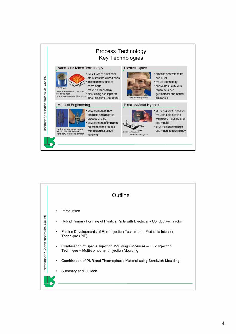
Process TechnologyKey Technologies
• process analysis of IM and I-CM
Nano- and Micro-Technology Plastics Optics• IM & I-CM of functional structures/structured parts
PLA
STI
CS
PR
OC
ES
ING
-A
AC
H
Medical Engineering Plastics/Metal-Hybrids• development of new products and adapted
• combination of injection moulding die casting
• mould technology• analysing quality with regard to inner, geometrical and optical properties
• injection moulding of micro parts
• machine technology• plasticising concepts for small amounts of plastics
mould insert with micro structureleft: mould insertright: measurement by Microglider
lens made of plastics
∅ 55 mm
INS
TITU
TE O
F products and adapted process chains
• development of implants: resorbable and loaded with biological active additives
moulding die casting within one machine and one mould
• development of mould and machine technology
cardiac septum closure-systemleft: old, Nitinol-meshworkright: new, absorbable polymer plastics/metal-hybrids
source: LANXESS AG
EN
Outline
• Introduction
PLA
STI
CS
PR
OC
ES
ING
-A
AC
H • Hybrid Primary Forming of Plastics Parts with Electrically Conductive Tracks
• Further Developments of Fluid Injection Technique – Projectile Injection Technique (PIT)
• Combination of Special Injection Moulding Processes – Fluid Injection Technique + Multi-component Injection Moulding
INS
TITU
TE O
F
• Combination of PUR and Thermoplastic Material using Sandwich Moulding
• Summary and Outlook

5
EN
Introduction
Fact• The standards of parts in terms of design
and functionality as well as demands for
Micro Technology by Injection Moulding
PLA
STI
CS
PR
OC
ES
ING
-A
AC
H
Current Situation • Special injection moulding processes are
gaining importance:more than 100 special processes!
economical, resource efficient productions often cannot be fulfilled by conventional materials and manufacturing methods.
Hollow Parts by Injection Moulding
micro parts nano- & micro structures
INS
TITU
TE O
F Multicomponent IM, Fluid Injection Technique, Backmoulding, Foaming, Insert-, Outsert- and Hybrid Technique etc.
Magnesiumdruckgussteil
Zinkdruckgussteil
[PME fluidtec GmbH, Röchling Automotive]
EN
General Trends in Manufacturing Technologies
General Trends• Demand for increased value added• Limits between different material classes and
door trim panel
PLA
STI
CS
PR
OC
ES
ING
-A
AC
H manufacturing methods have been shifted increasingly.
• Result: hybridisation of production technologiesHybrid products
Combination of different materialsin one partExample: multi-component technology; insert-, outsert-technology
H b id
INS
TITU
TE O
F Hybrid processesCombination of (special-)processes in order to produce assembly groups of different material components under reduction of the process chain.Examples: Skinform®, Dolphin®, Exjection®
plastic/metall-frontend
[BASF SE, KraussMaffei Technologies GmbH, LANXESS AG]
6
EN
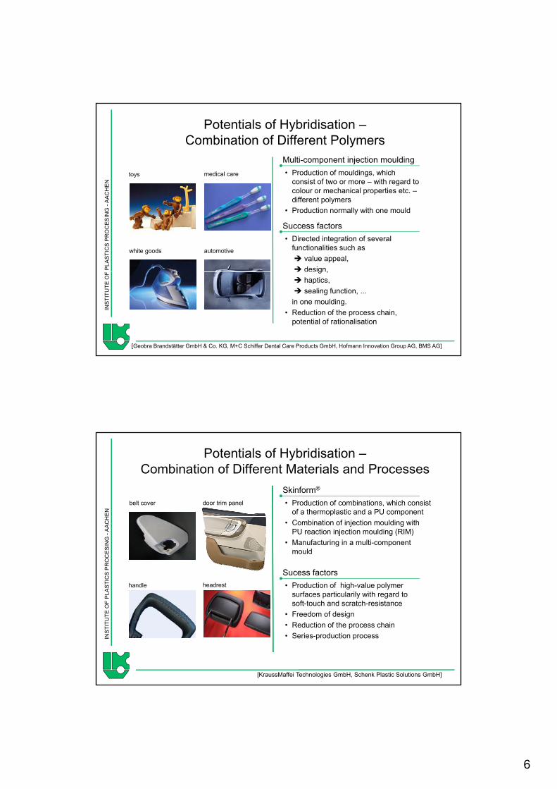
Potentials of Hybridisation –Combination of Different Polymers
Multi-component injection moulding• Production of mouldings, which
consist of two or more – with regard to toys medical care
PLA
STI
CS
PR
OC
ES
ING
-A
AC
H
Success factors• Directed integration of several
functionalities such asvalue appeal,design,
colour or mechanical properties etc. –different polymers
• Production normally with one mould
automotivewhite goods
INS
TITU
TE O
F g ,haptics,sealing function, ...
in one moulding.• Reduction of the process chain,
potential of rationalisation
[Geobra Brandstätter GmbH & Co. KG, M+C Schiffer Dental Care Products GmbH, Hofmann Innovation Group AG, BMS AG]
EN
Potentials of Hybridisation –Combination of Different Materials and Processes
Skinform®
• Production of combinations, which consist of a thermoplastic and a PU component
door trim panelbelt cover
PLA
STI
CS
PR
OC
ES
ING
-A
AC
H
Sucess factors• Production of high-value polymer
surfaces particularily with regard to ft t h d t h i t
• Combination of injection moulding with PU reaction injection moulding (RIM)
• Manufacturing in a multi-component mould
handle headrest
INS
TITU
TE O
F soft-touch and scratch-resistance• Freedom of design• Reduction of the process chain• Series-production process
[KraussMaffei Technologies GmbH, Schenk Plastic Solutions GmbH]

7
EN
Outline
• Introduction
PLA
STI
CS
PR
OC
ES
ING
-A
AC
H • Hybrid Primary Forming of Plastics Parts with Electrically Conductive Tracks
• Further Developments of Fluid Injection Technique – Projectile Injection Technique (PIT)
• Combination of Special Injection Moulding Processes – Fluid Injection Technique + Multi-component Injection Moulding
INS
TITU
TE O
F
• Combination of PUR and Thermoplastic Material using Sandwich Moulding
• Conclusions and Outlook
HE
N
State of the Art in the Production ofElectrically Conductive Plastics Parts
Production of electrically conductive parts for conductor tracks, connectors, sensors etc.
PLA
STI
CS
PR
OC
ES
SIN
G -
AA
C
Application of electrically
equipped plastics
Encapsulation / back injection of
electrically conductive inserts
Superimposing of electrically
conductive paths or layers
INS
TITU
TE O
F
[Oechsler AG, TRW Automotive, 3D MID e.V., Engel Austria GmbH]

8
HE
N
State of the Art in the Production ofElectrically Conductive Plastics Parts
Production of electrically conductive parts for conductor tracks, connectors, sensors etc.
Hybrid Materials
• Incorparating of fillers like carbon black or graphite
PLA
STI
CS
PR
OC
ES
SIN
G -
AA
C
Application of electrically
equipped plastics
Encapsulation / back injection of
electrically conductive inserts
Superimposing of electrically
conductive paths or layers
carbon black or graphite on a compounding line
• Processing on a standard injection moulding machine
− Electrical conductivity is lower compared to metal
− High filler content leads to
INS
TITU
TE O
F
[Oechsler AG, TRW Automotive, 3D MID e.V., Engel Austria GmbH]
− High filler content leads to a disadvantegeous flow behaviour
− Achievable minimal cross-section of tracks
HE
N
State of the Art in the Production ofElectrically Conductive Plastics Parts
Production of electrically conductive parts for conductor tracks, connectors, sensors etc.
Hybrid Processes
• Production of electrical conductive tracks with a electrical conductivity in the range of metal
Hybrid Materials
• Incorparating of fillers like carbon black or graphite
PLA
STI
CS
PR
OC
ES
SIN
G -
AA
C
Application of electrically
equipped plastics
Encapsulation / back injection of
electrically conductive inserts
Superimposing of electrically
conductive paths or layers
electrical conductivity in the range of metal
• Ampacity can be adapted to the specific application
− Different processes feature a high level of complexity due to several manufacturing steps
− Process chains frequently comprise costly and/or time-consuming process steps like die cutting, bending electroplating and mounting
carbon black or graphite on a compounding line
• Processing on a standard injection moulding machine
− Electrical conductivity is lower compared to metal
− High filler content leads to
INS
TITU
TE O
F
[Oechsler AG, TRW Automotive, 3D MID e.V., Engel Austria GmbH]
bending, electroplating and mounting
− Limitations in productivity, processing properties or the level of achievable geometrical part complexity
− High filler content leads to a disadvantegeous flow behaviour
− Achievable minimal cross-section of tracks

9
EN
Production of a Rear Light Housingas MID Component
1. Injection moulding of the housing using PS+PC+ABS Blend which is not suitable for metallisation (non-catalytic)
PLA
STI
CS
PR
OC
ES
ING
-A
AC
H metallisation (non-catalytic)
2. Addition of a catalytic path made of PES byovermoulding
3. Chemical pretreatment of the PESpath for consecutive metallisation
INS
TITU
TE O
F
4. Metallisation of PES path with copperand nickel
[MID,LLC]
HE
N
New Approach for the Productionof Electrically Conductive Parts
1st component: thermoplastics
2nd component: metal alloy
• Direct production by combination of injection moulding of plastics and die casting of metals to create a new
PLA
STI
CS
PR
OC
ES
SIN
G -
AA
C
t e op ast cs y
[Structoform][Ferromatik]
ghybrid multi-component primary forming process with one mold and one machine
Extension of an injection moulding machine by elements of a die casting machine (ancillary unit)
Challenges:
INS
TITU
TE O
F • Process and mold technology• Bond strength• Selection of Materials• …

10
HE
N
Selection of Materials
• The thermoplastic carrier plate, produced in the first process step, should not be thermally degraded or mechanically loaded in an admissible way.
PLA
STI
CS
PR
OC
ES
SIN
G -
AA
C
Thermoplastic materials have to have a sufficient heat resistance. Typical materials are e.g. polyamide (PA) or polyethersulphone (PES).
• The melt temperature of the metal, processed in the second step has to suit the one of the thermoplastic materials.
INS
TITU
TE O
F
• Low melting alloys consisting of tin, zinc and bismuth are applied.
• With an adequate combination it is possible to realise melting points between 50 °C and 250 °C.
HE
N
Electrical Conductivity of Different Materials Compared to the Alloy MCP200
106
104
electrical conductivity [S/cm]silver, copper
metaliron, MCP200 conductor
PLA
STI
CS
PR
OC
ES
SIN
G -
AA
C
102
104
10-2
10-6
10-4
10-8
10-10
100
glass
metal-filled compound
conductive carbon black compound
limit for electrostatic charge
antistatic carbon black compound
iron, MCP200
semi conductor
INS
TITU
TE O
F
10-12
10-14
10-18
10-16
diamond
quartz
plastics insulator

11
HE
N
Properties of the Low Melting Metal AlloyCompared to a Standard PA 6
PA 6 MCP 200viscosity η
PLA
STI
CS
PR
OC
ES
SIN
G -
AA
C viscosity η [Pa*s]
30 - 120 0.01 - 0.03
thermal conductivity λ
[W/(m*K)]0.29 61
specific heat capacity cp
[kJ/(kg*K)]1.95 0.24
INS
TITU
TE O
F [kJ/(kg K)]thermal
diffusivity a [mm2/s]
0.13 35
HE
N
Development of an Aggregate forDie Casting of Low Melting Metal Alloys
• The ancillary aggregate combines elements of a die casting and a micro injection molding unit
• Combination of plunger dosing system and
PLA
STI
CS
PR
OC
ES
SIN
G -
AA
C
dosing unitfeed hopper
p g g yplunger injection system in a piggyback configuration
• Optimization for the processing of small shot wheights
• The sealing between plunger and barrel as well as between mould and ancillary aggregate has been optimized for an reproducible processing f th l i it t l ll
INS
TITU
TE O
F
shut-off mechanisms
plasticising plunger
injection plunger
feed hopper of the low-viscosity metal alloy
• Material is fed as pellets
• The unit is attached sidewise to the injection molding machine (Ferromatik K-Tec 200 S/2F) in L-configuration

12
HE
N
Mold Technology for the New Hybrid Process
moving mold halffixed mold half
PLA
STI
CS
PR
OC
ES
SIN
G -
AA
C
hot runnerfor plastics component
exchangeablemold insert
INS
TITU
TE O
F
adapter plate for ancillarydie casting aggregate
gate for low meltingmetal alloy
runner for low melting metal alloy
HE
N
Main Aspects of the Investigation
Processing of the low-melting metal alloys• Identification of optimal processing conditions
of the low melting metal alloy
PLA
STI
CS
PR
OC
ES
SIN
G -
AA
C • Target parameter: achivable flow lengthElectrically conductive plastics parts• Implementation of the hybrid multi-
component process• Achivable cross-section of the metal track /
ampacity of the electrically conductive track• Contacting of adjacent components (e.g.
copper wires)
INS
TITU
TE O
F copper wires)Bond strength between plastics and metal• Improvement of the bond strength using
surface modifications (e.g. structuring, plasma)• Identification of significant parameters

13
HE
N
Main Aspects of the Investigation
Processing of the low-melting metal alloys• Identification of optimal processing
conditions of the low melting metal alloy
PLA
STI
CS
PR
OC
ES
SIN
G -
AA
C • Target parameter: achivable flow lengthElectrically conductive plastics parts• Implementation of the hybrid
multi-component process• Achivable cross-section of the metal track /
ampacity of the electrically conductive track• Contacting of adjacent components (e.g.
copper wires)
INS
TITU
TE O
F copper wires)Bond strength between plastics and metal• Impact of macro-/micro geometry on the
bond strength• Identification of significant parameters
HE
N
Production of a Plastics Part withan Integrated Electrically Conductive Track
PA 6.6 carrier plate Step 1• Injection moulding of the plastics carrier
plate
PLA
STI
CS
PR
OC
ES
SIN
G -
AA
C
PA 6.6 carrier plate with a conductive track of MCP
• Geometrical dimensions: 105 mm length, 125 mm width, 4 mm thickness
• Material: Schulamid 66 MV 3
Step 2• Transfer of the carrier plate (by the
machine operator) to the second cavity
INS
TITU
TE O
F
Step 3• Overmoulding of the plastics carrier
plate with a conductive track made of the low melting metal alloy MCP 200

14
HE
N
Results of Current Investigations –Plastics Parts with Electrically Conductive Tracks
250
300 cross section 1.5x1.5 mm2
cross section 0 5x0 5 mm2flow channel completely filled:
PLA
STI
CS
PR
OC
ES
SIN
G -
AA
C
50
100
150
200
250 cross section 0.5x0.5 mm
flow
leng
th
[mm
] maximum flow length 220 mm
INS
TITU
TE O
F
40 60 80 100 120 140 1600
mold temperature [°C]
HE
N
Results of Current Investigations –Electrical Conductivity
]1[]/[mA
lUImS
⋅Ω⋅=σ
1 5 106
2,0x10⁶
y [
S/m
]
PLA
STI
CS
PR
OC
ES
SIN
G -
AA
C =σ electrical conductivity
=IU
electrical resistance
=A cross section
=l length
5,0x10⁵
1,0x10⁶
1,5x10⁶
elec
trica
l con
duct
ivity
INS
TITU
TE O
F
40 80 1200,0
mold temperature [°C] carrier plate withelectrically conductive trackl = 65 mm; A = 1.5x1.5 mm2

15
HE
N
Outline
• Introduction
PLA
STI
CS
PR
OC
ES
SIN
G -
AA
C • Hybrid Primary Forming of Plastics Parts with Electrically Conductive Tracks
• Further Developments of Fluid Injection Technique – Projectile Injection Technique (PIT)
• Combination of Special Injection Moulding Processes – Fluid Injection Technique + Multi-component Injection Moulding
INS
TITU
TE O
F
• Combination of PUR and Thermoplastic Material using Sandwich Moulding
• Conclusions and Outlook
EN
„New“ Process Variant of the Fluid Injection Technique „Projectile Injection Technique“ (PIT)
1998 Initial Situation• Process was first-time described in japanese
patents in the middle of the 90s.
PLA
STI
CS
PR
OC
ES
ING
-A
AC
H
2006
[RP TOPLA Limited,Japan] Sucess factors• Reduced wall thickness compared to conventional
FIT Reduction of material costs
• Sporadically applied until now, first application in Europe in 2006
• Prospects and limitations are barely known so far. (e.g. feasible diameters, direction changes)
INS
TITU
TE O
F
[Röchling Automotive]
Reduction of cycle time• Only constant flow diameters are feasible, but
increased freedom of design regarding shape and size of flow diameter
• Simplified injector technology is applicable

16
EN
Schematic Process Sequence of the Projectile Injection Technique (PIT)
PLA
STI
CS
PR
OC
ES
ING
-A
AC
HIN
STI
TUTE
OF
EN
Exemplary Comparison of the Formation of the Hollow Space between WIT and PIT
WIT PIT
PLA
STI
CS
PR
OC
ES
ING
-A
AC
HIN
STI
TUTE
OF

17
EN
Outline
• Introduction
PLA
STI
CS
PR
OC
ES
ING
-A
AC
H • Hybrid Primary Forming of Plastics Parts with Electrically Conductive Tracks
• Further Developments of Fluid Injection Technique – Projectile Injection Technique (PIT)
• Combination of Special Injection Moulding Processes – Fluid Injection Technique + Multi-component Injection Moulding
INS
TITU
TE O
F
• Combination of PUR and Thermoplastic Material using Sandwich Moulding
• Conclusions and Outlook
EN
Combination of Special Injection Moulding PocessesFluid Injection Technique + Multi-component Moulding
Intitial Situation • FIT has gained significantly in importance,
since it has contributed overcoming the
PLA
STI
CS
PR
OC
ES
ING
-A
AC
H conventional shape limits of IM, e.g. pipes, handles etc.
• For some applications one material cannot fulfill all necessary mechanical, optical, chemical or thermal properties.
• Materials often have to be modified in order to achieve good processing properties for FIT.
Aimweich
INS
TITU
TE O
F
• Combination of multi-component injection moulding with FIT in order to produce highly integrated parts with specific local properties made of different polymers using a shorter process chain.
Aim
hart 2K-Medienleitung

18
EN
Combination of special injection moulding processes:sandwich moulding + fluid injection technique
Problem• The full potential in production of
elongated hollow articles is not taped yet.
PP LGF50
PLA
STI
CS
PR
OC
ES
ING
-A
AC
H • Fluid injection technique is not applicable to all thermoplastics.
• Boost in the functional density, e.g. diffusion barrier in media ducts.
• Choice of material for the skin and with it for the moulded part independent of the applicability to fluid injection technique
Aim
Skin: PP LGF50
20 mm
INS
TITU
TE O
F
• Systematic combination of sandwich moulding and fluid injection technique.
Solution
applicability to fluid injection technique.
2C-oil-pipeCore: PP M15
EN
Combination of sandwich moulding with the short shot process
PLA
STI
CS
PR
OC
ES
ING
-A
AC
H
skin material core material
injection corewaterinjection
water holdingpressure
waterrecovery
INS
TITU
TE O
F
injection skin openinginjector
closinginjector
dosingskin, core
ejection of the partremoval of residual water

19
EN
Sandwich moulding + fluid injection techniqueMotivation
Elevation of functionalities, i.e.diffusion barriers of media conveying lines
PLA
STI
CS
PR
OC
ES
ING
-A
AC
H
Skin (PA 6.6 GF 30)
INS
TITU
TE O
F
„Oil pipe“: D = 20 mm, L = 500 mm
Core (PP GF 20)
EN
Interesting Material Combinations forMulti-layered Media Conveying Lines
Inner layer• Good suitabilty for the FIT-process
Outer layer• Good mechanical properties for
PLA
STI
CS
PR
OC
ES
ING
-A
AC
H Good suitabilty for the FIT process• Rather smooth fluid channel
surfaces• Barrier properties
PA/PP-Blend, reinforced; PA, reinforced, …
• Good mechanical properties for functional components and pipes, such as stiffness, impact strength, tensile strength and bursting strength
• Heat distortion temperature• Flame resistance
INS
TITU
TE O
F
PA 6 GF 30, PA 6.6 GF 30, …

20
EN
transition zone
Combination of special injection moulding processes:biinjection moulding + fluid injection technique
Problem• Media ducts are frequently composed of
different plastic segments in order to
PLA
STI
CS
PR
OC
ES
ING
-A
AC
H
flexible
longitudinal section
oversight
meet the requirements.• Present processing techniques (e.g. 3D-
blow moulding + sequential coextrusion) are complex and problematical in terms of a reproducible material transition.
• Development of a process for the production of hollow plastics parts with axial different properties (e g flexibility
Aim
INS
TITU
TE O
F
rigid 2C-media duct• Systematic combination of biinjection
moulding and fluid injection technique.
Solution
axial different properties (e.g. flexibility, optics, strength).
EN
Process Variants to ProduceSequentially Composed Media Ducts
„fluid bubble transfer process“ „melt breakthrough process“
melt melt
PLA
STI
CS
PR
OC
ES
ING
-A
AC
H
melt injection
fluid & melt injection
fluid
melt injection
melt break-through
fluid i j i &
INS
TITU
TE O
F
component 1component 2
fluid holding
pressure
injection & holding
pressure

21
EN
Production of a Three Segment Media Line –Melt Injection Phase
gate segment 3 (hot runner with needle valve)
PLA
STI
CS
PR
OC
ES
ING
-A
AC
H shut-off slide overspill cavity
rigid component (segment 3)
soft component (segment 2)
gate segment 2
i id t
INS
TITU
TE O
F rigid component (segment 1)
gate segment 1 (hot runner with needle valve)
EN
Production of a Three Segment Media Line –Fluid Injection Phase
shut-off slide runner
PLA
STI
CS
PR
OC
ES
ING
-A
AC
H
overspill cavity
closing slot
piercing WIT-injector
INS
TITU
TE O
F
p g j
shut-off slide overspill cavity

22
EN
Outline
• Introduction
PLA
STI
CS
PR
OC
ES
ING
-A
AC
H • Hybrid Primary Forming of Plastics Parts with Electrically Conductive Tracks
• Further Developments of Fluid Injection Technique – Projectile Injection Technique (PIT)
• Combination of Special Injection Moulding Processes – Fluid Injection Technique + Multi-component Injection Moulding
INS
TITU
TE O
F
• Combination of PUR and Thermoplastic Material using Sandwich Moulding
• Conclusions and Outlook
EN
Initial Situation • TPE, LSR and rubber typically feature
unsufficient adhesion, haptical or mechanical properties
Potentials of Hybrid Products – Combinationof Different Materials using Sandwich Moulding
M M
PLA
STI
CS
PR
OC
ES
ING
-A
AC
H mechanical properties• Production of rigid/soft-parts requires
several process steps
Results
Aim• Development of a one stage sandwich
process for the production of parts with a completely closed PU-skin and a thermoplastic core.
INS
TITU
TE O
F Results• Sandwich RIM enables the production of
rod-shaped 2C-parts with constant soft-touch

23
EN
Sandwich Moulding of PUR and Thermoplatics –Course of the Process
RIM-Machine
Injection Moulding Machine
M M
PLA
STI
CS
PR
OC
ES
ING
-A
AC
H
M M
Step 1: Injection PUR
Dipl.-Ing. A. Neuß Tel.: +49-(0)241-80 93979
INS
TITU
TE O
F
Step 2:Injection
Thermoplastic Material
EN
PUR+Thermoplastic Sandwich Part
50 mm50 mm
PLA
STI
CS
PR
OC
ES
ING
-A
AC
H
50
Dipl.-Ing. A. Neuß Tel.: +49-(0)241-80 93979
INS
TITU
TE O
F
0 mm
PUR: Baytec Reactive spray-on system, Bayer Material Science AGThermoplastic: Novodur P2H-AT, Lanxess

24
EN
Conclusions & Outlook
• The standards of plastics parts in terms of design and functionality as well as
demands for economical resource efficient production often cannot be fulfilled
PLA
STI
CS
PR
OC
ES
ING
-A
AC
H demands for economical, resource efficient production often cannot be fulfilled
by conventional materials and manufacturing methods.
• The presented innovative processes have the potential to overcome some
current limitations and will complement the variety of different
injection moulding processes.
• An early implementation bears the chance to achieve a significant technological
INS
TITU
TE O
F
and economical advantage, but requires definitely reasonable efforts.
• The IKV would be very happy to discuss both our and your today’s ideas to
realise the most exciting tomorrow’s technologies.