tony o'brien - australian winders
TRANSCRIPT

Australian Winders
Kwinana CASE STUDY, May 2014

•
•
•
•
•
•
•
•
Australian Winders

•
•
•
•
•
Australian Winders
Australian Winders
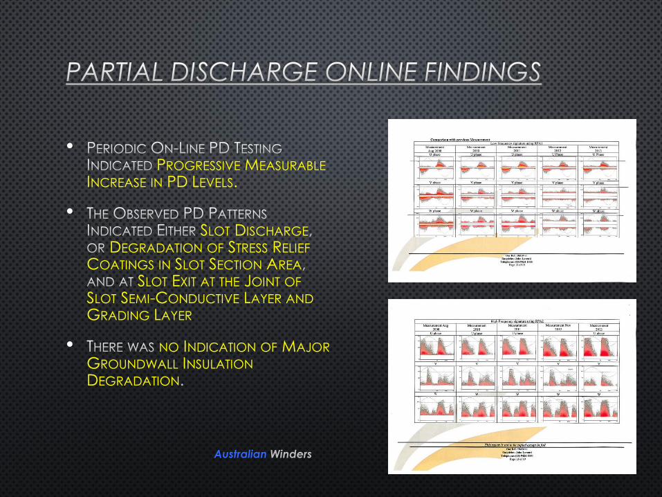
•PROGRESSIVE MEASURABLE
INCREASE IN PD LEVELS.
•SLOT DISCHARGE
DEGRADATION OF STRESS RELIEF
COATINGS IN SLOT SECTION AREA
SLOT EXIT AT THE JOINT OF
SLOT SEMI-CONDUCTIVE LAYER AND
GRADING LAYER
• NO INDICATION OF MAJOR
GROUNDWALL INSULATION
DEGRADATION

Australian Winders

•
•
•
•
Australian Winders
•
Australian Winders

•
•
Australian Winders

Australian Winders
Slot 31 had no corona
protection left!

•
• PLEASE NOTE SLOT #6 CE
Australian Winders

•
•
•
•
Australian Winders

•
•
•
Australian Winders

•
• PLEASE NOTE SLOT #6 CE
Australian Winders

•
Australian Winders

Australian Winders
•
•
•
•
•
Australian Winders

STATOR WINDING LEADS INVERSION
Purpose:• The Highest Gradient Across the Stator Ground Wall Insulation (Line to Ground Voltage)
is At The Main Output High Voltage (HV) Lead End. Thus the HV Winding Side Incurs the Highest In-Service PD Degradation (Internally and Externally)
• The Lowest Dielectric Gradient Across the Stator Ground Wall Insulation Occurs at the Neutral End of the Winding. The Neutral Winding End Is Unaffected by the PD Damage
• By Reversing/Inverting Stator Leads (Active Side and Neutral Side), the Neutral Side which is Not Affected by PD Erosion is Now Connected to the HV Output Side. The Bars that were Previously Connected to the HV Side are Now Exposed to Very Low Voltage Stresses and are not Expected to Incur Further PD Degradation
• By Stator Winding Leads Inversion it is Possible to Appreciably Extend the Winding Life by Shifting Weaker Degraded Coils Near the Neutral End Under Lower Dielectric Stress
• Stator Leads Inversion Can Only Mitigate and Prolong Winding Life Due to PD Damage, and Before Embarking on the Lead Reversal, it is, of Course, Necessary to Fully Assess Stator Winding Condition Due to Other Degradation Mechanisms (Thermal, Mechanical and Environmental)

STATOR WINDING LEADS INVERSION
Stator Winding Voltage Division:• The Voltage to Ground Along Stator Phase Winding Divides Linearly from Full Voltage
to Ground at Phase Terminals (Vph), to Zero Volts to Ground at Star Point as Depicted Below

STATOR WINDING LEADS INVERSION
Lead Inversion Design:• Design and Design Coordination was Done by
GMECS (Dr. Michael Znidarich – Director
Electrical Machinery Consultant)
• 3D Modelling and Drafting was Done by Owner’s Contractor D.A.K. Systems (David Knowling – Owner)
• Manufacturing and Installation was Done byAustralian Winders (Tony O’Brien - Managing Director/Owner)
STATOR WINDING LEADS INVERSION
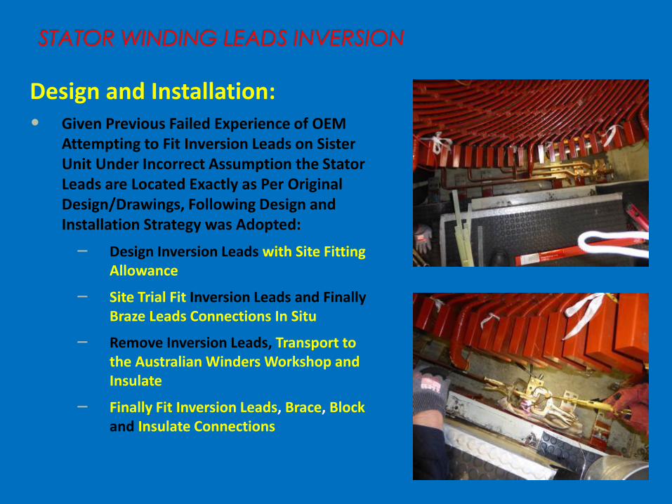
Design and Installation:• Given Previous Failed Experience of OEM
Attempting to Fit Inversion Leads on Sister Unit Under Incorrect Assumption the Stator Leads are Located Exactly as Per Original Design/Drawings, Following Design and Installation Strategy was Adopted:
– Design Inversion Leads with Site Fitting Allowance
– Site Trial Fit Inversion Leads and FinallyBraze Leads Connections In Situ
– Remove Inversion Leads, Transport to the Australian Winders Workshop and Insulate
– Finally Fit Inversion Leads, Brace, Blockand Insulate Connections

STATOR WINDING LEADS INVERSION
Installation:

FINAL STATOR WINDING OFF-LINE PD TESTS
Final Off-Line PD Test Results:
• The Final (as Left) Stator Winding Off-Line PD Tests were Carried Using Both Lower Frequency Band (100-800 kHZ) and Higher Frequency Band (2-20 MHZ). These Tests Provided an Indication of Effectiveness of Corona System Repairs, but not the Operational PD Reduction Contributed by the Inversion Leads
• In Every Case there was Significant Reduction in Off-Line PD Magnitudes, Signifying Good Success of Stator Winding PD Repairs

FINAL STATOR WINDING OFF-LINE PD TESTS
Graphical Comparison of Off-Line PD Test Results:

ON-LINE PD TESTING FOLLOWING RETURN TO
SERVICE
On Line PD Test Results:
• The First On-Line Stator Winding PD Tests were Carried Immediately Post Refurbishment and Fitting of Inversion Leads Using Both Lower Frequency Band (100-800 kHZ) and Higher Frequency Band (2-20 MHZ), and Compared to the Test Results of Periodic On-Line PD Monitoring Obtained Before Repairs.
• When Using Low Frequency Band (100 – 800 kHZ), there was no PD Signal Detectable Above Background Interference.
• When Using High Frequency Band (2 – 20 MHZ) Phases “U” and “V” were Virtually PD Free, and Magnitude of PD Discharge for Phase “W” was Significantly Reduced

ON-LINE PD TESTING FOLLOWING RETURN TO
SERVICEComparison of On Line PD Test Results (March 2014 Before Repairs and Leads Inversion) andNovember 2014 (Following Repairs and Leads Inversion):

CONCLUSION
It Can be Concluded that Both,Applied PD Repair Strategies, and Application of Stator Phase/Neutral Inversion Leads Combined, Contributed to Significant Reduction in PD Activity and Extension of Stator Winding Operational LifeProject was completed 4 days ahead of schedule, with no LTI’s