tool engineering manufacture, workmanship, and …...platings, ceramic coatings, chromates, oxides,...
TRANSCRIPT

Released 06/09/2011
TOOL ENGINEERING
MANUFACTURE, WORKMANSHIP, AND SHOP PRACTICE SPECIFICATION NUMBER: TER-01001 REVISION: L

Released 06/09/2011
SPECIFICATION NUMBER: TER-01001 REVISION: L Preparer
Bryan D Smith
DATE
06/01/2011 Safety
James P Smith
DATE
06/01/2011
ResponsibleEng
Cameron Keland Draney
DATE
06/01/2011 QE
Terral W Morgan
DATE
06/02/2011
Management
Bryan D Smith
DATE
06/02/2011 Management
Kent Calvin Stephens
DATE
06/02/2011
Management
Philip W Petersen
DATE
06/03/2011 Management
James Lee Ekstrom
DATE
06/09/2011

Document No: TER-01001 Revision: L
W O R K M A NSH IP A ND SH OP PR A C T I C E ST A ND A RD
for Manufacture of Special Tooling and Equipment
Supersedes TER-01001, Rev K (released October 11, 2010)
ATK Launch Systems Inc. P. O. Box 707 Brigham City, UT 84302-0707 (435) 863-3511
T E R-01001 Page 2 of 20 W O R K M A NSH IP A ND SH OP PR A C T I C E ST A ND A RD
T A B L E O F C O N T E N TS
REVISION HISTORY 3 1.0 SCOPE: 4
1.1 Scope and Application 4 1.2 Conflict of Documents 4
2.0 APPLICABLE DOCUMENTS: 4 2.1 Government Documents 4 2.2 Non-Government Documents 4
3.0 REQUIREMENTS: 5 3.1 General Shop Practices 5 3.1.1 Blending Surface 5 3.1.2 Mismatch of Machined Surfaces 5 3.1.3 Machining Centers 5 3.1.4 Breaking Sharp Edges 5 3.1.5 Chamfers for Internal Thread Ends 5 3.1.6 Chamfers for External Thread Ends 6 3.1.7 Thread Length 6 3.1.8 Repair of Damaged Threaded Holes 6 3.1.9 Dimensions of Finished Parts 6 3.1.10 Paint and Protective Coatings 6 3.2 Surface Roughness, Waviness and Lay 8 3.2.1 Surface Roughness Not Specified 8 3.2.2 Roughness Height Rating Values 8 3.2.3 Key Slots 9 3.2.4 Keyways 9 3.3 Materials 9 3.4 Surface Cleanliness 9 3.5 General Cleanliness 9 3.6 Installation of Rigid Tubing 10 3.6.1 Recommended Rigid Tubing Minimum Bend Radius 10 3.6.1.1 Flattening Limitations 10 3.6.1.2 Wrinkles and Scratches 10 3.6.2 Flaring Tubing 10 3.6.3 Torquing of AN Fittings 10 3.7 Torquing of Threaded Fasteners 11 3.8 Seals, Gaskets, Burst Discs, and Diaphragms 13 3.9 Hydraulic System Testing 13 3.10 Marking of Parts 13 3.11 Machining Graphite or Phenolics 13 3.12 Safety Wiring 14 3.13 Fluid System (Hydraulic, Pneumatic, Inert, Gas, Propellant etc.)
Cleanliness Requirements 14 3.14 Fastener Requirements 15 3.14.1 Approved Fastener Distributors 15 3.14.2 Approved Fastener Manufacturers 15 3.14.3 Fastener Purchase / Quality Requirements 15 3.14.4 Exception 18 3.15 Bonding Requirements 18 3.15.1 Adhesive Selection 18 3.15.2 Surface Preparation 20 3.16 General Workmanship Instructions for All Bonding 20

T E R-01001 Page 3 of 20 W O R K M A NSH IP A ND SH OP PR A C T I C E ST A ND A RD
REVISION HISTORY
Revision Description - Original Release A Unknown, released as 001. B Unknown, released as 002. C Changed Title, adds section to address coating methods, updates document to ATK
Launch Systems, and corrects minor errors. D Added Section 3.14, Fastener Requirements.
Corrected Section 3.1.10, Method 13 SP-VGF-3.1.1. Bake out per GPI000036, paragraph 4.6 a. option 1, 2, 3, or 4
as specified on the drawing. E Added TOC
Updated Section 2.0 to add ASME references Updated Section 3.14 to address machine screws and correct ASME references. Added Section 3.14.6 (Other Fasteners)
F Changed Section 2.0 to removed references not applicable. Changed Section 3.14:
Updated 3.14.1 requirements. Updated 3.14.2 and 3.14.3 to eliminate Fastenal Co. as the sole source supplier. Deleted 3.14.4 and 3.14.5 to allow use in-house fasteners for tooling fabrication.
G Added paint methods 2 and 4 to Section 3.1.10. Changed Section 3.14:
Reference to critical fastener definition. Require certifications on critical fasteners and upon request on other fasteners. Allow hex head fasteners to come from foreign or domestic suppliers. Corrected torque ranges in Section 3.2.2.2, Table II. Corrected torque references in Section 3.7, Table V. Added Sections 3.15, Bonding Requirements.
H Revised Section 2.2 Non-Government Documents Revised Section 3.14 Fasteners
J Revised section 3.12 Safety Wiring K Revised sections 2.2
Added information to section 3.1.10 Removed reference to Conoco HD2 lubricant in section 3.7 Rewrote section 3.14
L Added Socket Button and Flat Countersunk Head Cap Screws to section 3.14.3 Revised section 3.14.4.
T E R-01001 Page 4 of 20 W O R K M A NSH IP A ND SH OP PR A C T I C E ST A ND A RD
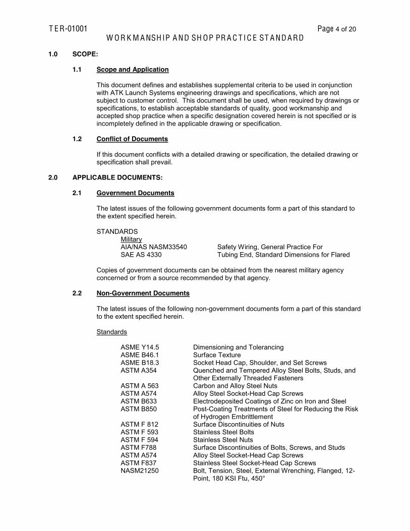
1.0 SCOPE:
1.1 Scope and Application This document defines and establishes supplemental criteria to be used in conjunction
with ATK Launch Systems engineering drawings and specifications, which are not subject to customer control. This document shall be used, when required by drawings or specifications, to establish acceptable standards of quality, good workmanship and accepted shop practice when a specific designation covered herein is not specified or is incompletely defined in the applicable drawing or specification.
1.2 Conflict of Documents If this document conflicts with a detailed drawing or specification, the detailed drawing or
specification shall prevail.
2.0 APPLICABLE DOCUMENTS:
2.1 Government Documents The latest issues of the following government documents form a part of this standard to
the extent specified herein. STANDARDS
Military AIA/NAS NASM33540 Safety Wiring, General Practice For SAE AS 4330 Tubing End, Standard Dimensions for Flared Copies of government documents can be obtained from the nearest military agency concerned or from a source recommended by that agency.
2.2 Non-Government Documents The latest issues of the following non-government documents form a part of this standard
to the extent specified herein. Standards ASME Y14.5 Dimensioning and Tolerancing ASME B46.1 Surface Texture ASME B18.3 Socket Head Cap, Shoulder, and Set Screws
ASTM A354 Quenched and Tempered Alloy Steel Bolts, Studs, and Other Externally Threaded Fasteners
ASTM A 563 Carbon and Alloy Steel Nuts ASTM A574 Alloy Steel Socket-Head Cap Screws ASTM B633 Electrodeposited Coatings of Zinc on Iron and Steel ASTM B850 Post-Coating Treatments of Steel for Reducing the Risk
of Hydrogen Embrittlement ASTM F 812 Surface Discontinuities of Nuts ASTM F 593 Stainless Steel Bolts ASTM F 594 Stainless Steel Nuts ASTM F788 Surface Discontinuities of Bolts, Screws, and Studs ASTM A574 Alloy Steel Socket-Head Cap Screws ASTM F837 Stainless Steel Socket-Head Cap Screws NASM21250 Bolt, Tension, Steel, External Wrenching, Flanged, 12-
Point, 180 KSI Ftu, 450°

T E R-01001 Page 5 of 20 W O R K M A NSH IP A ND SH OP PR A C T I C E ST A ND A RD
NASM8984 Nuts, Self-Locking, Steel, 260 Ftu, 450° SAE AS 4330 Design Standard, Tubing, Flared, Standard Dimensions SAE J429 Mechanical and Material Requirements for Externally
Threaded Fasteners SAE J995 Mechanical and Material Requirements for Steel Nuts
ASME documents can be obtained from the American Society of Mechanical Engineers, United Engineering Center, 345 East 47th Street, New York, NY 10017. ASTM documents can be obtained from World Engineering Xchange, Ltd, 2671 West 81st Street, Hialeah, FL 33016, USA SAE documents can be obtained from The Engineering Society for Advancing Mobility Land Sea Air and Space International, 400 Commonwealth Drive, Warrendale, PA 15096 NAS documents can be obtained from the Aerospace Industries Associations of America, Inc., 1000 Wilson Blvd., Arlington, VA 22209
3.1 General Shop Practices
3.1.1 Blending Surface Connecting curved surfaces or curved and plain surfaces shown as a tangent
must blend smoothly. Attention is drawn to the note "Machined inside corners to have radius of .020 inch - .040 inch" appearing on drawings. This requires that, unless otherwise specified, all internal corners of machined parts shall have a radius within the tolerance given.
3.1.2 Mismatch of Machined Surfaces When two or more machining cuts are required to produce a surface delineated
on the drawing as being a theoretical single surface, the maximum misalignment between intersecting or adjacent surfaces shall not exceed 0.005 inch or must be contained within the limits of dimensional size, whichever is the smaller.
3.1.3 Machining Centers Center holes may be required in shafts, spindles, and other cylindrical or
symmetrical parts to receive machine centers on which the work pieces are supported during manufacturing or inspection. Unless otherwise specified, their use is optional.
3.1.4 Breaking Sharp Edges Unless otherwise stated on the drawing, the standard to which sharp edges must
be broken is from 0.010 to 0.020 inch. Any method may be used to break such edges, provided a radius or a flat without sharp corners is produced within the tolerance given. A sharp-cornered flat or a concave radius at the edge is not acceptable. If a sharp corner is required, the drawing will so specify. Dimensions to intersecting surfaces shall be made before breaking or shall be measured to the intersections, which existed before breaking. On sheet metal parts of 1/32-inch thickness or less, the breaking of edges is not mandatory; however, such edges shall be free from burrs. The breaking of edges does not apply to elastomers such as rubber and 'soft' plastics.
3.1.5 Chamfers for Internal Thread Ends

T E R-01001 Page 6 of 20 W O R K M A NSH IP A ND SH OP PR A C T I C E ST A ND A RD
Unless otherwise noted on the drawing, a chamfer with an included angle of 80
to 120 degrees shall be used at internal thread start. The minimum diameter of the chamfer shall be the major diameter of the thread. The maximum diameter of the chamfer shall be the major diameter of the thread plus 0.030 inch.
3.1.6 Chamfers for External Thread Ends Chamfers shall be provided at the ends of externally threaded parts. The
chamfer shall extend to the minor diameter of the thread. The angle of the chamfer shall be 45 plus or minus 5 degrees. The minimum length of the chamfer shall be the height of the external thread.
3.1.7 Thread Length The thread length dimensions indicated on the drawing are the gaging length or
the length of threads having full form. Three perfect or imperfect threads are allowable beyond such limit for lead of tap where hole depth permits.
3.1.8 Repair of Damaged Threaded Holes Damaged threaded holes may be repaired by installing threaded inserts
(Keensert or Helicoil) in accordance with manufacturer's instructions, or by plugging and re-tapping. The decision to repair, and method of repair, shall be the responsibility of ATK Launch Systems Tool Engineering.
3.1.9 Dimensions of Finished Parts Unless otherwise specified, all dimensions on components show only the end
product design. Since the end product design dimensions are for only the final form and sizes without reference to methods of manufacture, all these dimensions are applicable after operations such as heat-treating, stress relieving, aging, sandblasting, buffing, etc. If these operations are required to maintain dimensional stability, they may not be specified on the drawing, but should be added to the fabrication as required.
Dimensions to a cast or forged surface are to apply to the general level of such a surface and local depressions or excrescencies are to be ignored. When a drawing does not specify whether dimensions apply before or after application of a surface coating, the following interpretation shall be used: a. Unless otherwise specified, dimensional limits and surface roughness
designations apply after the application of inorganic finishes, such as platings, ceramic coatings, chromates, oxides, etc.
b. Unless otherwise specified, where organic finishes such as lacquers,
varnishes, enamels, plastic coatings, teflon, etc., are used, dimensional and surface roughness designations must be met prior to the application of the organic finish.
3.1.10 Paint and Protective Coatings Method 1: Yellow paint for metal

T E R-01001 Page 7 of 20 W O R K M A NSH IP A ND SH OP PR A C T I C E ST A ND A RD
Grit blast, solvent clean and apply one coat light gray Aqua-Lac® primer, 32GY025 (35-583309), and one coat yellow water-based polyurethane, 135YW001 (35-583296), Prime Coatings, (Pewaukee, WI.).
Method 2 Gray paint for metal Grit blast, solvent clean and apply one coat light gray Aqua-Lac® primer, 32GY025 (35-583309), and one coat gray water-based polyurethane, 135GY001 (35-583297), Prime Coatings, (Pewaukee, WI.).
Method 3 White paint for metal
Grit blast, solvent clean and apply one coat light gray Aqua-Lac® primer, 32GY025 (35-583309), and one coat white water-based polyurethane, 135WE003 (35-583307), Prime Coatings, (Pewaukee, WI.).
Method 4 Black paint for metal
Grit blast, solvent clean and apply one coat light gray Aqua-Lac® primer, 32GY025 (35-583309), and one coat black water-based polyurethane, 135BK001, Prime Coatings, (Pewaukee, WI.).
Method 5 Yellow paint for wood
Apply one coat white acrylic emulsion primer, 35933 (35-583295), and one coat yellow water-based polyurethane, 135YW001 (35-583296), Prime Coatings, (Pewaukee, WI.).
Method 6 Gray paint for wood
Apply one coat white acrylic emulsion primer, 35933 (35-583295), and one coat gray water-based polyurethane, 135GY001 (35-583297), Prime Coatings, (Pewaukee, WI.).
Method 7 Selective plating
Using a selective (Brush Plating) electro-deposition per MIL-STD-8865, provide a 0.0005 0.0007 inch thick zinc base coating, followed by a 0.0003 0.0005 inch thick nickel top coat.
Method 8 Electro-less nickel
Using an electro-less nickel plating method per AMS 2404, provide a 0.0003 0.0005 inch thick nickel coat.
Method 9 Black oxide Black oxide coat per SAE AMS 2485 or MIL-STD-13924. Method 10 Black anodize Black anodize per SAE AMS 2472. Method 11 Clear anodize Clear anodize per SAE AMS 2471
Method 12 Plastic flame-coat
Grit blast, solvent clean and apply plastic flame-coat, PF111/XXX (22-5781XX) per manufactures specifications. Plastic Flame-coat Systems (Big Spring, TX.).

T E R-01001 Page 8 of 20 W O R K M A NSH IP A ND SH OP PR A C T I C E ST A ND A RD
Method 13 Teflon Coat
Teflon coat per ATK Launch Systems Inc., specification GPI000036. All dimensions apply prior to coating. Bake out per GPI000036, paragraph 4.6 a. option 1, 2, 3, or 4 as specified on the tool drawing. Fuse FEP Coats out per GPI000036, paragraph 5.5 c. option 1, 2, 3, or 4 as specified on the tool drawing.
Method 14: Yellow paint for metal in outside or other harsh environments Grit blast and solvent clean per instructions. Apply two coats of grey primer (HS9381407) and two coats of yellow polyurethane topcoat (9844419) per manufacturers specifications. Rust-Oleum Corp. (Vernon hills, IL)
Method 15: Grey paint for metal in outside or other harsh environments Grit blast and solvent clean per instructions. Apply two coats of grey primer (HS9381407) and two coats of grey polyurethane topcoat (9886419) per specifications. Rust-Oleum Corp. (Vernon hills, IL)
3.2 Surface Roughness, Waviness and Lay Surface roughness, waviness and lay requirements shall be interpreted in accordance
with ASME B46.1, latest edition.
3.2.1 Surface Roughness Not Specified When the surface roughness is not specified, the surface can be left as shaped
roughness height (micro-inch), as listed in Table IA below:
Table IA Process
Roughness Height (Micro-inch)
Forged 500 Hot Rolled 1000 Extruded 125 Cold Rolled 125 Investment Cast 125 Flame Cut 1000 Die Cast 63 Sawed 1000
3.2.2 Roughness Height Rating Values Surface roughness height for surfaces listed in Table IB below shall not be
greater than indicated.
Table IB Surfaces Roughness Height
(Micro-inch) Reamed holes or thread surfaces 63 Drilled holes 250 Splines, serrations, and broached surfaces 63 Spotfaced surfaces 125 Counterbore 125 Countersink 125
T E R-01001 Page 9 of 20 W O R K M A NSH IP A ND SH OP PR A C T I C E ST A ND A RD
3.2.2.1 Finishes of Small Radii or Changes in Contour Unless surface finishes are designated on small radii or changes in
contour, the finish is to be equivalent to the least quality of surface finish required on adjoining surfaces.
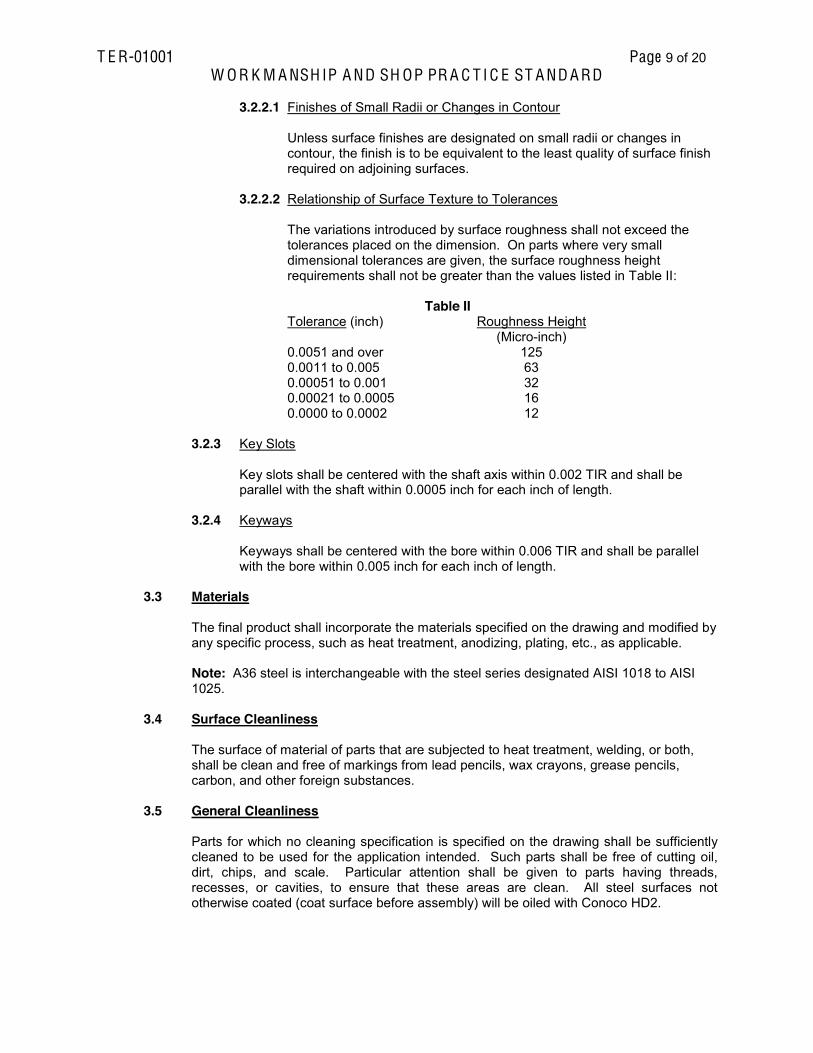
3.2.2.2 Relationship of Surface Texture to Tolerances The variations introduced by surface roughness shall not exceed the
tolerances placed on the dimension. On parts where very small dimensional tolerances are given, the surface roughness height requirements shall not be greater than the values listed in Table II:
Table II
Tolerance (inch) Roughness Height (Micro-inch)
0.0051 and over 125 0.0011 to 0.005 63 0.00051 to 0.001 32 0.00021 to 0.0005 16 0.0000 to 0.0002 12
3.2.3 Key Slots Key slots shall be centered with the shaft axis within 0.002 TIR and shall be
parallel with the shaft within 0.0005 inch for each inch of length. 3.2.4 Keyways Keyways shall be centered with the bore within 0.006 TIR and shall be parallel
with the bore within 0.005 inch for each inch of length.
3.3 Materials The final product shall incorporate the materials specified on the drawing and modified by
any specific process, such as heat treatment, anodizing, plating, etc., as applicable.
Note: A36 steel is interchangeable with the steel series designated AISI 1018 to AISI 1025.
3.4 Surface Cleanliness The surface of material of parts that are subjected to heat treatment, welding, or both,
shall be clean and free of markings from lead pencils, wax crayons, grease pencils, carbon, and other foreign substances.
3.5 General Cleanliness Parts for which no cleaning specification is specified on the drawing shall be sufficiently
cleaned to be used for the application intended. Such parts shall be free of cutting oil, dirt, chips, and scale. Particular attention shall be given to parts having threads, recesses, or cavities, to ensure that these areas are clean. All steel surfaces not otherwise coated (coat surface before assembly) will be oiled with Conoco HD2.

T E R-01001 Page 10 of 20 W O R K M A NSH IP A ND SH OP PR A C T I C E ST A ND A RD
3.6 Installation of Rigid Tubing
3.6.1 Recommended Rigid Tubing Minimum Bend Radius The minimum allowable rigid tubing bend radius (measured to the centerline of
the tubing) specified in Table III requires no approval and shall be used wherever possible. Flattening, wrinkles, and scratch requirements on all bends shall be as specified in 3.6.1.1 and 3.6.1.2.
Table III
Minimum Allowable Bend Radius Tube OD,
(inch) Minimum
Bend Radius Tube OD,
(inch) Minimum
Bend Radius 1/8 3/8 1-1/8 3-1/2 3/16 7/16 1-1/4 3-3/4 ¼ 9/16 1-3/8 5
5/16 11/16 1-1/2 5 3/8 15/16 1-5/8 6 7/16 1-1/4 1-3/4 7 ½ 1-1/4 2 8 5/8 1-1/2 2-1/4 9 ¾ 1-3/4 2-1/2 10 7/8 2 2-3/4 11 1 3 3 12
3.6.1.1 Flattening Limitations Tubes for fluid systems with working pressures of 1000 psi or greater
shall not be flattened more than 5 percent, and for fluid systems with working pressures less than 1000 psi shall not be flattened more than 10 percent. Flattened in the cross section is defined by the following formula:
Flattened = max. OD - min. OD x 100 percent nominal OD 3.6.1.2 Wrinkles and Scratches a. For fluid systems with working pressures 500 psi or greater, there shall
be no wrinkles or kinks deeper than 1 percent of tubing OD and no scratches deeper than 5 percent of the nominal tubing wall thickness.
b. For fluid systems with working pressures of less than 500 psi, there shall
be no wrinkles or kinks deeper than 2 percent of tubing OD and no scratches deeper than 10 percent of the nominal tubing wall thickness.
3.6.2 Flaring Tubing The flared ends of tubing shall meet all requirements of Standard SAE AS4330. 3.6.3 Torquing of AN Fittings The acceptable torque values for AN type fittings used on the flared ends of rigid
tubing shall be in accordance with Table IV:

T E R-01001 Page 11 of 20 W O R K M A NSH IP A ND SH OP PR A C T I C E ST A ND A RD
Table IV
Allowable Torques for AN Type Fittings Used with Rigid Tubing
(Torque Limit in. -lb) Tube OD
(inch) Aluminum Alloy Tubing Steel Tubing
Minimum Maximum Minimum Maximum 1/8 -- -- -- -- 3/16 -- -- 90 100 1/4 40 65 135 150 5/16 60 80 180 200 3/8 75 125 270 300 1/2 150 250 450 500 5/8 200 350 650 700 3/4 300 500 900 1000 1 500 700 1200 1400
1 1/4 600 900 -- -- 1 1/2 600 900 -- -- 1 3/4 -- -- -- --
2 -- -- -- --
3.7 Torquing of Threaded Fasteners Unless otherwise specified, the acceptable torque values for threaded fasteners shall be
in accordance with Table V. Special lubricants shall not be used for the assembly of threaded fasteners unless specifically called out on the drawing. Use the lubricated value if the fasteners are coated with high stress ability lubricants (never SeeZ compound, graphite and oil, molybdenum disulphite, colloidal copper, and white lead are examples).

T E R-01001 Page 12 of 20 W O R K M A NSH IP A ND SH OP PR A C T I C E ST A ND A RD
Table V Torque Values for Bolted Installation a b
Low Carbon Steel Bolts and Nuts (Grade 2)
Higher Strength Steel Bolts and Nuts (Grade 5 or higher)
Tightening Torque c f Tightening Torque d
Dry Lubricated Dry Lubricated Min. Max. Min. Max. Min. Max. Min. Max.
Size lb-inch lb-inch lb-inch lb-inch 2-56 2.2 2.5 2-64 2.7 3.0 3-48 3.5 3.9 3-56 4.0 4.4 4-40 4.5 5 3.6 4 7 8 5 6 4-48 5 6 4.5 5 8 9 6 7 6-32 9 10 7 8 14 16 11 12 6-40 11 12 8 9 16 18 12 13 8-32 17 19 13 14 27 30 20 22 8-36 18 20 14 15 28 31 21 23
10-24 24 27 19 21 39 43 29 32 10-36 28 31 21 23 44 49 32 36 1/4-20 59 66 44 49 86 96 68 75 1/4-28 68 76 50 56 108 120 77 86
lb-ft lb-ft lb-ft lb-ft
5/16-18 10 11 7 8 15 17 12 13 5/16-24 11 12 8 9 17 19 13 14 3/8-16 18 20 14 15 27 30 21 23 3/8-24 21 23 15 17 32 35 23 25
7/16-14 27 30 22 24 45 50 32 35 7/16-20 32 35 23 25 50 55 36 40 1/2-13 45 50 32 35 67 75 50 55 1/2-20 50 55 36 40 81 90 59 65
9/16-12 59 65 45 50 99 110 72 80 9/16-18 68 75 50 55 100 120 81 90 5/8-11 81 90 63 70 135 150 99 110 5/8-18 90 100 72 80 162 180 117 130 3/4-10 144 160 108 120 234 260 180 200 3/4-16 162 180 126 140 270 300 198 220 7/8-9 126 140 99 110 360 400 270 300
7/8-14 140 155 108 120 396 440 288 320 1-8 198 220 144 160 522 580 396 440
1-12 216 240 153 170 576 640 432 480 1 1/8-7 270 300 198 220 720 800 540 600 1 1/8-12 306 340 234 260 792 880 594 660 1 1/4-7 378 420 288 320 1008 1120 756 840 1 1/4-12 414 460 324 360 1116 1240 828 920 1 3/8-6 504 560 378 420 1314 1460 990 1100 1 3/8-12 576 640 414 460 1512 1080 1134 1260 1 1/2-6 666 740 504 560 1746 1940 1314 1460 1 1/2-12 756 840 558 620 1980 2200 1476 1640
Table V NOTES
a. These torque values are only applicable in steel (or in steel inserts) when the length of thread engagement is at least the same as the nominal diameter of the thread.
b. When shear-type nuts and thin nuts are used where the height of the nuts is approximately
half the size of the major diameter of the threads, the torque values shall be reduce by 50 percent.

T E R-01001 Page 13 of 20 W O R K M A NSH IP A ND SH OP PR A C T I C E ST A ND A RD
c. The low carbon tightening torque values are for general use on standard bolts, studs, and
nuts which have no grade or identification marking.
d. These tightening torque values are to be used only with standard Grade 5 or better bolts, studs, and nuts. Grade 5 bolts and studs are identified by three radial dashes 120 degrees apart on the heads of bolts and on the nut end of studs. Grade 5 nuts are identified by three radial dashes spaced 120 degrees apart on the top face of the nut, see Hd cap screws. Grade 8 bolts, studs, and nuts which are identified by six radial dashes 60 degrees apart, could have higher torque values than specified herein to utilize their full capability.
Unmarked Grade 5 Grade 8
e. These torque values are only applicable when the length of thread engagement in cast iron is
at least 1-1/2 times the nominal diameter of the threads. f. These torque values are only applicable when the length of thread engagement in aluminum
is at least 3 times the nominal diameter of the threads. 3.8 Seals, Gaskets, Burst Discs, and Diaphragms A part designated as a seal, gasket, burst disc, or diaphragm shall be free from
scratches, wrinkles, or indentations and shall be suitably protected in handling. 3.9 Hydraulic System Testing A hydraulic system will be defined as such things as (but not necessarily limited to only)
lines, vessels, valves, and fittings that enclose pressure higher than the environment. Each hydraulic system will be tested to 150% of the working pressure on at least the first article. For a propellant system test, water can be used. For an oil system, it is recommended that the oil used in the system also be used during the test.
3.10 Marking of Parts When no marking requirements are specified on the applicable drawing for a part or
separable detail, the part or detail shall be marked with the drawing number and the applicable three digit detail number, if at all possible. When marking is not possible, it shall be tagged or packaged and the appropriate marking placed on the tag or package. When additional markings are needed, they shall be made by the same marking or identification method or by any permanent marking method that will not render a machined surface useless. To ensure proper reassembly, all subassemblies and detail parts may be coded and indexed in relation to their adjacent parts with permanent type letters and/or numbers and/or arrows.
3.11 Machining Graphite or Phenolics Liquid coolants shall not be used in the machining of graphite or phenolics unless
specifically authorized by a note on the engineering drawing.
T E R-01001 Page 14 of 20 W O R K M A NSH IP A ND SH OP PR A C T I C E ST A ND A RD
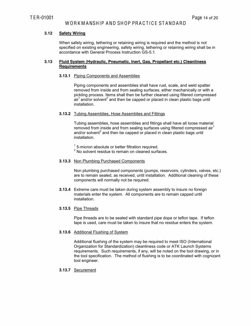
3.12 Safety Wiring When safety wiring, tethering or retaining wiring is required and the method is not
specified on existing engineering, safety wiring, tethering or retaining wiring shall be in accordance with General Process Instruction GS-5.1.
3.13 Fluid System (Hydraulic, Pneumatic, Inert, Gas, Propellant etc.) Cleanliness
Requirements
3.13.1 Piping Components and Assemblies Piping components and assemblies shall have rust, scale, and weld spatter
removed from inside and from sealing surfaces, either mechanically or with a pickling process. Items shall then be further cleaned using filtered compressed air1 and/or solvent2 and then be capped or placed in clean plastic bags until installation.
3.13.2 Tubing Assemblies, Hose Assemblies and Fittings Tubing assemblies, hose assemblies and fittings shall have all loose material
removed from inside and from sealing surfaces using filtered compressed air1 and/or solvent2 and then be capped or placed in clean plastic bags until installation.
1 5-micron absolute or better filtration required. 2 No solvent residue to remain on cleaned surfaces. 3.13.3 Non Plumbing Purchased Components Non plumbing purchased components (pumps, reservoirs, cylinders, valves, etc.)
are to remain sealed, as received, until installation. Additional cleaning of these components will normally not be required.
3.13.4 Extreme care must be taken during system assembly to insure no foreign
materials enter the system. All components are to remain capped until installation.
3.13.5 Pipe Threads Pipe threads are to be sealed with standard pipe dope or teflon tape. If teflon
tape is used, care must be taken to insure that no residue enters the system. 3.13.6 Additional Flushing of System Additional flushing of the system may be required to meet ISO (International
Organization for Standardization) cleanliness code or ATK Launch Systems requirements. Such requirements, if any, will be noted on the tool drawing, or in the tool specification. The method of flushing is to be coordinated with cognizant tool engineer.
3.13.7 Securement

T E R-01001 Page 15 of 20 W O R K M A NSH IP A ND SH OP PR A C T I C E ST A ND A RD
In many applications it may be necessary to restrain, protect, or guide hydraulic
and pneumatic hose or tubing assemblies to protect them from damage by unnecessary flexing, pressure surges and contact with other mechanical components. These reference documents may be used as suggested guidelines (REF. SAE 21.104 and JIC/NFPA.)
3.14 Fastener Requirements
Note: This Fastener Requirements section specifies the engineering and procurement/quality requirements for fasteners. Unless otherwise specified on the engineering drawing, the following fasteners shall be considered semi-critical. Socket Head Cap Screws Low Head Cap Screws Flat Head Cap Screws Button Head Cap Screws Socket Head Shoulder Screws Hex Cap Screws, Grade 5 and Grade 8 Hex Bolts, Grade 5 and Grade 8 Hex Nuts, Grade 5 and Grade 8
3.14.1 Critical Fastener Controls and Engineering Requirements Shall be designated on the engineering drawing by a flag note with In-house testing
requirements identified in the note. Shall be 12 Point Fasteners and nuts (as applicable) meeting the following
specifications: o Bolts per NASM21250 o Nuts per NAS1804
Note: Do not use cadmium plated fasteners in areas above 400 deg F
Shall be purchased through a Purchase Requisition / Purchase Order. Fasteners shall be procured through an ATK approved supplier. For manufacturers of tooling, ATK will supply the critical fasteners. Shall be made of domestic materials and manufactured by approved domestic
manufacturers. Shall be 100% visually inspected for quench cracks using a device that provides 10 power
magnification. Acceptance criteria no cracks allowed. A complete certification package (C of C, material certifications, test reports,
inspection results, etc.) shall be required to be submitted with shipment to ATK.
3.14.2 Semi-critical Fasteners Controls r -
fastener. For in-house fabrication, rework, or repair, fasteners should be available in Supply
part number. For in-house fabrication, shall be purchased through a Purchase Requisition or
established fastener Blanket Purchase Agreement. Fasteners shall be procured through an ATK approved supplier. Shall be made of domestic materials and supplied by approved domestic supplier. A certificate of conformance stating compliance to the requirements of this document
shall be required to be submitted with shipment to ATK.

T E R-01001 Page 16 of 20 W O R K M A NSH IP A ND SH OP PR A C T I C E ST A ND A RD
The supplier shall maintain certifications and be able to provide them to ATK upon
request.
3.14.3 Semi-critical Engineering Requirement Socket Head Cap Screws and Shoulder Screws 1. Shall comply with ASME B18.3 and all subsequent specifications invoked per ASME
B18.3 and; a. Fasteners made from Alloy Steel material shall comply with ASTM A574. b. Fasteners made from Alloy Steel material shall be black oxide coated. c. Fasteners made from Stainless and Corrosion Resistant Steel material shall
comply with ASTM F837, Alloy group, Condition, and Alloy selection as specified on engineering.
d. Fasteners shall comply with requirements of ASTM F788. Socket Button and Flat Countersunk Head Cap Screws 1. Shall comply with ASME B18.3 and all subsequent specifications invoked per ASME
B18.3 and: a. Fasteners made from Alloy Steel material shall comply with ASTM F835. b. Fasteners made from Alloy Steel material shall be black oxide coated. c. Fasteners made from Stainless and Corrosion Resistant Steel material shall
comply with ASTM F879, Alloy group, Condition, and Alloy selection as specified on engineering.
d. Fasteners shall comply with requirements of ASTM F788. Hex Head Bolts and Hex Cap Screws 1. Unless otherwise specified on the engineering drawing, fasteners
diameter shall comply with SAE J429 (Grades 5 or 8) requirements and all subsequent specifications invoked per SAE J429. If no grade is specified on the engineering drawing for Hex fasteners, grade 5 is implied.
2. Unless otherwise specified on the engineering drawing, fasteners
diameter shall comply with ASTM A354 ,Grade BC (Grade 5) or BD (Grade 8) requirements and all subsequent specifications invoked per ASTM A354. If no grade is specified on the engineering drawing for Hex fasteners, grade BC (5) is implied.
3. Fasteners made from Stainless and Corrosion Resistant Steel material shall comply
with ASTM F593, Alloy group, Condition, and Alloy selection as specified on engineering drawing.
4. Fasteners shall comply with requirements of ASTM F788. 5. Unless otherwise specified, default finish will be yellow zinc coating per ASTM B 633,
Type 2. Hydrogen bake out per ASTM B 850 required on all grade 8 bolts.
6. If a heavy hex fastener is required, a designator shall be included on the engineering drawing.
Hex Nuts 1. Unless otherwise specified on the engineering drawing, Hex Nuts in
diameter shall comply with SAE J995 (Grades 5 or 8) and all subsequent specifications invoked per SAE J995. If no grade is specified on the engineering drawing for Hex fasteners, grade 5 is implied.

T E R-01001 Page 17 of 20 W O R K M A NSH IP A ND SH OP PR A C T I C E ST A ND A RD
2. Unless otherwise specified on the engineering drawing, hex nuts in
diameter shall comply with ASTM A563, Grade C (Grade 5) Heavy or Grade DH (Grade 8) Heavy and all subsequent specifications invoked per ASTM A563. If no grade is specified on the engineering drawing for Hex fasteners, grade C (5) is implied.
3. Fasteners made from Stainless and Corrosion Resistant Steel material shall comply
with ASTM F594, Alloy group, Condition, and Alloy selection as specified on engineering drawing.
4. Unless otherwise specified, default finish will be yellow zinc coating per ASTM B 633
Type 2. Hydrogen bake out per ASTM B 850 required on all grade 8 nuts.
5. If a heavy hex fastener is required, a designator shall be included on the engineering drawing.
6. Fasteners shall comply with requirements of ASTM F812. 3.14.4 Non-critical Fasteners Controls and Requirements Shall be designated on the engineering drawing by a flag note. Includes the following fasteners:
o Socket Head Cap Screws, Low Head Cap Screws, Flat Head Cap Screws, Button Head Cap Screws, Hex fasteners, Nylon fasteners, Nylon Insert Lock Nuts (Nylock) or Self Locking Nuts
o Set Screws o Machine Screws o Other miscellaneous fasteners (washers, lag bolts, wing nuts, etc.)
For in house procurement, may be purchased through the Purchase Requisition, Blanket Purchase Agreement or Credit Card, Logistical Services Contracts (Note: these items may be available in Supply Stores for in-house fabrication, rework, or repair).
Shall meet current industry standards and be purchased from distributor and manufacturer of choice.
3.14.5 Emergency Fastener Need Exception An exception to any of the above requirements of section 3.14 may be granted if all the following conditions are met: Need for exemption is due to lack of availability of specified fastener, and an
acceptable alternate is identified that meets similar engineering and quality requirements.
Functional failure of the fastener would cause little or no risk of personnel injury, product loss, and/or significant property damage.
Written concurrence by the Facility or Tool Engineering Manager and the Tool Quality
Engineering Manager. This record shall be maintained as part of the tooling engineering package in the ATK product lifecycle management system.
3.15 Bonding Requirements
3.15.1 Adhesive Selection
Adhesive 1 Epibond 1210 A/B

T E R-01001 Page 18 of 20 W O R K M A NSH IP A ND SH OP PR A C T I C E ST A ND A RD
Huntsman Advanced Materials, (Salt Lake City, UT.). (ATK Stock No. 22- 008026).
Bond surfaces using Epibond 1210 A/B at a ratio of 100 parts A to 100 parts B (hardener) (* see 3.16). Apply and work adhesive onto both prepared surfaces prior to join
Adhesive 2 Epibond 1210 with 9615 Hardener Huntsman Advanced Materials, (Salt Lake City, UT.). (ATK Stock No. 57-020178) Bond surfaces using Epibond 1210 with 9615 hardener at a ratio of 100 parts A to 80 parts (hardener) (* see 3.16). Apply and work adhesive
requirements.
Adhesive 3 Stabond T-161 Contact Adhesive Stabond Corp, (Gardena, Ca). (ATK Stock No. 01-063005)
Bond surfaces using Stabond T-161. Apply to both prepared surfaces and allow adhesive solvents to flash until fully dry, then mate surfaces and clamp into place. Allow to cure 8 hours or as required per
Note: Care should be taken when mating surfaces as adhesive does not allow for movement after mating. If surface are not mated correctly, separate parts immediately, remove old adhesive with solvent and rebond.
Adhesive 4 3M-1357 High Performance Contact Adhesive or 3M Super Weather
Stripping No. 1300 3M Corp. (St.Paul, MN). (ATK Stock No. 57-020210 & 35-013013)
Bond surfaces using 3M-1357 or 3M-1300. Apply to both prepared surfaces and allow adhesive solvents to flash until fully dry, then mate surfaces and clamp into place. Allow to cure 8 hours or as required per
Note: Care should be taken when mating surfaces as adhesive does not allow for movement after mating. If surface are not mated correctly, separate parts immediately, remove old adhesive with solvent and rebond.
Adhesive 5 Hysol U-05FL Polyurethane Adhesive
Loctite Corp., (Rocky Hills, CT.). Bond surfaces using Hysol U-05FL adhesive. Apply and work adhesive onto both prepared surfaces prior to joining. Mix and apply per
Adhesive 6 Ren-CO-Thane RP6401-01 or RP6402-01 Polyurethane Huntsman Advanced Materials (Salt Lake City, UT). Bond surfaces using RP6401-01 or RP6402-01.

T E R-01001 Page 19 of 20 W O R K M A NSH IP A ND SH OP PR A C T I C E ST A ND A RD
Material may be
thickened using cotton fibers or silicon dioxide, or by allowing rencothane to thicken by exotherming. Minimum bondline thickness: 0.010 inch.
Adhesive 7 Q3-6093 RTV Adhesive
Dow Corning Corp., (Midland, MI.). Bond surface using Q3-6093 RTV adhesive, Use a base to curative ratio of 10 to 1 (*see 3.16). Apply and work onto both prepared surfaces prior to mating.
Other Special Adhesives not addressed in this Section
Adhesives not specifically covered in this section may be used, but it is the Tool Ecompatible and is called out correctly on the drawing.
3.15.2 Surface Preparation
Method 1 Steel (all types including Stainless Steel) Prior to abrading, clean all bonding surfaces, as required, of all loose materials, oils and coating. Aggressively abrade the bonding surfaces using 30 to 80 grit sandpaper, Scotchbrite® or grit blast. Then solvent clean abraded surfaces with MEK, or alcohol and let surfaces fully dry before applying adhesive.
Method 2 Aluminum (all types) Same as Method 1 except aluminum will quickly develop an oxidation
layer when exposed, so bonding must be performed within 24 hours of surface preparation.
Method 3 Teflon (including filled)
Method 3A Plastics vendor etching
Etch Teflon bonding surface using sodium ammonia etching process, (Porter process), (Hatfield, PA). A division of Plastomer Technologies, (Houston, TX). Etching acceptance per AMS 2491-D, .
Method 3B In-house or spot etching Etch Teflon bonding surface using Fluoroetch, Action Technologies, (Pittston, PA) as follows: Solvent clean bonding surface, Warm Teflon and Fluoroetch liquid to 100F to 150F, brush Fluoroetch on Teflon surface to be bonded. Let Fluoroetch
dry using rags and dry air.
Note: When spot etching, protect/mask surfaces that etchant is not desired on.
Method 4 Nylon (including filled, and conductive)
Same as Method 1 except grit blasting is not allowed on nylon. Nylon will quickly develop an oxidation layer when exposed, so bonding must be performed within 24 hours of surface preparation.

T E R-01001 Page 20 of 20 W O R K M A NSH IP A ND SH OP PR A C T I C E ST A ND A RD
Method 5 Neoprene / Rubber
Same as Method 1 except grit-blasting is not allowed on neoprene / rubber. Neoprene will quickly develop an oxidation layer when exposed, so bonding must be performed within 24 hours of surface preparation.
Method 6 Silastic J Aggressively abrade the bonding surfaces using 30 to 100 grit sandpaper or Scotchbrite® to remove mold release. Then solvent clean abraded surfaces with MEK or alcohol and let surfaces fully dry before applying adhesive. Be sure to remove all loose particles.
3.16 General Workmanship Instructions for All Bonding
* Ratios other than noted shall be defined by ATK tool engineering drawing note. Apply and work adhesive onto both prepared bonding surfaces. Always assure complete adhesive coverage. Control squeeze out by masking any surfaces where adhesive is not wanted,
especially Teflon-coated surfaces. When bonding a previously Teflon-coated tool, all overspray on a bonding
surface (including Teflon primer) must be completely removed. Unless directed otherwise by ATK Tool Engineering, adhesive must be cured per
Both mating parts must be at room temperature when bonding. Do not touch prepared bonding surfaces with bare hands or contaminated
gloves.