top server to ifix process database...
TRANSCRIPT
TOP Server to iFix Process Database Connectivity
Connecting the TOP Server and iFix
Page 2 of 14
Table of Contents
INTRODUCTION 3
PREREQUISITES 4
CONFIGURING iFix SCU 5
CREATING DATA BLOCKS IN iFix 7
Connecting using tags defined in the TOP Server 7
Specifying I/O Addresses in Fix Database Manager 9
TOP SERVER OPTIONS 11
General Settings 12
iFix PDB Read Inactivity Settings 12
Page 3 of 14
Introduction
The TOP Server's support of the iFix PDB communication interface simplifies the task of connecting the
TOP server with iFix applications by making the TOP Server appear as a native driver named "IDS" or
"Industrial Data Server".
With built-in support of the native interface, the TOP Server allows iFix users to quickly access device data
without the need to use an intermediary software bridge, i.e. the OPC Power Tool, as is done when using a
strictly OPC only communications server with iFix. For Intellution users, the familiar look and feel of iFix
native driver operation is maintained.
The TOP Server gives you the best of both worlds – connect to iFix as a native driver and simultaneously
serve data to other OPC client applications using the TOP Server's OPC interface.
Page 4 of 14
Prerequisites
• IFix 2.6 or higher installed on your target PC
• TOP Server version 4.82.223 or higher installed on the same PC as iFix and configured to communicate with your target PLC or other supported device and with iFix PDB connectivity enabled
• Working knowledge of iFix and the iFix process database
Page 5 of 14
Configuring iFix SCU
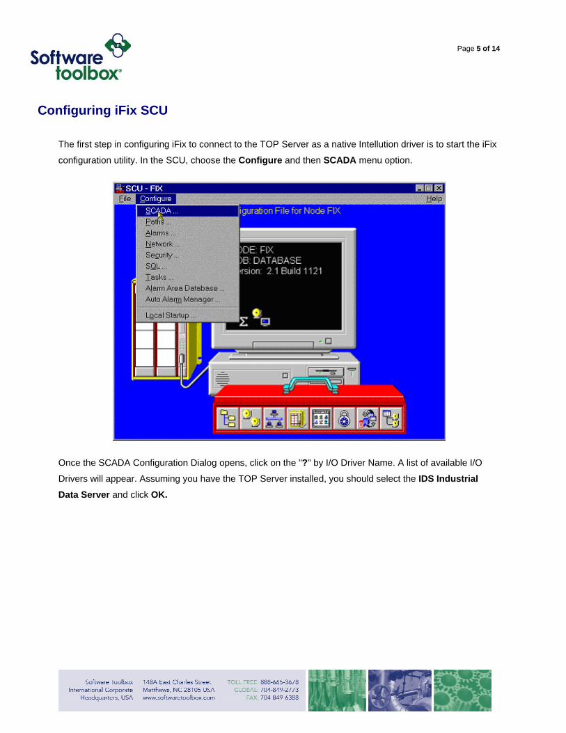
The first step in configuring iFix to connect to the TOP Server as a native Intellution driver is to start the iFix
configuration utility. In the SCU, choose the Configure and then SCADA menu option.
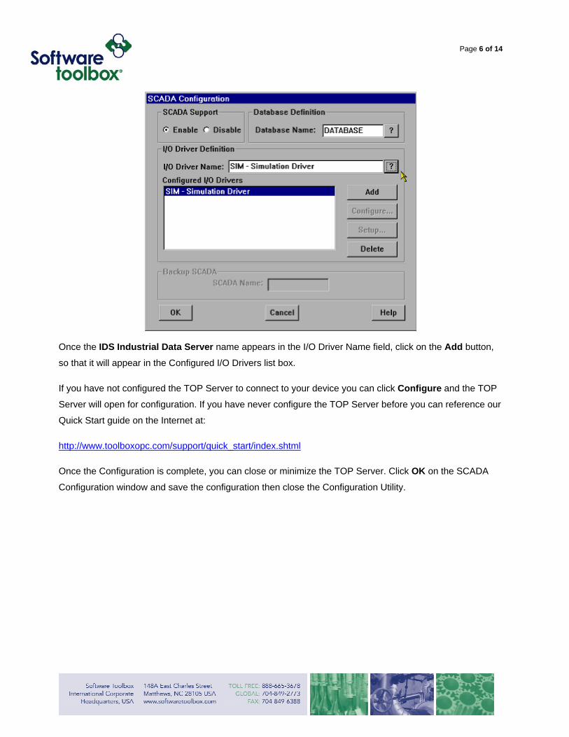
Once the SCADA Configuration Dialog opens, click on the "?" by I/O Driver Name. A list of available I/O
Drivers will appear. Assuming you have the TOP Server installed, you should select the IDS Industrial Data Server and click OK.
Page 6 of 14
Once the IDS Industrial Data Server name appears in the I/O Driver Name field, click on the Add button,
so that it will appear in the Configured I/O Drivers list box.
If you have not configured the TOP Server to connect to your device you can click Configure and the TOP
Server will open for configuration. If you have never configure the TOP Server before you can reference our
Quick Start guide on the Internet at:
http://www.toolboxopc.com/support/quick_start/index.shtml
Once the Configuration is complete, you can close or minimize the TOP Server. Click OK on the SCADA
Configuration window and save the configuration then close the Configuration Utility.
Page 7 of 14
Creating Data-Blocks Inside iFIX Applications
To add server items to iFix Database Manager, you must first complete the following prerequisites:
1) Create and configure the TOP Server with a project adding a channel and a device. Optionally, you can
configure item names (we refer to using item names in the TOP Server as using "static tags").
2) Know the three-letter acronym for the server. For the TOP Server, the acronym is IDS (Industrial Data
Server).
3) Configure the server in iFix SCADA Configuration (look for the acronym IDS).
You do not have to define tag names in the TOP Server in order to use it with Intellution iFix. Our first
example in this tutorial uses tag names that are defined in the TOP Server, but later, we will show you how
to enter device addresses in iFix and pass them straight to the TOP server, a process we call "Dynamic
Tags".
Connecting using tags defined in the TOP Server (Static Tags)
Since the iFix PDB does not support server tag browsing, full path information to tag names in the TOP
Server will be entered into the data-blocks so that the TOP server knows which items you want in the data
block in iFix. When using TOP Server drivers that can import the tag database from programming software
or from the device itself, these project files can be exported from the TOP Server as CSV files that can be
formatted for use in the iFix Database. This method can speed project work and minimize data entry error
on large projects.
To enter driver specifications for a database block in FIX Database Manager
1. Select Add from the Blocks menu in the iFix Database Manager to add a database block. Database
Manager prompts you to select the type of database block.
2. Select the type of block and click OK. The block's dialog box appears as shown below at default (SIM
driver selected)
Page 8 of 14
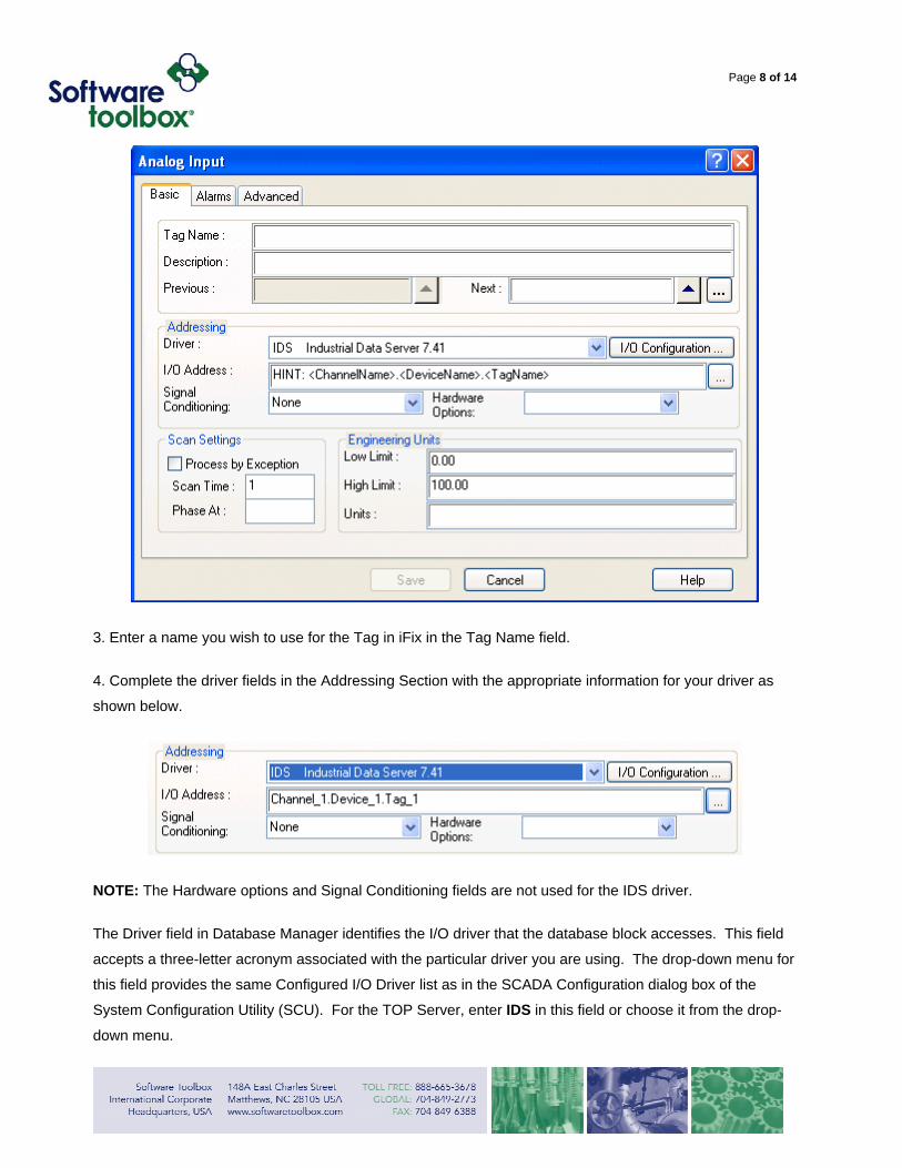
3. Enter a name you wish to use for the Tag in iFix in the Tag Name field.
4. Complete the driver fields in the Addressing Section with the appropriate information for your driver as
shown below.
NOTE: The Hardware options and Signal Conditioning fields are not used for the IDS driver.
The Driver field in Database Manager identifies the I/O driver that the database block accesses. This field
accepts a three-letter acronym associated with the particular driver you are using. The drop-down menu for
this field provides the same Configured I/O Driver list as in the SCADA Configuration dialog box of the
System Configuration Utility (SCU). For the TOP Server, enter IDS in this field or choose it from the drop-
down menu.
Page 9 of 14
The I/O Address for the driver has the following format:
(Channnel_Name.Device_Name.AnyGroup_Names.Tag_Name)
Where:
• Channel Name: is the protocol or driver used in the server project. This name must match the channel
name in the server configuration.
• Device Name: is the PLC or other hardware that the server communicates with. This name must match
the device name for the specified channel in the server configuration
• Tag Name:: is an actual tag name specified in the server
NOTES:
1. You will use IDS for the driver name in iFix regardless of which particular hardware specific TOP server
driver you are using. To iFix, all the drivers look the same.
2. The IDS listing for the TOP Server must appear in iFix's SCU's Configured I/O Driver list box in order for
Database Manager to recognize the acronym you enter – if you have not done this go back to the beginning
of this document and repeat.
Specifying I/O Addresses in Fix Database Manager (Dynamic Tags)
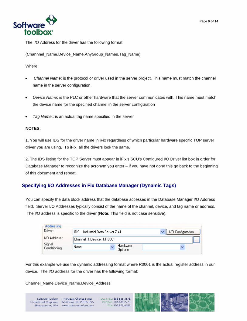
You can specify the data block address that the database accesses in the Database Manager I/O Address
field. Server I/O Addresses typically consist of the name of the channel, device, and tag name or address.
The I/O address is specific to the driver (Note: This field is not case sensitive).
For this example we use the dynamic addressing format where R0001 is the actual register address in our
device. The I/O address for the driver has the following format:
Channel_Name.Device_Name.Device_Address
Page 10 of 14
Where:
• Channel Name: is the protocol or driver used in the server project. This name must match the channel
name in the server configuration.
• Device Name: is the PLC or other hardware that the server communicates with. This name must match
the device name for the specified channel in the server configuration
• Device Address: is an address within the PLC or other hardware device that the server communicates
with
Page 11 of 14
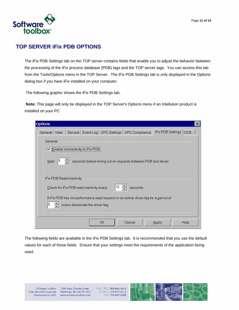
TOP SERVER iFix PDB OPTIONS
The iFix PDB Settings tab on the TOP server contains fields that enable you to adjust the behavior between
the processing of the iFix process database (PDB) tags and the TOP server tags. You can access this tab
from the Tools/Options menu in the TOP Server. The iFix PDB Settings tab is only displayed in the Options
dialog box if you have iFix installed on your computer.
The following graphic shows the iFix PDB Settings tab.
Note: This page will only be displayed in the TOP Server's Options menu if an Intellution product is
installed on your PC
The following fields are available in the iFix PDB Settings tab. It is recommended that you use the default
values for each of these fields. Ensure that your settings meet the requirements of the application being
used.
Page 12 of 14
General Settings
• Enable connectivity iFix PDB: allows you to turn support of the iFix PDB interface On or Off. By
default this setting will be disabled. Important: If iFix PDB operation is turned off (disabled), the server
will not respond to any request for data by iFix PDB. If you intend to use the server only as an OPC
server, you may want to disable Intellution iFix PDB operation. By doing so, you can increase the
security of your data and improve the overall performance of the server.
• Wait xx seconds before timing out on requests between PDB and Driver: represents the amount of
time the iFix PDB will wait for a response from an add/remove/read/write request before timing out. If
the iFix PDB times out, it will fail the request on behalf of the server. This timeout can occur if the
server is busy processing other requests, or if iFix PDB has lost communications with the server. In the
case of lost communications, the iFix PDB will automatically re-establish communications with the
server so that successive timeouts do not occur.
Valid Range Default Range
5 to 60 seconds 5 seconds
iFix PDB Read Inactivity Settings
The server maintains a list of active iFix PDB tags that request data from the server. For each tag in the
list, the server obtains data from the process hardware. The server has as an automatic data reduction
system. The following two fields enable you to efficiently manage the active data, ensuring that only the
necessary data is being updated.
• Check for iFix PDB read inactivity every xx seconds: determines how often the server checks for
inactive data. Based on the value you supply in this field, the server checks any data that the server
determines to be inactive and removes that data item from the list.
Valid Range Default Range
10 to 30 seconds 15 seconds
• xx scans deactivate the tag : establishes the condition by which the server may determine if the data
is active or inactive. Each PDB tag has a scan time attached to it, as defined in the iFix PDB. The
Page 13 of 14
value in this field is multiplied by that scan time to determine if the tag is no longer being read. If the tag
has not been read within the time of this calculated value, the tag is considered to be inactive. When a
tag is considered inactive, the server stops attempting to acquire that data from the device, and the
data is removed on the next inactive scan.
Valid Range Default Value
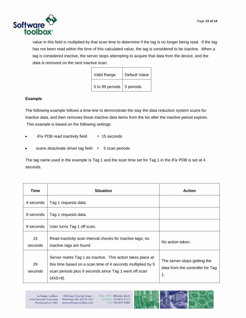
5 to 99 periods 5 periods
Example
The following example follows a time-line to demonstrate the way the data reduction system scans for
inactive data, and then removes those inactive data items from the list after the inactive period expires.
This example is based on the following settings:
• iFix PDB read inactivity field = 15 seconds
• scans deactivate driver tag field = 5 scan periods
The tag name used in the example is Tag 1 and the scan time set for Tag 1 in the iFix PDB is set at 4
seconds.
Time Situation Action
4 seconds Tag 1 requests data.
8 seconds Tag 1 requests data.
9 seconds User turns Tag 1 off scan.
15
seconds
Read inactivity scan interval checks for inactive tags; no
inactive tags are found. No action taken.
29
seconds
Server marks Tag 1 as inactive. This action takes place at
this time based on a scan time of 4 seconds multiplied by 5
scan periods plus 9 seconds since Tag 1 went off scan
(4X5+9).
The server stops getting the
data from the controller for Tag
1.
Page 14 of 14
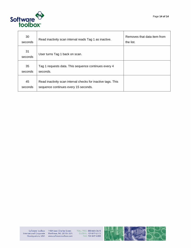
30
seconds Read inactivity scan interval reads Tag 1 as inactive.
Removes that data item from
the list.
31
seconds User turns Tag 1 back on scan.
35
seconds
Tag 1 requests data. This sequence continues every 4
seconds.
45
seconds
Read inactivity scan interval checks for inactive tags. This
sequence continues every 15 seconds.