topic 3 chapter 9 : part 11fkm.utm.my/~mohsin/sme2423/02.gas.power.cycles... · topic 3 topic 3...
TRANSCRIPT

TOPIC 3TOPIC 3 CHAPTER 9 : PART 11CHAPTER 9 : PART 11
BRAYTON CYCLE –THE IDEAL CYCLE FOR GAS
TURBINE
INSPIRING CREATIVE AND INNOVATIVE MINDS

INTRODUCTION
Mohd Kamal Ariffin, FKM, UTM, 20102
A gas turbine is an engine that discharges a fast moving jet of fluid to generate thrust in accordance with Newton's third law of motion. This broad definition of jet engines includes turbojets, turbofans, rockets and ramjets and water jets, but in common usage, the term generally refers to a gas turbine used to produce a jet of high speed exhaust gases for special propulsive purposes.
F-15 Eagle engine is tested at Robins Air Force Base, Georgia, USA
F-15 Eagle is powered by two Pratt & Whitney F100 axial-flow turbofan engines
TOPIC 3 : BRAYTON CYCLE – THE IDEAL CYCLE FOR GAS TURBINE

TYPES OF GAS TURBINE
Mohd Kamal Ariffin, FKM, UTM, 20103
Gas Turbine
TurbopropTurbojet Turbofan
The combustion gasses flow through the nozzle generating 100% thrust and drive a turbine shaft.
Most of the gas pressure drives the turbine. Shaft drives a propeller that creates the majority of the thrust
The gas pressure drives the turbine. Turbine shaft drives an external fan. Both gasses and fan create the thrust
TOPIC 3 : BRAYTON CYCLE – THE IDEAL CYCLE FOR GAS TURBINE

INTRODUCTION
Mohd Kamal Ariffin, FKM, UTM, 20104
Disadvantages of Jet Engines• Compared to a reciprocating engine of the same size, gas turbines are
expensive - because of the high spin and operating temperatures, designing and manufacturing gas turbines is a tough problem
• Gas turbines use more fuel when they are idling, and they prefer a constant rather than a fluctuating load.
Advantages of Gas Turbines• Great power-to-weight ratio compared to reciprocating engines. i.e. the
amount of power you get out of the engine compared to the weight of the engine itself is very good.
• Smaller than their reciprocating counterparts of the same power
So why does the M-1 tank use a 1,500 horsepower gas turbine engine instead of a diesel engine?
TOPIC 3 : BRAYTON CYCLE – THE IDEAL CYCLE FOR GAS TURBINE

Mohd Kamal Ariffin, FKM, UTM, 20105
• Aircraft propulsion system• Electric power generation• Marine vehicle propulsion • Combined-cycle power plant
(with steam power plant)• Tanks
THE USE OF GAS TURBINE
F-15 Eagle
F-15 Eagle
TOPIC 3 : BRAYTON CYCLE – THE IDEAL CYCLE FOR GAS TURBINE

Mohd Kamal Ariffin, FKM, UTM, 20106
THE USE OF GAS TURBINE
Naval Vessel - Iroquois-class destroyers
TOPIC 3 : BRAYTON CYCLE – THE IDEAL CYCLE FOR GAS TURBINE

GAS TURBINE POWER PLANT
Mohd Kamal Ariffin, FKM, UTM, 20107
TOPIC 3 : BRAYTON CYCLE – THE IDEAL CYCLE FOR GAS TURBINE

GAS TURBINE POWER PLANT
Mohd Kamal Ariffin, FKM, UTM, 20108
TOPIC 3 : BRAYTON CYCLE – THE IDEAL CYCLE FOR GAS TURBINE

GAS TURBINE POWER PLANT
Mohd Kamal Ariffin, FKM, UTM, 20109
TOPIC 3 : BRAYTON CYCLE – THE IDEAL CYCLE FOR GAS TURBINE

Mohd Kamal Ariffin, FKM, UTM, 201010
MAJOR POWER PLANTS IN MALAYSIA
Go to list of gasturbine in Malaysia
TOPIC 3 : BRAYTON CYCLE – THE IDEAL CYCLE FOR GAS TURBINE

Mohd Kamal Ariffin, FKM, UTM, 201011
Main Components of Gas Turbine Power Plant
1. Compressor• The compressor sucks in air form the
atmosphere and compresses it to pressures in the range of 15 to 20 bar.
• The compressor consists of a number of rows of blades mounted on a shaft.
• The shaft is connected and rotates along with the main gas turbine.
TOPIC 3 : BRAYTON CYCLE – THE IDEAL CYCLE FOR GAS TURBINE

Mohd Kamal Ariffin, FKM, UTM, 201012
Main Components of Gas Turbine Power Plant
2. Combustor• This is an annular chamber where the fuel burns and is similar to the furnace
in a boiler. • The hot gases in the range of 1400 to 1500 °C leave the chamber with high
energy levels. • The chamber and the subsequent sections are made of special alloys and
designs that can withstand this high temperature
TOPIC 3 : BRAYTON CYCLE – THE IDEAL CYCLE FOR GAS TURBINE

Mohd Kamal Ariffin, FKM, UTM, 201013
Main Components of Gas Turbine Power Plant
3. Turbine• The turbine does the main work of energy conversion. • The turbine portion also consists of rows of blades fixed to the shaft. The
kinetic energy of the hot gases impacting on the blades rotates the blades and the shaft.
• The gas temperature leaving the Turbine is in the range of 500 to 550 °C. • The gas turbine shaft connects to the generator to produce electric power.
TOPIC 3 : BRAYTON CYCLE – THE IDEAL CYCLE FOR GAS TURBINE
Mohd Kamal Ariffin, FKM, UTM, 201014
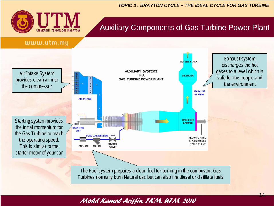
Auxiliary Components of Gas Turbine Power Plant
The Fuel system prepares a clean fuel for burning in the combustor. Gas Turbines normally burn Natural gas but can also fire diesel or distillate fuels
Starting system provides the initial momentum for the Gas Turbine to reach
the operating speed. This is similar to the
starter motor of your car
Air Intake System provides clean air into
the compressor
Exhaust system discharges the hot
gases to a level which is safe for the people and
the environment
TOPIC 3 : BRAYTON CYCLE – THE IDEAL CYCLE FOR GAS TURBINE

How a Gas Turbine Works?
Mohd Kamal Ariffin, FKM, UTM, 201015
• Fresh air at ambient conditions is drawn into the compressor, its temperature and pressure are raised.
• The high-pressure air proceeds into the combustion chamber, the fuel is burned at constant pressure.
• The resulting high-temperature gases then enter the turbine and expand to the atmospheric pressure while producing power.
• The exhaust gases leaving the turbine are thrown out (not re-circulated), causing the cycle to be classified as an open cycle.
TOPIC 3 : BRAYTON CYCLE – THE IDEAL CYCLE FOR GAS TURBINE

Mohd Kamal Ariffin, FKM, UTM, 2010
The actual cycle :• Difficult to analyze due to the presence of complicating effects, such as friction.• The working fluid remains a gas throughout the entire cycle, involves chemical
analysis, causes more complicated analysis.• The working fluid does not undergo a complete thermodynamic cycle, it is
thrown out at the end of the cycle (as exhaust gases) instead of being returned to the initial state.
• Working on an open cycle.
Air Standard Cycle
Why?
TOPIC 3 : BRAYTON CYCLE – THE IDEAL CYCLE FOR GAS TURBINE

Mohd Kamal Ariffin, FKM, UTM, 2010
The Air Standard Assumptions
1. The working fluid is air, continuously circulates in a closed loop and behaves as an ideal gas.
2. All processes are internally reversible.3. The combustion process is replaced by a heat-addition process from an
external source.4. The exhaust gas is replaced by a heat-rejection process that restores the
working fluid to its initial state.5. Air has constant specific heats whose values are determined at room
temperature, 300 K. This assumption is called coldcold--airair--standard assumptionstandard assumption
r1
r2
1
2
k1k
1
2
1
2
PP
PPheatspecific Variable
PP
TT isentropic For
=→
⎟⎟⎠
⎞⎜⎜⎝
⎛=→
−
TOPIC 3 : BRAYTON CYCLE – THE IDEAL CYCLE FOR GAS TURBINE

Mohd Kamal Ariffin, FKM, UTM, 201018
• The compression and expansion processes remain the same
• The combustion process is replaced by a constant-pressure heat-addition from an external source
• The exhaust process is replaced by a constant- pressure heat-rejection process to the ambient air.
• The ideal cycle that the working fluid undergoes this closed loop is the BraytonBrayton cyclecycle.
ACTUAL VS BRAYTON CYCLE
TOPIC 3 : BRAYTON CYCLE – THE IDEAL CYCLE FOR GAS TURBINE
Mohd Kamal Ariffin, FKM, UTM, 201019
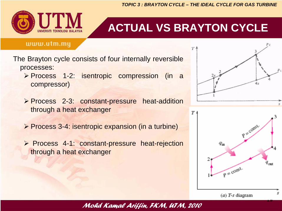
The Brayton cycle consists of four internally reversible processes:
Process 1-2: isentropic compression (in a compressor)
Process 2-3: constant-pressure heat-addition through a heat exchanger
Process 3-4: isentropic expansion (in a turbine)
Process 4-1: constant-pressure heat-rejection through a heat exchanger
ACTUAL VS BRAYTON CYCLE
TOPIC 3 : BRAYTON CYCLE – THE IDEAL CYCLE FOR GAS TURBINE

Mohd Kamal Ariffin, FKM, UTM, 201020
BRAYTON CYCLE – THE ANALYSIS
• All 4 processes of the Brayton cycle are executed in steady flow devices, thus, they should be analyzed as steady-flow processes.
• By neglecting the changes in kinetic and potential energies, the energy balance for a steady-flow process can be expressed, on a unit mass basis, as:
( ) ( ) ( )inletexitpinletexitoutinoutin TTchhwwqqhwq
−=−=−+−
=−∑∑ Δ
TOPIC 3 : BRAYTON CYCLE – THE IDEAL CYCLE FOR GAS TURBINE

Mohd Kamal Ariffin, FKM, UTM, 201021
( )( )( )( )12p1212com
43p4334tur
14p1441out
23p2323in
TTchhwwTTchhw w
TTchhq qTTchhq q
−=−==
−=−==
−=−==
−=−==
The energy balance for each process of the Brayton cycle can be expressed, on a unit mass basis, as:
BRAYTON CYCLE – THE ANALYSIS
TOPIC 3 : BRAYTON CYCLE – THE IDEAL CYCLE FOR GAS TURBINE

Mohd Kamal Ariffin, FKM, UTM, 201022
( )( )
( )( )23
14
23p
14p
in
out
in
outin
in
netth TT
TT1TTcTTc
1qq1
qqq
qw
−−
−=−
−−=−=
−==η
The first-law of thermodynamic states that, for a closed system undergoing a cycle, the net work output is equal to net heat input i.e. wnet = qin - qout
For isentropic processes, 1-2 and 3-4
( )1432
4
3k1k
4
3k1k
1
2
1
2
PP and PP
TT
PP
PP
TT
==⇒
=⎟⎟⎠
⎞⎜⎜⎝
⎛=⎟⎟
⎠
⎞⎜⎜⎝
⎛=
−−
Since P2 = P3 and P4 = P1 , thus
ratio pressurerpp
pp
p4
3
1
2 ===
BRAYTON CYCLE – THE ANALYSIS
TOPIC 3 : BRAYTON CYCLE – THE IDEAL CYCLE FOR GAS TURBINE

( )( ) 2
1th
2
1
2
32
1
41
23
14
TT1 Thus,
TT
1TTT
1TTT
TTTT
−=⇒=
⎟⎟⎠
⎞⎜⎜⎝
⎛−
⎟⎟⎠
⎞⎜⎜⎝
⎛−
=−−
η
Mohd Kamal Ariffin, FKM, UTM, 201023
k1k
p43k
1k
p12 rTT and rTT−−
==
Substituting into the thermal efficiency equation,
( )( )
( )( ) ( )( ) ( ) k/1k
pk/1k
p1k/1k
p4
14
23
14th r
11rTrT
TTTTTT1 −−− −=
−−
=−−
−=η
Also,
Note: Only valid for ideal Brayton cycle – under the cold air-standard assumptions
Thus,
TOPIC 3 : BRAYTON CYCLE – THE IDEAL CYCLE FOR GAS TURBINE
Mohd Kamal Ariffin, FKM, UTM, 201024
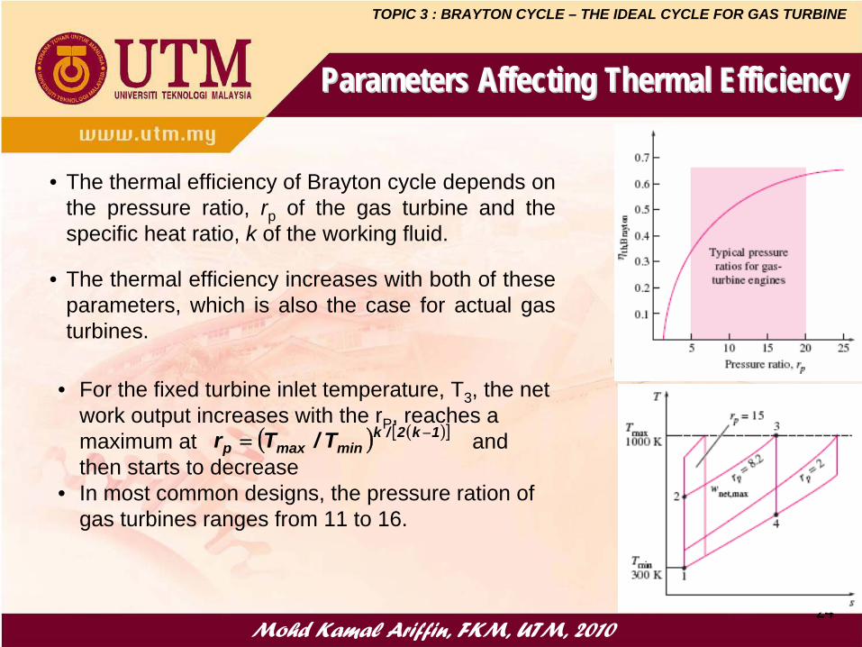
• The thermal efficiency of Brayton cycle depends on the pressure ratio, rp of the gas turbine and the specific heat ratio, k of the working fluid.
• The thermal efficiency increases with both of these parameters, which is also the case for actual gas turbines.
Parameters Affecting Thermal EfficiencyParameters Affecting Thermal Efficiency
• For the fixed turbine inlet temperature, T3 , the net work output increases with the rP , reaches a maximum at and then starts to decrease
• In most common designs, the pressure ration of gas turbines ranges from 11 to 16.
( ) ( )[ ]1k2/kminmaxp T/Tr −=
TOPIC 3 : BRAYTON CYCLE – THE IDEAL CYCLE FOR GAS TURBINE

Mohd Kamal Ariffin, FKM, UTM, 201025
WORK RATIO
( ) ( )( )
( )( )43
12
43p
12p43p
34
1234
turbine
netw TT
TT-1TTc
TTcTTcw
www
wr−−
=−
−−−=
−==
Work Ratio, rw (air-standard assumptions) is defined as
We know that,k
1k
p
34k
1k
p12r
TT and r.TT −
−==
k1k
p3
1
k1k
p3
k1k
pk1k
p1
k1k
p
3
k1k
p1
w
r.TT1
1rT
r.1rT1
r
11T
1rT1r
−
−
−−
−
−
−=
⎟⎠⎞
⎜⎝⎛ −
⎟⎠⎞
⎜⎝⎛ −
−=
⎟⎟⎟
⎠
⎞
⎜⎜⎜
⎝
⎛−
⎟⎠⎞
⎜⎝⎛ −
−=
Therefore,
TOPIC 3 : BRAYTON CYCLE – THE IDEAL CYCLE FOR GAS TURBINE

Mohd Kamal Ariffin, FKM, UTM, 201026
• BWR is defined as the ratio of compressor work to the turbine work
( )( )
k1k
p3
1
43p
12p
34
12
turbine
compbw
rTT
TTcTTc
ww
ww
r
−
⎟⎟⎠
⎞⎜⎜⎝
⎛=
−
−===
BACK WORK RATIO
• The BWR in gas turbine power plant is very high, normally one-half of turbine work output is used to drive the compressor
• Thus required a larger turbine
TOPIC 3 : BRAYTON CYCLE – THE IDEAL CYCLE FOR GAS TURBINE

Mohd Kamal Ariffin, FKM, UTM, 201027
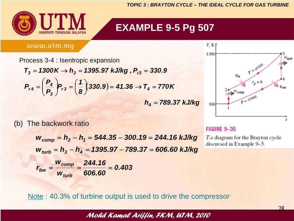
EXAMPLE 9-5 Pg 507
A gas turbine power plant operating on an ideal Brayton cycle has a pressure ratio of 8. The gas temperature is 300 K at the compressor inlet and 1300 K at the turbine inlet. Utilizing the air-standard assumptions, determine (a) the gas temperature at the exits of the compressor and the turbine (b) the back work ratio and (c) the thermal efficiency.
Assumptions : Steady operating conditions, kinetic and potential energy changes are negligibleAnalysis : The variation od specific heats with temperature is to be considered
a) The air temperature at the compressor and turbine exits are determined from isentropic relations
( )( )
kJ/kg 35.544h
K540T09.11386.18PPPP
386.1P , kJ/kg 19.300h K300T
2
21r1
22r
r111
=
=→==⎟⎟⎠
⎞⎜⎜⎝
⎛=
==→=
Process 1-2 : Isentropic compression
TOPIC 3 : BRAYTON CYCLE – THE IDEAL CYCLE FOR GAS TURBINE
Mohd Kamal Ariffin, FKM, UTM, 201028
EXAMPLE 9-5 Pg 507
( )
kJ/kg 37.789h
K770T36.419.33081P
PPP
9.330P , kJ/kg 97.1395h K1300T
4
43r3
44r
r333
=
=→=⎟⎠⎞
⎜⎝⎛=⎟⎟
⎠
⎞⎜⎜⎝
⎛=
==→=Process 3-4 : Isentropic expansion
kJ/kg 60.60637.78997.1395hhwkJ/kg16.24419.30035.544hhw
43turb
12comp
=−=−=
=−=−=
403.060.60616.244
ww
rturb
compbw ===
Note : 40.3% of turbine output is used to drive the compressor
(b) The backwork ratio
TOPIC 3 : BRAYTON CYCLE – THE IDEAL CYCLE FOR GAS TURBINE

Mohd Kamal Ariffin, FKM, UTM, 201029
EXAMPLE 9-5 Pg 507
(c) The thermal efficiency
kJ/kg 4.36216.24460.606wwwkJ/kg62.85135.54497.1395hhqq
compturbnet
2323in
=−=−==−=−==
42.6% or 426.062.85140.362
qw
in
netth ===η
TOPIC 3 : BRAYTON CYCLE – THE IDEAL CYCLE FOR GAS TURBINE

Mohd Kamal Ariffin, FKM, UTM, 201030
DEVIATION OF ACTUAL GAS TURBINE FROM IDEALIZED ONES
The differences between actual gas turbine and ideal Brayton cycle :• Pressure drop during the heat-addition and heat
rejection processes• Larger actual work input to the compressor• The actual work output from the turbine is less
because of irriversibilities
1a2
1s2
a
sc hh
hhww
−−
==η
s43
a43
s
aT hh
hhww
−−
==η
Isentropic efficiency of compressor
Isentropic efficiency of turbine
TOPIC 3 : BRAYTON CYCLE – THE IDEAL CYCLE FOR GAS TURBINE

Mohd Kamal Ariffin, FKM, UTM, 201031
EXAMPLE 9-6 Pg 509
a) The back work ratio
( )( ) kJ/k 61.51560.60685.0ww
kJ/kg 20.30580.0
16.244ww
sTturb
c
scomp
===
===
ηη
59.2% or 592.061.51520.305
ww
rturb
compbw ===
Assuming a compressor efficiency of 80 percent and a turbine efficiency of 85 percent, determine (a) the back ratio (b) the thermal efficiency (c) the turbine exit temperature of the gas turbine cycle discussed in Example 9-5.
TOPIC 3 : BRAYTON CYCLE – THE IDEAL CYCLE FOR GAS TURBINE

Mohd Kamal Ariffin, FKM, UTM, 201032
EXAMPLE 9-6 Pg 509
b) The thermal efficiency
( )17-A TableKT and . ..
whh hhhw
2a
compa
aacomp
→==+=
+=
⇒−=
598396052030519300
12
212
kJ/kg 41.21020.30561.515wwwkJ/kg 58.79039.60597.1395hhq
compturbnet
a23in
=−=−==−=−=
26.6% or 266.058.79041.210
qw
in
netth ===η
TOPIC 3 : BRAYTON CYCLE – THE IDEAL CYCLE FOR GAS TURBINE
Mohd Kamal Ariffin, FKM, UTM, 201033
EXAMPLE 9-6 Pg 509
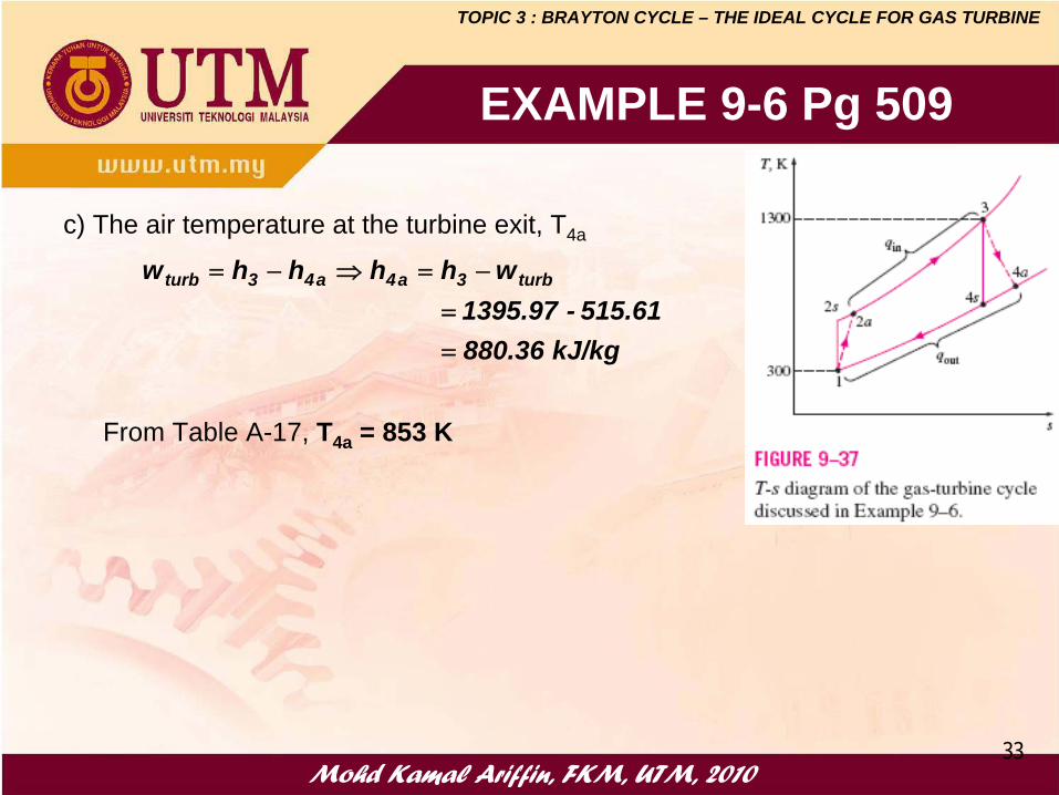
c) The air temperature at the turbine exit, T4a
kJ/kg 880.36 515.61-1395.97
whhhhw turb3a4a43turb
==
−=⇒−=
From Table A-17, T4a = 853 K
TOPIC 3 : BRAYTON CYCLE – THE IDEAL CYCLE FOR GAS TURBINE

Mohd Kamal Ariffin, FKM, UTM, 201034
99––89/90 (page 540) 89/90 (page 540) Air enters the compressor of a gas-turbine engine at 300 K and 100 kPa, where it is compressed to 700 kPa and 580 K. Heat is transferred to air in the amount of 950 kJ/kg before it enters the turbine. For a turbine efficiency of 86 percent, determine:
(a) the fraction of turbine work output used to drive the compressor,(b) the thermal efficiency.
Assume:(a) variable specific heats for air.(b) constant specific heats at 300 K.
ASSIGNMENT 5
TOPIC 3 : BRAYTON CYCLE – THE IDEAL CYCLE FOR GAS TURBINE

Mohd Kamal Ariffin, FKM, UTM, 201035
The early gas turbines (1940s to 1959s) found only limited use despite their versatility and their ability to burn a variety of fuels, because its thermal efficiency was only about 17%. Efforts to improve the cycle efficiency are concentrated in three areas:
1. Increasing the turbine inlet (or firing) temperatures.The turbine inlet temperatures have increased steadily from about 540°C (1000°F) in the 1940s to 1425°C (2600°F) and even higher today.
2. Increasing the efficiencies of turbo-machinery components (turbines, compressors).The advent of computers and advanced techniques for computer-aided design made it possible to design these components aerodynamically with minimal losses.
3. Adding modifications to the basic cycle (inter-cooling, regeneration or recuperation, and reheating).The simple-cycle efficiencies of early gas turbines were practically doubled by incorporating inter-cooling, regeneration (or recuperation), and reheating.
IMPROVEMENTS OF GAS TURBINE’S PERFORMANCE
TOPIC 3 : BRAYTON CYCLE – THE IDEAL CYCLE FOR GAS TURBINE

Mohd Kamal Ariffin, FKM, UTM, 201036
BRAYTON CYCLE WITH REGENERATION
• Temperature of the exhaust gas is higher than the temperature of the air leaving the compressor.
• The air leaving the compressor can be pre-heated by the hot exhaust gases in a counter-flow heat exchanger (a regenerator or recuperator) – a process called regeneration.
• The thermal efficiency of the Brayton cycle increases due to regeneration since less fuel is used for the same work output.
Note: The use of a regenerator is recommended only when the turbine exhaust temperature is higher than the compressor exit temperature.
TOPIC 3 : BRAYTON CYCLE – THE IDEAL CYCLE FOR GAS TURBINE

Mohd Kamal Ariffin, FKM, UTM, 2010
37
Effectiveness of the regenerator,
Effectiveness under cold-air standard assumptions,
Thermal efficiency under cold-air standard assumptions,
Effectiveness of the RegeneratorAssuming the regenerator is well insulated and changes in kinetic and potential energies are negligible, the actual and maximum heat transfers from the exhaust gases to the air can be expressed as
BRAYTON CYCLE WITH REGENERATION
242'5max,regen
25act,regen
hhhhqhhq
−=−=
−=
24
25
max,regen
act,regen
hhhh
−−
==ε
24
25
TTTT
−−
=ε
( )( ) k/1kp
3
1regen,th r
TT1 −
⎟⎟⎠
⎞⎜⎜⎝
⎛−=η
Note : If ε = 100%, qregen,act = qregen,max
TOPIC 3 : BRAYTON CYCLE – THE IDEAL CYCLE FOR GAS TURBINE

Mohd Kamal Ariffin, FKM, UTM, 201038
EXAMPLE 9-7 Pg 512
Note : ηth has gone up from 26.6% to 36.9%
TOPIC 3 : BRAYTON CYCLE – THE IDEAL CYCLE FOR GAS TURBINE

Mohd Kamal Ariffin, FKM, UTM, 201039
Prob. 9-110 Pg 542
Air enters the compressor of a regenerative gas turbine engine at 310 K and 100 kPa, where it is compressed to 900 kPa and 650 K. The generator has an effectiveness of 80 percent and the air enters the turbine at 1400 K. For a turbine efficiency of 90 percent, determine:
a) The amount of heat transfer in the generatorb) The thermal efficiencyc) Assume variable specifics heats for air.
Answer : 193 kJ/kg , 40.0%
TOPIC 3 : BRAYTON CYCLE – THE IDEAL CYCLE FOR GAS TURBINE

Mohd Kamal Ariffin, FKM, UTM, 201040
72.0hhhh
2a4
25 =−−
=ε
86.0hhhh
s43
a43T =
−−
=η
1
24s
3
4a5
6
T
s
310
650
1400
P3 = 900 kPa
P1 = 100 kPa
25gen hhq −=
in
compturb
in
netth q
wwq
w −==η
TOPIC 3 : BRAYTON CYCLE – THE IDEAL CYCLE FOR GAS TURBINE
Prob. 9-110 Pg 542

Mohd Kamal Ariffin, FKM, UTM, 201041
BRAYTON CYCLE WITH INTERCOOLING, REHEATING, & REGENERATION
The net work output of a gas-turbine cycle can be increased by either:
a) decreasing the compressor work, or b) increasing the turbine work, orc) both.
The compressor work input can be decreased by carrying out the compression process in stages and cooling the gas in between, using multistage compression with intercooling.
The work output of a turbine can be increased by expanding the gas in stages and reheating it in between, utilizing a multistage expansion with reheating.
TOPIC 3 : BRAYTON CYCLE – THE IDEAL CYCLE FOR GAS TURBINE

Mohd Kamal Ariffin, FKM, UTM, 201042
Physical arrangement of an ideal two-stage gas-turbine cycle with intercooling, reheating, and regeneration
BRAYTON CYCLE WITH INTERCOOLING, REHEATING, & REGENERATION
TOPIC 3 : BRAYTON CYCLE – THE IDEAL CYCLE FOR GAS TURBINE

Mohd Kamal Ariffin, FKM, UTM, 201043
The work input to a two-stage compressor is minimized when equal pressure ratios are maintained across each stage. This procedure also maximizes the turbine work output.Thus, for best performance,
Conditions for Best Performance
• Intercooling and reheating always decreases thermal efficiency unless are accompanied by regeneration.
• Therefore, intercooling and reheating are always used in conjunction with regeneration.
BRAYTON CYCLE WITH INTERCOOLING, REHEATING, & REGENERATION
9
8
7
6
3
4
1
2
PP
PP and
PP
PP
==
TOPIC 3 : BRAYTON CYCLE – THE IDEAL CYCLE FOR GAS TURBINE

Mohd Kamal Ariffin, FKM, UTM, 201044
EXAMPLE 9-8 Pg 515
TOPIC 3 : BRAYTON CYCLE – THE IDEAL CYCLE FOR GAS TURBINE

Mohd Kamal Ariffin, FKM, UTM, 201045
EXAMPLE 9-8 Pg 515
TOPIC 3 : BRAYTON CYCLE – THE IDEAL CYCLE FOR GAS TURBINE

Mohd Kamal Ariffin, FKM, UTM, 201046
EXAMPLE 9-8 Pg 515
TOPIC 3 : BRAYTON CYCLE – THE IDEAL CYCLE FOR GAS TURBINE

Mohd Kamal Ariffin, FKM, UTM, 201047
EXAMPLE 9-8 Pg 515
TOPIC 3 : BRAYTON CYCLE – THE IDEAL CYCLE FOR GAS TURBINE

Mohd Kamal Ariffin, FKM, UTM, 201048
Consider an ideal gas-turbine cycle with two stages of compression and two stages of expansion. The pressure ratio across each stage of the compressor and turbine is 3. The air enters each stage of the compressor at 300 K and each stage of the turbine at 1200 K. Determine:
a) the back work ratio, andb) the thermal efficiency of the cycle
assuming: 1. no regenerator is used, and2. a regenerator with 75 percent effectiveness is used. Use a variable specific heats assumption.
Prob. 9–121 (page 543)
TOPIC 3 : BRAYTON CYCLE – THE IDEAL CYCLE FOR GAS TURBINE

Mohd Kamal Ariffin, FKM, UTM, 201049
Prob. 9–124 (page 556)
1
2
6
5 7
8
T
s
3
4
300
1200
1
2
6
5 7
8
T
s
3
4
300
1200
9
10
3PP
PP
PP
PP
8
7
6
5
3
4
1
2 ====
TOPIC 3 : BRAYTON CYCLE – THE IDEAL CYCLE FOR GAS TURBINE

Mohd Kamal Ariffin, FKM, UTM, 201050
Q1 FINAL EXAM APRIL 2010

Mohd Kamal Ariffin, FKM, UTM, 201051
Q1 FINAL EXAM APRIL 2010
1
2s4s
3
4a
T
s
2a5
6
310
1200
85.0hhhh
s43
a43T =
−−
=η
80.0hhhh
1a2
1s2C =
−−
=η
70.0hhhh
a2a4
a25 =−−
=ε
TOPIC 3 : BRAYTON CYCLE – THE IDEAL CYCLE FOR GAS TURBINE

Mohd Kamal Ariffin, FKM, UTM, 2010
Two-Stage Expansion
1
2
4s
3
4a
5s
T
s
5a
LP,turbnet
HP,turbcomp
wwww
=
=
TOPIC 3 : BRAYTON CYCLE – THE IDEAL CYCLE FOR GAS TURBINE

Mohd Kamal Ariffin, FKM, UTM, 2010
Two-Stage Compression, Two-stage expansion
TOPIC 3 : BRAYTON CYCLE – THE IDEAL CYCLE FOR GAS TURBINE

Mohd Kamal Ariffin, FKM, UTM, 2010
THE END