topic1-2 the vapor-compression cycle
TRANSCRIPT

Topic1-2 The Vapor-Compression Cycle
The vapor-compression cycle: the most widely used refrigeration in practice
Carnot cycle: the highest efficiency cycle
Net work
1-2 Adiabatic compression
Heat to low-Temp. sink
Heat from high-Temp. source
Tem
per
atu
re, K
1
2 3
4
1
2 3
4
Work
Compressor
2-3 Isothermal addition of heat
3-4 Adiabatic expansion4-1 Isothermal rejection of heat
Work
Turbine? ?
Entropy, kJ/kgK
Carnot cycle: an ideal-Standard of comparison- Guide of T to max eff.
1

1. Carnot Refrigeration cycle
2
Carnot cycle: thermodynamically reversible processes
Net work
2
1-2 Adiabatic compression
Heat from low-Temp. source
Heat to high-Temp. sink
Tem
per
atu
re, K
Entropy, kJ/kgK
1
23
4
1
23
4WorkCompressor
2-3 Isothermal rejection of heat
3-4 Adiabatic expansion4-1 Isothermal addition of heat
Work
Turbine
1-2 Adiabatic reversible compression = isentropic compression
3-4 Adiabatic reversible expansion = isentropic expansion

Refrigeration
2. Coefficient of performance (COP)
3
Efficiency = Output / Input → Heat Engine = Wout/Qin
Net work
3
Tem
per
atu
re, K
Entropy, kJ/kgK
1
23
4
reversible process: qrev = ∫Tds :
Refrigeration cycle: input = net workOutput = q2-3 – wasteDesired output = q4-1 – useful refrigeration
HE = (TH - TL)/ TH
TH
TL
Coefficient of performanceCOP = desired output/input
COPRefrigeration Carnot
= T1(s1 – s4)/[(T2 – T1)(s1 – s4)]= T1 / (T2 – T1)= TL / (TH - TL)
s1 = s2s3 = s4

3. Conditions for highest COP
low T2 → high COP
4
COPR Carnot = T1 / (T2 – T1)
Refrigeration
4
Net work
4
Tem
pe
ratu
re, K
Entropy, kJ/kgK
1
23
4
T2
T1
s1 = s2s3 = s4high T1 → high COP
T1 → more effect upon COP than T2
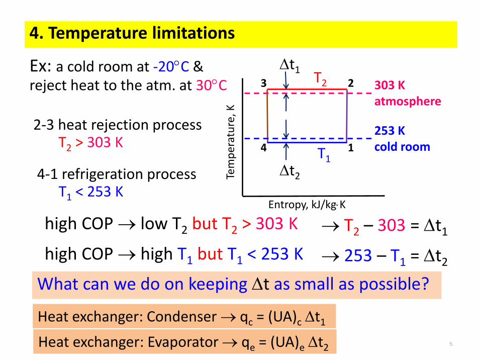
4. Temperature limitations
Ex: a cold room at -20C & reject heat to the atm. at 30C
5
Tem
per
atu
re, K
Entropy, kJ/kgK
1
23
4
T2
T1
253 K cold room
303 K atmosphere
2-3 heat rejection processT2 > 303 K
4-1 refrigeration processT1 < 253 K
high COP → low T2 but T2 > 303 K
high COP → high T1 but T1 < 253 K
→ T2 – 303 = t1
→ 253 – T1 = t2
t1
t2
What can we do on keeping t as small as possible?
Heat exchanger: Condenser → qc = (UA)c t1
Heat exchanger: Evaporator → qe = (UA)e t2

5. Carnot heat pump
Heat pump: same equipment as a refrigeration system- delivering heat at high Temp.
6
Coefficient of performanceCOP = desired output/input
Net workTe
mp
era
ture
, K
Entropy, kJ/kgK
1
23
4Heat rejected
COPHeat Pump Carnot = T2 / (T2 – T1) = COPR + 1Performance factor = COPR + 1
Performance factor- vary from 1 to
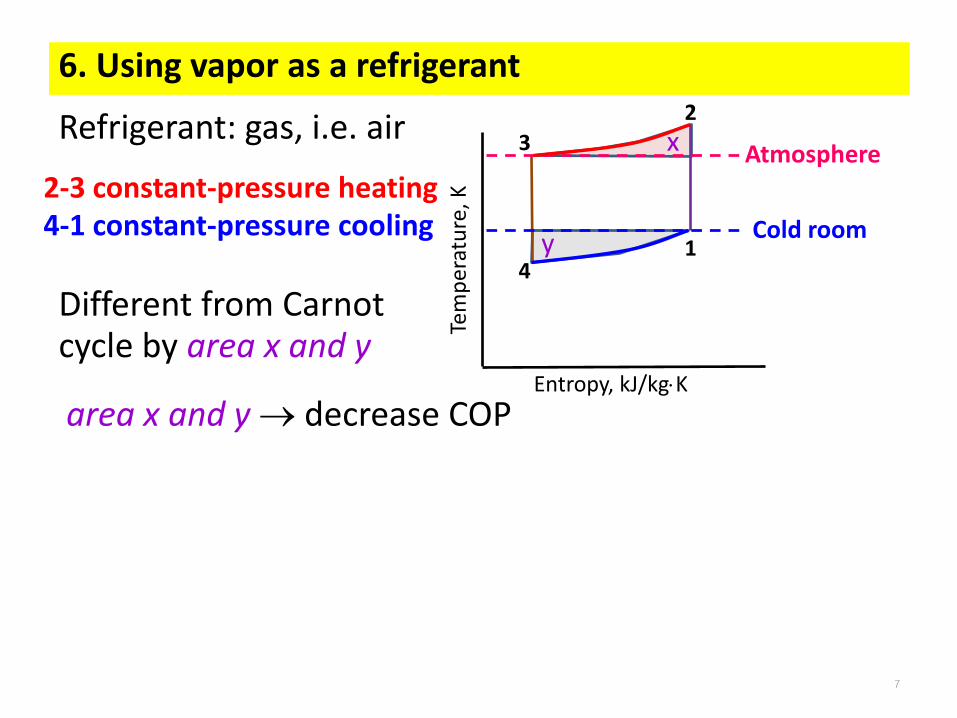
6. Using vapor as a refrigerant
Refrigerant: gas, i.e. air
7
Tem
per
atu
re, K
Entropy, kJ/kgK
1
2
3
4
x
Cold room
Atmosphere
y
2-3 constant-pressure heating4-1 constant-pressure cooling
Different from Carnot cycle by area x and y
area x and y → decrease COP
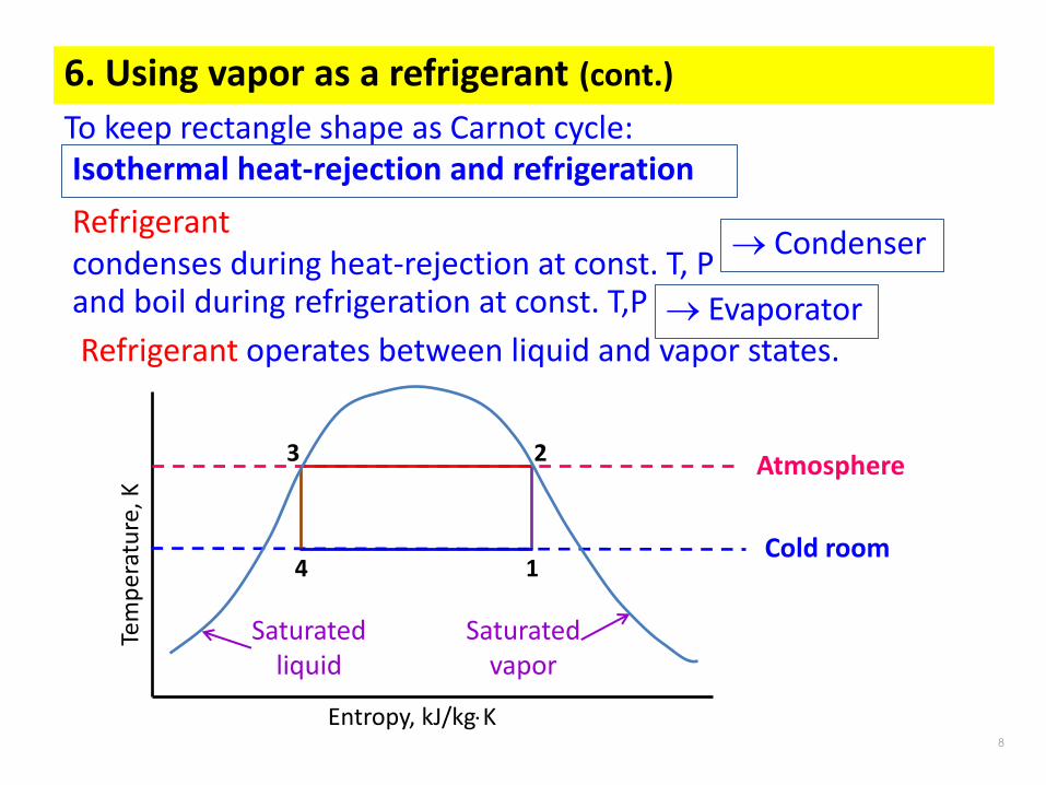
6. Using vapor as a refrigerant (cont.)
8
To keep rectangle shape as Carnot cycle:
Refrigerant condenses during heat-rejection at const. T, Pand boil during refrigeration at const. T,P
Isothermal heat-rejection and refrigeration
→ Condenser
→ EvaporatorRefrigerant operates between liquid and vapor states.
Tem
per
atu
re, K
Entropy, kJ/kgK
Cold room
Atmosphere
1
23
4
Saturated liquid
Saturated vapor

7. Wet compression versus dry compression
Wet compressionLiquid refrigerant may damage valves or cylinder head.Droplets of liquid may wash the lubricating oil from cylinder wall
9
Tem
per
atu
re, K
Entropy, kJ/kgK
Superheat horn
1
2
3
4
Dry compressionSuperheat horn – more work required for dry compression

8. Expansion process Constant-enthalpy throttling -- Isenthalpic process
10
Tem
per
atu
re, K
Entropy, kJ/kgK
1
2
3
4
Expansion engine: 1. Small work compared to compression work2. Difficulties of lubrication intrude when a fluid of two-phase drives the engine3. Not economic for work done compared to cost of expansion engine
Throttling device: reducing pressure by valve or other restriction

9. Properties of refrigerants : low boiling point
11
Pre
ssu
re,
kPa
Enthalpy, kJ/kg
Critical point
t = constant
Saturated liquid
Saturated vapor
Mollier (Pressure-enthalpy) diagram of a Refrigerant

12
1
23
4
Isobaric
Isobaric
Net work
Refrigeration effectTe
mp
erat
ure
, K
Entropy, kJ/kgK
1
23
4
T2
T1
Carnot refrigeration cycle
high T1, low T2 → high COP
COPR Carnot = T1 / (T2 – T1)
T1 → more effect on COP than T2
12

10. Standard vapor-compression cycle
13
Tem
per
atu
re, K
Entropy, kJ/kgK
1
2
3
4
Process 1-2: Isentropic compression of saturated vapour in compressor Process 2-3: Isobaric heat rejection in condenser Process 3-4: Isenthalpic expansion of saturated liquid in expansion device Process 4-1: Isobaric heat extraction in the evaporator
Pre
ssu
re,
kPa
Enthalpy, kJ/kg
1
23
4
Condensation
Exp
ansi
on
Evaporation
Isen
thal
pic
Isobaric
Isobaric
Carnot refrigeration cycle

The standard vapor-compression cycle
14
Mollier (Pressure-enthalpy) diagram
Pre
ssu
re,
kPa
Enthalpy, kJ/kg
1
23
4
Condensation
Exp
ansi
on
Evaporation
1
2
3
4
PowerQc
Qe
Power= w(h2-h1)Qe = w(h1-h4)
Qc = w(h2-h3)

11. Performance of the standard vapor-compression cycle
15
Pre
ssu
re,
kPa
1
23
4
Condensation
Exp
ansi
on
Evaporation
Enthalpy, kJ/kg
Work of compression = wc = h2 – h1
Heat rejection rate = qc = h2 – h3
Refrigeration effect = qe = h1 – h4
COP = qe/wc
Volume flow rateper kW of refrigeration = wvsuc /Qe
Power per kW of refrigeration = P/Qe = 1/COP

Example 10-1 A standard vapor-compression cycle developing 50 kW of refrigeration using refrigerant 22 operates with a condensing temperature of 35C and an evaporating temperature of -10C. Calculate (a) the refrigerating effect in kilojoules per kilogram, (b) the circulation rate of refrigerant in kilograms per second, (c) the power required by the compressor in kilowatts, (d) the coefficient of performance, (e) the volume flow rate measured at the compressor suction, (f) the power per kilowatts of refrigerant, and (g) the compressor discharge temperature.
Data: VCC, Qe, R22, tcond, tevap
Assume: standard VCC; isentropic compression, isobaric, isenthalpic processes
Method: evaporator, energy balance, (a) qe = h1-h4
evaporator, mass balance, (b) w = Qe/qe
compressor, energy balance, (c) Pcomp = w(h1-h2)(d) COP = Qe/Pcomp
(e) Vsuc = wvsat vapor@pevap, pevap= psat@tevap
(f) P/Qe = 1/COP(g) tdischarge = t@(pcond, s2=s1), pcond= psat@tcond
Pre
ssu
re,
kPa
1
23
4
Enthalpy, kJ/kg
35C= tcond
-10C= tevap
(a)qe (b)w (c) Pcomp (d) COP (e)vsuc (f)P/Qe (g)tdischarge
16

17
-10 C = tevap
35 C= tcond
1
2
h1=402 h2=435h4=243
T2=57C
3
4
17
Calculation: (a) qe = h1-h4
(b) w = Qe/qe
(c) Pcomp = w(h1-h2)(d) COP = Qe/Pcomp
(e) Vsuc = wvg@pevap
(f) P/Qe = 1/COP(g) tdischarge = t@(pcond, s2=s1)
h@0 C =200 kJ/kg
Example 10-1 VCC R22 at 35C and -10C

p-h diagram R717
18
80 kPa = Psuction
1000 kPa = Pdischarge
1
3
h1=1410 h3=1800h@0 C =200 kJ/kg
h6=316
Example VCC ammonia at 80 kPa to 1000 kPa

12. Liquid Subcool Heat exchanger (LSHX)
19
Subcool liquid from condenser with suction gas from evaporator
Heat balance: h3-h4 = h1-h6
Refrigerating effect: h6-h5 = h1-h3
qe = h6-h5
19

13. Actual vapor-compression cycle
20
Discharge line: gas, p is a penalty on compressor power
Liquid line: liquid, smaller diameter, more p → liquid flashes in to vapor →expansion device will not work properly
Suction line: gas, p is a penalty on efficiency, reduce pi to comp.

Exam10-2 ระบบท ำควำมเยน็แบบอดัไอใช้ R22 มอุีณหภมูทิี่ Evaporator Te = 0C และที่Condenser Tc = 40C ใหห้ำ a) sketch เสน้ refrigeration cycle บน p-h diagram, b) COP ของ Carnot cycle, c) Refrigeration effect, 2d) Work of compression, e) อุณหภมูขิอง discharge, f) COP ของ standard vapor-compression refrigeration cycle, g) ถำ้น ำ Liquid-to-suction heat exchanger มำใชเ้พือ่ superheating เพิม่ 10C และ subcool คำ่อุณหภมูทิีข่ำออก Condenser เป็นเทำ่ใด, h) ถำ้เพิม่ อุณหภมูิ Evaporator Te เป็น 10C โดยทีป่รมิำตร suction เทำ่เดมิ จะไดอ้ตัรำกำรไหลเชงิมวล เพิม่ขึน้หรอืลดลง เพรำะData: VCC, R22, te, tc ,
Assume: standard VCC; isentropic compression, isobaric, isenthalpic processes
Method: (b) COPcarnot = T1 / (T2 – T1)=6.825CV evaporator, energy balance, (c) qe = h1-h4
CV compressor, energy balance, (d) w = (h1-h2)(e) tdischarge =(f) COP = qe/wc=5.85
CV liq-to-suc HE, energy balance, h3-h3’ = h1’-h1
(g)tsp = 10C, t3’= 40-5.5C(h) te w
Pre
ssu
re,
kPa
1
23
4
Enthalpy, kJ/kg
3’
1’
(a)p-h (b) COPcarnot (c) qe (d) wc (e)tdis (f)COP (g) t3’ (h) w
40C= tcond
0C= tevap
21

22
0 C = tevap
40 C= tcond
1
2
h1=405 h2=432h4=250
T2=60C
3
4
s1=s2=1.752
1’
3’

high T1, low T2 → high COP
23
COPR Carnot = T1 / (T2 – T1)
Refrigeration
23
Net work
23
Tem
pe
ratu
re, K
Entropy, kJ/kgK
1
23
4
T2
T1
s1 = s2s3 = s4
T1 → more effect on COP than T2
14.1 Analysis of Carnot refrigeration cycle
T1
T2

2424
14.2 Comparison between Carnot & standard VCRS
COPStandard VCRS =COP = qe / wcomp = (h1 – h4)/(h2 – h1)
R = COPStandard VCRS / COPR Carnot
COP = (hg@Te – hf@Tc)/(hs1=s2 – hg@Te)
COP asTevap
or Tsuction
COP as Tcond
25
1
23
4
Isen
thal
pic
Isobaric
Isobaric
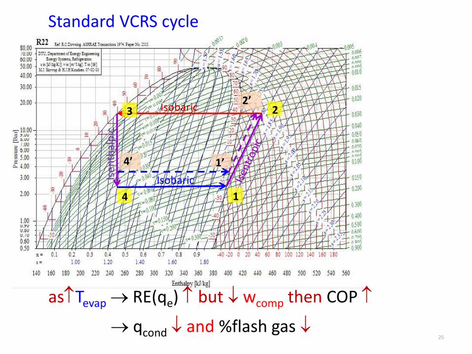
Standard VCRS cycle
asTevap → RE(qe) but wcomp then COP
→ qcond and %flash gas
1’
2’
4’
25

Refrigeration effect
Net work
Refrigeration effect
26
Tem
per
atu
re, K
Entropy, kJ/kgK
1
23
4
Carnot refrigeration cycle
Tem
per
atu
re, K
Entropy, kJ/kgK
Standard VCRS cycle
1
2
3
4
T2
T1
Irreversibility due to 1) non-isothermal heat rejection (process 2-3) 2) isenthalpic throttling (process 3-4)
Throttling loss
Superheat horn
Superheat horn – more work required for dry compression
Throttling loss - flash gas, reduction in refrigeration effect and increase more work because irreversibility
qewc
14.2 Comparison between Carnot & standard VCRS
Good for heat pumps
wc

27
14.3 Subcooling and superheating
1
23
4 1’
2’3’
4’
Superheating by heat -transfer from cold room →qe
-exchange with pipeline → loss-transfer from subcool liquid → -→wc in R717 but not in R22→Tdischarge affects lubrication→ Dry vapor to prevents entry of liquid droplets into compressor
cold room Subcooling by heat transfer to
surrounding or to suction vapor→qe by reduce throttling loss→ Reduce flash gas → lower
pressure drop in evaporator- ensures that only liquid enters into throttling device leading to its efficient operation.
atmosphere

14.4 Actual vapor-compression refrigeration cycle
28
Irreversibility due to 1. Pressure drops in evaporator, condenser and LSHX 2. Pressure drop across suction and discharge valves of the compressor 3. Heat transfer in compressor 4. Pressure drop and heat transfer in connecting pipe lines
4-1d → pressure drop in evaporator1d-1c → Superheat of vapor in evaporator 1c-1b → Useless superheat in suction line
1b-1a → Suction line pressure drop 1a-1 → Pressure drop across suction valve
1-2 → Non-isentropic compression 2-2a → Pressure drop across discharge valve
2a-2b → Pressure drop in the delivery line
2b-2c → Desuperheating of vapor in delivery pipe
2b-3 → Pressure drop in the condenser
3-3a → Subcooling of liquid refrigerant
3a-3b → Heat gain in liquid line
Actual systems differ from standard cycles -- foreign matter such as lubricating oil, water, air, particulate matter→ pressure drop, heat transfer coefficient in evaporator

29
1
2
3
4
4-1d → pressure drop in evaporator
1d-1c → Superheat of vapor in evaporator
1c-1b → Useless superheat in suction line
1b-1a → Suction line pressure drop
1a-1 → Pressure drop across suction valve
1-2 → Non-isentropic compression
2-2a → Pressure drop across discharge valve
2a-2b → Pressure drop in the delivery line
2b-2c → Desuperheating of vapor in delivery pipe
2b-3 → Pressure drop in the condenser
3-3a → Subcooling of liquid refrigerant
3a-3b → Heat gain in liquid line

30
Discharge line: vapor line
Liquid line: liquid
Suction line: vapor line
Standard cycle
14.4 Actual vapor-compression refrigeration cycle
2-2a → Pressure drop across discharge valve
2a-2b → Pressure drop in the delivery line
→wc (compressor work)→ Tdischarge – compressor life
1a-1 → Pressure drop across suction valve
1-2 → Non-isentropic compression
suction pressure (ps) →specific volume → compressor volumetric efficiency (v)→wc
→wc
→ liquid flashes into vapor qewc
→ expansion device will not work properly
4-1d → pressure drop in evaporator
1d-1c → Superheat of vapor in evaporator
1c-1b → Useless superheat in suction line 1b-1a → Suction line pressure drop
3-3a → Subcooling of liquid refrigerant
3a-3b → Heat gain in liquid line
→ efficient operation→ qe
2b-2c → Desuperheating of vapor in delivery pipe
2b-3 → Pressure drop in the condenser
→wc but smaller than that in vapor line
need cooling
Pipe design for small pdrop
Reduce pdrop by velocity flow or pipe size→ heat transfer coefficient in evaporator*minimum velocity is required to carry lubricating oil back to compressor