topics in cement and gypsum research - jos brouwers · topics in cement and gypsum research cement,...
TRANSCRIPT

H.J.H. Brouwers Topics in cement and gypsum research Cement, lime and calcium sulphate based materials, most importantly concrete, are by far the mostly produced man-made materials. The annual production in 2007 of several materials read as follows: Timber 4 billion ton Plastics and rubber 250 million ton Steel 1.2 billion ton Gypsum 250 million ton Lime 130 million ton Cement 2.6 billion ton Concrete/mortar 14 billion ton One can see the huge quantities in which the building materials lime, gypsum and concrete are produced. Though these materials are produced from non-renewable mineral resources, these are some of the world's most abundant ones. They are also relatively maintenance-free. Possibly poisonous coatings, which may leach to the environment need not be applied, nor their regular removal (using hazardous and dangerous materials) and re-application. Furthermore, their products possess a long lifetime. So they remain relatively long in the building life cycle, which can even be lengthened by building adaptable and/or transportable and/or easily dismantled objects. When a functional re-use of structure or structural parts is not possible anymore, then after demolition and crushing, the broken material may enter another building life cycle. Cement, lime and gypsum are also useful binders to render contaminated sludge/soil and industrial and nuclear wastes less harmful to the environment. This enables safe storage or landfill; in some case even a useful building material is obtained. Another possibility is adding function to the materials, that render them multifunctional, smart, etc. An example is adding phase changing materials (PCMs), photo catalytic TiO2 etc.
A large stream of the above materials comprises by-products that substitute the primary raw materials/products. For instance blast furnace slag and fly ash can substitute clinker, flue gas desulfurization gypsum. Some annual quantities of generated by-products and their present use (as % of total) as substitute read Fly ash 1.2 billion ton (45%) Blast furnace slag 120 million ton (75%) FD Gypsum 50 million ton (100%) Silica fume 0.3 million ton (100%) In what follows research topics will be addressed that are motivated by the considerations given above:

0.8
1
1.2
1.4
1.6
1.8
2
0 20 40 60 80 100Slag proportion (mass%)
C/S
rat
io in
C-S
-H
Prediction
Measurement
• Cement hydration; • Self-Compacting Concrete; • Earth-moist concrete; • Self-cleaning/air purifying concrete; • Durability of concrete • Gypsum (plasterboard) technology
In order to reach the set goals, the leitmotiv in all researches (the so-called “research approach”) comprises mineral oxide engineering and particle size engineering. Next these topics are discussed in more detail. Microstructure development Knowledge of microstructure development is necessary for the development of cement and calcium sulphate recipes (“mineral oxide engineering”) and assessing the macroscopic properties of minerally bound products.
The first step in this hydration research concerned the reactions and numerical simulation of ordinary Portland cement (OPC). Based on the water retention data provided by Powers and Brownyard (1948), the hydration reactions of the five major clinker phases (C3S, C2S, C3A, C4AF and CS ) and their hydration products were quantified (Brouwers (2004, 2005). For the numerical simulation of the hydration reactions and the pore water composition, a 3-D simulation model (CEMHYD3D) from NIST was adopted and extended (Van Eijk (2001), Brouwers and Van Eijk (2003)). The next step in the research comprised the inclusion of slags and hemi-hydrates in the hydration model. Slag-blended cement hydration A reaction model for blended cement containing various amounts of slag is established based on stoichiometric calculations, which are valid for alkali-activated slag as well (Chen and Brouwers (2007a, 2007b), Chen (2007)). The model correlates the compositions of the unhydrated slag-blended cement, i.e. the mineral compositions of the slag and Portland cement clinker, and their blending proportions, with the quantities and compositions of the hydration products.
Figure 1 Predicted and measured C/S ratio in C-S-H versus slag proportions in blended cement (experimental data from Richardson and Groves (1992), ratio of the slag/clinker hydration degrees is 0.7, w/b = 0.4).

The model is validated with measurements in a series of experiments investigating slag-blended cements with various ingredients. The predicted composition of the main hydration product, C-S-H is compared with the measured values in experiments, and good agreement is observed (Figure 1).
The microstructure development of the hydrating slag cement paste is also simulated with the theoretical model. The volume fractions of products in the paste after 1 year hydration with different slag proportions are presented in Figure 2. C-S-H can be seen to be the dominant phase in the paste in volume for all slag proportions. Its fraction is approximately constant, about 40 percent of the paste. The volume fraction of ettringite (AFt) is approximately constant as well. A remarkable reduction of the CH fraction is observed with increasing slag proportions.
Figure 2 Volume fraction of products in hydrating slag cement paste versus slag proportions (w/b = 0.4, assuming all clinker and 70 percent of slag has reacted).
The reaction model for slag-blended cement reaction is incorporated into the 3-D computer model CEMHYD3D (Chen (2007)). The types of reaction products, their quantities and properties can be computed for the conditions that govern their hydration state (such as relative humidity and temperature). Factors influencing the microstructure development are investigated with the computer model, including: (1) the composition and PSD of Portland cement and gypsum (if present), (2) the composition and PSD of slag (3) proportion of slag in the paste, (4) water/binder ratio, (5) curing condition and (6) the slag reactivity. Some properties of the microstructure, such as porosity, CH content and the composition of the main hydration product (C-S-H) are predicted (Chen (2007), Chen et al. (2007), Chen and Brouwers (2008)). Hemi-hydrates Recently, CEMHYD3D has been extended with several additional possibilities which enable the hydration of particles smaller than 1 µm and the hydration of hemi-hydrates to gypsum (as ultimate product), designated as multi-scale and multi-time features. Multi-scale gives the user the possibility to investigate the hydration of a cement- or gypsum-based material at several different ‘system resolutions’. The system resolution determines the smallest particle size in the system. The system resolution is important for digitized hydration model, because particles smaller than the voxel size cannot be represented. So
0
20
40
60
80
100
0 25 50 75 100Slag proportion (mass%)
Vol
ume
fract
ion
(%)
Cap. PoreSlagCHHGAFtMonocAHHTC-S-H
Slag proportion (mass%)
Volu
me
frac
tion
(%)
Cap. Pore Slag CH HG AFt Monoc AH HT C-S-H
Slag proportion (mass%)
Volu
me
frac
tion
(%)

higher system resolution will lead to more reliable results, but on the other hand a higher system resolution will lead to increase of needed computation time. Therefore a balance between reliability and computation time needs to be found. Due to better computation possibilities, the use of higher resolutions is possible nowadays. The original model had a system resolution of 1 µm. The new version of CEMHYD3D can run with a system resolution of 0.25 µm.
In the original model the system resolution had considerable effect on the simulation results. This is mainly due to the lack of considerations of the diffusion-controlled reactions in the model. A new concept ‘hydration layer’ was been incorporated for mitigating the effects of system resolution on the model predictions (Chen and Brouwers (2008)). The performed simulations with different system resolutions showed the robustness of the improved model is demonstrated. Comparisons of model predictions with experimental measurements further demonstrate that the use of hydration layer can successfully mitigate the bias brought by the system resolution. The time conversion factor appears to be appropriate for simulation the hydration of a wide range of cements and independent of the system resolution in the improved model. The model is also applied to the hydration and fire behaviour of gypsum plasterboards. As the starting material for the gypsum plasterboard production, hemihydrate occurs in two formations of α- and β-type, which differ in particle size and shape, application characteristics, and the preparation method (Wirsching (2005)). β-hemihydrate is mainly used to produce gypsum plasterboard since the hydration product of the α-hemihydrate is too brittle to be used as building material (Wirsching (2005)).
Hemihydrate takes place hydration reaction immediately after mixing with water according to a through-solution route, first the hemihydrate dissolves and then the dihydrate precipitates from the solution shown as equation (1). The key variable within the precipitation process is the super-saturation. A solution saturated with respect to hemihydrate is always supersaturated with respect to gypsum. But the condition of supersaturation is not sufficient cause for a system to begin crystallizing (Mullin (1972)). Before crystals can grow a number of minute solid objects must exist. These minute solid objects are called seeds, embryos or nuclei, which is necessary for the growth into crystals of visible size. The crystal growth of gypsum has normally a needle form and can be described by spiral growth theory which is based on a particular mode of dislocation of the crystalline, the screw dislocation. A screw dislocation forms when the atoms are displaced along a dislocation line, rather that at right angles to it as in the case of the edge dislocation. The attachment of growth units to the face of the dislocation results in the development of a spiral growth pattern over the crystal face (Mullin (1972)). Therefore the hydration model is modified in order to have possibility to use the gypsum as main product. Because the hydration time of hemi-hydrates is very short compared to hydration of cement, the cycle-time relation has to be shortened. Therefore CEMHYD3D is extended with the option of multi-time modelling. Multi-time is comparable with multi-scale modelling. The idea behind multi-time is the variation of the length of the time steps in the model. In order to describe this variation, the multi-time factor k is introduced. A lower multi-time factor results in smaller time steps during hydration and therefore resulting in more cycles. Multi-time modelling introduces two major adaptations to the model: the modification of the reaction kinetics and a correction of the calculation of the reaction time.

Within CEMHYD3D the kinetics are mainly regulated by the dissolution and nucleation chances and the number of diffusion steps. Due to smaller time step at lower multi-scale factor k, the number of particles that dissolve, diffuse and nucleate is smaller. Therefore these probabilities need to be smaller. The modification of the dissolution probability is done by multiplying by the standard dissolution probabilities (PD,1) with the correction factor χ. This factor will take in account conditional probability. Conditional probability is needed, because of interdependence between the cycles. Conditional probability takes in account that a pixel can only dissolve in the second cycle when it had not dissolved in the first cycle. The second condition is that the number of particle that dissolves in one complete cycle should be equal as after two times a half cycle. Nucleation is modified in the same way as the dissolution chance.
In the present model 500 random diffusion steps (D1) are undertaken. After every diffusion step, there is a possibility for nucleation. When it is assumed that a pixel can walk in 1 cycle over a distance x and multi-time modelling will not change the speed of a pixel then in multi-time situation after 1/k cycles the same distance x should be travelled. This is only possible when the distance for each multi-time cycle is equal to k·x and therefore the number of diffusion steps is equal to k·D1. The second modification is the calculation of the time associated to one cycle. The calculation of the time within CEMHYD3D is based on Knudsen model2. The multi-time modification influences both the number of cycles and the reaction rate. Since the reaction rate depends on the temperature and the reactions (dissolution and nucleation) in the model direct influence the temperature. No modification is needed here. The number of cycles needs to be modified. The number of old cycles can calculated from the number of new cycles.
Based on the modification described, an analysis of the use of multi-time is assessed. For the parameters used for these simulations are shown in Table 1. The dissolution of hemihydrate for multi-time factors k ≤ 1 shows a very small difference between the dissolution lines. The same conclusion is valid for the nucleation of dihydrate from diffusion hemihydrate pixels. The close fit for dissolution and nucleation results in a close fit of the reaction degree for the different multi-time factors (Figure 3). Parameter Value Unit Water/solid factor
1.1
β 0.0038 Hour/cycle2
PD 0.1 PN 0.01 imax 9000 Eact 40 kJ/mol Initial temperature
20 °C
Table 1: Used parameters for simulation
0
0.1
0.2
0.3
0.4
0.5
0.6
0.7
0.8
0.9
1
0 0.05 0.1 0.15 0.2 0.25
Time [Houres]
Rea
ctio
n de
gree
[V/V
]
k=.1 k=.25 k=.50
k=1.00 k=2.00
Figure 3: Reaction degree for different multi-time factors

Self-Compacting Concrete The development of Self-Compacting Concrete (SCC), also referred to as “Self-Consolidating Concrete”, has recently been one of the most important developments in the building industry. The incentive for the first development of this concrete in Japan came from high-fluidity anti-washout underwater concretes developed in Germany during the 1970’s (Nagataki (1998)).
Ever since the pioneering work by Féret (1892) it is known that the particle size distribution of the aggregates governs the workability and hardened properties of concrete mixes. The so-called Japanese Method makes use of the packed densities of gravel and sand individually, whereas in the Chinese Method the packing of these aggregates is considered integrally (Brouwers and Radix (2005)). Brouwers and Radix (2005) subsequently applied the packing theory by Plum (1950) to all solids, i.e. aggregates and powders (cement and filler), in the concrete. This is an approach that was actually recommended already by Fuller and Thompson (1907, pp. 242-244). This has resulted in self-compacting concretes with low cement contents that met all technical requirements. The cement efficiency was found to be 0.14 N/mm2 per kg/m3.
The research focuses on the environmental performance (e.g. of mineral waste fillers), as well as on the widening of the size range of the solids; the upper particle size is increased from 16 to 32 mm, and the water demand of the powders. Increasing the size range of the mix and designing mixes that follow the Plum packing model, grading line will result in further improvements. It will be seen that the design method allows the reduction of the cement content, and with 32 mm aggregate a cement efficiency of 0.22 N/mm2 per kg/m3 is already achieved. A new design concept for SCC The consideration of the aggregate grading is a fundamental factor for the development of concrete mix designs. So-called standard sieve lines were essential elements in most of the concrete design regulations so far. But within these standards only the coarser aggregates have been considered concerning their aggregate size. Starting from a minimum aggregate size of 0.25 mm different proportions of aggregate fractions were specified up to the maximum particle size. The whole range of grading curves was cut into areas for favourable, useable and unfavourable mixes. However, smaller particles were not taken into account. With the acceptance of the standard EN 206 in the year 2000 these grading curves have been omitted.
In the field of Self-Compacting and High-Performance Concrete a lot of research has been performed with the focus on grading and particle packing. The Linear Packing Density Model (LPDM), the Solid Suspension Model (SSM) and the Compressive Packing Model (CPM) as a representative of the so-called third generation of packing models are well known examples for packing models (De Larrard and Sedran (1994)). For the most part the amount of solids was even cut into coarse and fine sections and optimized separately concerning their packing. A couple of research projects were focused on dense packing of cement pastes. An integral approach based on the particle size distribution of all

contained compounds, however, can hardly be found. This led to the development of a mix design based on an alternative approach of particle packing. Development of a theoretical model Based on the work of Brouwers and Radix (2005) the particle size distribution of all solids is believed to have the strongest influence on the particle packing beside the particle shape when looking for continuously graded granular blends. Like above mentioned there are different ways of modeling particle size distributions. A practicable solution for the reproduction of natural continuously graded grains is represented by the distribution function from Plum (1950), which can be expressed as follows:
qmin
qmax
qmin
q
DDDD)D(P−−
= (1)
where P(D) is the cumulative finer fraction, D is the particle size of the considered fraction, Dmin is the minimum particle size and Dmax is the maximum particle size in the mix. The exponent q is referred to as distribution modulus and allows controlling the amount of fines for a generated mix in a certain range. While higher values of q (typically from 0.25 to 0.5) lead to coarser blends, a lower q will produce mixes with high amounts of fines. A further advantage of this distribution function is the introduction of a minimum particle size. Common functions like the Fuller parabola (where q is set to 0.5) only considers the maximum particle size and the grading of aggregates only, that leading to amounts of fines that in fact do not necessarily exist in the actual mix. Then again, the Plum grading starts first with quantities of fines, which are effectively present, and thus giving in total more fines. By Brouwers (2006) it is proven mathematically that, depending on the sieve width ratios employed (e.g. 2 or √2), a q of about 0.28 results in optimum packing. Furthermore, an analytical expression was derived for the void fraction of a packing that follows eq. (3). Based on various dry packing tests with tailored grading curves, indeed values in the range from 0.25 up to 0.35 were found for best packing. High amounts of fines, compared to standard concrete, are characteristic for the Japanese Design Method for SCC. These fines are required to ensure sufficient flowability of the fresh concrete. Most of the time this high fineness of SCC mixes was realized with cement, which led to higher material costs and a stronger environmental impact.
Considering the ideas of the new mix design model, a high percentage of these fines can be substituted by other powder materials. Using for this purpose industrial waste products like ashes or process residues like natural stone wastes will have a beneficial effect on the environmental performance of concrete, whereby at the same time material costs will be lowered. Assuming that optimum packing is obtained the void fraction becomes minimized. This means less voids have to be filled with paste (reduction of required paste amount) and on a smaller scale less void volume has to be filled with water. Conversely, it can be concluded that more water is available for lubrication. However, not only the packing fraction plays a role, also the total specific surface of all solids governs the fluidity of a

mix. Having these considerations in mind, a design model based on the above mentioned packing model is developed.
0
10
20
30
40
50
60
70
80
90
100
0.01 0.1 1 10 100 1000 10000 100000
Particle Size [micron]
% C
umul
ativ
e Fi
ner [
V/V]
Target Function Composed Mix CEM I 52,5N Marble Powder G-1Sand 0-1 Sand 0-4 Gravel 2-8 Gravel 4-16
Figure 4 PSD of a mix (dashed line) composed with the help of the new design concept. The target function (solid line) as well as the PSDs of all applied materials are given too (measured with Malvern 2000 and a √2 sieve set). With the help of linear optimization a fit of a granular blend, containing all solids going to be used, is made according to the defined distribution function. That means that the proportions of the selected materials are changed as long as the least deviation from the target curve is obtained. This deviation is determined using a least squares method, which is described in detail by Hüsken and Brouwers (2008), Hunger and Brouwers (2008) and Hunger (2009). In Figure 4 an example of a composed mix (dashed line) in comparison with the target function (solid line) is given. For the design of the target function the model automatically will take the Dmin and Dmax over from the selected materials. The used distribution modulus amounts to q = 0.22. For the purpose of comparison the PSDs of all contained materials are given too. Results Using both, the new design concept based on the particle grading and the information given by the determination of the water demands, various SCC mixes have been produced and tested for their fresh and hardened concrete properties. The analysis of this information shows a promising way of designing new kinds of SCC with improved qualities in regard

to their workability, mechanical properties and durability. A profound further increase of the cement efficiency to values of 0.19 - 0.22 N/mm2 per kg/m3 is obtained.
Table 2 Mix proportions of the mix from Figure 4.
Another basic observation concerns the application of the water/cement ratio. Up to now the strength was given as a function of the water/cement ratio, the cement content and type of cement (it must be understood that there are also other influences). In applying the new design tool, unconventionally low cement contents (200 to 280 kg/m3) were selected, the water/cement ratio therefore sometimes considerably exceeded the mark of 0.60. Considering the limits given for different exposure classes in the standards, this might be a handicap. Note that with these high water/cement ratios, no high total water contents are obtained. In evaluating the data gathered in the framework of these test series no distinct correlation between water/cement ratio and strength properties could be derived. Creating different states of packing with equal water/cement ratios, a broad margin of strength values was obtained and contrary equal strength was achieved with different water/cement ratios. Relating, however, strength to water/powder ratios (w/p) a clear linear correlation could be found (all particles smaller than 125 μm are counted as powder). The data in Figure 5 show that for a certain amount of powder in a mix, the lowest possible water content should be found by means of grading optimization (with compliance of requested workability).
Figure 5 furthermore learns that mixes clearly different from the derived fit all contain cement loads notably different from 270 kg/m3. This asks so to say for a correction by the used cement amount. Based on this a reliable prediction of the strength to be expected after 28 days is possible, which reads as follows:
cemcomp,cube,c m3616.0pw568.0f ⎟⎟
⎠
⎞⎜⎜⎝
⎛+−= (2)
Focusing on the achieved compressive strength data, it can be noticed that the general level is high, knowing that a SCC was produced using a cement type CEM III/B 42,5N and aggregate sizes up to 32 mm (for most of the mixes). As filler material limestone powder, fly ash and stone waste powders (granite and marble) were employed. The majority of strength measurements amounted to values in the range of 50 up to 60 N/mm2 which is
Material Volume (m3) Mass (kg) Cement CEM I 52.5 N 65.3 200.0 Marble powder 140.7 394.1 Sand 0-1 (fine river sand) 59.2 156.0 Sand 0-4 (river sand) 253.4 669.6 Gravel 2-8 152.5 399.5 Gravel 4-16 125.9 328.0 Water 191.0 191.0 Admixture (Glenium 51) 2.5 2.74 Air 12.0 Total 1,000.0 2,338.2

remarkable considering the fact that for most mixes only 270 kg of a slag cement or even less was used.
Com
pres
sive
stre
ngth
f c,cube
[N/m
m2 ]
Figure 5 Relation between the compressive strength after 28 days and the w/p ratio. Another interesting aspect is the application of these bigger aggregates in SCC. Normally, maximum aggregate sizes of 8 – 16 mm or rarely 22 mm are applied for SCC. Given that with increasing aggregate size especially the durability properties are affected, a loss of durability qualities was expected for these kinds of concrete. But the packing influence by the “particle size engineering” showed a much stronger effect. Hunger (2009) has proven that self-compacting concrete mixes attain a packing density that is situated between the random close and random loose packing density. Finally, SCC mixes have been produced with q = 0.22 having a better durability performance than SCCs designed with Dmax = 16 mm. As an example in Figure 6 the capillary water absorption as a simple indirect durability parameter of these SCCs is given compared with the improved mixes containing 32 mm aggregates. The analysis of this data resulted in sorptivity indices of about 2 mm/h0.5 for the three given mixes.
A further green development is the direct application of micro-encapsulated phase change materials (PCM) to enhance the thermal properties of concrete and SCC in particular. Using the above explained design tool, SCC are designed which contain different amounts of PCM for the purpose of studying the influences on thermal properties. PCM in concrete can have an effect in many ways. It can (i) lower the heat development during hydration and therefore prevent thermal stresses and cracking. Moreover, (ii) when the transition temperature is selected closely above the freezing point, the number of freeze-thaw cycles can be decreased, which appears to be an interesting application for e.g. bridge deck concrete. Finally, (iii) the PCM can buffer heat and cold peaks in order to obtain a more stabilized indoor climate without using heating and cooling devices (to a

certain extent), when the transition temperature of the PCM is selected close to the preferred indoor temperature. The research done so far indicates that this can all be fulfilled.
0.0
0.2
0.4
0.6
0.8
1.0
1.2
1.4
1.6
0 2 4 6 8 10 12 14
Time [h0,5]
Gai
n of
mas
s [%
]
Mix F Mix L Mix CMix A Mix B Mix C
Figure 6 Capillary water absorption of three different mixes (F = fly ash, L = limestone, C = only cement as powder) composed using Dmax = 32 mm, compared with 3 SCC mixes with Dmax = 16 mm (A, B and C from Brouwers and Radix (2005)).
0
1000
2000
3000
4000
5000
6000
7000
8000
19 20 21 22 23 24 25 26 27 28
Temperature [oC]
Ther
mal
mas
s [J/
K]
0% PCM1% PCM3% PCM5% PCM
Figure 7 Thermal mass of the PCM mixes versus temperature

As an example Figure 7 refers to the increased thermal mass of different concrete mixes containing PCM. However, the lacking stability of the encapsulation has turned out to be problematic and results in a notable strength loss with increasing PCM content. This problem is going to be solved by more resilient encapsulation (mechanically as well as chemically), which is one pursuit of the relevant industry now. Earth-moist concrete In the cast concrete products industry (such as paving blocks, slabs, curbs, roof tiles and sewage pipes), zero-slump, or also so-called earth-moist concrete (EMC), is applied for the mass production of these products. These concrete mixes are dry with a very stiff consistency, so they are rammed in the rigid mould, and after dense compaction, stripping from the mold can take place almost immediately so that short processing times with high quantities can be achieved.
Although EMC mixes are used on large scale for the mass production of the aforementioned earth-moist concrete products, the applied methods for designing mixes are strongly geared to procedures and standards for standard concrete. Nevertheless, the regulations that apply to these products allow innovations such as cement reduction, application of stone sludge waste, a higher and tailor-made aggregate content, etc. In particular, the reduction and substitution of expensive primary filler materials (cement) by secondary stone waste materials is of vital importance for the cost reduction.
y = 3.633x - 245.6R2 = 0.94
y = 5.565x - 373.9R2 = 0.73
0
10
20
30
40
50
60
70
80
90
100
65 70 75 80 85
Packing Density P [V.-%]
Com
pres
sive
Str
engt
h f c,cube [N
/mm
2 ] 310 kg cement per m³325 kg cement per m³ (mix)
Figure 8 Compressive strength versus packing density for tested preliminary mixes with cement content of 310 kg and 325 kg per m3 concrete, respectively. Some first positive results regarding cement reduction and the application of stone waste material could be achieved on lab scale by using novel mix design concept for designing EMC mixes. The results of the laboratory investigations and a detailed explanation of the mix design concept are reported by Hüsken and Brouwers (2008).

Figure 8 demonstrates how improved and denser packing of the granular concrete ingredients is influencing the strength of the hardened concrete.
The particle packing can either be improved by higher compaction efforts, which implies usually the use of higher forces and is resulting in more resistant machines and therefore cost intensive investments, or the right composition of the raw materials considering the granulometric properties of all ingredients which can be done in a cost efficient way when the EMC mix is designed. Not only the mechanical properties are influenced by an optimized particle packing but also the workability of the fresh concrete can be improved. In the past, relatively little attention has been paid to the early-age behavior of EMC mixes as the poor workability causes problems when the concrete is handled under laboratory conditions. Sufficient and to the production process comparable degrees of compaction can hardly be achieved under laboratory conditions by using standard test methods for ordinary concrete but a high degree of compaction is necessary to achieve sufficient strength values immediately after demolding the fresh concrete products. Capillary forces between the finer particles combined with the inner friction of the mix provide the required early strength of the concrete. This strength in the early-age is also called green strength. In soil mechanics this phenomenon is referred to as apparent cohesion, which can only be activated in partially saturated fine sands or sandy soils. Here, the content of fines as well as the fineness of the smaller particles and the degree of saturation influences the capillary forces. The same principles are also determining the properties of EMC based concrete products directly after their compaction. A thorough study on EMC with some investigations on the early-age behavior of EMC is presented by Bornemann (2005). Furthermore, work carried out by Juvas (1996) focus on the workability of EMC mixes using the intensive compaction test (IC-tester). The results presented by Juvas (1996) show a promising and handy method for the test of EMC mixes under laboratory conditions. Therefore, the ideas of the new mix design concept for EMC introduced by Hüsken and Brouwers (2008) will be combined with the evaluation of the designed mixes using a IC-tester in order to relate the early-age behavior of EMC to the granulometric composition of the designed concrete mix. Self-cleaning/air purifying concrete The development of innovative materials that can be easily applied on structures, with both de-soiling and de-polluting properties, is a significant step towards improvement of air quality. The use of TiO2 photocatalyst in combination with cementitious and other construction materials has shown a favorable effect in the removal of nitrogen oxides (Fujishima et al.(1999)). Nitrogen oxides (NOx) is the generic term for a group of highly reactive gases, most of them emitted in air in the form of nitric oxide (NO) and nitrogen dioxide (NO2). NOx cause a wide variety of health and environmental impacts, like the formation of tropospheric ozone, urban smog and acid rain. These oxides are produced during high temperature combustion and can be found especially in areas of high motor vehicle traffic, such as in large cities. The European Union (EU) has taken important steps over the past decade leading to a decrease in the emissions to air and water of a number of contaminants.

One of its directives (1999/30/EC) establishes limit values for concentrations of sulphur dioxide, nitrogen dioxide and oxides of nitrogen, particulate matter and lead in ambient air. Some of the pollutant emissions have since become more or less manageable, although particulates, NOx and smog are still problematic.
Heterogeneous photocatalysis represents an emerging environmental control option for the efficient removal of chemical pollutants. This process involves a solid semiconductor catalyst, regularly titanium dioxide (TiO2), which is activated with ultraviolet light of the appropriate wavelength. For various reasons repetitively reported, titanium dioxide in the form of anatase has been the preferred choice due to its strong oxidizing power under UV irradiation, its chemical stability and the absence of toxicity. These reactions are very attractive for treating pollution problems because: (1) in the vast majority of the cases transform pollutants into innocuous products and (2) have very low selectivity, thus permitting the treatment of a wide range of contaminants.
1
2
3
4
5 7
8 9
6
10
Figure 9. Schematic representation of the experimental setup employed for the evaluation of air-purification performance of semiconducting photocatalytic materials (ISO 22197-1, 2007). 1. Synthetic air. 2. NO source. 3. Gas washing bottle. 4. Temperature and relative humidity sensor. 5. Flow controller. 6. Gas photoreactor. 7. Paving stone sample. 8 Light source. 9. NOx analyzer. 10. Computer. A new research project in this field concerns the demonstration of air purification induced by concrete pavement and concrete facades that are provided with photo-catalytic surfaces. Pavement stones and coatings with titanium dioxide developed at the University of Twente will be produced by stone producer Struyk-Verwo, and tested in a road segment (Castorweg Street) in the city of Hengelo (The Netherlands). This project is financed by the province of Overijssel (The Netherlands) and carried out jointly with city of Hengelo and Struyk Verwo. The research involves the air quality measurement in the street prior and after the application of active stones as well as the simulation of the outdoor DeNOx process employing a Computational Fluid Dynamic (CFD) tool. Besides, the characterization of the active stones and an advance photocatalytic kinetic of NOx
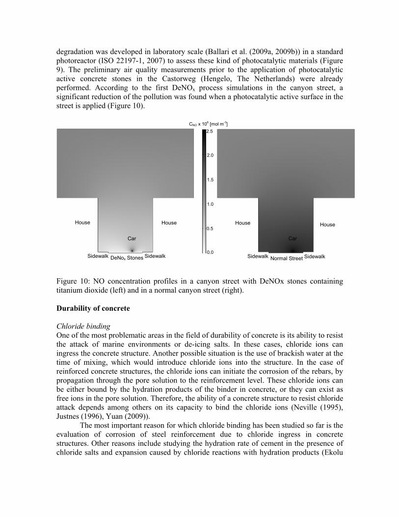
degradation was developed in laboratory scale (Ballari et al. (2009a, 2009b)) in a standard photoreactor (ISO 22197-1, 2007) to assess these kind of photocatalytic materials (Figure 9). The preliminary air quality measurements prior to the application of photocatalytic active concrete stones in the Castorweg (Hengelo, The Netherlands) were already performed. According to the first DeNOx process simulations in the canyon street, a significant reduction of the pollution was found when a photocatalytic active surface in the street is applied (Figure 10).
House House
Car
DeNox Stones Sidewalk Sidewalk
House House
Sidewalk Sidewalk Normal Street
Car
2.5
2.0
1.5
1.0
0.5
CNO x 106 [mol m-3]
0.0
Figure 10: NO concentration profiles in a canyon street with DeNOx stones containing titanium dioxide (left) and in a normal canyon street (right). Durability of concrete Chloride binding One of the most problematic areas in the field of durability of concrete is its ability to resist the attack of marine environments or de-icing salts. In these cases, chloride ions can ingress the concrete structure. Another possible situation is the use of brackish water at the time of mixing, which would introduce chloride ions into the structure. In the case of reinforced concrete structures, the chloride ions can initiate the corrosion of the rebars, by propagation through the pore solution to the reinforcement level. These chloride ions can be either bound by the hydration products of the binder in concrete, or they can exist as free ions in the pore solution. Therefore, the ability of a concrete structure to resist chloride attack depends among others on its capacity to bind the chloride ions (Neville (1995), Justnes (1996), Yuan (2009)).
The most important reason for which chloride binding has been studied so far is the evaluation of corrosion of steel reinforcement due to chloride ingress in concrete structures. Other reasons include studying the hydration rate of cement in the presence of chloride salts and expansion caused by chloride reactions with hydration products (Ekolu

et al. (2006)). Another purpose for this kind of investigation is to accumulate data in order to be able to predict the chloride ingress into concrete, using different numerical methods. A promising new approach to these problems is the analysis of chemical reactions and physical interactions between the hydration products of binders and foreign ions. Knowledge of these phenomena would enable the design of new concrete mixes that are able to better resist chloride attack.
There are several factors that influence chloride binding. Perhaps the most important one is the way chloride ions were added to the concrete mix. Using this criteria, chloride ions can be divided in two categories: internal chloride (when the chloride solution is intermixed with the cement powder), or external chloride (when the chloride ions intrude in already hardened cement paste or concrete), as researched by Arya (1990), Larsen (1998), Zibara (2001) and Tang (1993). The more frequent case is the one of external chlorides, since the amount of internal chlorides is restricted and their use is currently discouraged.
There is an important distinction to be made between the different sources of chloride ions. The most studied two salts are calcium chloride and sodium chloride, which give different results due to their different binding mechanisms. Another interesting source of chloride ions that has been investigated is seawater (Arya (1990)). This approach is of a definite importance, bringing experimental studies closer to the practical engineering problems. The typical concentration of NaCl in seawater is fairly constant (e.g. the Atlantic Ocean: 3.3-3.7% wt., the North Sea: 3.4-3.5% wt., the Persian Gulf: 3.6-3.9% wt.). These concentrations (between 3.4 and 3.9% wt.) correspond to a range of 0.6-0.7 mol NaCl/ L seawater. Another reason for investigating NaCl as a source of chloride ions is its use in the rapid chloride migration (RCM) test. This widely-used accelerated test for determining chloride ingress into concrete uses a value for the concentration of the external solution of 2 mol NaCl/ L immersion solution (Tang (1993)).
The amount of bound chlorides has been related to the cement hydration products or to the cement mineral composition by many researchers. Justnes (1996) concluded, after an extensive literature review, that chloride binding into cementitious materials is dominated by the content of calcium aluminates and calcium aluminoferrites (by forming Friedel’s salt). However, Neville (1995) argued that the hypothesis according to which the content of aluminates in cement is proportional to its chloride binding ability is only valid in the case of intermixed chlorides. His study states that the formation of Friedel’s salt or chloroferrite from the aluminates takes place rapidly during hydration, while in the case of external chlorides, a smaller amount of chloroaluminates is formed, and that they may become dissociated under certain circumstances, releasing chloride ions so as to replenish those removed from the pore water by transport to the surface of the steel reinforcement. In regard to chloride binding, two main chloride binding mechanisms – through physical adsorption and through chemical reactions- are considered, along with quantifying the amount of chloride in the pore solution. Out of the considered hydration products in OPC hardened paste, two hydrated phases are known to be able to bind chloride ions- the calcium hydrosilicate (CSH) phase and the monosulphate (AFm) phase (Tang (1996), Larsen (1998), Zibara (2001)).
Chloride ions ingressed in the hardened cement paste can be divided into two large groups: free chloride ions, existing in the pore solution, and bound chloride ions, attached to various hydration products. Their sum constitutes the total chloride content of the

hardened cement paste. New insights into the quantities of hydration products of OPC (Brouwers 2004, 2005) enables the evaluation of both free and bound chlorides, as well as total chlorides, in relation to the composition of cement. The quantities of hydration products can be calculated for saturated state hydration and for samples that have been dried to 11% rh after a certain time of hydration (the usual case in chloride binding experimental work). Total porosity of the hardened cement paste can be estimated, thus enabling the evaluation of the maximum content of free chlorides in the pore solution. The prediction of total chloride binding is facilitated by knowledge of the amounts of hydrated phases formed (CSH, AFm) that can physically or chemically bind chlorides. Rapid migration tests As mentioned before, another approach to evaluating the durability of concrete exposed to chloride attack is the Rapid Chloride Migration test. The chloride penetration resistance of concrete is an important durability parameter. Usually it is expressed as the chloride ion diffusion coefficient – D [m2/s]. To determine the transport properties of the chloride ion in concrete, several laboratory test method have been developed. The most accurate of them are based on the natural chloride diffusion process, thus the period of testing is usually very long (even up to several months). Furthermore, after the long time of exposure to the chloride solution, it is required to obtain the chloride concentration profile in the concrete – which is very laborious and costly. In view of these disadvantages an intensive research was conducted to develop a new (and more practical) test method and resulted in a few new techniques. Among these, a very innovative one – called the Rapid Chloride Migration (RCM) test - was developed and finally published by Tang (1996). To perform the RCM test, a Ca(OH)2-saturated concrete disc is clamped in a rubber sleeve and then placed in the apparatus as shown in Figure 11. The sample is exposed to a chloride solution on one side, while a solution on the other side is chloride-free (NaOH solution). Then an electrical potential is applied between 2 electrodes immersed in the electrolytes and the chloride ions are forced to penetrate the concrete. Depending on the initial value of the current, the magnitude of the applied potential is selected (between 15 and 60 volts) as well as the testing time (from 8 up to 96 hours).
Figure 11 Schematic and actual Rapid Chloride Migration test set-up

Finally the sample is split and sprayed with a silver nitrate (AgNO3) solution. The chloride ions present in the concrete will react with the silver nitrate creating a whitish precipitate (AgCl). Then the penetration depth of the chloride ions can be measured, and based on this value the chloride ion migration coefficient (DRCM) can be calculated. The simplicity, the final output expressed as the chloride ion transport property in concrete, and finally the rapidity of the test are the biggest advantages of the RCM test method. However, a discussion about the scientific background of the method rose in the past few years and there are still many doubts and questions about it. One of the biggest controversy concerns the very sharp chloride concentration profile (Figure 12) which is assumed to calculate the output parameter of the test – chloride ion migration coefficient. It was reported by a few researchers (Castellote et al. (2002), Stanish (2002), Yuan (2007)) that the real chloride concentration profile is different (Figure 13).
Figure 12 Sharp chloride concentration Figure 13 Chloride concentration profile profile assumed in the RCM procedure observed in concrete after the RCM test The wrong assumption of the chloride concentration profile shape leads to the incorrectness of the solution of the mathematical model describing the migration process. A try of explanation of the real chloride concentration profile, presented by Stanish (2002), considers the influence of the pore structure on the transport of ions. However, the influence of the chloride binding in concrete on the chloride concentration profile obtained after the RCM test still has not been analyzed. The theoretical model of the RCM test assumes no chloride binding in concrete but the differences between the chloride concentration profiles could be well explained if the binding takes place in a significant scale. If it is proved that the binding process takes place and the effect is properly analyzed, it should be possible to improve the test method. Gypsum (plasterboard) technology Gypsum plasterboard is used widely as fire proof material because of its good fire resistance, aesthetics, and low price. Just take Europe as an example, there are 160 quarries for gypsum in Europe and the number of employees is over 85.000 (Euro gypsum, 2008). However, during fire gypsum takes place dehydration reaction which can cause the failure of even the whole structure the gypsum plasterboard protects. One of the most difficult challenges to increase the fire resistance properties of gypsum plasterboard is to reduce the

shrinkage and cracks during fire. This research first addresses on the hydration of gypsum since it decides the microstructure development and then final properties of the gypsum. The void fraction of gypsum is studied experimentally because it influences strongly both the mechanical and thermal properties of the gypsum plasterboard. As one important thermal parameter of the gypsum plasterboard, thermal conductivity is studied with modelling method up to this stage. Water influence on void fraction Void fraction or porosity plays a very important role since it strongly influences not only the mechanical properties but also the thermal properties of the final gypsum plasterboard. The void fraction is composed of two parts with the first part caused by the volume contraction because of the conversion of hemihydrate to dihydrate via the solution phase and the second part caused by the evacuation of excess water after hydration reads (Brouwers, 2008).
wvvvvwmw
vvmww
vvwvv
wh
wn
whwh
wnwsp +
−=
+−
++
−=+= 000
ww)1m(
ϕϕϕ
(3)
Where φp and is the total volume fraction, φs the volume fraction due to structure shrinkage during hydration, and φw volume fraction of evacuation of excess water, vh/vw the specific volume ratio of hemihydrate/free water (0.36 for α- and 0.38 for β-hemihydrate), vn/vw the specific volume ratio of crystal water/free water (0.81 for α- and 0.71 for β-hemihydrate), w the water/hemihydrate ratio, and w0 the water requirement for the hydration reaction (0.186 for both α- and β-hemihydrate). Substituting the values of α-hemihydrate into equation (4) for full hydration an expression of the void fraction is obtained which is the same as Schiller (1958), who proposed this equation also assuming the volume keeps constant during hydration. An expression is obtained to describe the void fraction of gypsum generated with β-hemihydrate by substituting the values of β-hemihydrate reads.
0.38w13.0
+−
=mw
pϕ (4)
The influence of water on void fraction is studied by experiments and the proposed model is verified by experimental results shown in Figure 14 using β-hemihydrate in full hydration case. Results clearly show the void fraction increases with the increase of water. The perfect agreement between the model value from equation (4) and the experimental data shows clearly the validity of the proposed model.
Figure 14: The influence of water on void fraction of gypsum.

Thermal conductivity The thermal conductivity is one very important thermal parameters of gypsum plasterboard because it plays an important role in fire behaviour. The thermal conductivity becomes more complicated for porous media, which consists of different phases. Kaviany (1995) points out that the heat conduction through fully saturated matrix depends on the structure of the matrix and the thermal conductivity of each phase. One of the most difficult aspects of the analysis of heat conduction through a porous medium is the structural modelling. The thermal conductivity of the solid phase is generally larger than that of the fluid; the manner in which the solid is interconnected influences the conduction. Plasterboard consists of a solid phase and water/air mix in the voids. The thermal conductivity of the voids depends strongly on the amount of moisture (absorbed water) in the voids, since the thermal conductivity of water is 23 times the thermal conductivity of air.
The thermal conductivity of gypsum plasterboard up to a temperature of 105°C can be described best by a three-phase system as first introduced by Somerton et al. (1973). This method requires information about the thermal conductivities which are provided by two-phase systems and the saturation of the voids. The two two-phase systems govern the cases with no saturation and full saturation of the voids. For the two-phase system the Zehner and Schlünder equation with a shape-factor of 5 yields good results. Furthermore, a moisture content of 2.8 % on plasterboard mass is needed to explain the thermal conductivity of the board, which is in line with the values reported in literature (Thomas (2002), Ang and Wang (2004)), and here it appears to depend only on the gypsum content of the solid phase.
Using this moisture content of 2.8%, and the equations of Zehner and Schlünder (1970) with shape factor of 5 and Somerton et al. (1973), measured values for the thermal conductivity of several plasterboards from literature up to 105°C can be predicted excellently. For more elevated temperatures, the two-phase equations (air/solid) also proves to be useful, when one takes account of the appropriate changes in the type of solid (dehydration, decarbonation) and volume (void fraction). Figure 15 shows the results of simulation of thermal conductivity at elevated temperatures.
Figure 15: Simulated thermal conductivity according to the proposed model (thin line) and experimental thermal conductivity (Mehaffey, 1994).
Temperature (°C)
Conductivity (W/(K m))
0 200 400 600 800 10000
0.1
0.2
0.3
0.4
0.5

Conclusions In this paper, examples are given of the modeling and the technical applications of the binders cement, lime and hemi-hydrate, and the resulting products, such as concrete. By the consequent and systematic use of mineral oxide engineering and particle size engineering, these products outperform in regard to technical properties, sustainability and costs.
The particle size engineering approach is based on the packing and internal specific surface area of all solids in a mix. Up to now, already 27 binders (cements, lime, calcium sulphates), 45 fillers (natural stone waste, fly ashes, granulated slags, TiO2 powders etc), 15 sands and 13 gravels (primary, recycled) have been characterized in regard to their PSD (from 10 nm to 32 mm) and specific surface area, and this number is steadily growing. They can all be combined in the newly developed mix design software tool. This mix design method renders the common binders cement, lime and hemi-hydrate into high-tech materials.
Based on mineral oxide engineering, the reactivity of the binders and their hydration can be simulated, and the effect of additions (e.g. by-products) evaluated. Furthermore, the 3-D simulation of the prevailing cement packing and subsequent chemical reactions has proven to be a useful design tool.
Some of the technical properties that have to deal with the durability of materials and/or a structure are more difficult to assess (than for instance the 28 days compressive strength) and to fit in a performance-based product design. For concrete, to assess the susceptibility to chloride ingress and rebar corrosion, accelerated tests are developed (such as Rapid Chloride Migration test, RCM). In order to understand and optimize the chloride binding capacity, again mineral oxide engineering can be deployed.
Summarizing, the combined particle size engineering and mineral oxide engineering presented here, enable a cost effective and sustainable development of civil and residential structures. Acknowledgements The author wishes to express his gratitude towards the following sponsors of his research (group): - The Cornelis Lely Foundation; - The European Commission (FP6 Integrated Project I-Stone, Proposal No. 515762-2 and FP6 Integrated Project I-SSB, Proposal No. 026661-2); - SenterNovem (EOS Lowex, No. LT02003). - The user/sponsor group “Cement-Immobilisates-Concrete”, consisting of (in chronological order of joining): Bouwdienst Rijkswaterstaat, Rokramix, Betoncentrale Twenthe, Graniet-Import Benelux, Kijlstra Beton, Struyk Verwo Groep, Hülskens, Insulinde, Dusseldorp Groep, Eerland Recycling, Enci, Provincie Overijssel, Rijkswaterstaat Directie Zeeland, A&G Maasvlakte, BTE, Alvon Bouwsystemen and V.d Bosch Beton.

Furthermore, the contributions of the following researchers are acknowledged, Dipl.-Ing. M. Hunger, Dipl.-Ing. G. Hüsken, A.G. Entrop M.Sc., Ir. A.C.J. de Korte, Q. Yu M.Sc., Dr. M.M. Ballari, P. Spiesz M.Sc. and Dipl. Eng. M.V.A. Marinescu, as well as the technical support from Ing. G.H. Snellink and Mr. J. Dogger. Literature Ang, C. N., and Y.C. Wang (2004), The effect of water movement on specific heat of gypsum plasterboard in heat transfer analysis under natural fire exposure. Construction and Building Materials, vol. 18, p. 505-515. Arya, C., Buenfeld, N.R. and J.B. Newman (1990): Factors Influencing Chloride-binding in Concrete, Cem. Concr. Res., vol. 20, p. 291-300. Bornemann, R (2005), Untersuchung zur Modellierung des Frisch- und Festbetonverhaltens erdfeuchter Betone, PhD Thesis, University of Kassel (189 p.), 26 January 2005, Kassel, Germany (in German). Ballari, M.M., Hunger, M., Hüsken, G. and H.J.H. Brouwers (2009a), Heterogeneous Photocatalysis Applied to Concrete Pavement for Air Remediation, 3rd International Symposium on Nanotechnology in Construction, Prague, Czech Republic. Ballari, M.M., Hunger, M., Hüsken, G. and H.J.H. Brouwers (2009b), Photocatalytic Concrete Stones with TiO2 for Atmospheric NOx Removal, 17th Ibausil (Internationale Baustofftagung/International Conference on Building Materials), Weimar, Germany. Brouwers, H.J.H. and R.J. van Eijk (2003), Alkali concentrations of pore solution in hydrating OPC, Cement and Concrete Research, vol. 33, p. 191-196. Brouwers, H.J.H. (2004), The work of Powers and Brownyard revisited: Part 1, Cement and Concrete Research, vol. 34, p. 1697-1716. Brouwers, H.J.H. (2005), The work of Powers and Brownyard revisited: Part 2, Cement and Concrete Research, vol. 35, p. 1922-1936. Brouwers, H.J.H. and H.J. Radix (2005), Self-compacting concrete: theoretical and experimental study, Cement and Concrete Research, vol. 35, p. 2116-2136. Brouwers, H.J.H. (2006), The packing fraction of random geometric packings, Physical Review E 74, 031309-1-031309-14, Erratum, ibid, 069901(E) (2006).. Brouwers, H.J.H. (2009), A hydration model for Portland cement using the work of Powers and Brownyard (in press). Castellote M., Andrade, C. and C. Alonso (2002), Accelerated simultaneous determination of the chloride depasivation threshold and of the non-stationary diffusion coefficient values, Corrosion Science, vol. 44, 2409-2424. Chen, W. and H.J.H. Brouwers (2007a), Reaction models for alkali-activated slag, Journal of Materials Science, vol. 42, 428-443. Chen, W. and H.J.H. Brouwers (2007b), Reaction models for slag blended cement, Journal of Materials Science, vol. 42, 444-464. Chen, W. (2007), Hydration of slag cement; theory, modeling and application, PhD Thesis, University of Twente (223 p.), 25 January 2007, Enschede, The Netherlands. De Larrard, F. and T. Sedran (1994), Optimization of ultra-high-performance concrete by the use of a packing model, Cement and Concrete Research, vol. 24, p. 997-1009.

Ekolu, S.O., Thomas, M.D.A. and R.D. Hooton (2006), Pessimum effect of externally applied chlorides on expansion due to delayed ettringite formation: Proposed mechanism, Cem. Concr. Res., vol. 36, p. 688-696. EU - The Council of the European Union (1999), Council Directive 1999/30/EC - Relating to Limit Values for Sulphur Dioxide, Nitrogen Dioxide and Oxides of Nitrogen, Particulate Matter and Lead in Ambient Air. Eurogypsum (2008), http://www.eurogypsum.org/industry_01.html Féret, R. (1892), Sur la compacité des mortiers hydrauliques, Ann. Ponts Chaussée, mémoires et documents, Série 7, no. IV, p. 5-164 (in French). Fujishima, A., Hashimoto, K. and Watanabe, T., (1999), TiO2 Photocatalysis Fundaments and Applications, Chiyoda-ku, Tokyo. Fuller, W.B. and S.E. Thompson (1907), The laws of proportioning concrete, Trans. Am. Soc. Civ. Eng., vol. 33, p. 222-298. Hunger, M. and H.J.H. Brouwers (2008), Natural stone waste powders applied to SCC mix design, Restoration of Buildings and Monuments (Bauinstandsetzen und Baudenkmalpflege), vol. 14, p. 131-140. Hunger, M. (2009), Development of eco Self Compacting Concrete, Ph.D. Thesis, in progress. Hüsken, G. and H.J.H. Brouwers (2008). A new mix design concept for earth-moist concrete: A theoretical and experimental study, Cement and Concrete Research, vol. 38, p. 1246–1259. ISO 22197-1 (2007), Fine Ceramics (Advanced Ceramics, Advanced Technical Ceramics) ÷ Test Method for Air Purification Performance of Semiconducting Photocatalytic Materials ÷ Part 1: Removal of Nitric Oxide, First edition. Justnes, H. (1996), A Review of Chloride Binding in Cementitious Systems, Cement and concrete, Trondheim, Norway. Juvas, K.J. (1996). Very dry Precasting concretes. In: Production Methods and Workability of Concrete, Proceedings of the International RILEM Conference, E & FN Spon, London, p. 125-140. Kaviany, M. (1995). Principles of Heat Transfer in Porous Media (Second ed.). Berlin, Germany: Springer. Larsen, C.K. (1998), “Chloride binding in concrete-Effect of surrounding environment and concrete composition”, Ph.D. Thesis, The Norwegian University of Science and Technology, Norway. Mehaffey, J. R., Cuerrier, P., and G. Carisse (1994). A model for predicting heat transfer through gypsum-board/wood-stud walls exposed to fire. Fire and Materials, vol. 18, p. 297-305. Mullin, J.W. (1972), Crystalisation. Second ed., London: Butterworth and Co (Publishers) Ltd. Nagataki, S. (1998), Present state of superplasticizers in Japan, International Symposium on Mineral and Chemical Admixtures in Concrete, April 1998, Toronto, Canada. Neville, A. (1995): Chloride Attack of Reinforced Concrete: an overview, Materials and Structures, vol. 28, p. 63-70. Plum, N.M. (1950), The predetermination of water requirement and optimum grading of concrete under various conditions, Building Research Studies No. 3/Statens

Byggeforskningsinstitut Studie Nr. 3, The Danish National Institute of Building Research, Copenhagen. Powers, T.C. and T.L. Brownyard (1948), Studies of the physical properties of hardened Portland cement paste, Bull. 22, Res. Lab. of Portland Cement Association, Skokie, IL, U.S., reprinted from J. Am. Concrete Inst. (Proc.), vol. 43 (1947), p. 101-132, p. 249-336, p. 469-505, p. 549-602, p. 669-712, p. 845-880, p. 933-992. Reinhardt, H.W (1998), Beton als constructiemateriaal, Delftse Universitaire Pers, Delft, The Netherlands (in Dutch). Richardson, I. G. and G.W. Groves (1992), Microstructure and microanalysis of hardened cement pastes involving ground granulated blast-furnace slag, Journal of Materials Science, vol. 27, p. 6204-6212. Schiller, K.K. (1958). Porosity and strength of brittle solids (with particular reference to gypsum). In Mechanical properties of non-brittle materials (pp. 35-49), London, UK: Butterworths Scientific Publications. Somerton, W. H., Chu, S. L. and J.A. Keese (1973), Thermal behavior of unconsolidated oil sands, Soc. Pet. Eng. AIME, Pap, 4506(48),Verma 1999. Stanish, K.D. (2002), The migration of chloride ions in concrete, PhD Thesis, University of Toronto. Tang L. (1996), Chloride transport in concrete – measurement and prediction, PhD Thesis, Chalmers University of Technology, Gotenburg, Sweden. Tang, L. and L.O. Nilsson (1993), Chloride Binding Capacity and Binding Isotherms of OPC Pastes and Mortars, Cem. Concr. Res., vol. 23, p. 247-253. Thomas, G. (2002), Thermal properties of gypsum plasterboard at high temperatures, Fire and Materials, vol. 26, p. 37-45. Van Eijk, R.J. (2001), Hydration of cement mixtures containing contaminants, Design and application of the solidified product, PhD Thesis, University of Twente (200 p.), 22 June 2001, Enschede, The Netherlands. Wirsching, F. Calcium Sulfate. 2005 Wiley-VCH Verlag GmbH & Co. KGaA, Weinheim, Germany. Yuan, Q. (2009), The relationship between chloride diffusion and migration coefficients in concrete, PhD thesis, University of Ghent, Belgium. Zehner, P. and E.U. Schlunder (1970), Thermal conductivity of granular materials at moderate temperatures. Chemie Ingenieur Technik, vol. 42, p. 933–941. Zibara, H. (2001), Binding of external chloride by cement pastes, PhD thesis, Department of Building Materials, University of Toronto, Canada. Author Prof. dr. ir. H.J.H. (Jos) Brouwers Eindhoven University of Technology Department of Architecture, Building and Planning P.O. Box 513 NL ─ 5600 MB Eindhoven