topics: power in ac circuits questions: lab exercise ... · pdf file... lissajous figures for...
TRANSCRIPT

ELTR 115 (AC 2), section 2
Recommended schedule
Day 1Topics: Power in AC circuitsQuestions: 1 through 20Lab Exercise: Lissajous figures for phase shift measurement (question 71)
Day 2Topics: Power factor correctionQuestions: 21 through 40Lab Exercise: Power factor correction for AC motor (question 72)
Day 3Topics: Alternator construction and introduction to polyphase ACQuestions: 41 through 55Lab Exercise: Power factor correction for AC motor (question 72, continued)
Day 4Topics: AC motor construction and polyphase AC circuitsQuestions: 56 through 70Lab Exercise: work on project
Day 5Exam 2: includes Lissajous figure phase shift measurement performance assessment
Practice and challenge problemsQuestions: 74 through the end of the worksheet
Impending deadlinesProject due at end of ELTR115, Section 3Question 73: Sample project grading criteria
1

ELTR 115 (AC 2), section 2
Skill standards addressed by this course section
EIA Raising the Standard; Electronics Technician Skills for Today and Tomorrow, June 1994
C Technical Skills – AC circuitsC.01 Demonstrate an understanding of sources of electricity in AC circuits.C.04 Demonstrate an understanding of basic motor/generator theory and operation.C.05 Demonstrate an understanding of measurement of power in AC circuits.C.30 Understand principles and operations of AC polyphase circuits.
B Basic and Practical Skills – Communicating on the JobB.01 Use effective written and other communication skills. Met by group discussion and completion of labwork.B.03 Employ appropriate skills for gathering and retaining information. Met by research and preparation
prior to group discussion.B.04 Interpret written, graphic, and oral instructions. Met by completion of labwork.B.06 Use language appropriate to the situation. Met by group discussion and in explaining completed labwork.B.07 Participate in meetings in a positive and constructive manner. Met by group discussion.B.08 Use job-related terminology. Met by group discussion and in explaining completed labwork.B.10 Document work projects, procedures, tests, and equipment failures. Met by project construction and/or
troubleshooting assessments.C Basic and Practical Skills – Solving Problems and Critical Thinking
C.01 Identify the problem. Met by research and preparation prior to group discussion.C.03 Identify available solutions and their impact including evaluating credibility of information, and locating
information. Met by research and preparation prior to group discussion.C.07 Organize personal workloads. Met by daily labwork, preparatory research, and project management.C.08 Participate in brainstorming sessions to generate new ideas and solve problems. Met by group discussion.
D Basic and Practical Skills – ReadingD.01 Read and apply various sources of technical information (e.g. manufacturer literature, codes, and
regulations). Met by research and preparation prior to group discussion.E Basic and Practical Skills – Proficiency in Mathematics
E.01 Determine if a solution is reasonable.E.02 Demonstrate ability to use a simple electronic calculator.E.05 Solve problems and [sic] make applications involving integers, fractions, decimals, percentages, and
ratios using order of operations.E.06 Translate written and/or verbal statements into mathematical expressions.E.09 Read scale on measurement device(s) and make interpolations where appropriate. Met by oscilloscope
usage.E.12 Interpret and use tables, charts, maps, and/or graphs.E.13 Identify patterns, note trends, and/or draw conclusions from tables, charts, maps, and/or graphs.E.15 Simplify and solve algebraic expressions and formulas.E.16 Select and use formulas appropriately.E.17 Understand and use scientific notation.E.26 Apply Pythagorean theorem.E.27 Identify basic functions of sine, cosine, and tangent.E.28 Compute and solve problems using basic trigonometric functions.
F Additional Skills – ElectromechanicsB.01e Types of motors.
2

ELTR 115 (AC 2), section 2
Common areas of confusion for students
Difficult concept: Power factor.The very idea of such a thing as ”imaginary power” (reactive power) is hard to grasp. Basically, what
we’re talking about here is current in an AC circuit that is not contributing to work being done because it isout of phase with the voltage waveform. Instead of contributing to useful work (energy leaving the circuit),it merely stores and releases energy from reactive components. In a purely reactive circuit, all power inthe circuit is ”imaginary” and does no useful work. In a purely resistive circuit, all power is ”real” and isdissipated from the circuit by the resistance (this is also true of motor circuits operating at 100% efficiency,where energy leaves not in the form of heat but in the form of mechanical work). In all realistic circuits,power is some combination of ”real” and ”imaginary;” true and reactive.
Difficult concept: Measuring phase shift with an oscilloscope.Phase shift is not as easy to measure with an oscilloscope as is amplitude or frequency, and it takes
practice to learn. Some students have a tendency to look for memorizable formulae or step-by-step proceduresfor doing this rather than to figure out how and why it works. As I am fond of telling my students, memorywill fail you! Understand, don’t memorize! Phase shift measurement is not as difficult as it may look. Onceyou figure out the relationship between horizontal divisions on the oscilloscope screen and the period (360o)of the waveforms, figuring phase shift is merely a matter of ratio: x divisions of shift is to the number ofdivisions per cycle as y degrees of shift is to 360o.
Difficult concept: Polyphase electric power.Electrical systems having more than one phase (poly-phase) are tremendously useful and prevalent in
modern industry. The idea of having multiple voltages and currents in a system all out of phase with eachother may seem a little weird and confusing, but it is very necessary to know. Perhaps the best way to graspwhat is going on in these systems is to see a video animation of three-phase power being generated, or athree-phase motor in action. As I teacher, I like to use blinking Christmas lights or the motion of crowds ingrandstands sequentially waving (”The Wave”) as an illustration of the large-scale ”motion” one may createwith out-of-phase sequences.
When it comes to mathematically analyzing what is happening in polyphase systems, phasor diagramsare most useful. Try to apply a phasor diagram to polyphase problems which you know the solution(s) to,and then see how the same types of diagrams may apply to problems you are currently trying to solve.
3

Questions
Question 1
Power is easy to calculate in DC circuits. Take for example this DC light bulb circuit:
110 V
I = 2.4 A
Calculate the power dissipation in this circuit, and describe the transfer of energy from source to load:where does the energy come from and where does it go to?
file 02171
Question 2
A generator is coupled to a bicycle mechanism, so that a person can generate their own electricity:
Generator
Load
The person pedaling this bicycle/generator notices that it becomes more difficult to pedal when thegenerator is connected to a load such as a light bulb, or when it is charging a battery. When the generatoris open-circuited, however, it is very easy to spin. Explain why this is, in terms of work and energy transfer.
file 02172
Question 3
If the power waveform is plotted for a resistive AC circuit, it will look like this:
Time
e
i
ei p
What is the significance of the power value always being positive (above the zero line) and never negative(below the zero line)?
file 02174
4
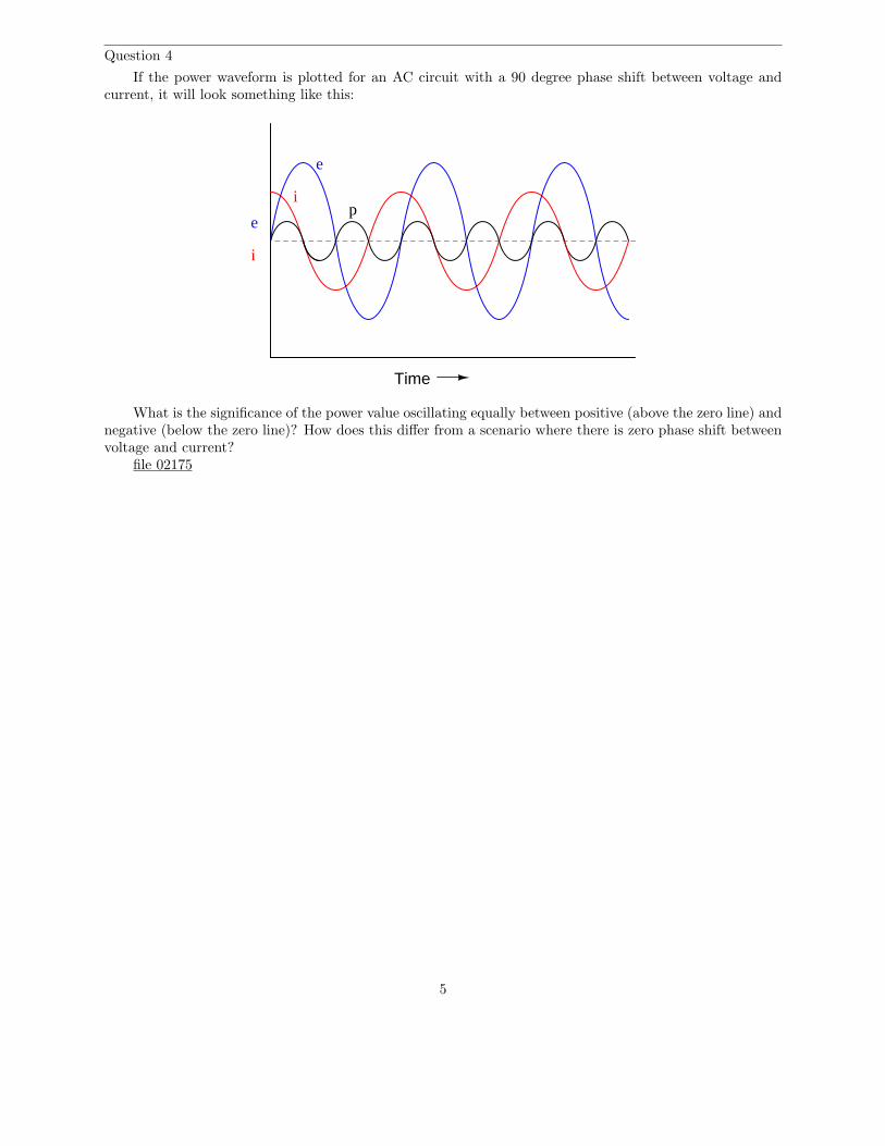
Question 4
If the power waveform is plotted for an AC circuit with a 90 degree phase shift between voltage andcurrent, it will look something like this:
Time
e
i
e
ip
What is the significance of the power value oscillating equally between positive (above the zero line) andnegative (below the zero line)? How does this differ from a scenario where there is zero phase shift betweenvoltage and current?
file 02175
5

Question 5
If this circuit is built and operated, it will be found that the resistor becomes much hotter than theinductor, even though both components drop the exact same amount of voltage and carry the exact sameamount of current:
Alternator
480 VAC60 Hz
9.02 mH
3.4 Ω
OFF
COMA
V A
V A
OFF
COMA
V A
V A
Explain why there is such a remarkable difference in heat output between these two components, giventheir identical voltage drops and currents.
file 02177
Question 6
Calculate the current in this circuit, and also the amount of mechanical power (in units of ”horsepower”)required to turn this alternator (assume 100% efficiency):
Alternator
480 VAC
3.4 Ω
60 Hz
file 00767
6

Question 7
Calculate the current in this circuit, and also the amount of mechanical power (in units of ”horsepower”)required to turn this alternator (assume 100% efficiency):
Alternator
480 VAC60 Hz
9.02 mH
file 00768
7

Question 8
A student is pondering the behavior of a simple series RC circuit:
5 VAC
XC = 4 kΩ
R = 3 kΩ
I = 1 mA
4 V
3 V
It is clear by now that the 4 kΩ capacitive reactance does not directly add to the 3 kΩ resistance tomake 7 kΩ total. Instead, the addition of impedances is vectorial:
√
XC2 + R2 = Ztotal
ZC + ZR = Ztotal
(4kΩ 6 − 90o) + (3kΩ 6 0o) = (5kΩ 6 − 53.13o)
It is also clear to this student that the component voltage drops form a vectorial sum as well, so that 4volts dropped across the capacitor in series with 3 volts dropped across the resistor really does add up to 5volts total source voltage:
VC + VR = Vtotal
(4V 6 − 90o) + (3V 6 0o) = (5V 6 − 53.13o)
What surprises the student, though, is power. In calculating power for each component, the studentarrives at 4 mW for the capacitor (4 volts times 1 milliamp) and 3 mW for the resistor (3 volts times 1milliamp), but only 5 mW for the total circuit power (5 volts times 1 milliamp). In DC circuits, componentpower dissipations always added, no matter how strangely their voltages and currents might be related. Thestudent honestly expected the total power to be 7 mW, but that doesn’t make sense with 5 volts total voltageand 1 mA total current.
Then it occurs to the student that power might add vectorially just like impedances and voltage drops.In fact, this seems to be the only way the numbers make any sense:
PC = 4 mW
PR = 3 mW
Ptotal = 5 mW
However, after plotting this triangle the student is once again beset with doubt. According to the Lawof Energy Conservation, total power in must equal total power out. If the source is inputting 5 mW of power
8

total to this circuit, there should be no possible way that the resistor is dissipating 3 mW and the capacitoris dissipating 4 mW. That would constitute more energy leaving the circuit than what is entering!
What is wrong with this student’s power triangle diagram? How may we make sense of the figuresobtained by multiplying voltage by current for each component, and for the total circuit?
file 02176
Question 9
The three different types of power in AC circuits are as follows:
• S = apparent power, measured in Volt-Amps (VA)• P = true power, measured in Watts (W)• Q = reactive power, measured in Volt-Amps reactive (VAR)
Explain the names of each of these power types. Why are they called ”apparent,” ”true,” and ”reactive”?file 02178
Question 10
Calculate the current in this circuit, and also the amount of mechanical power (in units of ”horsepower”)required to turn this alternator (assume 100% efficiency):
Alternator
480 VAC60 Hz
9.02 mH
3.4 Ω
file 00769
9

Question 11
In this circuit, three common AC loads are modeled as resistances, combined with reactive componentsin two out of the three cases. Calculate the amount of current registered by each ammeter, and also theamount of power dissipated by each of the loads:
Incandescent lampFluorescent lamp Induction motor
A A A
120 VAC, 60 Hz
240 Ω 240 Ω 240 Ω
10 µF 0.25 H
If someone were to read each of the ammeters’ indications and multiply the respective currents by thefigure of 120 volts, would the resulting power figures (P = IE) agree with the actual power dissipations?Explain why or why not, for each load.
file 00770
Question 12
A very important parameter in AC power circuits is power factor. Explain what ”power factor” is, anddefine its numerical range.
file 02173
Question 13
Power calculation in DC circuits is simple. There are three formulae that may be used to calculatepower:
P = IV P = I2R P =V 2
RPower in DC circuits
Calculating power in AC circuits is much more complex, because there are three different types of power:apparent power (S), true power (P ), and reactive power (Q). Write equations for calculating each of thesetypes of power in an AC circuit:
file 02181
10

Question 14
Calculate the power factor of this circuit:
C = 0.1 µF
400 Hz32 V
R = 7.1 kΩ
file 02179
Question 15
Explain the difference between a leading power factor and a lagging power factor.file 00774
Question 16
In this circuit, three common AC loads are represented as resistances, combined with reactivecomponents in two out of the three cases. Calculate the amount of true power (P ), apparent power (S),reactive power (Q), and power factor (PF ) for each of the loads:
Incandescent lampFluorescent lamp Induction motor
A A A
120 VAC, 60 Hz
240 Ω 240 Ω 240 Ω
10 µF 0.25 H
Also, draw power triangle diagrams for each circuit, showing how the true, apparent, and reactive powerstrigonometrically relate.
file 00772
11

Question 17
Calculate the amount of phase shift between voltage and current in an AC circuit with a power factorof 0.97 (lagging), and an apparent power of 3.5 kVA. Also, write the equation solving for phase shift, indegrees.
file 00775
Question 18
A common analogy used to describe the different types of power in AC circuits is a mug of beer thatalso contains foam:
Beer
Foam
Mug
Explain this analogy, relating the quantities of beer and foam to the different types of power in an ACcircuit, and also why this analogy is often employed to describe the ”desirability” of each power type in acircuit.
file 00771
12
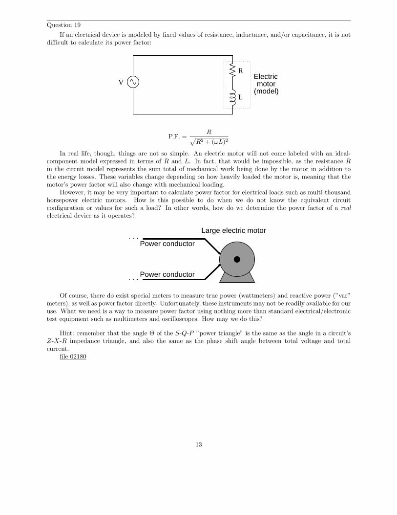
Question 19
If an electrical device is modeled by fixed values of resistance, inductance, and/or capacitance, it is notdifficult to calculate its power factor:
R
L
Electricmotor
(model)V
P.F. =R
√
R2 + (ωL)2
In real life, though, things are not so simple. An electric motor will not come labeled with an ideal-component model expressed in terms of R and L. In fact, that would be impossible, as the resistance Rin the circuit model represents the sum total of mechanical work being done by the motor in addition tothe energy losses. These variables change depending on how heavily loaded the motor is, meaning that themotor’s power factor will also change with mechanical loading.
However, it may be very important to calculate power factor for electrical loads such as multi-thousandhorsepower electric motors. How is this possible to do when we do not know the equivalent circuitconfiguration or values for such a load? In other words, how do we determine the power factor of a realelectrical device as it operates?
. . .
. . .
Large electric motor
Power conductor
Power conductor
Of course, there do exist special meters to measure true power (wattmeters) and reactive power (”var”meters), as well as power factor directly. Unfortunately, these instruments may not be readily available for ouruse. What we need is a way to measure power factor using nothing more than standard electrical/electronictest equipment such as multimeters and oscilloscopes. How may we do this?
Hint: remember that the angle Θ of the S-Q-P ”power triangle” is the same as the angle in a circuit’sZ-X-R impedance triangle, and also the same as the phase shift angle between total voltage and totalcurrent.
file 02180
13

Question 20
Suppose that a single-phase AC electric motor is performing mechanical work at a rate of 45 horsepower.This equates to 33.57 kW of power, given the equivalence of watts to horsepower (1 HP ≈ 746 W).
Calculate the amount of line current necessary to power this motor if the line voltage is 460 volts,assuming 100% motor efficiency and a power factor of 1.
Now re-calculate the necessary line current for this motor if its power factor drops to 0.65. Assume thesame efficiency (100%) and the same amount of mechanical power (45 HP).
What do these calculations indicate about the importance of maintaining a high power factor value inan AC circuit?
file 02182
14

Question 21
A common feature of oscilloscopes is the X − Y mode, where the vertical and horizontal plot directionsare driven by external signals, rather than only the vertical direction being driven by a measured signal andthe horizontal being driven by the oscilloscope’s internal sweep circuitry:
trigger
timebase
s/divDC GND AC
X
GNDDCV/div
vertical
OSCILLOSCOPE
Y
AC
X-Y
trigger
timebase
s/divDC GND AC
X
GNDDCV/div
vertical
OSCILLOSCOPE
Y
AC
AC signalsource
X-Y
X-Y mode
AC signalsource
AC signalsource
AC signalsource
Time-domain mode
The oval pattern shown in the right-hand oscilloscope display of the above illustration is typical for twosinusoidal waveforms of the same frequency, but slightly out of phase with one another. The technical namefor this type of X − Y plot is a Lissajous figure.
What should the Lissajous figure look like for two sinusoidal waveforms that are at exactly the samefrequency, and exactly the same phase (0 degrees phase shift between the two)? What should the Lissajousfigure look like for two sinusoidal waveforms that are exactly 90 degrees out of phase?
A good way to answer each of these questions is to plot the specified waveforms over time on graphpaper, then determine their instantaneous amplitudes at equal time intervals, and then determine wherethat would place the ”dot” on the oscilloscope screen at those points in time, in X − Y mode. To help you,I’ll provide two blank oscilloscope displays for you to draw the Lissajous figures on:
0 degrees phase shift 90 degrees phase shift
15
file 01480
Question 22
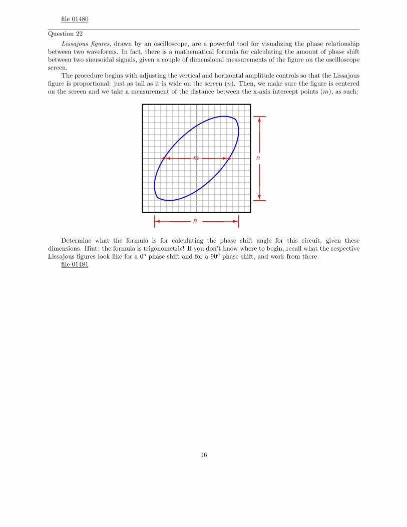
Lissajous figures, drawn by an oscilloscope, are a powerful tool for visualizing the phase relationshipbetween two waveforms. In fact, there is a mathematical formula for calculating the amount of phase shiftbetween two sinusoidal signals, given a couple of dimensional measurements of the figure on the oscilloscopescreen.
The procedure begins with adjusting the vertical and horizontal amplitude controls so that the Lissajousfigure is proportional: just as tall as it is wide on the screen (n). Then, we make sure the figure is centeredon the screen and we take a measurement of the distance between the x-axis intercept points (m), as such:
m n
n
Determine what the formula is for calculating the phase shift angle for this circuit, given thesedimensions. Hint: the formula is trigonometric! If you don’t know where to begin, recall what the respectiveLissajous figures look like for a 0o phase shift and for a 90o phase shift, and work from there.
file 01481
16
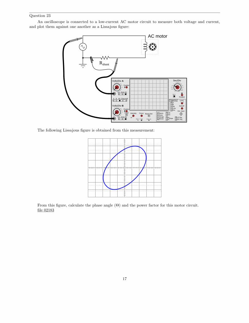
Question 23
An oscilloscope is connected to a low-current AC motor circuit to measure both voltage and current,and plot them against one another as a Lissajous figure:
A B Alt Chop Add
Volts/Div A
Volts/Div B
DC Gnd AC
DC Gnd AC
Invert Intensity Focus
Position
Position
Position
Off
Beam find
LineExt.
AB
ACDC
NormAutoSingle
Slope
Level
Reset
X-Y
Holdoff
LF RejHF Rej
Triggering
Alt
Ext. input
Cal 1 V Gnd Trace rot.
Sec/Div0.5 0.2 0.1
1
10
5
2
20
50 m
20 m
10 m
5 m
2 m
0.5 0.2 0.11
10
5
2
20
50 m
20 m
10 m
5 m
2 m
1 m5 m
25 m
100 m
500 m
2.51
250 µ50 µ
10 µ
2.5 µ
0.5 µ
0.1 µ0.025 µ
off
Rshunt
AC motor
The following Lissajous figure is obtained from this measurement:
From this figure, calculate the phase angle (Θ) and the power factor for this motor circuit.file 02183
17

Question 24
A very high-power AC electric motor needs to have its power factor measured. You and an electricianare asked to perform this measurement using an oscilloscope. The electrician understands what must bedone to measure voltage and current in this dangerous circuit, and you understand how to interpret theoscilloscope’s image to calculate power factor.
It would be impractical to directly measure voltage and current, seeing as how the voltage is 4160 voltsAC and the current is in excess of 200 amps. Fortunately, PT (”potential transformer”) and CT (”currenttransformer”) units are already installed in the motor circuit to facilitate measurements:
CT
PT
Rshunt
A B Alt Chop Add
Volts/Div A
Volts/Div B
DC Gnd AC
DC Gnd AC
Invert Intensity Focus
Position
Position
Position
Off
Beam find
LineExt.
AB
ACDC
NormAutoSingle
Slope
Level
Reset
X-Y
Holdoff
LF RejHF Rej
Triggering
Alt
Ext. input
Cal 1 V Gnd Trace rot.
Sec/Div0.5 0.2 0.1
1
10
5
2
20
50 m
20 m
10 m
5 m
2 m
0.5 0.2 0.11
10
5
2
20
50 m
20 m
10 m
5 m
2 m
1 m5 m
25 m
100 m
500 m
2.51
250 µ50 µ
10 µ
2.5 µ
0.5 µ
0.1 µ0.025 µ
off
power conductor
After the electrician helps you safely connect to the PT and CT units, you obtain a Lissajous figurethat looks like this:
Calculate the power factor of the AC motor from this oscilloscope display.file 02185
18

Question 25
A large electrical load is outfitted with a wattmeter to measure its true power. If the load voltage is 7.2kV and the load current is 24 amps, calculate the load’s apparent power (S). Calculate the power factor andalso the phase angle between voltage and current in the circuit if the wattmeter registers 155 kW at thosesame voltage and current values.
Draw a ”power triangle” for this circuit, graphically showing the relationships between apparent power,true power, and phase angle.
file 02187
Question 26
The power factor of this circuit is as low as it can possibly be, 0:
L = 0.25 H30 V
400 Hz
Calculate the apparent, true, and reactive power for this circuit:
• S =• P =• Q =
Now, suppose a capacitor is added in parallel with the inductor:
L = 0.25 H30 V
400 Hz
C = 0.47 µF
Re-calculate the apparent, true, and reactive power for this circuit with the capacitor connected:
• S =• P =• Q =
file 02186
19
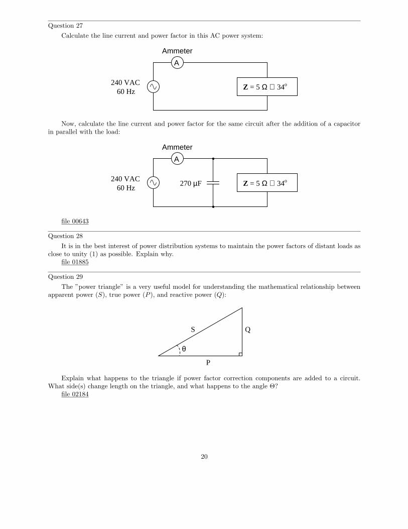
Question 27
Calculate the line current and power factor in this AC power system:
240 VAC60 Hz
A
Ammeter
Z = 5 Ω ∠ 34o
Now, calculate the line current and power factor for the same circuit after the addition of a capacitorin parallel with the load:
240 VAC60 Hz
A
Ammeter
270 µF Z = 5 Ω ∠ 34o
file 00643
Question 28
It is in the best interest of power distribution systems to maintain the power factors of distant loads asclose to unity (1) as possible. Explain why.
file 01885
Question 29
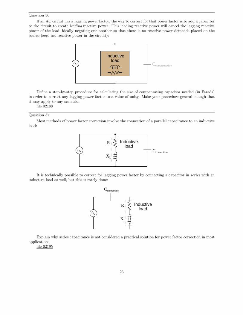
The ”power triangle” is a very useful model for understanding the mathematical relationship betweenapparent power (S), true power (P ), and reactive power (Q):
P
QS
θ
Explain what happens to the triangle if power factor correction components are added to a circuit.What side(s) change length on the triangle, and what happens to the angle Θ?
file 02184
20

Question 30
When a capacitor is to be connected in parallel with an inductive AC load to correct for lagging powerfactor, it is important to be able to calculate the reactive power of the capacitor (QC). Write at least oneequation for calculating the reactive power of a capacitor (in VARs) given the capacitor’s reactance (XC) atthe line frequency.
file 02189
Question 31
An inductive AC load draws 13.4 amps of current at a voltage of 208 volts. The phase shift between linevoltage and line current is measured with an oscilloscope, and determined to be 23o. Calculate the following:
• Apparent power (S) =• True power (P ) =• Reactive power (Q) =• Power factor =
An electrician suggests to you that the lagging power factor may be corrected by connecting a capacitorin parallel with this load. If the capacitor is sized just right, it will exactly offset the reactive power of theinductive load, resulting in zero total reactive power and a power factor of unity (1). Calculate the size ofthe necessary capacitor in Farads, assuming a line frequency of 60 Hz.
file 02168
Question 32
An AC load exhibits a lagging power factor of 0.73 at 230 VAC and 315 amps. If the system frequencyis 60 Hz, calculate the following:
• Apparent power (S) =• True power (P ) =• Reactive power (Q) =• Θ =• Necessary parallel C size to correct power factor to unity =
file 02191
Question 33
An inductive AC load consumes 15.2 MW of true power at a voltage of 115 kV and 149.8 amps. If thesystem frequency is 50 Hz, calculate the following:
• Apparent power (S) =• Reactive power (Q) =• Power factor =• Θ =• Necessary parallel C size to correct power factor to unity =
file 02190
21

Question 34
A dual-trace oscilloscope is used to measure the phase shift between voltage and current for an inductiveAC load:
Calculate the following, given a load voltage of 110 volts, a load current of 3.2 amps, and a frequencyof 60 Hz:
• Apparent power (S) =• True power (P ) =• Reactive power (Q) =• Θ =• Power factor =• Necessary parallel C size to correct power factor to unity =
file 02192
Question 35
Calculate the power factor of this circuit:
Alternator
480 VAC60 Hz
9.02 mH
3.4 Ω
Then, calculate the size of the capacitor necessary to ”correct” the power factor to a value of 1.0, showingthe best location of the capacitor in the circuit.
file 00776
22
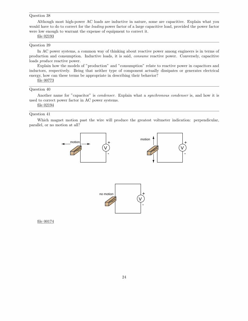
Question 36
If an AC circuit has a lagging power factor, the way to correct for that power factor is to add a capacitorto the circuit to create leading reactive power. This leading reactive power will cancel the lagging reactivepower of the load, ideally negating one another so that there is no reactive power demands placed on thesource (zero net reactive power in the circuit):
Inductiveload
Ccompensation
Define a step-by-step procedure for calculating the size of compensating capacitor needed (in Farads)in order to correct any lagging power factor to a value of unity. Make your procedure general enough thatit may apply to any scenario.
file 02188
Question 37
Most methods of power factor correction involve the connection of a parallel capacitance to an inductiveload:
Ccorrection
Inductive load
R
XL
It is technically possible to correct for lagging power factor by connecting a capacitor in series with aninductive load as well, but this is rarely done:
Ccorrection
Inductive load
R
XL
Explain why series capacitance is not considered a practical solution for power factor correction in mostapplications.
file 02195
23
Question 38
Although most high-power AC loads are inductive in nature, some are capacitive. Explain what youwould have to do to correct for the leading power factor of a large capacitive load, provided the power factorwere low enough to warrant the expense of equipment to correct it.
file 02193
Question 39
In AC power systems, a common way of thinking about reactive power among engineers is in terms ofproduction and consumption. Inductive loads, it is said, consume reactive power. Conversely, capacitiveloads produce reactive power.
Explain how the models of ”production” and ”consumption” relate to reactive power in capacitors andinductors, respectively. Being that neither type of component actually dissipates or generates electricalenergy, how can these terms be appropriate in describing their behavior?
file 00773
Question 40
Another name for ”capacitor” is condenser. Explain what a synchronous condenser is, and how it isused to correct power factor in AC power systems.
file 02194
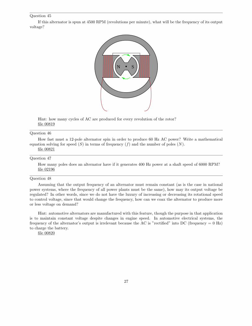
Question 41
Which magnet motion past the wire will produce the greatest voltmeter indication: perpendicular,parallel, or no motion at all?
+V
-
motion +V
-
motion
magnet
magnet
+V
-magnet
no motion
file 00174
24

Question 42
We know that in order to induce a sinusoidal voltage in a wire coil, the magnetic flux linking the turnsof wire in the coil must follow a sinusoidal path over time, phase-shifted 90o from the voltage waveform.This relationship between flux and induced voltage is expressed in Faraday’s equation v = N dφ
dt:
e
φ
Based on this fact, draw the position of the magnetic rotor in this alternator when the voltage is at oneof its peaks:
N
S
???
file 00818
25

Question 43
Describe the nature of the voltage induced in the stationary (”stator”) windings, as the permanentmagnet rotor rotates in this machine:
N S
iron
wire wire
What factors determine the magnitude of this voltage? According to Faraday’s Law, what factors canwe alter to increase the voltage output by this generator?
Is the induced voltage AC or DC? How can you tell?file 00816
Question 44
In order to make the most practical AC generator (or alternator, as it is also known), which design makesmore sense: a stationary permanent magnet with a rotating wire coil, or a rotating permanent magnet witha stationary wire coil? Explain your choice.
file 00817
26
Question 45
If this alternator is spun at 4500 RPM (revolutions per minute), what will be the frequency of its outputvoltage?
N S
Hint: how many cycles of AC are produced for every revolution of the rotor?file 00819
Question 46
How fast must a 12-pole alternator spin in order to produce 60 Hz AC power? Write a mathematicalequation solving for speed (S) in terms of frequency (f) and the number of poles (N).
file 00821
Question 47
How many poles does an alternator have if it generates 400 Hz power at a shaft speed of 6000 RPM?file 02196
Question 48
Assuming that the output frequency of an alternator must remain constant (as is the case in nationalpower systems, where the frequency of all power plants must be the same), how may its output voltage beregulated? In other words, since we do not have the luxury of increasing or decreasing its rotational speedto control voltage, since that would change the frequency, how can we coax the alternator to produce moreor less voltage on demand?
Hint: automotive alternators are manufactured with this feature, though the purpose in that applicationis to maintain constant voltage despite changes in engine speed. In automotive electrical systems, thefrequency of the alternator’s output is irrelevant because the AC is ”rectified” into DC (frequency = 0 Hz)to charge the battery.
file 00820
27

Question 49
Suppose a set of three neon light bulbs were connected to an alternator with three sets of windingslabeled A, B, and C:
A
A
B
B C
C
N S
A
B
C
ABC
The schematic diagram for this alternator/lamp system is as follows:
Alternator
A B CB AC
If the alternator spins fast enough (clockwise, as shown), the AC voltage induced in its windings willbe enough to cause the neon lamps to ”blink” (neon bulbs have very fast reaction times and thus cannotmaintain a glow for very long without current, unlike incandescent lamps which operate on the principle ofa glowing-hot metal filament). Most likely this blinking will be too fast to discern with the naked eye.
However, if we were to videorecord the blinking and play back the recording at a slow speed, we shouldbe able to see the sequence of light flashes. Determine the apparent ”direction” of the lamps’ blinking (fromright-to-left or from left-to-right), and relate that sequence to the voltage peaks of each alternator coil pair.
file 02198
28
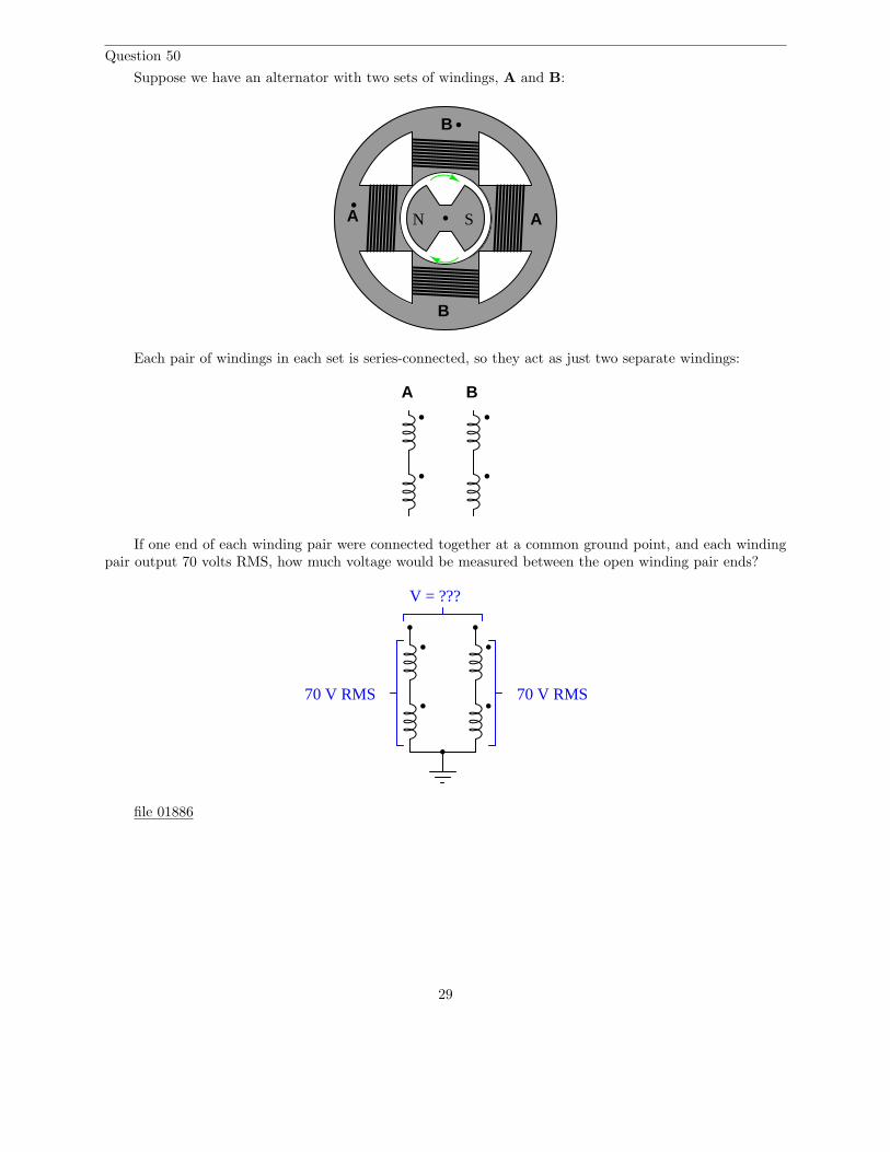
Question 50
Suppose we have an alternator with two sets of windings, A and B:
N SA A
B
B
Each pair of windings in each set is series-connected, so they act as just two separate windings:
A B
If one end of each winding pair were connected together at a common ground point, and each windingpair output 70 volts RMS, how much voltage would be measured between the open winding pair ends?
70 V RMS 70 V RMS
V = ???
file 01886
29
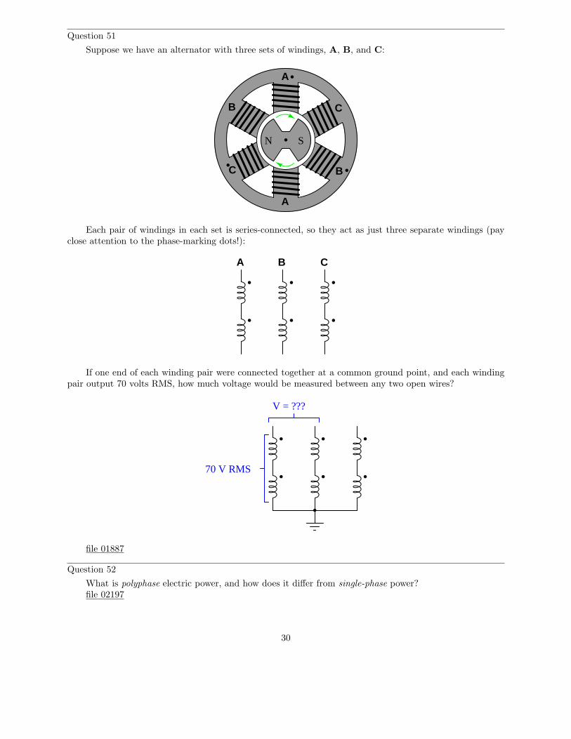
Question 51
Suppose we have an alternator with three sets of windings, A, B, and C:
A
A
B
B C
C
N S
Each pair of windings in each set is series-connected, so they act as just three separate windings (payclose attention to the phase-marking dots!):
A B C
If one end of each winding pair were connected together at a common ground point, and each windingpair output 70 volts RMS, how much voltage would be measured between any two open wires?
70 V RMS
V = ???
file 01887
Question 52
What is polyphase electric power, and how does it differ from single-phase power?file 02197
30
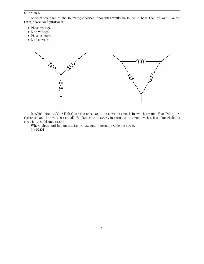
Question 53
Label where each of the following electrical quantities would be found in both the ”Y” and ”Delta”three-phase configurations:
• Phase voltage• Line voltage• Phase current• Line current
In which circuit (Y or Delta) are the phase and line currents equal? In which circuit (Y or Delta) arethe phase and line voltages equal? Explain both answers, in terms that anyone with a basic knowledge ofelectricity could understand.
Where phase and line quantities are unequal, determine which is larger.file 02201
31
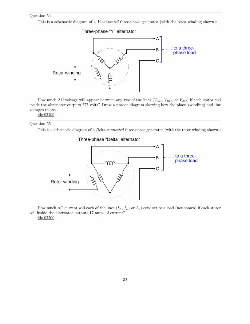
Question 54
This is a schematic diagram of a Y-connected three-phase generator (with the rotor winding shown):
Rotor winding
A
B
C
Three-phase "Y" alternator
. . . to a three-phase load
How much AC voltage will appear between any two of the lines (VAB , VBC , or VAC) if each stator coilinside the alternator outputs 277 volts? Draw a phasor diagram showing how the phase (winding) and linevoltages relate.
file 02199
Question 55
This is a schematic diagram of a Delta-connected three-phase generator (with the rotor winding shown):
Rotor winding
A
B
C
. . . to a three-phase load
Three-phase "Delta" alternator
How much AC current will each of the lines (IA, IB , or IC) conduct to a load (not shown) if each statorcoil inside the alternator outputs 17 amps of current?
file 02200
32
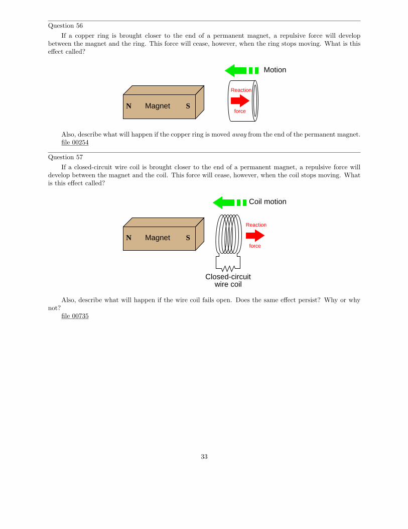
Question 56
If a copper ring is brought closer to the end of a permanent magnet, a repulsive force will developbetween the magnet and the ring. This force will cease, however, when the ring stops moving. What is thiseffect called?
MagnetN S
Motion
Reaction
force
Also, describe what will happen if the copper ring is moved away from the end of the permanent magnet.file 00254
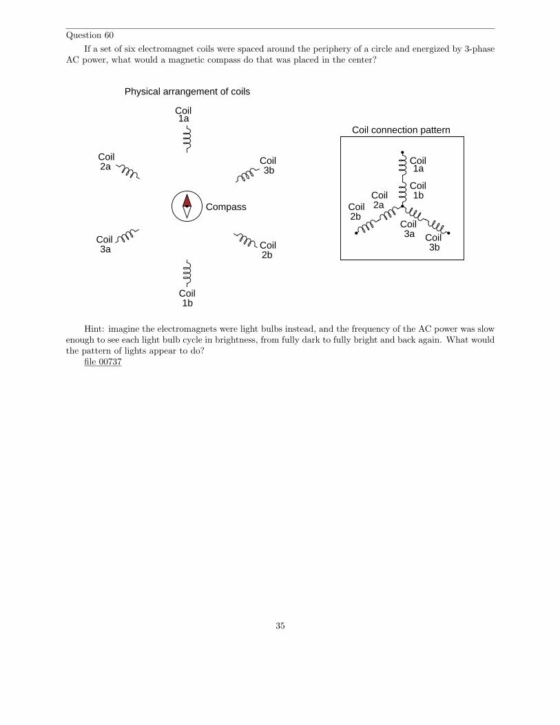
Question 57
If a closed-circuit wire coil is brought closer to the end of a permanent magnet, a repulsive force willdevelop between the magnet and the coil. This force will cease, however, when the coil stops moving. Whatis this effect called?
MagnetN S
Reaction
force
Closed-circuitwire coil
Coil motion
Also, describe what will happen if the wire coil fails open. Does the same effect persist? Why or whynot?
file 00735
33

Question 58
Electromechanical watt-hour meters use an aluminum disk that is spun by an electric motor. To generatea constant ”drag” on the disk necessary to limit its rotational speed, a strong magnet is placed in such away that its lines of magnetic flux pass perpendicularly through the disk’s thickness:
shaftN
SAluminum disk
The disk itself need not be made of a ferromagnetic material in order for the magnet to create a ”drag”force. It simply needs to be a good conductor of electricity.
Explain the phenomenon accounting for the drag effect, and also explain what would happen if the rolesof magnet and disk were reversed: if the magnet were moved in a circle around the periphery of a stationarydisk.
file 00745
Question 59
A technique commonly used in special-effects lighting is to sequence the on/off blinking of a string oflight bulbs, to produce the effect of motion without any moving objects:
1 2 3 1 2 3 1 2 3 1 2 3
1 2 3 1 2 3 1 2 3 1 2 3
1 2 3 1 2 3 1 2 3 1 2 3
1 2 3 1 2 3 1 2 3 1 2 3
phase sequence = 1-2-3
all "1" bulbs lit
all "2" bulbs lit
all "3" bulbs lit
all "1" bulbs lit
Time
bulbs appear to be "moving" from left to right
What would the effect be if this string of lights were arranged in a circle instead of a line? Also, explainwhat would have to change electrically to alter the ”speed” of the blinking lights’ ”motion”.
file 00734
34
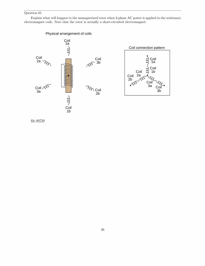
Question 60
If a set of six electromagnet coils were spaced around the periphery of a circle and energized by 3-phaseAC power, what would a magnetic compass do that was placed in the center?
1a
1b
2a
2b3a
3b
Coil
Coil
Coil
CoilCoil
Coil1a
Coil
1bCoil
2aCoil
2bCoil
3aCoil
3bCoil
Coil connection pattern
Physical arrangement of coils
Compass
Hint: imagine the electromagnets were light bulbs instead, and the frequency of the AC power was slowenough to see each light bulb cycle in brightness, from fully dark to fully bright and back again. What wouldthe pattern of lights appear to do?
file 00737
35
Question 61
Explain what will happen to the unmagnetized rotor when 3-phase AC power is applied to the stationaryelectromagnet coils. Note that the rotor is actually a short-circuited electromagnet:
1a
1b
2a
2b3a
3b
Coil
Coil
Coil
CoilCoil
Coil1a
Coil
1bCoil
2aCoil
2bCoil
3aCoil
3bCoil
Coil connection pattern
Physical arrangement of coils
file 00739
36

Question 62
These two electric motor designs are quite similar in appearance, but differ in the specific principle thatmakes the rotor move:
1a
1b
2a
2b3a
3b
Coil
Coil
Coil
CoilCoil
Coil
1a
1b
2a
2b3a
3b
Coil
Coil
Coil
CoilCoil
CoilN
S
Induction motor Synchronous motor
Synchronous AC motors use a permanent magnet rotor, while induction motors use an electromagnetrotor. Explain what practical difference this makes in each motor’s operation, and also explain the meaningof the motors’ names. Why is one called ”synchronous” and the other called ”induction”?
file 00740
Question 63
What would we have to do in order to reverse the rotation of this three-phase induction motor?
motor
On/off switchConnection terminals
From 3-phasepower source
Explain your answer. Describe how the (simple) solution to this problem works.file 00415
37
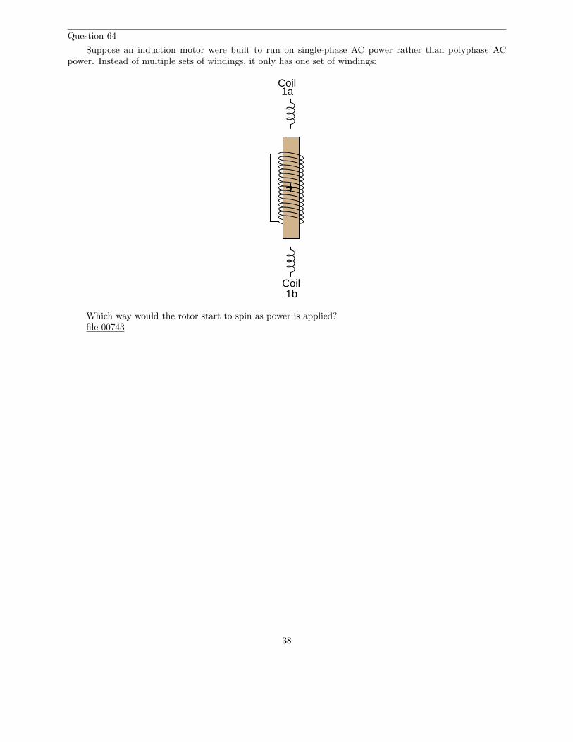
Question 64
Suppose an induction motor were built to run on single-phase AC power rather than polyphase ACpower. Instead of multiple sets of windings, it only has one set of windings:
1a
1b
Coil
Coil
Which way would the rotor start to spin as power is applied?file 00743
38

Question 65
Calculate all voltages, currents, and total power in this balanced Delta-Delta system:
Source Load
230 V50 Ω
Eline =Iline =Ephase(source) =Iphase(source) =Ephase(load) =Iphase(load) =Ptotal =
file 02203
Question 66
Calculate all voltages, currents, and total power in this balanced Y-Y system:
Source Load
13.8 kV
1.5 kΩ
Eline =Iline =Ephase(source) =Iphase(source) =Ephase(load) =Iphase(load) =Ptotal =
file 02202
39
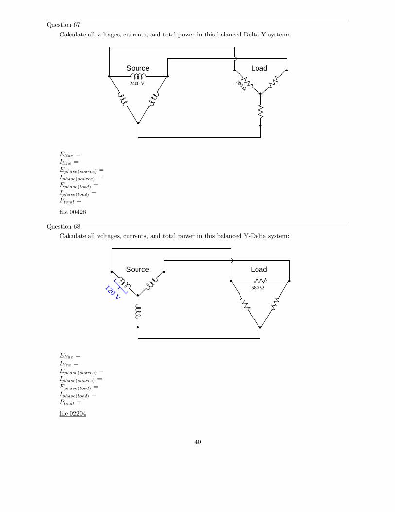
Question 67
Calculate all voltages, currents, and total power in this balanced Delta-Y system:
Source Load
2400 V300 Ω
Eline =Iline =Ephase(source) =Iphase(source) =Ephase(load) =Iphase(load) =Ptotal =
file 00428
Question 68
Calculate all voltages, currents, and total power in this balanced Y-Delta system:
Source Load
120 V580 Ω
Eline =Iline =Ephase(source) =Iphase(source) =Ephase(load) =Iphase(load) =Ptotal =
file 02204
40

Question 69
The line voltage to this three-phase load is 480 volts. How much power (total) is dissipated by the load?How much current is there in each line supplying the load?
Eline = 480 VAC
25 Ω
25 Ω 25 Ω
One more question: write an equation for calculating power in a balanced, three-phase circuit, givenline voltage and line current only.
file 00421
Question 70
A balanced, three-phase power system has a line voltage of 13.8 kV volts and a line current of 150 amps.How much power is being delivered to the load (assuming a power factor of 1)?
Lines
Eline = 13.8 kV
Iline = 150 A
3-phasesource
3-phaseload
A 13.8 kV single-phase system could be designed to provide the same amount of power to a load, butit would require heavier-gauge (more expensive!) conductors. Determine the extra percentage of expense inwire cost (based on the weight of the wires) resulting from the use of single-phase instead of three-phase.
Lines
Eline = 13.8 kV
sourceSingle-phase
loadSingle-phase
file 00414
41
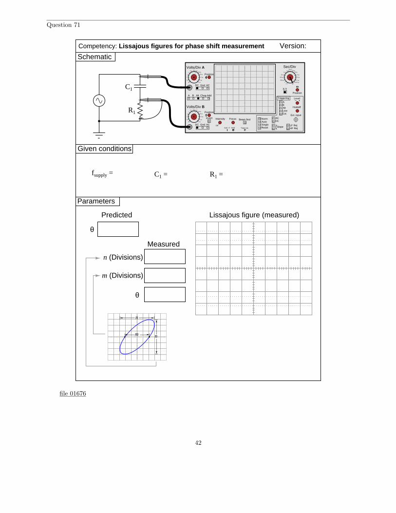
Question 71
Given conditions
Version:
Schematic
Parameters
Predicted
Competency: Lissajous figures for phase shift measurement
fsupply =
θ
Lissajous figure (measured)
Measured
θ
C1 = R1 =
C1
R1
A B Alt Chop Add
Volts/Div A
Volts/Div B
DC Gnd AC
DC Gnd AC
Invert Intensity Focus
Position
Position
Position
Off
Beam find
LineExt.
AB
ACDC
NormAutoSingle
Slope
Level
Reset
X-Y
Holdoff
LF RejHF Rej
Triggering
Alt
Ext. input
Cal 1 V Gnd Trace rot.
Sec/Div0.5 0.2 0.1
1
10
5
2
20
50 m
20 m
10 m
5 m
2 m
0.5 0.2 0.11
10
5
2
20
50 m
20 m
10 m
5 m
2 m
1 m5 m
25 m
100 m
500 m
2.51
250 µ50 µ
10 µ
2.5 µ
0.5 µ
0.1 µ0.025 µ
off
m (Divisions)
n (Divisions)
nm
n
file 01676
42
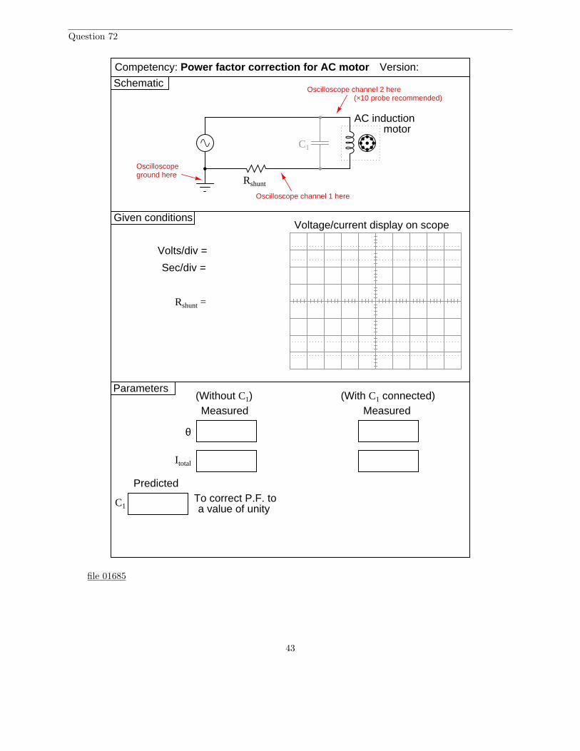
Question 72
Given conditions
Version:
Schematic
Parameters
Competency: Power factor correction for AC motor
C1
Rshunt
Voltage/current display on scope
Measured
θ
Measured(Without C1) (With C1 connected)
Predicted
C1To correct P.F. to a value of unity
Volts/div =
Sec/div =
Rshunt =
Oscilloscopeground here
Oscilloscope channel 1 here
Oscilloscope channel 2 here
AC inductionmotor
Itotal
(×10 probe recommended)
file 01685
43

Question 73
NAME: Project Grading Criteria PROJECT:You will receive the highest score for which all criteria are met.
100 % (Must meet or exceed all criteria listed)A. Impeccable craftsmanship, comparable to that of a professional assemblyB. No spelling or grammatical errors anywhere in any document, upon first submission to instructor
95 % (Must meet or exceed these criteria in addition to all criteria for 90% and below)A. Technical explanation sufficiently detailed to teach from, inclusive of every component (supersedes 75.B)B. Itemized parts list complete with part numbers, manufacturers, and (equivalent) prices for all
components, including recycled components and parts kit components (supersedes 90.A)
90 % (Must meet or exceed these criteria in addition to all criteria for 85% and below)A. Itemized parts list complete with prices of components purchased for the project, plus total priceB. No spelling or grammatical errors anywhere in any document upon final submission
85 % (Must meet or exceed these criteria in addition to all criteria for 80% and below)A. “User’s guide” to project function (in addition to 75.B)B. Troubleshooting log describing all obstacles overcome during development and construction
80 % (Must meet or exceed these criteria in addition to all criteria for 75% and below)A. All controls (switches, knobs, etc.) clearly and neatly labeledB. All documentation created on computer, not hand-written (including the schematic diagram)
75 % (Must meet or exceed these criteria in addition to all criteria for 70% and below)A. Stranded wire used wherever wires are subject to vibration or bendingB. Basic technical explanation of all major circuit sectionsC. Deadline met for working prototype of circuit (Date/Time = / )
70 % (Must meet or exceed these criteria in addition to all criteria for 65%)A. All wire connections sound (solder joints, wire-wrap, terminal strips, and lugs are all connected properly)B. No use of glue where a fastener would be more appropriateC. Deadline met for submission of fully-functional project (Date/Time = / ) –
supersedes 75.C if final project submitted by that (earlier) deadline
65 % (Must meet or exceed these criteria in addition to all criteria for 60%)A. Project fully functionalB. All components securely fastened so nothing is “loose” inside the enclosureC. Schematic diagram of circuit
60 % (Must meet or exceed these criteria in addition to being safe and legal)A. Project minimally functional, with all components located inside an enclosure (if applicable)B. Passes final safety inspection (proper case grounding, line power fusing, power cords strain-relieved)
0 % (If any of the following conditions are true)A. Fails final safety inspection (improper grounding, fusing, and/or power cord strain relieving)B. Intended project function poses a safety hazardC. Project function violates any law, ordinance, or school policy
file 03173
44
Question 74
If a sinusoidal voltage is applied to an impedance with a phase angle of 0o, the resulting voltage andcurrent waveforms will look like this:
Time
e
i
e
i
Given that power is the product of voltage and current (p = ie), plot the waveform for power in thiscircuit.
file 00631
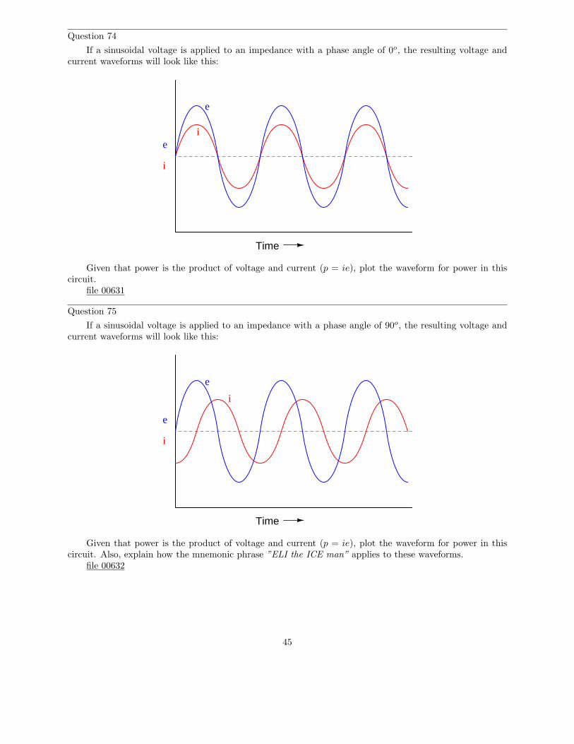
Question 75
If a sinusoidal voltage is applied to an impedance with a phase angle of 90o, the resulting voltage andcurrent waveforms will look like this:
Time
e
i
e
i
Given that power is the product of voltage and current (p = ie), plot the waveform for power in thiscircuit. Also, explain how the mnemonic phrase ”ELI the ICE man” applies to these waveforms.
file 00632
45
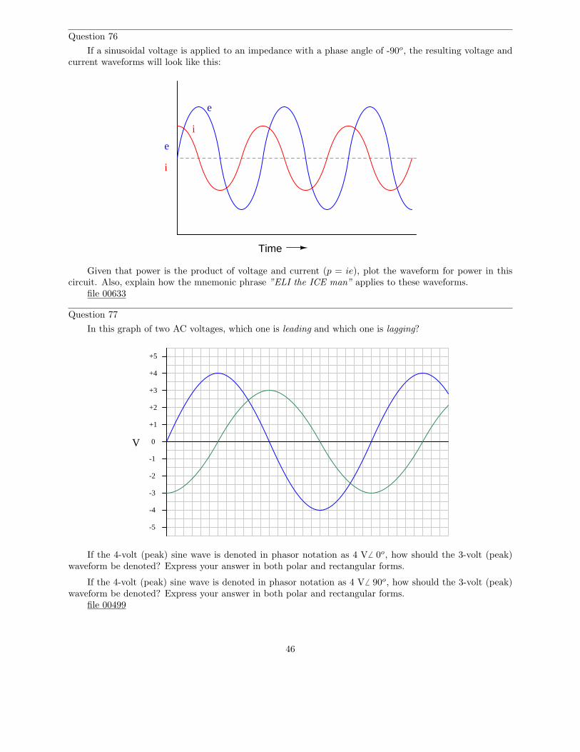
Question 76
If a sinusoidal voltage is applied to an impedance with a phase angle of -90o, the resulting voltage andcurrent waveforms will look like this:
Time
e
i
e
i
Given that power is the product of voltage and current (p = ie), plot the waveform for power in thiscircuit. Also, explain how the mnemonic phrase ”ELI the ICE man” applies to these waveforms.
file 00633
Question 77
In this graph of two AC voltages, which one is leading and which one is lagging?
0
+1
+2
+3
+4
+5
-1
-2
-3
-4
-5
V
If the 4-volt (peak) sine wave is denoted in phasor notation as 4 V6 0o, how should the 3-volt (peak)waveform be denoted? Express your answer in both polar and rectangular forms.
If the 4-volt (peak) sine wave is denoted in phasor notation as 4 V6 90o, how should the 3-volt (peak)waveform be denoted? Express your answer in both polar and rectangular forms.
file 00499
46

Question 78
In this phasor diagram, determine which phasor is leading and which is lagging the other:
A
B
file 03286
Question 79
Large power distribution centers are often equipped with capacitors to correct for lagging (inductive)power factor of many industrial loads. There is never any one value for capacitance that will preciselycorrect for the power factor, though, because load conditions constantly change. At first it may seem thata variable capacitor would be the answer (adjustable to compensate for any value of lagging power factor),but variable capacitors with the ratings necessary for power line compensation would be prohibitively largeand expensive.
One solution to this problem of variable capacitance uses a set of electromechanical relays with fixed-value capacitors:
Relay Relay Relay Relay
1 µF 2 µF 4 µF 8 µF
. . .
. . .
To AC powerlines
Explain how a circuit such as this provides a step-variable capacitance, and determine the range ofcapacitance it can provide.
file 03625
47

Question 80
Lenz’s Law describes the opposition to changes in magnetic flux resulting from electromagnetic inductionbetween a magnetic field and an electrical conductor. One apparatus capable of demonstrating Lenz’s Lawis a copper or aluminum disk (electrically conductive, but non-magnetic) positioned close to the end of apowerful permanent magnet. There is no attraction or repulsion between the disk and magnet when there isno motion, but a force will develop between the two objects if either is suddenly moved. This force will be insuch a direction that it tries to resist the motion (i.e. the force tries to maintain the gap constant betweenthe two objects):
N S
Motion
Reactionforce
We know this force is magnetic in nature. That is, the induced current causes the disk itself to become amagnet in order to react against the permanent magnet’s field and produce the opposing force. For each ofthe following scenarios, label the disk’s induced magnetic poles (North and South) as it reacts to the motionimposed by an outside force:
N S
Motion
N S
Motion
Figure 1 Figure 2
Figure 3 Figure 4
NS
Motion
NS
Motion
file 01982
48

Question 81
Combining Lenz’s Law with the right-hand rule (or left-hand rule, if you follow electron flow instead ofconventional flow) provides a simple and effective means for determining the direction of induced current inan induction coil. In the following examples, trace the direction of current through the load resistor:
Figure 1 Figure 2 Figure 3
Figure 4 Figure 5 Figure 6
NS
MotionNS
Motion
NS
Motion
NS
Motion
NS
Motion
NS
Motion
file 01787
Question 82
Based on your knowledge of Lenz’s Law, explain how one could construct an electromagnetic brake,whereby the energization of an electromagnet coil would produce mechanical ”drag” on a rotating shaftwithout the need for contact between the shaft and a brake pad.
file 01786
49

Question 83
If an electric current is passed through this wire, which direction will the wire be pushed (by theinteraction of the magnetic fields)?
MagnetN S MagnetN S
+-
wire
Is this an example of an electric motor or an electric generator?file 00382
50

Question 84
If this wire (between the magnet poles) is moved in an upward direction, what polarity of voltage willthe meter indicate?
MagnetN S MagnetN Swire
V Ω
COMA
mot
ion
Describe the factors influencing the magnitude of the voltage induced by motion, and determine whetherthis is an example of an electric motor or an electric generator.
file 00806
51
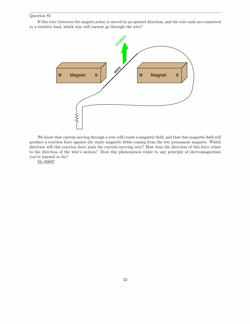
Question 85
If this wire (between the magnet poles) is moved in an upward direction, and the wire ends are connectedto a resistive load, which way will current go through the wire?
MagnetN S MagnetN Swire
mot
ion
We know that current moving through a wire will create a magnetic field, and that this magnetic field willproduce a reaction force against the static magnetic fields coming from the two permanent magnets. Whichdirection will this reaction force push the current-carrying wire? How does the direction of this force relateto the direction of the wire’s motion? Does this phenomenon relate to any principle of electromagnetismyou’ve learned so far?
file 00807
52

Question 86
Determine the polarity of induced voltage between the ends of this wire loop, as it is rotated betweenthe two magnets:
MagnetN S MagnetN S
MagnetN S MagnetN S
MagnetN S MagnetN S
sequ
ence
ove
r tim
e
MagnetN S MagnetN S
MagnetN S MagnetN S
file 00808
53
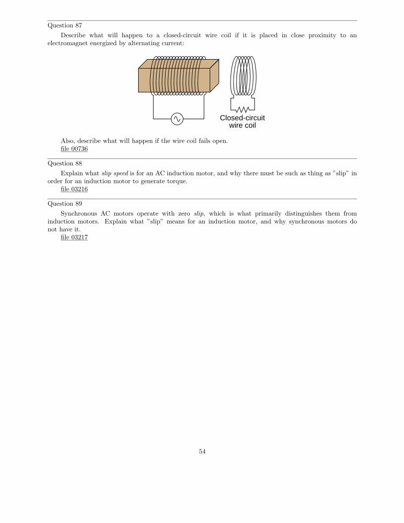
Question 87
Describe what will happen to a closed-circuit wire coil if it is placed in close proximity to anelectromagnet energized by alternating current:
Closed-circuitwire coil
Also, describe what will happen if the wire coil fails open.file 00736
Question 88
Explain what slip speed is for an AC induction motor, and why there must be such as thing as ”slip” inorder for an induction motor to generate torque.
file 03216
Question 89
Synchronous AC motors operate with zero slip, which is what primarily distinguishes them frominduction motors. Explain what ”slip” means for an induction motor, and why synchronous motors donot have it.
file 03217
54
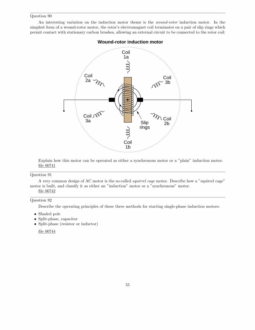
Question 90
An interesting variation on the induction motor theme is the wound-rotor induction motor. In thesimplest form of a wound-rotor motor, the rotor’s electromagnet coil terminates on a pair of slip rings whichpermit contact with stationary carbon brushes, allowing an external circuit to be connected to the rotor coil:
1a
1b
2a
2b3a
3b
Coil
Coil
Coil
CoilCoil
Coil
Sliprings
Wound-rotor induction motor
Explain how this motor can be operated as either a synchronous motor or a ”plain” induction motor.file 00741
Question 91
A very common design of AC motor is the so-called squirrel cage motor. Describe how a ”squirrel cage”motor is built, and classify it as either an ”induction” motor or a ”synchronous” motor.
file 00742
Question 92
Describe the operating principles of these three methods for starting single-phase induction motors:
• Shaded pole• Split-phase, capacitor• Split-phase (resistor or inductor)
file 00744
55
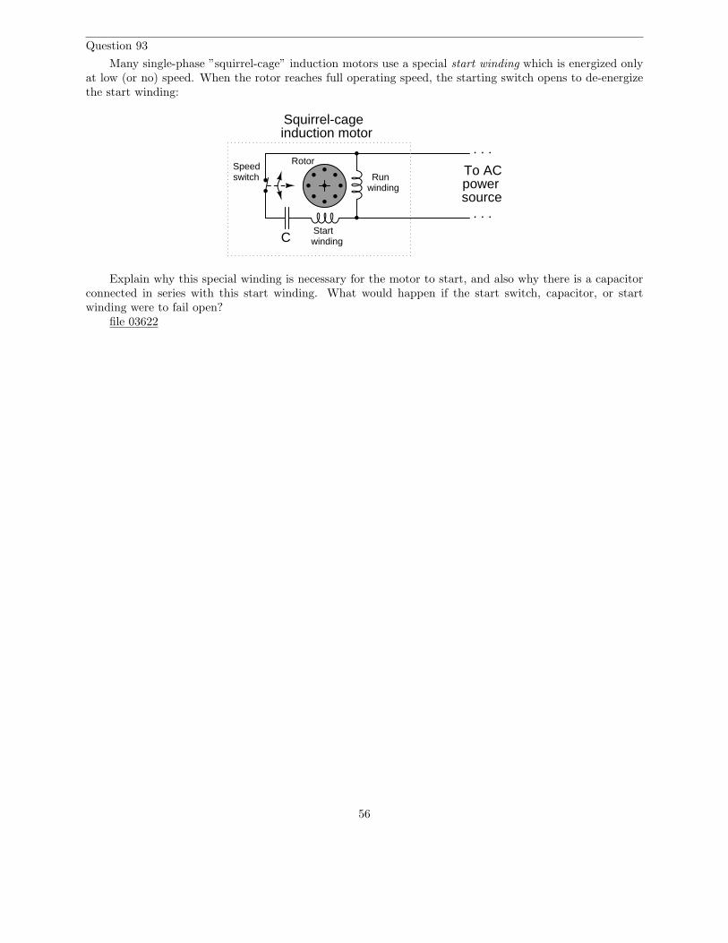
Question 93
Many single-phase ”squirrel-cage” induction motors use a special start winding which is energized onlyat low (or no) speed. When the rotor reaches full operating speed, the starting switch opens to de-energizethe start winding:
Squirrel-cageinduction motor
Speedswitch
CStartwinding
Runwinding
To AC powersource
. . .
. . .
Rotor
Explain why this special winding is necessary for the motor to start, and also why there is a capacitorconnected in series with this start winding. What would happen if the start switch, capacitor, or startwinding were to fail open?
file 03622
56
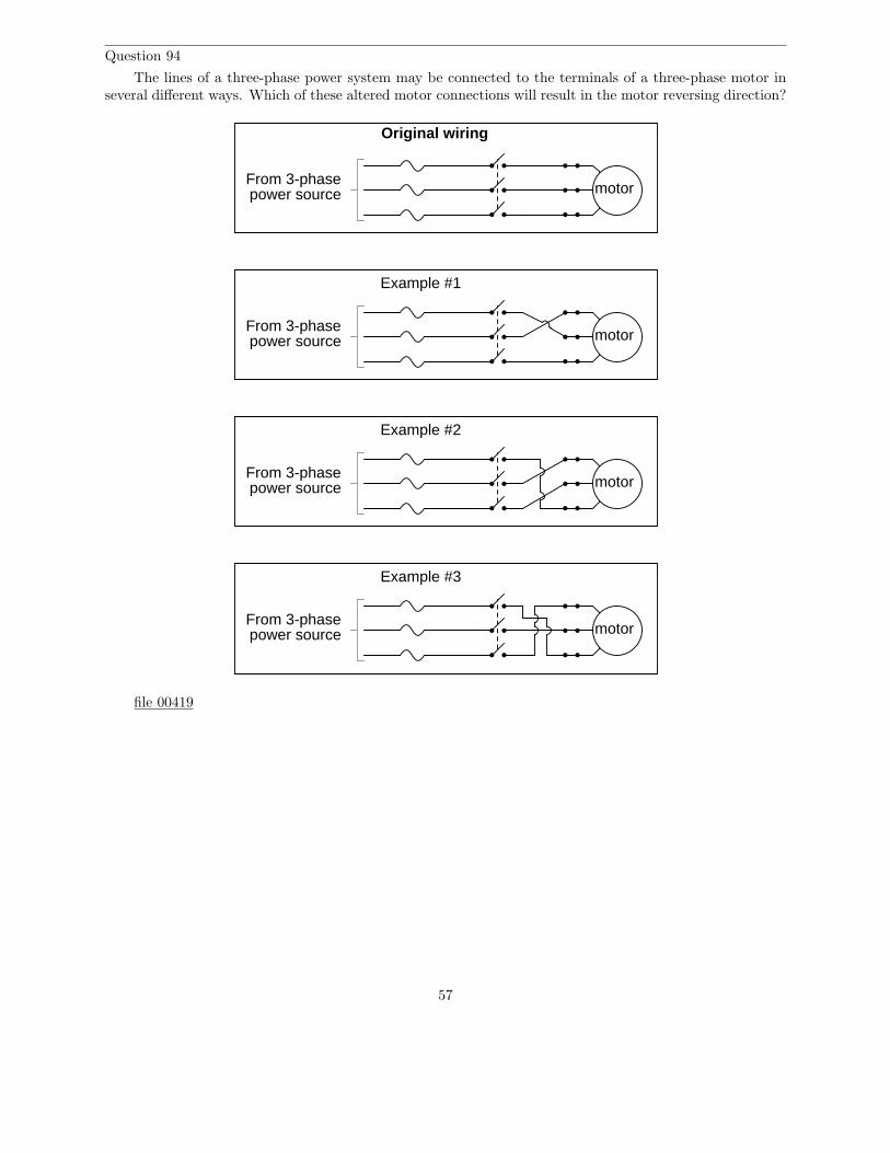
Question 94
The lines of a three-phase power system may be connected to the terminals of a three-phase motor inseveral different ways. Which of these altered motor connections will result in the motor reversing direction?
motorFrom 3-phasepower source
Original wiring
motorFrom 3-phasepower source
motorFrom 3-phasepower source
motorFrom 3-phasepower source
Example #1
Example #2
Example #3
file 00419
57

Question 95
Some AC induction motors are equipped with multiple windings so they may operate at two distinctspeeds (low speed usually being one-half of high speed). Shown here is the connection diagram for one typeof two-speed motor:
1
4
5 62
3
There are six terminals on the motor itself where the connections are made:
1 2 3
4 5 6
Motor
Shaft
The motor’s datasheet will specify how the connections are to be made. This is typical:
Speed φ-A φ-B φ-C Left open Shorted togetherLow 1 2 3 4,5,6High 4 5 6 1,2,3
Explain why the motor runs at half-speed in one connection scheme and full speed in the other. Whatis going on that makes this possible?
file 03218
58

Question 96
This electric motor was operating just fine, then one day it mysteriously shut down. The electriciandiscovered two blown fuses, which he then replaced:
motor
On/off switch
From 3-phasepower source
blown!
blown!
When the on/off switch was closed again, the motor made a loud ”humming” noise, then became quietafter a few seconds. It never turned, though. Upon inspection, the electrician discovered the same two fuseshad blown again.
If you were asked to help troubleshoot this electric motor circuit, what would you recommend as thenext step?
file 00422
59

Question 97
Examine this three-phase motor control circuit, where fuses protect against overcurrent and a three-polerelay (called a contactor) turns power on and off to the motor:
Fuse
Motor
Shaft
Fuse Fuse
1 2 3
1 2 3
Contactor
123
motor
Schematicdiagram
1 2 3
1 2 3
Fuses
After years of faithful service, one day this motor refuses to start. It makes a ”humming” sound when thecontactor is energized (relay contacts close), but it does not turn. A mechanic checks it out and determinesthat the shaft is not seized, but is free to turn. The problem must be electrical in nature!
You are called to investigate. Using a clamp-on ammeter, you measure the current through each ofthe lines (immediately after each fuse) as another start is once again attempted. You then record the threecurrent measurements:
Line Current1 52.7 amps2 51.9 amps3 0 amps
Determine at least two possible faults which could account for the motor’s refusal to start and the
60

three current measurements taken. Then, decide what your next measurement(s) will be to isolate the exactlocation and nature of the fault.
file 03623
Question 98
Working on a job site with an experienced technician, you are tasked with trying to determine whetherthe line currents going to a three-phase electric motor are balanced. If everything is okay with the motorand the power circuitry, of course, the three line currents should be precisely equal to each other.
The problem is, neither of you brought a clamp-on ammeter for measuring the line currents. Yourmultimeters are much too small to measure the large currents in this circuit, and connecting an ammeterin series with such a large motor could be dangerous anyway. So, the experienced technician decides to trysomething different – he uses his multimeter as an AC milli-voltmeter to measure the small voltage dropacross each fuse, using the fuses as crude shunt resistors:
Fuse Fuse FuseOFF
COMA
V A
V A
mV
He obtains the following measurements:
Line Fuse voltage drop1 24.3 mV2 37.9 mV3 15.4 mV
Do these voltage drop measurements suggest imbalanced motor line currents? Why or why not?file 03624
61

Question 99
How is polyphase (especially three-phase) electric power generated? Single-phase power is easy tounderstand, but how do we create three-phase AC voltage?
file 00416
Question 100
What is meant by the term phase rotation sequence, in a polyphase electrical system?file 00417
Question 101
Suppose the electrical power supplied to a commercial building is labeled as ”208/120 volt”. What doesthis label mean, exactly? Relate this description to a schematic diagram.
file 00420
62

Question 102
Suppose you are working on the power wiring inside of a home, and are wondering whether or not thehome is supplied with 3-phase or single-phase power. You do not have a voltmeter available to measurevoltage, but you do have plenty of light bulbs, switches, wires, and other standard residential wiringcomponents available for use.
The two possibilities for this home’s power source are shown here, the coils representing secondarywindings of the utility power transformer:
NeutralLine Line
3-phase
NeutralLine Line
Single-phase
???
An experienced electrician suggests you build the following circuit to test whether or not the home’spower is supplied by a 3-phase source or a single-phase source:
Main circuitbreaker
Line Line Neutral
. . .
. . .
. . .
Test circuit
The electrician tells you to open and close the switch, and observe the brightness of the light bulbs.This will indicate whether or not the system is 3-phase.
Explain how this circuit works. What sort of light bulb behavior would indicate a 3-phase source? Whatsort of light bulb behavior would indicate a single-phase source?
file 00413
63

Question 103
This Delta-connected three-phase power source provides three different voltage levels: 120 V, 208 V,and 240 V. Determine which points of connection provide these voltages:
A
B
C
G
file 01058
Question 104
Explain the difference between a balanced polyphase system and an unbalanced polyphase system. Whatconditions typically cause a polyphase system to become unbalanced?
file 00418
Question 105
In a balanced Y-connected power system, calculate the phase voltage (Ephase) if the line voltage (Eline)is 480 volts.
file 00412
Question 106
What resistor values would we have to choose in a Delta configuration to behave exactly the same asthis Y-connected resistor network?
300 Ω 300 Ω
300 Ω
file 00429
64

Question 107
What will happen in each of these systems to the phase voltages of the load, if one of the source phasesfails open?
Source Load
Windingfails open!
Source Load
Windingfails open!
file 00423
65

Question 108
Identify the primary-secondary connection configuration of these three power transformers (i.e. Y-Y,Y-Delta, Delta-Y, etc.):
A B C
a b c
H1H2 H2 H1 H2 H1
X1X2 X1X2 X1X2
Primary side
Secondary side
file 01889
66

Question 109
An electrical lineman is connecting three single-phase transformers in a Y(primary)-Y(secondary)configuration, for power service to a business. Draw the connecting wires necessary between the transformerwindings, and between the transformer terminals and the lines:
Pow
er pole
crossarm
insulator
power line
Transformer Transformer Transformer
Low-voltage linesto customer
Note: fuses have been omitted from this illustration, for simplicity.file 00424
67
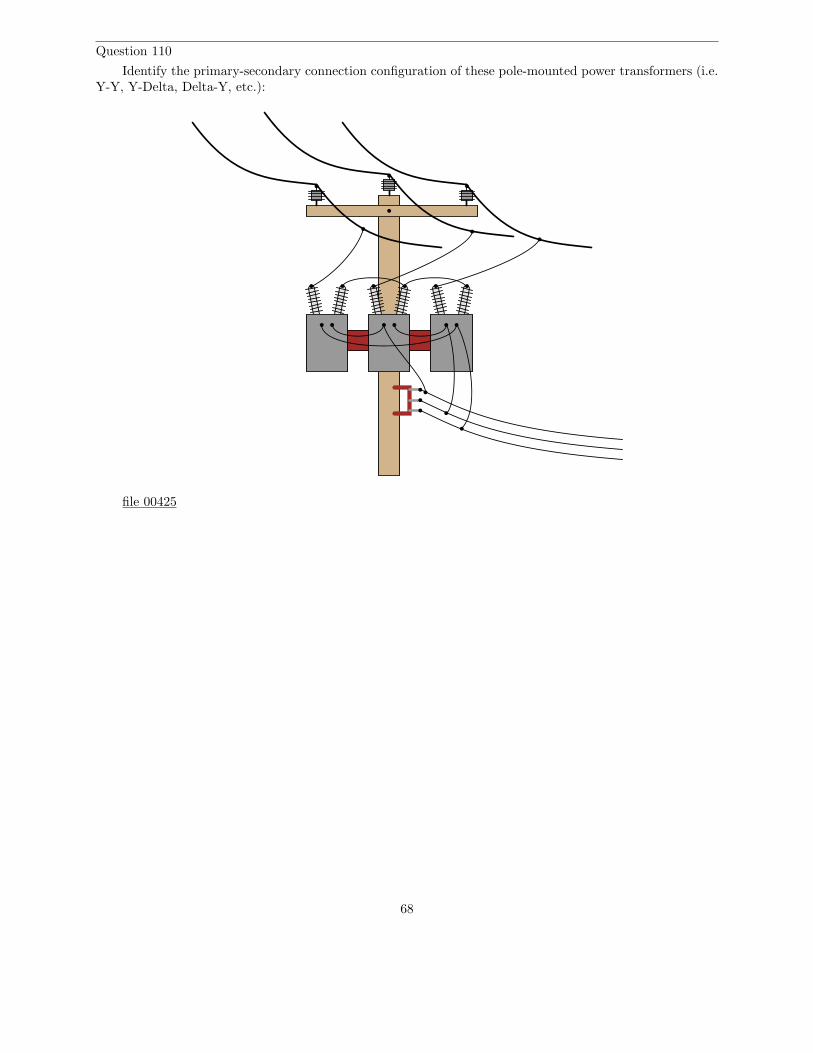
Question 110
Identify the primary-secondary connection configuration of these pole-mounted power transformers (i.e.Y-Y, Y-Delta, Delta-Y, etc.):
file 00425
68

Question 111
Identify the primary-secondary connection configuration of these pole-mounted power transformers (i.e.Y-Y, Y-Delta, Delta-Y, etc.):
file 00427
69
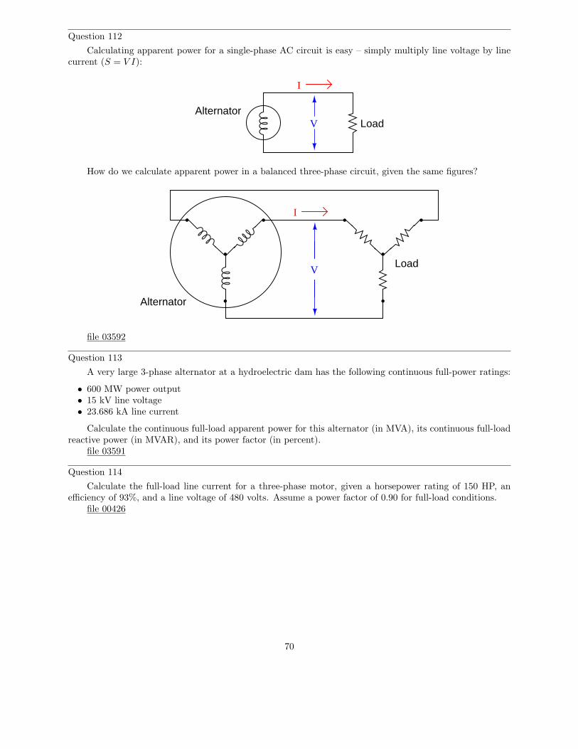
Question 112
Calculating apparent power for a single-phase AC circuit is easy – simply multiply line voltage by linecurrent (S = V I):
AlternatorLoadV
I
How do we calculate apparent power in a balanced three-phase circuit, given the same figures?
V
I
Alternator
Load
file 03592
Question 113
A very large 3-phase alternator at a hydroelectric dam has the following continuous full-power ratings:
• 600 MW power output• 15 kV line voltage• 23.686 kA line current
Calculate the continuous full-load apparent power for this alternator (in MVA), its continuous full-loadreactive power (in MVAR), and its power factor (in percent).
file 03591
Question 114
Calculate the full-load line current for a three-phase motor, given a horsepower rating of 150 HP, anefficiency of 93%, and a line voltage of 480 volts. Assume a power factor of 0.90 for full-load conditions.
file 00426
70

Answers
Answer 1
P = 264 Watts
If the source is a chemical battery, energy comes from the chemical reactions occurring in the battery’selectrolyte, becomes transfered to electrical form, and then converted to heat and light in the bulb, all atthe rate of 264 Joules per second (J/s).
Answer 2
The energy consumed by the load must be supplied by whatever mechanical source turns the generator.In this case, the source is the human being pedaling the bicycle.
Follow-up question: what would it mean if a generator required no physical effort to turn while it waspowering an electrical load?
Answer 3
Positive power represents energy flowing from the source to the (resistive) load, in this case meaningthat energy never returns from the load back to the source.
Answer 4
A symmetrically oscillating power waveform represents energy going back and forth between source andload, never actually dissipating.
Answer 5
The inductor can only store and release energy, not dissipate it. Therefore, its actual power dissipationis zero!
Answer 6
I = 141.18 AP = 90.8 horsepower
Answer 7
I = 141.18 AP = 0 horsepower, so long as the inductor is ”pure” (100 percent inductance, with no resistance).
71
Answer 8
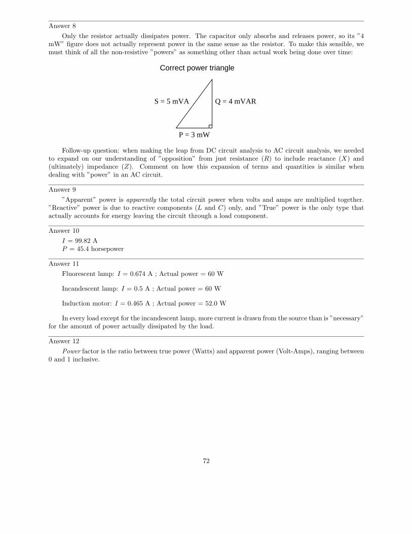
Only the resistor actually dissipates power. The capacitor only absorbs and releases power, so its ”4mW” figure does not actually represent power in the same sense as the resistor. To make this sensible, wemust think of all the non-resistive ”powers” as something other than actual work being done over time:
Q = 4 mVAR
P = 3 mW
S = 5 mVA
Correct power triangle
Follow-up question: when making the leap from DC circuit analysis to AC circuit analysis, we neededto expand on our understanding of ”opposition” from just resistance (R) to include reactance (X) and(ultimately) impedance (Z). Comment on how this expansion of terms and quantities is similar whendealing with ”power” in an AC circuit.
Answer 9
”Apparent” power is apparently the total circuit power when volts and amps are multiplied together.”Reactive” power is due to reactive components (L and C) only, and ”True” power is the only type thatactually accounts for energy leaving the circuit through a load component.
Answer 10
I = 99.82 AP = 45.4 horsepower
Answer 11
Fluorescent lamp: I = 0.674 A ; Actual power = 60 W
Incandescent lamp: I = 0.5 A ; Actual power = 60 W
Induction motor: I = 0.465 A ; Actual power = 52.0 W
In every load except for the incandescent lamp, more current is drawn from the source than is ”necessary”for the amount of power actually dissipated by the load.
Answer 12
Power factor is the ratio between true power (Watts) and apparent power (Volt-Amps), ranging between0 and 1 inclusive.
72
Answer 13
S = IV S = I2Z S =V 2
ZApparent power in AC circuits
P = IV cos Θ P = I2R P =V 2
RTrue power in AC circuits
Q = IV sinΘ Q = I2X Q =V 2
XReactive power in AC circuits
Follow-up question #1: algebraically manipulate each of the following equations to solve for all theother variables in them:
Q = I2X S =V 2
ZP = I2R
Follow-up question #2: substitute π, f , and either L or C into the reactive power equations so that onemay calculate Q without having to directly know the value of X.
Answer 14
P.F. = 0.872
Answer 15
A leading power factor is one created by a predominantly capacitive load, whereas a lagging power factoris one created by a predominantly inductive load.
Answer 16
Fluorescent lamp: P = 60 W ; Q = 54.3 VAR ; S = 80.9 VA ; PF = 0.74, leading
Incandescent lamp: P = 60 W ; Q = 0 VAR ; S = 60 VA ; PF = 1.0
Induction motor: P = 52.0 W ; Q = 20.4 VAR ; S = 55.8 VA ; PF = 0.93, lagging
Answer 17
Θ = arccos(PF ) = 14.1o
Answer 18
The beer itself is ”true” power (P , measured in Watts). Good beer, good. Ideally, we’d like to havea full mug of beer (true power). Unfortunately, we also have foam in the mug, representing ”reactive”power (Q, measured in Volt-Amps-Reactive), which does nothing but occupy space in the mug. Bad foam,bad. Together, their combined volume constitutes the ”apparent” power in the system (S, measured inVolt-Amps).
Follow-up question: can you think of any potential safety hazards that low power factor may present ina high-power circuit? We’re talking AC power circuits here, not beer!
73
Answer 19
Use an oscilloscope to measure the circuit’s Θ (phase shift between voltage and current), and thencalculate the power factor from that angle.
Follow-up question #1: explain how you could safely measure currents in the range of hundreds orthousands of amps, and also measure voltages in the range of hundreds or thousands of volts, using anoscilloscope. Bear in mind that you need to simultaneously plot both variables on the oscilloscope in orderto measure phase shift!
Follow-up question #2: explain how you could measure either S, Q, or P using a multimeter.
Answer 20
P.F. = 1 ; current = 72.98 amps
P.F. = 0.65 ; current = 112.3 amps
Follow-up question: what is the ”extra” current in the 0.65 power factor scenario doing, if notcontributing to the motor’s mechanical power output?
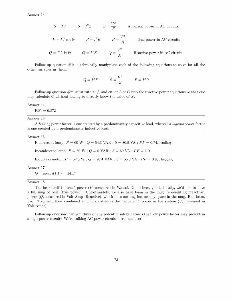
Answer 21
0 degrees phase shift 90 degrees phase shift
Challenge question: what kind of Lissajous figures would be plotted by the oscilloscope if the signalswere non-sinusoidal? Perhaps the simplest example of this would be two square waves instead of two sinewaves.
Answer 22
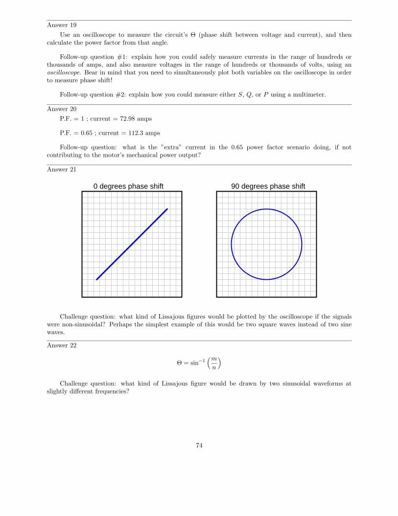
Θ = sin−1(m
n
)
Challenge question: what kind of Lissajous figure would be drawn by two sinusoidal waveforms atslightly different frequencies?
74

Answer 23
Θ ≈ 57o P.F. ≈ 0.54
Follow-up question: is this the only way we could have used the oscilloscope to measure phase shiftbetween voltage and current, or is there another mode of operation besides plotting Lissajous figures?
Answer 24
P.F. ≈ 0.84, lagging (most likely)
Follow-up question: is it possible to determine which waveform is leading or lagging the other from aLissajous figure? Explain your answer.
Answer 25
P.F. = 0.897 Θ = 26.23o
P = 155 kW
S = 172.8 kVA
θ = 26.23o
Answer 26
Without capacitor• S = 1.432 VA• P = 0 W• Q = 1.432 VAR
With capacitor• S = 0.369 VA• P = 0 W• Q = 0.369 VAR
Answer 27
Without capacitor• Iline = 48 A• P.F. = 0.829
With capacitor• Iline = 39.87 A• P.F. = 0.998
Follow-up question: does the addition of the capacitor affect the amount of current through the 5 Ωload? Why or why not?
Answer 28
Low power factors result in excessive line current.
75

Answer 29
As power factor is brought closer to unity (1), the power triangle ”flattens,” with P remaining constant:
P
QS
θ
Answer 30
QC =E2
XC
QC = I2XC
Follow-up question: which of the two equations shown above would be easiest to use in calculating thereactive power of a capacitor given the following information?
Inductive load
(lagging Q)
Capacitor(leading Q)
I = 3.7 A
V = 120 V XC
I = 4.1 A
Answer 31
• Apparent power (S) = 2.787 kVA• True power (P ) = 2.567 kW• Reactive power (Q) = 1.089 kVAR• Power factor = 0.921• Correction capacitor value = 66.77 µF
Challenge question: write an equation solving for the power factor correction capacitor size (in Farads)given any or all of the variables provided in the question (S, P , Q, f , V , P.F.).
Answer 32
• Apparent power (S) = 72.45 kVA• True power (P ) = 52.89 kW• Reactive power (Q) = 49.52 kVAR• Θ = 43.11o
• Necessary parallel C size to correct power factor to unity = 2,483 µF
Answer 33
76

• Apparent power (S) = 17.23 MVA• Reactive power (Q) = 8.107 MVAR• Power factor = 0.882• Θ = 28.1o
• Necessary parallel C size to correct power factor to unity = 1.951 µF
Answer 34
• Apparent power (S) = 352 VA• True power (P ) = 328.2 W• Reactive power (Q) = 127.2 VAR• Θ = 21.2o
• Power factor = 0.932• Necessary parallel C size to correct power factor to unity = 27.9 µF
Follow-up question: identify which waveform represents voltage and which waveform represents currenton the oscilloscope display.
77

Answer 35
Uncorrected power factor = 0.707, lagging
Alternator
480 VAC60 Hz
9.02 mH
3.4 Ω390 µF
Follow-up question: when we use capacitors as power factor correction components in an AC powersystem, the equivalent series resistance (ESR) inside the capacitor becomes a significant factor:
Equivalent Series Resistance (ESR)
Ideal capacitor
Realcapacitor
Current through this equivalent series resistance produces heat, and when we’re dealing with MVARsworth of reactive power in high-current circuits, this heat can be substantial unless ESR is held low by specialcapacitor designs. Describe some possible hazards of excessive ESR for a power factor correction capacitorin a high-current circuit.
Challenge question: the ideal location for power factor correction capacitors is at the load terminals,where the reduction in current will be ”felt” by all components in the system except the load itself. However,in real life, power factor correction capacitors are often located at the power plant (the alternator). Whywould anyone choose to locate capacitors there? What benefit would they provide at all, in that location?
Answer 36
I’ll let you determine your own procedure, based on the steps you had to take to correct power factorin other questions!
Power factor correction calculation procedure••••••
78

Answer 37
This is essentially a series-resonant circuit, with all the inherent dangers of series resonance (I’ll let youreview what those dangers are!).
Follow-up question: aside from safety, there is also the matter of reliability that concerns us. Examine theparallel-capacitor circuit and the series-capacitor circuit from the perspective of a failed capacitor. Explainhow each type of capacitor failure (open versus short) will affect these two circuits.
Answer 38
If inductive loads have their low power factors corrected by the addition of parallel capacitors, thesolution to correcting low power factor for a capacitive load should be easy to identify. I’ll let you figure outthe answer to this!
Challenge question: explain how you could exploit the inductive nature of electric motors and othermore common load devices in correcting for an excessively low leading power factor.
Answer 39
It is true that inductors and capacitors alike neither dissipate nor generate electrical energy. They do,however, store and release energy. And they do so in complementary fashion, inductors storing energy atthe same time that capacitors release, and visa-versa.
Part of the answer to this question lies in the fact that most large AC loads are inductive in nature.From a power plant’s perspective, the reactive power of a customer (a ”consumer” of power) is inductive innature, and so that form of reactive power would naturally be considered ”consumption.”
Answer 40
A ”synchronous condenser” is a special type of AC electric motor that happens to have a variable powerfactor. They are used as variable capacitors to correct for changing power factors.
Challenge question: capacitors are considered reactive devices because they have to ability to store andrelease energy. How would a synchronous condenser store and release energy, seeing as it does not make useof electric fields as capacitors do?
Answer 41
The answer to this question is easy enough to determine experimentally. I’ll let you discover it foryourself rather than give you the answer here.
Hint: the voltage generated by a magnetic field with a single wire is quite weak, so I recommend usinga very sensitive voltmeter and/or a powerful magnet. Also, if the meter is analog (has a moving pointer anda scale rather than a digital display), you must keep it far away from the magnet, so that the magnet’s fielddoes not directly influence the pointer position.
Follow-up question: identify some potential problems which could arise in this experiment to preventinduction from occurring.
79
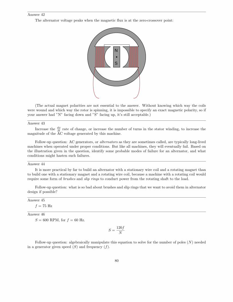
Answer 42
The alternator voltage peaks when the magnetic flux is at the zero-crossover point:
N
S
(The actual magnet polarities are not essential to the answer. Without knowing which way the coilswere wound and which way the rotor is spinning, it is impossible to specify an exact magnetic polarity, so ifyour answer had ”N” facing down and ”S” facing up, it’s still acceptable.)
Answer 43
Increase the dφdt
rate of change, or increase the number of turns in the stator winding, to increase themagnitude of the AC voltage generated by this machine.
Follow-up question: AC generators, or alternators as they are sometimes called, are typically long-livedmachines when operated under proper conditions. But like all machines, they will eventually fail. Based onthe illustration given in the question, identify some probable modes of failure for an alternator, and whatconditions might hasten such failures.
Answer 44
It is more practical by far to build an alternator with a stationary wire coil and a rotating magnet thanto build one with a stationary magnet and a rotating wire coil, because a machine with a rotating coil wouldrequire some form of brushes and slip rings to conduct power from the rotating shaft to the load.
Follow-up question: what is so bad about brushes and slip rings that we want to avoid them in alternatordesign if possible?
Answer 45
f = 75 Hz
Answer 46
S = 600 RPM, for f = 60 Hz.
S =120f
N
Follow-up question: algebraically manipulate this equation to solve for the number of poles (N) neededin a generator given speed (S) and frequency (f).
80
Answer 47
8 poles, which is the same as 4 pole pairs.
Follow-up question: algebraically manipulate the speed/poles/frequency equation to solve for thefrequency generated (f) given the number of poles (N) and the generator speed (S).
Answer 48
The rotor cannot be a permanent magnet, but must be an electromagnet, where we can change itsmagnetic field strength at will.
Follow-up question: how is it possible to conduct electric power to windings on a spinning rotor? Shouldwe energize the rotor winding with AC or DC? Explain your answer.
Answer 49
The lamps will blink from left to right (C-B-A-C-B-A).
Follow-up question: suppose lamp B stopped blinking, while lamps A and C continued. Identify atleast two possible causes for this failure.
Answer 50
99 volts
Hint: if you don’t understand how this voltage value was calculated, plot the voltage output of the twowindings as if they were shown on an oscilloscope. The phase relationship between the two voltages is keyto the solution.
Follow-up question: draw a phasor diagram showing how the difference in potential (voltage) betweenthe wire ends is equal to 99 volts, when each winding coil’s voltage is 70 volts.
Answer 51
121.2 volts
Follow-up question: draw a phasor diagram showing how the difference in potential (voltage) betweenthe wire ends is equal to 121.2 volts, when each winding coil’s voltage is 70 volts.
Answer 52
In polyphase systems, there are multiple voltages phase-shifted apart from each other so as to beintentionally ”out of step.”
81

Answer 53
Vphase
Vline
Iphase
Iphase
I phas
e
Iline I line
I line
Iline I line
I line
Iphase
Iphase
I phas
e
Vphase Vphase
V phas
e
Vphase
VphaseVline
Vline
VlineVline
Vline
Y configuration• Iphase = Iline
• Vphase < Vline
Delta configuration• Vphase = Vline
• Iphase < Iline
Follow-up question: how do Kirchhoff’s Voltage and Current Laws explain the relationships betweenunequal quantities in ”Y” and ”Delta” configurations?
82

Answer 54
Phase voltage = 277 volts AC (given)Line voltage = VAB = VBC = VAC = 480 volts AC
VA = 277 V
V B =
277
V
VC = 277 V
V AB = 480 V
VB
C =
480
V
VAC = 480 V
120o
120o
120 o
Follow-up question #1: what is the ratio between the line and phase voltage magnitudes in a Y-connectedthree-phase system?
Follow-up question #2: what would happen to the output of this alternator if the rotor winding were tofail open? Bear in mind that the rotor winding is typically energized with DC through a pair of brushes andslip rings from an external source, the current through this winding being used to control voltage output ofthe alternator’s three-phase ”stator” windings.
Answer 55
Phase current = 17 amps AC (given)Line current = IA = IB = IC = 29.4 amps AC
Follow-up question #1: what is the ratio between the line and phase current magnitudes in a Delta-connected three-phase system?
Follow-up question #2: what would happen to the output of this alternator if the rotor winding were tofail open? Bear in mind that the rotor winding is typically energized with DC through a pair of brushes andslip rings from an external source, the current through this winding being used to control voltage output ofthe alternator’s three-phase ”stator” windings.
Answer 56
The phenomenon is known as Lenz’ Law. If the copper ring is moved away from the end of the permanentmagnet, the direction of force will reverse and become attractive rather than repulsive.
Follow-up question: trace the direction of rotation for the induced electric current in the ring necessaryto produce both the repulsive and the attractive force.
Challenge question: what would happen if the magnet’s orientation were reversed (south pole on leftand north pole on right)?
83
Answer 57
The phenomenon is known as Lenz’ Law, and it exists only when there is a continuous path for current(i.e. a complete circuit) in the wire coil.
Answer 58
This is an example of Lenz’ Law. A rotating magnet would cause a torque to be generated in the disk.
Answer 59
If arranged in a circle, the lights would appear to rotate. The speed of this ”rotation” depends on thefrequency of the on/off blinking.
Follow-up question: what electrical change(s) would you have to make to reverse the direction of thelights’ apparent motion?
Challenge question: what would happen to the apparent motion of the lights if one of the phases (either1, 2, or 3) were to fail, so that none of the bulbs with that number would ever light up?
Answer 60
The compass needle would rotate.
Challenge question: what would happen to the apparent motion of the magnetic field if one of the phases(either 1, 2, or 3) were to fail, so that none of the coils with that number would ever energize?
Answer 61
The rotor will rotate due to the action of Lenz’s Law.
Follow-up question: what would happen if the rotor’s coil were to become open-circuited?
Answer 62
Synchronous motors rotate in ”sync” to the power line frequency. Induction motors rotate a bit slower,their rotors always ”slipping” slightly slower than the speed of the rotating magnetic field.
Challenge question: what would happen if an induction motor were mechanically brought up to speedwith its rotating magnetic field? Imagine using an engine or some other prime-mover mechanism to force theinduction motor’s rotor to rotate at synchronous speed, rather than ”slipping” behind synchronous speed asit usually does. What effect(s) would this have?
Answer 63
Reverse any two lines. This will reverse the phase sequence (from ABC to CBA).
84
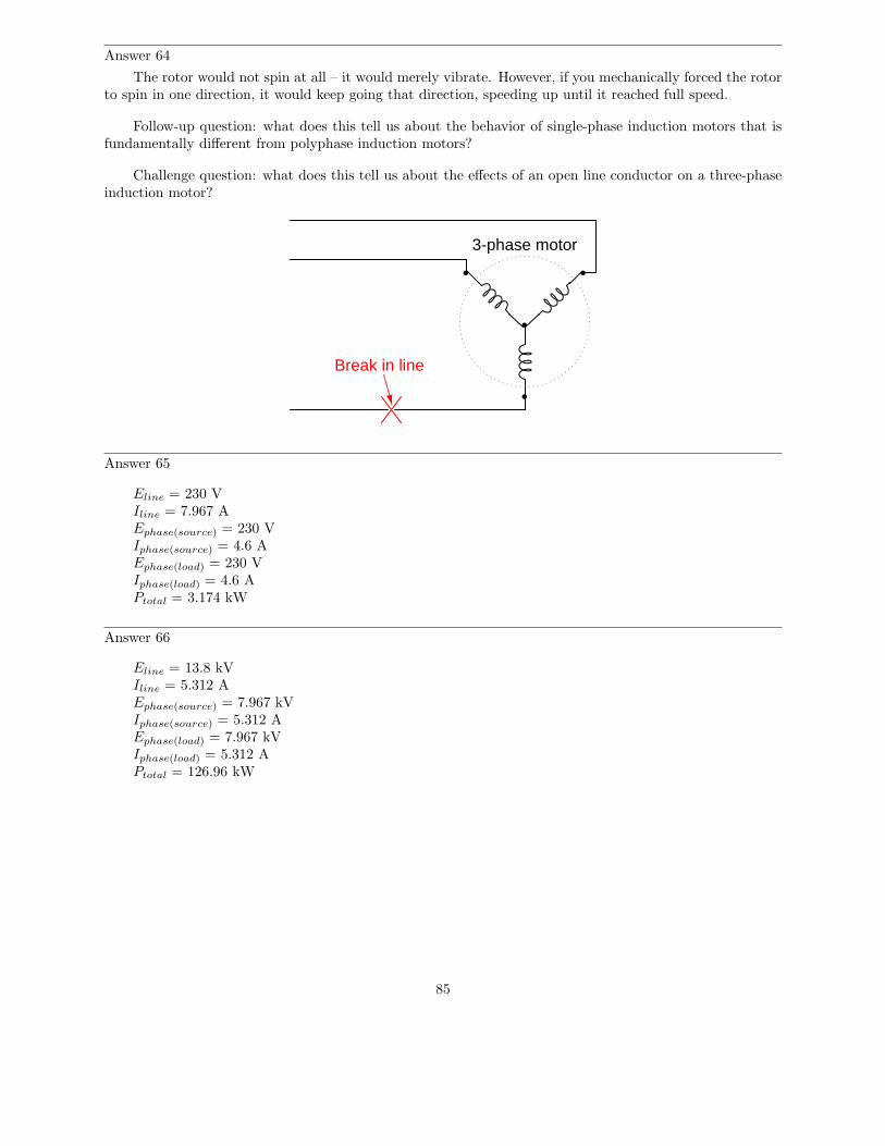
Answer 64
The rotor would not spin at all – it would merely vibrate. However, if you mechanically forced the rotorto spin in one direction, it would keep going that direction, speeding up until it reached full speed.
Follow-up question: what does this tell us about the behavior of single-phase induction motors that isfundamentally different from polyphase induction motors?
Challenge question: what does this tell us about the effects of an open line conductor on a three-phaseinduction motor?
3-phase motor
Break in line
Answer 65
Eline = 230 VIline = 7.967 AEphase(source) = 230 VIphase(source) = 4.6 AEphase(load) = 230 VIphase(load) = 4.6 APtotal = 3.174 kW
Answer 66
Eline = 13.8 kVIline = 5.312 AEphase(source) = 7.967 kVIphase(source) = 5.312 AEphase(load) = 7.967 kVIphase(load) = 5.312 APtotal = 126.96 kW
85

Answer 67
Eline = 2400 VIline = 4.619 AEphase(source) = 2400 VIphase(source) = 2.667 AEphase(load) = 1385.6 VIphase(load) = 4.619 APtotal = 19.2 kW
Answer 68
Eline = 207.8 VIline = 0.621 AEphase(source) = 120 VIphase(source) = 0.621 AEphase(load) = 207.8 VIphase(load) = 0.358 APtotal = 223.4 W
Answer 69
Ptotal = 27.648 kWIline = 33.255 A
I’ll let you derive your own equation for power calculation. Be ready to show your work!
Answer 70
Pload = 3.59 MW
A single-phase system operating at 13.8 kV would require at least 1/0 (”one-ought”) gauge copperconductors to transmit 3.59 MW of power. A three-phase system operating at the same voltage wouldrequire at least #2 gauge copper conductors.
Answer 71
Use circuit simulation software to verify your predicted and measured parameter values.
Answer 72
The meter measurements you take will constitute the “final word” for validating your predictions.
Answer 73
Be sure you meet with your instructor if you have any questions about what is expected for your project!
86

Answer 74
Time
e
i
ei p
Answer 75
Time
e
i
e
ip
The mnemonic phrase, ”ELI the ICE man” indicates that this phase shift is due to an inductance ratherthan a capacitance.
87

Answer 76
Time
e
i
e
ip
The mnemonic phrase, ”ELI the ICE man” indicates that this phase shift is due to a capacitance ratherthan an inductance.
Answer 77
The 4-volt (peak) waveform leads the 3-volt (peak) waveform. Conversely, the 3-volt waveform lagsbehind the 4-volt waveform.
If the 4-volt waveform is denoted as 4 V 6 0o, then the 3-volt waveform should be denoted as 3 V 6
-90o, or 0 − j3 V.
If the 4-volt waveform is denoted as 4 V 6 90o (0+ j4 V in rectangular form), then the 3-volt waveformshould be denoted as 3 V 6 0o, or 3 + j0 V.
Answer 78
In this diagram, phasor B is leading phasor A.
Follow-up question: using a protractor, estimate the amount of phase shift between these two phasors.
Answer 79
Capacitors may be selected in combination to provide anywhere from 0 µF to 15 µF, in 1 µF steps.
88

Answer 80
The disk’s own magnetic field will develop in such a way that it ”fights” to keep a constant distancefrom the magnet:
N S
Motion
N S
Motion
Figure 1 Figure 2
Figure 3 Figure 4
NS
Motion
NS
Motion
N S N S
NS N S
Follow-up question: trace the direction of rotation for the induced electric current in the disk necessaryto produce both the repulsive and the attractive force.
89

Answer 81
Note: in case it isn’t clear from the illustrations, Figures 1 through 4 show the magnet moving in relationto a stationary coil. Figures 5 and 6 show a coil moving in relation to a stationary magnet.
Figure 1 Figure 2 Figure 3
Figure 4 Figure 5 Figure 6
NS
MotionNS
Motion
NS
Motion
NS
Motion
NS
Motion
NS
Motion
Note: all current directions shown using conventional flow notation(following the right-hand rule)
Answer 82
shaft
Conductive disk
Electromagnet
Follow-up question: describe some of the advantages and disadvantages that a magnetic brake wouldhave, compared to mechanical brakes (where physical contact produces friction on the shaft).
Challenge question: normal (mechanical) brakes become hot during operation, due to the friction theyemploy to produce drag. Will an electromechanical brake produce heat as well, given that there is no physicalcontact to create friction?
90

Answer 83
The wire will be pushed up in this motor example.
Answer 84
The voltmeter will indicate a negative voltage in this generator example.
Answer 85
The reaction force will be directly opposed to the direction of motion, as described by Lenz’s Law.
Follow-up question: What does this phenomenon indicate to us about the ease of moving a generatormechanism under load, versus unloaded? What effect does placing an electrical load on the output terminalsof a generator have on the mechanical effort needed to turn the generator?
91

Answer 86
MagnetN S MagnetN S
MagnetN S MagnetN S
MagnetN S MagnetN S
sequ
ence
ove
r tim
e
MagnetN S MagnetN S
MagnetN S MagnetN S
Challenge question: if a resistor were connected between the ends of this wire loop, would it ”see” directcurrent (DC), or alternating current (AC)?
Answer 87
The wire coil will vibrate as it is alternately attracted to, and repelled by, the electromagnet. If the coilfails open, the vibration will cease.
Challenge question: how could we vary the coil’s vibrational force without varying the amplitude of theAC power source?
92

Answer 88
The difference between the speed of the rotating magnetic field (fixed by line power frequency) andthe speed of the rotor is called ”slip speed”. Some amount of slip is necessary to generate torque becausewithout it there would be no change in magnetic flux (dφ
dt) seen by the rotor, and thus no induced currents
in the rotor.
Answer 89
Synchronous motors do not slip because their rotors are magnetized so as to always follow the rotatingmagnetic field precisely. Induction motor rotors are become magnetized by induction, necessitating adifference in speed (”slip”) between the rotating magnetic field and the rotor.
Answer 90
A wound-rotor motor with a single rotor coil may be operated as a synchronous motor by energizing therotor coil with direct current (DC). Induction operation is realized by short-circuiting the slip rings together,through the brush connections.
Challenge question: what will happen to this motor if a resistance is connected between the brushes,instead of a DC source or a short-circuit?
Answer 91
There is a lot of information on ”squirrel cage” electric motors. I will leave it to you to do the research.
Answer 92
In each of these techniques, a ”trick” is used to create a truly rotating magnetic field from what wouldnormally be a reciprocating (single-phase) magnetic field. The ”shaded pole” technique is magnetic, whilethe other two techniques use phase-shifting. I will leave research of the details up to you.
Answer 93
Single-phase AC has no definite direction of ”rotation” like polyphase AC does. Consequently, a second,phase-shifted magnetic field must be generated in order to give the rotor a starting torque.
Challenge question: explain what you would have to do to reverse the direction of this ”capacitor-start”motor.
Answer 94
Examples #1 and #3 will reverse the motor’s rotation (as compared to the original wiring). Example#2 will not.
Answer 95
The difference between the two connection schemes is the polarity of three of the coils in relation to theother three. This is called the consequent pole design of two-speed motor, where you essentially double thenumber of poles in the motor by reconnection.
Answer 96
Obviously, something is wrong with the circuit, if it keeps blowing the same two fuses. So, the answeris not, ”Install larger fuses!”
It would make sense to proceed by answering this question: what type of fault typically blows fuses?What types of tests could you perform on a circuit like this in order to locate those types of faults?Bear in mind that the behavior of electric motors is quite unlike many other types of loads. This is anelectromechanical device, so the problem may not necessarily be limited to electrical faults!
93

Answer 97
Here are some possibilities:
• Fuse #3 blown open• Third relay contact damaged (failed open) inside the contactor• One winding failed open inside the motor (assuming a ”Y” winding configuration)
There are several valid ”next steps” you could take from this point. Discuss alternatives with yourclassmates.
Answer 98
The results are inconclusive, because resistance for the whole fuse and holder assembly is not a reliablystable quantity. Corrosion between one of the fuse ends and the fuse holder clip, for example, would increaseresistance between the points where millivoltage is shown measured.
Follow-up question: just because the results of these millivoltage measurements are inconclusive inthis scenario does not necessarily mean the principle of using fuses as current-indicating shunt resistors isuseless. Describe one application where using a fuse as a current-indicating shunt would yield trustworthyinformation about the current.
Challenge question: determine where you could measure millivoltage, that might be more reliable interms of quantitatively indicating line current.
Answer 99
Polyphase AC voltages are usually created by special alternators, with different ”phase” windings spacedaround the circumference of the stator.
Answer 100
”Phase rotation sequence” refers to the successive order in which the various phase voltages reach theirpositive peaks.
Answer 101
120 V120 V
120 V
208 V
208 V208 V
Answer 102
On a single-phase system, there should be no change in light bulb brightness as the switch is openedand closed. On a three-phase system, there will be a change in brightness between the two different switchstates (I’ll let you figure out which switch state makes the light bulbs glow brighter!).
94

Answer 103
VAB = VBC = VAC = 240 volts
VAG = VCG = 120 volts
VBG = 208 volts
Answer 104
A ”balanced” polyphase system is one where all line voltages are equal to each other, and all linecurrents are also equal to each other. ”Unbalanced” conditions usually stem from unsymmetrical loads,although severe imbalances may be caused by faults in the system.
Answer 105
Ephase = 277 V
Answer 106
Each resistor in a Delta-connected network must have a value of 900 Ω, to be equivalent to a Y-connectednetwork of 300 Ω resistors.
Answer 107
In the Y-Y system, with no neutral wire, one of the load phases will completely lose power, while thevoltages of the other two load phases will be reduced to 86.7 % of normal.
In the Delta-Y system, none of the phase voltages will be affected by the failure of the source phasewinding.
Answer 108
Delta-Y
95

Answer 109
Of course, this is not the only way these three transformers could be connected in a Y-Y configuration.
Answer 110
These transformers are connected in a Y-Delta configuration.
Answer 111
These transformers are connected in an open-Delta configuration.
Answer 112
S =√
3(V I)
Follow-up question: suppose the three-phase system were a Delta configuration instead of a Wyeconfiguration. Does this influence the apparent power calculation? Why or why not?
Answer 113
S = 615.38 MVA Q = 136.72 MVAR P.F. = 97.5%
Answer 114
Iline = 160.81 amps
96

Notes
Notes 1
Discuss with your students the one-way flow of energy in a circuit such as this. Although electric currenttakes a circular path, the actual transfer of energy is one-way: from source to load. This is very importantto understand, as things become more complex when reactive (inductive and capacitive) components areconsidered.
Notes 2
Discuss how the Law of Energy Conservation relates to this scenario.
Notes 3
Ask your students what it means in physical terms for energy to flow to a resistive load, and what itwould mean for energy to flow from a resistive load back to the source.
Notes 4
Discuss with your students the energy-storing and energy-releasing ability of capacitors and inductors,and how they differ from resistors. This is key to understanding the zero net power dissipation of reactivecomponents in AC circuits.
Notes 5
This question seeks to challenge students’ perceptions of what constitutes electrical power. From thephysical effects described, it is evident that there is more to calculating power than simply multiplying avoltage drop by a current!
Notes 6
Solving this problem requires unit conversions: from ”watts” to ”horsepower.” Let your students researchhow to perform this conversion, then discuss their various techniques during discussion time.
Notes 7
The answer to this question will surprise many of your students, because they are accustomed tocalculating power simply by multiplying voltage by current (P = IE).
Ask your students how they calculated line current in this circuit, and then challenge them with thequestion of how 0 watts of power can be dissipated in this circuit with all this current and all this voltage(480 volts).
Notes 8
The point of this question is to ease the pain of learning about power factor by relating it to a parallelconcept: opposition to electric current (R expanding into X and Z). This makes the follow-up question verysignificant.
Notes 9
These definitions may be found in any number of textbooks, but that does not mean they are easy tounderstand. Be sure to discuss these very important concepts with your students, given their tendency togenerate confusion!
Notes 10
Ask students what each of the load components (inductor and resistor) do with the electrical energydelivered to them by the alternator. The two components behave very differently with regard to power, andonly one if them is dissipative.
97

Notes 11
Your students should realize that the only dissipative element in each load is the resistor. Inductors andcapacitors, being reactive components, do not actually dissipate power. I have found that students oftenfail to grasp the concept of device modeling, instead thinking that the resistances shown in the schematicare actual resistors (color bands and all!). Discuss with them if necessary the concept of using standardelectrical elements such as resistors, capacitors, and inductors to simulate characteristics of real devices suchas lamps and motors. It is not as though one could take an LCR meter and statically measure each of thesecharacteristics! In each case, the resistance represents whatever mechanism is responsible for convertingelectrical energy into a form that does not return to the circuit, but instead leaves the circuit to do work.
Ask your students how the ”excess” current drawn by each load potentially influences the size of wireneeded to carry power to that load. Suppose the impedance of each load were 100 times less, resulting in100 times as much current for each load. Would the ”extra” current be significant then?
Being that most heavy AC loads happen to be strongly inductive in nature (large electric motors,electromagnets, and the ”leakage” inductance intrinsic to large transformers), what does this mean for ACpower systems in general?
Notes 12
This is not the only way to define power factor (PS
), but it is perhaps the most straightforward.
Notes 13
Nothing much to comment on here, as these equations may be found in any number of texts. One thingyou might consider doing to encourage participation from your students is to ask three of them to writethese equations on the board in front of class, one student per power type (S, P , and Q). This would be anideal question for your more timid students, because there is little explanation involved and therefore littlechance of embarrassment.
Notes 14
In order to solve for power factor, your students must find at least one formula to use for calculating it.There is definitely more than one method of solution here, so be sure to ask multiple students to share theirstrategies for the benefit of all.
Notes 15
Ask your students to explain the phase relationships between voltage and current for each of these twoconditions: a circuit with a ”leading” power factor, and a circuit with a ”lagging” power factor. The termsmay make a lot more sense once these relationships are seen.
Notes 16
Your students should realize that the only dissipative element in each load is the resistor. Inductors andcapacitors, being reactive components, do not actually dissipate power.
Ask your students how the ”excess” current drawn by each load potentially influences the size of wireneeded to carry power to that load. Suppose the impedance of each load were 100 times less, resulting in100 times as much current for each load. Would the ”extra” current be significant then?
Being that most heavy AC loads happen to be strongly inductive in nature (large electric motors,electromagnets, and the ”leakage” inductance intrinsic to large transformers), what does this mean for ACpower systems in general?
Notes 17
Ask your students whether this circuit is predominantly capacitive or predominantly inductive, and alsohow they know it is such.
It is very important for students to be able to solve for angles in simple trigonometric equations, using”arcfunctions,” so be sure you discuss the method of solution for this question with your students.
98
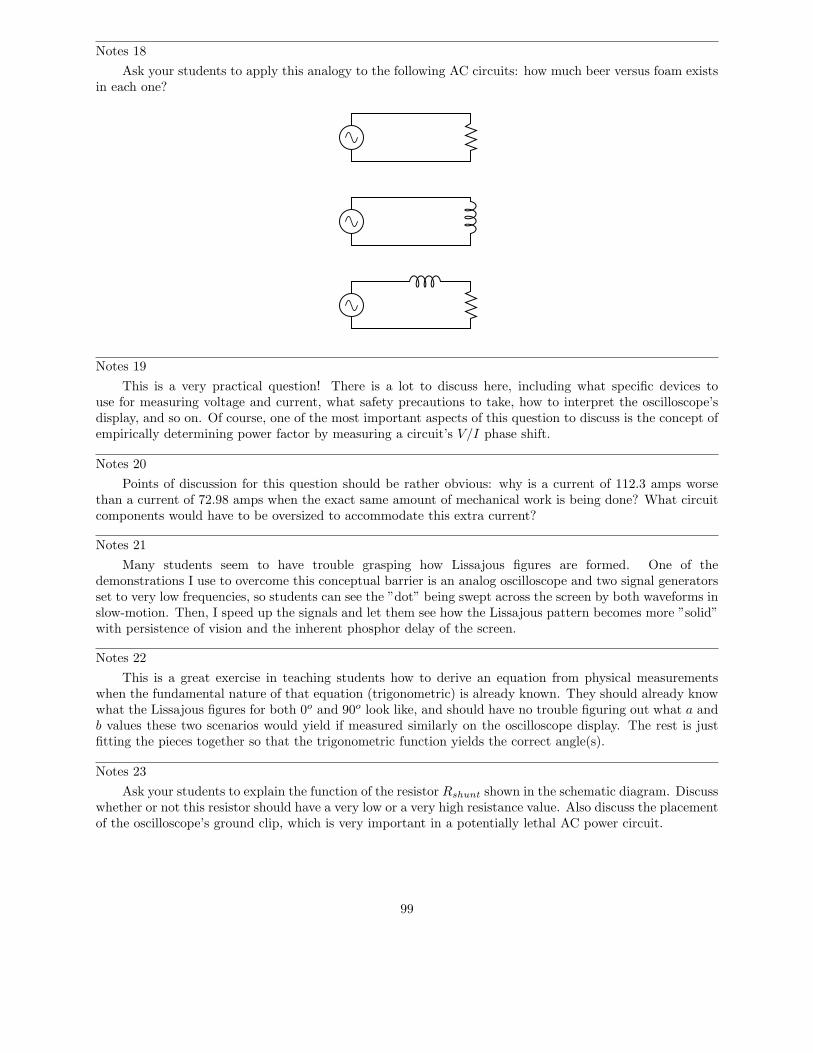
Notes 18
Ask your students to apply this analogy to the following AC circuits: how much beer versus foam existsin each one?
Notes 19
This is a very practical question! There is a lot to discuss here, including what specific devices touse for measuring voltage and current, what safety precautions to take, how to interpret the oscilloscope’sdisplay, and so on. Of course, one of the most important aspects of this question to discuss is the concept ofempirically determining power factor by measuring a circuit’s V/I phase shift.
Notes 20
Points of discussion for this question should be rather obvious: why is a current of 112.3 amps worsethan a current of 72.98 amps when the exact same amount of mechanical work is being done? What circuitcomponents would have to be oversized to accommodate this extra current?
Notes 21
Many students seem to have trouble grasping how Lissajous figures are formed. One of thedemonstrations I use to overcome this conceptual barrier is an analog oscilloscope and two signal generatorsset to very low frequencies, so students can see the ”dot” being swept across the screen by both waveforms inslow-motion. Then, I speed up the signals and let them see how the Lissajous pattern becomes more ”solid”with persistence of vision and the inherent phosphor delay of the screen.
Notes 22
This is a great exercise in teaching students how to derive an equation from physical measurementswhen the fundamental nature of that equation (trigonometric) is already known. They should already knowwhat the Lissajous figures for both 0o and 90o look like, and should have no trouble figuring out what a andb values these two scenarios would yield if measured similarly on the oscilloscope display. The rest is justfitting the pieces together so that the trigonometric function yields the correct angle(s).
Notes 23
Ask your students to explain the function of the resistor Rshunt shown in the schematic diagram. Discusswhether or not this resistor should have a very low or a very high resistance value. Also discuss the placementof the oscilloscope’s ground clip, which is very important in a potentially lethal AC power circuit.
99
Notes 24
This question provides a good opportunity to review the functions of PTs and CTs. Remember thatPTs are transformers with precise step-down ratios used to measure a proportion of the line or phase voltage,which in many cases is safer than measuring the line or phase voltage directly. CTs are specially-formedtransformers which fit around the current-carrying conductor for the purpose of stepping down current(stepping up voltage) so that a low-range ammeter may measure a fraction of the line current.
Students familiar with large electric motors will realize that a 4160 volt motor is going to be three-phaseand not single-phase, and that measuring power factor by means of phase shift between voltage and currentmay be a bit more complicated than what is shown here. This scenario would work for a Y-connectedfour-wire, three-phase system, but not all three-phase systems are the same!
Notes 25
This question provides more practice for students with trigonometry, as well as reinforcing therelationships between S, P , Θ, and power factor.
Notes 26
Although the power factor of this circuit is still 0, the total current drawn from the source has beensubstantially reduced. This is the essence of power factor correction, and the point of this question.
Notes 27
The answers to this question may seem really strange to students accustomed to DC circuit calculations,where parallel branch currents always add up to a greater total. With complex numbers, however, the sumis not necessarily greater than the individual values!
Notes 28
Ask your students to elaborate on the given answer, explaining why power factor results in excessiveline current. Ask them what is meant by the word ”excessive.”
Notes 29
Ask your students to explain what the ”triangle” looks like at a power factor of unity.
Notes 30
This step seems to be one of the most difficult for students to grasp as they begin to learn to correctfor power factor in AC circuits, so I wrote a question specifically focusing on it. Once students calculate theamount of reactive power consumed by the load (Qload), they may realize the capacitor needs to producethe same (QC), but they often become mired in confusion trying to take the next step(s) in determiningcapacitor size.
Notes 31
There are multiple methods of solution for this problem, so be sure to have your students present theirthoughts and strategies during discussion! The formula they write in answer to the challenge question willbe nothing more than a formalized version of the solution strategy.
Notes 32
There are multiple methods of solution for this problem, so be sure to have your students present theirthoughts and strategies during discussion!
Notes 33
There are multiple methods of solution for this problem, so be sure to have your students present theirthoughts and strategies during discussion!
100

Notes 34
There are multiple methods of solution for this problem, so be sure to have your students present theirthoughts and strategies during discussion!
Notes 35
Though there are other methods for correcting power factor in AC circuits, the addition of capacitorsis perhaps the simplest. Ideally, correction capacitors should be added as close to the load terminals aspossible, but in real life they are sometimes located at the power plant (near the alternators). Compare thereduction in conductor currents with the correction capacitor located in different parts of the circuit, andyou will see one place in the system where current is reduced no matter where the capacitor is located!
Still, this does not answer the question of why correction capacitors are not always located at the loadterminals. Discuss this with your students and see if you can figure out why (hint: what happens when theload’s effective resistance changes, as would happen to an electric motor under varying mechanical loads?).
Notes 36
Students generally do not like to explain procedures. They would much rather follow a procedure givenby an Authority, because it requires less thinking. It is your responsibility as their instructor to enforce therequirement for thinking in the classroom. It serves your students little to provide them with step-by-stepinstructions on how to calculate certain things, because ultimately their success will depend on their abilityto think deeply and critically, and to problem-solve all on their own.
Answering this question in a group discussion setting need not be intimidating. You may choose to havegroups of students answer this question instead of just one or two, or you may even assign this questionspecifically to a group of students so that there is the impetus of shared responsibility and the safety offriendly assistance in finding an answer.
Notes 37
Not only would a series-resonant power circuit be dangerous, but it would also require capacitors ratedfor handling large continuous currents. The equivalent series resistance (ESR) of the capacitor would haveto be very low in order to not experience problems handling full load current for extended periods of time.
It should be mentioned that series capacitors sometimes are used in power systems, most notably at theconnection points of some high-voltage distribution lines, at the substation(s).
Notes 38
If some students fail to understand the answer to this question, try drawing an ”upside-down” powertriangle to illustrate:
P
QS
θ
Power triangle for capacitive circuit
101

Notes 39
Ask your students this question: if customers on an electrical system ”consume” reactive power, thenwho has the job of supplying it? Carrying this question a bit further, are the alternators used to generatepower rated in watts or in volt-amps? Is it possible for an alternator to supply an infinite amount of purelyreactive power, or is there some kind of limit inherent to the device? To phrase the question another way,does the necessity of ”supplying” reactive power to customers limit the amount of true power than a powerplant may output?
Notes 40
There is a fair amount of information available on the internet and also in power engineering texts onthe subject of synchronous condensers, although this mature technology is being superseded by solid-statestatic VAR compensator circuits which have no moving parts.
You might wish to mention that most AC generators (alternators) have the ability to run as synchronousmotors, and therefore as synchronous condensers. It is commonplace for spare generators at power plantsto be ”idled” as electric motors and used to generate leading VARs to reduce heating in the windings of theother generators. This is especially true at hydroelectric dams, where frequent shut-downs and start-ups ofgenerator units is discouraged due to the massive size of the units and the physical wear incurred duringthat cycling.
Notes 41
This is another one of those concepts that is better learned through experimentation than by directpronouncement, especially since the experiment itself is so easy to set up.
Notes 42
This question challenges students to relate the magnetic flux waveform (φ) to an instantaneous rotorposition. The answer may come as a surprise to some, who expected maximum induced voltage to occurwhen the rotor is in-line with the stator poles. This answer, however, makes the mistake of confusing flux(φ) with rate-of-flux-change over time (dφ
dt). A rotor lined up with the stator poles would result in maximum
flux (φ) through those poles, but not maximum rate-of-flux-change over time (dφdt
).
Notes 43
Ask your students to write the equation for Faraday’s Law on the whiteboard, and then analyze it in aqualitative sense (with variables increasing or decreasing in value) to validate the answers.
The first answer to this question (increase dφdt
) has been left purposefully vague, in order to makestudents think. What, specifically, must be changed in order to increase this rate-of-change over time?Which real-world variables are changeable after the generator has been manufactured, and which are not?
Notes 44
Answering the follow-up question may require a bit of research on the part of your students. Ask themto describe what ”brushes” are and what ”slip rings” are, and then the mechanical wearing aspects of theseparts should become plain.
Notes 45
Students should realize that there is one cycle of AC voltage produced for every revolution of the rotorshaft. From that point, the problem is simply a matter of unit conversions.
Notes 46
This may be especially confusing to some students, until they realize that alternator poles are alwaysmultiples of 2 (the simplest alternator having 2 poles).
102

Notes 47
Some references provide equations in terms of pole pairs instead of individual alternator poles.
Notes 48
Ask your students how this voltage regulation strategy compares with that of DC generators. Ask themto describe the difference between ”commutator bars” and ”slip rings.”
Notes 49
This question is really a prelude to discussing phase rotation in polyphase systems.
Notes 50
This question is a good exercise of students’ knowledge of phase shift, in a very practical context.
Notes 51
This question is a good exercise of students’ knowledge of phase shift, in a very practical context.
Notes 52
Although the rationale for polyphase electrical power may not be apparent from either the question orthe given answer, your students need to be aware of its existence.
Notes 53
Your students will need to know what ”phase” and ”line” represents in both types of polyphaseconfigurations, especially when using formulae that reference quantities by these labels.
Notes 54
Students will quickly discover that√
3 is the ”magic number” for practically all balanced three-phasecircuit calculations!
It should be noted that although the magnitudes of VAB , VBC , and VAC are equal, their phasor anglesare most definitely not. Therefore,
VAB = VBC = VAC Scalar values equal
VAB 6= VBC 6= VAC Phasors unequal
Notes 55
Students will quickly discover that√
3 is the ”magic number” for practically all balanced three-phasecircuit calculations!
It should be noted that although the magnitudes of IA, IB , and IC are equal, their phasor angles aremost definitely not. Therefore,
IA = IB = IC Scalar values equal
IA 6= IB 6= IC Phasors unequal
103

Notes 56
This phenomenon is difficult to demonstrate without a very powerful magnet. However, if you havesuch apparatus available in your lab area, it would make a great piece for demonstration!
One practical way I’ve demonstrated Lenz’s Law is to obtain a rare-earth magnet (very powerful!), setit pole-up on a table, then drop an aluminum coin (such as a Japanese Yen) so it lands on top of the magnet.If the magnet is strong enough and the coin is light enough, the coin will gently come to rest on the magnetrather than hit hard and bounce off.
A more dramatic illustration of Lenz’s Law is to take the same coin and spin it (on edge) on a tablesurface. Then, bring the magnet close to the edge of the spinning coin, and watch the coin promptly cometo a halt, without contact between the coin and magnet.
Another illustration is to set the aluminum coin on a smooth table surface, then quickly move themagnet over the coin, parallel to the table surface. If the magnet is close enough, the coin will be ”dragged”a short distance as the magnet passes over.
In all these demonstrations, it is significant to show to your students that the coin itself is not magnetic.It will not stick to the magnet as an iron or steel coin would, thus any force generated between the coin andmagnet is strictly due to induced currents and not ferromagnetism.
Notes 57
The phenomenon of Lenz’s Law is usually showcased using a metal solid such as a disk or ring, ratherthan a wire coil, but the phenomenon is the same.
Notes 58
Mechanical speedometer assemblies used on many automobiles use this very principle: a magnetassembly is rotated by a cable connected to the vehicle’s driveshaft. This magnet rotates in close proximityto a metal disk, which gets ”dragged” in the same direction that the magnet spins. The disk’s torque actsagainst the resistance of a spring, deflecting a pointer along a scale, indicating the speed of the vehicle. Thefaster the magnet spins, the more torque is felt by the disk.
Notes 59
Ask your students to describe what would happen to the blinking lights if the voltage were increased ordecreased. Would this alter the perceived speed of motion?
Although this question may seem insultingly simple to many, its purpose is to introduce other sequenced-based phenomenon such as polyphase electric motor theory, where the answers to analogous questions arenot so obvious.
Notes 60
The concept of the rotating magnetic field is central to AC motor theory, so it is imperative that studentsgrasp this concept before moving on to more advanced concepts. If you happen to have a string of blinking”Christmas lights” to use as a prop in illustrating a rotating magnetic field, this would be a good thing toshow your students during discussion time.
Notes 61
Here, we see a practical 3-phase induction motor. Be sure to thoroughly discuss what is necessary toincrease or decrease rotor speed, and compare this with what is necessary to increase or decrease speed in aDC motor.
104

Notes 62
It is very important that students realize Lenz’s Law is an induced effect, which only manifests whena changing magnetic field cuts through perpendicular conductors. Ask your students to explain how theword ”induction” applies to Lenz’s Law, and to the induction motor design. Ask them what conditions arenecessary for electromagnetic induction to occur, and how those conditions are met in the normal operationof an induction motor.
The challenge question is really a test of whether or not students have grasped the concept. If theytruly understand how electromagnetic induction takes place in an induction motor, they will realize thatthere will be no induction when the rotor rotates in ”sync” with the rotating magnetic field, and they willbe able to relate this loss of induction to rotor torque.
Notes 63
One of the reasons three-phase motors are preferred in industry is the simplicity of rotation reversal.However, this is also a problem because when you connect a three-phase motor to its power source duringmaintenance or installation procedures, you often do not know which way it will rotate until you turn thepower on!
Discuss with your students how an electrician might go about his or her job when installing a three-phasemotor. What would be the proper lock-out/tag-out sequence, and steps to take when connecting a motor toits power source? What would have to be done if it is found the motor rotates in the wrong direction?
Notes 64
This is a ”trick” question, in that the student is asked to determine which direction the rotor will startto spin, when in fact it has no ”preferred” direction of rotation. An excellent means of demonstrating thiseffect is to take a regular single-phase motor and disconnect its start switch so that it is electrically identicalto the motor shown in the question, then connect it to an AC power source. It will not spin until you givethe shaft a twist with your hand. But be careful: once it starts to turn, it ramps up to full speed quickly!
The real purpose of this question is to get students to recognize the main ”handicap” of a single-phase ACmotor, and to understand what is required to overcome that limitation. The challenge question essentiallyasks students what happens to a three-phase motor that is suddenly forced to operate as a single-phasemotor due to a line failure. Incidentally, this is called single-phasing of the motor, and it is not good!
Notes 65
Be sure to ask your students to describe how they arrived at the answers to this question. There is morethan one place to start in determining the solution here, and more than one way to calculate some of thefigures. No matter how your students may have approached this question, though, they should all obtainthe same answers.
Notes 66
Be sure to ask your students to describe how they arrived at the answers to this question. There is morethan one place to start in determining the solution here, and more than one way to calculate some of thefigures. No matter how your students may have approached this question, though, they should all obtainthe same answers.
Notes 67
Be sure to ask your students to describe how they arrived at the answers to this question. There is morethan one place to start in determining the solution here, and more than one way to calculate some of thefigures. No matter how your students may have approached this question, though, they should all obtainthe same answers.
105

Notes 68
Be sure to ask your students to describe how they arrived at the answers to this question. There is morethan one place to start in determining the solution here, and more than one way to calculate some of thefigures. No matter how your students may have approached this question, though, they should all obtainthe same answers.
Notes 69
Now, students will surely be able to find a power equation from textbooks, but the purpose of thisquestion is to have them derive it themselves. In a single-phase, resistive AC circuit, power is given by theequation P = IE, just as in DC circuits. However, if you multiply the line voltage by line current, you do notget the correct answer of 27.648 kW. So, obviously, the equation of P = IE will require some modificationfor calculating total three-phase power. However, this modification is not complicated to perform.
Notes 70
This question is good for provoking discussion on the practical, cost-saving benefits of three-phase powersystems over single-phase. Your students will have to do some ”review” research on wire gauges and weights,but the exercise is well worth it.
Notes 71
Use a sine-wave function generator for the AC voltage source. I recommend against using line-powerAC because of strong harmonic frequencies which may be present (due to nonlinear loads operating on thesame power circuit). Specify standard resistor and capacitor values.
I recommend using components that produce a phase shift of approximately 45 degrees within the lowaudio frequency range (less than 1 kHz). This allows most multimeters to be used for voltage measurementin conjunction with the oscilloscope.
Something to suggest that students do is use their oscilloscopes’ ground position on the coupling switch,to help center the dot on the screen before they set up their Lissajous figures for phase shift measurement.
One way for students to do this assessment is to have them predict what the Lissajous figure will looklike, based on circuit component values. They sketch the predicted Lissajous figure on the grid provided(working the math “backward” to arrive at n and m values before actually hooking up an oscilloscope), thenthe instructor assesses them based on the conformity of the real oscilloscope display to their prediction.
General concepts and principles to emphasize
• Basic oscilloscope operation (vertical sensitivity, coupling, timebase, triggering)• Location of “ground” connections on both the oscilloscope and signal generator
Suggestions for Socratic discussion and experimentation
• Based on the position of the oscilloscope’s ground clip, identify the voltage being sensed by each of thetwo input channels. Remember that voltage is always measured between two points!
• Explain what you must do to the oscilloscope in order that the Lissajous figure has the same overallheight and width (i.e. that the two n dimensions are identical), since the two channels clearly do notread the same amount of voltage.
• Identify some way that the oscilloscope could be connected to the circuit to achieve a 90o phase shiftbetween the two channels. Note that this may require some creativity to work around the problem ofground connections between the signal generator and the oscilloscope!
106
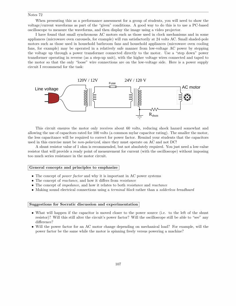
Notes 72
When presenting this as a performance assessment for a group of students, you will need to show thevoltage/current waveforms as part of the “given” conditions. A good way to do this is to use a PC-basedoscilloscope to measure the waveforms, and then display the image using a video projector.
I have found that small synchronous AC motors such as those used in clock mechanisms and in someappliances (microwave oven carousels, for example) will run satisfactorily at 24 volts AC. Small shaded-polemotors such as those used in household bathroom fans and household appliances (microwave oven coolingfans, for example) may be operated in a relatively safe manner from low-voltage AC power by steppingthe voltage up through a power transformer connected directly to the motor. Use a “step down” powertransformer operating in reverse (as a step-up unit), with the higher voltage wires connected and taped tothe motor so that the only “loose” wire connections are on the low-voltage side. Here is a power supplycircuit I recommend for the task:
Line voltage AC motor
Rshunt
24V / 120 VFuse
120V / 12V
This circuit ensures the motor only receives about 60 volts, reducing shock hazard somewhat andallowing the use of capacitors rated for 100 volts (a common mylar capacitor rating). The smaller the motor,the less capacitance will be required to correct for power factor. Remind your students that the capacitorsused in this exercise must be non-polarized, since they must operate on AC and not DC!
A shunt resistor value of 1 ohm is recommended, but not absolutely required. You just need a low-valueresistor that will provide a ready point of measurement for current (with the oscilloscope) without imposingtoo much series resistance in the motor circuit.
General concepts and principles to emphasize
• The concept of power factor and why it is important in AC power systems• The concept of reactance, and how it differs from resistance• The concept of impedance, and how it relates to both resistance and reactance• Making sound electrical connections using a terminal block rather than a solderless breadboard
Suggestions for Socratic discussion and experimentation
• What will happen if the capacitor is moved closer to the power source (i.e. to the left of the shuntresistor)? Will this still alter the circuit’s power factor? Will the oscilloscope still be able to “see” anydifference?
• Will the power factor for an AC motor change depending on mechanical load? For example, will thepower factor be the same while the motor is spinning freely versus powering a machine?
107

Notes 73
The purpose of this assessment rubric is to act as a sort of “contract” between you (the instructor) andyour student. This way, the expectations are all clearly known in advance, which goes a long way towarddisarming problems later when it is time to grade.
Notes 74
Ask your students to observe the waveform shown in the answer closely, and determine what signthe power values always are. Note how the voltage and current waveforms alternate between positive andnegative, but power does not. Of what significance is this to us? What does this indicate about the natureof a load with an impedance phase angle of 0o?
Notes 75
Ask your students to observe the waveform shown in the answer closely, and determine what sign thepower values are. Note how the power waveform alternates between positive and negative values, just as thevoltage and current waveforms do. Ask your students to explain what negative power could possibly mean.
Of what significance is this to us? What does this indicate about the nature of a load with an impedancephase angle of 90o?
The phrase, ”ELI the ICE man” has been used be generations of technicians to remember the phaserelationships between voltage and current for inductors and capacitors, respectively. One area of trouble I’venoted with students, though, is being able to interpret which waveform is leading and which one is lagging,from a time-domain plot such as this.
Notes 76
Ask your students to observe the waveform shown in the answer closely, and determine what sign thepower values are. Note how the power waveform alternates between positive and negative values, just as thevoltage and current waveforms do. Ask your students to explain what negative power could possibly mean.
Of what significance is this to us? What does this indicate about the nature of a load with an impedancephase angle of -90o?
The phrase, ”ELI the ICE man” has been used be generations of technicians to remember the phaserelationships between voltage and current for inductors and capacitors, respectively. One area of trouble I’venoted with students, though, is being able to interpret which waveform is leading and which one is lagging,from a time-domain plot such as this.
Notes 77
In my years of teaching, I have been surprised at how many students struggle with identifying the”leading” and ”lagging” waveforms on a time-domain graph. Be sure to discuss this topic well with yourstudents, identifying methods for correctly distinguishing ”leading” waves from ”lagging” waves.
This question also provides students with good practice expressing leading and lagging waves in phasornotation. One of the characteristics of phasors made evident in the answer is the relative nature of angles.Be sure to point this out to your students.
Notes 78
It may be helpful to your students to remind them of the standard orientation for phase angles in phasordiagrams (0 degrees to the right, 90 degrees up, etc.).
Notes 79
Although semiconductor-based static VAR compensator circuits are now the method of choice formodern power systems, this technique is still valid and is easy enough for beginning students to comprehend.A circuit such as this is a great application of the binary number system, too!
108
Notes 80
This phenomenon is difficult to demonstrate without a very powerful magnet. However, if you havesuch apparatus available in your lab area, it would make a great piece for demonstration!
One practical way I’ve demonstrated Lenz’s Law is to obtain a rare-earth magnet (very powerful!), setit pole-up on a table, then drop an aluminum coin (such as a Japanese Yen) so it lands on top of the magnet.If the magnet is strong enough and the coin is light enough, the coin will gently come to rest on the magnetrather than hit hard and bounce off.
A more dramatic illustration of Lenz’s Law is to take the same coin and spin it (on edge) on a tablesurface. Then, bring the magnet close to the edge of the spinning coin, and watch the coin promptly cometo a halt, without contact between the coin and magnet.
Another illustration is to set the aluminum coin on a smooth table surface, then quickly move themagnet over the coin, parallel to the table surface. If the magnet is close enough, the coin will be ”dragged”a short distance as the magnet passes over.
In all these demonstrations, it is significant to show to your students that the coin itself is not magnetic.It will not stick to the magnet as an iron or steel coin would, thus any force generated between the coin andmagnet is strictly due to induced currents and not ferromagnetism.
Notes 81
An easy way I find to remember Lenz’s Law is to interpret is as opposition to change. The coil willtry to become a magnet that fights the motion. A good way to get students thinking along these lines isto ask them, ”What magnetic polarity would the coil have to assume (in each case) to resist the magnet’srelative motion?” In other words, if the magnet moves closer to the coil, the coil will ”magnetize” so as topush against the magnet. If the magnet moves away from the coil, the coil will ”magnetize” so as to attractthe magnet.
Notes 82
Electromagnetic brakes are very useful devices in industry. One interesting application I’ve seen for thistechnology is the mechanical load for an automotive dynamometer, where a car is driven onto a set of steelrollers, with one roller coupled to a large metal disk (with electromagnets on either side). By varying theamount of current sent to the electromagnets, the degree of mechanical drag may be varied.
Incidentally, this disk becomes very hot when in use, because the automobile’s power output cannotsimply vanish – it must be converted into a different form of energy in the braking mechanism, and heat itis.
Notes 83
A visual aid to understanding the interaction of the two magnetic fields is a diagram showing the linesof flux emanating from the permanent magnets, against the circular lines of flux around the wire. Ask thosestudents who came across similar illustrations in their research to draw a picture of this on the board infront of the class, for those who have not seen it.
Notes 84
Ask your students to explain their answers regarding factors that influence voltage magnitude. Wheredid they obtain their information? Are there any mathematical formulae relating these factors to inducedvoltage?
109
Notes 85
If you happen to have a large, permanent magnet DC motor available in your classroom, you mayeasily demonstrate this principle for your students. Just have them spin the shaft of the motor (generator)with their hands, with the power terminals open versus shorted together. Your students will notice a hugedifference in the ease of turning between these two states.
After your students have had the opportunity to discuss this phenomenon and/or experience itthemselves, ask them why electromechanical meter movement manufacturers usually ship meters with ashorting wire connecting the two meter terminals together. In what way does a PMMC meter movementresemble an electric generator? How does shorting the terminals together help to protect against damagefrom physical vibration during shipping?
Ask your students to describe what factors influence the magnitude of this reaction force.
Notes 86
Note that the two wire ends switch polarity as the loop rotates. Ask your students to explain why thepolarities are as they are.
110

Notes 87
Be sure to note in your discussion with students that the coil does not have to be made of a magneticmaterial, such as iron. Copper or aluminum will work quite nicely because Lenz’s Law is an electromagneticeffect, not a magnetic effect.
The real answer to this question is substantially more complex than the one given. In the examplegiven, I assume that the resistance placed in the coil circuit swamps the coil’s self-inductance. In a casesuch as this, the coil current will be (approximately) in-phase with the induced voltage. Since the inducedvoltage will lag 90 degrees behind the incident (electromagnet) field, this means the coil current will also lag90 degrees behind the incident field, and the force generated between that coil and the AC electromagnetwill alternate between attraction and repulsion:
Time
φelectromagnet
icoil
repel repel repel repel repel repel
attract attract attract attract attract
Note the equal-amplitude attraction and repulsion peaks shown on the graph.
However, in situations where the coil’s self-inductance is significant, the coil current will lag behindthe induced voltage, causing the coil current waveform to fall further out of phase with the electromagnetcurrent waveform:
Time
φelectromagnet
icoil
repel repel repel repel repel
repel
attract attract attract attract attract
Given a phase shift between the two currents greater than 90 degrees (approaching 180 degrees), there isgreater repulsion force for greater duration than there is attractive force. If the coil were a superconducting
111

ring (no resistance whatsoever), the force would only be repulsive!So, the answer to this ”simple” Lenz’s Law question really depends on the coil circuit: whether it is
considered primarily resistive or primarily inductive. Only if the coil’s self-inductance is negligible will thereactive force equally alternate between attraction and repulsion. The more inductive (the less resistive) thecoil circuit becomes, the more net repulsion there will be.
Notes 88
It is easy enough for students to research ”slip speed” in any motor reference book and present adefinition. It is quite another for them to explain why slip is necessary. Be sure to allow ample time in classto discuss this concept, because it is at the heart of induction motor operation.
Notes 89
The concept of ”slip” is confusing to many students, so be prepared to help them understand by wayof multiple explanations, Socratic questioning, and perhaps live demonstrations.
Notes 90
In reality, almost all large synchronous motors are built this way, with an electromagnetic rotor ratherthan a permanent-magnet rotor. This allows the motor to start much easier. Ask your students why theythink this would be an important feature in a large synchronous motor, to be able to start it as an inductionmotor. What would happen if AC power were suddenly applied to a large synchronous motor with its rotoralready magnetized?
If a resistance is connected between the brushes, it allows for an even easier start-up. By ”easier,” Imean a start-up that draws less inrush current, resulting in a gentler ramp up to full speed.
Notes 91
Although it is easy enough for students to find information on squirrel cage motors classifying themas either induction or synchronous, you should challenge your students to explain why it is one type or theother. The goal here, as always, is comprehension over memorization.
Notes 92
There are many details which can be discussed with students regarding these methods of single-phasemotor starting. Thankfully, there are many good-quality sources of information on single-phase motor theoryand construction, so finding information on this topic will not be difficult for your students.
Notes 93
Capacitor-start squirrel-cage induction motors are very popular in applications where there is a need forhigh starting torque. Many induction motor shop tools (drill presses, lathes, radial-arm saws, air compressors)use capacitor-start motors.
Notes 94
It is helpful to review the concept of phase rotation sequences as a string of letters: A-B-C, or C-B-A.Although these two letter sequences are the most common for denoting the two different rotation directions,they are not the only sequences possible using three letters. For example, A-C-B, B-A-C, C-A-B, and B-C-Aare also possibilities. Discuss with your students which of these letter sequences represents the same directionof rotation as A-B-C, and which represent the same direction of rotation as C-B-A. Then, ask your studentshow they might apply these letter sequences to the different wiring diagrams shown in the question.
Notes 95
Consequent pole motors are not the only design with multiple speeds. Sometimes motors are woundwith completely separate, multiple windings, which give them any combinations of speeds desired.
112
Notes 96
This question should provoke some interesting discussion! An interesting ”twist” to this problem isto suggest (after some discussion) that the motor itself checks out fine when tested with an ohmmeter (noground faults, no open or shorted windings), and that its shaft may be turned freely by hand. What couldpossibly be the source of trouble now?
Notes 97
This is a practical scenario which you and your students should have some fun exploring. If they havenever heard of a ”contactor” before, this question is a good opportunity to introduce the component. Bringone with you to discussion if you have the opportunity!
Notes 98
While measuring millivoltage across a fuse may seem like a strange diagnostic technique, it is one I havegainfully applied for years. The ”catch” is you have to know what it is good for and what it is not. It is nota precise, quantitative technique by any means!
Notes 99
An illustration of polyphase alternator construction would be excellent to aid understanding of thisconcept. Your students should have no trouble finding illustrations of three-phase alternator design fromtextbooks and from the internet.
Notes 100
Ask your students how the phase rotation sequence of a three-phase system is typically denoted. Whatsymbols are used to describe the direction in which the phase voltages ”rotate”?
Notes 101
Many students are confused by this when seeing it for the first time. How is it possible to measurevoltage between two points in a circuit and obtain 208 volts, when the two series-connected voltage sourcesbetween those two points are 120 volts each? Why isn’t it 240/120 volts instead?
The answer to this question, of course, is phase shift: the answer to most ”strange” phenomenon in ACcircuits!
Notes 102
The subject of this question is closely related to the subject of ”single-phasing” a polyphase load as theresult of a line conductor opening. In this case it is the neutral conductor we are intentionally opening, butthe results are similar.
Notes 103
Despite the fact that this connection scheme is quite common in industry, I have found little reference toit in textbooks. The equilateral layout of the windings in this diagram facilitates graphical (phasor) analysisof the voltages, providing students with the opportunity to exercise their knowledge of trigonometry.
Notes 104
Ask your students which type of three-phase system (balanced or unbalanced) is easier to analyze, andwhy that is so.
Notes 105
More important than obtaining the correct answer is for students to explain what they did to get thatanswer. What general calculation may be applied to balanced, Y-connected systems relating phase and linevoltages?
113
Notes 106
There exist long, complicated equations for converting between Y and Delta resistor networks, but thereis a much simpler solution to this problem than that! Challenge your students to solve this problem withoutresorting to the use of one of those long conversion formulae.
Notes 107
Ask your students what these results indicate about the reliability of Y versus Delta sourceconfigurations. Also, be sure to ask what does change in the Delta-Y system as a result of the failure.Certainly, something must be different from before, with one winding completely failed open!
Notes 108
Three-phase power transformers are somewhat rare compared to combinations of multiple single-phasetransformers. Questions such as this are really nothing more than pattern-recognition exercises, but like allskills this does not come naturally to all people, and practice improves it!
Notes 109
Being that pole-mounted power distribution transformers are exposed for anyone to look at, theyprovide an excellent opportunity for students to practice identifying three-phase connections. If there areany such transformer configurations located near your campus, it would be an interesting field exercise tobring students there (or send them there on ”field research”!) to identify the connections. Photographs oftransformer connections may also be used in the classroom to provide practical examples of this concept.
Notes 110
Being that pole-mounted power distribution transformers are exposed for anyone to look at, theyprovide an excellent opportunity for students to practice identifying three-phase connections. If there areany such transformer configurations located near your campus, it would be an interesting field exercise tobring students there (or send them there on ”field research”!) to identify the connections. Photographs oftransformer connections may also be used in the classroom to provide practical examples of this concept.
Notes 111
Understanding the open-Delta configuration is made easier if students first understand the robustness ofthe regular Delta configuration: how it continues to provide true three-phase power with no degradation inline voltage in the event of a winding failure. Discuss the advantages and disadvantages of such a configurationwith your students.
Notes 112
The formula for calculating power in a balanced three-phase system may be found in any textbook. Letyour students do the necessary research!
114

Notes 113
These figures came from a real hydroelectric generator that I saw once on a tour. Needless to say, thisalternator was very large!
• Maximum continuous ratings• 615.38 MVA apparent power output• 600 MW true power output• 15 kV line voltage• 23.686 kA line current• 97.5% power factor• 365 volts exciter voltage• 3,425 amps exciter current
• Maximum continuous overload ratings• 707.69 MVA apparent power output• 690 MW true power output• 15 kV line voltage• 27.239 kA line current• 97.5% power factor• 410 volts exciter voltage• 3,640 amps exciter current
Notes 114
Several conversions are necessary to calculate the answer for this question. As usual, the purpose of thisquestion is not so much to obtain an answer, as it is to develop students’ problem-solving skills. How didstudents approach this problem? Did any of them think of ways to simplify the problem so that it could besolved in incremental steps instead of all at once? If so, what was their method(s) of solution?
115