topmaker: a technique for automatic multi-block … · david l. rigby qss group, inc., cleveland,...
TRANSCRIPT

David L. RigbyQSS Group, Inc., Cleveland, Ohio
TopMaker: A Technique for AutomaticMulti-Block Topology Generation Usingthe Medial Axis
NASA/CR—2004-213044
April 2004
FEDSM2003–45527
https://ntrs.nasa.gov/search.jsp?R=20040073477 2018-08-05T05:33:56+00:00Z

The NASA STI Program Office . . . in Profile
Since its founding, NASA has been dedicated tothe advancement of aeronautics and spacescience. The NASA Scientific and TechnicalInformation (STI) Program Office plays a key partin helping NASA maintain this important role.
The NASA STI Program Office is operated byLangley Research Center, the Lead Center forNASA’s scientific and technical information. TheNASA STI Program Office provides access to theNASA STI Database, the largest collection ofaeronautical and space science STI in the world.The Program Office is also NASA’s institutionalmechanism for disseminating the results of itsresearch and development activities. These resultsare published by NASA in the NASA STI ReportSeries, which includes the following report types:
• TECHNICAL PUBLICATION. Reports ofcompleted research or a major significantphase of research that present the results ofNASA programs and include extensive dataor theoretical analysis. Includes compilationsof significant scientific and technical data andinformation deemed to be of continuingreference value. NASA’s counterpart of peer-reviewed formal professional papers buthas less stringent limitations on manuscriptlength and extent of graphic presentations.
• TECHNICAL MEMORANDUM. Scientificand technical findings that are preliminary orof specialized interest, e.g., quick releasereports, working papers, and bibliographiesthat contain minimal annotation. Does notcontain extensive analysis.
• CONTRACTOR REPORT. Scientific andtechnical findings by NASA-sponsoredcontractors and grantees.
• CONFERENCE PUBLICATION. Collectedpapers from scientific and technicalconferences, symposia, seminars, or othermeetings sponsored or cosponsored byNASA.
• SPECIAL PUBLICATION. Scientific,technical, or historical information fromNASA programs, projects, and missions,often concerned with subjects havingsubstantial public interest.
• TECHNICAL TRANSLATION. English-language translations of foreign scientificand technical material pertinent to NASA’smission.
Specialized services that complement the STIProgram Office’s diverse offerings includecreating custom thesauri, building customizeddatabases, organizing and publishing researchresults . . . even providing videos.
For more information about the NASA STIProgram Office, see the following:
• Access the NASA STI Program Home Pageat http://www.sti.nasa.gov
• E-mail your question via the Internet [email protected]
• Fax your question to the NASA AccessHelp Desk at 301–621–0134
• Telephone the NASA Access Help Desk at301–621–0390
• Write to: NASA Access Help Desk NASA Center for AeroSpace Information 7121 Standard Drive Hanover, MD 21076
David L. RigbyQSS Group, Inc., Cleveland, Ohio
TopMaker: A Technique for AutomaticMulti-Block Topology Generation Usingthe Medial Axis
NASA/CR—2004-213044
April 2004
National Aeronautics andSpace Administration
Glenn Research Center
Prepared under Contract NAS3–00145
Prepared for theFourth Joint Fluids Engineering Conferencecosponsored by the American Society of Mechanical Engineersand the Japan Society of Mechanical EngineersHonolulu, Hawaii, July 6–10, 2003
FEDSM2003–45527

Acknowledgments
This research was conducted at the NASA Glenn Research Center under contract with QSS Group, Inc. The authorwould like to thank Mr. Steven Hippensteele of the Turbine Branch and Dr. Raymond Gaugler, Chief of the Turbine
Branch, for their support and encouragement of this research.
Available from
NASA Center for Aerospace Information7121 Standard DriveHanover, MD 21076
National Technical Information Service5285 Port Royal RoadSpringfield, VA 22100
Available electronically at http://gltrs.grc.nasa.gov

NASA/CR—2004-213044 1
TopMaker: A Technique for Automatic Multi-Block Topology Generation Using the Medial Axis
David Rigby
QSS Group, Inc. Cleveland, Ohio 44135
E-mail: [email protected] ABSTRACT
A two-dimensional multi-block topology generation technique has been developed. Very general configurations are addressable by the technique. A configuration is defined by a collection of non-intersecting closed curves, which will be referred to as loops. More than a single loop implies that holes exist in the domain, which poses no problem. This technique requires only the medial vertices and the touch points that define each vertex. From the information about the medial vertices, the connectivity between medial vertices is generated. The physical shape of the medial edge is not required. By applying a few simple rules to each medial edge, the multi-block topology is generated with no user intervention required. The resulting topologies contain only the level of complexity dictated by the configurations. Grid lines remain attached to the boundary except at sharp concave turns where a change in index family is introduced as would be desired. Keeping grid lines attached to the boundary is especially important in the area of computational fluid dynamics where highly clustered grids are used near no-slip boundaries. This technique is simple and robust and can easily be incorporated into the overall grid generation process.
INTRODUCTION
Grid generation remains a pacing technology in many areas where numerical simulations are required. As solver algorithms become more efficient and computers become more powerful, the percentage of time devoted to grid generation becomes higher. At the same time, more and more complex configurations are attempted further increasing the fraction of time spent on grid generation. Computational fluid dynamics problems are particularly difficult because a fine mesh is required near walls where boundary layers must be resolved. These fine mesh regions must generally remain attached to the walls for a high quality mesh. This requirement adds complexity to the topology required for a given configuration.
A significant portion of the time required for grid generation of a structured multi-block grid is spent on designing the topology. For the present work the topology refers to how all the blocks fit together. The present work demonstrates a method by which the topology for a high quality mesh can be generated automatically given only the boundary definition. The generated topology would then be passed on to a grid generator to produce the final grid. Currently the method is implemented for two-dimensional problems. The extension to three-dimensional cases is being actively pursued.
Previous work in the area of automatic quadrilateral grid generation has focused mainly in the area of finite element
analysis on solids. In addition, the focus has been on generating the actual final mesh. The Paving technique of Blacker and Stephenson [1] is an example of a very effective mesh generation method. For the generation of a structured multi-block topology, however, the Paving technique would generate far more quads than needed. It also appears that the Paving technique would introduce more irregular nodes than would generally be required for an efficient multi-block topology. An irregular node is a point where something other than four quads meet. Irregular nodes are also sometimes referred to as topological singularities or dislocations. Other techniques which generate the full unstructured mesh are discussed by Owen et al. [2] and Sampl [3]. While these methods may be useful for the generation of the full mesh, they would not be very efficient to use for topology generation.
Tam and Armstrong [4] have presented work that separates the automatic mesh generation into two phases. The first phase is automatic subdivision and the second phase is meshing. The automatic subdivision phase uses the medial axis to break the complex configurations into relatively simple regions, which are then broken into quads. The approach of Tam and Armstrong is very powerful and was extended to hexahedral mesh generation by Price and Armstrong [5,6] using Midpoint Subdivision [Li et al., 7] to mesh the resulting volumes. Compared to the present technique, the work of Tam and Armstrong is more complex and requires somewhat arbitrary splitting of the original geometry. Each time the geometry is split, the medial axis is regenerated which is presumably the most time consuming part of the process. Sheffer et al. [8] have presented a subdivision process using the embedded Voronoi graph, which is closely related to the medial axis. Only very simple configurations are shown in Sheffer et al. and the lack of symmetry is somewhat disconcerting.
The TopMaker technique focuses on the medial edges. For each medial edge, blocks are added to the topology based on the medial edge type. A total of only six medial edge types exist, three of which correspond to very specific simple configurations. By defining rules for handling the remaining three medial edge types that occur in general configurations, a high quality topology can be generated automatically.
In the following sections of the paper, a short description of the medial axis will be presented followed by an explanation of the TopMaker topology generation technique. Enhancements to the main technique will then be presented followed by additional examples. An attempt has been made to include fairly complex examples that are still clear enough to see easily. The paper is concluded with a discussion of the results including comments on areas for further work.

NASA/CR—2004-213044 2
Figure 1. Simple geometry showing medial surface.
Table 1. Types of medial vertices Vertex type Notation Description
Normal N Three distinct touch points
Corner C On boundary at concave discontinuity
Dangle D Boundary passes through maximum concave curvature
Schematic
A SHORT DESCRIPTION OF THE MEDIAL AXIS
The medial axis is defined as the collection of points that are equidistant to at least two locations on the boundary [9]. In two-dimensional space, medial vertices occur at locations that are equidistant to at least three locations on the boundary. Additionally, medial vertices occur on the boundary where a concave discontinuity in slope exists, and also in regions where the boundary passes through a maximum in concave curvature. Figure 1 shows a relatively simple configuration. The boundary is shown in black. Each interior medial vertex point is shown a
different color with the three associated touch points indicated by lines from the vertex to each touch point. The medial vertices on the boundary are shown in red. In addition, a dashed red line shows the medial axis.
Three types of medial vertices that need to be defined are summarized in table 1. The first type of medial vertex, referred to as a normal vertex, has at least three distinct touch points that define it. The second type of medial vertex, referred to as a corner vertex, occurs at a concave discontinuity on the boundary. The third type of medial vertex, referred to as a dangle vertex, occurs where the boundary passes through a maximum in convex curvature.
Since each medial edge is made up of two medial vertices, there are six possible types summarized in table 2. The first type of medial edge, referred to as a primary edge, is characterized by endpoints that are both normal medial vertices. The second type of medial edge, referred to as a flare, has one normal vertex and one corner vertex. The third type of medial edge, referred to as a dangle edge, has one normal vertex and one dangle vertex. These first three types are the most common.
The final three types do not occur in general cases, but rather correspond to specific configurations. That is to say any additional complexity in the geometry would eliminate the rare type of edge. Table 2 includes a schematic of the type of configuration that would generate each of the rare medial edge types, the Corner-Corner, the Corner-Dangle and the Dangle-Dangle. The blocking for any of these three rare cases is simply specified and then generated if one of these edge types is encountered.
Another special case would correspond to a perfect circle that would have only a single dangle vertex and no medial edges. For the perfect circle, a specified topology would simply be generated. For instance, four blocks wrapping around one central block is a good choice. Conversely to the circle, a doughnut type shape will have single medial edge with no medial vertices. The doughnut shape would be blocked using a single block which wraps around on itself (i.e. an O-grid).
DESCRIPTION OF THE TOPMAKER TECHNIQUE The TopMaker technique can be described in general as follows. Given the configuration as a collection of loops of data (recall only 2D cases will be discussed in the present work), the medial vertices are generated. Each normal medial vertex in the interior, by definition, will have at least three locations on the geometry that are equidistant from the vertex. These locations, which will be referred to as touch points, are stored in association with the vertex. In addition, if a portion of the medial axis connects the current medial vertex to another medial vertex then the other vertex is recorded as a neighbor of the current vertex. There will also be vertices on the geometry surface where a discontinuity in slope occurs. The information about the medial axis is then interrogated to generate the final topology. The specific technique used to find the medial vertices is not pertinent to the present discussion. It should be emphasized at this point that the physical shape of the medial edges is never needed to deduce the connectivity between medial vertices, nor to produce the topology.
N D
C
C

NASA/CR—2004-213044 3
Figure 2. Simple geometry showing resulting topology.
Table 2. Possible types of medial edges Edge type
Notation Likelihood Schematic
Primary N-N Common
Flare N-C Common
Dangle N-D Common
Corner-Corner
C-C Rare
Corner-Dangle
C-D Rare
Dangle-Dangle
D-D Rare
With the medial vertex information in hand, the boundary
data is not required for the topology generation. Three rules or steps essentially define the TopMaker topology generation procedure as follows:
1. Every flare edge will generate a block face. One diagonal of the face will be the flare segment itself, while the second diagonal will result from connecting the two touch points whose included angle surrounds the flare segment (fig. 2).
2. Each primary edge will generate two block faces, one on each side. Each of these block faces will be composed of the primary segment of interest, the two lines connecting each of the vertices to the touch points, and the boundary segment which lies between the appropriate two touch points (fig. 2).
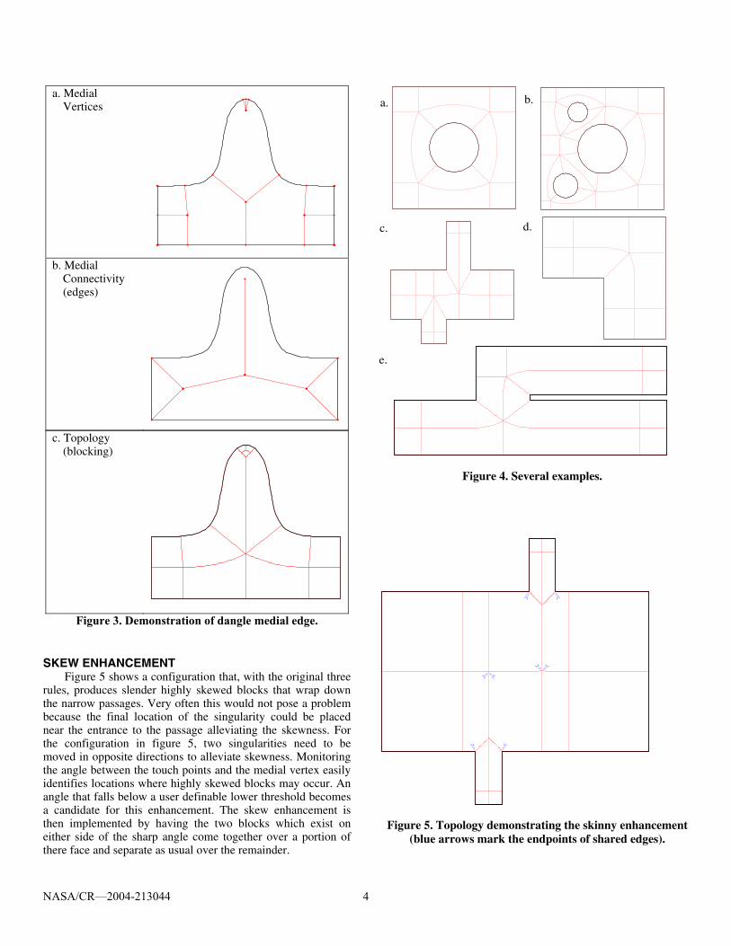
3. The region surrounding a dangle medial edge will generate five blocks (fig. 3). This region is logically U-shaped. This case is handled by generating a wedge shape and then three blocks in a manner appropriate to a triangular region. The wedge shaped region is made up of a portion of the curve on either side of the touch point associated with the dangle vertex, combined with two line segments emanating from the dangle vertex and connecting to the curve. Then an additional block is added to either side of the dangle edge using the appropriate touch points from the normal vertex end and matching the sides at the dangle end with the wedge.
Figures 4a through 4e show the topology which results from the above three rules. In these figures the configuration is shown in thick black lines and the block shapes are drawn in thin red lines. While the block boundaries in these figures are shaped reasonably well for the sake of visual clarity, the actual physical shape of each block is not what is of interest. What the reader should focus on when viewing these examples is the block topology itself. That is to say, how the blocks are arranged and connected to one another. These topologies will result in very high quality grids and they were generated completely automatically. No commercially available software offers this ability, to the author's knowledge. Considering the simplicity of the TopMaker technique, it is hard to imagine that the previous statement will hold true much longer.
The original three rules are sufficient to produce a valid topology. Two additional enhancements are discussed below which can produce improved topologies for many cases.
N-C
N-C
N-D
N-N N-C
NASA/CR—2004-213044 4
a. Medial Vertices
b. Medial Connectivity (edges)
c. Topology (blocking)
Figure 3. Demonstration of dangle medial edge. SKEW ENHANCEMENT
Figure 5 shows a configuration that, with the original three rules, produces slender highly skewed blocks that wrap down the narrow passages. Very often this would not pose a problem because the final location of the singularity could be placed near the entrance to the passage alleviating the skewness. For the configuration in figure 5, two singularities need to be moved in opposite directions to alleviate skewness. Monitoring the angle between the touch points and the medial vertex easily identifies locations where highly skewed blocks may occur. An angle that falls below a user definable lower threshold becomes a candidate for this enhancement. The skew enhancement is then implemented by having the two blocks which exist on either side of the sharp angle come together over a portion of there face and separate as usual over the remainder.
Figure 5. Topology demonstrating the skinny enhancement
(blue arrows mark the endpoints of shared edges).
Figure 4. Several examples.
c.
a. b.
d.
e.

NASA/CR—2004-213044 5
Figure 6. A geometry demonstrating various types of regions.
The user of the technique can choose the exact angle measure where the skew enhancement would occur. As a starting point, it is recommended that the skew enhancement be used when the angle formed by the normal vertex and the two touch points of interest fall below 45. Arrows have been introduced into figure 5 where the skewness enhancement was used. With a kink introduced into the edge of a block, it becomes impossible to visually determine the logical corners of the block. The arrows are introduced on kinked edges to remove any ambiguity as to the location of block corners.
DANGLE ENHANCEMENT
The dangle enhancement basically involves deciding if a dangle medial edge should generate five blocks as usual or only three or even none. In cases where the dangle edge is comparable to the local scale, that is the distance from the dangle vertex to the curve, a modification of rule three is warranted. The two blocks that would match up with the dangle edge itself need not be generated. Instead the entire region occupied by the dangle can be thought of as wedge shaped and filled with three blocks.
Table 3 shows a comparison where the side blocks are retained (normal) and where they are not included (short). In addition, table 3 shows a case where the dangle edge is small
Table 3. Demonstration of dangle enhancement Dangle Type
Parameter Schematic
Normal Le/Ls > 2
Short Le/Ls < 2
Extraneous Le/Ls < 2, and angle<45o
compared to local scale, and the angle between the touch points from the normal medial vertex form a sharp angle (extraneous). In that case, no blocks are generated for the dangle region. The two side blocks are simply brought together resulting a very simple topology.
The user of the technique can choose the exact length ratio and angle measure where these transitions occur. As a starting point, it is recommended that when the length of the dangle edge is less than 2 times the local length scale the two side blocks need not be generated. If, in addition, the angle formed by the normal vertex and the two touch points of interest falls below 45 degrees no blocks will be generated by the dangle vertex.
ADDITIONAL EXAMPLES
Figures 6 through 9 show the blocking for some cases with more complicated geometry. The blocking for each of these cases is no more difficult to produce than for the simpler cases. Each case takes only seconds to calculate; and that includes the generation of the required medial information. While one will notice that the blocks have been drawn with reasonable care, the main point of these examples is to demonstrate what blocks are created and how they are connected. That is to say, the main focus should be on the topology and not on the physical shape of the blocks. Presumably each topology would be passed on to a grid generator where blocks shapes could be modified and the full domain grid would be produced.
The configuration in figure 6 is essentially a randomly drawn shape chosen to test much of the logic involved in the topology generation. One will notice that the grid remains attached to the curve, only allowing a change in index direction at sharp concave corners.
For the hump on the upper left, the dangle edge generated five blocks since the dangle edge is long compared to the local scale at the dangle vertex. On the other hand, the dangle medial edges in the bulb type feature at the upper right only generated three blocks each. For the dangle edges in that region, the edge length and the local scale are comparable.
NASA/CR—2004-213044 6
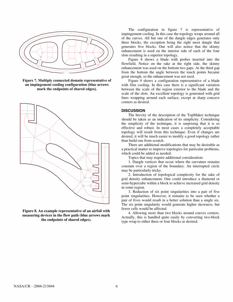
Figure 7. Multiply connected domain representative of an impingement cooling configuration (blue arrows
mark the endpoints of shared edges).
Figure 8. An example representative of an airfoil with measuring devices in the flow path (blue arrows mark
the endpoints of shared edges).
The configuration in figure 7 is representative of impingement cooling. In this case the topology wraps around all of the curves. All but one of the dangle edges generates only three blocks, the exception being the right most dangle that generates five blocks. One will also notice that the skinny enhancement is used on the interior side of each of the four slots resulting in a superior topology.
Figure 8 shows a blade with probes inserted into the flowfield. Notice on the rake at the right side, the skinny enhancement was used on the bottom two gaps. At the third gap from the bottom the angle between the touch points became great enough, so the enhancement was not used.
Figure 9 shows a configuration representative of a blade with film cooling. In this case there is a significant variation between the scale of the region exterior to the blade and the scale of the slots. An excellent topology is generated with grid lines wrapping around each surface, except at sharp concave corners as desired.
DISCUSSION
The brevity of the description of the TopMaker technique should be taken as an indication of its simplicity. Considering the simplicity of the technique, it is surprising that it is so effective and robust. In most cases a completely acceptable topology will result from this technique. Even if changes are desired, it will be much easier to modify a good topology rather than build one from scratch.
There are additional modifications that may be desirable as a practical matter to improve topologies for particular problems, which could be added as needed.
Topics that may require additional consideration: 1. Dangle vertices that occur where the curvature remains
constant over a region of the boundary. An interrupted circle may be particularly tricky.
2. Introduction of topological complexity for the sake of grid density enhancement. One could introduce a diamond or semi-hypercube within a block to achieve increased grid density in some region.
3. Reduction of six point singularities into a pair of five point singularities. However, it remains to be seen whether a pair of fives would result in a better solution than a single six. The six point singularity would generate higher skewness, but fewer cells would be affected.
4. Allowing more than two blocks around convex corners. Actually, this is handled quite easily by converting two-block type wrap to either three or four blocks as desired.

NASA/CR—2004-213044 7
CONCLUSIONS The TopMaker technique, which generates the topology for
a multi-block grid for very general 2D configurations, has been described. As input, the technique requires only the medial vertices with the associated touch points and connectivity information. The physical shape of the medial edge that connects two medial vertices is not required. Three simple rules were described which result in a valid topology. In addition, two enhancements were described which result in improved topologies. This technique should make two-dimensional topology generation truly automatic, which is a significant improvement over the current state of the art. The advantage of the present technique over previous work lies in its simplicity and the fact that a relatively few quads are generated making it ideal for topology generation.
REFERENCES [1] Blacker, T.D. and Stephonson, M.B., "Paving: A New
Approach to Automated Quadrilateral Mesh Generation," Int. J. for Num. Meth. in Eng., Vol. 32, 811–847 (1991).
[2] Owen, S.J., Staten, M.L., Canann, S.A., and Saigal, S., "Advancing Front Quadrilateral Meshing using Triangle Transformations," 7th Int. Meshing Roundtable, (1998).
[3] Sampl, P., "Semi-Structured Mesh Generation Based on the Medial Axis," 9th Int. Meshing Roundtable, (2000).
[4] Tam, T.K.H. and Armstrong, C.G., "2D Finite Element Mesh Generation by Medial Axis Subdivision," Adv. Eng. Software, Vol. 13, 313–324, (1991).
Blade Details
Left Plenum
Right Plenum
Figure 9. Example representative of a cooled turbine blade with cooling slots (blue arrows mark the endpoints of shared edges).

NASA/CR—2004-213044 8
[5] Price, M.A. and Armstrong, C.G., "Hexahedral Mesh Generation by Medial Surface Subdivision: Part I. Solids with Convex Edges," Int. J. for Num. Meth. in Eng., Vol. 38, 3335–3359, (1995)
[6] Price, M.A. and Armstrong, C.G., "Hexahedral Mesh Generation by Medial Surface Subdivision: Part II. Solids with Flat and Concave Edges," Int. J. for Num. Meth. in Eng., Vol. 38, 3335–3359, (1995)
[7] Li, T.S., McKeag, R.M., and Armstrong, C.G., "Hexahedral Meshing using Midpoint Subdivision and Integer Programming," Comput. Methods Appl. Mech. Engrg. Vol. 124, 171–193, (1995).
[8] Sheffer, A., Etzion, M., Rappoport, A., and Bercovier, M., "Hexahedral Mesh Generation using the Embedded Voronoi Graph," 7th Int. Meshing Roundtable, (1998).
[9] Armstrong, C.G., Robinson, D.J., McKeag, R.M., Li, T.S., Bridgett, S.J., Donaghy, R.J., and McGleenan, C.A., "Medials for Meshing and More," 4th Int. Meshing Roundtable, (1995).


This publication is available from the NASA Center for AeroSpace Information, 301–621–0390.
REPORT DOCUMENTATION PAGE
2. REPORT DATE
19. SECURITY CLASSIFICATION OF ABSTRACT
18. SECURITY CLASSIFICATION OF THIS PAGE
Public reporting burden for this collection of information is estimated to average 1 hour per response, including the time for reviewing instructions, searching existing data sources,gathering and maintaining the data needed, and completing and reviewing the collection of information. Send comments regarding this burden estimate or any other aspect of thiscollection of information, including suggestions for reducing this burden, to Washington Headquarters Services, Directorate for Information Operations and Reports, 1215 JeffersonDavis Highway, Suite 1204, Arlington, VA 22202-4302, and to the Office of Management and Budget, Paperwork Reduction Project (0704-0188), Washington, DC 20503.
NSN 7540-01-280-5500 Standard Form 298 (Rev. 2-89)Prescribed by ANSI Std. Z39-18298-102
Form Approved
OMB No. 0704-0188
12b. DISTRIBUTION CODE
8. PERFORMING ORGANIZATION REPORT NUMBER
5. FUNDING NUMBERS
3. REPORT TYPE AND DATES COVERED
4. TITLE AND SUBTITLE
6. AUTHOR(S)
7. PERFORMING ORGANIZATION NAME(S) AND ADDRESS(ES)
11. SUPPLEMENTARY NOTES
12a. DISTRIBUTION/AVAILABILITY STATEMENT
13. ABSTRACT (Maximum 200 words)
14. SUBJECT TERMS
17. SECURITY CLASSIFICATION OF REPORT
16. PRICE CODE
15. NUMBER OF PAGES
20. LIMITATION OF ABSTRACT
Unclassified Unclassified
Final Contractor Report
Unclassified
1. AGENCY USE ONLY (Leave blank)
10. SPONSORING/MONITORING AGENCY REPORT NUMBER
9. SPONSORING/MONITORING AGENCY NAME(S) AND ADDRESS(ES)
National Aeronautics and Space AdministrationWashington, DC 20546–0001
Available electronically at http://gltrs.grc.nasa.gov
April 2004
NASA CR—2004-213044FEDSM2003–45527
E–14481
WBS–22–714–09–11NAS3–00145
14
TopMaker: A Technique for Automatic Multi-Block Topology Generation Usingthe Medial Axis
David L. Rigby
Grid generation; Multiblock grids; Topology; Computational fluid dynamics
Unclassified -UnlimitedSubject Category: 34 Distribution: Nonstandard
QSS Group, Inc.21000 Brookpark RoadCleveland, Ohio 44135
Prepared for the Fourth Joint Fluids Engineering Conference cosponsored by the American Society of MechanicalEngineers and the Japan Society of Mechanical Engineers, Honolulu, Hawaii, July 6–10, 2003. Project Manager,James D. Heidmann, Turbomachinery and Propulsion Systems Division, NASA Glenn Research Center, organizationcode 5820, 216–433–3604.
A two-dimensional multi-block topology generation technique has been developed. Very general configurations areaddressable by the technique. A configuration is defined by a collection of non-intersecting closed curves, which will bereferred to as loops. More than a single loop implies that holes exist in the domain, which poses no problem. This tech-nique requires only the medial vertices and the touch points that define each vertex. From the information about the medialvertices, the connectivity between medial vertices is generated. The physical shape of the medial edge is not required. Byapplying a few simple rules to each medial edge, the multi-block topology is generated with no user intervention required.The resulting topologies contain only the level of complexity dictated by the configurations. Grid lines remain attached tothe boundary except at sharp concave turns where a change in index family is introduced as would be desired. Keepinggrid lines attached to the boundary is especially important in the area of computational fluid dynamics where highlyclustered grids are used near no-slip boundaries. This technique is simple and robust and can easily be incorporated intothe overall grid generation process.

