tops-10 anf-10 networks software installation guide
TRANSCRIPT

TOPS-10 ANF-10 Networks Software Installation Guide AA-W557 A-TB
July 1984
This manual provides information on the assembly, installation, and use of ANF-10 networks software.
This manual supersedes the TOPS-10 Networks Software Installation Guide, AA-5156E-TB and its update AD-5156E-T1 .
OPERATING SYSTEM: TOPS-10 V7.02
Software and manuals should be ordered by title and order number. In the United States. send orders to the nearest distribution center. Outside the United States. orders should be directed to the nearest DIGITAL Field Sales Office or representative.
Northeast/MId-Atlantic Region Central Region Western Region
Digital Equipment Corporation Digital Equipment Corporation Digital Equipment Corporation PO Box CS2008 Accessories and Supplies Center Accessories and Supplies Center Nashua. New Hampshire 03061 1050 East Remington Road 632 Caribbean Drive Telephone:(603)884-6660 Schaumburg. Illinois 60195 Sunnyvale. California 94086
Telephone:(312)64G-5612 Telephone:(408)734-4915
digital equipment c.orporatlon. marlboro massachusetts

First Printing, July 1984
:c Digital Equipment Corporation 1984. All Rights Reserved.
The information in this document is subject to change without notice and should not be construed as a commitment by Digital Equipment Corporation. Digital Equipment Corporation assumes no responsibility for any errors that may appear in this document.
The software described in this document is furnished under a license and may only be used or copied in accordance with the terms of such license.
No responsibility is assumed for the use or reliability of software on equipment that is not supplied by DIGITAL or its affiliated companies.
The following are trademarks of Digital Equipment Corporation:
~D~DDmDrM DEC MASSBUS RSX DECmate PDP RT DECsystem-10 PiOS UNIBUS DECSYSTEM-20 Professional VAX DECUS Q-BUS VMS DECwriter Rainbow VT DIBOL RSTS Work Processor
The postage-prepaid READER'S COMMENTS form on the last page of this Ijocument requests the user's critical evaluation to assist us in preparing future documentation.

PREFACE
CHAPTER 1
1.1 1.1.1 1.1.2 1.1.3 1.1.4 1.2 1.2.1 1.2.2
CHAPTER 2
2.1 2.1.1 2.1.2 2.1.3 2.1.4 2.1.5 2.1.6 2.1.7 2.2
CHAPTER 3
3.1 3.1.1 3.1.2 3.1.3 3.1.4 3.1.5
3.1.6 3.1.6.1 3.2
3.2.1 3.2.2 3.2.3 3.3 3.4
CHAPTER 4
4.1
4.2 4.3 4.4 4.5 4.6 4.6.1
CONTENTS
THE TOPS-10 ANF-10 NETWORK
NETWORK OVERVIEW • . . . . . . . . 1-1 Host Processors • 1-1 Communications Front Ends • • • 1-3 Remote Stations • • • • Network Configurations • • • • • • • • • • •
INSTALLATION OVERVIEW • • • • Network Installation Requirements •••• Installation Summary • • • • •
COPY THE DISTRIBUTED SOFTWARE TO DISK
• • 1-3 • • 1-4
• 1-6 • 1-6 • 1-7
NETWORK SOURCE MODULES •• •• • • • • • • • • 2-1 Required PDP-II Modules •••••• 2-1 PDP-II Device Modules • • • • • • 2-2 PDP-II Debugging Modules • • • 2-3 Miscellaneous PDP-II Modules •••••••• 2-3 DCP Modules •••• • •••••••• 2-3 PDP-8 (DN92) Mod u1 es • • • • • • 2-4 Supplementary Files • • • • • • • • • •• 2-4
COPY PROCEDURE • • • • • • • • • • • ••••• 2-5
CREATE A CONFIGURATION FILE
SELECT YOUR FILE ENTRIES • • • • • • • • Required Entries for All PDP-II Nodes Synchronous Line Entry • • • • • • • • Asynchronous Line and Terminal Entries Global Entries Defining Terminals Global Entries that Change the Network Environment ••• • • • • • • • • •• Entries for PDP-8-based DN92 Nodes ••
DN92 Configuration File Defaults •• CONFIGURATION-DEFINING MACROS FOR PDP-II-BASED NODES •••••••••••
The TDEF Macro • • • • • • • The DHCNFG Macro •••••• The DHUSE Macro • • • •
SAVE THE CONFIGURATION FILE EXAMPLES OF CONFIGURATION FILES
ASSEMBLE THE SOFTWARE
SELECT ASSEMBLY SOURCE MODULES FOR PDP-II-BASED
• • 3-1 3-4
• 3-5 3-5
• • 3-7
3-8 3-10 3-11
3-11 3-12 3-12 3-13 3-14 3-14
PROCESSORS • • • • • • • • • • • • • • • • • • • • 4-1 ASSEMBLE SOFTWARE FOR PDP-II-BASED PROCESSORS • • 4-2 CHECK PROGRAM SIZE FOR PDP-II-BASED PROCESSORS • • 4-3 EXAMPLES FOR PDP-II-BASED PROCESSORS • • • •• 4-4 EXAMPLES OF SAVING SYMBOLS WITH DDTll • • • 4-7 ASSEMBLE SOFTWARE FOR PDP-8-BASED PROCESSORS 4-10
Submitting a DN92 Control File • • • • • • 4-11
iii
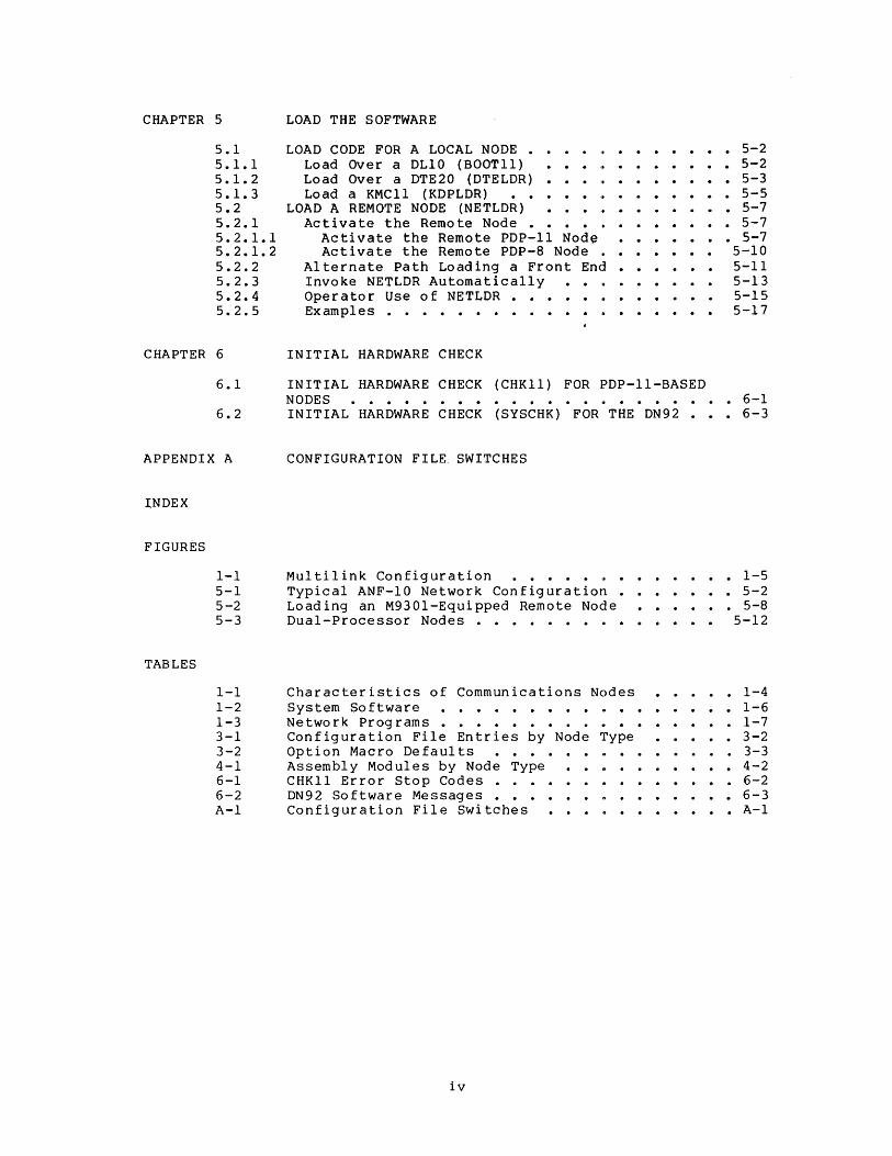
CHAPTER 5 LOAD THE SOFTWARE
5.1 5.1.1 5.1.2 5.1.3 5.2 5.2.1 5.2.1.1 5.2.1.2 5.2.2 5.2.3 5.2.4 5.2.5
LOAD CODE FOR A LOCAL NODE • Load Over a DLI0 (BOOTll) Load Over a DTE20 (DTELDR)
<, • • • • • • • 5-2 • • • j' ••• • • 5-2
• • 5-3 Load a KMCll (KDPLDR) . . . '. . . . . . . . 5-5
LOAD A REMOTE NODE (NETLDR) • • 5-7 '. . . . . . . . 5-7
• • • • • • • 5-7 Activate the Remote Node • •
Activate the Remote PDP-II Node Activate the Remote PDP-8 Node •
Alternate Path Loading a Front End • Invoke NETLDR Automatically Operator Use of NETLDR • Examples • • • • • • • • • •
• • •• 5-10 5-11 5-13 5-15
. . ,. . . . . .. 5-1 7
CHAPTER 6 INITIAL HARDWARE CHECK
6.1 INITIAL HARDWARE CHECK (CHKll) FOR PDP-II-BASED NODES • • • • • • • • • • • • • • •• • 6-1
6.2 INITIAL HARDWARE CHECK (SYSCHK) FOR THE DN92 • • • 6-3
APPENDIX A CONFIGURATION FILE. SWITCHES
1;NDEX
FIGURES
TABLES
1-1 5-1 5-2 5-3
Multilink Configuration •••••••• Typical ANF-I0 Network Configuration • • Loading an M9301-Equipped Remote Node Dual-Processor Nodes • • • • • • • ~ • •
• 1-5 . . . . . 5-2
• 5-8 5-12
1-1 Characteristics of Communications Nodes • 1-4 1-2 System Software ..••••••• n • • • 1-6 1-3 Network Programs • • • • • • • • . • 1-7 3-1 Configuration File Entries by Node Type .•••• 3-2 3-2 Option Macro Defaults ••.•• • •••• 3-3 4-1 Assembly Modules by Node Type •••• 4-2 6-1 CHKll Error Stop Codes . • • • • 6-2 6-2 DN92 Software Messages • • • • • • • • • • • 6-3 A-I Configuration File Switches ••••• A-I
iv

PREFACE
This manual is intended for software installers and system operators responsible for installing the Advanced Network Functions software for the TOPS-IO operating system (TOPS-IO ANF-IO) on communications front ends and remote nodes. It assumes that the reader knows how to
• log in on a TOPS-IO host
• use BACKUP to restore data from tapes to disk
• use an editor such as SOS or TECO
• run MONGEN
In order to install network software, you must have a running TOPS-IO operating system. Use the instructions in the TOPS-IO Software Installation Guide before using this manual. For information on installing TOPS-IO DECnet-lO network software, see the manual entitled DECnet-lO Network Generation and Installation Procedures. For information on installing IBM communications software, see the manual entitled TOPS-IO IBM Emulation/Termination.
Not all the hardware mentioned in this manual is currently supported by TOPS-IO ANF-IO. For current support status of hardware and software, please refer to the TOPS-IO Version 7.02 Software Product Description (SPD).
This publication does not cover the design of a network. It assumes that the network topology has already been decided upon and that the hardware and DIGITAL-supplied software are available.
This installation guide is organized as follows:
• Chapter 1 provides an introduction to TOPS-IO ANF-IO network configurations and an overview of the installation procedures.
• Chapter 2 describes the DIGITAL-supplied software and the procedures for copying it to your system's storage area.
• Chapter 3 describes the generation of a configuration file for each node in the network.
• Chapter 4 describes the assembly of the selection of the source modules used assembly.
v
software and as input to
the the

• Chapter 5 describes the loading procedures communications front ends and the remote nodes.
for the
• Chapter 6 describes the initial hardware check as the node is loaded and started.
• Appendix A contains a comprehensive list of all available configuration switches.
Documents referenced in this manual or useful during the installation and checkout procedures are:
TOPS-IO Software Installation Guide
TOPS-IO Operating System Commands Manual
TOPS-IO Operator's Guide
DECnet-lO Network Generation and Installation Procedures
BOOTll Specification
DTELDR Specification
INITIA Specification
KDPLDR Specification
NETLDR Specification
REACT Specification
TOPS-IO Remote Station Guide
TOPS-IO CHKll Manual
TOPS-IO/TOPS-20 DDTll Manual
TOPS-IO IBM Emulation/Termination
DN92 User's Guide
PDP-II Peripherals Handbooks (1976)
Terminals and Communications Handbook (1979)
Large Systems Product Summary (1980)
vi
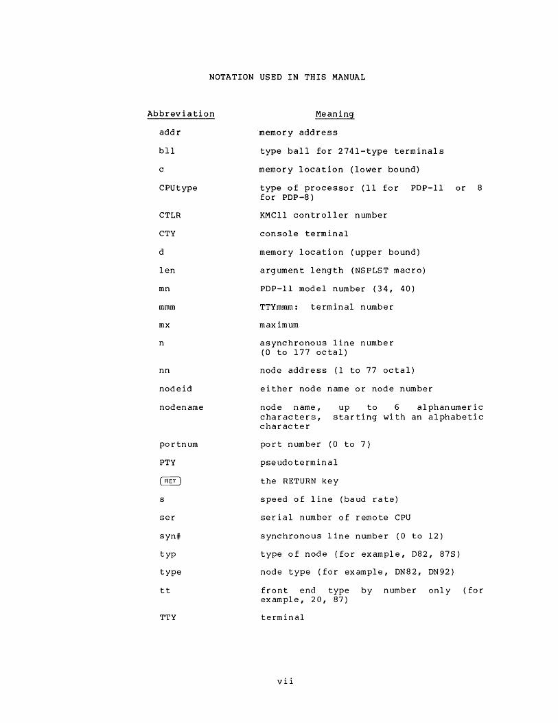
NOTATION USED IN THIS MANUAL
Abbreviation
addr
bll
c
CPUtype
CTLR
CTY
d
len
mn
mmm
mx
n
nn
nodeid
nodename
portnum
PTY
s
ser
syn#
typ
type
tt
TTY
Meaning
'memory address
type ball for 2741-type terminals
memory location (lower bound)
type of processor (11 for PDP-II or 8 for PDP-8)
KMCll controller number
console terminal
memory location (upper bound)
argument length (NSPLST macro)
PDP-II model number (34, 40)
TTYmmm: terminal number
max imum
asynchronous line number (0 to 177 octal)
node address (1 to 77 octal)
either node name or node number
node name, characters, character
up to 6 alphanumeric starting with an alphabetic
port number (0 to 7)
pseudoterminal
the RETURN key
speed of line (baud rate)
serial number of remote CPU
synchronous line number (0 to 12)
type of node (for example, 082, 87S)
node type (for example, DN82, DN92)
front end type by number only (for ex am pI e, 20, 87)
terminal
vii

w
x
xxx
y
#as
#sy
width of line (in columns)
CPU number (DTELDR)
feature identifier RNN,TAB)
DTE number (DTELDR)
(for example,
number of available asynchronous lines (0 to 177 octal; TTYN equals this value)
number of synchronous lines (0 to 12 octal; NLINES equals this value)
viii

CHAPTER 1
THE TOPS-IO ANF-IO NETWORK
This chapter provides an overview of Functions (ANF-lO) network hardware installation procedures.
1.1 NETWORK OVERVIEW
the TOPS-IO Advanced Network and an outline of the software
The TOPS-IO ANF-IO network is a configuration of TOPS-IO central processors (hosts), communications control systems (front ends), and remote stations interconnected over communications lines. The lines, also called links, can be as short as a few feet when connecting a front end to its central processor, or many miles long when connecting remote stations to the central site over telephone lines or radio relay links.
DECnet-lO, a separate product, allows a TOPS-IO system to be part of a DECnet network and to communicate with VAX/VMS, TOPS-20, RSX-ll, RSTS, and RT systems. DECnet-lO also replaces the DECnet Compatible Port (DCP) •
The computer systems that attach to a line are called nodes, whether hosts, front ends, or remote stations. Each node is identified by a unique node number and a unique node name. The node number is a nonzero two-digit octal number, limiting the maximum number of nodes in a TOPS-IO ANF-IO network to 63 (77 octal). The node name must begin with a letter and can contain up to six alphanumeric characters.
1.1.1 Host Processors
When you create a monitor that is to support a TOPS-IO ANF-IO network, you must run MONGEN and answer the network-related questions in its HDWGEN, TTYGEN, NETGEN, and FGEN segments appropriately. Those questions are described below.
1-1

THE TOPS-IO ANF-IO NETWORK
In the HOWGEN segment, respond to the network-re!lated prompts as follows:
Proml2 t Resl20nse
Allow jobs to be locked in core? Y
1t high priority queues (0,0-15) Use a value greater than 0 so that you can set a HPQ switch in NETLDR. IN I.
MSGSER (Y,N) Y to use DTELDR. (You must answer this question with Y if you have nodes connected to DTEs, such as the DN20 or DN87S.)
1t PTYs (20,0-510) Use any value in the allowed range. (The total of PTYs plus TTYs declared in all MaNGEN segments must not exceed 511.)
In the TTYGEN segment of MaNGEN, specify that lines 0-777 are LINES WHICH RUN INITIA AT STARTUP. For lines on your console front end, and lines on any 2020 (KSlO), you must also specify their line speeds (and othe r char ac ter i st ic s) in TTY. IN I.
In the NETGEN segment of MaNGEN, specify that you want network support and give information on the following:
number of local CPUs:
number of DLIO-interfaced nodes on CPUO:
number of DTE20-interfaced nodes on each CPU:
host node number:
host node name:
number of remote TTYs:
whether you have
network virtual terminals:
remote card readers:
remote line printers:
remote data entry terminals:
remote task-to-task:
number of connects:
See the NETGEN dialogue in the TOPS-IO Software Inst.allation Guide for more information.
In the FGEN segment of MaNGEN, specify either KIFULL, KLFULL, or KSFULL to the Feature Set prompt. Only these monitors support TOPS-IO ANF-IO networks.
1-2
THE TOPS-IO ANF-IO NETWORK
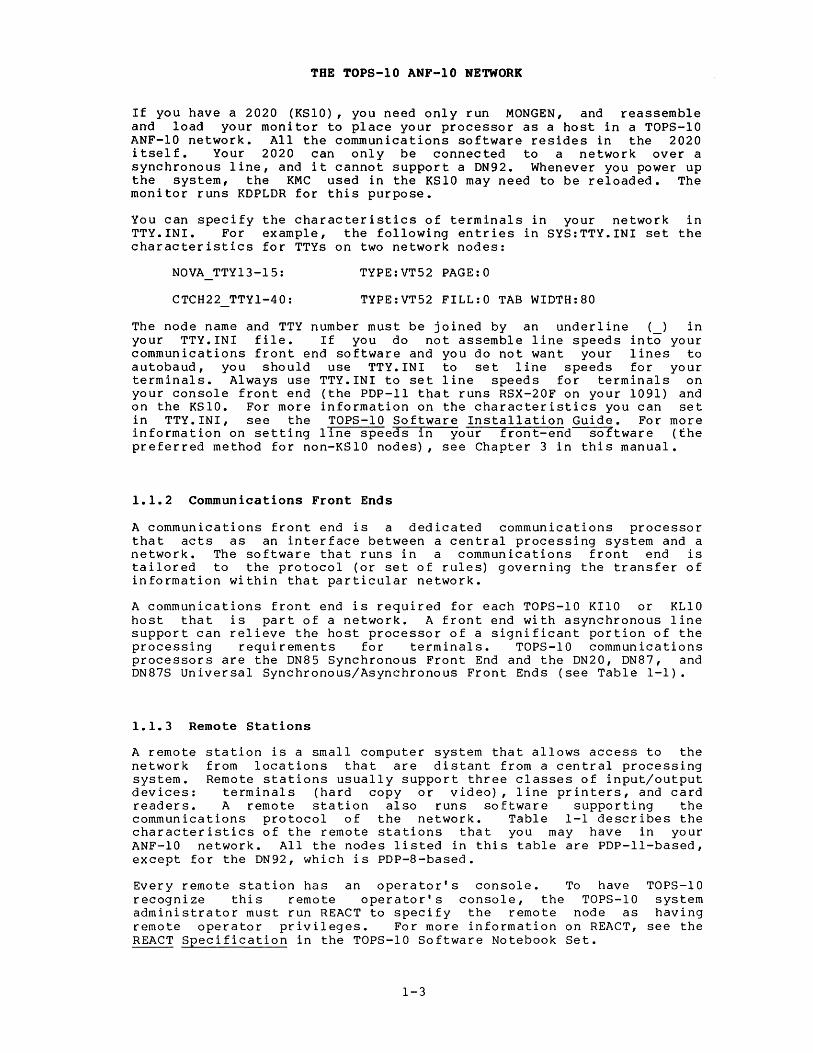
If you have a 2020 (KSlO), you need only run MaNGEN, and reassemble and load your monitor to place your processor as a host in a TOPS-lO ANF-lO network. All the communications software resides in the 2020 itself. Your 2020 can only be connected to a network over a synchronous line, and it cannot support a DN92. Whenever you power up the system, the KMC used in the KSlO may need to be reloaded. The monitor runs KDPLDR for this purpose.
You can specify the characteristics of terminals in your network in TTY.INI. For example, the following entries in SYS:TTY.INI set the characteristics for TTYs on two network nodes:
NOVA TTY13-l5: TYPE:VT52 PAGE:O
CTCH22 TTYl-40: TYPE:VT52 FILL:O TAB WIDTH:80
The node name and TTY number must be joined by an underline () in your TTY.INI file. If you do not assemble line speeds into your communications front end software and you do not want your lines to autobaud, you should use TTY.INI to set line speeds for your terminals. Always use TTY.INI to set line speeds for terminals on your console front end (the PDP-II that runs RSX-20F on your 1091) and on the KSlO. For more information on the characteristics you can set in TTY.INI, see the TOPS-lO Software Installation Guide. For more information on setting line speeds in your front-end--soItware (the preferred method for non-KSlO nodes), see Chapter 3 in this manual.
1.1.2 Communications Front Ends
A communications front end is a dedicated communications processor that acts as an interface between a central processing system and a network. The software that runs in a communications front end is tailored to the protocol (or set of rules) governing the transfer of information within that particular network.
A communications front end is required for each TOPS-IO KIlO or KLIO host that is part of a network. A front end with asynchronous line support can relieve the host processor of a significant portion of the processing requirements for terminals. TOPS-I0 communications processors are the DN85 Synchronous Front End and the DN20, DN87, and DN87S Universal Synchronous/Asynchronous Front Ends (see Table 1-1).
1.1.3 Remote Stations
A remote station is a small computer system that allows access to the network from locations that are distant from a central processing system. Remote stations usually support three classes of input/output devices: terminals (hard copy or video), line printers, and card readers. A remote station also runs software supporting the communications protocol of the network. Table 1-1 describes the characteristics of the remote stations that you may have in your ANF-I0 network. All the nodes listed in this table are PDP-II-based, except for the DN92, which is PDP-8-based.
Every remote station has an operator's console. To have TOPS-I0 recognize this remote operator's console, the TOPS-I0 system administrator must run REACT to specify the remote node as having remote operator privileges. For more information on REACT, see the REACT Specification in the TOPS-IO Software Notebook Set.
1-3

THE TOPS-lO ANF-lO NETWORK
Table 1-1: Characteristics of Communications Nodes
~.
No. of No. of Node Node Synch. Asynch. Card Type Use Lines Lines Printer Reader
DN20 Front End l 0-12 0-128 0 0
DN82 RJE & Conc. 1-4 1-16 1 1
DN87 Front End 0-10 0-96 0 0
DN87S' Front End 0-12 0-128 0 0
DN92 RJE & Conc. 1 1-16 2 1 1
DN200 RJE.& Conc. 1-2 1-32 1 1
2020 Host 1-2 1-32 1 1
The allowable number of lines depends on the mix of high-speed synchronous lines, low-speed synchronous lines, asynchronous lines, and activated feature-test switches.
The DN92 can have one asynchronous lines, or asynchronous lines, or 1 asynchronous lines.
1.1.4 Network Configurations
of the following combinations: 16 1 printer or card reader with 12 printer with 1 card reader and 8
Network configurations (topologies) are generally determined by the
• geographical distribution of the nodes
• volume and scheduling of communications traffic
• cost of lines and hardware
Configurations supported by TOPS-IO ANF-IO include simple network topologies such as point-to-point and star. They also include more complex multi1ink and mu1tipath configurations with features such as multiple hosts and dynamic topologies.
Complex topologies are composed of multiple links and multiple nodes. A mu1tilink configuration can include multiple TOPS-IO hosts in the same network. A multihost configuration permits the user at a terminal of a remote station to select his host with the SET HOST command. The route-through capability allows communication between two nodes that are indirectly connected through one or more intermediate nodes (for example, see nodes FOUR and SEVEN in Figure 1-1) •
1-4

Node ONE
TOPS-10 HOST
Node FIVE
TOPS-10 HOST
THE TOPS-IO ANF-IO NETWORK
Node TWO
DN87S
DN87S --G---
RSX-llM
Figure 1-1: Multilink Configuration
1-5
DN80 RJE
DN81 CONC.
DN82 RJE
CONC.
remote TTYs
remote TTYs
MR-S-823-80

THE TOPS-IO ANF-IO NETWORK
1.2 INSTALLATION OVERVIEW
This manual describes the generation and installation of ANF-IO network software. You must have a fully operational TOPS-IO monitor and be familiar with its use to perform the procedures contained in the following chapters. You may need to create or update a new TOPS-IO monitor to support TOPS-IO ANF-IO network software. To create or update a TOPS-IO operating system, please refer to the TOPS-IO Software Installation Guide before following the instructions in this manual.
1.2.1 Network Installation Requirements
To perform the appropriate network generation and installation procedures, you should have access to the system programs listed in Table 1-2 that apply to your system.
Table 1-2: System Software
Program Name
BACKUP
BOOTll
CREF
DDTII
DTELDR
KDPLDR
MACDLX
NET LOR
PALlO
Used to Install
all nodes
DN87
DN92
all nodes except 2020
DN20, DN87S
2020
DN20,DN80-series, DN200
Remote nodes
DN92
1-6
Function
Copies network software from the distribution tape to the system disk.
Loads network software into a communications front end over a DLIO.
Prepares a cross-reference listing, following assembly of software.
Allows you to examine and deposit code and data in a running PDP-8 or PDP-II node. You can also use it to read memory dumps from these machines.
Loads network software into a communications front end over a DTE20.
Loads microcode into KMC.
the
Assembles PDP-II software on a TOPS-IO host.
Loads software downline into a remote node over a synchronous line.
Assembles PDP-8 software on the TOPS-IO host.

THE TOPS-10 ANF-10 NETWORK
Network programs listed in Table 1-3 are found on the second saveset of the Distribution Tape or on the customer-supported tape.
Table 1-3: Network Programs
Program Used to Name Install Function
source all nodes except 2020 Used to assemble network code software for each network
node. Source files for DN20, DN200, and DN80-ser ies nodes are * .Pll files; for DN92 nodes, DN92. PAL files. See Section 2.1 for descriptions of these source modules.
TSKSER all host nodes Provides task-to-task capabilities, such as file-transfer facilities (with PIP) between nodes in the network.
1.2.2 Installation Summary
The network software installation procedure contains six operations:
1. Copy the files from the CUSP tape to your disk area. Do this first so that the updated CUSP files on the main monitor Distribution Tape will supersede the CUSP tape files when you perform step 2.
2. Copy the network software files from the Distribution Tape to yo u r dis k are a •
3. For each node, create a configuration file that reflects the environment in which the node will operate.
4. Assemble the network software for each node.
5. Load each node with its assembled software. The load procedures vary according to whether the node is remote (for example, a remote station) or local (for example, a communications front end). If the node is local, loading procedures vary according to the type of interface to the TOPS-IO host.
6. Examine your initial system output. This is either CHKll output (if the node you load is a PDP-II) or SYSCHK output (if the node is a PDP-8). This hardware check program runs whenever a node is loaded and started (but not when it is restarted manually). The space occupied by the check program is reclaimed and used as buffer space when the node is running.
During the software installation of a remote node and subsequently when the node is running, you may need to examine the node software. DDTll is a remote debugging program that allows you to examine a running node. For information on DDTll, see the TOPS-IO/TOPS-20 DDTll Manual.
1-7


CHAPTER 2
COPY THE DISTRIBUTED SOFTWARE TO DISK
The procedures in this chapter enable you to copy the DIGITAL-supplied network software from the Distribution Tape to your disk. The network software is used in subsequent chapters to generate customized code for each netwQrk node.
2.1 NETWORK SOURCE MODULES
When you are ready to assemble the software for each node, you must supply the MACDLX or PALlO assembler with a list of source modules, a listing file name, a binary file name, and switches.
2.1.1 Required PDP-ll Modules
The following modules apply to all PDP-II-based nodes and include all modules in each assembly. The modules are described in the order in which they must appear when you do your assembly.
filename.Pll
S.Pll
MACROS.Pll
DNCNFG.Pll
DNCOMM.Pll
DNNCL.Pll
DNDCMP. Pll
is the node configuration file you the instructions in Chapter 3. C.Pll or representative of the CN8222.Pll). This file must specified at assembly time.
create according to The filename may be
node (for example, be the first file
contains the symbol definitions used by the network software. ThJ.s file must be the second file specified at assembly time.
contains system macro definitions used by the network software. This file must be the third file specified at assembly time.
processes the configuration parameters and feature test switches that you entered in the filename.Pll file. This file must be the fourth file specified at assembly time.
contains common data and code such as the main loop and clock routines.
contains the Network Control Language (NCL) routines.
contains the Digital Data Protocol (DDCMP) code.
2-1
Communications Message

DNLBLK. Pll
CHKll.Pll
COPY THE DISTRIBUTED SOFTWARE TO DISK
contains line block definitions interface. This file must be
and the
the CHKll next-to-last
specified at assembly time.
contains the code that performs the initial check of each device present on the node. must be the last specified at assembly time.
hardware This file
2.1.2 PDP-II Device Modules
The following modules are device drivers; their inclusion in the assembly file list depends on each node's configuration. For more information on the hardware components, see either the PDP-II Peripherals Handbook (1976) or the Terminals and Communications Handbook (1979). In the list below, entries in brackets [] indicate the unit as described in the Large Systems Product Summary (1980).
DNDLlO.Pll
DNDTE.Pll
DNCDDQ.Pll
DNCDMC.Pll
DNCDDH.Pll
DNCDUP.Pll
DNDMll.Pll
DNDHll.Pll
DNDZll.Pll
DNLPT. Pll
DNCRD.Pll
DNDN 11. Pll
contains driver code for the DLIO interface [DN87].
contains driver [DN87S,DN20] •
code for the DTE20 interface
contains synchronous line driver code for the DQll communications interface on the DN80-series [DN8x-H or -J] •
contains synchronous line driver code communications interface on the [DN21-BA, -BB, -HA and DNSXX-AA, -AB].
for DN20
the and
DMCII DN200
contains line driver code for the DHII 16-line asynchronous serial line multiplexer. Use this module with point-to-point or multidrop configurations, and be sure to use DNDHll.Pll with it. Use this module when the asynchronous line uses DDCMP to communicate with RDX-type devices or other nodes [DN8x-EA to -ED; used wit h DM 11 s] •
contains synchronous line driver code for the DUPII communications interface on the DN20 [DN20-BA or -BB].
contains the DMII modem control routines [DN8x-EA to -ED; used with DHlls].
contains the DHll asynchronous line interface code. Use this module when communicating with TTYs [DN8x-EA to -ED]. This module can be used alone without other device drivers.
contains the DZII asynchronous line interface code, the DZll modem control routines, and the line driver code for the DZll 8-line asynchronous serial line multiplexer [DN25-AA, -AB, or -BA]
contains the code for the line printer routines; used with the LPII interface.
contains the code for the card reader routines; used with the CRII interface.
contains the code to support the DNll automatic dialing interface device.
2-2

COPY THE DISTRIBUTED SOFJwARE TO DISK
2.1.3 PDP-II Debugging Modules
The following modules are useful when examining dumps of nodes, or when testing running nodes.
DNTRCE.Pll
DNDBG. Pll
contains the code to support the optional tracing facility. This is a debugging tool.
contains the debugging storage blocks.
2.1.4 Miscellaneous PDP-II Modules
The following modules perform other network functions. Their inclusion in the assembly file list depends on the node configuration and any special operating environment that may be required.
DNDEV.Pll
DNTTY.Pll
DN2741.Pll
DNCTAB.Pll
DNRDA.Pll
DNRDE.Pll
DNTSK.Pll
contains the NCL (Network Control Language) interface code to handle device access for line printers, card readers, and terminals.
contains the terminal routines.
contains the BCD translation tables and code to support IBM 2741 terminals.
contains special-character tables for TTYs and line printers.
contains code that supports ASCII remote data entry devices.
contains code that supports remote data entry terminals on multidrop lines.
contains code that allows the scheduling of special purpose user tasks.
2.1.5 DCP Modules
The DECnet Compatible Port (DCP; not to be confused with DECnet-lO Version 3.0) requires the following modules:
DNNSP.Pll contains code that allows communication with an RSX-IIM node running DECnet Phase I.
DNNSP3.Pll contains code that allows communication with an RSX-IIM node r unn ing DECnet Phase II.
DNDCP4. Pll contains code that allows commun ication with an RSX-IIM node running DECnet Phase III.
2-3

COPY THE DISTRIBUTED SOFTWARE TO DISK
2.1.6 PDP-8 (DN92) Modules
The following modules apply to the PDp-a-based DN92.
DN92.CTL
DN92.PAL
DN92.DOC
DN9210.DOC
contains a configuration file for a node numbered 73, with one LP05 line printer, one card reader, and a TTYs.
contains the DN92 source program.
contains the DN92 internals documentation.
contains the changes between DN92 Versions 7 and 10.
2.1.7 Supplementary Files
In addition to the source modules described above, a number of other files are distributed. These files contain useful information, examples of network control files, and executable DDTII files, which are described below in alphabetical order. Most of these modules, except DDTll, contain unsupported code. For more information on DDTll, please see the TOPS-IO/TOPS-20 DDTll Manual.
File
DDTII.EXE
DDTII.MAC
DDTII.DOC
NETTST.MEM
NETTST.MAC
NETTST.EXE
NETLIB.MAC
MACLIB.MAC
TSTTSK.PII
TULIP. MAC
TULIP.MEM
TULLIB.MAC
DNxxxx.CTL
NETBLD.CTL
Contents
The executable DDTII file.
The source code for DDTll.
A description of DDTll.
A description of the NETTST program (unsupported).
The source code for NETTST, which is a program that performs demonstration functions.
The executable NETTST code.
The source code for NETLIB (used by NETTST) •
The library file used by NETTST.
A diagnostic module that exercises each of the task interface calls in DNTSK.PII.
The source code for the TULIP I/O package (used with NETTST) •
A description of the TULIP I/O package.
The source code for the I/O subroutine library (used with NETTST) •
The control files used to build software (DN8x-series and others) for certain systems. These files serve as examples for other network-building control files.
The file that starts the DNxxxx.CTL files.
2-4

File
NETLDR.CTL
NETLDR.DOC
NETLDR.EXE
NETLDR.HLP
NETLDR.MAC
702NET.DIR
COPY THE DISTRIBUTED SOFTWARE TO DISK
Contents
NETLDR.EXE (the A control file used to create executable file) from source code, intermediate relocatable file
NETLDR.MAC, and the NETLDR.REL. This
memory map and a creation also produces a cross-reference (CREF) listing.
A brief description of NETLDR.
The stored executable binary file for NETLDR.
The NETLDR help file.
The NETLDR source file.
A directory of files on the network saveset of the Distribution Tape.
2.2 COPY PROCEDURE
The first step in the installation procedure is to copy the software from the CUSP tape to your system area. The second step is to copy the software from the Distribution Tape to your system area. To copy the tapes, use the BACKUP program. On the TOPS-IO host, the disk area that is allocated for DIGITAL-supplied software is [10,7], which can also be referred to as pseudo device DEC:.
The following BACKUP command sequence can be used to copy the tapes to DEC:. The slash (I) shown below at the beginning of each line is the BACKUP prompt character.
.R BACKUP ITAPE MTxnnn
IREWIND IDENSITY 800 IFILES ISSNAME ALL IRESTORE DEC:=DSK: lAC
;load the BACKUP program ;use drive nnn on magnetic tape
;controller x ;rewind tape to load point ;specify tape density (800 or 1600 bpi) ;print each file name being copied ;specify all savesets ;restore to device DEC: ([10,7])
2-5


CHAPTER 3
CREATE A CONFIGURATION FILE
One of the source modules used in the assembly of the node software is the node-specific configuration file. You must create a node-specific configuration file for each node in the network that is not a host processor. Network software for a host processor is assembled during monitor installation (see the TOPS-IO Software Installation Guide) •
This chapter covers the selection of configuration file entries, their allowable values and defaults, and shows several representative configuration files.
3.1 SELECT YOUR FILE ENTRIES
This section describes the entries you can put in your control files. Section 3.2 describes macros that are either required for specified features or that you can use to facilitate the definition of lines and terminals.
Use an editor to create a file whose name reflects the particular node you are configuring. The file-naming convention used in this manual is:
filename DNttnn
where:
tt denotes the type of node (20 for a DN20, 00 for a DN200, 82 for a DN82, or 92 for a DN92).
nn represents the node number of the node.
The configuration file contains parameters that are used by MACDLX when you build a node. For lists of configuration files that are on the Software Distribution Tape, see Section 2.1. For sample configuration files, see Section 3.4.
For configuration file entries that have values other than 0 or 1 (OFF or ON), you can enter the number in either octal or decimal. A number followed by a decimal point is taken as decimal; without the decimal point, it is taken as octal. A number can also be specified as decimal by preceding it with the characters ~D (circumflex D) •
3-1
CREATE A CONFIGURATION FILE
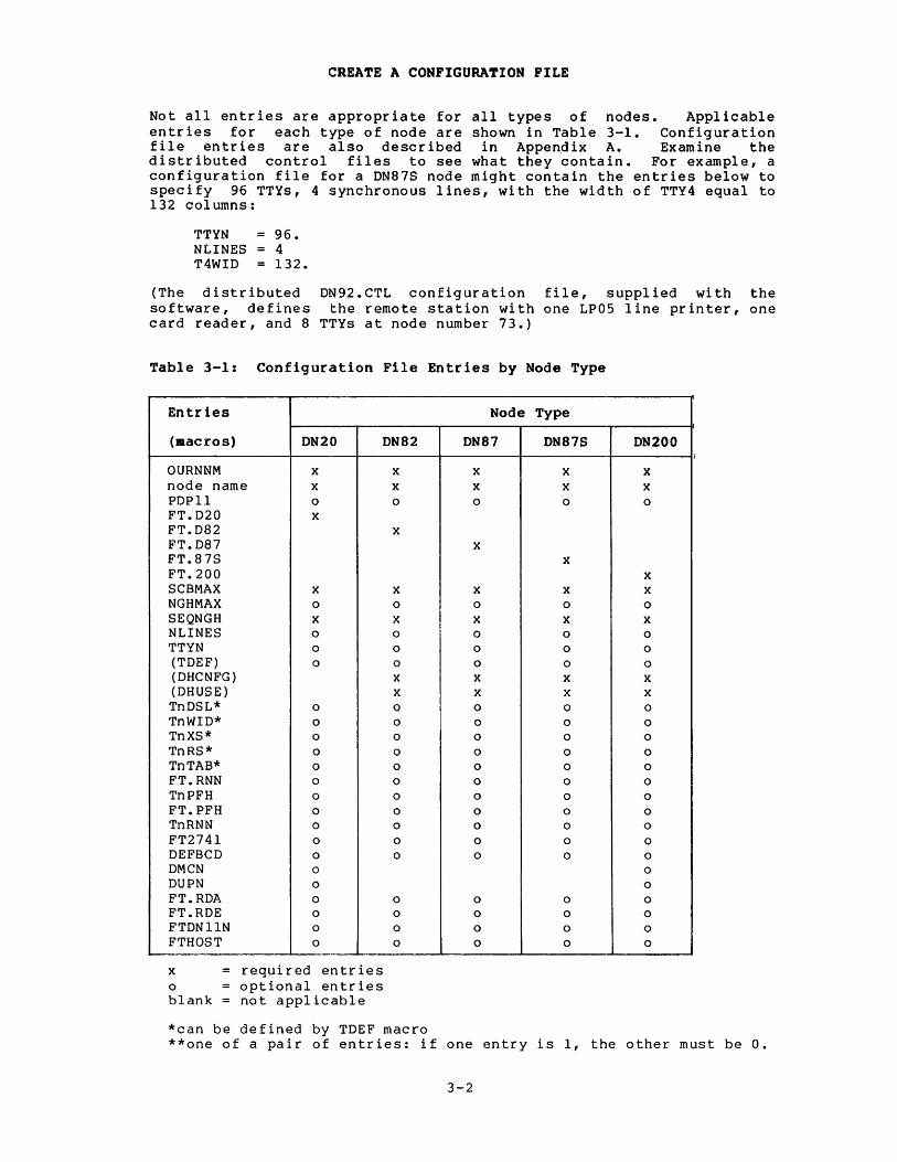
Not all entries are appropriate for all types of nodes. Applicable entries for each type of node are shown in Table 3-1. Configuration file entries are also described in Appen~ix A. Examine the distributed control files to see what they contain. For example, a configuration file for a DN87S node might contain the entries below to specify 96 TTYs, 4 synchronous lines, with the width of TTY4 equal to 132 columns:
TTYN 96. NLINES 4 T4WID 132.
(The distributed DN92.CTL configuration file, supplied with the software, defines the remote station with one LP05 line printer, one card reader, and 8 TTYs at node number 73.)
Table 3-1: Configuration File Entries by Node Type
Entr.ies Node Type
(macros) DN20 DN82 DN87 DN87S DN200 i
OURNNM x x x x x node name x x x x x PDPll 0 0 0 0 0
FT.D20 x FT.D82 x FT.D87 x FT.87S x FT.200 x SCBMAX x x x x x NGHMAX 0 0 0 0 0
SEQNGH x x x x x NLINES 0 0 0 0 0
TTYN 0 0 0 0 0
(TDEF) 0 0 0 0 0
(DHCNFG) x x x x (DHUSE) x x x x TnDSL* 0 0 0 0 0
TnWID* 0 0 0 0 0
TnXS* 0 0 0 0 0
TnRS* 0 0 0 0 0
TnTAB* 0 0 0 0 0
FT.RNN 0 0 0 0 0
TnPFH 0 0 0 0 0
FT.PFH 0 0 0 0 0
TnRNN 0 0 0 0 0
FT2741 0 0 0 0 0
DEFBCD 0 0 0 0 0
DMCN 0 0
DUPN 0 0
FT.RDA 0 0 0 0 0 FT.RDE 0 0 0 0 0
FTDNllN 0 0 0 0 0
FTHOST 0 0 0 0 0
x required entries o optional entries blank not applicable
*can be defined by TDEF macro **one of a pair of entries: if one entry is 1, the other must be O.
3-2
CREATE A CONFIGURATION FILE
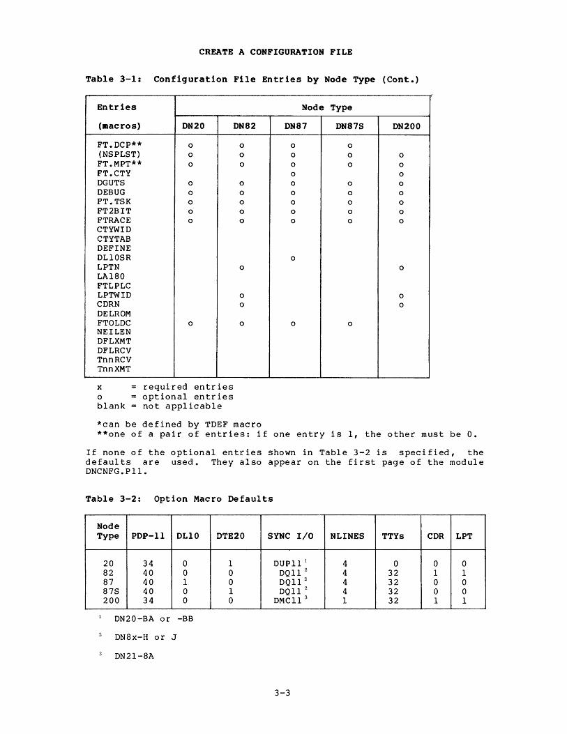
Table 3-1: Configuration File Entries by Node Type (Cont.)
I
Entries Node Type
(macros) DN20 DN82 DN87 DN87S DN200
FT.DCP** 0 0 0 0
(NSPLST) 0 0 0 0 0
FT.MPT** 0 0 0 0 0
FT.CTY 0 0
DGUTS 0 0 0 0 0
DEBUG 0 0 0 0 0
FT.TSK 0 0 0 0 0
FT2BIT 0 0 0 0 0
FTRACE 0 0 0 0 0
CTYWID CTYTAB DEFINE DLIOSR 0
LPTN 0 0
LA180 FTLPLC LPTWID 0 0 CDRN 0 0
DELROM FTOLDC 0 0 0 0 NEILEN DFLXMT DFLRCV TnnRCV TnnXMT
x required entries o optional entries blank not applicable
*can be defined by TDEF macro **one of a pair of entries: if one entry is 1, the other must be O.
If none of the optional entries shown in Table 3-2 is specified, the defaults are used. They also appear on the first page of the module DNCNFG.Pll.
Table 3-2: Option Macro Defaults
Node Type PDP-II OLIO DTE20 SYNC I/O NLINES TTYs CDR LPT
20 34 0 I DUPII 1 4 0 0 0 82 40 0 0 DQl1 2 4 32 I I 87 40 I 0 DQl1 2 4 32 0 0 87S 40 0 I OQl12 4 32 0 0 200 34 0 0 OMCl1 3 I 32 I I
DN20-BA or -BB
ON8x-H or J
DN21-8A
3-3
CREATE A CONFIGURATION FILE
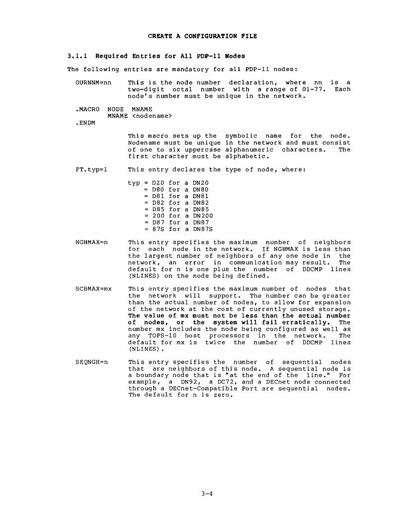
3.1.1 Required Entries for All PDP-II Modes
The following entries are mandatory for all PDP-II nodes:
OURNNM=nn This is the node number declaration, where nn two-digit octal number with a range of 01-77. node's number must be unique in the network •
is a Each
• MACRO NODE MNAME MNAME <nodename>
.ENDM
FT.typ=l
NGHMAX=n
SCBMAX=mx
SEQNGH=n
This macro sets up the symbolic name for the node. Nodename must be unique in the network and must consist of one to six uppercase alphanumeric characters. The first character must be alphabetic.
This entry declares the type of node, where:
typ 020 for a DN20 080 for a DN80 081 for a DN81 082 for a DN82 085 for a DN85 200 for a DN200 087 for a ON87 87S for a ON87S
This entry specifies the maximum number of neighbors for each node in the network. If NGHMAX is less than the largest number of neighbors of anyone node in the network, an error in communication may result. The default for n is one plus the number of OOCMP lines (NLINES) on the node being defined.
This entry specifies the maximum number of nodes that the network will support. The number can be greater than the actual number of nodes, to allow for expansion of the network at the cost of currently unused storage. The value of mx must not be less than the actual number of nodes, or the system will fail erratically. The number mx includes the node being configured as well as any TOPS-IO host processors in the network. The default for mx is twice the number of DOCMP lines (NLINES) •
This entry specifies the number of sequential nodes that are neighbors of this node. A sequential node is a boundary node that is "at the end of the line." For example, a ON92, a OC72, and a OECnet node connected through a DECnet-Compatible Port are sequential nodes. The default for n is zero.
3-4

CREATE A CONFIGURATION FILE
3.1.2 Synchronous Line Entry
The following entry defines the synchronous lines on each node:
NLINES=#sy This entry specifies the number of synchronous lines attached to the node. If omitted, any PDP-II based node is built for four synchronous lines. NLINES can be 0 (for a DN20, DN87, or DN87S front end supporting only asynchronous lines) to a maximum of 10 for a DN87, or 12 for a DN20, DN200, DN85, or DN87S. This entry does not apply to the DN92 since it can have only one synchronous line. If a node has more than one type of synchronous line, line numbers are assigned in the following order:
DQll DMCll/DMRll DUPll DSll DUll DPll DVll
For example, if a DN20 has 2 DMCll/DMRlls and 2 DUPlls, the DMClls are lines 0 and 1 and the DUPlls are lines 2 and 3.
3.1.3 Asynchronous Line and Terminal Entries
The following entries define the characteristics of asynchronous lines on each node and of terminals attached to each line:
TTYN=#as This entry specifies the total number of asynchronous terminal lines attached to the node. Code is generated for a maximum number of asynchronous lines (#as) numbered 0 to #as-l, excluding the CTY. The number of #as includes the CTY if you specify FT.CTY. If there is a CTY, it is on line O. If this entry is omitted, the default number of lines, shown in Table 3-2, will be used. The allowable values for TTYN vary from 0 to 96 for a DN87, and 0 to 128 for a DN20, DN200, or DN87S.
Line numbers, used in the context of this manual, refer to local lines on the network nodes, and can be in the range 0 to 177. These local line numbers are not the same as the TTYmmm numbers that appear in the configuration messages sent by a host's front end at startup time. TTYmmm numbers are assigned dynamically by the host when the terminal connects to the host. When you give a line number, omit leading zeroes.
3-5

CREATE A CONFIGURATION FILE
Each of the terminals declared in the TTYN entry has the following default characteristics:
• hard-wired (as opposed to dataset line)
• 72-column width
• autobaud detection
• no hardware tabs
• may be assigned by any network node
• is not an IBM 274l-type terminal
NOTE
To indicate that a terminal is an IBM 274l-type, give its speed as 134. baud; turn on FT274l=1 and include module DN2741.Pll (see Section 3.1.4).
To override any of the above defaults, use one or more of the entries listed below. Any of the following entries, of the form Tnxxx, can also be specified using generic terms. When the entry applies to the console terminal, use CTY.
TnDSL=l
TnWID=w
TnXS=s TnRS=s
This entry specifies that line n is a dataset line and connects to a terminal with a modem rather than being hardwired. One such entry is required for each dataset line.
This entry specifies that the line n has a column width of the default of 72. One entry terminal with a nondefault column width is 255 columns.
terminal connected to w characters rather than is required for each
column width. Maximum
This pair of entries specifies the transmit speed (XS) and receive speed (RS) for an asynchronous line~ Transmit speed is the speed from the node processor to the terminal; receive speed is the speed from the terminal to the node processor. The line number, n, must be in octal. The speed of the line in baud, s, is usually entered in decimal. If both speeds are the same (as in DZII lines), you need only specify one speed.
Acceptable line speeds (in baud) are:
50. 75.
110. 134.* 150. 200. 300.
600. 1200. 1800. 2400. 4800. 9600.
* Use this lins speed only for IBM 274l-type terminals.
3-6
TnTAB=l
CREATE A CONFIGURATION FILE
If only the transmit speed is defined, the receive speed defaults to the same value. If the terminal is a split-speed terminal, both TnXS and TnRS must be specified for that line.
NOTE
Different transmit and receive speeds cannot be defined for terminals assigned to asynchronous DZll lines. DZll lines are usually formed in DN20 and DN200 nodes.
If the terminal is hardwired and is always set for a particular line speed, you may want to use these entries to set the line speed to the specified value when the node is reloadede
This entry specifies that line n has hardware tabs. such terminal.
the terminal connected to One entry is needed for each
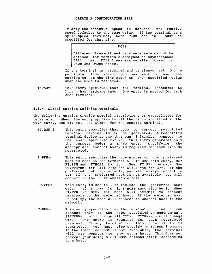
3.1.4 Global Entries Defining Terminals
The following entries provide special restrictions or capabilities for terminals. When the entry applies to all the lines specified in the TTYN entry, use TTYxxx. Use CTYxxx for the console terminal.
FT.RNN=l
TnPFH=nn
FT.PFH=O
TnRNN=nn
This entry specifies that code to support restricted terminal devices is to be generated. A restricted terminal device is one that can initially connect to the host specified for it. This entry generates only the support code; a TnRNN entry, specifying the appropriate control host, is required for each line so restricted.
This entry specifies the node number of the preferred host as node nn for terminal n. To use this entry, set FT.PFH and FTHOST to l~ (See FT.PFH below.) Use TTYPFH=nn for all TTYs and CTYPFH=nn for CTY. If the preferred host is available, you will always connect to it; if the preferred host is not available, you will connect to the first available host.
This entry is set to 1 to include the preferred host code. If FT.PFH is 1, FTHOST must also be 1. When FT.PFH is set, the node will attempt to connect terminals to the preferred host. If the preferred host is not up, the node will connect to another host in the network.
This entry specifies that the terminal on line n can connect only to the host specified by nodenum(nn) • (TTYRNN=nn will change all TTYs. CTYRNN=nn will change CTY.) One entry is required for each restricted terminal. If any terminal on this node is to be restricted, you must also specify an FT.RNN=l entry. If the specified host is not available, the terminal will not connect to any other host. This does not prevent your doing a SET HOST command after connecting to a host.
3-7

CREATE A CONFIGURATION FILE
FT274l=1 This entry specifies that code to support IBM 274l-type terminals is to be generated. If this switch is omitted, FT2741 assumes a value of O.
DEFBCD=bll. This entry specifies the default type element (ball) for all the IBM 274l-type terminals on this node. Acceptable values for bll. are:
938. BCD 963. EBCDIC 987. APL correspondence 9£8. APL (EBCDIC)
Individual 274l-type terminals on this node can use elements other than the default by invoking the SET TTY ELEMENT monit~r command. The default element is 988 ••
3.1.5 Global Entries that Change the Network Environment
The following entries to the configuration file are optional and are used to create special operating environments, set rules of protocol, or invoke special network features.
DLlOSR=164000
DMCN=n
DUPN=n
FT.RDA=l
FT.RDE=l
FTDMll=l
FTDNll=l
FTHOST=O
This entry enables CHKll to find a DLIO in a DN87 front end with 32K-word memory. This is the address at which DDTll stops scanning for a DLIO. Set it equal to or higher than the DLIO address.
This entry specifies the number of DMClls connected to a DN20 or a DN200.
This entry specifies the number of DUPlls connected to a DN20 or a DN200.
This entry specifies that code to support ASCII remote data entry devices is to be generated. If this entry is not present, the code is not generated.
This entry specifies that code to support multidrop remote data entry pseudo devices is to be generated. If this entry is not present, the code is not generated.
This entry is DMll/DHll lines. node, set FTDMll you use DHlls. defined.
set to include the modem code for If there are no dial-in lines on this
to o. You should set this to 1 when The default value is 1 if DHlls are
This entry specifies that code to support the DNll automatic-dialing interface device is to be generated. If this entry is not present, the code is not generated.
This entry suppresses code needed for the SET HOST monitor command. If this entry is not present, code to support the SET HOST command is generated.
3-8

FT.MPT=1
FT.CTY=1
DGUTS=1
FT.TSK=1
FT2BIT=1
FTOLDC=1
PDPII=nn
CREATE A CONFIGURATION FILE
This entry specifies that code to support multidrop (multipoint) lines is to be generated. If this entry is not present, the code will not be generated. Use this entry with RDX devices.
NOTE
To generate multidrop support, include the source modules DNCDDH.PII and DNRDE.PII in the MACDLX assembler input list.
This entry specifies that code to support the use of the timesharing terminal on the DLII asynchronous line interface as a TOPS-IO terminal is to be generated. CHKII output generated at node startup time is always output on the DLII.
This entry specifies that error recovery code is to be generated. When this code is active, the node will attempt to recover from "soft!' errors. Soft errors include lack of buffer or table space and incorrect message formats. Hard errors, such as functionally inoperative hardware, are still fatal. Note that when this recovery feature is activated, certain debugging facilities such as the ASSERT and TWIDDL macros are disabled. If this entry is not present, all errors are fatal, and no error recovery is attempted; however, full debugging facilities are available. It is recommended that this feature test switch be set off (DGUTS=O) •
This entry generates code to support the scheduling of special-purpose user tasks in the PDP-II while the node is running. If this entry is not present, the code is not generated.
This entry determines the mlnlmum length of the stop bit on terminal lines operating at 300 baud or faster. The default value of I (ON) sets the stop bit to twice the length of a data bit. A value of 0 (OFF) sets the stop bit to the length of a data bit. At line speeds under 300 baud, the minimum length of the stop bit is always twice the length of a data bit. FT2BIT=0 may provide more throughput than FT2BIT=1 but this setting is incompatible with some terminals.
This entry specifies that this node is to be generated with the version of DDCMP protocol used prior to Version 6.03 of TOPS-IO. The default value is 0 (OFF). If you are running Version 6.03 or later, do not include this entry.
This entry specifies the model number of the node's PDP-II processor. For example, use PDPII=40 for a DN80-series node, or PDPII=34 for a DN20 and DN200 node (see Table 3-2).
Other entries for PDP-II-based nodes are described in Appendix A.
3-9
CREATE A CONFIGURATION FILE
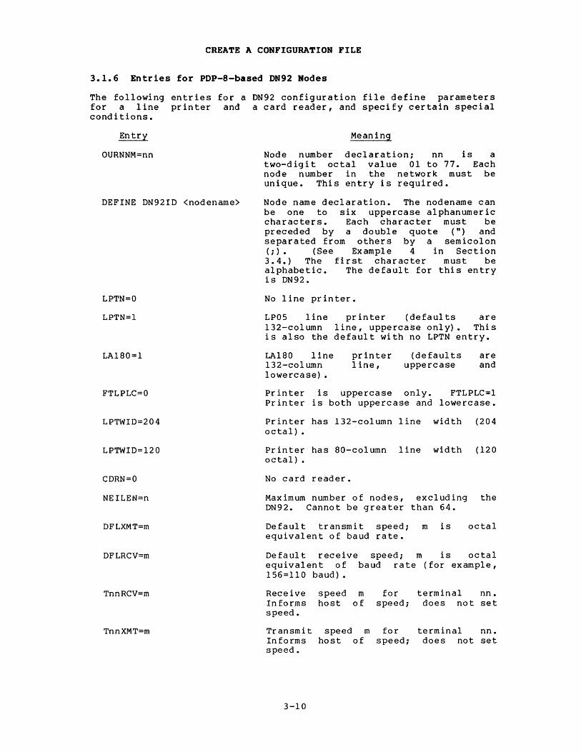
3.1.6 Entries for PDP-8-based DN92 Nodes
The following entries for a DN92 configuration file define parameters for a line printer and a card reader, and specify certain special conditions.
Entry
OURNNM=nn
DEFINE DN92ID <nodename>
LPTN=O
LPTN=l
LA180=1
FTLPLC=O
LPTWID=204
LPTWID=120
CDRN=O
NEILEN=n
DFLXMT=m
DFLRCV=m
TnnRCV=m
TnnXMT=m
Meaning
Node number declaration; nn is a two-digit octal value 01 to 77. Each node number in the network must be unique. This entry is required.
Node name declaration. The nodename can be one to six uppercase alphanumeric characters. Each character must be preceded by a double quote (") and separated from others by a semicolon (;) • (See Example 4 in Section 3.4.) The first character must be alphabetic. The default for this entry is DN92.
No line printer.
LP05 line printer (defaults are 132-column line, uppercase only). This is also the default with no LPTN entry.
LA180 line l32-column lowercase) •
printer (defaults line, uppercase
are and
Printer is uppercase only. FTLPLC=l Printer is both uppercase and lowercase.
Printer has l32-column line width (204 octal) •
Printer has 80-column line width (120 octal) •
No card reader.
Maximum number of nodes, excluding the DN92. Cannot be greater than 64.
Default transmit speed; m is equivalent of baud rate.
octal
Default receive speed; m is octal equivalent of baud rate (for example, 156=110 baud).
Receive speed m for terminal nne Informs host of speed; does not set speed.
Transmit speed m for terminal nne In forms host of speed; does not set speed.
3-10

CREATE A CONFIGURATION FILE
Entry
DELROM=l
FTOLDC=l
Meaning
System should print an error message and halt if an error occurs in the DN92; if this line is not placed in the configuration file, the DN92 is rebooted from its ROM.
This entry specifies that this node is to be generated with the version of DDCMP protocol used prior to Release 6.03 of TOPS-10. The default value is 0 (OFF). If you are running Version 6.03 or later, do not include this entry.
3.1.6.1 DN92 Configuration File Defaults - If no configuration file is specified for a DN92 remote station assembly, the software automatically assembles a remote node with node number=72i 8 TTYsi one card reader; and one l32-column, uppercase-only, LP05 line printer. The default switches are summarized below.
Switch
OURNNM= DEFINE DN92ID< > NEILEN= TTYN= TnnWID= CTYWID= LPTN= LA180= FTLPLC= LPTWID= CDRN= DFLXMT DFLRCV
Defaul t
72 DN92 16 10 (octal) (8. TTYs) 72 72 1 o o 204 (octal) (132. columns) 1 If omitted, 110 baud. If omitted, default is DFLXMT.
3.2 CONFIGURATION-DEFINING MACROS FOR PDP-ll-BASED NODES
Place TDEF, DHCNFG, and DHUSE macros in your C.Pll module to provide special definitions for your asynchronous lines and terminals. These macros are defined in the DNCNFG.Pll module.
Use the NSPLST macro in C.Pll whenever a node supports one or more DECnet-Compatible Ports (synchronous lines). The NSPLST macro is defined in the C.Pll module.
3-11

CREATE A CONFIGURATION FILE
3.2.1 The TDEF Macro
The TDEF macro is an alternate way to define the terminal characteristics described in Section 3.1.3. Use it only if the node includes asynchronous terminals on DHll or DZl1 lines, and only if you are defining terminals with other than the default attributes, which are listed in Section 3.1.3. The form of the macro is:
TDEF index,<list)
where:
index
list
For example,
TINDX=4
is a symbol representing the local line number n being defined. The value is in octal. Set this symbol initially equal to the first line you want to define. Each additional TDEF macro increments the index. TINDX is the recommended symbol name.
is a list of entries of the form xxx or <xxx,value) where:
xxx is the two- or three-character identifier in the Tnxxx entry.
value is the value to be assigned to the Tnxxx entry. If value is omitted, the entry is given the value 1.
TDI~F TINDX, «RS, 2400.), <WID, 80.), TAB) TDEF TINDX,<DSL,<RNN,lO»
defines the following entries:
T4RS=2400. T4WID=80. T4TAB=1 T5DSL=1 T5RNN=10
NOTE
An asynchronous terminal assigned to a DZll line will not function properly if the defined transmit and receive speeds differ. The DZll interface does not support split speeds.
3.2.2 The DHCNFG Macro
Place a OHCNFG macro definition in your configuration file (C.Pll) to define the attributes of OHll or OZll lines by using calls to the TOEF mac ro.
3-12

CREATE A CONFIGURATION FILE
Note the following example:
.MACRO DHCNFG TINDX=6 TDEF TINDX,«RS,150.>,<XS,2400.» TDEF TINDX,«RS,150.>,<XS,2400.» TDEF TINDX,«RS,150.>,<XS,2400.» TINDX=12 TDEF TINDX,«RS,2400.» TDEF TINDX,«RS,2400.» TINDX=50 TDEF TINDX,«RS,300.» TDEF TINDX,«RS,300.» TDEF TINDX,«RS,300.» TDEF TINDX,«WID,aO.>,TAB,DSL> DHUSE (NTT,NAL,NMPT,TRIB,RDPN,RDAN) .ENDM
;set index to 6 ;line 6 ;line 7 ;line 10 (octal) ;set index to 12 (octal) ;line 12 ;line 13 ;set index to 50 ;line 50 ;line 51 ;line 52 ;line 53 ;see Section 3.2.3
The above entries define the following asynchronous lines:
Line No. Nondefault Attributes
6 split baud, 150 receive/2400 transmit 7 split baud, 150 receive/2400 transmit
10 split baud, 150 receive/2400 transmit 12 2400 baud, receive and transmit 13 2400 baud, receive and transmit 50 300 baud, receive and transmit 51 300 baud, receive and transmit 52 300 baud, receive and transmit 53 dataset line, hardware tabs, and aO-column line width
3.2.3 The DHUSE Macro
Whenever you have asynchronous lines attached to a node, you must define a DHUSE macro in your DHCNFG macro. This is true even if all the lines and terminals are to assume the default characteristics. All but the first and last arguments in the list apply only to DDCMP asynchronous lines and are usually set to O. ROAN is for RDA devices.
The format of the DHUSE macro is as follows:
DHUSE (NTT,NAL,NMPT,TRIB,RDPN,RDAN) where:
NTT
NAL
NMPT
TRIB
RDPN
RDAN
is the number specified as 3-2.
of terminals. This argument can be TTYN to use the defaults given in Table
is the number of asynchronous point-to-point DDCMP lines.
is the number of multipoint DHll or DZl1 lines.
is the number of multipoint tributary DHll or DZl1 lines.
is the number of point-to-point DDCMP remote data entry devices.
is the number of ASCII remote data entry devices.
3-13

CREATE A CONFIGURATION FILE
For example, a node with 64 (decimal) terminals, all taking default characteristics, can be defined in the configuration file with the following entries:
.MACRO DHCNFG DHUSE (64.,0,0,0,0,0) .ENDM
;64. is number of terminals in decimal
3.3 SAVE THE CONFIGURATION FILE
When you have entered all the applicable entries to file, save it in your disk area. Chapter 4 configuration file is used in the assembly command editor is one that provides line numbering, such as without the line numbers.
the configuration describes how the string. If the
80S, save the file
3.4 EXAMPLES OF CONFIGURATION FILES
The following examples are included to· provide you with reference material as you generate your configuration files.
Example 1
Create a configuration file for a DN20 front end at node 16 that supports 4 low-speed synchronous lines (DUPlls) and 64 terminal lines (DZlls) ~ (The $ used to exit from SOS is the echo of the ESCape (ALTMODE) key.)
.SOS DN20l6.Pll Input: DN2016.Pll 00100 OURNNM=16 00200 .MACRO NODE MNAME 00300 MNAME <SEN> 00400 .ENDM 00500 FT.D20=1 00600 SCBM~X=25. 00700 DUPN=4 00800 NLINES=DUPN 00900 FTHOST=l 01000 FT.CTY=O 01100 FT.RNN=l 01200 TTYRNN=26 01300 CTYRNN=26 01400 TTYN=64. 01500 .MACRO DHCNFG 01600 TINDX=O
iThis is node #16
iThis is node name SEN
iThis is a DN20 with a DTE20 iMaximum of 26 nodes in the network i4 DUPll synchronous lines iNumber of synchronous lines iTurn on SET HOST capability iNo DN20 CTY, DLll goes to 20F CTY ;Turn on the Restricted Node code iAll TTYs are restricted to node 26 ion the initial connect, so is CTY ;64 DZll TTY lines
01700 TDEF TINDX,«XS,9600.>,<WID,80.» 01800 TDEF TINDX,<DSL> 01900 TINDX=40 02000 TDEF TINDX,«XS,2400.>,<WID,80.» 02100 TINDX=46 02200 TDEF TINDX,<DSL> 02300 TDEF TINDX,<DSL> 02400 TDEF TINDX,<DSL> 02500 DHUSE (TTYN,O,O,O,O,O) 02600 .ENDM DHCNFG 02700 $ *ES
[DSKC:DN2016.Pll[30,5520]]
3-14

CREATE A CONFIGURATION FILE
Example ~
Create a configuration file for a DNB7S front end at node 16 to support one synchronous line and a maximum of 60 asynchronous lines for local terminals. Some of the local terminals are to have other than default characteristics •
• SOS DNB747.Pll Input: DNB747.Pll 00100 OURNNM=47; 00200 .MACRO NODE 00300 MNAME 00400 .ENDM 00500 FT.B7S=1 00600 SCBMAX=25. 00700 FTHOST=l OOBOO TTYN=64. 00900 FT.PFH=l 01000 TTYPFH=26 01100 CTYPFH=26 01200 FTDMll=O 01300 DMCN=l 01400 DQN=2 01500 NLINES=DQN+DMCN 01600 FT.CTY=O 01700 FT274l=0 OIBOO .MACRO DHCNFG 01900 TINDX=O 02000 .REPT 60 02100 TDEF 02200 .ENDR 02300 .REPT 4 02400 TDEF 02500 .ENDR 02600 .REPT 4 02700 TDEF 02BOO • ENDR 02900 .REPT B. 03000 TDEF 03100 • ENDR 03200 DHUSE 03300 .ENDM DHCNFG 03400 $ *ES
;This is node number 47 MNAME <HANLEY) ;This is node name HANLEY
; Th is is a ON B 7S ;Maximum of 26 nodes in the network ;Turn on SET HOST capability ;64 TTYs on DHlls ;Turn on Preferred Host code ;All TTYs connect to node 26 if free ;Same for CTY ;No "DHll/DMll" datasets ;One DMCll synchronous line ;Two DQll synchronous lines ;Number of synchronous lines ;DLll is connected to the 20F CTY ;No 2741 TTYs
;Starting at DH #0, line #0 ;48. lines
TINDX,«XS,300.),<RS,300.» ;all 300 baud
;We have 4 lines TINDX,«XS,9600.),<RS,9600.» ;of 9600 baud
;We then have 4 lines TINDX,«XS,4800.),<RS,4BOO.» ;of 4800 baud
;And finally, we have 8 lines TINDX,«XS,2400.),<RS,2400.» ;of 2400 baud
TTYN,O,O,O,O,O
[DSKC:DNB747.Pll[30,5520]]
3-15
CREATE A CONFIGURATION FILE
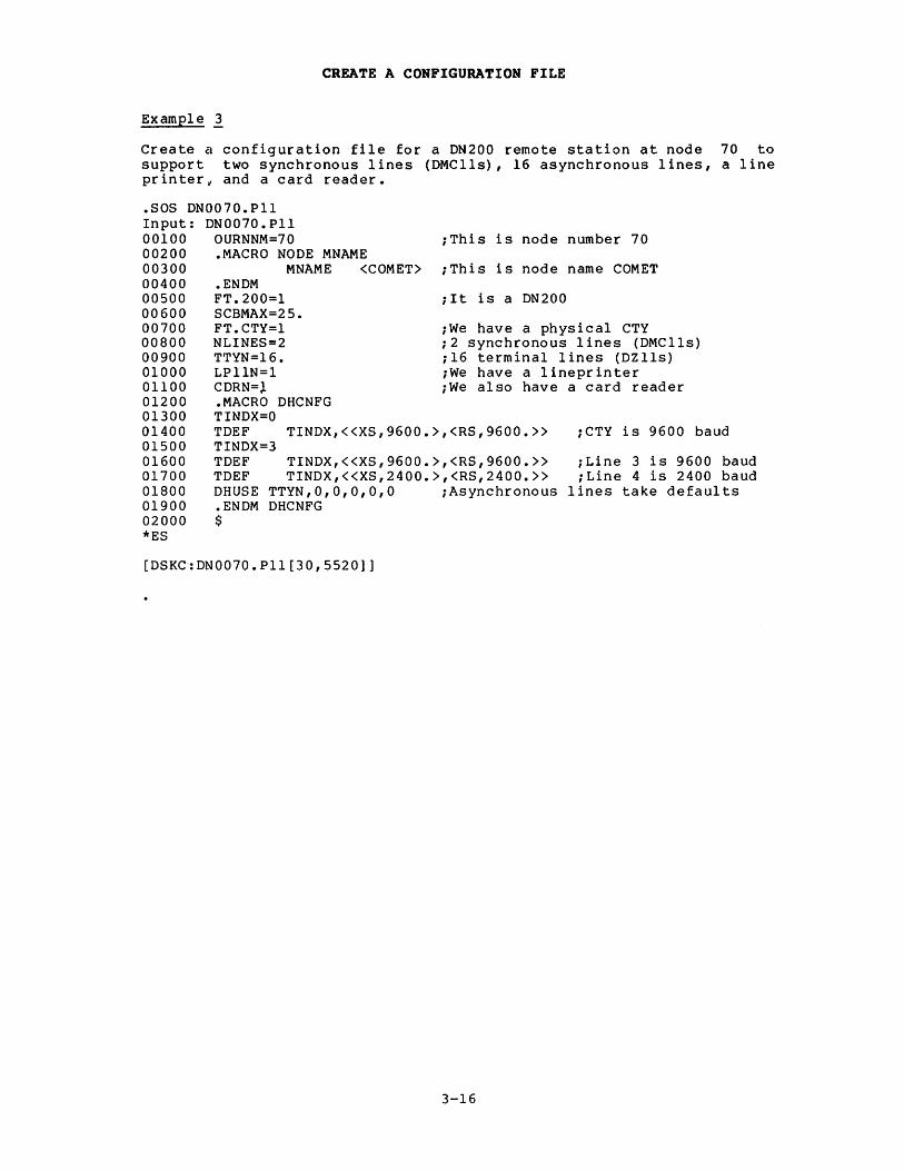
Example 1
Create a configuration file for a DN200 remote station at node 70 to support two synchronous lines (DMClls), 16 asynchronous lines, a line printer v and a card reader •
• 808 DN0070.Pll Input: DN0070.Pll 00100 OURNNM=70 00200 .MACRO NODE MNAME 00300 MNAME <COMET> 00400 • ENDM 00500 FT.200=1 00600 SCBMAX=25. 00700 FT.CTY=l 00800 NLINES=2 00900 TTYN=16. 01000 LPIlN=l 01100 CDRN=l 01200 .MACRO DHCNFG
;This is node number 70
;This is node name COMET
; I tis a DN 200
;We have a physical CTY ;2 synchronous lines (DMClls) ;16 terminal lines (DZlls) ;We have a lineprinter ;We also have a card reader
01300 TINDX=O 01400 TDEF 01500 TINDX=3 01600 TDEF 01700 TDEF 01800 DHUSE 01900 • ENDM 02000 $
TINDX,«XS,9600.>,<RS,9600.» ;CTY is 9600 baud
TINDX,«XS,9600.>,<RS,9600.» ;Line 3 is 9600 baud TINDX,«XS,2400.>,<RS,2400.» ;Line 4 is 2400 baud
TTYN,O,O,O,O,O ;Asynchronous lines take defaults DHCNFG
*ES
[DSKC:DN0070.Pll[30,5520]]
3-16

CREATE A CONFIGURATION FILE
Example!
Create a configuration file for a DN92 remote station at node 44 to support eight TTYs and one LP05 line printer •
• R SOS
FILE: DN9244.PAL INPUT: DN9244.PAL 00100 TTYN=lO 00200 OURNNM=44 00300 DEFINE DN92ID<"N;"E;"W;"N;"O;"D> 00400 CDRN=O 00500 LPTN=l 00600 $ *ES
[DSKC:DN9244.PAL]
3-17
i 10 (octal) terminals iNode number = 44 ;Name = NEWNOD iNo card reader iOne line printer

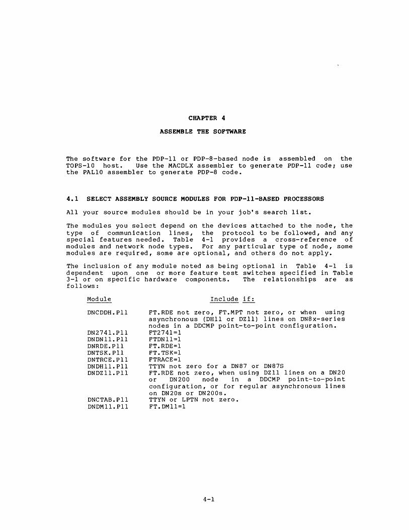
CHAPTER 4
ASSEMBLE THE SOFTWARE
The software for the PDP-II or PDP-8-based node is assembled on the TOPS-IO host. Use the MACDLX assembler to generate PDP-II code; use the PALlO assembler to generate PDP-8 code.
4.1 SELECT ASSEMBLY SOURCE MODULES FOR PDP-II-BASED PROCESSORS
All your source modules should be in your job's search list.
The modules you select depend on the devices attached to the node, the type of communication lines, the protocol to be followed, and any special features needed. Table 4-1 provides a cross-reference of modules and network node types. For any particular type of node, some modules are required, some are optional, and others do not apply.
The inclusion of any module noted as being optional in Table 4-1 is dependent upon one or more feature test switches specified in Table 3-1 or on specific hardware components. The relationships are as follows:
Module
DNCDDH.Pll
DN274l. Pll DNDN 11. Pll DNRDE.Pll DNTSK.Pll DNTRCE.Pll DNDH11.P11 DND211.Pll
DNCTAB.P11 DNDM11.P1l
Include if:
FT.RDE not zero, FT.MPT not zero, or when using asynchronous (DHll or D2ll) lines on DN8x-series nodes in a DDCMP point-to-point configuration. FT274l=1 FTDNll=l FT.RDE=l FT.TSK=l FTRACE=l TTYN not zero for a DN87 or DN87S FT.RDE not 7.ero, when using D211 lines on a DN20 or DN200 node in a DDCMP point-to-point configuration, or for regular asynchronous lines on DN20s or DN200s. TTYN or LPTN not zero. FT.DMl1=1
4-1

ASSEMBLE THE SOFTWARE
Table 4-1: Assembly Modules by Node Type
Type of Node
Module DN20 DN82 DN87 DN87S DN200
C.PII x x x x x S.PII x x x x x MACROS.PII x x x x x DNCNFG.PII x x x x x DNCOMM.PII x x x x x DNNCL.PII x x x x x DNDEV.PII x x x x x DNDCMP.PII 0 x x x x DNDLIO.PII x DNDTE.PII x x DNCDDQ.PII x 0 0
DNCDDH.PII 0 0 0
DNCDUP.PII 0 x DNDMII. PII 0 0 0
DNDHII. PII x 0 0
DNDZII.PII 0 0
DNTTY.PII x x 0 0 0
DN2741.PII 0 0 0 0 0
DNCTAB.PII 0 x 0 0 0
DNDNII. PII 0 0 0 0 0
DNRDA.PII 0 0 0 0 0
DNRDE.PII 0 0 0 0 0
DNLPT.PII x 0
DNCRD.PII x 0
DNTSK.PII 0 0 0 0 0
DNTRCE.PII 0 0 0 0 0
DNDBG.PII 0 0 0 0 0
DNLBLK. PII x x x x x CHKII.PII x x x x x
x These modules are required for this type of node. o These modules are optional for this type of node.
blank These modules do not apply to this type of node.
4.2 ASSEMBLE SOFTWARE FOR PDP-II-BASED PROCESSORS
The general MACDLX command string for assembling PDP-II node software is:
*dev:binfile.ext,dev:lstfile.ext/CRF=dev:srcfile.ext, ••
where:
dev:
binfile.ext
lstfile.ext
is the physical or logical device on which the input or output files are or will be located. If dey: is omitted, DSK: is assumed.
is the output binary program file. If .ext is omitted, .BIN is assumed.
is the output program listing file. If .ext is omi tted, • LST is assumed.
4-2
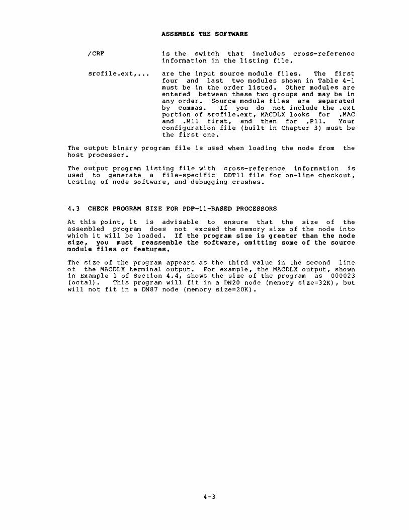
/CRF
srcfile.ext, •••
ASSEMBLE THE SOFTWARE
is the switch that includes cross-reference information in the listing file.
are the input source module files. The first four and last two modules shown in Table 4-1 must be in the order listed. Other modules are entered between these two groups and may be in any order. Source module files are separated by commas. If you do not include the .ext portion of srcfile.ext, MACDLX looks for .MAC and .Mll first, and then for .Pll. Your configuration file (built in Chapter 3) must be the first one.
The output binary program file is used when loading the node from the host processor.
The output program listing file with cross-reference information is used to generate a file-specific DDTll file for on-line checkout, testing of node software, and debugging crashes.
4.3 CHECK PROGRAM SIZE FOR PDP-II-BASED PROCESSORS
At this point, it is advisable to ensure that the size of the assembled program does not exceed the memory size of the node into which it will be loaded. If the program size is greater than the node size, you must reassemble the software, omitting some of the source module files or features.
The size of the program appears as the third value in the second line of the MACDLX terminal output. For example, the MACDLX output, shown in Example 1 of Section 4.4, shows the size of the program as 000023 (octal) • This program will fit in a DN20 node (memory size=32K), but will not fit in a DN87 node (memory size=20K) •
4-3

ASSEMBLE THE SOFTWARE
4.4 EXAMPLES FOR PDP-II-BASED PROCESSORS
The following examples show the successful assembly of the software for three PDP-II-based nodes. When you give the MACDLX command string, do not type a carriage return ~ until after you have entered the last source module file name (CHKII.PII).
Example 1
Assemble the software for a DN20 front end at node 16. The configuration file DN2016 is taken from Example 1 of Section 3.4 •
• R MACDLX ~
*DN2016,DN2016.CRF/CRF=DN2016,S,MACROS,DNCNFG,DNCOMM,DNNCL, DNDEV,DNDCMP,DNDTE,DNCDUP,DNDZll,DNTTY,DNCTAB,DNLBLK,CHKll ~
18218 077132 000020 in octal K words 22187 112232 000023 in octal K words
ERRORS DETECTED: 0
.PRINT Q isize of program
.PRINT CHKSIZ isize of program
DN2016,DN2016.CRF/CRF=DN2016,S,MACROS,DNCNFG,DNCOMM,DNNCL,DNDEV DNDCMP,DNDTE,DNCDUP,DNDZll,DNTTY,DNCTAB,DNLBLK,CHKll
RUN-TIME: 56 71 RUN-TIME RATIO: CORE USED: 42K
11 SECONDS 1284/140=9.1
(83 PAGES)
4-4

ASSEMBLE THE SOFTWARE
Example ~
Assemble the software for a DN87S front end at node 47. The configuration file DN8747 is taken from Example 2 of Section 3.4 •
• R MACDLX ~
*DN8747,DN8747.CRF/CRF=DN8747,S,MACROS,DNCNFG,DNCOMM,DNNCL,DNDEV, DNDCMP,DNDTE,DNCDDQ,DNCDMC,DNDHll,DNTTY,DNCTAB,DNLBLK,CHKll ~
18443 106134 000022 in octal K words 22412 122040 000025 in octal K words.
ERRORS DETECTED: 0
.PRINT Q isize of program
.PRINT CHKSIZ isize of program
DN8747,DN8747.CRF/CRF=DN8747,S,MACROS,DNCNFG,DNCOMM,DNNCL,DNDEV, DNDCMP,DNDTE,DNCDDQ,DNCDMC,DNDH11,DNTTY,DNCTAB,DNLBLK,CHKll
RUN-TIME: 63 78 12 SECONDS RUN-TIME RATIO: 979/153=6.3 CORE USED: 44K (87 PAGES)
4-5

ASSEMBLE THE SOFTWARE
Example 1
Assemble the software for a DN200 front end at node 27. The configuration file DN0070 is taken from Example 3 of Section 3.4 •
• R MACDLX @D
[S:MACDLX 31(1065} + ] *DN0070, DN0070. CRF /CRF=DN0070, S, MACROS, DNCNFG, DNCOM1-t, DNNCL,
DNDCMP,DNCDMC,DNDEV, DNLPT,DNCRD, DNDZ11,DNTTY,DNRAM,DNV FU,DNCTAB, DNLBLK, CHK11 @D
18086 073010 000017 in octal K words 22055 106144 000022 in octal K words.
ERRORS DETECTED: 0
• PRINT Q isize of program
.PRINT CHKSIZ isize of program
DN0070,DN0070.CRF/CRF=DN0070,S,MACROS,DNCNFG,DNCOMM,DNNCL, DNDCMP,DNCDMC,DNDEV,DNLPT,DNCRD,DNDZ11,DNTTY,DNRAM,DNVFU,DNCTAB, DNLBLK, CHK11
RUN-TIME: 40 56 7 SECONDS RUN-TIME RATIO: 1365/104=13.1 CORE USED: 32K (63 PAGES)
4-6

ASSEMBLE THE SOFTWARE
4.5 EXAMPLES OF SAVING SYMBOLS WITH DDTll
The following examples show the use of DDTII to save symbols for ANF-IO nodes. Saving symbols with DDTII allows you to delete the .CRF file and still be able to examine dump files symbolically. For further information on using DDTII, please refer to the TOPS-IO/TOPS-20 DDTII Manual.
Example I
Extract symbols from the .CRF file for the DN20 node •
• R DDTII ~
DDTII 7E(I06)
Input: DN2016.CRF/SYMBOL ~ [46p core] [47p core] [4Sp core] [49p core] [50p core] [51p core] [52p core] [53p core] [54p core] [55p core] [56p core] [57p core] [5Sp core] [59p core] [60p core] [61p core] [62p core] [63p core] [64p core] [65p core] [66p core] [67p core] [6Sp core] [69p core] [70p core] %Loaded 311S symbols.
Input: A Z
.SSAVE DN2016 ~ DN2016 saved
4-7

ASSEMBLE THE SOFTWARE
Example 2
Extract symbols from the .CRF file for the DNS7S node •
• R DDT11 ~
DDT11 7E(106)
Input: DNS747.CRF/SYMBOL ~ [46p core] [47p core] [4Sp core] [49p core] [SQp core] [SIp core] [S2p core] [S3p core] [S4p core] [SSp core] [S6p core] [S7p core] [SSp core] [S9p core] [60p core] [61p core] [62p core] [6.3p core] [64p core] [6Sp core] [66p core] [67p core] [6Sp core] [69p core] [70p core] [71p core] %Loaded 3271 symbols.
Input: .... Z
.SSAVE DNS747 ~ DNS747 saved
4-S

ASSEMBLE THE SOFTWARE
Example 3
Extract symbols from the .CRF file for the DN200 node •
• R DDTII CillJ
DDTII 7E(I06)
Input: DN0070.CRF/SYMBOL CillJ [46p core] [47p core] [48p core] [49p core] [50p core] [51p core] [52p core] [53p core] [54p cor e] [55p core] [56p core] [57p core] [58p core] [59p core] [60p core] [61p core] [62p core] [63p core] [64p core] [65p core] %Loaded 2444 symbols.
Input: .... Z
.SSAVE DN0070 CillJ DN0070 saved
4-9

ASSEMBLE THE SOFTWARE
4.6 ASSEMBLE SOFTWARE FOR PDP-8-BASED PROCESSORS
Use the PALlO assembler to generate the PDP-8 code. The PALlO assembler can be found on the third saveset of the TOPS-IO Distribution Tape. It is best to run both PALlO and CREF.
To run the assembler, you must have:
DN92.PAL
PALlO.EXE
You can also have:
a configuration file
CREF
DN92 source modules.
The PALlO assembler.
You can use DN92.CTL from the distribution tape if it serves your purposes; otherwise, create your own or alter DN92.CTL to reflect your installation. Without a configuration file, a default node is assembled (see Section 3.1.6.1).
The TOPS-IO cross-reference program should be on your system. Without the CREF program, you cannot obtain a cross-reference listing.
To assemble the software, specify an input string to PALlO in the form:
output-fi1e.BIN,CREF-file.CRF/C=configuration-file.CTL,DN92.PAL
File extensions should be as indicated. You cannot run the cross-reference program unless you specify a CREF filename.
The following example illustrates a successful assembly of the DN92 software. This example illustrates use of a C.PAL configuration file, creation of a binary file called DN9273.BIN, and an output file that can be used to run CREF. It is useful to print the CREF file (as shown in the example) to have a cross-referenced listing for your records. You need this file if you wish to run DDTll. The C.PAL configuration file (part of DN92.CTL) contains the following definitions:
LPTN 1 CDRN 1 TTYN 10 OURNNM 73
~Step 1: Run the PALlO assembler •
• R PALlO ~ *DN9273.BIN,DN9273.CRF/C=C.PAL,DN92.PAL
ERRORS DETECTED: 0 LINKS GENERATED: 629 RUN-TIME: 21 SECONDS 6K CORE USED
*~C
To exit from the PALlO assembler, use CTRL/C.
4-10

ASSEMBLE THE SOFTWARE
.Step 2: Run the cross-reference pr,ogram:
.R CREF ~
*DN9273=DN9273.CRF ~ [CRFXKC 22K core] *"'C
To exit from CREF, use CTRL/C.
When CREF is run, it creates a file called DN9273.LST which can be pr inted •
• Step 3: (optional) Print the CREF output file:
.PRINT DN9273.LST ~ [LPT:DN9273= /Seq:4562/Limit:433, 1 File]
Once this sequence has been completed, you are ready to down-line load the DN92.
4.6.1 Submitting a DN92 Control File
The DN92 distributed software contains a control file called DN92.CTL, which you can use to perform the above assembly automatically.
To use DN92.CTL, use the SUBMIT command:
.SUBMIT DN92.CTL ~ [Batch job DN92 queued, request 727, limit 0:05:00]
You should check your log file to be sure that everything is assembled correctly. Once the control file has executed correctly, you are ready to down-line load the DN92.
4-11


CHAPTER 5
LOAD THE SOFTWARE
This chapter covers the loading of network software into the following types of network nodes:
• local DLIO-interfaced nodes
• local DTE20-interfaced nodes
• remote nodes
It also gives information on loading the KMCll for the 2020.
Installation of software on hosts is covered in the TOPS-IO Software Installation Guide. The operation of and output from the hardware test programs CHKll (for PDP-II-based nodes) and SYSCHK (for PDP-8-based remote nodes) are also described. CHKll (part of DNx code) is invoked whenever a PDP-II-based node is loaded and started; SYSCHK (part of the DN92 code) is invoked whenever a PDP-8-based node is loaded and started. These programs perform initial hardware surveys of the node to ensure that node devices and node memory are functioning correctly.
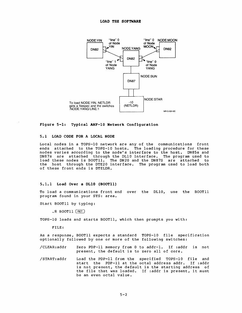
All network nodes except those adjacent to a KSIO host can be loaded from any KLIO host in the TOPS-IO ANF-IO network. A node adjacent to a KSIO must be loaded from the KSIO. To load a remote node, all intervening nodes between it and the host node must be running their respective software. Local nodes (communications front ends) are loaded by either BOOTll, if a DLIO interface is used, or DTELDR, if a DTE20 is used. Remote nodes are loaded by NETLDR. NETLDR loads assembled software through a communications front end (for example, a DN87S) down a specified synchronous line to a remote station (see Figure 5-1). This process is called down-line loading.
5-1
LOAD THE SOFTWARE
NODE:YIN
DN82
"line" 1 ~ of Node YANG
To load NODE:YIN, NETLDR gets a filespec and the switches INODE:YANG/LlNE:1
"line" 0 NODE:MOON of Node
NODE:YANG MOON, DN92
DN82
DN87
-10 (NETLDR)
~"Iine" 0 of Node YANG
NODE:SUN
NODE:STAR
MR-S-S24-S0
Figure 5-1: Typical ANF-lO Network Configuration
5.1 LOAD CODE FOR A LOCAL NODE
Local nodes in a TOPS-IO network are any of the communications front ends attached to the TOPS-IO hosts. The loading procedure for these nodes varies according to the node's interface to the host. ON85s and DN87s are attached through the DLIO interface. The program used to load these nodes is BOOTll. The ON20 and the ON87S are attached to the host through the OTE20 interface. The program used to load both of these front ends is DTELDR.
5.1.1 Load OVer a OLIO (BOOTll)
To load a communications front end over the OLIO, use the BOOTll program found in your SYS: area.
Start BOOTll by typing:
.R BOOTll ~
TOPS-IO loads and starts BOOTll, which then prompts you with:
FILE:
As a response, BOOTll expects a standard TOPS-IO file specification optionally followed by one or more of the following switches:
/CLEAR: add r
/START:addr
Zero PDP-II memory from 0 to addr-l. If :addr is not present, the default is to zero all of core.
Load the PDP-II from the specified TOPS-IO file and start the PDP-II at the octal address addr. If :addr is not present, the default is the starting address of the file that was loaded. If :addr is present, it must be an even octal value.
5-2
/PORTNO:p
LOAD THE SOFTWARE
Load the PDP-II that is attached to port number p on the OLIO. (OLIO 0 has its ports numbered 0 through 3; OLIO 1 has its ports numbered 4 through 7.) BOOTll requires that the port number be specified if the total number of ports on this TOPS-IO host is greater than one.
The following response to BOOTll's prompt loads and starts the PDP-II on port number 2, with the program located in file OSK:ON8747.BIN (the result of the assembly operation in Section 4.4):
FILE:SYS:DN8747/PORT:2
If you reply to the BOOTll prompt with a carriage return, the following default file specification and switches are assumed:
FILE:OSK:POPXIn.BIN/START/PORT:0
where n is the port number. The default applies when there is only one port to load with BOOTll.
BOOTll informs you of its progress with the following messages:
"PDP-II loading from file: OSK:DN8747.BIN[1,4]
"PDP-II started (PDP-II now executing)
For additional information on BOOTll (including progress, warning, and error messages), see the BOOTll specification. To get out of BOOTll, type CTRL/Z.
5.1.2 Load Over a DTE20 (DTELDR)
To load a communications front end through the OTE20 interface, use the OTELOR program found in the SYS: disk area.
Start OTELDR by typing:
.R DTELDR ~
TOPS-IO loads and starts DTELDR which, in turn, prompts you with:
* DTELDR expects you to reply with a file specification (or assume a default), an action switch, and optional modification switches. The default file specification is:
DSK:DTELxy.BIN
where:
x is the CPU number (0 or 1). If x is omitted, 0 is assumed.
y is the DTE number (O through 3) of the PDP-II interface to the TOPS-IO host. Note that DTE 0 is reserved for the RSX-20F front end.
5-3
LOAD THE SOFTWARE
The action switch to load a communications front end is:
/RELOAD:xy
where x and y have the same definitions as above. The /RELOAD switch dumps the appropriate front end and then loads it with the specified file; prints CHKII output on the terminal; and starts the primary protocol. The front end is then enabled for communication.
The following action switches can also be used with DTELDR:
/HELP Provides information about DTELDR.
/IGNORE:xy:xy: ••• :xy Ignores the specified front end(s) when in automatic mode.
/INITIALIZE:xy Starts primary protocol on the specified fron tend.
/NOLISTEN:xy:xy: ••• :xy Ignores CTY output from the front end except when reloading.
/TALK:xy:xy: ••• :xy Talks to the CTY on the specified front end.
/TERMINATE: xy Shuts down the specified front end.
Another action switch available with DTELDR is /AUTO.
/AUTO Automatically reloads a crashed front end with its unique default file (DTEaxy.Bzz). With the /AUTO switch, the default load device is SYS: and the default dump device is XPN:; variable a is either L (load) or D (dump); x and y are as defined above; and zz is the first unused file extension in the sequence IN,00,01, ••• ,99. The TOPS-IO monitor command SET SCHED 1000 inhibits the automatic running of DTELDR.
To take advantage of the /AUTO feature, you must ensure that the default files contain the appropriate programs.
For example:
SYS:DTELOl.BIN
SYS:DTEL02.BIN
must contain the program for the front end on port 1.
must contain the program for the front end on port 2.
Modification switches that may be applicable are:
/EXIT
/IMAGE
This switch causes a return to the monitor.
Specifies that the .BIN file is in image format; that is, the formatted binary output is unpacked (one 8-bit frame per TOPS-IO word). The default is packed format, or four 8-bit frames per TOPS-IO word. The output of MACDLX is packed format.
5-4
/NODUMP
/NOLOG
LOAD THE SOFTWARE
Cancels the dump of PDP-II memory that is automatically taken when /RELOAD loads a file. The file used for a dump is XPN:DTEDxy.Bzz, where zz is the first unused file in the sequence IN, 00, 01, ••• , 99.
Cancels the automatic error logging that is in effect whenever you load a front end.
To load a DN87S on DTE number 2, with a program located in DSK:DN872l.BIN, and skip the automatic dump, answer the prompt with:
*DN872l.BIN/RELOAD:2/NODUMP
If the program has been located DSK:DTEL02.BIN, you need only type:
in the default location
*/RELOAD:2/NODUMP
By including the following sequence in the OPR.ATO file, you can provide for both the automatic loading of a front end at TOPS-IO initialization time, as well as the subsequent automatic reloading of any front end that might crash.
:SLOG :DEF DTE= DTE-R DTELDR DTE-/INIT:l
;log in a subjob ;name it DTE ;load and start DTELDR ;start communication with CPUO, front ;end #1
DTE-/AUTO ;set automatic reload
For additional information on DTELDR, see the DTELDR Specification.
5.1.3 Load a KMCll (KDPLDR)
KDPLDR works with the KMCll synchronous line controller. It applies only to a KSIO and loads only the controller, not a node in a network.
The KMCII is always loaded automatically whenever the KSlO monitor is brought up for normal timesharing.
KDPLDR can do the following:
• Start, stop, and clear a KMCII synchronous-line controller attached to a KSlO processor with a KSlO UNIBUS adapter.
• Load and verify KMCll microcode.
• Initialize or halt DDCMP on the DUPII synchronous lines that the KMCII controls.
KDPLDR has the following switches:
/AUTO The most commonly used switch. It does the following: /MCLEAR:ALL (initializes the KMCII) /LOAD:ALL (loads the microcode) /VERIFY:ALL (verifies the CRAM in the KMCII) /USTART:ALL (starts the microcode) /START:ALL/KMC:ALL (starts DDCMP on all DUPlls)
5-5
/KMC: {ALL t Ctlr)
/LOAD: {ALL t Ctlr)
{ALL} /MCLEAR: Ctlr
{ALL }
/START: . llne-no.
/STOP: {ALL }
line-no.
/USTART: {ALL t Ctlr)
/VERIFY: {ALL } Ctlr
Examples:
/MCLEAR:ALL
/VERIFY:O
/START:ALL/KMC:O
/STOP:l/KMC:ALL
LOAD THE SOFTWARE
Required with a /START and switch; Ctlr is the KMCII controller (al ways 0).
/STOP number
Directs KDPLDR to load the control RAMS of the given KMCII controllers. KDPLOR loads its own version of the COMIOP/DUP microcode.
Clears the given KMCII controllers.
Starts ODCMP on the specified DUPII line(s); use with a /KMC switch that gives the KMCII controller number.
Stops DDCMP on the specified DUPll line(s); use with a /KMC switch that gives the KMCII controller number.
Starts the KMClls.
microcode of the specified
Compares the microcode in the CRAM of the given KMCll with the internal copy in KDPLDR. Any differences appear on the terminal where KDPLDR is run.
Clears all KMClls on the KSI0.
Compares microcode in the CRAM of KMCII number 0 with the internal copy in KDPLDR. Differences appear on the user's terminal.
Starts DDCMP on all DUPII controlled by KMCll number O.
lines
Halts DDCMP on line 1 on the KMCII controller.
For more information on KDPLDR, see the KDPLDR Specification.
5-6
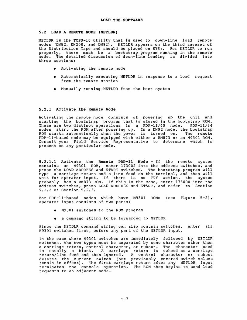
LOAD THE SOFTWARE
5.2 LOAD A REMOTE NODE (NETLDR)
NETLDR is the TOPS-IO utility that is used to down-line load remote nodes (DN82, DN200, and DN92). NET LOR appears on the third saveset of the Distribution Tape and should be placed on SYS:. For NETLDR to run properly, there must be a bootstrap program running in the remote node. The detailed discussion of down-line loading is divided into three sections:
• Activating the remote node
• Automatically executing NETLDR in response to a load request from the remote station
• Manually running NETLDR from the host system
5.2.1 Activate the Remote Node
Activating the remote node consists of powering up the unit and starting the bootstrap program that is stored in the bootstrap ROM. These are two distinct operations in a PDP-ll/40 node. PDP-ll/34 nodes start the ROM after powering up. In a DN92 node, the bootstrap ROM starts automatically when the power is turned on. The remote PDP-ll-based node may be equipped with either a 8M873 or an M9301 ROM. Consult your Field Service Representative to determine which is present on any particular node.
5.2.1.1 Activate the Remote PDP-ll Node - If the remote system contains an M9301 ROM, enter 173002 into the address switches, and press the LOAD ADDRESS and START switches. The bootstrap program will type a carriage return and a line feed on the terminal, and then will wait for operator input. If there is no TTY action, the system probably has a 8M873 ROM. If this is the case, enter 173000 into the address switches, press LOAD ADDRESS and START, and refer to Section 5.2.2 or Section 5.2.3.
For PDP-II-based nodes which have M9301 ROMs (see Figure 5-2), operator input consists of two parts:
• M930l switches to the ROM program
• a command string to be forwarded to NETLDR
Since the NETDLR command string can also contain switches, enter all M930l switches first, before any part of the NETLDR input.
In the case where M930l switches are immediately followed by NETLDR switches, the two types must be separated by some character other than a carriage return, control character, or rubout. The character used is usually a blank. A carriage return is echoed as a carriage return/line feed and then ignored. A control character or rubout deletes the current switch (but previously entered switch values remain in effect). The first carriage return after any NETLDR input terminates the console operation. The ROM then begins to send load requests to an adjacent node.
5-7

LOAD THE SOFTWARE
There are three M9301 switches:
/Lsyn#
/Nnn
/Sser
tells the ROM to transmit the load requests on line syn#. If either syn# or the entire switch is not present, the load requests are sent out on line O.
tells the ROM to designate node nn as the system (which must be a TOPS-IO host) to receive the load requests. In a multihost network, this switch will determine which host is to perform the down-line load. If the entire switch is not present, the node accepts loading from any host.
tells the ROM to override the default serial number in the load request with the number sere If either ser or the entire. switch is omitted, the serial number defaults to zero.
If you issue a carriage return in place of entering M9301 switches ~r a NETLDR command string, the load request will be the same as for a 8M873 node. It will specify a PDP-II node, serial number 0, and will be sent on line o. If line 0 is inoperable, the node will not be loaded.
However; the M9301 switches give you substantial flexibility regarding alternate load paths. In Figure 5-2, if line 0 on node THREE is inoperable, you can route the load request through node FOUR by specifying the M9301 switch:
/LI
Node FOUR converts the load request to a station control message, adds its own node name, adds the number of the synchronous line leading back to the node requesting the load, and then forwards the message to the host at node SIX. Also, node SIX can load node TWO and node ONE can load node FIVE.
16
Node ONE
14
TOPS-10 HOST
Node SIX
TOPS-10 HOST
17 Node TWO
DN87S
15 Node FIVE
DN87S
Figure 5-2: Loading an M9301-Equipped Remote Node
5-8
32
22 Node THREE
DN82
M9301
MR-S-821-80

LOAD THE SOFTWARE
If the network consists of more than one host, the /N switch allows you to specify the host that is to do the loading.
If the network contains multidrop nodes, you can use the M9301 switch /S to identify the node on the synchronous line that is requesting the load.
For example, the following operator input generates a load request. This request specifies that node 10 is to load the remote node with the program DIAGl.BIN:
/NIO DIAGl.BIN/LOAD
If the NETLDR command string is included, it has the following format:
filespec/switch/switch •••
where:
filespec is the dev:filename.ext[P,PN] designation of the file to be loaded into the remote node. If a filespec is specified, filename must be present. The rest of the filespec defaults to a .BIN file on your user disk area.
The optional NETLDR switches that are applicable in bootstrap messages are as follows:
/IMAGE
/LOAD
/PACKED
/START:addr
specifies that the file to be read is in image (unpacked) mode. This is the default mode for a PDP-8 node.
specifies that NETLDR is to load a file into the remote node but not start the program.
specifies that the file to be read is in packed mode (four 8-bit frames per TOPS-IO word). This is the default mode for a PDP-II node.
specifies that the program that was just loaded is to be started at address addr. If the command string did not include a filespec, NETLDR starts the program that is currently in memory. This switch is not necessary if filespec is present and if the program to be loaded is to start at its default start address.
If the remote station contains an M9312 ROM, the new M9312 ROM works like the old M9312 ROM, as outlined below:
1. Reliably boots DMCll interfaces connected to other DMCll interfaces (DMC can be read as DMR as well).
2. Has the following built-in error messages:
?DMC
?NXM
iAn error occurred in trying to use the DMCll. It can be generated by a user who may be plugging or unplugging the EIA or V35 interface cables while the ROM is running.
iThe ROM experienced a nonexistent memory trap. This indicates a definite hardware problem, such as a misaddressed DMCll or memory, or a broken memory.
5-9

?CHK
LOAD THE SOFTWARE
iThe ROM error checking code has detected a checksum error in the ROM itself. The checksum is of the sliding variety to detect ROM chips placed in wrong sockets.
The operation of the new M9312 is also the same as that of the old M9312, as follows:
1. Halt the PDP-ll/34.
2. Reset the PDP-ll/34.
3. Boot the PDP-ll/34.
4. The console types out an underline () prompt. Enter the desired load file's specification and any switches that are desired. Rubout or CTRL/U will kill the current line and it will have to be typed in from the beginning.
5. Press RETURN.
The 930lWB version of the M93l2 ROM has the capability of booting DMCll interfaces (as described above), but has no error messages because the DN20 does not have a console. The old M930lWB ROM only booted from the first configured DMCll. The new 930lWB ROM boots from DMC/DMRlls 0 through 7. The old and new ROMs are operated using the steps outlined below:
1. Halt the PDP-ll/34.
2. Reset the PDP-ll/34.
3. Enter the number of the DMC you wish to boot in the switch register.
4. Load the address 165002 into the address register.
5. Start the PDP-ll/34 with the start button.
5.2.1.2 Activate the Remote PDP-8 Node - If the remote node is a DN92, its ROM bootstrap program automatically begins execution when the station is turned on. As a network node that needs to be loaded, the DN92 sends a 'load request' over its synchronous line. The node that receives the request then transmits the request to the TOPS-IO host. Once the TOPS-IO host has received the request, it automatically runs NETLDR. (Unless the SCHED bit has been set to 1000. See Section 5.2.2.) NETLDR then loads the DN92 station.
You can use three switches with the DN92 ROM which are similar to those available for the M930l ROM. These switches are:
Switch
/Nnn
/Rd
/Sser
Meaning
Specifies node nn as the host to receive the load requests.
Specifies that program location d in remote value of 1 to 5 digits).
execution is to begin at station memory (d is an octal
Specifies the serial number to be sent in the load request as sere This is the serial number of the node to be loaded.
5-10
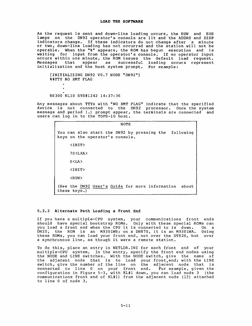
LOAD THE SOFTWARE
As the request is sent and down-line loading occurs, the RUN and BUS lamps on the DN92 operator's console are lit and the ADDRS and DISP indicators change. If these indicators do not change after a minute or two, down-line loading has not occurred and the station will not be operable. When the "%" appears, the ROM has begun execution and is waiting for input from the operator's console. If no operator input occurs within one minute, the ROM issues the default load request. Messages that appear as successful loading occurs represent initialization and the host system prompt. For example:
[INITIALIZING DN92 VO.7 NODE "DN92"] %%TTY NO XMT FLAG
RS300 KLIO SYS#1242 14:37:36
Any messages about TTYs with "NO XMT FLAG" indicate that the specified device is not connected to the DN92 processor. Once the system message and period (.) prompt appear, the terminals are connected and users can log in to the TOPS-IO host.
NOTE
You can also start the DN92 by pressing the following keys on the operator's console.
<IN IT>
70<LXA>
O<LA>
<INIT>
<RUN>
(See the DN92 User's Guide for more information about these keys:r-
5.2.2 Alternate Path Loading a Front End
If you have a multiple-CPU system, your communications front ends should have special bootstrap ROMs. Only with these special ROMs can you load a front end when the CPU it is connected to is down. On a DN20, the ROM is an M9301WBi on a DN87S, it is an M9301WA. Using these ROMs, you can load your front end, not over the DTE20, but over a synchronous line, as though it were a remote station.
To do this, place an entry in NETLDR.INI for each front end of your multiple-CPU system. In the entry, specify the front end nodes using the NODE and LINE switches. With the NODE switch, give the name of the adjacent node that is to load your front,endi with the LINE switch, give the number of the line on the adjacent node that is connected to line 0 on your front end. For example, given the configuration in Figure 5-3, with KL#l down, you can load node 3 (the communications front end of KL#l) from the adjacent node (12) attached to line 0 of node 3.
5-11

LOAD THE SOFTWARE
Node 3 Line 0
DTE
KL~ MR-S-820-80
Figure 5-3: Dual-Processor Nodes
An entry in NETLDR.INI (on KL#O) to load node 3 from node 12 over line 1 of node 12 will do the job. The entry in NETLDR.INI is in the following format:
filespec/CPUtype/NODE:nodeid/LINE:syn#
For example:
PDP-II is CPUtype /11 and PDP-8 is CPUtype /8.
For example:
DN2003/11/NODE:12/LINE:l
Once you place the entry in NETLDR.INI, start the M9301WA or M9301WB ROM. To start the ROM, enter 165002 at the start address and start the front end. The ROM then sends a boot request to the host system. This boot request activates NETLDR, which then reloads and starts your front end.
Both the M9301WA and M9301WB ROMs have an alternate starting address you can use to pass boot-request arguments to the ROM. You can use this alternate starting address to start a communications front end over a line other than line 0, or to start a communications front end directly from its programmer's console (not using a terminal). The alternate starting address is 165000. When you start the front,end at this address, the ROM reads register O. Register 0 points to a 4-word argument block of the following form:
.WORD SERIAL
• WORD NODE
.WORD LINE
.WORD 0
serial number of the local node you wish to start
node number of the host to receive the boot request
line over which you send the request
boot
either 0 or a pointer to an ASCIZ boot string (commonly 0)
5-12

LOAD THE SOFTWARE
This argument block is defined in the GO. ROM routine of the DNCOMM.Pll communications module. For example, assume you are standing at node 3 in Figure 5-3. Node 3 has serial number 70, and you wish to start it from KL#O (node number 20). Node 3 is connected over line 1 to an adjacent node attached to KL#O.
Enter 70 followed by 20 followed by 1 followed by 0 and start your DN20. Your node will be loaded from KL#O.
5.2.3 Invoke NETLDR Automatically
When a remote node is activated, the bootstrap program in the ROM sends load requests over one of its synchronous lines to an adjacent node (the adjacent node must be running). A load request contains the type and serial number of the node to be loaded and, optionally, the number of the host node to do the loading as well as a NETLDR command string.
The adjacent node converts the load request into an NCL station control message and then adds its node name and the number of the line that leads back to the node to be loaded. The station control message is then sent to the host processor. If SCHEDule bit 1000 is not set, the TOPS-IO host then automatically loads and runs the NETLDR program. The TOPS-IO operating system command, SET SCHED 1000, inhibits the automatic running of NETLDR.
If the original load request included a file specification, NETLDR loads that file into the specified node directly.
If NETLDR decides that the request does not contain sufficient information, it searches the SYS:NETLDR.INI file for an entry matching the load request information supplied.
Each entry in the NETLDR.INI file consists of two parts separated by an equal sign. The left half of each entry is of the form:
/NODE:nodeid/LINE:syn#/TYPE:type/SERIAL:ser
where:
/NODE:nodeid
/LINE:syn#
/TYPE:type
/SERIAL:ser
specifies the node name or node number of the node adjacent to the node to be loaded.
specifies the number of the synchronous line on the adjacent node that leads to the node to be loaded.
specifies the type and standard memory size of the node to be loaded. Use DN82 for DN80-series nodes. Use DN92 for DN92 stations.
specifies the serial number of the node to be loaded. This switch can be used if the remote node has an M9301 ROM or is a DN92 remote station (see Section 5.2.1.1 for an M9301 ROM, or Section 5.2.1.2 for a DN92). You can also use this switch with any value of ser when dumping PDP-II nodes.
If the contents of the left half contain less information than the load request, the system makes a match according to the information provided.
5-13

LOAD THE SOFTWARE
The right half of each entry is of the form:
=commandl,command2 •••
where:
command is a file specification and/or optional switches as described above.
Assume, for example, that the NETLDR.INI file at the host node SIX in Figure 5-2 contains the following entry:
/NODE:FOUR/LINE:l/TYPE:DN82=DN8222
A load request from node THREE, routed through node FOUR, would match on the above entry. NETLDR would then load the node connected to line 1 of node FOUR with the file SYS:DN8222.BIN. (For a load file, SYS: is the default device and .BIN is the default file extension.)
If there is no match in NETLDR.INI, the following message appears:
?NETNMI - Cannot find match in SYS:NETLDR.INI
In this case, correct the NETLDR.INI file.
In a multihost network, any host may receive the load request sent by a 8M873 ROM (or an M9301 ROM started at 173000). If the host receiving the request does not have access to the appropriate load file, the node will not be loaded. You can provide for host discrimination with specific switches to NETLDR.
For the automatic down-line loading of any DN92 node, SYS:NETLDR.INI must contain a line of the following form:
/TYPE:DN92=DN9224.BIN
If the software has a name other than DN9224.BIN, that name should be used; if the softwar~ is not on SYS:, the [P,PN] of the appropriate area must be added to the file specification. For example, the following line in NETLDR.INI specifies that any DN92 node that sends a load request to NETLDR will be loaded with the file DN9224.BIN:
/TYPE:DN92=DN9224.BIN
To get an automatic up-line dump of the remote station before down-line loading, insert a /DUMP switch before the command file specification. For example, the following line in NETLDR.INI will up-line dump memory of any DN92 remote node onto the user's area on the TOPS-IO host:
/TYPE:DN92=/DUMP,DN9224.BIN
The dumped file is called nodename.LSD. You can also use DN92??BIN (or the equivalent for other nodes) in NETLDR.INI to capture dumps for all DN92 nodes with any node number. You can get unique file names for each dump file by typing this command:
/DUMP:DN9224.D??
If a host is to disregard all load requests, the system operator can inhibit the running of NETLDR by typing the operator-privileged command:
.SET SCHED 1000
5-14

LOAD THE SOFTWARE
If, however, only requests from certain nodes are to be disregarded, uSe the NETLDR switch, /IGNORE, in NETLDR.INI file entries. For example:
/NODE:NODED/LINE:I=/IGNORE
will disregard all requests to load a node connected to line I of node NODED.
/NODE:NODED=/IGNORE
will disregard all requests to load any node connected to node NODED.
5.2.4 Operator Use of NETLDR
The NETLDR program can be run from the host node to dump, load, and execute programs in a remote node. A dump can be taken of a running node, but a node can only be loaded if it has sent an up-line load request to the host. Load the NETLDR program:
.R NETLDR~
NETLDR prompts you with:
FILE:
NETLDR expects you to reply to the prompt with a command string of the form:
FILE:filespec/CPUtype/NODE:nodeid/LINE:syn#/switch/switch •••
or
FILE:filespec/CPUtype/NODE:nodeid/SELF/switch/switch •••
where:
filespec
/CPUtype
/NODE:nodeid
/LINE:syn#
is of the form dev:filename.ext[P,PN]. If this is a load operation, filename is required. The other arguments default to a .BIN file on your user disk area. If this is a dump operation, the entire file specification can be omitted and will default to nodename.LSD on your disk area.
is a required switch that specifies the type of processor at the remote node. For DN80-series nodes, enter /PDPll or /11. For a DN92 remote station, enter /PDP8 or /8.
is a required switch used to sp~cify the node to be operated on. The switch value, nodeid, can be either a node name or a node number. If the remote node is running, nodeid identifies the node itself. If the remote node is not running, the usual case in a load operation, nodeid identifies an adjacent node that is running.
is a required switch when performing a dump or load operation on a node that is not running. This entry identifies the line that leads from the node to be operated on to an adjacent running node.
5-15

/SELF
LOAD THE SOFTWARE
is a required switch (if the /LINE switch is not used) when performing a dump operation on a node that is running. This entry specifies that the dump is to be performed on the node specified by the /NODE switch.
The following NETLDR switches are optional as some apply to load operations and others to dump operations.
/DUMP
/DUMP:c-d
/DUMP:c-*
/HELP
/HPQ:n
/IMAGE
/LOAD
/PACKED
/START:addr
creates a full memory octal dump of the node specified by the /NODE switch.
creates an octal dump from address c to address d.
creates an octal dump from address c to the largest address of the processor.
NOTE
You can have NETLDR create successive dump files of the same name (the default is that NETLDR overwrites the old version) by including a question mark (?) as a character in the file name each time you request a dump. NETLDR replaces the question mark with 0 the first time you use this format. Each time thereafter, when you specify that file name, NETLDR creates a new dump file and replaces the question mark with an increment of 1.
If you do not specify a dump file specification in the command string, the default filespec is nodename.LSD on DSK:.
outputs the NETLDR help file.
specifies the high priority queue number. To have the running of NETLDR take precedence over other timesharing jobs, set HPQ=l or some higher number. This switch can only be used if you have HPQ privileges and if the number of high priority queues in the system is nonzero.
specifies that the file to be read is in image (unpacked) mode. This is the default mode for a PDP-8 node.
specifies that NETLDR is to load a file into the remote node but not start the program.
specifies that the file to be read is in packed mode (four 8-bit frames per TOPS-IO word). This is the default mode for a PDP-II node.
specifies that the program just loaded is to be started at address addr. If the command string does not include a filespec, NETLDR starts the program that is currently in memory. This switch is not necessary if filespec is present and the program to be loaded is to start at its default start address.
5-16

LOAD THE SOFTWARE
5.2.5 Examples
To load the file NYC.BIN from DSKN: area [14,16] on the host node into the node connected to line 0 of node BOSTON and start the program at address 1000, issue the following string to NETLDR in response to the "FILE:" prompt:
DSKN:NYC[14,16]/NO:BOSTON/LI:0/11/START:1000
To dump locations 0 to 77776 of node BOSTON onto DSK: as a file named BOSTON. LSD, issue the following string to NETLDR in response to the "FILE:" prompt:
FILE: /DUMP/NODE:BOSTON/SELF/PDP11
5-17


CHAPTER 6
INITIAL HARDWARE CHECR
As a node is loaded and started, a program runs to make a cursory check of the hardware. CHKll runs in a PDP-II-based node, and SYSCHK, an integral part of DN92 code, runs in a PDP-8-based node.
6.1 INITIAL HARDWARE CHECK (CRRII) POR PDP-II-BASED NODES
The last source module assembled into the node's software in Chapter 4 was CHKll.Pll. CHKll is a hardware test module for PDP-II-based nodes and is brought in and started whenever a node is loaded. CHKll runs hardware diagnostics on the node's memory and devices to see that they are functioning correctly. The names and quantities (in octal) of each device type are printed on the system's console terminal if one is present. Representative CHKll output for a successful load of a DN20 front end at node 65 could be:
Initializing DN20 V23(203) MAR 1983 - NEXT (27)
160000 bytes of memory MFII-UP KWII-L
1 DLII-A 1 DTE20 1 KMCII-DUP 2 DUPll's 1 KMCII-DZ 1 DMCll 4 DZll's
Restarting DN20 V23(203) MAR 1983 - NEXT(27)
NOTE
When CHKll runs, it displays the ASCII character set twice on all terminals set to a speed of 9600 baud and connected to the node. This appears as random data on all terminals not set to 9600 baud or connected to the node with DZll lines.
6-1

INITIAL HARDWARE CHECK
If a problem is detected by CHKll, the error information is printed in the following format:
? devnam#devnum(ADR=devaddr) ERROR AT srcaddr
(message describing problem) REG/ADR=addr GD=expval BD=actval XOR=varbits [FATAL ERROR]
where:
devnam
devnum
devaddr
srcaddr
addr
expval
actval
varbits
is the device name.
is the device number. Device numbers are sequential, starting with O.
is the first address of the device.
is the address in the source listing where you should look for this error.
is the actual address in memory where the error occurred.
is the expected value in addr.
is the actual value in addr.
are the bits resulting from the EXCLUSIVE OR operation on the expected and actual values.
The message FATAL ERROR is printed if the error is such that CHKll is unable to continue (memory errors or KWll clock errors). When CHKII stops on a fatal error, a stop code is displayed in the console data lights. Table 6-1 lists the error stop codes and their meanings.
Table 6-1: CHRll Error Stop Codes
Stop Code Meaning
1 Timeout or bus error (trap to address 4)
2 DLIO error
5 No console terminal
6 Memory error
7 KWII clock error
For additional information about CHKII and a complete list of CHKII error messages, refer to TOPS-IO CHKII Reference Manual.
6-2

INITIAL HARDWARE CHECK
6.2 INITIAL HARDWARE CHECK (SYSCHK) FOR THE DN92
When the DN92 is down-line loaded by NETLDR, SYSCHK is executed. SYSCHK performs a check of the DN92 hardware and issues messages at the DN92 operator's console.
NOTE
SYSCHK is not executed when the DN92 is restarted manually.
SYSCHK execution takes about preceded by either %% or meaning) •
a minute. ?? (these
A SYSCHK message may be characters have no special
All of the messages output by SYSCHK or the DN92 code are listed in Table 6-2. With the exception of the first, which is always seen when the station has been successfully loaded, all messages are in alphabetical prder, ignoring the % or? characters. 'DP8E' refers to the synchronous line interface modem controller. Generally, if these DP8E messages appear, you should contact Digital Field Service.
Table 6-2: DN92 Software Messages
Message
[INITIALIZING DN92 VI.INODE "name"]
BAD MESSAGE TYPE
CARRIER BACK
CARRIER LOST
DKC8 CLOCK ERROR
DN92 CRASH PC=IIIII
DN92 INT ERR
Meaning
SYSCHK has begun. 1.1 contains the version number of the DN92 software; "name" is the nodename specified in the configuration file.
The DN92 received a message in an invalid format from the TOPS-IO host.
The carrier from the synchronous modem has returned.
The carrier from the synchronous modem has been lost.
A fatal error. SYSCHK measured the speed of the DKC8 line frequency clock and found it either too fast or too slow. The clock may be malfunctioning or not present, or the processor speed may be incorrect.
A fatal error detected by software. The ROM is automatically restarted and issues a default load request after one minute. The DN92 operator can dump core by starting the dump program at location 201.
A hardware problem in the DN92 or an incorrect definition of the configuration at assembly time.
DN92 WON'T RUN ON A PDP8-I DN92 software cannot run on a PDP8-I (SYSCHK looks for a BSW instruction).
6-3

INITIAL HARDWARE CHECK
Table 6-2: DN92 Software Messages (Cont.)
Message Meaning
~.-------------------------------~--------------------------------------------
DP8E BUS ERROR
DP8E CHAR DETECT SKIP FAILED
DP8E FIELD SELECT FAILED
DP8E FLAG WON'T CLEAR
DP8E GT 9600 BAUD
DP8E IS IN LOOPBACK MODE
DP8E MODEM NOT READY
DP8E NO CARRIER
DP8E NOT CLEAR TO SEND
DP8E NOT RECEIVING
DP8E RCVD #
DP8E READ CHAR DETECTED # RIGHT 3
A receive or transmit bus request was not serviced within one baud; either the receive or the transmit modem clock is faulty.
A hardware problem SYSCHK (SYSCHK character from special character up) •
in DP8E detected by received a sync
the DP8E, but the flag did not come
Either DP8E is not installed or there is a serious hardware failure; contact Field Service.
SYSCHK cannot clear a flag in the DP8E.
SYSCHK found the synchronous speed greater than 9600 Throughput may be degraded synchronous links faster than baud.
line baud.
with 9600
SYSCHK sent a pattern out on the synchronous line but it came back. A modem on the line is probably in loopback mode; reset it and either reload or restart the program at PC 200.
Be sure the modem on the synchronous line is powered on and ready (SYSCHK READ STATUS I instruction).
SYSCHK attempted to initialize the DP8E but the READ STATUS 2 instruction indicates that CARRIER/AGC is not present. Verify that modems are ready and sending and that the link between the modems is working.
The modem may be off or not ready.
The synchronous line interface and modem are ready but are receiving no characters.
A non-SYNC character was received from the synchronous line. SYSCHK loops until it receives a SYNC character.
A problem in DP8E hardware. (SYSCHK expects a 3, but received an unexpected character (#) after the SYNC character.)
6-4

INITIAL HARDWARE CHECK
Table 6-2: DN92 Software Messages (Conto)
Message Meaning
DP8E TERM NOT READY A problem in DP8E hardware (SYSCHK set terminal ready, executed a DP8E READ STATUS 2 instruction, and found terminal ready not set).
DP8E WC OR CA WRONG A problem in DP8E hardware (SYSCHK found incorrect values in data-break reg i s t e r s) ..
DP8E XMT NOT READY A problem at the modem or between the modem and DP8E; the clock may not be received from the modem correctly (SYSCHK's attempt to send several SYNC's failed to complete quickly).
LPT FLAG WON'T CLEAR A hardware problem in the line printer interface (SYSCHK could not clear the line printer flag).
LPTTRBL The line printer has timed out and the FTTRBL flag has been set in the configuration file.
RESTARTING DN92 NODE":!t:!t:!t:!t" This message appears on all DN92 TTYs whenever the station is restarted manually; #:!t:!t:!t indicates the node name defined in the configuration file (default = DN92) •
RDCHK-REFEED CARD A card-reader error in reading a card. Read the card in again.
TTY NOT CONNECTED This message can appear on any TTY; it indicates that the terminal is not connected to a host. It generally indicates a problem at an intermediate node or a crash of the TOPS-IO host. This message also appears when a connection is broken. If the DN92 receives input from an unconnected TTY, it sends a connect request to the host node.
TTY:!t IS RUNNING OPEN The interface to TTY:!t (:!t is the line number) is receiving a continuous stream of null characters. This condition is not fatal but will overload the station if the stream is running faster than 110 baud.
TTY:!t NO XMT FLAG The indicated line :!t does not exist.
TTY:!t RCV FLAG WON'T CLEAR
TTY:!t XMT FLAG WON'T CLEAR
If the line is part of the installation, contact Field Service.
A fatal hardware error; contact Field Service.
A hardware problem; contact Service.
6-5
Field


APPENDIX A
CONFIGURATION FILE SWITCHES
Entries that can be made in the configuration file are listed in Table A-I in alphabetical order. Each entry in the configuration file must be in the form:
ENTRY=value
Spaces are allowed, except in character strings like nodename. Switches listed in this appendix that are not included in Table 3-1 are used only for debugging. Some switches apply only to certain node types. The definitive list of switches for the node for which you are assembling software can be found in the .LST listing created at assembly time. (For example, when assembling software for a DN92 remote station, all switches with their set values are listed at the end of the .LST listing.) The value given for each switch in Table A-I is a typical value. Most values are either 0 or 1; values greater than 1 are expressed in octal.
Table A-I: Configuration File Switches
Switch Description
ABRGM=O If nonzero, optimizes the text storage area for DGUTS error message (default = 0). This switch applies only to PDP-II based nodes.
CDRN=l
CNKFLD=l
CNKSIZ=lOO
CP.SIZ=xx
CTRLN=2
CTYWID=110
The number of card readers at the remote station (0 or 1 only).
The memory field which contains chunks (0 for the first field, 1 for second, 2 for third). This switch only applies to DN92 nodes.
The size of the memory chunk; the range is 4 to 200. This value must be a power ,of 2 (default is 100 words = 144 octal).
Defines the buffer size (in bytes) for the POKE debugging aid. The POKE aid is disabled if this buffer is not defined.
The number of controllers using DDCMP.
The width of a hardcopy terminal or CTY at the remote station (default = 72 characters = 110 octal) •
A-I

CONFIGURATION FILE SWITCHES
Table A-I: Configuration File Switches (Cont.)
Switch Description
DEBUG=l Enables debugg ing features. (If 0, 1 i ttle or no consistency checking is done; if 1, some checking occurs and reloads are done on serious errors; if -1, reloads occur on all errors.)
DEFBCD=bll.
DELROM=l
DGUTS=O
DHCn=O
DHLn=O
DHSn=B.s
DIDLLS=l
DLIOSR=164000
The default type ball for IBM 2741 terminals:
938.=BCD 963.=EBCDIC 987.=APL correspondence 988.=APL (EBCDIC)
If 1, overrides ROM restart at the remote station when the host processor crashes (default = 0) • Applies only to a DN92.
If 1, causes the remote station to attempt error recovery (default = 0). If defined, FT.CHK=O, FTASRT=O, and DEBUG=O; that is, these features are disabled.
If 1, specifies that DHll line n has modem control (default =0).
Specifies how DHll line n is used, as follows:
0 = (default) 1 = terminal line 2 = po in t-to-po int DDCMP line 3 = mul ti po int master line 4 = multipoint tributary line 5 = po in t-to-po in t DDCMP Remote Data Entry
line 6 = ASCII Remote Data Entry line 7 = line is not used
Specifies the transmit-and-receive speed for DHll line n. For example, DHSO=B.300 where DHll line o has a transmit-and-receive speed of 300 baud.
If defined, generates the code to setting of DHll line parameters Three symbols are defined·:
Location Contents
DHll hardware address. Line number from DHll.
permit the wi th DDTll.
DHHLC DHHLN DHHLO Parameter word (value for DHll line
parameter register).
(When the hardware address is assigned to DHHLC, the parameters are set and DHHLC is reset to zero.)
Allows CHKll to find a DLIO on a DN87 with 32K-word memory upgrade.
A-2

CONFIGURATION FILE SWITCHES
Table A-I: Configuration File Switches (Cont.)
Switch Description
DMCN=n The number of DMClls/DMRlls on a DN20 or DN200.
DMPHDR=l If 1, DDCMP message headers can be selectively dumped into a circular buffer. The buffer is the size of a DMPHDR header (8 times the number of DMPHDR bytes) •
DMPHIN=value
DMPHLN=addr
DMPHOU=O
DMPMSG=O
DNllN=O
DUPN=n
DZCn=O
DZLn=O
DZSn=B.s
FT.ANF=O
FT.BIG=l
FT.CHK=O
FT.CTY=l
FT.DDT=O
FT.DTE=O
FT.HLP=l
If DMPHDR is defined, number of incoming (default = DMPHDR).
DMPHIN can specify the DDCMP headers to record
If DMPHDR is defined, DMPHLN gives the address of the 'line block' for the DDCMP line.
The number of outgoing DDCMP headers to record if DMPHDR is defined (default = 0).
Enables selective dumping of data messages on a DDCMP line. (This feature requires the FT.SNK sink debugging aid to be nonzero.)
The number of DNll dial-out units at a remote station.
Gives the number of DUPlls on a DN20 or DN200.
If 1, specifies that DZll line n has modem control (default=O).
Specifies how DZll line n is used (default=O). The values of DZLn are the same as those shown for DHLn.
Specifies the transmit-and-receive speed for DZll line n. For example, DZSO=B.2400 where DZll line o has a transmit-and-receive speed of 2400 baud.
If 1, causes the inclusion of code to support image mode in task-to-task communications (default = 1).
If 1, causes additional code to be used for improving error reporting and line control (default=l) •
If 1, uses the code for consistency checking and enables TWIDDL macros; always 0 if DGUTS=l.
If 1, allows a hardcopy terminal on DLII to be used as a TTY (default = 0 on DC75NP, DN85, DN20; default = I or 3 on all others).
If 1, leaves room for PDP-II DDT.
If 1, DTE-20 support is needed (for example, for a DN20 or a DN87S).
If 1, allows debugging messages to be sent to the remote station CTY (default = 0) •
A-3

CONFIGURATION FILE SWITCHES
Table A-I: Configuration File Switches (Cont.)
Switch Description
FT.MPT=O If 1, supports multidrop lines. (In this case, DNCDDH.Pll and DNRDE.Pll must be in the program list for MACDLX and the value for FT.DCP must be O. )
FT.PFH=l If 1, enables the preferred-host feature (default = 0) •
FT.PFL=O If 1, enables the 'profiler' feature, which samples the PC register and creates an in-core histogram of program activity (default = 0).
FT.QSB=l
FT.RDA=l
FT.RDE=l
FT.RNN=l
FT.ROM=l
FT. SLB=l
FT.SNK=O
FT.SOU=O
FT.STC=l
FT.TSK=O
FT.typ
If 1, implements QSYNC bit This entry is required operation when using TOPS-IO later, and is now the default.
in DCMP protocol. for correct DDCMP
Version 6.03 or
If 1, generates the code to support ASCII remote data entry devices.
If 1, supports multidrop remote data devices on the network.
entry
If 1, supports restricted devices. This switch must be 1 if TnnRNN=nodenum is used.
If 1, supports certain remote bootstrap ROMs. (This switch remote stations not attached processor by a OLIO or a DTE20.)
stations must be to the
with 1 for host
If 0, omits all of the debugging information from the line blocks. This switch should always be 1 (default = 1).
If 1, enables SINK debugging macros (default = 0) • To set this to 1, you must use DNDBG.Pll. Use this only during debugging.
If 1, enables the 'message source' feature, which permits the single or periodic insertion of predefined messages into the operating code (default = 0). To set this to 1, you must use DNDBG.Pll. Use this only during debugging.
If 1, DDTll can be used to do remote examines/deposits of PDP-II memory (default = 1) •
If 1, special purpose user-supplied tasks (for example, multiprocessing) can be scheduled within the node.
The value of this switch declares the node type and includes the code for that type of node at assembly time. Allowable node types are: 020, 200, 075, DBO, OBI, DB2, DB5, DB7, and B7S.
L-________________ ~L-__________________________________________________________ _
A-4

CONFIGURATION FILE SWITCHES
Table A-I: Configuration File Switches (Cont.)
Switch Description
FT2BIT=1 If 1, sets the minimum length of the stop bit for certain terminal lines at 2. This switch should be 1 for terminal lines operating at 300 baud or faster.
FT3.02=1
FTB73=1
FT2741=0
FTAPTH=l
FTASRT=l
FTBSTC=O
FTCLEA=O
FTDLIO=O
FTDHll=O
FTDMll=O
FTDN 11=0
FTDPll=O
FTDMCll=O
FTDQll=O
FTDZll=O
FTDUPll=O
If 1, the code is compatible with DDCMP 3.02 and 4.0. This switch must be operation with TOPS-IO Version 6.03 or (default is 1).
If 1, the BMB73 bootstrap ROM is present.
If 1, supports IBM 274ls.
Version o for later
Enables alternate paths for NCL logic (default is 1) •
If 1, enables the ASSERT macro.
If 1, includes the code for automatic bootstrapping of remote stations with ROMs.
If 1, core is cleared before a start or restart is run (always 0).
If 1, DLIO interfaces can be used. This switch should be 1 for a DN75, DNB5, or DNB7.
If 1, DHll asynchronous line controllers can be used. This switch should be 1 if any TTYs are present on a DNB7, DNB7S, DNB1, or DNB2 (defaults to 1 when there are TTYs on a DNBx-node) •
If 1, DMllBB modem controllers can be used. If any TTY lines are dataset lines on a DNB7, DNB7S, DNB1, or DNB2, this switch must be 1.
If 1, uses the DNll code.
If 1, uses the code for the DPll synchronous line controller. Applies only to DC75NPs.
If 1, uses the DMCll code.
If 1, uses the code for the DQll NPR synchronous line interface. This switch must be specified for a DNB2, DNB5, DNB7, or DNB7S, except asynchronous (only DNB7 and DNB7S). Defaults to 1 if NLINES is greater than 0 in a DNBx-node.
If 1, the code for the DZll asynchronous line controllers can be used. This switch should be 1 for a DN20 supporting TTYs. Defaults to 1 if TTYN is greater than zero for a DN2x-node.
If 1, uses the code for the DUPll synchronous line interface.
A-5

CONFIGURATION FILE SWITCHES
Table A-I: Configuration File Switches (Cont.)
Switch Description
FTDS11=0 If 1, uses the code for the DS11. This switch must be 1 for a DC75NP and only applies to a DC75NP.
FTDU11=0 Always O.
FTEVEN=O
FTExxx=l
FTHOST=O
FTKG 11=1
FTLBAC=O
FTLPLC=O
FTLPl1=0
FTLP20=0
FTNSYN=nn
FTOLDC=O
FTQSYN=nn
FTRACE=O
FTSILO=32.
FTSLCT=O
FTSTCD=l
FTTWID=O
JIFSEC=60.
If 1, messages are padded in order to end on an even word boundary.
If 1, supports the specified IBM 2741 type ball. The variable xxx can be 938, 963, 987 or 988. The default is 988.
If 1, supports the SET HOST command. Default is 1.
If 1, does not support KG11 devices that compute CRCs and LRCs (default is 1).
If 1, a loopback test can be used (default is 0).
If 1, the lowercase. DN92 nodes.
LA180 This
line printer can output in switch is applicable only to
If 1, supports the LPll line printer.
If 1, supports the LP20 line printer.
The number of SYN characters sent before a DDCMP control message (must be even and greater than or equal to 2; default = 8).
Must be 0 for TOPS-10 Version 6.03 and later.
The number of SYN characters sent after a message (must be even and greater than or equal to 2; default = 2).
Used as a debugging tool; causes TRACE macros in the network software to be expanded.
Sets the DHI1 silo alarm level; must be less than 64 and a power of 2.
Determines the selection algorithm for multidrop lines; default is O.
Must be I for any remote station debugging. If 1, a user with POKE privileges can deposit in remote memory with DDTII (default is 1).
If 1, expands TWDDL macros. used for debugging.
These macros are
The number of jiffies in one second; always 60 for a 60 Hz PDP-II remote station, 50 for a 50 Hz station (default is 60. (decimal».
A-6

CONFIGURATION FILE SWITCHES
Table A-I: Configuration File Switches (Cont.)
Switch Description
LA180=1
LPTFAK=O
LPTN=O
LPTWID=204
MAXOLN=244
NCL. LG=O
NLINES= sy
NUMSYN=lO
QURNNM=nn
PDPll=mn
PEEKDM=O
PRFL.L=bound
If 1, enables LA180s. This switch is applicable only to DN92 nodes.
If 1, discards LPT output (default is 0).
If 1, supports a line printer at the remote station.
The width of a line printer at a remote station (80 columns = 120 octal; 120=170 octal; 132=204 octal) •
The maximum output message size, in bytes.
If FTRACE is nonzero, NCL trace is enabled, as follows:
If Action
o Default (no action). 1 Traces all messages routed by the node. 2 Traces only device-control messages
destined for the node. 3 Equivalent to both 1 and 2.
If this switch is nonzero, symbols BUGBF and BUGQ are defined. BUGBF points to the 64-times-IO-word circular buffer for the trace. BUGQ is one word containing the address of the next entry in the trace. (Each 10-word entry in the buffer contains the top three words of the stack, the message length, and the first 12 bytes of the message. Generally, the top three words of the stack indicate the origin of the message.)
The number of synchronous lines attached to the node. If omitted, the default = 4. For a DN20, DN87, and DN87S with only asynchrnous lines, sy must always be 0; sy can be up to 12 with a DN20, DN200, DN87, and DN87S.
The number of SYN characters at the start of message.
Our node number. This can be 01 to 77 (octal) and must be unique within the network.
The model number of the PDP-II processor at the node. For example, mn must be 40 for DN8x, 15 for DC75NP, 34 for DN20 and DN200.
If 1, enables a facility to monitor modem-control state transitions on a DHll/DMll line (default = 0) •
Defines a low-boundary value for the profiler histogram (default = 1000 (octal».
A-7

CONFIGURATION FILE SWITCHES
Table A-I: Configuration File Switches (Cont.)
Switch Description
PRFL.H=bound
PRFL.S=power
REPDWN=36
REPSEC=2
REPTIM=170
RPLPOL=l
SCBMAX=mx
SDELAY=l
SLSDMP=O
TnDSL=l
TnRNN=nn
TnPFH=nn
TnRS=s
TnTAB=O
Defines a high-boundary value for the profiler histogram (default = 60000 (octal».
Defines the resolution of the prafiler histogram. Each bar has a width of 2 to the PRFL.S power (default = a; that is, 2 to the 8th power = 256) •
The number of DDCMP unanswered <REP> messages that must pass before the line is considered down.
The number of seconds between transmissions on an idle line.
DDCMP <REP>
RET timeout in jiffies (120 jiffies = 170 octal = 2 seconds).
If nonzero, enables remotely operated line printers to send messages to the CTY when they need assistance (default = 1).
The number of nodes the network can support. Must be greater than or equal to 2 since it includes the host processor (TOPS-IO) and the node being installed. This defaults to NLINES*2 for 20 and aO-series nodes; to NLINES for DC75NP.
A delay in seconds, defaults to O.
If 1, enables a facility to monitor synchronous line driver activity. If used, two buffers of SLSDMP words are defined; one is for the receiver, one for the transmitter (default is 0).
Specifies that line n is a dataset line (connects to a TTY using a modem). One such entry is required for each dataset line.
Defines a restricted terminal. The node number (nn) specifies which node is the default host for the specified TTY. This can only be used if FT.RNN=l.
Defines a preferred host. The node number (nn) specifies which host the TTY will be connected to, if the host is available. This feature can only be used if FT.PFH=l.
The receive speed for an asynchronous 1 ine wi th no autobaud detect. This switch should be used in conjunction with the TnnXS switch. Receive speed is the speed from the terminal to the node processor. Terminals on DZll lines must have the same transmit and receive speeds.
If 1, the terminal on line n has hardware tabs.
A-a

CONFIGURATION FILE SWITCHES
Table A-I: Configuration File Switches (Cont.)
Switch Description
TnWID=w Sets the width of the terminal connected to line n. Terminals specified with this switch must be attached through DHll interfaces. The default width is 72 characters (110 octal); allowable widths are 80 (120 octal) and 132 (204 octal). Maximum width is 255.
Tn80l=m Sets DNll number m for TTY n.
TnXS=s The transmit speed for a line with no autobaud detect. This switch should be used in conjunction with the TnRS switch. Transmit speed is the speed from the node processor to the terminal. Terminals on D2ll lines must have the same transmit and receive speeds.
TTYMIC=120
TTYN=#as
The maximum number of characters that can be typed in an input message from a TTY.
The number of terminals that can be connected, excluding the CTY. For DN87 and DN87S nodes, the number of terminals can be 16 times the number of DHll asynchronous line interfaces that are supported; for DN20 nodes, the number of terminals can be 8 times the number of D211 asynchronous line interfaces.
A-9


-A-
Abbreviations, vii Advanced Network Functions
see ANF-IO network ANF-IO network, 1-1, 5-2 Assemble software
automatically, 4-11 example, 4-4, 4-5, 4-6 for PDP-II-based processors,
4-2 for PDP-8-based processors,
4-10 Assembler
MACDLX, 2-1 PALlO, 2-1
Assembly modules for PDP-II-based processors,
4-1 inclusion of optional, 4-1 list of, 4-2
Asynchronous line, 3-13 Asynchronous line entry, 3-5
-8-
BACKUP program, 1-6, 2-5 command sequence, 2-5 prompt, 2-5
BM8 7 3 ROM, 5-7 start address, 5-7
BOOTll program, 1-6, 5-1, 5-2 exiting, 5-3 messages, 5-3 prompt, 5-2 response, 5-2
example, 5-3 start, 5-2
Bootstrap program, 5-7 Bootstrap ROM, 5-7, 5-11
-C-
Check program size, 4-3 CHKll program, 5-1, 6-1
error information, 6-2 error stop codes, 6-2 representative output, 6-1
Code, unsupported, 2-4 Communications front end
see Front end
INDEX
Communications node characteristics of, 1-4
Communications processors see Front end
Configuration ANF-IO network, 5-2
Configuration file, 3-1 asynchronous line entries, 3-5 DN92, .3-10 DN92 defaults, 3-11 entries for, 3-1, 3-2, 3-3 e x am pI e, 3 - 2, 3 -1 4 , 3 -1 5 , 3 -1 6 ,
3-17 global terminal entries, 3-7 macro default entries, 3-3 node-specific, 3-1 optional global entries, 3-8 PDP-II entries, 3-4 saving, 3-14 switches for, A-I to A-9 terminal entries, 3-5 values for entries, 3-1
Control files entries for, 3-1
Copy proced ure software, 2-5
CREF program, 1-6, 4-10 CUSP tape, 1-7, 2-5
-D-
DCP (DECnet Compatible Port), 1-1, 3-11
mod ul es, 2-3 DDTll files, 2-4 DDTll program, 1-6, 1-7
to save symbols, 4-7 DECnet Compatible Port
see DCP DECnet-lO, 1-1 DHll lines
define attributes of, 3-12 DHCNFG macro, 3-12
e x am pIe, 3 -1 3 DHUSE macro, 3-13
example, 3-14 Distribution Tape, 1-7, 2-1, 2-5,
3-·1, 4-10, 5-7 DN92
Index-l
configuration defaults, 3-11 configuration file, 3-10
DN92 (Cont.) control file, 4-11 modules, 2-4
see also PDP-8 modules node
down-line load, 5-14 entries for, 3-10
operator's console, 5-11 ROM, 5-10
switches, 5-10 software messages, 6-3, 6-4,
6-5 Documents referenced
list of, vi Down-line loading, 5-1, 5-7 DTELDR program, 1-6, 5-1, 5-2,
5-3 action switches, 5-4 modification switches, 5-4 prompt, 5-3 response, 5-3 star t, 5-3
DZll lines define attributes of, 3-12
-E-
Entr ies asynchronous line, 3-5 configuration file, 3-2, 3-3 DN92, 3-10 global, 3-7, 3-8 PDP-II, 3-4 synchronous line, 3-5 terminal, 3-5
-F-
Files DDTll, 2-4 supplementary, 2-4
Front end, 1-3, 5-11 automatic
load, 5-5 reload, 5-5
load, 5-11 starting, 5-12
-G-
Global entries optional, 3-8 special, 3-8 to define terminals, 3-7
-I-
INITIA program, 1-2 Initial system output, 1-7, 6-1,
6-3 Installation summary, 1-7
-K-
KDPLDR program, 1-3, 1-6, 5-5 functions of, 5-5 switches, 5-5, 5-6
examples of, 5-6
-L-
Lines communications, 1-1
Load automatic, 5-5 front end, 5-11 KMCll, 5-5 local nooe, 5-1, 5-2 over a OLIO, 5-2 procedures, 1-7 through a DTE20, 5-3
Load request, 5-8, 5-13, 5-14 dis reg a r d, 5 -1 4
-M--
M9301 ROM, 5-7 operator input for, 5-7 start address, 5-7 switches, 5-7, 5-8
M9301WA ROM start address, 5-12
al terna te, 5-12 M9301WB ROM
start address, 5-12 alternate, 5-12
M9312 ROM operation, 5-9, 5-10 9301WBversion, 5-10
MACDLX assembler, 2-1, 4-1 MACDLX program, 1-6, 3-1
command string, 4-2 Macro
Index-2
configuration-defining, 3-11 defaults, 3-3 DHCNFG, 3-12 DHUSE, 3-13 NSPLST, 3-11 TDEF, 3-12

Modules assembly, 4-1, 4-2 DCP, 2-3 DN92, 2-4 PDP-11, 2-1, 2-2, 2-3 PDP-8, 2-4
MaNGEN program, 1-1, 1-2, 1-3 Monitor creation
see MaNGEN program
-N-
NETLDR program, 1-6, 5-7, 5-12 command string, 5-9 example, 5-17 invoke automatically, 5-13 load, 5-15 NETLDR.INI file, 5-13, 5-14 prompt, 5-15 reply, 5-15 switches, 5-7, 5-9, 5-16
Network configurations, 1-4 see also Topologies ANF-10, 1-4 mu1 ti 1 ink, 1-5
Network programs list of, 1-7
Node, 1-1 dual-processor, 5-12 dump of, 2-3 local, 5-1, 5-2 maximum number of, 1-1 testing of, 2-3
Node name, 1-1 Node number, 1-1 Notation
see Abbreviations NSPLST macro, 3-11
-P-
PALlO assembler, 2-1, 4-1, 4-10 PALlO program, 1-6
example, 4-10 PDP-II code, 4-1 PDP-II modules
debugg ing, 2-3 device drivers, 2-2 miscellaneous, 2-3 order of assembly, 2-1 required, 2-1
PDP-II nodes required entries, 3-4
PDP-8 code, 4-1
PDP-8 modules, 2-4 see also. DN92, modules
Program size, 4-3
-R-
REACT program, 1-3 Reload, automatic, 5-5 Remote node
activate, 5-7 PDP-II, 5-7 PDP-8, 5-10
down-line load, 5-7 see also NETLDR program
load, 5-1 M9301 ROM-equipped, 5-8
Remote station, 1-3 characteristics, 1-3 up-I ine dump
automatic, 5-14 ROM bootstrap program, 5-10
-5-
Saving symbols, 4-7 example, 4-7, 4-8, 4-9
Source code, 1-7 Supplementary files, 2-4
1 i st 0 f, 2-4, 2-5 Synchronous line entry, 3-5 SYSCHK program, 5-1, 6-3
messages see DN92, software messages
System programs see System software
System software list of, 1-6
-T-
TDEF macro, 3-12 example, 3-12
Terminal characteristics, 1-2, 1-3, 3-12
see also TDEF macro see also TTY.INI file default, 3-6 1 ine speeds, 1-2, 1-3 to override default, 3-6
Terminal entry, 3-5 Terminals
global entries for, 3-7 Topol og ies, 1-5
t yp e s 0 f, 1-4 TSKSER program, 1-7
Index-3

TTY.INI file, 1-2, 1-3
-u-
Unsupported code, 2-4
-w-·
9301WB ROM operation, 5-·10
Index-4

READER'S COMMENTS
TOPS-10 ANF-10 Networks Software
Installation Guide AA-W557 A-T8
NOTE: This form is for document comments only. DIGITAL will use comments submitted on this form at the company's discretion. If you require a written reply and are eligible to receive one under Software Performance Report (SPR) service, submit your comments on an SPR form.
Did you find this manual understandable, usable, and well-organized? Please make suggestions for improvement.
Did you find errors in this manual? If so, specify the error and the page number.
Please indicate the type of reader that you most nearly represent.
D Assembly language programmer D Higher-level language programmer D Occasional programmer (experienced) D User with little programming experience D Student programmer D Other (please specify)~~~~~~~~~~~~~~~~~~~~~~
Name ____________________________________ Date ______________________ _
Organization Telephone _~~~~~ __ _ Street ______________________________________________________________ __
City _________________________________ State ____ Zip Code ___ _
or Country

I 1
1
1
1
1
1
1
- - - -~-.- -gOO mN•ot
gTear t- FOml
•
d
Hoere and Tape - - - - - - - - - -- - - - - - - - - - - -r ~ -111--------~~~~;;,~: ---,
~ if Mailed in the United States
I F~~~LIA~~~~T ~oE~~!N~~~~s·1 POSTAGE WILL BE PAID BY ADDRESSEE
SOFTWARE PUBLICATIONS
200 FOREST STREET MR01-2/L 12
MARLBOROUGH, MA 01752
1
1
1
1
1
1
Do Not Tear - Fold Here and Tape - - - - - - - - - - - - - - - - - - - - - - - - - -- - - - - - - - - - - - - - - - - - _I 1
1
1
1
1 ~ ~
'i .... .... o Q bII C o ~ .... =' U