total solution & consulting for civil engineering
TRANSCRIPT
Total Solution & Consultingfor Civil Engineering
• PILE LOADING TEST
• PILE INTEGRITY TEST
• Bi-DIRECTIONAL LOAD TEST
• PLATE BEARING TEST
• BORING TEST
• CONSTRUCTION MONITORING
ADMINISTRATION
• GEOTECHNICAL CONSULTING

Company System Table
CEO
ForeignDivision
Geo-engineeringDepartment
Consulting Division
Quality laboratories
Control Sector
R&D CenterConsultant
GREETINGS
Greetings
Soil-Rock Engineering Co., Ltd. Were
estab l i shed in 2010 and have
made e f f o r t s t o mak e qua l i t y
enhancement in soil and ground
survey, pile loading test, plate loading
test and construction measurement
management.
Thank you for your encouragement
and supports that have made
us improved further more.
Soi l -Rock Engineering Co., Ltd.
promise to do our best for the best
quality and reliability prioritizing
cost-eff iciency and stability.
Thank you.
COMPANY HISTORY
Sep. 2010 ;
Soil-Rock E&G Establishment
(Registration No: 418-81-33400)
Aug. 2013 ;
Mokpo office Establishment
Dec. 2013 ;
Engineering Activities Subject Regi-
stration(Registration No.: E-9-3842)
Aug. 2014 ;
Quality Inspection Agency Registra-
tion(Registration No.: Jueonbuk 3-3)
Aug. 2014 ;
Busan office Establishment
Sep. 2014 ;
Seoul office Establishment
Dec. 2014 ;
Established R&D Center
Feb. 2015 ;
Established in Yangon Myanmar
(Myint Sam Myanmar Co., Ltd.)
SO
IL-R
OC
K E
&G
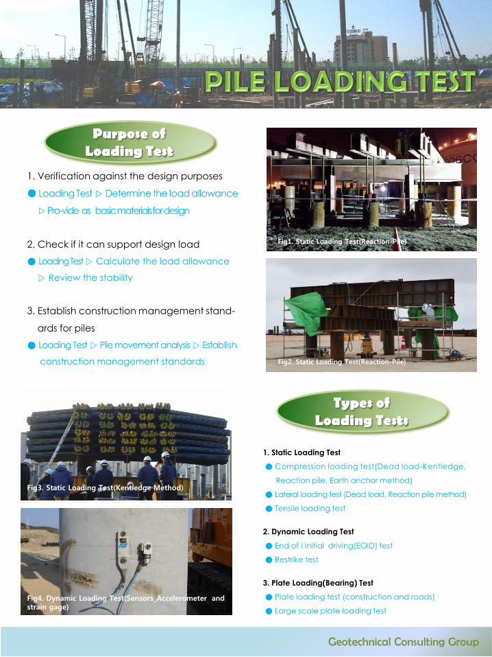
Purpose of Loading Test
1. Verification against the design purposes
● Loading Test ▷Determine the load allowance
▷Pro-vide as basic materials for design
2. Check if it can support design load
● Loading Test ▷ Calculate the load allowance
▷ Review the stability
3. Establish construction management stand-
ards for piles
● Loading Test ▷ Pile movement analysis ▷Establish
construction management standards
Types of Loading Tests
1. Static Loading Test
● Compression loading test(Dead load-Kentledge,
Reaction pile, Earth anchor method)
● Lateral loading test (Dead load, Reaction pile method)
● Tensile loading test
2. Dynamic Loading Test
● End of i Initial driving(EOID) test
● Restrike test
3. Plate Loading(Bearing) Test
● Plate loading test (construction and roads)
● Large scale plate loading test
Fig3. Static Loading Test(Kentledge Method)
Fig4. Dynamic Loading Test(Sensors_Accelerometer and strain gage)
Fig1. Static Loading Test(Reaction-Pile)
Geotechnical Consulting Group
Fig2. Static Loading Test(Reaction-Pile)
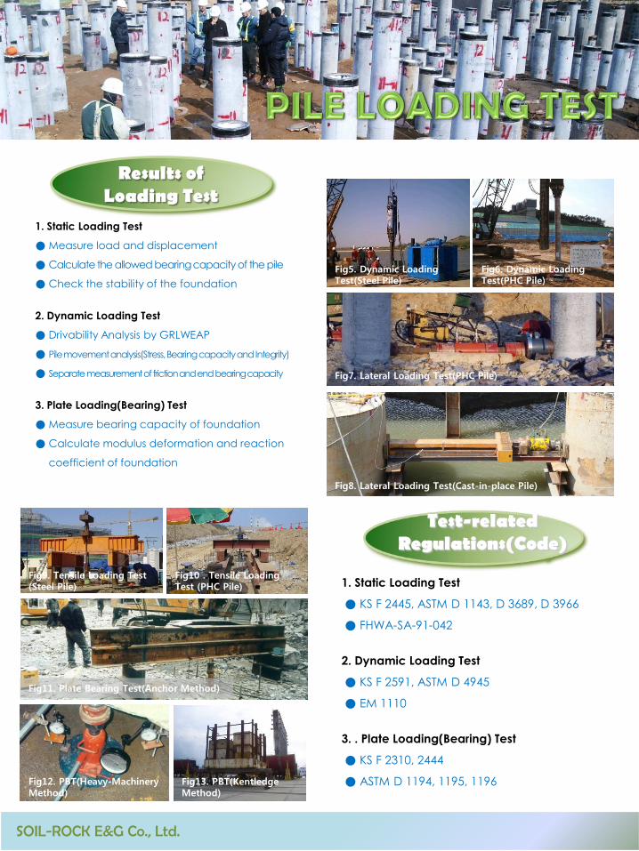
1. Static Loading Test
● Measure load and displacement
● Calculate the allowed bearing capacity of the pile
● Check the stability of the foundation
2. Dynamic Loading Test
● Drivability Analysis by GRLWEAP
● Pile movement analysis(Stress, Bearing capacity and Integrity)
● Separate measurement of friction and end bearing capacity
3. Plate Loading(Bearing) Test
● Measure bearing capacity of foundation
● Calculate modulus deformation and reaction
coefficient of foundation
Results of Loading Test
Test-related Regulations(Code)
1. Static Loading Test
● KS F 2445, ASTM D 1143, D 3689, D 3966
● FHWA-SA-91-042
2. Dynamic Loading Test
● KS F 2591, ASTM D 4945
● EM 1110
3. . Plate Loading(Bearing) Test
● KS F 2310, 2444
● ASTM D 1194, 1195, 1196
Fig5. Dynamic Loading Test(Steel Pile)
Fig6. Dynamic Loading Test(PHC Pile)
Fig7. Lateral Loading Test(PHC Pile)
Fig9. Tensile Loading Test (Steel Pile)
Fig11. Plate Bearing Test(Anchor Method)
Fig13. PBT(Kentledge Method)
Fig12. PBT(Heavy-Machinery Method)
Fig10 . Tensile Loading Test (PHC Pile)
SOIL-ROCK E&G Co., Ltd.
Fig8. Lateral Loading Test(Cast-in-place Pile)

■ Test using end bearing capacity of the pile
and mutual reaction force of circumference
friction by installing bi-directional jacks at the
end of cast-in-place piles
Principle of Bi-directional Load Test
Advantages and Disadvantages
1. Advantages
● Cost-efficient and safe when test load is big
● Can measure the friction and end bearing capacity at the same time
● Reduce work space and high efficiency
● Limited ton specific piles and low applicability
● Equilibrium between friction and end bearing capacity
and Jack can be wasted
2. Disadvantages
Test Result(Measurement Items)
● Measure load, upward, downward and pile top displacement
● Equivalent load-settlement curve drawing
● Calculate allowable bearing capacity and evaluate basic stability
Geotechnical Consulting Group

1. Test Hole Method ; CSL(Cross-hole Sonic Logging)
2. Sonic Echo Method ; PIT(Pile Integrity Test)
Integrity TestMethods
TEST14-1L=4.00 metersSpacing=1.320 mGain=9922009-09-04 14:31
0.5
11.5
22.5
33.5
4
Depth
(m
ete
rs)
0 2000 4000 6000
Wavespeed (m/sec)
lowhigh
Energy (log)
TEST14-1L=4.00 metersSpacing=1.320 mGain=992 (x16)2009-09-04 14:31
3.94
0.5
11.5
22.5
33.5
4
Depth
(m
ete
rs)
.25 .3 .35 .4 .45 .5 .55 .6 .65 .7
Time (ms)
■ To check the integrity of cast-in-place piles.
In other words, to check the internal defects
such as material separation, pores and section
change
Purpose ofIntegrity Test
● Need to make a test hole before construction
● Numbers and paths of test holes
Test Hole Method(Cross-hole Sonic Logging)
Diameter of pile
(D ; m)
Number of test-
ingtubes(EA)
Number of t
esting pathsRemark
D ≤ 0.6 Over 2 1
0.6 〈 D ≤ 1.2 Over 3 3
1.2 〈 D ≤ 1.5 Over 4 6
1.5 〈 D ≤ 2.0 Over 5 10
2.0 〈 D ≤ 2.5 Over 7 21
● Can be tested 7 days after the concrete deposit
● Measure thearrival time and signal sizeby ultrasonicwave
● Related regulations ; ASTMD6760,pp6-27 Highway
Construction Specified Specifications(Korea)
-0.2
0
0.2
0.4
0.6
0 2 4 6 8 10
Time(ms)
Vel(cm
/sec)
Sonic Echo Method(PIT)
● No need of test holes(sonic echo method)
● Issue stress wave after attaching an accelerome-
ter on the top of the pile
● Measure the particle velocity of the top of the
pile against micro time
● Check impedance (EA/C) of the pile
● Related regulations(Code) ; ASTM D 5882
Fig1. Test Hole Method(CSL)
Fig2. Sonic Echo Method(PIT)
SOIL-ROCK E&G Co., Ltd.
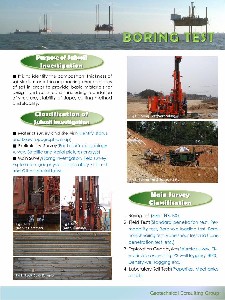
■ It is to identify the composition, thickness of
soil stratum and the engineering characteristics
of soil in order to provide basic materials for
design and construction including foundation
of structure, stability of slope, cutting method
and stability.
Purpose of SubsoilInvestigation
■ Material survey and site visit(Identify status
and Draw topographic map)
■ Preliminary Survey(Earth surface geology
survey, Satellite and Aerial pictures analysis)
■ Main Survey(Boring investigation, Field survey,
Exploration geophysics, Laboratory soil test
and Other special tests)
Classification of Subsoil Investigation
1. Boring Test(Size ; NX, BX)
2. Field Tests(Standard penetration test, Per-
meability test, Borehole loading test, Bore-
hole shearing test, Vane shear test and Cone
penetration test etc.)
3. Exploration Geophysics(Seismic survey, El-
ectrical prospecting, PS well logging, BIPS,
Density well logging etc.)
4. Laboratory Soil Tests(Properties, Mechanics
of soil)
Main Survey Classification
Fig3. SPT (Donut Hammer)
Fig4. SPT(Auto Hammer)
Fig5. Rock Core Sample
Fig1. Boring Test(Verticality)
Fig2. Boring Test( horizontality )
Geotechnical Consulting Group
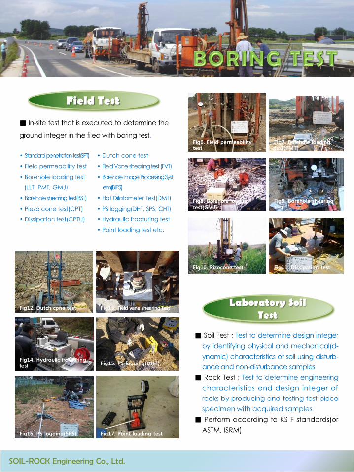
■ In-site test that is executed to determine the
ground integer in the filed with boring test.
Field Test
• Standardpenetrationtest(SPT)
• Field permeability test
• Borehole loading test
(LLT, PMT, GMJ)
• Boreholeshearingtest(BST)
• Piezo cone test(CPT)
• Dissipation test(CPTU)
• Dutch cone test
• FieldVane shearingtest (FVT)
• BoreholeImageProcessingSyst
em(BIPS)
• Flat Dilatometer Test(DMT)
• PS logging(DHT, SPS, CHT)
• Hydraulic fracturing test
• Point loading test etc.
■ Soil Test ; Test to determine design integer
by identifying physical and mechanical(d-
ynamic) characteristics of soil using disturb-
ance and non-disturbance samples
■ Rock Test ; Test to determine engineering
characteristics and design integer of
rocks by producing and testing test piece
specimen with acquired samples
■ Perform according to KS F standards(or
ASTM, ISRM)
Laboratory Soil Test
Fig6. Field permeability test
Fig7. Bolehole loading test(PMT)
Fig8. Bolehole loading test(GMJ)
Fig9. Borehole shearing test
Fig10. Pizocone test Fig11. Dissipation test
Fig12. Dutch cone test Fig13. Field vane shearing test
Fig14. Hydraulic fracturing test
Fig15. PS logging(DHT)
Fig16. PS logging(SPS) Fig17. Point loading test
SOIL-ROCK Engineering Co., Ltd.

■ To discover and remove the things that
were assumed in the plan among ground
conditions and design.
1) Monitor to discover the signs of urgent hazards
2) Monitor to get information related to safety
during the construction
3) Monitor to improve construction method
4) Monitor to prepare for lawsuits
5) Monitor to verify theories
6) Monitor for underpinning
Purpose of Monitori-ngAdministration
-2% -2%
범 례
내공변위측정
지중변위측정
천단침하측정
숏크리트 응력측정
록볼트축력측정 (3M,4M)
-2%0.000
-2%
L OF TUNNELC
3M(4M)0.000
-2%
-2%
-2%
-2%
1.000
1.000
2.000 2.000
CL OF TUNNEL
■ Temporary structure Monitoring- Underground clinometer, Water levelmeter, Strain
gauge, Load cell, Tiltmeter, Surface settlement gauge
etc.
Performance Monit-oringAdministration
■ Soft Ground Monitoring- Underground clinometer, Water levelmeter , Piezo-
meter, Surface settlement plate, Multi-point extens-
ometer etc.
■ Tunnel Monitoring- Tape extensometer, Crown extensometer, Rod ex-
tensometer, Shotcrete stress cell, Rock bolt stressme-
ter etc.
■ Bridge Monitoring- Thermometer, Hygrometer, Weather vane_Anem-
ometer, Vibrometer, Strain gauge, Clinometer, Slag
meter, Extensometer, Expansion joint gauge etc.
장력계(시공중 이동식)
처짐계
장력계
A1A2
(시공중 이동식)
Fig1. Bridge monitoring(1) Fig2. Bridge monitoring(2)
Fig3. Automation monitoring
Fig4. Temporary structure monitoring(1)
Fig5. Temporary structure monitoring(2) Fig6. Tunnel monitoring
Geotechnical Consulting Group
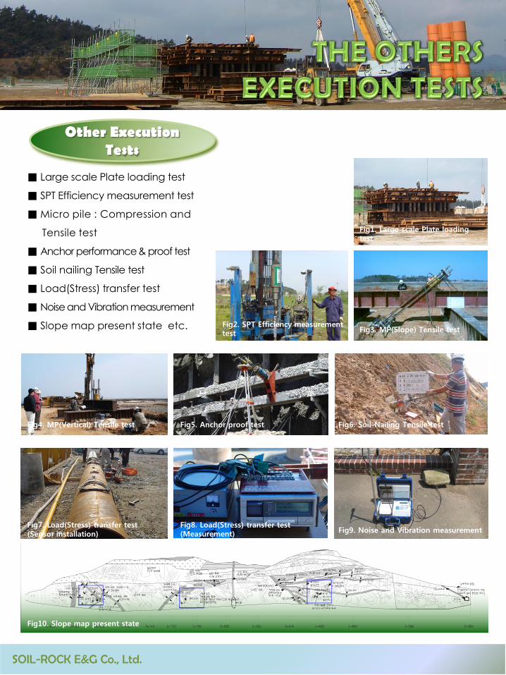
■ Large scale Plate loading test
■ SPT Efficiency measurement test
■ Micro pile : Compression and
Tensile test
■ Anchor performance& proof test
■ Soil nailing Tensile test
■ Load(Stress) transfer test
■ Noise and Vibration measurement
■ Slope map present state etc.
Other Execution Tests
Fig1. Large scale Plate loading test
Fig2. SPT Efficiency measurement test Fig3. MP(Slope) Tensile test
Fig5. Anchor proof test Fig6. Soil-Nailing Tensile test
Fig7. Load(Stress) transfer test (Sensor installation)
Fig8. Load(Stress) transfer test (Measurement) Fig9. Noise and Vibration measurement
Fig10. Slope map present state
Fig4. MP(Vertical) Tensile test
SOIL-ROCK E&G Co., Ltd.
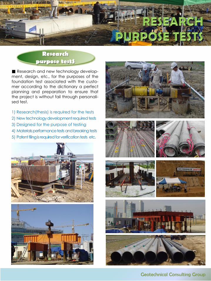
■ Research and new technology develop-
ment, design, etc., for the purposes of the
foundation test associated with the custo-
mer according to the dictionary a perfect
planning and preparation to ensure that
the project is without fail through personali-
sed test.
1) Research(thesis) is required for the tests
2) New technologydevelopmentrequired tests
3) Designed for the purpose of testing
4) Materialsperformancetests andbreakingtests
5) Patent filingis required forverificationtests etc.
Researchpurpose testS
Geotechnical Consulting Group

SOIL-ROCK E&G : Quality Inspection Agency Registration, Filed Engineering Activities Subject Registration
Jeonju Office ; 39-5, Utsamnye-gil, Wanju-gun, Jeonbuk, Korea Tel ; +82-63-255-3942, Fax ; +82-63-255-3943
Seoul Office ; 70, Cheonhoyet-gil, Gangdong-gu, Seoul, Korea Tel ; +82-2-529-3307~8, Fax ; +82-2-573-1371
Mokpo Office ; 42-43, Jijeok-ro, Mokpo-si, Jeonnam, Korea Tel ; +82-61-284-0116, Fax ; +82-61-282-2844
Busan Office ; 11, Jungang-daero 941beon-gil, Busanjin-gu, Busan, Korea Tel ; +82-51-861-6017, Fax ; +82-63-255-3943
Yangon Office ; No.78, 2nd Floor, Room 2.D, Kyaik Kasan Road, Tamwe Township, Yangon, Myanmar Tel ; +95-1-293365
• PILE LOADING TEST
• PILE INTEGRITY TEST
• Bi-DIRECTIONAL LOAD TEST
• PLATE BEARING TEST
• BORING TEST
• CONSTRUCTION MONITORING ADMINISTRATION
• GEOTECHNICAL CONSULTING
Always the right way can lead to a milestone_________