totalflow ngc8206 - abb
TRANSCRIPT

2101510-002 (AC)
TOTALFLOW®
NGC8206 User’s Manual

Intellectual Property & Copyright Notice ©2006, 2007 by ABB Inc., Totalflow (“Owner”), Bartlesville, Oklahoma 74006, U.S.A. All rights reserved. Any and all derivatives of, including translations thereof, shall remain the sole property of the Owner, regardless of any circumstances. The original US English version of this manual shall be deemed the only valid version. Translated versions, in any other language, shall be maintained as accurately as possible. Should any discrepancies exist, the US English version will be considered final. Notice: This publication is for information only. The contents are subject to change without notice and should not be construed as a commitment, representation, warranty, or guarantee of any method, product, or device by Owner. Inquiries regarding this manual should be addressed to ABB Inc., Totalflow Products, Technical Communications, 7051 Industrial Blvd., Bartlesville, Oklahoma 74006, U.S.A.
i
Table of Contents Introduction.............................................................................................................xi
About the Manual .........................................................................................................xi Getting Help................................................................................................................. xii Key Symbols................................................................................................................ xii Safety Practices and Precautions............................................................................... xiii
Chapter 1 System Description.............................................................................1-1 Overview.................................................................................................................... 1-1 Processing a Sample................................................................................................. 1-4
NGC8200 Hardware ...................................................................................................... 1-5 System Specifications................................................................................................ 1-5 NGC8200 Standard Hardware Features ................................................................... 1-6 Cast Aluminum Enclosure ......................................................................................... 1-7 Feed-Through Assembly (2102026-xxx) ................................................................... 1-9 Analytical Module..................................................................................................... 1-11 Digital Controller Assembly...................................................................................... 1-14 Termination Panel.................................................................................................... 1-16 Grounding the NGC................................................................................................. 1-17 Calibration/Validation Stream .................................................................................. 1-19 Operating Voltages and Cable Lengths................................................................... 1-19 Sample Transport Tubing Design............................................................................ 1-21 Calculating Lag Time............................................................................................... 1-23
Functionality of the NGC8200 ................................................................................... 1-25 NGC Standard Software Features........................................................................... 1-25 PCCU Local Communication Options...................................................................... 1-27 NGC Start-up Diagnostics ....................................................................................... 1-27 Start-up Wizard........................................................................................................ 1-28 Historical Data ......................................................................................................... 1-28
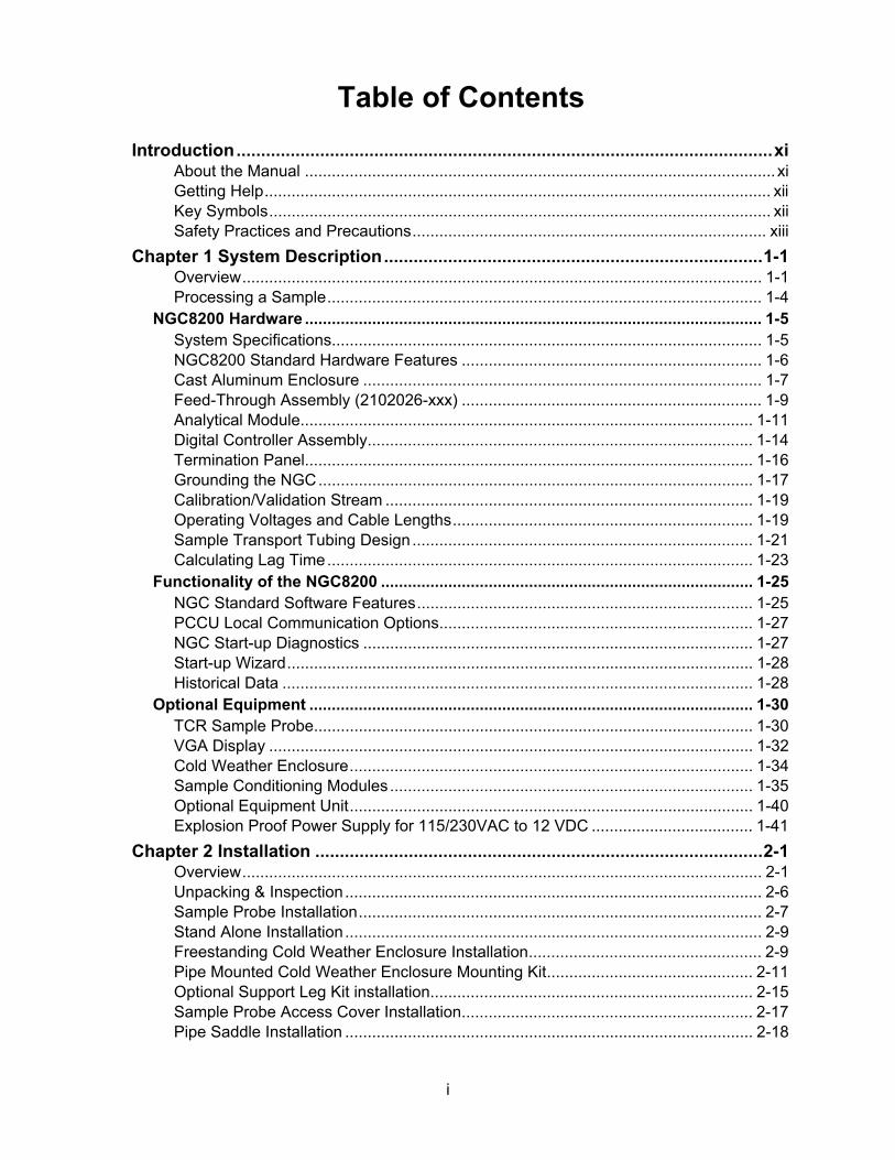
Optional Equipment ................................................................................................... 1-30 TCR Sample Probe.................................................................................................. 1-30 VGA Display ............................................................................................................ 1-32 Cold Weather Enclosure.......................................................................................... 1-34 Sample Conditioning Modules................................................................................. 1-35 Optional Equipment Unit.......................................................................................... 1-40 Explosion Proof Power Supply for 115/230VAC to 12 VDC .................................... 1-41
Chapter 2 Installation ...........................................................................................2-1 Overview.................................................................................................................... 2-1 Unpacking & Inspection............................................................................................. 2-6 Sample Probe Installation.......................................................................................... 2-7 Stand Alone Installation............................................................................................. 2-9 Freestanding Cold Weather Enclosure Installation.................................................... 2-9 Pipe Mounted Cold Weather Enclosure Mounting Kit.............................................. 2-11 Optional Support Leg Kit installation........................................................................ 2-15 Sample Probe Access Cover Installation................................................................. 2-17 Pipe Saddle Installation ........................................................................................... 2-18

ii
Shelf Installation ...................................................................................................... 2-19 Cold Weather Enclosure (CWE) Mounting Plate..................................................... 2-20 NGC Installation ...................................................................................................... 2-22 Sample Conditioning Module Installation ................................................................ 2-23 Sample Line Connections........................................................................................ 2-25 Sample Line(s) to NGC inside of Cold Weather Enclosure ..................................... 2-27 CWE Optional Pwr/Comm Outlet Box Assembly..................................................... 2-29 Carrier/Calibration Bottle Rack Installation on Meter Run ....................................... 2-36 CWE Carrier Gas Bottle Rack Installation ............................................................... 2-37 Carrier Gas Regulator with Low Pressure Switch Installation ................................. 2-39 CWE Calibration Gas Bottle Installation .................................................................. 2-40 Calibration Gas Regulator - Low Pressure Switch Installation ................................ 2-41 Carrier Gas and Calibration Gas Connections ........................................................ 2-43 Vent Line Connections ............................................................................................ 2-45 CWE Optional Catalytic Heater Installation ............................................................. 2-47 CWE Optional Electric Heater Installation ............................................................... 2-51 Optional Equipment Unit Installation ....................................................................... 2-53 Optional AC/DC Explosion Proof Power Supply Installation ................................... 2-57 Optional AC/12VDC Power Supply Installation ....................................................... 2-60 Optional 24 VDC/12 VDC Power Converter ............................................................ 2-63 Optional OEU Battery Pack Installation................................................................... 2-64 Optional 12V Solar Power Supply ........................................................................... 2-67 DC Power Installation .............................................................................................. 2-69 Remote Communication Installation........................................................................ 2-70
Chapter 3 NGC Start-up ....................................................................................... 3-1 Overview.................................................................................................................... 3-1 PCCU32 Installation and Setup................................................................................. 3-1 Ethernet Installation and Setup ................................................................................. 3-3 Connecting to the NGC’s Local Port.......................................................................... 3-7 NGC Diagnostics ....................................................................................................... 3-9 NGC Start-up Wizard................................................................................................. 3-9 Calibrating the NGC ................................................................................................ 3-14 Security System....................................................................................................... 3-16 Alarm Definitions ..................................................................................................... 3-17
Chapter 4 Maintenance ........................................................................................ 4-1 Overview.................................................................................................................... 4-1 Field Tool Kit.............................................................................................................. 4-3 Spare Part Components ............................................................................................ 4-3 Visual Inspection ....................................................................................................... 4-4 Backing up Configuration Files (Save & Restore) ..................................................... 4-4 Restore Configuration Files ....................................................................................... 4-5 Reset Procedures...................................................................................................... 4-6 Restore Factory Defaults........................................................................................... 4-8 Lithium Battery Status ............................................................................................... 4-9 Changing NGC Clock .............................................................................................. 4-10 Replacing Calibration or Carrier Gas Bottle(s) ........................................................ 4-11 Replacing Digital Controller Complete Assembly .................................................... 4-12 Digital Controller Assembly Mounting Bracket ........................................................ 4-14

iii
Replacing Display Board ......................................................................................... 4-15 Replacing Digital Controller Board........................................................................... 4-17 Replacing Analytical Module.................................................................................... 4-19 Replacing GC Module.............................................................................................. 4-22 Replacing Manifold Assembly.................................................................................. 4-25 Replacing Analytical Processor Assembly............................................................... 4-28 Replacing Termination Panel................................................................................... 4-32 Replacing Feed-Through Assembly ........................................................................ 4-34 Replacing Lithium Battery........................................................................................ 4-37 Replacing Frit Filters................................................................................................ 4-38 Replacing Feed-Through Interface Gasket.............................................................. 4-40 Replacing Feed-Through Manifold Gasket .............................................................. 4-42 Replacing Termination Panel to Digital Controller Cable......................................... 4-44 Replacing Analytical Processor to GC Module Cable.............................................. 4-46 Replacing Analytical Processor to Termination Panel Cable................................... 4-49 Replacing Temperature Sensor to GC Module Cable ............................................. 4-51
Chapter 5 Troubleshooting ..................................................................................5-1 Overview.................................................................................................................... 5-1
Start-up Diagnostic Troubleshooting......................................................................... 5-4 Overview.................................................................................................................... 5-4 Carrier Pressure Regulator Test................................................................................ 5-5 Oven Temperature Test............................................................................................. 5-6 Processor Control Test .............................................................................................. 5-7 Stream Test ............................................................................................................... 5-8
Troubleshooting Alarms............................................................................................ 5-10 Overview.................................................................................................................. 5-10 Pressure Regulator 1 or 2 Alarm ............................................................................. 5-12 Sample Pressure Alarm........................................................................................... 5-13 Oven Temperature Error Alarm ............................................................................... 5-15 No Stream Valve Selected Alarm ............................................................................ 5-15 Digital-Analog Board Communication Error Alarm .................................................. 5-16 Calculation Error Alarm............................................................................................ 5-17 Calibration Un-Normalized Error Alarm ................................................................... 5-18 Stream Sequence Error Alarm................................................................................. 5-19 Calibration CV Percent Error Alarm......................................................................... 5-19 Calibration RF Percent Error Alarm......................................................................... 5-20 Enclosure Temperature Alarm................................................................................. 5-21 Power Supply Alarm ................................................................................................ 5-22 Low Carrier Gas Bottle (DI1) Alarm......................................................................... 5-22 Low Cal Gas Bottle (DI2) Alarm............................................................................... 5-23 GCM Processing Error Alarm .................................................................................. 5-23 Bad Bead Alarm....................................................................................................... 5-24 No Pilot Valve Change Detected Alarm................................................................... 5-24 Sample Flow Detection Alarm ................................................................................. 5-24 CPU Loading Alarm................................................................................................. 5-25 System Memory Available Alarm............................................................................. 5-25 RAM File Available Alarm........................................................................................ 5-26 FLASH File Available Alarm .................................................................................... 5-27

iv
Missing Peak-Calibration Not Used......................................................................... 5-27 Stream Un-Normalized Total ................................................................................... 5-28
Alarm Troubleshooting Tests ................................................................................... 5-29 Sample Vent Pressure Test..................................................................................... 5-29 Column Vent Pressure Test .................................................................................... 5-29 Sample Pressure Test ............................................................................................. 5-30 Feed-Through Assembly Blockage Test ................................................................. 5-30 Temperature Sensor Test........................................................................................ 5-31 Abnormal Calibration Gas Depletion ....................................................................... 5-31
Power Troubleshooting ............................................................................................. 5-32 Overview.................................................................................................................. 5-32 Power Supply Voltage Test ..................................................................................... 5-33 Equipment Isolation Test ......................................................................................... 5-34 NGC Module Isolation Test ..................................................................................... 5-35 Charger Circuit Test ................................................................................................ 5-36 Solar Panel Troubleshooting Test ........................................................................... 5-37 AC Charger/Power Supply Troubleshooting Test.................................................... 5-39
Troubleshooting Communications........................................................................... 5-41 Overview.................................................................................................................. 5-41 Transceiver Supply Voltage Test............................................................................. 5-43 12V Communication Supply Voltage Test ............................................................... 5-43 Transceiver Check................................................................................................... 5-44 RS-232 Communication Test .................................................................................. 5-45 RS-485 Communications......................................................................................... 5-46 RS-485 Communication Test .................................................................................. 5-47
Appendix A Modbus Registers ...........................................................................A-1 Appendix B Totalflow® Definitions and Acronyms ...........................................B-1 Appendix C Drawings ..........................................................................................C-1

v
Table of Figures Figure 1—1 Typical Single Stream Installation ................................................................. 1-2 Figure 1—2 Typical Multi-stream Installation .................................................................... 1-3 Figure 1—3 Modular Design NGC8200 ............................................................................ 1-6 Figure 1—4 NGC8200 Enclosure ..................................................................................... 1-7 Figure 1—5 NGC8200 Enclosure Left Side ...................................................................... 1-8 Figure 1—6 NGC8200 Enclosure Right Side.................................................................... 1-8 Figure 1—7 NGC8200 Enclosure Underside .................................................................... 1-9 Figure 1—8 NGC Feed-Through Assembly (2102026-xxx) ............................................ 1-10 Figure 1—9 Analytical Module ........................................................................................ 1-11 Figure 1—10 GC Module Assembly................................................................................ 1-12 Figure 1—11 Manifold Assembly .................................................................................... 1-13 Figure 1—12 Analytical Processor Assembly ................................................................. 1-14 Figure 1—13 Digital Controller Assembly with Optional Display..................................... 1-15 Figure 1—14 Digital Controller Board ............................................................................. 1-15 Figure 1—15 Termination Panel ..................................................................................... 1-16 Figure 1—16 NGC Grounding Considerations................................................................ 1-18 Figure 1—17 Heat Tracing Sample Line......................................................................... 1-23 Figure 1—18 Typical Sample Installation Diagram......................................................... 1-24 Figure 1—19 Temperature Compensated Regulator With Sample Probe...................... 1-31 Figure 1—20 Optional NGC VGA Display Screens ........................................................ 1-33 Figure 1—21 NGC8200 Cold Weather Enclosure Installation w/ Catalytic Heater ......... 1-34 Figure 1—22 Available Sample Conditioning Modules ................................................... 1-35 Figure 1—23 Single Stream Sample Conditioning Assembly ......................................... 1-37 Figure 1—24 Multiple Stream Sample Conditioning Assembly....................................... 1-37 Figure 1—25 Single Stream Conditioning Module Dimensions ...................................... 1-38 Figure 1—26 Multiple Stream Conditioning Module Dimensions.................................... 1-38 Figure 1—27 NGC End Cap Tabs for Security Seal ....................................................... 1-39 Figure 1—28 Security Wire with Seal ............................................................................. 1-39 Figure 1—29 Explosion Proof AC Power Supply ............................................................ 1-41 Figure 2—1 Basic Meter Run Installation.......................................................................... 2-2 Figure 2—2 Typical Wall Shelf Mount Installation............................................................. 2-3 Figure 2—3 Typical Cold Weather Enclosure with Electric Heater ................................... 2-3 Figure 2—4 Sample Probe................................................................................................ 2-8 Figure 2—5 Sample Probe Insertion................................................................................. 2-8 Figure 2—6 Typical CWE Stand Mount Installation ........................................................ 2-10 Figure 2—7 CWE Mounting Hardware............................................................................ 2-11 Figure 2—8 Mounting Brackets....................................................................................... 2-12 Figure 2—9 Mounting Hardware Installation................................................................... 2-12 Figure 2—10 Adjustment Assembly................................................................................ 2-13 Figure 2—11 Sample Probe Access Plates .................................................................... 2-14 Figure 2—12 Pipe Mount installation .............................................................................. 2-14 Figure 2—13 Chain Retainer Lock.................................................................................. 2-15

vi
Figure 2—14 Optional Support Leg Overview .................................................................2-16 Figure 2—15 Installed Sample Probe and Access Plate Insulation.................................2-17 Figure 2—16 Typical Pipe Saddle Installation .................................................................2-19 Figure 2—17 Shelf Installation.........................................................................................2-20 Figure 2—18 NGC Mounting Plate ..................................................................................2-21 Figure 2—19 Cold Weather Enclosure Interior ................................................................2-21 Figure 2—20 NGC Mounting ...........................................................................................2-22 Figure 2—21 NGC Optional Mounting Flange Pipe.........................................................2-23 Figure 2—22 Sample Conditioning Module Bracket ........................................................2-24 Figure 2—23 Sample System Mounting Kits ...................................................................2-25 Figure 2—24 Sample Conditioning Module Installation ...................................................2-26 Figure 2—25 Sample Boot...............................................................................................2-28 Figure 2—26 CWE Access Panel Removed....................................................................2-30 Figure 2—27 Power Communication Outlet Box Assembly.............................................2-30 Figure 2—28 Assembled Power/Communication Assembly............................................2-32 Figure 2—29 Power Wiring Diagram ...............................................................................2-32 Figure 2—30 Suggested RS-232 Wiring Instructions ......................................................2-35 Figure 2—31 Suggested RS-485 Wiring Instructions ......................................................2-35 Figure 2—32 Suggested RS-422 Wiring Instructions ......................................................2-36 Figure 2—33 Carrier/Calibration Gas Bottle Rack Installation.........................................2-37 Figure 2—34 Dual Bottle Rack Assembly........................................................................2-38 Figure 2—35 Dual Bottle Rack Installation ......................................................................2-38 Figure 2—36 Carrier Gas Pressure Regulator with Relief Valve .....................................2-39 Figure 2—37 Carrier Gas Low Pressure Switch Wiring Instructions ...............................2-40 Figure 2—38 Calibration Bottle Location .........................................................................2-41 Figure 2—39 Calibration Gas Pressure Regulator with Relief Valve...............................2-42 Figure 2—40 Calibration Blend Low Pressure Switch Wiring Instruction ........................2-42 Figure 2—41 Carrier and Calibration Gas Connections ..................................................2-44 Figure 2—42 Vent Line Connections on Feed-Through Assembly..................................2-46 Figure 2—43 Catalytic Heater Option in Cold Weather Enclosure ..................................2-48 Figure 2—44 Catalytic Heater Assembly .........................................................................2-48 Figure 2—45 Thermostat Assembly Installed ..................................................................2-48 Figure 2—46 Regulator Assembly Installed.....................................................................2-50 Figure 2—47 Temperature Probe Installation..................................................................2-50 Figure 2—48 Electrical Pre-heater Wiring Instructions ....................................................2-51 Figure 2—49 Electric Heater Installed in CWE ................................................................2-52 Figure 2—50 Electric Heater Option Wiring Instructions .................................................2-52 Figure 2—51 6470 OEU Pipe Mounting Installation ........................................................2-54 Figure 2—52 6770 OEU Pipe Mounting Installation ........................................................2-55 Figure 2—53 6470 OEU Wall Mounted Installation .........................................................2-55 Figure 2—54 6770 OEU Wall Mounted Installation .........................................................2-56 Figure 2—55 Explosion Proof AC Power Supply Top/Front Dimensions ........................2-57 Figure 2—56 Explosion Proof AC Power Supply Side Dimensions.................................2-58 Figure 2—57 Explosion Proof AC Power Supply Wiring Instructions ..............................2-59 Figure 2—58 6470 OEU Unit with Power Supply ............................................................2-60

vii
Figure 2—59 6770 OEU Unit with Power Supply............................................................ 2-61 Figure 2—60 AC/DC Converter Wiring Instructions........................................................ 2-62 Figure 2—61 24VDC/12VDC Power Supply Converter .................................................. 2-64 Figure 2—62 Optional 6770 OEU Enclosure .................................................................. 2-65 Figure 2—63 Battery Pack With Solar Panel Wiring Instructions.................................... 2-66 Figure 2—64 Battery Pack With AC Power Supply Wiring Instructions .......................... 2-66 Figure 2—65 Solar Power Supply Wiring Instructions .................................................... 2-68 Figure 3—1 Ethernet Connections.................................................................................... 3-3 Figure 3—2 Ethernet Cable-Typical.................................................................................. 3-4 Figure 3—3 Ethernet Cable-Cross-Over........................................................................... 3-5 Figure 3—4 MMI Communication Cables ......................................................................... 3-7 Figure 3—5 Typical Chromatograph for Chrom-1 (Heavies) .......................................... 3-15 Figure 3—6 Typical Chromatograph for Chrom-2 (Lights).............................................. 3-16 Figure 4—1 Digital Controller Complete Assembly........................................................... 4-7 Figure 4—2 VGA Display Board ..................................................................................... 4-13 Figure 4—3 Digital Controller Board ............................................................................... 4-18 Figure 4—4 Analytical Module ........................................................................................ 4-20 Figure 4—5 Analytical Processor Board ......................................................................... 4-21 Figure 4—6 GC Module, Exploded View ........................................................................ 4-24 Figure 4—7 Manifold Assembly ...................................................................................... 4-27 Figure 4—8 Analytical Processor Assembly, Exploded from Manifold ........................... 4-30 Figure 4—9 Termination Panel ....................................................................................... 4-33 Figure 4—10 Feed-Through Assembly ........................................................................... 4-35 Figure 4—11 Primary Component Side Digital Controller Board .................................... 4-38 Figure 4—12 Feed-Through Assembly, Exploded View ................................................. 4-39 Figure 4—13 GC Module Electronic Board..................................................................... 4-52 Figure 4—14 Manifold Cable Keeper.............................................................................. 4-53 Figure 5—1 Troubleshooting Flowchart ............................................................................ 5-3 Figure 5—2 Power Troubleshooting Flowchart............................................................... 5-32 Figure 5—3 Solar Panel Wiring Instructions ................................................................... 5-38 Figure 5—4 AC Charger/Power Supply Wiring ............................................................... 5-40 Figure 5—5 Communication Troubleshooting Flowchart ................................................ 5-42

viii
BBBlllaaannnkkk PPPaaagggeee

ix
List of Tables Table 1-1 Hydrocarbons.................................................................................................... 1-4 Table 1-2 Calibration Gas Blend Recommended Components ...................................... 1-19 Table 1-3 12V Battery Power Supply System Maximum Cable Lengths ........................ 1-20 Table 1-4 AC Power Supply System Maximum Cable Lengths ...................................... 1-20 Table 1-5 Internal Volume of Commonly Used Sample Transport Tubing...................... 1-21 Table 1-6 Calculation File Settings ................................................................................. 1-26 Table 1-7 Communication Option Comparison ............................................................... 1-27 Table 1-8 Optional Temperature Compensated Regulator (TCR) .................................. 1-30 Table 2-1 Port 1 and Port 2 Pin-Outs/Terminations ........................................................ 2-70 Table 3-1 Station Setup Screen Information ................................................................... 3-10 Table 3-2 Stream Setup Screens.................................................................................... 3-11 Table 3-3 Defaulted Alarm Definitions ............................................................................ 3-18 Table 4-1 Tool Requirements............................................................................................ 4-3 Table 5-1 NGC8200 Alarms............................................................................................ 5-10 Table 5-2 Specifications for Solar panels........................................................................ 5-37 Table 5-3 RS-232 Field Wiring on NGC Termination Panel............................................ 5-45 Table 5-4 RS-485 Terminations ...................................................................................... 5-46 Table 5-5 RS-485 Field Wiring on NGC Termination Panel............................................ 5-47

x
BBBlllaaannnkkk PPPaaagggeee

xi
Introduction
About the Manual
This manual is written to provide an experienced chromatography technician with the requirements necessary to install, setup and operate the Totalflow® Model NGC8200 Natural Gas Chromatograph.
Organization & Style
Each of the chapters in this manual presents information in an organized and concise manner. Readers are able to look at the headings and get a broad picture of the content without reading every word. Also, there are overviews at the beginning of each chapter that provides you with an idea of what is in the chapter, and how it fits into the overall manual.
Highlights This manual provides the following information:
Chapter Description
1) System Description Provides a description of the Totalflow NGC system components and specifications.
2) Installation Includes unpacking and detailed procedures for setup and installation.
3) Start-up Provides you with a tutorial on how to get a newly installed NGC system up and running.
4) Maintenance Provides Procedures on how to remove and replace major modules,
5) Troubleshooting Provides a troubleshooting chart and procedures on how to correct most problems.
Appendix A Modbus Registers
Modbus Register List
Appendix B Definitions & Acronyms
Provides quick access to the majority of terms and acronyms, as well as their definitions.
Appendix C Drawings Provides a place to store the drawings that were provided with the equipment.

xii
Getting Help
At Totalflow, we take pride in the on going support we provide our customers. When you purchase a product, you receive documentation which should answer your questions; however, Totalflow Technical Support provides you an 800 number as an added source of information. If you require assistance, call:
USA: (800) 442-3097 or International: 001-918-338-4888
Before You Call
• Know your Totalflow’s model and serial number. Serial numbers can be found on a plate located on each unit.
• Be prepared to give the customer service representative a detailed description of the problem.
• Note any alarms or messages as they appear. • Prepare a written description of problem. • Know your software version, board and optional part numbers.
Key Symbols
The following symbols are used frequently in the manual. These are intended to catch your eye and draw your attention to important information.
Intended to draw your attention to useful information or to clarify a statement made earlier.
Intended to draw your attention to a fact that may be useful or helpful in understanding a concept.
Intended to draw your attention to information regarding security access to equipment and Software Security features.
Intended to draw your attention to a statement regarding the likelihood of personal injury or fatality that could result from improper access or techniques used while working in hazardous locations. Please refer to the “Safety Practices and Precaution” section for additional information.
Intended to draw your attention to a statement that might keep you from making a mistake, keep you from destroying equipment or parts, or keep you from creating a situation that could cause personal injury if caution is not used. Please refer to the “Safety Practices and Precaution” section for additional information.

xiii
Safety Practices and Precautions
This manual contains information and warnings which have to be followed by the user to ensure safe operation and to retain the product in a safe condition. Installation, maintenance and repairs should only be performed by a trained and qualified technician. Please refer to Certification Drawings shipped with this unit for specific guidelines. Extra copies of the certification drawings, referenced on the unit Name Tag, can be obtained, free of charge, by contracting Totalflow Technical Support at the number listed in the “Getting Help” section.
Safety Guidelines
DO NOT open or remove covers, including the PCCU Local Communications cover, unless the area is known to be Non-hazardous, including the internal volume of the enclosure. DO NOT open the equipment to perform any adjustments, measurements, maintenance, parts replacement or repairs until all external power supplies have been disconnected. Installation and maintenance must be performed by person(s) qualified for the type and area of installation according to National and Local codes. When opening covers or removing parts, exercise extreme care “live parts or connections can be exposed”. Capacitors in the equipment can still be charged even after the unit has been disconnected from all power supplies.
Safety First Various statements in this manual identified as conditions or practices that could result in equipment damage, personal injury or loss of life will be highlighted using the following Icons.
Exercise caution while performing this task. Carelessness could result in damage to the equipment, other property and personal injury.
Stop. Do not proceed without first verifying that a hazardous condition does not exist. This task may not be undertaken until proper protection has been accomplished, or the hazardous condition has been removed. Personal injury or fatality could result. Examples of these warnings include: • Removal of enclosure cover(s) in a hazardous location
must follow guidelines stipulated in the Certification Drawings shipped with this unit.
• If unit is installed or to be installed in a hazardous location, technician must follow the guidelines stipulated in the Certification Drawings shipped with this unit.
• Access to unit via PCCU cable in a hazardous location must follow guidelines stipulated in the Certification Drawings shipped with this unit.
Continued on Next Page

xiv
Safety Practices and Precautions, Cont.
Safety First, Cont.
• Connecting or disconnecting equipment in a hazardous location for installation or maintenance of electric components must follow guidelines stipulated in the Certification Drawings shipped with this unit.
DANGER indicates a personal injury hazard immediately accessible as one reads the markings. CAUTION indicates a personal injury hazard not immediately accessible as one reads the markings, or a hazard to property, including the equipment itself.
Equipment Markings
Protective ground (earth) terminal
Grounding the Product
If a grounding conductor is required, it should be connected to the grounding terminal before any other connections are made.
Operating Voltage
Before switching on the power, check that the operating voltage listed on the equipment agrees with the power being connected to the equipment.
Danger From Loss of Ground
A grounding conductor may or may not be required depending on the hazardous classification. If required, any interruption of the grounding conductor inside or outside the equipment or loose connection of the grounding conductor can result in a dangerous unit. Intentional interruption of the grounding conductor is not permitted.
Safe Equipment
If it is determined that the equipment cannot be operated safety, it should be taken out of operation and secured against unintentional usage.

1-1
Chapter 1 System Description
Overview
This Chapter introduces you to the Totalflow® Model NGC8200 Series Natural Gas Chromatograph (NGC). The NGC is designed to continually analyze natural gas streams, on-site, determine composition, calorific value, and store the analysis information. It is designed for natural gas streams, 800 to 1500 Btu/scf (29.8 to 55.9 Megajoules/meter3) with less than 100 PPM H2S. The unit is a fully functional gas chromatograph for “Pipeline Quality” natural gas, designed to analyze natural gas streams, dry of both hydrocarbon liquids and water. The unit can collect and retain analysis information for one to four independent sample streams. Applicable installations include: Transmission, Distribution, Custody Transfer with Metrology quality results, Production, Gas Gathering and End User Gas Markets.
Highlights This Chapter covers the following topics:
Topic See Page Processing a Sample 1-4 NGC8200 Hardware 1-5 System Specifications 1-5 NGC8200 Standard Hardware Features 1-6 Cast Aluminum Enclosure 1-7 Feed-Through Assembly (2102026-xxx) 1-9 Analytical Module 1-11 Digital Controller Assembly 1-14 Termination Panel 1-16 Grounding the NGC 1-17 Calibration/Validation Stream 1-19 Operating Voltages and Cable Lengths 1-19 Sample Transport Tubing Design 1-21 Calculating Lag Time 1-23 Functionality of the NGC8200 1-25 NGC Standard Software Features 1-25 PCCU Local Communication Options 1-27 NGC Start-up Diagnostics 1-27 Start-up Wizard 1-28 Historical Data 1-28 Optional Equipment 1-30 TCR Sample Probe 1-30 VGA Display 1-32
Continued on Next Page

1-2
Overview, Cont.
Highlights, Cont.
Topic See Page Cold Weather Enclosure 1-34 Sample Conditioning Modules 1-35 Optional Equipment Unit 1-40 Explosion Proof Power Supply for 115/230VAC to 12 VDC 1-41
Framework Based on ABB Totalflow XSeries technology, the NGC features a common platform that combines the expandable framework of the XSeries equipment with the capabilities of a remote gas chromatograph. This expandability allows the NGC to run other applications such as AGA-3 and AGA-7 while simultaneously doing stream analysis. This new platform is designed for operation on Windows CE Real Time Operating System.
Calibration Once installed on the meter run, the unit can immediately calculate the calorific value of natural gas. You may use your own calibration blend to adjust the unit to your company’s standards or take advantage of some automatic operational features by using the recommended calibration gas.
Typical Installation
This compact unit will require minimal installation time and is fully configured and calibrated at the factory. A typical single stream pipeline installation would include a Sample Probe, optional Sample Conditioning Module, Carrier and Calibration Gas (see Figure 1—1). A multiple stream pipeline installation would include an installation where Sample Probes may be connected to the NGC (see Figure 1—2).
INCREASE
DECREASE
CALIBRATION GASCARRIER GAS
SAMPLE PROBE
NGC8200
SAMPLE CONDITIONINGMODULE
INCREASE
DECREASE
Figure 1—1 Typical Single Stream Installation
Continued on Next Page

1-3
Overview, Cont.
Figu
re 1
—2
Typi
cal M
ulti-
stre
am In
stal
latio
n
Not
e: F
or c
larit
y, u
nit i
s sh
own
mou
nted
on
outs
ide
met
er ru
n.
For s
ampl
e lin
e le
ngth
con
side
ratio
n, th
e un
it sh
ould
be
mou
nted
on
mid
dle
pipe
run.
STR
EA
M 2
SA
MPL
E PR
OBE
STR
EAM
1 S
AM
PLE
PRO
BE
NG
C82
00
SA
MP
LE C
ON
DIT
ION
ING
MO
DU
LES
STR
EAM
3 S
AM
PLE
PRO
BE
INC
REAS
E
DEC
REAS
E
CA
LIB
RA
TIO
N G
AS
CAR
RIE
R G
AS

1-4
Processing a Sample
A natural gas sample is extracted from the pipeline, processed for particulate removal and phase integrity by the Sample Conditioning System (optional as required), transported to the NGC, injected onto the chromatographic columns where component separation occurs. The NGC analyzes each sample utilizing established chromatographic techniques. The resulting information consists of mole percent values for each component. These values are used to perform energy calculations. Calculated values include: Gas Compressibility, Real Relative Density, Btu/CV Value, Liquid GPM, Wobbe Index, Methane Number and several other optional calculated values. Gas Compressibility selections include NX-19, AGA-8 Detail, Single Virial Summation Factor, ISO Summation Factor and None (a factor of one is used). The processed sample is then vented with the carrier gas and results are stored in memory and communicated to other devices as needed. All of these values as well as composition are available on various modbus communication protocols.
Hydrocarbons To further define the natural gas components, Table 1-1 gives additional details for each hydrocarbon. Among the more informative columns, key information includes the Boiling Point of the component. The Boiling Point of each component correlates to the order each component will exit the column.
Table 1-1 Hydrocarbons
Molecular Formula
Common Abbreviation
Component Boiling Point ( C)
C1H4 C1 Methane -161.6
C2H4 C2= Ethylene -103.75 C2H6 C2 Ethane -88.65 C3H6 C3= Propylene -47.65 C3H8 C3 Propane -42.05
C4H10 IC4 Isobutane -11.65 C4H8 C4= Butylene -6.95
C4H10 C4 Butane -.45 C5H12 NeoC5 Neopentane 9.85 C5H12 IC5 Isopentane 27.85 C5H12 C5 Pentane 34.85 C6H14 C6 Hexane 68.85 C7H16 C7 Heptane 97.85 C8H18 C8 Octane 125.55 C9H20 C9 Nonane 150.95
C10H22 C10 Decane 173.95

1-5
NGC8200 Hardware
System Specifications
12 VDC 24VDC
No Aux. Heater W/Aux. Heater No Aux. Heater W/Aux. Heater
Supply Voltage 10.5–16VDC 10.5–16VDC 21–28VDC 21–28VDC
Recommend AC Power Supply 14.5V 14.5V 25V 25V
Maximum Instantaneous Current1 4 Amp 8.2 Amp 2.2Amp 5.2Amp
Avg. Power Consumption After Startup2 Up to 7 Watts Up to 53 Watts Up to 7 Watts Up to 64 Watts
Storage -22°F to +140°F (-30° to 60°C)
Normal Operation 0°F to +131°F (-18°C to 55°C) Environmental Temperature
W/Cold Weather Enclosure -40°F to +131°F (-40° to 55°C)
Repeatability ± 0.125 Btu @ 1,000 Btu (±0.0125%) ambient; ±0.25 Btu @ 1,000 Btu (±0.025%) over temp. range of 0–131°F (-18° to 55°C)
Helium Carrier Consumption rate: 12 ml/minute typical to 20 ml/minute maximum.
Medium 800 to 1500 Btu per Standard Cubic Foot (29.8 to 44.6 megajoules/meter3) with less than 100 PPM H2S
Analysis Time Approx. 5 minutes; interval between cycles is adjustable.
Calibration/Validation Streams
Up to 2 dedicated (reduces Sample stream for each dedicated calibration streams). Must use dedicated stream(s) for Auto-Cal feature.
Sample Streams Up to 4 (with manual calibration streams)
Construction NEMA/Type 4X (IP56) Aluminum Alloy With White Polyester Powder Coating. Explosion Proof, see Specification Sheet for certifications.
Installation Time Requires 2-3 hours for installation, minimum 8 hours run time for repeatability.
Mounting Pipe Run, Free-Standing Pipe, Shelf and Cold Weather Enclosure.
Width Height Depth Weight
US 9.5“ 8.82“ 15.64“ 29 lbs.
8200 Dimensions
Metric 241.3 mm 224.0 mm 397.3 mm 10.8 kg
1 Usually experienced at startup. Use this for power supply sizing requirements (includes approx. 20% buffer and is calculated for maximum allowable power supply voltages). 2 At Recommended AC Power Supply Voltage. Highly temperature dependant, with Feed-Through Heater operating continuously. Usually occurs at only the coldest ambient operating temperature, i.e. 0°F (-18°C).

1-6
NGC8200 Standard Hardware Features
The Totalflow® NGC (Natural Gas Chromatograph) features a rugged, field ready design. Installation, Start-up and troubleshooting times have been greatly reduced due to these user friendly hardware features: • Enclosure, Compact Design
Cast aluminum Housing with 6 Exterior Hubs Powder Coating Weatherproof Construction
• Modular Design (see Figure 1—3) Digital Controller Assembly Analytical Module with compact design and single bolt replacement. Feed-Through Assembly with flame path arrestors Termination Panel
• State of the Art Electronics 32-bit Digital Controlling Electronics (i.e. NO Analog Control Loops) Low Power Operation Dual Digital Carrier Pressure Regulation Digital Temperature Control Digital Detector Electronics Low EMI/RFI Design Operates on Windows CE
• Auto-start with diagnostics • Factory Calibrated
Figure 1—3 Modular Design NGC8200

1-7
Cast Aluminum Enclosure
The custom designed explosion proof enclosure consists of a cylindrical shaped cast aluminum housing, powder coated, with front and rear end caps for access to internal components. Figure 1—4 through Figure 1—7 show the Outline Dimensions of the NGC. The end caps have precision engineered threading and are susceptible to damage if treated roughly. Enclosure and all fittings, including Feed-Through, MMI Connection and Breather are tested to Nema/Type 4X. Unauthorized removal of the end caps are protected with a 1/16” Hex Socket set screw on each end cap. This enclosure may be Pipe Mounted on meter run using a Pipe Saddle, Stand Alone Pipe Mounted, Shelf Mounted or optionally mounted in a cold weather enclosure. Unit may be directionally positioned using 1/8” Hex Socket set screws located in the neck of the enclosure.
Exterior Hubs The unit enclosure features 6 exterior hubs: • Gas Feed-Through Assembly • Explosion Proof local MMI Port • 4 Miscellaneous Hubs, Including:
Communication Hub Power Hub Digital Input/Output Wire Hub Undefined Hub
Figure 1—4 NGC8200 Enclosure
Continued on Next Page

1-8
Cast Aluminum Enclosure, Cont.
Figure 1—5 NGC8200 Enclosure Left Side
Figure 1—6 NGC8200 Enclosure Right Side
Continued on Next Page

1-9
Cast Aluminum Enclosure, Cont.
Figure 1—7 NGC8200 Enclosure Underside
Feed-Through Assembly (2102026-xxx)
Independent sample streams are connected to the NGC directly to the Feed-though Assembly (see Figure 1—8), or through an optionally installed Sample Conditioning System. The Feed-Through Assembly also serves as the connection for carrier gas and calibration streams, and contains the vents for sample and column gases. The Feed-Through Assembly comes in three configurations: • Without Auxiliary Heater • With 12V Auxiliary Heater • With 24V Auxiliary Heater Assemblies with the Auxiliary Heater feature a Heater with Temperature Sensor Cable which makes connection to the Analytical Module and is replaceable. Please note that this cable will also come in two configurations: 12V and 24V.
Inlets All inlets have an internal, replaceable, 0.5 micron Filters. Available inlets are: • 1–4 Sample Stream Inputs, Calibration Blend Streams
1–3 Sample Streams with 1 dedicated Auto Cal Stream, or 1–2 Sample Streams with 1–2 dedicated Auto Cal Streams, or 1–4 Sample Streams with 1–2 Manual Calibration Streams.
• 1 Carrier Input Stream.
Continued on Next Page

1-10
Feed-Through Assembly (2102026-xxx), Cont.
Figure 1—8 NGC Feed-Through Assembly (2102026-xxx)
The 0.5 micron Filters should NOT be considered as a replacement for the primary filtering system. Optional Sample Conditioning Modules are designed for this purpose.
Vents Feed-Through Assembly vents do not have filters, but will require vent tubing to be attached and routed accordingly. These are: • 2 Column Vents (CV1 and CV2) • 1 Sample vent (S1, S2, S3 and S4) • 1 Gauge Port Vent (GPV)

1-11
Analytical Module
The modular design of the Analytical Module (P/N 2102172-xxx) is enhanced by the Single Bolt removal feature. This module may also be broken down into the GC Module (P/N 2102033-xxx), Manifold Assembly (P/N 2102149-xxx) and Analytical Processor Assembly (P/N 2101831-xxx). The GC Module also features Single Bolt removal. The Analytical Module comes in two configurations: 12V and 24V. Of the Subassemblies that comprise the Analytical Module, GC Module and Manifold Assembly come in two configurations: 12V and 24V. In Figure 1—9 you see the Analytical Module Assembly removed from the enclosure.
Features • High-speed Serial Interface to Digital Controller Board • 32-bit Digital Signal Processor • Flash Memory • Analog to Digital Conversion Circuits • Digital Oven Temperature Controller • Digital Auxiliary Heater Controller (optional Feed-Through Heater) • Dual Digital Pressure Regulators • Sample Pressure Sensor • Pressure Sensors (100 PSI max.) • Thermal Conductivity Detectors • System Level Voltage Monitoring • Analytical Processor Board Level Temperature Sensor • LED Board Status Indicators
Figure 1—9 Analytical Module
Continued on Next Page

1-12
Analytical Module, Cont.
GC Module The GC Module is comprised of 3 parts; Columns, Chromatographic Valve and GC Module Circuit Board. The Valve control flow of gas within the system. The Columns perform the separation of the gas into component parts for analysis. The GC Module Circuit Board contains the sensors for the carrier pressure regulators, the sample pressure sensor, and the Thermal Conductivity Detectors (TCD's) which detect the different gas components as they leave the GC Columns. It also contains an EEPROM or FLASH memory for storage of calibration and characterization information of the module and it's sensors. Figure 1—10 shows the GC Module with the Oven Wall removed.
Figure 1—10 GC Module Assembly
Manifold The Manifold Assembly is comprised of the Manifold Plate, Heater, Valves, and various Cables to other major components. The Manifold Plate and Heater maintain constant temperature for the GC Module and Columns. The Valve controls the Stream processing, Carrier and Calibrations gases. The Cables complete the information chain from the GC Module to the Analytical Processor and the Digital Controller Assembly. Figure 1—11 shows the Manifold Assembly.
Continued on Next Page

1-13
Analytical Module, Cont.
Figure 1—11 Manifold Assembly
Analytical Processor
The Analytical Processor board provides real-time system control and measurement of the analytical processes within the NGC. It does this by interfacing with all of the sensors in the GC module (and optional Feed-through Temperature Sensor) as well as controlling the carrier pressure regulator valves, Sample Stream Valves, the Pilot Valve, and the heaters. The data generated by the Analytical Processor is passed to the Digital Controller Board via a high speed serial interface. The Analytical Processor also has two status LED's used for Troubleshooting. The RED LED indicates that the board is powered ON. If the board is remotely powered down by the Digital controller, or has no power, this LED will be off. The Yellow LED indicates that the Analytical Processor's CPU has booted it's program successfully and is controlling it's processes as directed by the Digital controller. This LED should be flashing at a high speed (between 20-40Hz). If this LED is OFF or is ON SOLID, with no flashing, then the software in the Analytical Processor is not running properly. Figure 1—12 shows the Analytical Processor Assembly.
Continued on Next Page

1-14
Analytical Module, Cont.
Figure 1—12 Analytical Processor Assembly
Digital Controller Assembly
Digital Controller Assembly
This assembly (see Figure 1—13) contains the Digital Electronic Board, Mounting Assembly and optionally a VGA Display. The Digital Controller board provides control parameters to the Analytical Processor board, stores and processes the data sent from the Analytical Processor board. The Digital Controller also processes communication with other devices. The Digital Electronic Board (see Figure 1—14) features: • 16 MB Pseudo Static Ram (Application), Lithium Battery backed. • 32 MB NAND Flash Memory (Boot/Application/Storage) • 4 MB Static CMOS Memory (Storage) • 1 Secure Digital Card Socket, with up to 4 GB Removable Storage
optional)
Continued on Next Page

1-15
Digital Controller Assembly, Cont.
ABB
Figure 1—13 Digital Controller Assembly with Optional Display
PRIMARY COMPONENT SIDE SECONDARY COMPONENT SIDE
3
J6
1
214
21
J15049
U14
U3
J2
U11
U19U18
U20 U21
13
U10
1
J5
14
J7
J3
SECURE DIGITAL CARD DRIVE
JTAG INTERFACE14 PIN HEADER
AUXILIARY INTERFACE32 PIN CONNECTOR
3 PIN HEADERLITHIUM BATTER
TERMINATION INTERFACE50 PIN CONNECTOR
BOOT MODENOT USERCONFIGURABLE
LCD INTERFACE40 PIN CONNECTOR
CPU
Figure 1—14 Digital Controller Board

1-16
Termination Panel
The NGC8200 Termination Panel acts as a connection to the outside world. It features Transient Protection, a Voltage Regulator for Digital Controller, Positive Temperature Co-efficient Fuses (PTC) and many other safeguards to protect the remainder of the system from electrical damage. All outside communications and I/O are channeled through this board. It is designed to be a low cost, field replaceable maintenance solution and is designed to operate on either 12V or 24V.
Features • Transient Protection • EMI/RFI Protection • PTC Fuses • Voltage Regulator for Digital Controller • Dedicated Local Serial Data Interface (up to 115200 bps) • 2 LED Status Indicators (Software Programmable) • 1 Power Monitor Status Indicator • 1 5VDC LED Status Indicator • 2 DI’s and 2 DO’s connected to Digital Controller • 2 Remote Serial Ports (RS232/RS422/RS485 Software Selectable) • Optional Ethernet Interface with 3 LED Status Indicators • Optional USB Host and Client Interface
Local Interface This local PC interface requires PCCU32 version 6.0 or higher, a Laptop PC and a MMI Cable, either USB or Serial RS-232. The software operates within the full range of Windows® 95,98, 2000, NT and XP utilities. Maintenance functions can be performed by personnel with little or no knowledge of gas chromatography; see the online Help files for more information.
SECURE DIGITAL CARD DRIVE
JTAG INTERFACE14 PIN HEADER
AUXILIARY INTERFACE32 PIN CONNECTOR
3 PIN HEADERLITHIUM BATTER
TERMINATION INTERFACE50 PIN CONNECTOR
BOOT MODENOT USERCONFIGURABLE
LCD INTERFACE40 PIN CONNECTOR
CPU
J2
U11
U19U18
U20 U21
13
U10
1
J5
14
J7
J3
PRIMARY COMPONENT SIDE SECONDARY COMPONENT SIDE
3
J6
1
214
21
J15049
U14
U3
Figure 1—15 Termination Panel

1-17
Grounding the NGC
The NGC8200 must be properly grounded. The NGC has a grounding lug on the mounting neck of the enclosure. This lug should be tied to a good earth ground with no smaller than #12AWG wire. The NGC8200 cannot be connected to any pipeline where cathodic protection exists. If your system uses cathodic protection, the NGC must be mounted on a section of pipe that has been electrically isolated from the cathodic currents (see Figure 1—16).
Power Supply The power supply for the NGC should have an isolated output (i.e. the negative side of the 12VDC output should not be electrically connected to chassis or earth ground). In many instances the power supply will be collocated with a radio. If the radio is connected to the NGC8200 via RS232/485/422, the communications should share the power ground. The communication shield should only be connected at the NGC end. The other end should be left to float (left unconnected).
Sample Probe If your sample probe is mounted to a section of pipe where cathodic currents may exist, you will have to put isolators in your sample tubing between the sample probe and the NGC. Any time that the sample probe is on a section of pipe other than the one where the NGC is directly mounted, tubing isolators should be employed. It is very important that probe ground and the NGC ground be at the same potential. If this cannot be ensured tubing isolators must be used.
Other Considerations
If other devices are to be powered from the same isolated power supply that is powering the NGC, be careful to avoid any ground loops. The various devices should be connected in a star configuration. It is also important that any additional powered devices be able to handle a fairly wide range of input voltages, as the NGC’s heater will draw about 4 amps (if the auxiliary heater is installed it might be as much as 8 amps). This load (4-8 amps) being drawn across any considerable length of cable can result in a substantial voltage drop (NOTE: Please refer to Cable Length Power Specifications table). The resulting lower input voltage to the additional device could effect its operation. Input voltage excursions will fluctuate with the toggling of the NGC’s heater(s). The heater(s) will be turning on and off in an effort to maintain a very constant internal temperature for the NGC’s GC module. In an office environment be sure to have a good earth ground to your NGC8200. In an office situation it is easy to not have the NGC well grounded. Often the third pin (ground) on your power cable is missing or has been removed. Improper grounding can lead to erratic behavior. Be sure that the unit is properly grounded. If your unit is not properly grounded you could have as much as 60VAC (half line voltage) on the case of your equipment due to capacitive coupling within the power supply.
Continued on Next Page

1-18
Grounding the NGC, Cont.
AN
TEN
NA
P.S
. ISO
LATE
D
OU
TPU
T
RAD
IO
12VD
C (+
)
GN
D (I
SO
LATE
D)
J1 (+
)
J1 (-
)
TX RX
J9-R
x
J9-T
x
STR
EAM
1 S
AMPL
E P
RO
BE
STR
EA
M 2
SA
MP
LE P
RO
BE
1/8"
DIE
LEC
TRIC
ISO
LATO
RS
J9-G
ND
SHLD
GN
D
RX
D
TXD
12VD
C (+
)
ADD
ITIO
NAL
EQ
UIP
MEN
T(i.
e. P
RES
SUR
E TR
ANSD
UC
ER)
12V
DC
(+)
SHLD
AR
E LE
FT F
LOA
TIN
G
NG
C T
ER
MIN
ATI
ON
PA
NE
L
GN
D (I
SOLA
TED
)
GN
D (I
SOLA
TED
)
CA
THO
DIC
IS
OLA
TOR
S
NG
C82
00
6770
E
NC
LOS
UR
E
GN
D
STR
EAM
2 D
OES
NO
T H
AVE
CAT
HO
DIC
ISO
LATO
RS
SO W
E’VE
PU
T IS
OLA
TOR
S IN
TH
E SA
MPL
E LI
NE.
6770
EN
CLO
SU
RE
SO
LAR
PA
NE
L
Figu
re 1
—16
NG
C G
roun
ding
Con
side
ratio
ns

1-19
Calibration/Validation Stream
On the NGC Feed-Through Assembly, one or two of the Sample Streams may be used for a Calibration Gas input. We recommend a Metal Diaphragm Regulator set to 15 ± 2 PSIG input. Recommended Calibration Gas Component Concentrations for use with Auto Peak Find may be found in Table 1-2.
Table 1-2 Calibration Gas Blend Recommended Components
Component Name Abbreviation Mol % Component
Name Abbreviation Mol %
Nitrogen N2 2.500 Normal Butane NC4 0.300
Methane C1 89.570 Neo Pentane Neo C5 0.100
Carbon Dioxide CO2 1.000 Iso Pentane IC5 0.100
Ethane C2 5.000 Normal Pentane NC5 0.100
Propane C3 1.000 Hexanes and Heavier C6+ 0.030
Iso Butane IC4 0.300
Operating Voltages and Cable Lengths
The NGC is designed for connection to a 12VDC or 24 VDC power source. The 12 Volt power source must provide a minimum of 10.5VDC to a maximum of 16VDC at 4 amps minimum and the 24 Volt must provide a minimum of 21VDC to a maximum of 28VDC at 2.2 amps. Configurations with the Auxiliary Feed-Through Heater will increase requirements. Adequate wire size is a function of the distance between the NGC and the DC Power Supply. When running wiring from the power source to NGC, consideration must be given to the voltage dropped between the power source and the NGC. Smaller wire gauges have greater resistance and therefore a greater voltage drop across the wiring. The following tables (see Table 1-3 and Table 1-4) document multiple cable sizes and corresponding maximum cable lengths for DC and AC installations with and without the Auxiliary Feed-Through Assembly Heater. Additional devices connected to the NGC and requiring power (XMVs, radios, etc.) must be factored into this calculation. Refer to their technical specifications for the requirements of each, or call Totalflow for help computing cable requirements for additional loads.
For non-standard applications, or you have other questions you can call Totalflow Customer Service at:
USA: (800) 442-3097 or International: 001-918-338-4888
Continued on Next Page

1-20
Tabl
e 1-
3 12
V B
atte
ry P
ower
Sup
ply
Syst
em M
axim
um C
able
Len
gths
(N
o ex
tern
al d
evic
es c
onne
cted
to N
GC
, 12V
Bat
tery
Pow
er S
uppl
y O
nly)
Mod
el
/Opt
ion
Min
. Bat
t Vo
ltage
(V
) U
nits
10
AW
G1
12A
WG
14
AW
G
16A
WG
6m
m^2
1 4m
m^2
1 2.
5mm
^2
1.5m
m^2
(ft)
78.2
8 49
.44
30.9
7 19
.43
90.0
3 60
.17
37.4
2 22
.92
12V
NG
C w
/o F
eed
Thro
ugh
Hea
ter
12.0
0 (m
) 23
.86
15.0
7 9.
44
5.92
27
.44
18.3
4 11
.41
6.99
(ft)
38.7
4 24
.47
15.3
2 9.
62
44.5
5 29
.78
18.5
2 11
.34
12V
NG
C w
ith F
eed
Thro
ugh
Hea
ter
12.0
0 (m
) 11
.81
7.46
4.
67
2.93
13
.58
9.08
5.
64
3.46
Tabl
e 1-
4 A
C P
ower
Sup
ply
Syst
em M
axim
um C
able
Len
gths
(N
o ex
tern
al d
evic
es c
onne
cted
to N
GC
, AC
Pow
er S
uppl
y O
nly)
Mod
el
/Opt
ion
Rec
omm
ende
d PS
Vol
tage
(V)
Uni
ts
10A
WG
*1 12
AW
G
14A
WG
16
AW
G
6mm
^2 1
4mm
^2 1
2.5m
m^2
1.
5mm
^2
(ft)
469.
67
296.
64
185.
81
116.
61
540.
20
361.
03
224.
55
137.
54
12V
NG
C w
/o F
eed
Thro
ugh
Hea
ter
14.5
0 (m
) 14
3.16
90
.41
56.6
3 35
.54
164.
65
110.
04
68.4
4 41
.92
(ft)
232.
43
146.
80
91.9
5 57
.71
267.
33
178.
66
111.
12
68.0
6 12
V N
GC
with
Fee
d Th
roug
h H
eate
r 14
.50
(m)
70.8
4 44
.74
28.0
3 17
.59
81.4
8 54
.46
33.8
7 20
.75
(ft)
809.
52
511.
27
320.
25
200.
98
931.
07
622.
26
387.
02
237.
06
24V
NG
C w
/o F
eed
Thro
ugh
Hea
ter
25.0
0 (m
) 24
6.74
15
5.84
97
.61
61.2
6 28
3.79
18
9.67
11
7.96
72
.26
(ft)
336.
97
212.
83
133.
31
83.6
6 38
7.57
25
9.03
16
1.10
98
.68
24V
NG
C w
ith F
eed
Thro
ugh
Hea
ter
25.0
0 (m
) 10
2.71
64
.87
40.6
3 25
.50
118.
13
78.9
5 49
.10
30.0
8
1 Th
is w
ire s
ize
may
requ
ire s
plic
ing
in 1
2AW
G o
r 2.5
mm
^2 o
r sm
alle
r wire
s at
eac
h en
d of
the
cabl
e to
be
able
to fi
t scr
ew te
rmin
als.

1-21
Sample Transport Tubing Design
Information in this section enables the user to design the sample transport tubing connected between the TCR Sample Probe and installed NGC. Minimizing transport “lagtime” and maintaining a single vapor phase sample are important factors to consider when selecting transport tubing. Lag Time is the time required to purge out one volume of transport tubing and the volume of the sample conditioning system.
Tube Quality
Use only good quality clean Stainless Steel Chromatographic Grade Transport Tubing for carrier, calibration gas and sample lines. Use of poor quality stainless steel tubing will give unsatisfactory results. DO NOT use any type of plastic, Teflon or Teflon Lined Braided Steel tubing. Transport Tubing must be chromatographically clean. Tubing should be free of hydrocarbon contamination and particle free. During cutting, fitting and deburring, technician should insure that no particles are allowed to remain in the tubing.
Calculation Sample transport lag time estimated calculations do not consider the volume of the sample conditioning system. However, the following equation can be used as a quick method to estimate lag time because normal transport tubing volume is much greater than sample conditioning system tubing volume.
[ ].)min/cc(RateFlowSampleActual
)TubingofFeet()TubingofFootperccVolume(TimeLag ×=
For a detailed method of calculating Lag time, see the next section Calculating Lag Time.
Analysis Time
If analysis results are used for process control or custody transfer, it is important to minimize the amount of time sample spends in transit from the TCR Sample Probe to NGC. To arrive at the total cycle time between representative samples, sample transit time must be added to NGC cycle time.
Transit Volume
The total volume of sample gas in transit is calculated by multiplying volume per foot of sample transport tubing by total length of tubing. To assist in making these calculations, refer to Table 1-5 for internal volume of commonly used sample transport tubing.
Table 1-5 Internal Volume of Commonly Used Sample Transport Tubing
Tube Outside Diameter (in.) Tube Wall Thickness (in.) Volume per Foot (cc) 1/8 0.02 1
1/4 0.035 5
3/8 0.035 15
1/2 0.035 25
Continued on Next Page

1-22
Sample Transport Tubing Design, Cont.
Gas Volume in Transit Tubing
Gases are compressible and the volume of gas in transport tubing for standard conditions (atmospheric pressure and 70°F [21.1°C]), is a function of gas pressure and temperature within tubing.
Ideal gas equation: nRTPV =
Where: P = Pressure V = Volume T = Temperature R = Universal Gas Constant n = Number of moles in sample transport tubing. “n” is used to calculate number of moles of gas sample contained in a certain volume of sample transport tubing.
Mole Mole is a fundamental unit that describes the number of chemical molecules. One mole always represents one Avogadro’s number 6.02x10²³ of molecules. Number of moles can be determined by the calculation formula n=PV/RT. Because sample and transport tubing volume and temperature are usually constant, the number of sample moles in transit is a function of pressure in sample transport tubing. Reducing gas sample pressure reduces mass of gas in sample transport tubing. This is referred to as “line peak”. Once transport volume is known for standard conditions, transport lag time can be determined.
Maintaining Phase
When designing sample transport tubing, phase of sample must be maintained. Gases, containing high concentrations of high boiling components, can cause problems when they condense on the inside of the transport tubing surface. To prevent condensation from occurring, heat trace transport tubing using electrical power, stream, or hot glycol. This prevents components from condensing on transport tubing walls and prevents any water within the tubing from freezing and blocking sample flow.
Heat Tracing Sample Lines
If there is a possibility that vapor sample could condense in the sample transport line, heat tracing the sample line should be considered. This could occur at ambient temperatures or when a liquid has to be kept warm for transporting or to keep it from freezing (see Figure 1—17). To determine heat tracing temperature, a “Dew Point” calculation can be performed based on the worst case sample composition and transport pressure.
Heat Tracing should conform to requirements of national and local codes.
Continued on Next Page

1-23
Sample Transport Tubing Design, Cont.
Figure 1—17 Heat Tracing Sample Line
Tube Corrosion
When designing transport tubing, the affect that corrosion has on tubing must be considered. For hydrocarbon service, stainless steel transport tubing, type 316SS is recommended. For selection of transport tubing for different types of service, customer should refer to reference information applicable to material applications for corrosive environments.
Tube Preparation
in the course of installing (cutting and fitting) the tubing at their installation it is important to dress the ends of any cut tubing and to insure that in the cutting and deburring process no particles are allowed to remain in the tubing.
Calculating Lag Time
The following calculations assume that all pressure drops occur across the valves HV-1, HV-2 and HV-6 and that the Rotameters RM-1, RM-2 and RM-3 are measuring flow at atmospheric pressure (see Figure 1—18).
Figure 1—18 is for reference purposes only but, it is “typical” of a Sample Conditioning Module with liquid separator and liquid shutoff. It is included for your reference only. Refer to the documentation provided with your unit.
Calculations Lag time calculation qualifying factors are as follows: • The sample for calculation contains mostly methane gas that flows
through 100 feet of ¼-inch stainless steel tubing with a wall thickness of 0.020-inch. Sample temperature is 80°F (26.7°C) and pressure is 15 PSIG (29.7 psia). Bypass Rotameter in sample conditioning system, reads 50% of full scale and is calibrated with air to 1180 cc/min at full scale. Air density is 0.075 lbs/cu. ft.
• To compute transport tubing lag time, perform the calculation below:
Continued on Next Page

1-24
Calculating Lag Time, Cont.
Calculating using Actual Pressure
Calculating lag time using actual pressure:
⎥⎥⎦
⎤
⎢⎢⎣
⎡×⎥⎦
⎤⎢⎣
⎡+
×⎥⎦⎤
⎢⎣
⎡ +=ps Z
1460T
53015
15PF
VLt
Where: T = Purge Time L = Line Length, ft. V = Tubing Volume, cc/ft. Fs = Standard Flow, cc/min. P = Actual Pressure, PSIG T = Actual Temperature, F Zp = Compressibility at P Pressure
In this step, the lowest possible pressure should be used. This minimizes transport tubing lag time to reduce “line or Molecule Peak”. Care should be taken, to assure that enough pressure is available, to keep sample flowing throughout analysis system.
Figure 1—18 Typical Sample Installation Diagram

1-25
Functionality of the NGC8200
NGC Standard Software Features
Totalflow’s on-board and host software work together to provide many key features that enable the user to access, control and share data. The user-friendly interface allows multi-faceted report and communication capabilities without compromising the integrity of the system or the data. • Modular Software Design-Application based plug-in Software Modules. • Audit Quality Historical Data • Operational Alarms • Tri-Level Software Security System • Multiple Calculation Options • Selectable Engineering Units (future) • Analysis Reporting • Communication Protocol Selection • Web Enabled Data Collection
Audit Quality Data
Totalflow’s software design creates a historically accurate file system that uses date and time stamped events to create an audit quality data structure. The unit can collect, analyze, and retain (default) stream data for the last 480 Analysis Cycles, retain the last 35 days of daily Stream Averages, the last 480 Diagnostics Reports, the last 480 Alarms and last 480 Events or may be reconfigured by user.
Tri-Level Security The Software Security System is designed to have a Password Administrator who sets up the accounts and privileges for himself as well as the other PCCU users. This privilege includes being able to instantiate applications and make changes to the functionality of the NGC. See the help files in the host software package for more information.
Compressibility Options
User selectable measurement calculations may be defined individually per stream, and include: • AGA-5 • AGA-8 Detail • ISO Summation Factor • Single Virial Summation Factor • None (a factor of one is used) • NX-19
Continued on Next Page

1-26
NGC Standard Software Features, Cont.
Calculation Options
During Stream Setup, the user may select from several Calculation Files. Selection of a suitable file will automatically setup other factors such as Concentration/Btu Basis and Saturated Gas Treatment (see Table 1-6). For additional information please refer to the PCCU Help Files.
Engineering Units
User selectable engineering units may be defined individually per measurement stream. These include most Metric System units as well as standard US units. Access to this capability requires instantiation of the Unit Conversion application and may be applied to data reporting and visual readings on the VGA screen. For additional information, please see the Host Software Help files.
Supported Protocols
The NGC Hardware and Software support several communication protocols; • Totalflow Local • Totalflow Remote • Modbus Slave (ASCII) • Modbus Slave (RTU) • Modbus Host (ASCII) • Modbus Host (RTU) • Totalflow TCP • Modbus TCP Server • Modbus TCP Client • LevelMaster Supported protocols operate at 1200, 2400, 4800, 9600, 19200, 38400, 57,600 and 115200 Baud Rates.
Table 1-6 Calculation File Settings
Calculation File Agency Document Temp1 Temp2 Comp. Constants
gost-30319-aga8 GOST 30319 20 AGA8 gpa-2172-96-aga8-2145-03A-fts GPA 2172-1996 AGA8 2145-03A iso-6976-1995-15-15 ISO 6976-1995 15 15 ISO Sum Factor iso-6976-1995-15 ISO 6976-1995 15 None iso-6976-1995-20-20 ISO 6976-1995 20 20 ISO Sum Factor iso-6976-1995-20 ISO 6976-1995 20 None

1-27
PCCU Local Communication Options
Local communication with the NGC requires the use of PCCU32 software running on a PC and an MMI (Man Machine Interface) cable. Totalflow recommends using a USB cable for high speed local communication in a remote location. RS-232 Serial communication with the NGC can also be a high speed application for users operating a PC with Windows XP Operating System or newer. When operating the NGC in a network environment, using Ethernet is a excellent and practical solution. For example, the following chart (See Table 1-7) compares communication times between the different available options for several common operational tasks:
Table 1-7 Communication Option Comparison
Operational Task1
Communication Data Collection-Single Stream Save Files Restore Files
Serial: 38,400 Baud 10 Seconds 2.5 Minutes 2.5 Minutes
Serial: 115,200 Baud2 4 Seconds 1.1 Minutes 1.1 Minutes
USB 3 Seconds 1.5 Minutes 1.5 Minutes Ethernet 3 Seconds 1.5 Minutes 1.5 Minutes
NGC Start-up Diagnostics
The Totalflow® NGC8200 has an extensive built-in list of tests which are performed each time the unit is started. This Start-up testing may be disabled, but Totalflow recommends that it be left enabled. These diagnostics consist of 4 areas of testing: • Carrier Pressure Regulator Test • Oven Temperature Test • Processor Control Test • Stream Test
These Start-up tests may also be performed on a regular schedule. Please see the PCCU Help files for more information on scheduling diagnostics.
Carrier Pressure Regulator Tests
This test compares the actual Column Pressure to the Column Pressure Setpoint using Carrier Gas. A failure of this test indicates that the Carrier pressure is not meeting or over exceeding the expected level of pressure.
Continued on Next Page
1 Operational task speed directly correlates to PC Processor speed. 2 Personal Computer operating on Windows XP Operating System or newer.

1-28
NGC Start-up Diagnostics, Cont.
Oven Temperature Test
This test compares the actual Oven Temperature to the Oven Temperature Setpoint. A failure of this test indicates that the Oven is not maintaining the required temperature.
Processor Control Test
This test contains 3 test areas: Column 1 Carrier Pressure, Column 2 Carrier Pressure and Oven Temperature. In each area, the test measures the effort required to maintain the required value. From those measurements, the test develops a standard deviation and makes a comparison. The failure of any of these comparisons, indicate an erratic deviation exists, meaning the processor is not able to control the function.
Stream Test This test will measure various pressures for each available stream. Failure of a stream indicates an inability to meet certain criteria. During the initial start-up, all streams will be disabled. During the Stream Test, streams with input pressure will be re-enabled, tested and either passed or failed. Streams with no initial input pressure will fail.
Start-up Wizard
The NGC8200 Start-up Wizard is designed to walk the technician through procedures required for setting up the unit. Following installation and connection to the NGC, the Startup Wizard begins automatically. This will only happen the first time you connect to the unit or upon start-up each time you reconnect to the system until the unit setup is completed. The Wizard is designed to run concurrently with the NGC Diagnostics.
Wizard The wizard steps through the process of entering information to get your NGC up and running; Device Set-up, Stream Set-up, Calibration Set-up, etc. Each screen has an associated Help screen that will automatically display when you move from screen to screen defining what information is required.
Historical Data
The NGC compiles historical data that can be used for custody transfer needs, verify NGC operation over time and provide a limited data backup for communication link reliability. Data retained by the NGC can be collected via a remote communication link or by a Laptop PC operator interface.
Retaining Data
You can configure how much data is retained by the NGC via the Operator Interface. The default configuration is as follows:
Analysis Cycles
The last 480 Analysis Cycles (default): • Normalized Components • Un-Normalized Components • Ideal Btu/CV
Continued on Next Page

1-29
Historical Data, Cont.
Analysis Cycles Cont.
• Real Btu/CV (Wet (Inferior CV)and Dry (Superior CV)) • Relative Density (Specific Gravity) • Density • GPM • Wobbe Index [Dry Btu (Superior CV)] • Alarms
Stream Averages
• Last 840 hour averages • Last 35 Daily averages • Last monthly average
Diagnostic Reports
The last 480 Analysis Cycles: • Selected Peak Times • Selected Peak Areas • Ideal Btu/CV • Carrier Regulator Pressure • Oven Temperature • Enclosure Temperature • Sample Pressure • Detector Noise Values • Detector Balance Values
Audit Logs • Last 100 alarms • Last 100 events
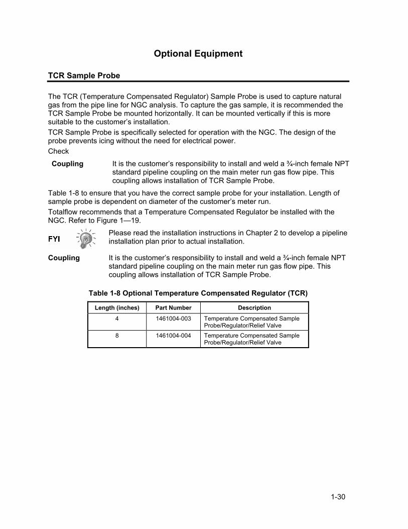
1-30
Optional Equipment
TCR Sample Probe
The TCR (Temperature Compensated Regulator) Sample Probe is used to capture natural gas from the pipe line for NGC analysis. To capture the gas sample, it is recommended the TCR Sample Probe be mounted horizontally. It can be mounted vertically if this is more suitable to the customer’s installation. TCR Sample Probe is specifically selected for operation with the NGC. The design of the probe prevents icing without the need for electrical power. Check
Coupling It is the customer’s responsibility to install and weld a ¾-inch female NPT standard pipeline coupling on the main meter run gas flow pipe. This coupling allows installation of TCR Sample Probe.
Table 1-8 to ensure that you have the correct sample probe for your installation. Length of sample probe is dependent on diameter of the customer’s meter run. Totalflow recommends that a Temperature Compensated Regulator be installed with the NGC. Refer to Figure 1—19.
Please read the installation instructions in Chapter 2 to develop a pipeline installation plan prior to actual installation.
Coupling It is the customer’s responsibility to install and weld a ¾-inch female NPT standard pipeline coupling on the main meter run gas flow pipe. This coupling allows installation of TCR Sample Probe.
Table 1-8 Optional Temperature Compensated Regulator (TCR)
Length (inches) Part Number Description
4 1461004-003 Temperature Compensated Sample Probe/Regulator/Relief Valve
8 1461004-004 Temperature Compensated Sample Probe/Regulator/Relief Valve

1-31
3/4" NPT
GAS FLOW
SAMPLE PROBE
CUSTOMER INSTALLED COUPLING
PRESSURE GAUGE
OUTLET PORT 1/4" NPT
RELIEF VALVE
Figure 1—19 Temperature Compensated Regulator With Sample Probe
Continued on Next Page

1-32
TCR Sample Probe, Cont.
Location • Locate the pipeline coupling on gas meter run in close proximity to the NGC. This allows the stainless steel sample line, from sample probe to Chromatograph, to be as short as possible.
• The coupling should be mounted so probe can be installed horizontally or vertically on meter run pipe. This means the coupling should be mounted on either the top or the side of meter run pipe.
• Sample Probe should not be mounted at the ends of headers, dead “T’s”, large volume accumulators or other spots where gas is likely to be stagnant.
• Installation should allow probe to penetrate the center 1/3 of main gas meter run. This allows sufficient heat transfer with the flowing gas sample. Sample Probe inlet should be high enough to avoid sampling of liquids at bottom of the pipe.
• Sample Probe, must be installed where probe has access to the fastest flow of gas within the pipe.
• Sample Probe should be mounted a minimum of five pipe diameters from any device which could cause aerosols or significant pressure drops.
Other Considerations
• TCR Sample Probe line pressure should be as close to 1-atmosphere as possible to reduce sample transport lag times due to “Line pack”. Sample pressure at the NGC should be 15 ± 2 PSIG (103 ± 14 Kpa).
• To maintain this pressure at the NGC filters, it may be necessary to increase TCR Sample Probe pressure to a value greater than 15 PSIG. Pressure is dependent on sample transport tubing length between the TCR Sample probe and Analyzer.
• Be sure to use tubing electrical isolators on sample tubing when connected to pipelines that are not isolated from cathodic protection.
VGA Display
The Display board provides a ¼ panel VGA monochromatic display to monitor the process and results. It also provides 6 magnetic switches to allow a user to navigate through various screens of data and control the processes (Stop operation, start operation and calibrate). If the NGC is configured with the front panel display, available screens and user defined screens may be navigated using the Display Magnet (Part No. 1801755-001). The optional VGA Display features: • ¼ panel VGA Display Circuit Board • 2 LED Status Indicators, user programmable (default Left LED- Flashing light indicates a
Fault alarm, solid light indicates a Warning alarm. Right LED- Solid light indicates unit is NOT in Auto run mode.)
• User interface, with Hall-Effect magnet navigation, for monitoring NGC8200 operation. Figure 1—20 shows the flow of information accessible through the display.
Continued on Next Page

1-33
VGA Display, Cont.
C3 1.00000IC4 0.29800NC4 0.29900NEO 3.40000IC5 0.40000NC5 0.40000C6+ 0.03000N2 2.38000C1 89.69300CO2 1.00000C2 5.00000
Dry Btu 1055.03250Sat. Btu 1037.54830Rel. Density 0.62388Compress 0.99763UnNorm 96.90860
C3 1.00390IC4 0.29863NC4 0.30004NEO 0.10078IC5 0.10214NC5 0.10171C6+ 0.02769N2 2.37627C1 89.70186CO2 0.99191C2 4.99506
Dry Btu 1055.25650Sat. Btu 1037.76810Rel. Density 0.62410Compress 0.99763UnNorm 97.16250
Figure 1—20 Optional NGC VGA Display Screens
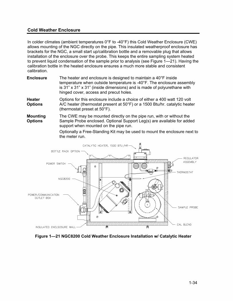
1-34
Cold Weather Enclosure
In colder climates (ambient temperatures 0°F to -40°F) this Cold Weather Enclosure (CWE) allows mounting of the NGC directly on the pipe. This insulated weatherproof enclosure has brackets for the NGC, a small start up/calibration bottle and a removable plug that allows installation of the enclosure over the probe. This keeps the entire sampling system heated to prevent liquid condensation of the sample prior to analysis (see Figure 1—21). Having the calibration bottle in the heated enclosure ensures a much more stable and consistent calibration.
Enclosure The heater and enclosure is designed to maintain a 40°F inside temperature when outside temperature is -40°F. The enclosure assembly is 31” x 31” x 31” (inside dimensions) and is made of polyurethane with hinged cover, access and precut holes.
Heater Options
Options for this enclosure include a choice of either a 400 watt 120 volt A/C heater (thermostat present at 50°F) or a 1500 Btu/hr. catalytic heater (thermostat preset at 50°F).
Mounting Options
The CWE may be mounted directly on the pipe run, with or without the Sample Probe enclosed. Optional Support Leg(s) are available for added support when mounted on the pipe run. Optionally a Free-Standing Kit may be used to mount the enclosure next to the meter run.
C
Figure 1—21 NGC8200 Cold Weather Enclosure Installation w/ Catalytic Heater

1-35
Sample Conditioning Modules
For some NGC installations, it may be necessary to install an optional Sample System Conditioning Module to compensate for non-ideal natural gas samples. These optional modules are pre-engineered to provide various levels of protection and bypass flows (see Figure 1—22). All of the Sample Conditioning Modules include a level of particulate protection, and come in two flow sizes, 50CC (2102023-xxx) and 450CC (2102024-xxx) per minute. For installations where the gas is ideal and the Sample Probe is located less that 10’ from the NGC, no Sample Conditioning Module is required.
Gas Types You can select from one of four Sample Conditioning Modules for installations whose gas samples do not meet the ideal clean and dry conditions. The following definitions define what is meant by the condition of natural gas to be sampled. • Clean Gas is defined as having no particles larger than one micron and
no more than one milligram of solids per cubic meter of gas. • Dry Gas is defined as having no more than seven pounds of water per
million cubic feet of gas. Gas has less than 0.1 PPM of liquid at the coldest ambient condition expected at the coldest point in the system. The liquid can be water, oil, synthetic lubrication, glycol, condensed sample or any other non vapor contaminate.
• Stable Gas is a vapor containing less than 0.1 PPM of liquid when vapor is cooled to 18.3°F (10°C) below the coldest ambient temperature possible at any point in the system.
Figure 1—22 Available Sample Conditioning Modules
Continued on Next Page

1-36
Sample Conditioning Modules, Cont.
2102023-001 Designed for clean, dry, stable gas, with minor amounts of particulate contamination, where the sample point is more than 10’ (3m) and less than 50’ (15m) from the NGC and the customer guarantees that upset conditions, compressor failure, or other problems will never occur. It is also suitable where a high quality sampling system already exists. NGC bypass flow is expected to be 10cc/min. System features: • 2 micron Filter
2102023-002 Designed for clean, stable gas sample point distances greater than 10’ (3m) and less than 50’ (15m) and containing minor amounts of liquids such as glycol, compressor oil, or water. This system will also handle minor amounts of particulate contamination. System features: • 2 micron Filter • Liquid/Vapor Separator
2102024-001 Designed for sample point distances greater than 10’ (3m) and less than 150’ (50m) with known particulate and liquid contamination. For stable gas samples containing pipe scale and other solid contaminates and possibly minor amounts of liquid contamination. System features: • Particulate/Coalescing Filter • Liquid/Vapor Separator
2102494-001 Designed for sample point distance greater than 50’ (15m) and less than 150’ (50m). The sample gas is known to contain particulate and liquid contamination with a good probability of line flooding in upset conditions, enough at times to overflow the coalescer (A+ Avenger) filter. Also has a Genie membrane for liquid rejection and a Genie liquid shut off to be used when liquid carry over would harm the chromatograph if it was introduced as a sample. This model contains a liquid shut off to protect the GC. The liquid shut off resets itself when liquids are no longer present. • Particulate/Coalescing Filter • Liquid/Vapor Separator
Mounting Brackets
Two Sample Conditioning System Mounting Brackets are available, a single stream bracket (see Figure 1—23) or a multiple stream bracket (Figure 1—24)for up to 3 modules. See Figure 1—25 and Figure 1—26 for installed dimensions.
Continued on Next Page

1-37
Sample Conditioning Modules, Cont.
Figure 1—23 Single Stream Sample Conditioning Assembly
Figure 1—24 Multiple Stream Sample Conditioning Assembly
Continued on Next Page
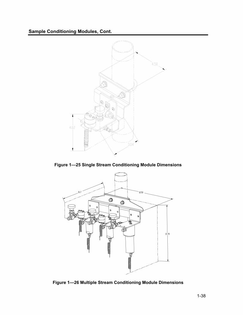
1-38
Sample Conditioning Modules, Cont.
Figure 1—25 Single Stream Conditioning Module Dimensions
Figure 1—26 Multiple Stream Conditioning Module Dimensions

1-39
Security Seal
For some NGC installations, it may be desirable to attach a Security Seal on the enclosure front and rear End Caps. To accommodate seal, please note the holes located in the tab located on each End Cap (See Figure 1—27).
Customer Supplied Materials
• 1 ea. Security Wire Seal • Seal Press
Figure 1—27 NGC End Cap Tabs for Security Seal
Instructions
Step Procedure
1. Insert Security Wire through holes located on End Cap Tabs.
2. Bring ends together and insert through holes in Security Seal (see Figure 1—28).
3. Use Seal Press to compress seal into Wire. Ensure that wire is firmly captured inside seal.
Figure 1—28 Security Wire with Seal

1-40
Optional Equipment Unit
If optional OEU Enclosure is used, it may be configured to include other options, including, but not limited to a battery pack to provide power to the NGC, communication equipment, solar power charger and additional I/O. Two enclosures are commonly used for the NGC installations, the 6470 OEU Enclosure and the 6770 OEU enclosure. The 6470 installation will be for AC to DC or DC sites requiring communication equipment. There is no battery backed option in this installation. The 6770 enclosure supports battery backed3 operation for the NGC, AC to DC Power or DC to DC Power and communication equipment. The XFC/XRC electronic board provides a battery charger/regulator for the system. Following local codes for installation, these units would normally be located in a Division 2 or General Purpose area. The units may be mounted on a 2” pipe, or mounted on a flat surface, such as a wall.
6470 OEU The 6470 can accommodate the following equipment: • Power Supply Kit for 6470
120VAC/12VDC power supply (2018554-001) 240VAC/12VDC power supply (2018554-002) 24VDC/12VDC DC to DC converter (2018554-003)
6770 OEU The 6770 enclosure can accommodate the following: • Power Supply Kit for 6713/14
120VAC/12VDC power supply (2017493-001) 240VAC/12VDC power supply (2017493-002) 24VDC/12VDC DC to DC converter 2015440-005)
• XFC/XRC-6413 Flow Computer XFC/XRC onboard battery charger will be used
• Battery Options 1 each 26/30AH battery
• Communications shelf for radio/modem
3 Autonomy measured in hours.

1-41
Explosion Proof Power Supply for 115/230VAC to 12 VDC
For installations requiring an Explosion Proof Power Supply, Totalflow provides two power supplies (115VAC and 230VAC to 12VDC) that meet these requirements and are housed in explosion proof enclosures.
Enclosure The custom designed explosion proof enclosure consists of a square shaped cast aluminum housing, powder coated, with top explosion proof threaded cap for access to internal components.
Enclosure, Cont.
The top cap has precision engineered threading and is susceptible to damage if treated roughly. Top cap is water tight, corrosion resistant and NEMA 4X rated. Unauthorized removal of the cap is protected with a Hex Socket set screw on cap.
AC POWER SUPPLY
Figure 1—29 Explosion Proof AC Power Supply

1-42
BBBlllaaannnkkk PPPaaagggeee

2-1
Chapter 2 Installation
Overview
This Chapter provides information for field installation of the NGC and optional equipment. After completing the procedures within this Chapter, the NGC will be ready for Start-up.
The installation instructions in this Chapter are to be performed only when the area is known to be Non-hazardous.
It is highly recommended that you thoroughly read this Chapter to establish an installation plan. Also, before you begin, refer to the wiring diagrams delivered with the new NGC. You may store these under the tab “Drawings” in the back of this manual.
What this Means
Installation instructions that feature this Icon, are applicable ONLY when the installation involves a Cold Weather Enclosure (CWE). All other instructions may or may not be applicable.
Highlights This Chapter covers the following topics:
Topic See Page Unpacking & Inspection 2-6 Sample Probe Installation 2-7 Stand Alone Installation 2-9 Freestanding Cold Weather Enclosure Installation 2-9 Pipe Mounted Cold Weather Enclosure Mounting Kit 2-11 Optional Support Leg Kit installation 2-15 Sample Probe Access Cover Installation 2-17 Pipe Saddle Installation 2-18 Shelf Installation 2-19 Cold Weather Enclosure (CWE) Mounting Plate 2-20 NGC Installation 2-22 Sample Conditioning Module Installation 2-23 Sample Line Connections 2-25 Sample Line(s) to NGC inside of Cold Weather Enclosure 2-27 CWE Optional Pwr/Comm Outlet Box Assembly 2-29 Carrier/Calibration Bottle Rack Installation on Meter Run 2-36 CWE Carrier Gas Bottle Rack Installation 2-37 Carrier Gas Regulator with Low Pressure Switch Installation 2-39 CWE Calibration Gas Bottle Installation 2-40 Calibration Gas Regulator - Low Pressure Switch Installation 2-41 Carrier Gas and Calibration Gas Connections 2-43
Continued on Next Page

2-2
Overview, Cont.
Topic, Cont. See Page Vent Line Connections 2-45 CWE Optional Catalytic Heater Installation 2-47 CWE Optional Electric Heater Installation 2-51 Optional Equipment Unit Installation 2-53 Optional AC/DC Explosion Proof Power Supply Installation 2-57 Optional AC/12VDC Power Supply Installation 2-60 Optional 24 VDC/12 VDC Power Converter 2-63 Optional OEU Battery Pack Installation 2-64 Optional 12V Solar Power Supply 2-67 DC Power Installation 2-69 Remote Communication Installation 2-70
The following procedures, unless otherwise stated, are applicable to all NGC units. The NGC is designed to be pipe mounted (see Figure 2—1). Optionally, a shelf mounting kit (see Figure 2—2) may be purchased for use in mounting the unit on a wall, inside or outside of a building or a mounting plate for use in the Optional Cold Weather Enclosure (see Figure 2—3).
Organization The following instruction sections are organized in the suggested installation order. Not all installation instructions will apply to your situation. For example, some procedures may vary when the installation does not require certain equipment.
Please note that where applicable, “typical” instructions are first and variations or “specialized” instructions, follow.
CALIBRATION GASCARRIER GAS
SAMPLE PROBE
NGC8200
Figure 2—1 Basic Meter Run Installation
Continued on Next Page

2-3
Overview, Cont.
FLANGE
WALL SHELF
MOUNTING PLATE
Figure 2—2 Typical Wall Shelf Mount Installation
C
Figure 2—3 Typical Cold Weather Enclosure with Electric Heater
Continued on Next Page

2-4
Overview, Cont.
Locating Area for Installation
The NGC is designed for mounting on main gas lines, 2-inch to 12-inch pipe sizes. Each type of installation is described within this Chapter. Be certain the installation site is clean and free of foreign debris that could affect NGC operation. The NGC should be located as close as possible to the Sample Probe installation point. This prevents the need for high gas flow rates through sample lines to assure analysis accuracy of current sample. If there is more than one stream being analyzed, locate the NGC in a central location to all Sample Probe points.
Installation The following information should help to determine the procedures to follow depending upon the type of installation: Meter Run Mount, Stand Alone, Shelf Mount located on a building wall, or Cold Weather Enclosure (CWE) Mounting for inclement climates.
Meter Run When mounting the unit directly on a Meter Run, the following installation procedures may be applicable. • Sample Probe Installation • Pipe Saddle Installation • NGC Installation • Sample Conditioning Module Installation • Sample Line Connections • Carrier/Calibration Bottle Rack Installation on Meter Run • Carrier Gas Regulator with Low Pressure Switch Installation • Calibration Gas Regulator - Low Pressure Switch Installation • Carrier Gas and Calibration Gas Connections • Vent Line Connections • Optional Equipment Unit Installation • Optional AC/DC Explosion Proof Power Supply Installation • Optional AC/12VDC Power Supply Installation • Optional 24 VDC/12 VDC Power Converter • Optional OEU Battery Pack Installation • Optional 12V Solar Power Supply • DC Power Installation
Stand Alone When mounting the unit on a free-standing pipe, the following installation procedures may be applicable. • Sample Probe Installation • Stand Alone Installation • NGC Installation • Sample Conditioning Module Installation • Sample Line Connections • Carrier/Calibration Bottle Rack Installation on Meter Run
Continued on Next Page

2-5
Overview, Cont.
Stand Alone, Cont.
• Carrier Gas Regulator with Low Pressure Switch Installation • Calibration Gas Regulator - Low Pressure Switch Installation • Carrier Gas and Calibration Gas Connections • Vent Line Connections • Optional Equipment Unit Installation • Optional AC/DC Explosion Proof Power Supply Installation • Optional AC/12VDC Power Supply Installation • Optional 24 VDC/12 VDC Power Converter • Optional OEU Battery Pack Installation • Optional 12V Solar Power Supply • DC Power Installation
Wall Shelf When mounting the unit on a shelf located on a building wall, the following installation procedures may be applicable. • Sample Probe Installation • Shelf Installation • NGC Installation • Sample Conditioning Module Installation • Sample Line Connections • Carrier/Calibration Bottle Rack Installation on Meter Run • Carrier Gas Regulator with Low Pressure Switch Installation • Calibration Gas Regulator - Low Pressure Switch Installation • Carrier Gas and Calibration Gas Connections • Vent Line Connections • Optional Equipment Unit Installation • Optional AC/DC Explosion Proof Power Supply Installation • Optional AC/12VDC Power Supply Installation • Optional 24 VDC/12 VDC Power Converter • Optional OEU Battery Pack Installation • Optional 12V Solar Power Supply • DC Power Installation
Cold Weather Enclosure
When mounting the unit inside of the Cold Weather Enclosure, the following installation procedures may be applicable. Please note that the Cold Weather Enclosure has several mounting options: Free Standing, Meter Run, and Meter Run with Support Leg(s). • Sample Probe Installation • Freestanding Cold Weather Enclosure Installation • Pipe Mounted Cold Weather Enclosure Mounting Kit • Optional Support Leg Kit installation • Sample Probe Access Cover Installation • Cold Weather Enclosure (CWE) Mounting Plate • NGC Installation
Continued on Next Page
2-6
Overview, Cont.
Cold Weather Enclosure, Cont.
• Sample Conditioning Module Installation • Sample Line Connections • Sample Line(s) to NGC inside of Cold Weather Enclosure • CWE Optional Pwr/Comm Outlet Box Assembly • CWE Carrier Gas Bottle Rack Installation • Carrier Gas Regulator with Low Pressure Switch Installation • CWE Calibration Gas Bottle Installation • Calibration Gas Regulator - Low Pressure Switch Installation • Carrier Gas and Calibration Gas Connections • Vent Line Connections • CWE Optional Catalytic Heater Installation • CWE Optional Electric Heater Installation • Optional Equipment Unit Installation • Optional AC/DC Explosion Proof Power Supply Installation • Optional AC/12VDC Power Supply Installation • Optional 24 VDC/12 VDC Power Converter • Optional OEU Battery Pack Installation • Optional 12V Solar Power Supply • DC Power Installation
The NGC8200 is certified for installation in Classified Hazardous locations. The heater and fittings in the Cold Weather Enclosure may not have the same ratings. All components of the installation, including accessories and fittings must be approved for the classification rating of the area of installation.
Unpacking & Inspection
Shipping Carton
Ensure that there is no external damage to the shipping container. If there is significant visible external damage contact your receiving group and report the damage to the trucking company for a Freight Damage Claim.
Unpacking The NGC is shipped in a specially designed shipping carton which contains the unit, mounting brackets, parts list and wiring and interconnect diagrams. Optional equipment is shipped in a separate carton. Carefully remove all internal and external packing material. Carefully remove all items from the box.
Bill of Lading After removing protective shipping cover from NGC, compare shipped contents with those listed on Bill of Lading. All items should match those on Bill of Lading.
Continued on Next Page
2-7
Unpacking & Inspection, Cont.
Inspection Examine internal NGC components for evidence of damage. Points of inspection are: • Visually inspect exterior of unit for dents, chipped paint, scratches,
damaged threads or broken glass plate, etc. • Physically inspect rear interior mounted circuit boards, cables, front
interior mounted circuit boards, for loose cables, boards, display and mounting screws etc.
• If applicable, inspect Calibration/Carrier gas bottles to be certain they are correct for the installation.
Damaged Components
If there is any damage, or if there are noticeable defects, notify your local Totalflow representative. Keep all shipping materials as evidence of damage, for carriers inspection. Totalflow will arrange for immediate repair or replacement. Telephone:
USA: (800) 442-3097 toll free International: 1-918-338-4880
Sample Probe Installation
If a Sample Probe has previously been installed, you may skip these instructions.
• Sample Probe Pipe coupling should be located on the top of the meter run but may be mounted vertical or horizontal.
• If the Sample Probe is to be located inside the Cold Weather Enclosure, it MUST be a vertical mounting on a horizontal pipe and be installed on the meter run prior to seating the Cold Weather Enclosure on the meter run.
Materials • ¾” NPT Pipe Coupling (previously installed) • Sample Probe (Configuration to be determined by the technician based
on installation and local codes.) • Teflon Tape • Or Customer supplied Pipe Dope (suitable for chromatography)
Instructions
Step Procedure
1. Shut down meter run and isolate from gas source. Be sure to use proper lockout and tagging procedures.
2. Bleed off gas from meter run.
3. Ensure installed mounting coupling is free from dirt and debris.
4. Ensure Sample Probe threads are free from dirt and debris.
Continued on Next Page

2-8
Sample Probe Installation, Cont.
Step Procedure, Cont.
5. Using Teflon tape or Pipe Dope, wrap or cover NPT threads of Sample Probe (see Figure 2—4).
6. Insert gas probe into pipeline coupling (see Figure 2—5).
7. Using the correct tool, tighten probe. Securely tighten so there is no gas leakage. DO NOT OVER TIGHTEN.
8. Install Shut-off valve on secondary side of Sample Probe if desired.
THREADED NECK 3/4" NPT.
PRESSURE RELIEF VALVE
PRESSURE GUAGE
1/4" OUTLET PORT
Figure 2—4 Sample Probe
3/4" NPT
GAS FLOW
SAMPLE PROBE
CUSTOMER INSTALLED COUPLING
PRESSURE GAUGE
OUTLET PORT 1/4" NPT
RELIEF VALVE
Figure 2—5 Sample Probe Insertion

2-9
Stand Alone Installation
If you will be installing an NGC using the Pipe Saddle Mounting Kit, use this procedure to install the Pipe Saddle. Before you begin, review the procedure and the materials required for installation.
Material Not Supplied
• One 2” Pipe with Flange • One 2” Pipe Coupling or • One 2” Mounting Pipe (Installed). Length dependant upon final overall
NGC desired height.
Optional equipment may be ordered from Totalflow.
Instructions
Step Procedure
1. Select a location to install Mounting pipe, that allows easy user access and is close to the Sample Probe. Lines should be as short as possible.
2. Install Mounting Pipe being careful to ensure pipe is vertically aligned.
3. Screw 2” Pipe Coupling onto top of Mounting pipe.
4. Screw Optional Mounting Flange Pipe into top of Pipe Coupling.
Continue to the “NGC Installation” instructions.
Method of installation must be consistent with customer’s company policy.
Freestanding Cold Weather Enclosure Installation
If your installation includes a Freestanding Cold Weather Enclosure, follow these instructions, otherwise skip to the next section.
Materials • 4 ea. ½-13 x 1 ¼ SST Bolt • 4 ea. ½ SST Flat Washer • 4 ea. ½” SST Split Washer • 1 ea. Stand
The following steps will typically require two people.
Continued on Next Page

2-10
Freestanding Cold Weather Enclosure Installation, Cont.
Instructions
Step Procedure
1. Stand is made symmetrical, so top and bottom are identical. Locate stand base on a flat, stable, surface.
2. Set enclosure on top of stand, oriented as shown in Figure 2—6.
3. Place a split washer, then a flat washer on one of the 1 ¼” Bolts and insert through bolt hole located in the angle iron into the outermost corner of the enclosure (see Figure 2—7).
4. Move channel Nut into position so that Bolt will screw into Nut. Screw Bolt into Nut, but do not tighten.
5. Repeat for all other corners.
6. Position enclosure on stand, centered front to back as desired and tighten all Bolts.
7. Foot Plate mounting holes are pre-drilled for mounting to a pad. Hardware to be supplied by customer.
Figure 2—6 Typical CWE Stand Mount Installation
Continued on Next Page

2-11
Freestanding Cold Weather Enclosure Installation, Cont.
Figure 2—7 CWE Mounting Hardware
Pipe Mounted Cold Weather Enclosure Mounting Kit
If your installation includes a Pipe Mounted Cold Weather Enclosure, follow these instructions as well as the Optional Support Leg instructions if applicable, otherwise continue to the next applicable set of instructions.
Materials • 4 ea. ½” -13 x 1 ¼ SST Bolt • 4 ea. ½” SST Flat Washer • 4 ea. ½” SST Split Washer • 2 ea. 2 ½” x ¼” 43” Steel Angle Iron
May be used in conjunction with optional Support Leg Kit. See Support Leg installation procedures next in this chapter.
Instructions
Step Procedure
1. Set two pieces of angle iron (see Figure 2—8) on bottom of upside down enclosure, being sure the side with the holes is facing the bottom of the enclosure and the solid sides of the angle iron are facing each other. Angle iron should be spaced so that the diameter of the pipe will fit in between.
2. Place a split washer, then a flat washer on one of the 1 ¼” Bolts (see Figure 2—9).
Continued on Next Page

2-12
Pipe Mounted Cold Weather Enclosure Mounting Kit, Cont.
(2 1/2)STK
.501.12
4.12 34.000
43.00
1.00
1.25
BOLT HOLES
.87.87
CHAIN HOLE
CHAIN RETAINERMOUNTING HOLE
ADJUSTMENTASSEMBLY HOLE
Figure 2—8 Mounting Brackets
(31.00)
Figure 2—9 Mounting Hardware Installation
Continued on Next Page
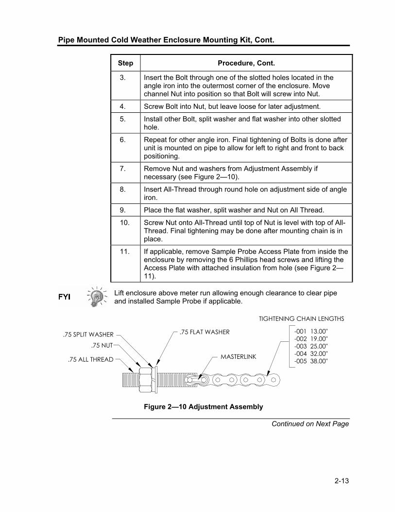
2-13
Pipe Mounted Cold Weather Enclosure Mounting Kit, Cont.
Step Procedure, Cont.
3. Insert the Bolt through one of the slotted holes located in the angle iron into the outermost corner of the enclosure. Move channel Nut into position so that Bolt will screw into Nut.
4. Screw Bolt into Nut, but leave loose for later adjustment.
5. Install other Bolt, split washer and flat washer into other slotted hole.
6. Repeat for other angle iron. Final tightening of Bolts is done after unit is mounted on pipe to allow for left to right and front to back positioning.
7. Remove Nut and washers from Adjustment Assembly if necessary (see Figure 2—10).
8. Insert All-Thread through round hole on adjustment side of angle iron.
9. Place the flat washer, split washer and Nut on All Thread.
10. Screw Nut onto All-Thread until top of Nut is level with top of All-Thread. Final tightening may be done after mounting chain is in place.
11. If applicable, remove Sample Probe Access Plate from inside the enclosure by removing the 6 Phillips head screws and lifting the Access Plate with attached insulation from hole (see Figure 2—11).
Lift enclosure above meter run allowing enough clearance to clear pipe and installed Sample Probe if applicable.
.75 ALL THREAD
.75 NUT
.75 SPLIT WASHER .75 FLAT WASHER
MASTERLINK
-001 13.00"-002 19.00"-003 25.00"-004 32.00"-005 38.00"
TIGHTENING CHAIN LENGTHS
Figure 2—10 Adjustment Assembly
Continued on Next Page
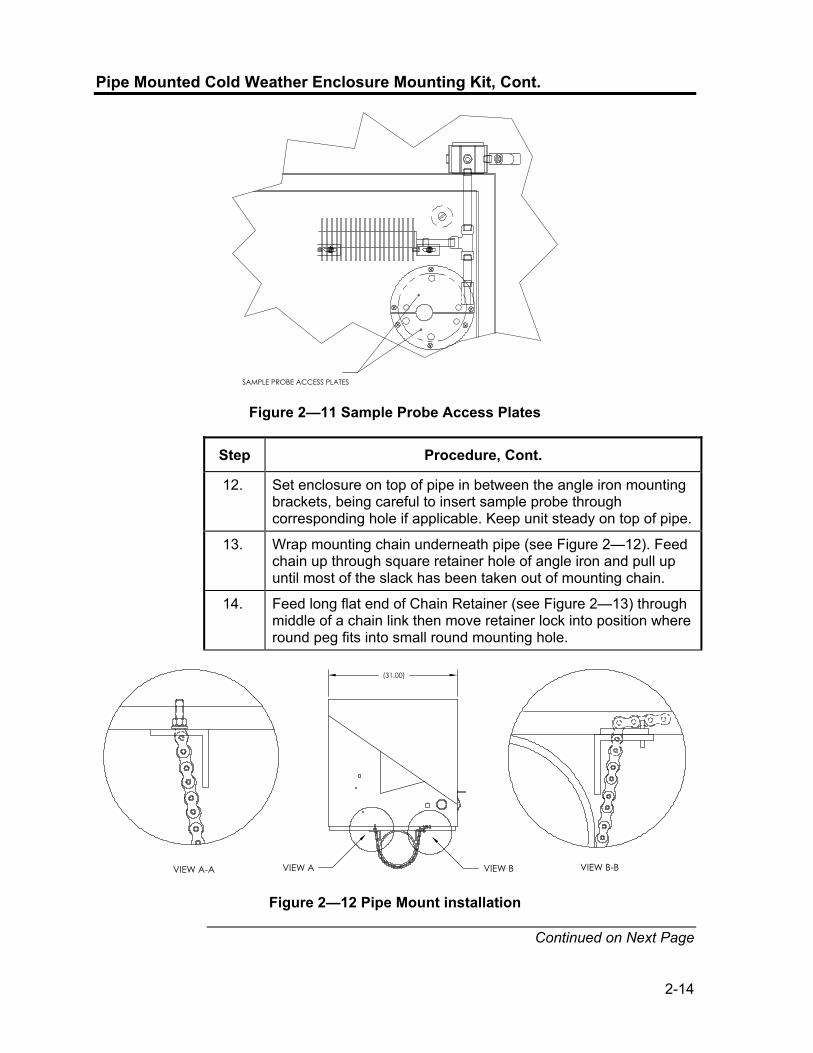
2-14
Pipe Mounted Cold Weather Enclosure Mounting Kit, Cont.
SAMPLE PROBE ACCESS PLATES
Figure 2—11 Sample Probe Access Plates
Step Procedure, Cont.
12. Set enclosure on top of pipe in between the angle iron mounting brackets, being careful to insert sample probe through corresponding hole if applicable. Keep unit steady on top of pipe.
13. Wrap mounting chain underneath pipe (see Figure 2—12). Feed chain up through square retainer hole of angle iron and pull up until most of the slack has been taken out of mounting chain.
14. Feed long flat end of Chain Retainer (see Figure 2—13) through middle of a chain link then move retainer lock into position where round peg fits into small round mounting hole.
(31.00)
VIEW A-A VIEW B-BVIEW BVIEW A
Figure 2—12 Pipe Mount installation
Continued on Next Page
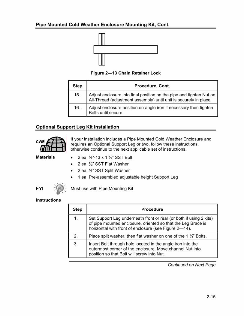
2-15
Pipe Mounted Cold Weather Enclosure Mounting Kit, Cont.
Figure 2—13 Chain Retainer Lock
Step Procedure, Cont.
15. Adjust enclosure into final position on the pipe and tighten Nut on All-Thread (adjustment assembly) until unit is securely in place.
16. Adjust enclosure position on angle iron if necessary then tighten Bolts until secure.
Optional Support Leg Kit installation
If your installation includes a Pipe Mounted Cold Weather Enclosure and requires an Optional Support Leg or two, follow these instructions, otherwise continue to the next applicable set of instructions.
Materials • 2 ea. ½”-13 x 1 ¼” SST Bolt • 2 ea. ½” SST Flat Washer • 2 ea. ½” SST Split Washer • 1 ea. Pre-assembled adjustable height Support Leg
Must use with Pipe Mounting Kit
Instructions
Step Procedure
1. Set Support Leg underneath front or rear (or both if using 2 kits) of pipe mounted enclosure, oriented so that the Leg Brace is horizontal with front of enclosure (see Figure 2—14).
2. Place split washer, then flat washer on one of the 1 ¼” Bolts.
3. Insert Bolt through hole located in the angle iron into the outermost corner of the enclosure. Move channel Nut into position so that Bolt will screw into Nut.
Continued on Next Page

2-16
Optional Support Leg Kit installation, Cont.
(31.00)
22.75TO
37.00
Figure 2—14 Optional Support Leg Overview
Must use with Pipe Mounting Kit
Instructions
Step Procedure
4. Screw Bolt into Nut, but leave loose for later adjustment. Repeat for other corner.
5. If installing two Support Legs, repeat for other angle iron. Final tightening of Bolts may be done after support leg(s) are in desired positioned on a flat stable surface.
6. Loosen Adjustment Handle and drop Leg Foot down and retighten Adjustment Handle.
7. Foot Plate mounting holes are pre-drilled for mounting to a pad. Hardware to be supplied by customer.
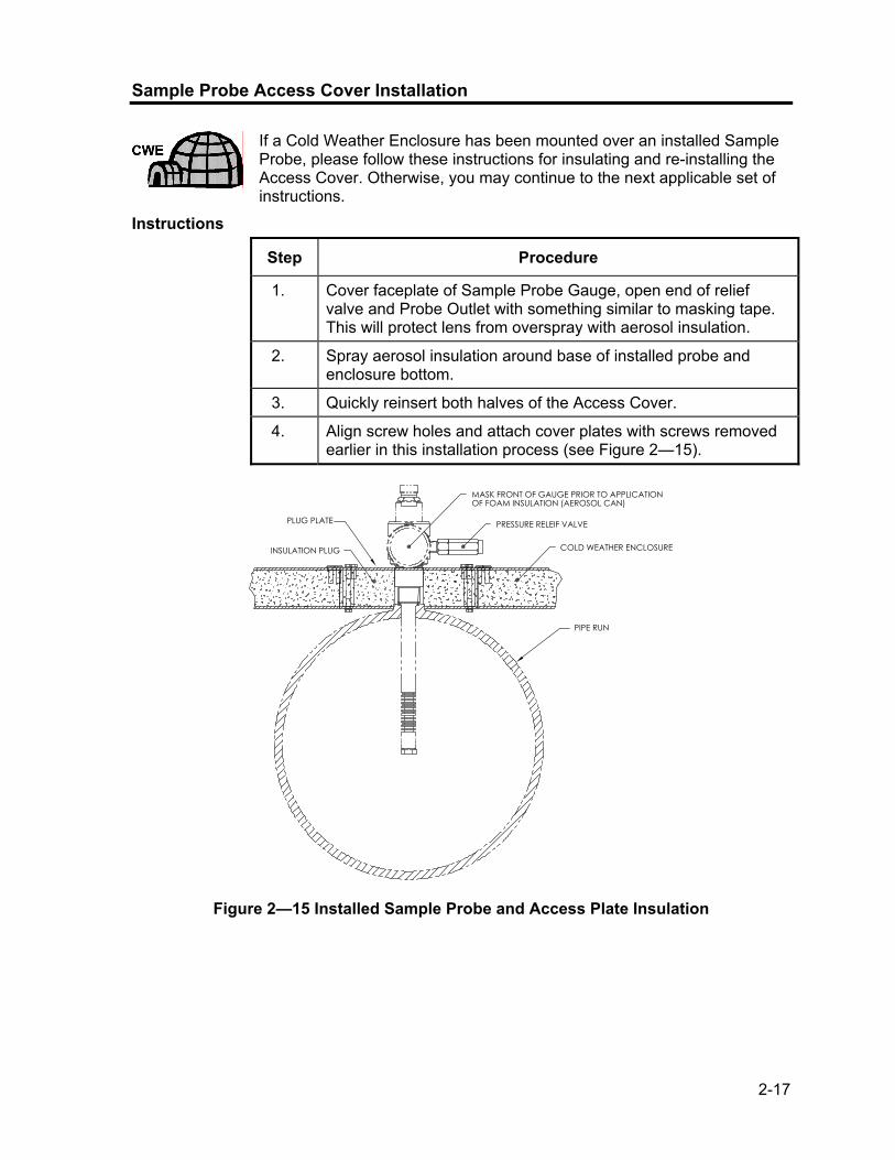
2-17
Sample Probe Access Cover Installation
If a Cold Weather Enclosure has been mounted over an installed Sample Probe, please follow these instructions for insulating and re-installing the Access Cover. Otherwise, you may continue to the next applicable set of instructions.
Instructions
Step Procedure
1. Cover faceplate of Sample Probe Gauge, open end of relief valve and Probe Outlet with something similar to masking tape. This will protect lens from overspray with aerosol insulation.
2. Spray aerosol insulation around base of installed probe and enclosure bottom.
3. Quickly reinsert both halves of the Access Cover.
4. Align screw holes and attach cover plates with screws removed earlier in this installation process (see Figure 2—15).
PIPE RUN
OF FOAM INSULATION (AEROSOL CAN)MASK FRONT OF GAUGE PRIOR TO APPLICATION
PRESSURE RELEIF VALVE
COLD WEATHER ENCLOSURE
PLUG PLATE
INSULATION PLUG
Figure 2—15 Installed Sample Probe and Access Plate Insulation

2-18
Pipe Saddle Installation
If you will be installing an NGC using the Pipe Saddle Mounting Kit, use this procedure to install the Pipe Saddle. Before you begin, review the procedure and the materials required for installation. The optional Pipe with Flange may be used in installations requiring additional stability.
Material Not Supplied
• 1 ea. Pipe Saddle • 1 ea. 2” Mounting Pipe. Length dependant upon final overall NGC
desired height. • 1 ea. 2” Pipe with Flange (Optional) • 1 ea. 2” Pipe Coupling( Optional)
Optional equipment may be ordered from Totalflow.
Instructions
Step Procedure
1.
Position Pipe Saddle on meter run. Select a location that allows easy user access and is close to the Sample Probe. Lines should be a short as possible.
2. Temporarily attach Saddle on meter run pipe using U-Bolt and associated hardware (see Figure 2—16).
3.
Screw one end of the 2” pipe into Saddle Flange on Pipe Saddle until “wrench tight”. Place level against pipe and vertically align, adjusting saddle, until vertical alignment is achieved.
4. After vertical alignment, securely tighten saddle mounting Bolts.
5. If configuration includes the optional Pipe with Flange, screw 2” Pipe Coupling onto top of Mounting Pipe.
6. Screw Optional Mounting Pipe with Flange into top of Pipe Coupling.
Continue to the “NGC Installation” instructions. Method of installation must be consistent with customer’s company policy.
Continued on Next Page

2-19
Pipe Saddle Installation, Cont.
METER RUN"U" MOUNTING BOLT
SADDLE
OPTIONAL MOUNTING FLANGE PIPE
2" PIPE COUPLING
Figure 2—16 Typical Pipe Saddle Installation
Shelf Installation
If your installation calls for the NGC Shelf Mounting Kit, use this procedure to mount the shelf, otherwise continue to the next applicable instructions. Before you begin, review the procedure and the materials required for installation.
Materials • 4 ea. ¼” x 20 1” SST Hex Head Machine Screws • NGC Mounting Shelf with Flange • 1 ea. 2” Mounting Pipe. Length dependant upon final overall NGC
desired height. • 1 ea. 2” Pipe with Flange (Optional) • 1 ea. 2” Pipe Coupling (Optional)
Instructions
Step Procedure
1. Locate wall position where NGC is to be mounted. The shelf should be positioned, high enough on the wall, so all components are accessible to service personnel. Shelf should be installed in close proximity to the installed Sample Probe.
2. Mount the shelf to the wall, being careful to keep level) using four ¼ x 20, 1-inch SST Hex Head machine screws in each of the four shelf mounting holes. Refer to Figure 2—17.
3. Screw one end of 2” Mounting Pipe into flange on mounting plate until “wrench tight”.
4. If configuration includes the optional Pipe with Flange, screw 2” Pipe Coupling onto top of Mounting Pipe.
5. Screw Optional Mounting Pipe with Flange into top of Pipe Coupling.
Continued on Next Page

2-20
Shelf Installation, Cont.
Continue to the “NGC Installation” instructions. Method of installation must be consistent with customer’s company policy.
OPTIONAL MOUNTING FLANGE PIPE
2" PIPE COUPLING
WALL SHELF
Figure 2—17 Shelf Installation
Cold Weather Enclosure (CWE) Mounting Plate
If you will be installing an NGC inside a Cold Weather Enclosure, use this procedure to install the mounting plate inside the enclosure, otherwise continue to the next applicable instructions. Before you begin, review the procedure and the materials required for installation.
Materials • Mounting Plate with Flange • 2” Pipe with Flange • 4 ea. 5/16” – 18 UNC X 1” Hex Head Screw • 4 ea. 5/16” x .575 x .078 SST Split Washer • 4 ea. 5/16” SST Flat Washer
Instructions
Step Procedure
1. Place Mounting Plate (see Figure 2—18) inside of the Cold Weather Enclosure, oriented so that each Bolt hole is aligned with the Mounting Tracks (see Figure 2—19).
2. Move Channel Spring Nuts into position underneath slotted mounting holes.
Continued on Next Page

2-21
Cold Weather Enclosure Mounting Plate, Cont.
Figure 2—18 NGC Mounting Plate
MOUNTING TRACKS
5/16"-18 CHANNEL SPRING NUTS
Figure 2—19 Cold Weather Enclosure Interior
Step Procedure, Cont.
3. Place split washer, then flat washer on one of the 5/16” screws and insert through one of the 4 holes on the mounting base, into the corresponding Channel Nut. Do not tighten until unit is in final position.
4. Repeat for other 3 screws/channel Nuts.
5. Screw 2” pipe into flange on mounting plate until “wrench tight”.
Continue to the “NGC Installation” instructions. Method of installation must be consistent with customer’s company policy.

2-22
NGC Installation
Once the mounting system has been installed, either the Saddle Mounting Kit, the Shelf Mounting Kit, or the Mounting Plate located inside the Cold Weather Enclosure, these instructions should be followed to install the NGC onto the mounting pipe. Before you begin, review the procedure and the materials required for installation.
Materials • Installed Mounting Pipe • 4 ea. 5/16”Hex Socket Screws (Optional for use with Mounting Pipe
with Flange kit) • NGC
Instructions
Step Procedure
1. Position NGC on top of 2” pipe stand (see Figure 2—20), in close approximation to correct orientation.
2. If installation has the Optional Mounting Pipe with Flange, ensure screw holes in upper flange align with holes located in the NGC neck bottom (see Figure 2—21). • For installation inside of a Cold Weather Enclosure, the front
display of the unit would normally face left, with the Feed-Through Assembly facing the front opening of the enclosure. This allows screen visibility, access to the Feed-Through Assembly and Termination Panel located in the rear of the housing.
• For Shelf Mounted units, the unit would be oriented with the Feed-Through Assembly also facing forward. Sufficient clearance is required when mounted near an inside corner.
Otherwise, continue to the next step.
3. Secure in place by tightening the Hex Socket Set Screw located in the neck of the unit using a 1/8” Hex Wrench.
PIPE RUN MOUNTED
PIPE SADDLE
WALL SHELF MOUNTING
WALL SHELF
STAND-ALONE PIPE MOUNTED
COLD WEATHER ENCLOSURE MOUNTED
2" MOUNTING PIPE
CWE MOUNTING
PLATE
OPTIONAL MOUNTING PIPE
W/FLANGE
Figure 2—20 NGC Mounting
Continued on Next Page

2-23
NGC Installation, Cont.
Figure 2—21 NGC Optional Mounting Flange Pipe
Instructions
Step Procedure, Cont.
4. If installation has Optional Mounting Flange Pipe, insert Hex Socket Screw through hole in the welded flange into the neck bottom of unit and tighten using ¼” Hex Wrench. Repeat for all screws.
5. If installation has Optional Mounting Flange Pipe, small adjustments may be made to orientation, by applying additional pressure to mounting pipe with pipe wrench, tightening mounting pipe into shelf mounted flange or pipe saddle flange. Otherwise, loosen Hex Socket Set Screw, rotate unit and retighten.
When positioning the unit, you should take into consideration the mounting of the Sample Conditioning System, Conduit locations and access to the rear end cap of the unit.
Sample Conditioning Module Installation
Materials • Installed NGC • Single or Multiple Module Mounting Kit • 1 ea. .312 x 2.5 x 3.62 x 1.5 U-Bolt • 2 ea. 5/16” SST Split Washer • 2 ea. 5/16” SST Flat Washer • 2 ea. 5/16-18 SST Lock Nut • Sample Conditioning Module(s) and hardware
Continued on Next Page

2-24
Sample Conditioning Module Installation, Cont.
Mounting Kits Both Sample Conditioning Module Mounting Brackets are installed identically. The Single Module Bracket will hold a single stream Sample Conditioning Module, while the Multiple Module Bracket will hold up to 3 Sample Conditioning Modules.
Instructions
Step Procedure
1. On Sample Conditioning Module, align mounting holes to corresponding holes in bracket. Insert Bolt through hole in bracket, from front to back through mounting hole in module (see Figure 2—22). Place split washer, then flat washer on Bolt. Screw Nut onto end of Bolt, finger tight. Repeat for second mounting Bolt. Tighten both Nuts.
2. Repeat for all additional Modules.
3. Straddle mounting pipe with U-Bolt and insert threaded ends through holes located in Bracket, so that Bracket back fits flat against pipe and Module Mounting Lip sets away from pipe (see Figure 2—23).
4. Place the flat washer, then a split washer on end of U-Bolt. Screw Nut onto end of Bolt, finger tight.
5. Repeat Step 4 for other side of U-Bolt.
6. Move bracket into position underneath NGC, being careful to allow clearance for Sample Conditioning Module(s).
7. Tighten both Nuts.
Figure 2—22 Sample Conditioning Module Bracket
Continued on Next Page

2-25
Sample Conditioning Module Installation, Cont.
2" Pipe
U-Bolt
VIEW A-A
A A A A
B
B
VIEW B-B
SINGLE MODULE BRACKET MULTIPLE MODULE BRACKET 2 EA. 5/16-18 SST LOCKING HEX NUT2 EA. 5/16" SST FLAT WASHER2 EA. 5/16" SST SPLIT LOCK WASHER
Figure 2—23 Sample System Mounting Kits
Sample Line Connections
Following installation of the Sample Conditioning Module(s), the sample tubing from the Sample Probe to the Sample Conditioning System and NGC Feed-Through Assembly should be installed.
Materials • 1/8” SST Chromatography Grade Transport Tubing (Amount to be determined by technician based on distance from Sample Probe to Sample Conditioning Module and number of Sample Streams.
• 2 ea. Ferrule and Nut (for each sample stream) • 1 ea. ¼” NPT to 1/8” Reducer or other size as determined from Sample
Probe Output port (for each sample stream) • 1 ea. Sample Conditioning Module Transport Tubing (supplied with
Sample Conditioning Module). Instructions
Be certain ends of stainless steel tubing are open and not restricted.
Step Procedure
1. Locate sample input fitting on Sample Conditioning Module (see Figure 2—24).
2. Locate sample output fitting on installed Sample Probe.
3. Measure and cut SST Tubing to required length.
4. Make necessary bends in tubing to ease installation of the ferrule and Nut into Sample Conditioning Module Input Port.
Continued on Next Page
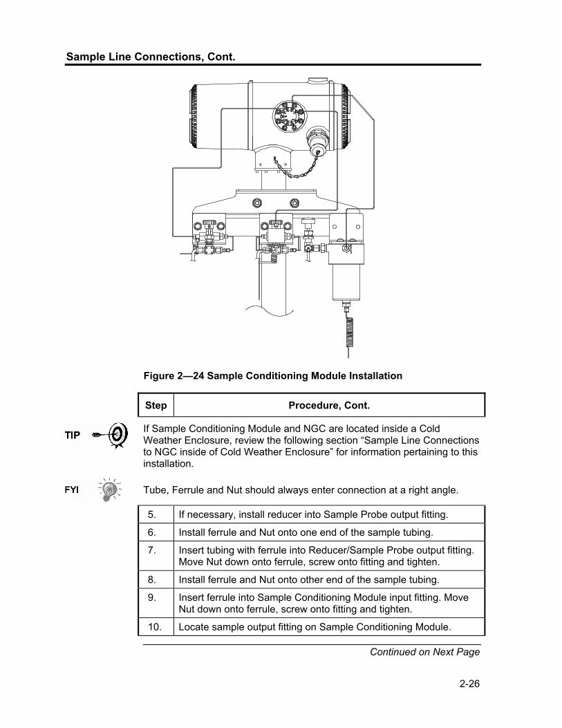
2-26
Sample Line Connections, Cont.
Figure 2—24 Sample Conditioning Module Installation
Step Procedure, Cont.
If Sample Conditioning Module and NGC are located inside a Cold Weather Enclosure, review the following section “Sample Line Connections to NGC inside of Cold Weather Enclosure” for information pertaining to this installation.
Tube, Ferrule and Nut should always enter connection at a right angle.
5. If necessary, install reducer into Sample Probe output fitting.
6. Install ferrule and Nut onto one end of the sample tubing.
7. Insert tubing with ferrule into Reducer/Sample Probe output fitting. Move Nut down onto ferrule, screw onto fitting and tighten.
8. Install ferrule and Nut onto other end of the sample tubing.
9. Insert ferrule into Sample Conditioning Module input fitting. Move Nut down onto ferrule, screw onto fitting and tighten.
10. Locate sample output fitting on Sample Conditioning Module.
Continued on Next Page

2-27
Sample Line Connections, Cont.
Step Procedure, Cont.
11. Locate sample input on NGC Feed-Through Assembly and remove sealing Screw.
Leave sealing screw in any unused ports. If unused stream ports are not sealed, moisture can enter the manifold which can damage the instrument and void warranty.
12. Make necessary bends in tubing to ease installation of the tubing into output fitting on Sample Conditioning Module, and ferrule and Valco Nut into input on NGC Feed-Through Assembly.
13. Insert tubing with ferrule into output fitting on Sample Conditioning Module. Move Nut down onto ferrule, screw onto fitting and tighten.
14. Remove plastic caps from Restrictor Coils, sealing screws from Feed-Through Column Vents and sealing screw from Sample Vent lines.
15. Purge air from the transport tubing by opening the shut-off valve located on the Sample Probe.
Be sure to follow requirements of national and local codes when performing this purge.
16. Insert tubing with ferrule into corresponding input port located on the NGC Feed-Through Assembly. Move Valco Nut down onto ferrule, screw into port and tighten.
17. Repeat for each Sample Stream.
DO NOT over tighten. After securing tubing, check for gas leaks.
Sample Line(s) to NGC inside of Cold Weather Enclosure
Sample Line(s) being installed to a unit located inside the Cold Weather Enclosure require making minute changes to the instructions listed for their installation. The following information and steps should be noted during the installation
Materials • Heat Trace Materials provided by customer for each additional stream • Aerosol Insulating Foam (supplied with enclosure)
Continued On Next Page

2-28
Sample Line(s) to NGC inside of Cold Weather Enclosure, Cont.
Instructions
Step Procedure
1. Please follow Heat Trace Manufacturer’s suggested installation instructions for applying Heat Trace equipment to additional Sample Streams.
2. Locate Sample Boot on side of Cold Weather Enclosure (see Figure 2—25).
3. Using instructions covered previously under “Sample Line Connections”, run Sample Line from Sample Probe through Sample Boot, to Sample Conditioning Module located below the NGC.
4. Repeat for each additional Sample Stream.
5. When Sample Line Connections are complete, apply aerosol insulating foam from inside the enclosure pointing toward the outside of boot, ensuring that the overspray falls outside the enclosure.
Figure 2—25 Sample Boot

2-29
CWE Optional Pwr/Comm Outlet Box Assembly
If installing the NGC inside a Cold Weather Enclosure, use this procedure to install the optional RS-232/RS-485/RS-422 Outlet Box (P/N 2102296-xxx) if required, otherwise continue to the next applicable instructions. Before you begin, review the procedure and the materials required for installation.
Materials • 1 ea. Outlet Box Assembly • 1 ea. Internal NGC Connection Assembly • 1 ea. Flexible Cable Assembly • 1 ea. DC Power Switch Box • 1 ea. Support Bracket
• 2 ea. 10-32 x ¾” SS Pan Head Screw, Phillips • 2 ea. #10 SST Flat Washer • 2 ea. #20 SST Split Washer • Materials for external wiring (to Outlet Box) not provided by Totalflow.
Quantities and materials to be determined by the technician based on installation and local codes.
Instructions
Step Procedure
1. Remove left side access plate, if so equipped, from enclosure (see Figure 2—26).
2. Gain access to rear Termination Panel of NGC by loosening the Countersunk Hex Socket Locking Set Screw in the rear end cap using a 1/16” Hex wrench, then unscrewing the end cap.
3. Remove Hub Plug from the bottom most Access Hub.
4. Beginning with the Internal Connection Assembly (see Figure 2—27), feed the 13” wire bundle (elbow end of assembly) through open hub. Continue to pull wire past terminations until the nipple fitting is in position to screw into Hub
Continued on Next Page

2-30
CWE Optional Pwr/Comm Outlet Box Assembly, Cont.
FLEXABLE CABLE
DC POWER SWITCH
OUTLET BOX ASSY
ACCESS OPENING
INTERNAL CONNECTION ASSY
Figure 2—26 CWE Access Panel Removed
OUTLET BOX ASSEMBLYDC POWER SWITCH INTERNAL NGC CONNECTION ASSEMBLYFLEXIBLE CABLE ASSEMBLY
Figure 2—27 Power Communication Outlet Box Assembly
Continued on Next Page

2-31
CWE Optional Pwr/Comm Outlet Box Assembly, Cont.
Step Procedure, Cont.
5. Moving assembly Clockwise screw nipple fitting into hub until assembly is tight and hanging straight down.
6. Feed other end of wire bundle through Flexible Cable Assembly, beginning at end with Sealing Gasket, until threads meet Conduit Seal.
7. Rotate the Flexible Cable Assembly Clockwise, screwing threads into Conduit Seal until tight. For explosion proof installation, a minimum of 5 threads engaged are required.
8. Feed wires through the small hole located near the Sample Boot in the lower front of the CWE
9. Remove cover from Outlet Box Assembly.
Remove Elbow Cap on Outlet Box Assembly to facilitate feeding the wrapped wire around the elbow.
10. Feed wires through Outlet Box elbow and out past the wiring panel, moving assembly up to the threaded end of the cable.
11. Begin threading the Outlet Box Assembly onto end of Flexible Cable Assembly, rotating entire Outlet Box Assembly Clockwise until tight and in a vertical position. For explosion proof installation, a minimum of 5 threads engaged are required.
12. Locate Support Bracket Mounting Holes on enclosure.
13. Place the split washer, then a flat washer on end of each screw.
14. Insert screw through mounting bracket and into hole on side of enclosure.
15. Using a Phillips Point Screwdriver, start screw into hole, but do not tighten.
16. Repeat Steps 13 through 15 for second screw.
17. Level bracket and tighten screws until snug.
18. Move Outlet Box Assembly down so that it rests on the Mounting Bracket (see Figure 2—28).
19. At the NGC Termination Panel, trim and strip wire ends.
20. Remove Power Field Termination J1 Connector from Termination Panel.
21. Using the Wiring Instructions in Figure 2—29, install each wire into the correct terminal and replace connector on board.
Continued on Next Page

2-32
CWE Optional Pwr/Comm Outlet Box Assembly, Cont.
NGC8200
INSULATED ENCLSOSURE WALL
MOUNTING BRACKET
FLEXABLE CABLE ASSEMBLYDC POWER SWITCH
OUTLET BOX ASSEMBLY
CONDUIT SEAL-TO BE COMPLETED BY CUSTOMER
Figure 2—28 Assembled Power/Communication Assembly
POWERD1
J1
(-)(+)
Figure 2—29 Power Wiring Diagram
Continued on Next Page

2-33
CWE Optional Pwr/Comm Outlet Box Assembly, Cont.
Step Procedure, Cont.
22. Trim and strip wire ends located in the external Outlet Box.
23. Remove Power Field Termination J3 Connector from Outlet Box Panel.
24. Using the Wiring Instructions in Figure 2—29, install each wire into the correct terminal and replace connector on board.
25. Remove DC Power Switch Box Cover.
26. Remove the switch mounting screws and remove the switch.
27. Cut a 3’ length of Power (+) wire.
Optionally, Communication wires may be run directly to the spare Conduit Hub located on the bottom of the Outlet Box Assembly. Follow requirements of national and local codes.
For the purpose of this manual, we will assume that communication wiring will be included with the power wiring in one conduit run.
28. Tape 3’ Power (+) wire, Ground and Communication wire ends together.
29. Feed through Conduit Hub located on the bottom of the DC Power Switch Box, past cover opening, around elbow and out.
30. Continue pulling wire until approximately 2’ of wire is extending out of the DC Power Switch Box.
Be careful to not pull 3’ Power (+) wire past the DC Power Switch Box opening.
31. Feed excess wire through 6” Nipple Fitting, Conduit Seal, 5” Nipple Fitting and out into Outlet Box opening. Pull sufficient wire to complete field wiring.
32. Remove Power Field Termination J4 Connector from Outlet Box Panel.
33. Using the Wiring Instructions in Figure 2—29, install power (+) and power (-) wires into the correct terminal pins and replace connector on board.
34. Holding wires, slide DC Power Switch box up to 6” nipple fitting on end out Outlet Box Assembly.
35. Slide Conduit Union onto end of nipple fitting and screw on.
36. Loosen terminal screws on DC Power Switch.
37. Using the Wiring Instructions in Figure 2—29, wire Power (+) to upper terminal screw and tighten.
Continued on Next Page

2-34
CWE Optional Pwr/Comm Outlet Box Assembly, Cont.
Step Procedure, Cont.
38. Bring new Power (+) wire into Power Switch Enclosure and pull short length out to allow wiring.
39. Using the Wiring Instructions in Figure 2—29, wire new Power (+) length to bottom terminal screw and tighten.
40. Re-install DC Power Switch into box.
41. Using the Wiring Instructions in Figure 2—30 (RS-232), Figure 2—31 (RS-485) or Figure 2—32 (RS-422), make field connections to plug NGC Termination Panel Com Port (s) , re-insert into corresponding connector in Termination Panel.
42. Using the Wiring Instructions in Figure 2—30 (RS-232), Figure 2—31 (RS-485) or Figure 2—32 (RS-422), make field connections to plug J1, re-insert into corresponding connector in Outlet Box.
43. Using the Wiring Instructions in Figure 2—29 (RS-232), Figure 2—31 (RS-485) or Figure 2—32 (RS-422), make field connections to plug J2, re-insert into corresponding connector in Outlet Box.
Communication wiring terminations inside the Power/Communication Outlet Box Assembly are pass-through connections, meaning that J1-pin 1 is associated with J2-pin 1. Therefore, pin outs may be user defined and wiring Instructions for this assembly are only suggestions.
External wiring and connections should be performed by person(s) qualified for the type and area of installation according to National and Local codes.
44. Following instructions included with unit, complete seal between DC Power Switch and Outlet Box Assembly.
Continued on Next Page

2-35
CWE Optional Pwr/Comm Outlet Box Assembly, Cont.
5
3
4
2
J8 COMM PORT 1
1
NGC 8200
RXDTXD
RTS
CTS
GND
8 8
10 10
9 9
11 11
12 12
6
7
8
9
1 2 3J9
2102080-XXX
3 3
5 5
4 4
6 6
7 7
1 1
2 2SW PWR
CO
MM
1C
OM
M 2
TERMINATION BOARD
5
3
4
2
J10 COMM PORT 2
1
6
7
8
9
1 2 3J11
RXDTXD
RTS
CTS
GNDSW PWR
Figure 2—30 Suggested RS-232 Wiring Instructions
5
3
4
2
J10 COMM PORT 2
1
6
7
8
9
BUS-BUS+
RRTS
GNDSW PWR
TERMINATION BOARDNGC 8200
2102080-XXX
1 2 3
J9
1 2 3
J11
5
3
4
2
J8 COMM PORT 1
1
BUS-BUS+
RRTS
GND
8 8
10 10
9 9
11 11
12 12
6
7
8
9
3 3
5 5
4 4
6 6
7 7
1 1
2 2SW PWR
CO
MM
1C
OM
M 2
Figure 2—31 Suggested RS-485 Wiring Instructions
Continued on Next Page

2-36
CWE Optional Pwr/Comm Outlet Box Assembly, Cont.
TERMINATION BOARD
5
3
4
2
J8 COMM PORT 1
1
NGC 8200
RXD+TXD -
TXD+
RXD-
GND
8 8
10 10
9 9
11 11
12 12
6
7
8
9
2102080-XXX
3 3
5 5
4 4
6 6
7 7
1 1
2 2SW PWR
CO
MM
1C
OM
M 2
5
3
4
2
J10 COMM PORT 2
1
6
7
8
9
RXD+TXD -
TXD+
RXD-
GNDSW PWR
1 2 3
J9
1 2 3
J11
Figure 2—32 Suggested RS-422 Wiring Instructions
Carrier/Calibration Bottle Rack Installation on Meter Run
The Carrier/Calibration Gas Bottle Rack is used to hold the Carrier and Calibration Gas Bottles on installations not using a Cold Weather Enclosure. A gas regulator should be installed on each gas bottle (see Figure 2—33). This Bottle Rack is not available through Totalflow, therefore the instructions are generalized.
Instructions
Step Procedure
1. Position Bottle Rack in close proximity to NGC.
2. Secure Rack to the pipe meter run with provided mounting hardware.
3. Install both Carrier and Calibration Gas bottles in the Rack.
4. Strap both bottles in Rack to prevent their falling.
Continued on Next Page

2-37
Carrier/Calibration Bottle Rack Installation on Meter Run, Cont.
CALIBRATIONGAS
CARRIERGAS
TO NGC
Figure 2—33 Carrier/Calibration Gas Bottle Rack Installation
CWE Carrier Gas Bottle Rack Installation
The Carrier Gas Bottle Rack is used to hold Carrier Gas Bottles and is installed on the back of the Cold Weather Enclosure. A gas regulator should be installed on each gas bottle (see Figure 2—34).
Materials • 1 ea. Bracket with Chain Assembly attached • 2 ea. 3/8”-16 x 5/8 SST Hex Head Bolt • 2 ea. 3/8” SST Split Washers • 2 ea. 3/8” SST Flat Washers
Instructions
Step Procedure
1. Place a split washer, then a flat washer on one of the 5/8” Bolts and insert through bolt hole located in the Bottle Rack Bracket into the corresponding hole located along the bottom edge of the enclosure and tighten (see Figure 2—35).
Enclosure hole contains a Captive Nut.
Continued on Next Page
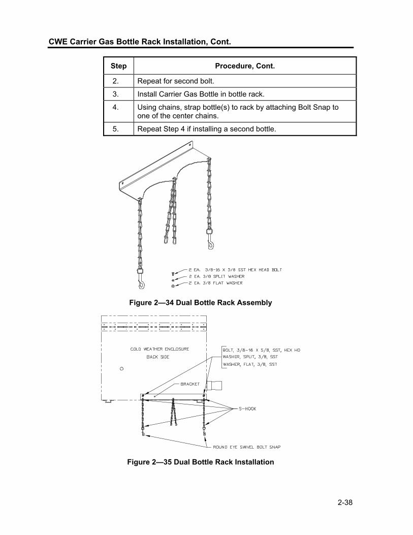
2-38
CWE Carrier Gas Bottle Rack Installation, Cont.
Step Procedure, Cont.
2. Repeat for second bolt.
3. Install Carrier Gas Bottle in bottle rack.
4. Using chains, strap bottle(s) to rack by attaching Bolt Snap to one of the center chains.
5. Repeat Step 4 if installing a second bottle.
Figure 2—34 Dual Bottle Rack Assembly
Figure 2—35 Dual Bottle Rack Installation

2-39
Carrier Gas Regulator with Low Pressure Switch Installation
The following instructions are valid for all installations.
Materials • Carrier Regulator Assembly (2017225-002) with Low Pressure Switch (see Figure 2—36)
• Installed Carrier Gas Bottle
These instructions assume that the Carrier Gas bottle has previously been installed.
Instructions
Step Procedure 1. Remove protective cap from High Pressure Inlet if required.
2. Insert Ferrule on Regulator High Pressure Inlet into Carrier Gas Bottle Outlet.
3. Screw Nut onto thread and tighten.
DO NOT connect Low Pressure Switch directly to the NGC without a Barrier.
4. Remove J2 field wiring connector from NGC Termination Panel located inside the rear of the enclosure (see Figure 2—37).
5. Using a small flat blade screw driver, loosen DI1 Pins 1 and 2.
6. Insert the Red wire into the (+) terminal (Pin 1).
7. Retighten Pin 1.
8. Insert the Black wire into the (-) terminal (Pin 2).
Figure 2—36 Carrier Gas Pressure Regulator with Relief Valve
Continued on Next Page

2-40
Carrier Gas Regulator with Low Pressure Switch Installation, Cont.
J2(-)(+) (-)(+) (-)(+) (-)(+)
INPUTS OUTPUTS1 1 22
DIGITAL I/0
NGC TERMINATION BOARD
BARRIER REQUIRED FOR ALL INSTALLATIONS OTHER THAN NON-HAZARDOUS
ASSYREGULATOR CARRIER
CYLINDER
Figure 2—37 Carrier Gas Low Pressure Switch Wiring Instructions
Step Procedure, Cont.
9. Retighten Pin 2.
10. Replace the termination connector in J2 board connector.
CWE Calibration Gas Bottle Installation
The Calibration Gas Bottle mounting Rack is used to hold the Calibration Gas Bottle when located inside of the Cold Weather Enclosure. A gas regulator should be installed on each gas bottle. Refer to Figure 2—38.
Materials • Strapping material (shipped with Cold Weather Enclosure) • Calibration Gas Blend Bottle
Instructions
Step Procedure
11. Locate the bottle bracket in the right front area of the Cold Weather Enclosure (see Figure 2—38).
12. Set Calibration bottle inside of enclosure, situated against the Bottle Bracket.
13. Thread strap through holes in bracket and around the bottle. Insert end of strap into Worm Gear.
14. Using a flat blade screw driver, turn screw on Worm Gear until strap is snug.
Continued on Next Page
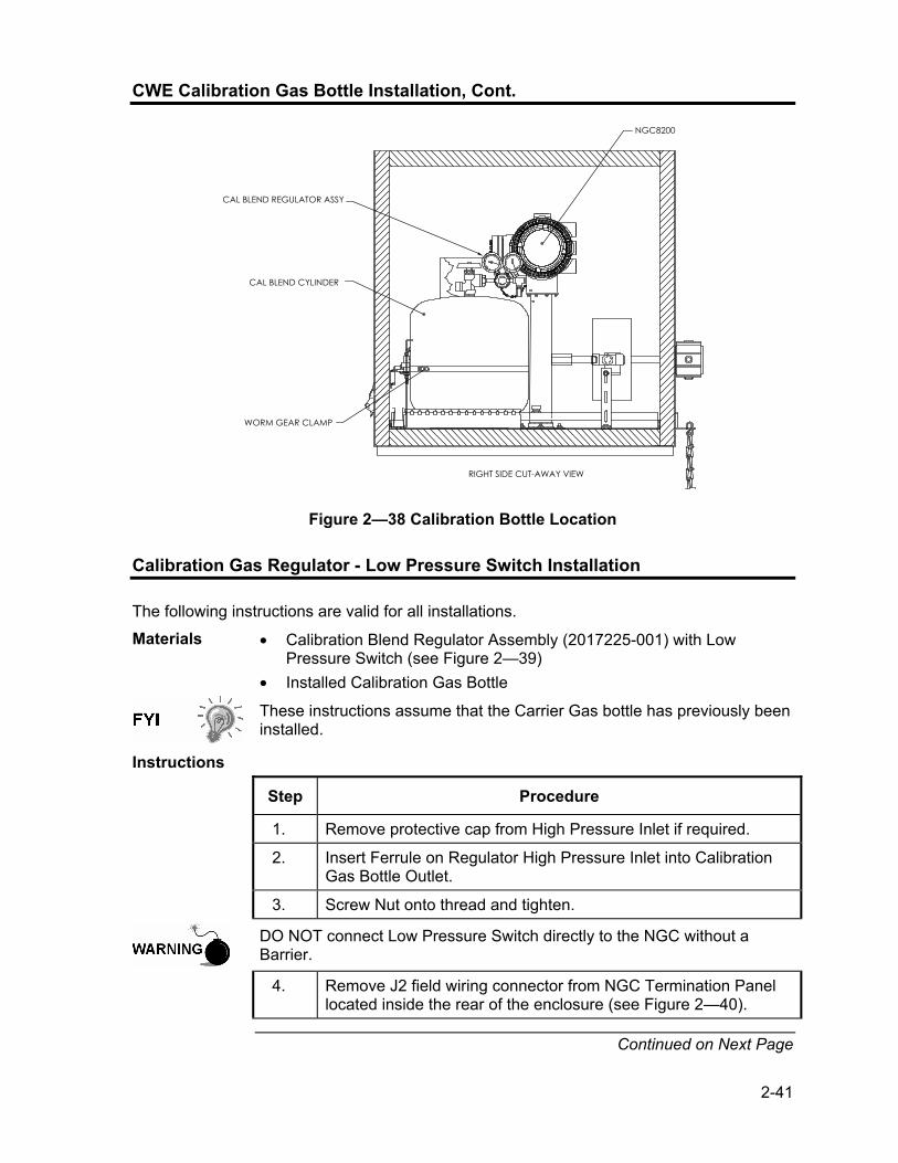
2-41
CWE Calibration Gas Bottle Installation, Cont.
CAL BLEND REGULATOR ASSY
CAL BLEND CYLINDER
WORM GEAR CLAMP
NGC8200
RIGHT SIDE CUT-AWAY VIEW
Figure 2—38 Calibration Bottle Location
Calibration Gas Regulator - Low Pressure Switch Installation
The following instructions are valid for all installations.
Materials • Calibration Blend Regulator Assembly (2017225-001) with Low Pressure Switch (see Figure 2—39)
• Installed Calibration Gas Bottle
These instructions assume that the Carrier Gas bottle has previously been installed.
Instructions
Step Procedure
1. Remove protective cap from High Pressure Inlet if required.
2. Insert Ferrule on Regulator High Pressure Inlet into Calibration Gas Bottle Outlet.
3. Screw Nut onto thread and tighten.
DO NOT connect Low Pressure Switch directly to the NGC without a Barrier.
4. Remove J2 field wiring connector from NGC Termination Panel located inside the rear of the enclosure (see Figure 2—40).
Continued on Next Page

2-42
Calibration Gas Regulator - Low Pressure Switch Installation, Cont.
Figure 2—39 Calibration Gas Pressure Regulator with Relief Valve
J2(-)(+) (-)(+) (-)(+) (-)(+)
INPUTS OUTPUTS1 1 22
DIGITAL I/0
NGC TERMINATION BOARD
BARRIER REQUIRED FOR ALL INSTALLATIONS OTHER THAN NON-HAZARDOUS
ASSYREGULATOR
CALBLENDCYLINDER
Figure 2—40 Calibration Blend Low Pressure Switch Wiring Instruction
Continued on Next Page

2-43
Calibration Gas Regulator - Low Pressure Switch Installation, Cont.
Step Procedure, Cont.
5. Using a small flat blade screw driver, loosen DI2 Pins 3 and 4.
6. Insert the Red wire into the (+) terminal (Pin 3).
7. Retighten Pin 3.
8. Insert the Black wire into the (-) terminal (Pin 4).
9. Retighten Pin 4.
10. Replace the termination connector in J2 board connector.
Carrier Gas and Calibration Gas Connections
The following procedures describe the steps for connecting the external Carrier Gas and Calibration Gas lines from the respective regulators to the Feed-Through Assembly on the NGC. They are applicable for both a Meter Run and Cold Weather Enclosure installation.
Materials • Installed Carrier Gas Pressure Regulator • 1/16” SST Chromatography Grade Transport Tubing (Amount to be
determined by technician based on distance from Carrier Gas Bottle Regulator to Sample Input Filter).
• Installed Calibration Gas Pressure Regulator • 1/16” SST Chromatography Grade Transport Tubing (Amount to be
determined by technician based on distance from Calibration Gas Bottle Regulator to Sample Input Filter).
• 4 ea. 1/16” Ferrule and Nut • 2 ea. ¼” NPT to 1/16” Reducer or other size as determined from
Carrier/Calibration Gas Regulator.
These instructions assume that the regulators and gas bottles have previously been installed.
Instructions
Step Procedure
1. Locate Carrier Gas Input Port (CAR) on NGC Feed-Through Assembly (see Figure 2—41).
2. Locate ¼” Low Pressure Output fitting on installed Pressure Regulator.
3. Measure and cut 1/16” SST Tubing to required length.
4. Make necessary bends in tubing to ease installation of the tubing into NGC and Pressure Regulator.
Continued on Next Page

2-44
Carrier Gas and Calibration Gas Connections, Cont.
Figure 2—41 Carrier and Calibration Gas Connections
Step Procedure, Cont.
Tube, Ferrule and Nut should always enter connection at a right angle.
5. Install reducer into Carrier Gas Regulator.
6. Insert tube with ferrule into reducer/Pressure Regulator output fitting. Move Nut down onto ferrule, screw onto fitting and tighten.
7. Carrier Gas Pressure should be set at 90 PSIG.
8. Locate Carrier Gas input (CAR) on NGC Feed-Through Assembly and remove sealing Screw.
Leave sealing screw in any unused ports. If unused stream ports are not sealed, moisture can enter the manifold which can damage the instrument and void warranty.
9. Purge air from the transport tubing by opening the shut-off valve located on the Regulator.
Be sure to follow requirements of national and local codes when performing this purge.
10. Insert tube with ferrule into Carrier Gas Input Port (CAR) on Feed-Through Assembly. Move Valco Nut down onto ferrule, screw into port and tighten.
Continued on Next Page

2-45
Carrier Gas and Calibration Gas Connections, Cont.
Step Procedure, Cont.
11. Determine input port for Calibration Gas (typically S4) on NGC Feed-Through Assembly (see Figure 2—41) and remove sealing screw.
12. Locate ¼” Low Pressure Output fitting on installed Pressure Regulator on Calibration Gas Bottle.
13. Measure and cut 1/16” SST Tubing to required length.
14. Make necessary bends in tubing to ease installation of the ferrule and tubing into NGC and Pressure Regulator.
Tube, Ferrule and Nut should always enter connection at a right angle.
15. Install reducer into Calibration Gas Regulator if required.
16. Insert tube with ferrule into reducer/Pressure Regulator output fitting. Move Nut down onto ferrule, screw onto fitting and tighten.
17. Calibration Gas Pressure should be set at 15 PSIG.
18. Purge air from the transport tubing by opening the shut-off valve located on the Regulator.
Be sure to follow requirements of national and local codes when performing this purge.
19. Insert tube with ferrule into Calibration Gas Input Port (S4) on Feed-Through Assembly. Move Valco Nut down onto ferrule, screw into port and tighten.
Leak test ALL gas connections when completed.
Vent Line Connections
The following procedure provides general steps for connecting the external Vent Lines from the respective output ports on the Feed-Through Assembly. When the NGC is installed in a Cold Weather Enclosure, Sample Vent line MUST vent outside of the CWE. Other installations may only require short lines. Please follow requirements of national and local codes during this installation.
Materials • 4 ea. 1/16” Ferrule and Nut • 4 ea. 1/16” SST Vent Tubing (supplied with NGC) or • 4 ea. 1/16” SST Tubing (Amount to be determined by technician
based on distance from NGC to external vent location).
Continued on Next Page

2-46
Vent Line Connections, Cont.
Instructions
Step Procedure
1. Locate GPV (Gauge Port Vent), SV (Sample Vent), CV1 (Column Vent 1) and CV2 (Column Vent 2) ports on NGC Feed-Through Assembly (see Figure 2—42). Remove sealing screws for vent ports.
2.
3. Using supplied Vent Tubing (if sufficient length) and Ferrule, place Nut and Ferrule onto short end of bent tubing. Insert tubing, and ferrule into one of the vent ports, with open end of tubing pointing down. Move Valco Nut down onto ferrule, screw into port and tighten. If Vent Tubing is not of sufficient length, measure and cut new tubing (not supplied by Totalflow). Make necessary bends to install tubing. Place Nut and Ferrule onto corresponding end of tubing. Insert tubing, and ferrule into one of the vent ports being careful to keep tubing horizontal, with open end of tubing pointing down. Move Valco Nut down onto ferrule, screw into port and tighten.
4. Repeat Step 2 for ALL other vents as listed in Step 1.
All 4 Vents MUST be open to atmospheric pressure without back pressure. Position Vent tubing in a downward direction so that moisture does not accumulate in the tubing.
Figure 2—42 Vent Line Connections on Feed-Through Assembly

2-47
CWE Optional Catalytic Heater Installation
The following procedures describe the steps for installing a Catalytic Heater for the Cold Weather Enclosure.
Verify the heater and fittings are approved for the classification rating of the area of installation.
Materials • Catalytic Heater (installed at factory) • Thermostat Assembly with Temperature Probe • Regulator Assembly W/ Shut-off • T Assembly • Tubing • Temperature Probe Mounting Clip • Teflon Tape • ¼” male pipe connection from External gas source to Catalytic Heater.
Materials for gas source is not provided by Totalflow. Quantities and materials to be determined by the technician based on installation and local codes.
• DC Power source wiring. Materials for external Power source for Electrical Preheat wiring are not provided by Totalflow. Quantities and materials to be determined by the technician based on installation and local codes.
Instructions
Step Procedure
1. Locate the installed Catalytic Heater on the rear of the Cold Weather Enclosure (see Figure 2—43).
2. Remove protective end cap from Catalytic Heater input fitting if required.
3. Apply Teflon tape to threads on male end of T Assembly (see Figure 2—44).
4. Screw threaded end of T Assembly into ¼” female fitting located on the factory installed Catalytic Heater, by turning entire Assembly clockwise until tight (see Figure 2—45).
5. Remove Ferrules and Nut from male connector on bottom of T Assembly.
6. From inside the CWE, insert short bent end of 3/8” Tubing out through hole located below Catalytic Heater, continue feeding tubing out until in position to insert into bottom of T Assembly.
Continued on Next Page

2-48
CWE Optional Catalytic Heater Installation, Cont.
Figure 2—43 Catalytic Heater Option in Cold Weather Enclosure
TEMPERATURE PROBE
3/8" TUBBING
MALE, 1/4 NPT
MALE CONNECTOR,3/8 x 1/4 NPT W/ FERRULES AND NUT
1/4 NPT PLUG
REGULATOR
MALE, 3/8 x 1/4 NPT
SERVICE COCK
THERMOSTAT
T ASSEMBLY TUBING THERMOSTAT ASSEMBLY REGULATOR ASSEMBLY
REGULATOR
Figure 2—44 Catalytic Heater Assembly
Figure 2—45 Thermostat Assembly Installed
Continued on Next Page

2-49
CWE Optional Catalytic Heater Installation, Cont.
Step Procedure, Cont.
7. Place Nut, Front Ferrule and Back Ferrule onto outside end of tubing and position so that the Ferrules and Nut screw onto the bottom of T Assembly. Screw Nut until tight.
8. Remove Ferrules and Nut from the Thermostat end of the Thermostat Assembly.
9. From inside CWE, insert tube end of Thermostat Assembly through exterior wall on the side of the CWE (see Figure 2—45).
10. Place Nut, Front Ferrule and Back Ferrule onto end of 3/8” bent tubing (from T Assembly beneath Catalytic Heater) inside of the CWE. Position Thermostat Assembly so that the Nut and Ferrules screw onto the Thermostat Assembly.
11. Remove Ferrules and Nut from end of the Regulator Assembly closest to Service Cock.
12. Place Nut, Front Ferrule and Back Ferrule onto end of Thermostat Assembly protruding from CWE.
13. Hold the Regulator Assembly with the curved tubing on top, above the protruding tubing. Insert tubing into Regulator Assembly, slide Ferrules and Nut into place and tighten (see Figure 2—46).
14. Gently uncoil Temperature Probe capillary tubing from Thermostat and insert through hole located below the Thermostatic Gas Valve, being careful to not crimp or make sharp bends in capillary tubing (see Figure 2—47).
15. Remove Mounting screw and washers from right rear NGC Mounting Bracket (see Figure 2—47).
16. Insert screw with washers still in place through hole located on the mounting clip and re-insert through mounting bracket into channel Nut (see Figure 2—47).
17. Position probe underneath the Mounting clip. Tighten screw into channel Nut to hold probe in place.
Technician responsible for installing gas supply must be qualified for the type and area of installation according to National and Local codes.
Continued on Next Page

2-50
CWE Optional Catalytic Heater Installation, Cont.
Figure 2—46 Regulator Assembly Installed
Figure 2—47 Temperature Probe Installation
Step Procedure, Cont.
18. Using Regulator manufacturer’s instructions supplied with Regulator, make external gas connections.
Installation must be performed by person(s) qualified for the type and area of installation according to National and Local codes.
19. Using the wiring instructions shown in Figure 2—48 and Manufacturer’s Instructions enclosed with Heater, make external connections.
Continued on Next Page

2-51
CWE Optional Catalytic Heater Installation, Cont.
12 VDC POWER SOURCE
POSITIVE
NEGATIVE
ELECTRICAL PREHEAT CONDUIT BOX
Figure 2—48 Electrical Pre-heater Wiring Instructions
CWE Optional Electric Heater Installation
The following procedures describe the steps for wiring an Electric Heater for the Cold Weather Enclosure.
Verify the heater and fittings are approved for the classification rating of the area of installation.
Materials • Electric Heater Option (Factory Installed, see Figure 2—49) • AC Power source wiring. Materials for external Power source for
Electric Heater wiring not provided by Totalflow.
Quantities and materials to be determined by the technician based on installation and local codes. Installation must be performed by person(s) qualified for the type and area of installation according to National and Local codes.
Instructions
Step Procedure
1. Using the wiring instructions shown in Figure 2—50 and Manufacturer’s Instructions enclosed with Heater, make external connections.
Continued on Next Page
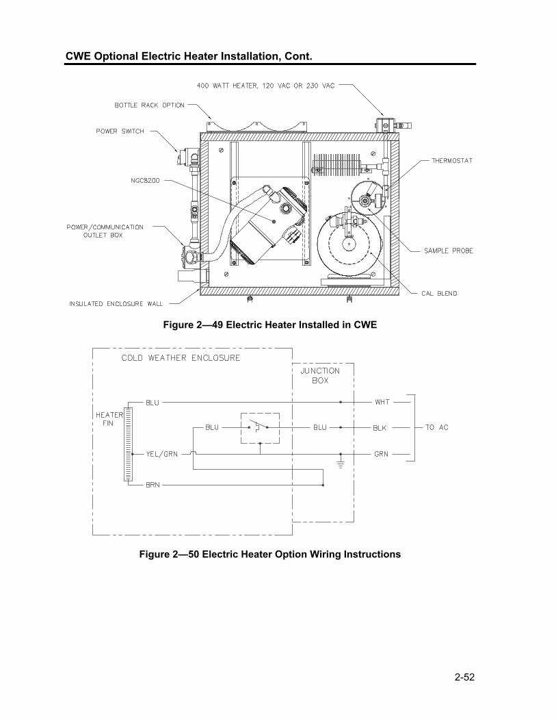
2-52
CWE Optional Electric Heater Installation, Cont.
C
Figure 2—49 Electric Heater Installed in CWE
Figure 2—50 Electric Heater Option Wiring Instructions

2-53
Optional Equipment Unit Installation
If optional OEU Enclosure is used, it may be configured to include other options, including, but not limited to a battery pack to provide reserve power to the NGC, communication equipment, solar power charger and additional I/O. Two enclosures are commonly used for the NGC installations. The 6470 OEU Enclosure and the 6770 OEU enclosure. The unit may be mounted on a 2” pipe, or mounted on a flat surface, such as a wall. Instructions for installation of mounting pipe may be found previously in this Chapter. If configured, the battery and solar panel are packed and shipped separately from the OEU. Before you begin, review the procedure and the materials required for installation, inspect all power cables where they terminate and connector for breakage.
The OEU may be approved for Classified Hazardous locations or potentially explosive atmospheres. Verify rating listed on the unit tag and install per the referenced Control Drawing. Be sure to follow requirement of National and Local codes when installing the OEU.
6470 OEU The 6470 can accommodate the following equipment: • Power Supply Kit for 6470 • 120VAC/12VDC power supply (2018554-001) • 240VAC/12VDC power supply (2018554-002) • 24VDC/12VDC DC to DC converter (2018554-003) The 6470 installation will be for AC and 24VDC sites. There is no battery backed option in this installation.
6770 OEU The 6770 OEU can accommodate the following: • Power Supply Kit
120VAC/12VDC power supply (2017493-001) 240VAC/12VDC power supply (2017493-002) 24VDC/12VDC DC to DC converter 2015440-005) Solar Panel Charger
• XFC/XRC Electronic Board XFC/XRC onboard battery charger will be used
• Battery Options 1 each 26/30AH battery
• Communications shelf for radio/modem The 6770 OEU supports battery backed operation for the NGC. The XFC/XRC electronic board provides a battery charger/regulator for the system.
Location Mount the enclosure on a nearby wall, panel or pole. Make sure that approved conduit can be installed between the power supply’s enclosure and the NGC. Avoid obstructions.
Continued on Next Page

2-54
Optional Equipment Unit Installation, Cont.
Pipe Mount Enclosure mounting brackets and fastening hardware are supplied with unit. Customer must provide 2” pipe of suitable length (see Figure 2—51). If a charging source, such as a solar panel is desired, this procedure may be adapted to mount the solar panel on the upper portion of the pipe.
Pipe Mount Instructions
Instructions assume mounting pipe has been previously installed. If not, refer to installation sections previously in this Chapter for either Free Standing Pipe Installation or Pipe Saddle Installation.
Step Procedure
2. When unit is received, unpack and inspect all components for evidence of damage. Report damage to shipping carrier and to Totalflow’s Service Department.
3. Using instructions supplied with mounting kit, attach bracket to back of enclosure unit.
4. Position unit on 2” mounting pipe (Part No. 2000089) and secure in place with two U-bolts, split washers, flat washers and two bolts (see Figure 2—51 and Figure 2—52).
Figure 2—51 6470 OEU Pipe Mounting Installation
Continued on Next Page

2-55
Optional Equipment Unit Installation, Cont.
(2.38 O.D.)2.00 PIPE
Figure 2—52 6770 OEU Pipe Mounting Installation
Wall Mount Before you begin, review the procedure and the materials required for installation. Typical installation should be similar to Figure 2—53 and Figure 2—54. Enclosure mounting brackets and fastening hardware are supplied with unit.
MOUNTING BRACKET
Figure 2—53 6470 OEU Wall Mounted Installation
Continued on Next Page

2-56
Optional Equipment Unit Installation, Cont
MOUNTING BRACKET
Figure 2—54 6770 OEU Wall Mounted Installation
Wall Mount Instructions
Step Procedure
1. When unit is received, unpack and inspect all components for evidence of damage. Report damage to shipping carrier and to Totalflow’s Service Department.
2. Using instructions supplied with mounting kit, attach bracket to back of enclosure unit.
3. Prepare wall surface for mounting, and mount the enclosure to wall.

2-57
Optional AC/DC Explosion Proof Power Supply Installation
Totalflow offers AC/DC power supplies housed in an Explosion Proof/Flame Proof enclosure that provides 12VDC to the NGC (see Figure 2—55 and Figure 2—56): • 115VAC to 12VDC • 230VAC to 12VDC
The AC/DC Power Supply may be approved for Classified Hazardous locations or potentially explosive atmospheres. Verify rating listed on the unit tag and install per the referenced Control Drawing. Be sure to follow requirement of National and Local codes when installing the Power Supply.
Customer Supplied Materials
• Plastic cable ties • AC wiring. Please refer to the Cable Recommendation Charts in
Chapter 1 (see Table 1-3 and Table 1-4). • Explosion Proof conduit with fittings and poured seals or approved
Explosion Proof/Flame Proof Flexible cable with fittings according to requirements of National and Local Codes.
AC POWER SUPPLY
4.62(1.38)
1.40
9.25
4.75
(10.50)
(12.00)
0.000(6.00)
0.000
(5.50)
(12.12)
#10−24 GROUND LUG
LOCKING SCREW
Figure 2—55 Explosion Proof AC Power Supply Top/Front Dimensions
Continued on Next Page
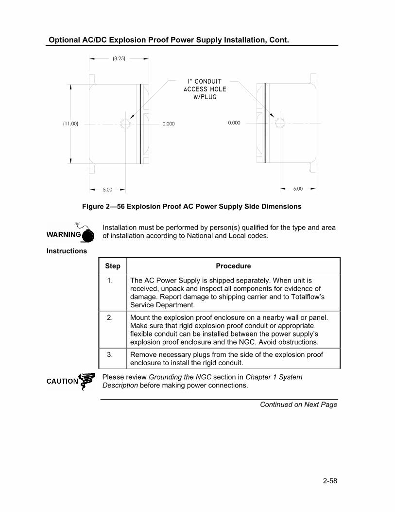
2-58
Optional AC/DC Explosion Proof Power Supply Installation, Cont.
5.00
0.000(11.00)
(8.25)
1" CONDUITaCCESS HOLE
w/PLUG
0.000
5.00
Figure 2—56 Explosion Proof AC Power Supply Side Dimensions
Installation must be performed by person(s) qualified for the type and area of installation according to National and Local codes.
Instructions
Step Procedure
1. The AC Power Supply is shipped separately. When unit is received, unpack and inspect all components for evidence of damage. Report damage to shipping carrier and to Totalflow’s Service Department.
2. Mount the explosion proof enclosure on a nearby wall or panel. Make sure that rigid explosion proof conduit or appropriate flexible conduit can be installed between the power supply’s explosion proof enclosure and the NGC. Avoid obstructions.
3. Remove necessary plugs from the side of the explosion proof enclosure to install the rigid conduit.
Please review Grounding the NGC section in Chapter 1 System Description before making power connections.
Continued on Next Page

2-59
Optional AC/DC Explosion Proof Power Supply Installation, Cont.
Step Procedure, Cont.
4. Pipe the conduit and associated AC wiring from external power source into the AC power supply enclosure.
5. Using wiring instructions in Figure 2—57, make field connections from 115VAC hot and neutral or the two hot wires for 230VAC to TB1 terminal 5A and terminal 6A on the Power Supply.
6. Pipe the conduit and associated DC wiring from the NGC into the power supply enclosure. See Table 1-3 in Chapter 1 for wire sizes.
7. Remove J1 Connector from NGC Termination Panel. Using wiring instructions in Figure 2—57, make field connections from the Power Supply wire from F1 Terminal B to J1 Connector (+) Pin and connect the Ground wire TB1 Terminal 1A to J1 Connector (-) Pin. DO NOT re-insert J1 Connector to Termination Board.
8. Go to DC Power Installation later in this Chapter. Explosion Proof Power
Supply Enclosure
Power Supply (Rotated for clarity)
ON OFF
115V/230V AC IN CABLE NOT USEDNGC8200 TERMINATION PANEL
SERIAL PORT 1 SERIAL PORT 2
1 2 1 2(+) (-) (+) (-) (+) (-) (+) (-)
INPUTS OUTPUTS
(+) (-)
J10J8
DIGITAL I/O POWER
S2
RESETS1
J7
J3
J2 J1
J5
J6
(-)
(+)
TERM TERMJ11J9
XMFR
(-)OUT
(-)OUT(-)S(+)S
(+)OUT(+)OUT
ACSWITCH
DCFUSE
WARNINGDO NOT USE
SWITCHUNLESS AREA IS
KNOWN TO BENON-HAZARDOUS
AC+
AC-
SHLD GND
(+)
(-)1A2A3A4A
1B2B3B
4B5B6B
5A
6ATB1F1A B
Figure 2—57 Explosion Proof AC Power Supply Wiring Instructions

2-60
Optional AC/12VDC Power Supply Installation
The 12VDC NGC is designed for a DC power source that must provide a minimum of 11.5VDC to a maximum of 16VDC at 4 amps minimum. Totalflow provides AC/DC Power Supplies that meet the requirements for converting 120VAC and 240VAC to 12VDC.
Available Converter Kits for the NGC8200 are:
• 6470 OEU (see Figure 2—58) 120VAC/12VDC power supply (2018554-001) 240VAC/12VDC power supply (2018554-002)
• 6770 OEU (see Figure 2—59) 120VAC/12VDC power supply (2017493-001) 240VAC/12VDC power supply (2017493-002)
Wiring Instructions for these kits follow.
DOOR
COMMUNICATIONSHELF
DC AC
ON
4
(-)S
(-)O
UT
(-)O
UT
(+)O
UT
(+)S
(+)O
UT
NON-HAZARDOUSKNOWN TO BE
UNLESS AREA IS
VOLTS
15 3
OFF
SW
ITCH
FUSE
2
Figure 2—58 6470 OEU Unit with Power Supply
Continued on Next Page

2-61
Optional AC/12VDC Power Supply Installation, Cont.
XMFR
(-)OUT
(-)OUT
(-)S
(+)S
(+)OUT
(+)OUT
KEEPER PLATE
COMMUNICATIONSHELF
DOOR
25
13
4
Figure 2—59 6770 OEU Unit with Power Supply
The AC/DC Power Supply may be approved for Classified Hazardous locations or potentially explosive atmospheres. Verify rating listed on the unit tag and install per the referenced Control Drawing. Be sure to follow requirement of National and Local codes when installing the Power Supply.
Installation must be performed by person(s) qualified for the type and area of installation according to National and Local codes.
Instructions
Step Procedure
1. If configured, the Optional Equipment Unit (OEU) should contain an installed AC Power Supply. OEU should be installed using instructions previously in this Chapter.
2. Remove necessary plugs from the side of the enclosure to install the rigid conduit.
Continued on Next Page

2-62
Optional AC/12VDC Power Supply Installation, Cont.
Instructions
Step Procedure, Cont.
3. Pipe the conduit and associated AC wiring into the OEU enclosure.
Please review Grounding the NGC section in Chapter 1 System Description before making power connections.
4. Using wiring instructions in Figure 2—60, make field connections from 115VAC hot and neutral or the two hot wires for 230VAC to TB1 terminal 5A and terminal 6A on the Power Supply.
5. Pipe the conduit and associated DC wiring from the NGC into the power supply enclosure. See Table 1-3 in Chapter 1 for wire sizes.
6. Remove J1 Connector from NGC Termination Panel. Using wiring instructions in Figure 2—57, make field connections from the Power Supply wire from F1 Terminal B to J1 Connector (+) Pin and connect the Ground wire TB1 Terminal 1A to J1 Connector (-) Pin. DO NOT re-insert J1 Connector to Termination Board.
7. Go to DC Power Installation later in this Chapter.
6470 Enclosure
POWER SUPPLY (ROTATED FOR CLARITY)
XMFR
(-)OUT
(-)OUT(-)S(+)S
(+)OUT(+)OUT
ACSWITCH
DCFUSE
ON OFF
WARNINGDO NOT USE
SWITCHUNLESS AREA IS
KNOWN TO BENON-HAZARDOUS
115/230V AC IN
AC+
AC-
BATTERY CABLE NOT USED IN 6470 OEU
SHLD GND
NGC8200 TERMINATION PANEL
(+)
(-)
SERIAL PORT 1 SERIAL PORT 2
1 2 1 2(+) (-) (+) (-) (+) (-) (+) (-)
INPUTS OUTPUTS
(+) (-)
J10J8
DIGITAL I/O POWER
S2
RESET
S1
J7
J3
J2 J1
J5
J6
(-)
(+)
TERM TERMJ11J9
1A2A3A4A
1B2B3B
4B5B6B
5A
6ATB1
F1A B
Figure 2—60 AC/DC Converter Wiring Instructions

2-63
Optional 24 VDC/12 VDC Power Converter
The optional 24 VDC to 12 VDC Power Converter may be used when available power supply is 24 VDC and NGC configuration is 12 VDC. Totalflow provides a power converter that meet these requirements. Wiring instructions for the power supply follows (see Figure 2—62). Available Chargers for the NGC8200 are housed in one of two OEU enclosures and are:
• 6470 OEU 24VDC/12VDC DC to DC converter (2018554-003)
• 6770 OEU 24VDC/12VDC DC to DC converter (2018200-001).
The DC/DC Power Converter may be approved for Classified Hazardous locations or potentially explosive atmospheres. Verify rating listed on the unit tag and install per the referenced Control Drawing. Be sure to follow requirement of National and Local codes when installing the Power Converter.
Instructions
Step Procedure
1. If configured, the Optional Equipment Unit (OEU) should contain an installed Converter. OEU should be installed using instructions previously in this Chapter.
2. Remove necessary plugs from the side of the enclosure to install the rigid conduit.
3. Pipe the conduit and associated DC wiring into the OEU enclosure.
Please review Grounding the NGC section in Chapter 1 System Description before making power connections.
4. Using wiring instructions in Figure 2—61, make field connections from 24VDC(+) and (-) source to TB1 terminal 11A (+) and terminal 12A (-) on the Power Supply.
5. Pipe the conduit and associated DC wiring from the NGC into the power supply enclosure. See Table 1-3 in Chapter 1 for wire sizes.
6. Remove J1 Connector from NGC Termination Panel. Using wiring instructions in Figure 2—61, make field connections from the Power Supply wire from TB1 Terminal 7A to J1 Connector (+) Pin and connect the Ground wire from TB1 Terminal 8A to J1 Connector (-) Pin. DO NOT re-insert J1 Connector to Termination Board.
7. Go to DC Power Installation later in this Chapter.
Continued on Next Page

2-64
Optional 24 VDC/12 VDC Power Converter, Cont.
S2
E
S EU
F U
FS E
S EU
F U
FS E
S EU
F U
FS
Figure 2—61 24VDC/12VDC Power Supply Converter
Optional OEU Battery Pack Installation
If optional 6770 OEU Enclosure is used, it may be configured to include a battery pack for reserve power. (see Figure 2—62) The battery is packed and shipped separately from the OEU. Before installation, inspect power cables located inside the OEU where they terminate on battery pack, and connector for breakage. Before you begin, review the procedure required for installation.
To extend the life of the Battery pack, fully charge the battery prior to installation. Systems using solar panels, may not fully charge the battery. Charging the battery fast will remove the oxide buildup and will improve the life of the battery.
DO NOT over charge the Battery Pack.
Continued on Next Page

2-65
Optional OEU Battery Pack Installation, Cont.
TB1F1
26 A
H BA
TTER
Y
BATTERY KEEPER
COMMUNICATION
XRC ELECTRONIC BOARD
SHELF
POWER SUPPLY
DOOR
PLATE
Figure 2—62 Optional 6770 OEU Enclosure
Instructions
Step Procedure
1. Insert battery(s) into the battery compartment (see Figure 2—62) with the long dimension of battery standing up with the terminals facing the door hinge.
2. Connect Battery Pack cables to battery connector mate(s) wired to either Charger Controller Assembly (see Figure 2—63) or J16 Battery Connector on the XFC/XRC Electronic Board acting as a Charger Regulator (see Figure 2—64).
3. Reinstall Battery Keeper Plate inside of enclosure if applicable.
DO NOT connect other end of cable until instructed to do so.
4. Go to DC Power Installation later in this Chapter.
Please review Grounding the NGC section in Chapter 1 System Description before making power connections.
Continued on Next Page
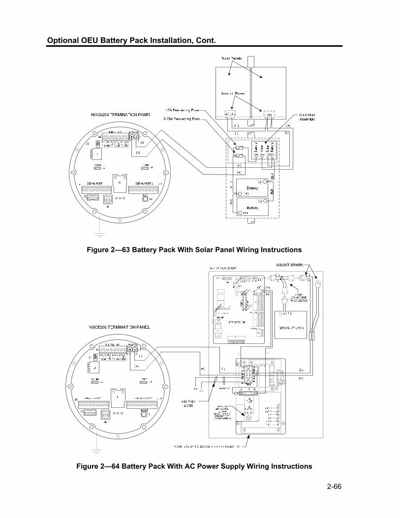
2-66
Optional OEU Battery Pack Installation, Cont.
Figure 2—63 Battery Pack With Solar Panel Wiring Instructions
Figure 2—64 Battery Pack With AC Power Supply Wiring Instructions

2-67
Optional 12V Solar Power Supply
The NGC is designed for connection to a DC power source and may be from the optional Totalflow Solar Power Supply Kit. Installation instructions for the Optional Solar Panel are included with the equipment. General instructions and wiring to the NGC are as follows. The Solar Panel is designed for outdoor mounting on a pipe installed on upper end of Controller/Battery enclosure.
If Solar Power System (1488010-501) is configured, Manufacturer’s installation instructions should supersede instructions in this User Manual.
Hardware • 1 ea. Controller Assembly/Battery Enclosure • 2 ea. 100 AH Batteries • 2 ea. 50 W Solar Panels • Mounting Hardware Check the manufacturer’s list of materials provided. Make certain that all required system components are present and in good condition.
This device is NOT approved for any Classified Hazardous Locations or potentially explosive atmospheres.
Instructions
Step Procedure
1. You should find a list of installation instructions included with the solar equipment.
2. Check solar panel using Digital Multimeter to verify polarity and output voltage. Voltage will vary depending on amount of sun, angle to sun, etc.
3. Follow Manufacturer’s installation Instructions.
Solar Panel installation location should ensure that panel receives full sun all day. When mounted, Solar Panel will face up from horizon at 50° angle.
The sun’s orientation in the sky varies from summer to winter. Keep this in mind when installing the solar panel to make sure there are no obstructions during the entire year.
4. For northern hemispheres, position Solar Panel facing South, for southern hemispheres, position Solar Panel facing North. For optimum charging, solar panel should not be in shadows for any portion of the day. Panel should be kept clean for maximum charging.
Continued on Next Page

2-68
Optional 12V Solar Power Supply, Cont.
Do not connect the solar panel power cable to the Controller Assembly located in the enclosure unless main Battery Pack has been connected.
Please review Grounding the NGC section in Chapter 1 System Description before making power connections.
Step Procedure, Cont.
5. Using wiring instructions in Figure 2—65, make field connections from Controller Assembly to Battery Pack.
6. Using wiring instructions in Figure 2—65, make field connections from Solar Panel to Controller Assembly.
7. Remove the J1 Power connector from the Termination Panel inside the rear of the NGC enclosure.
8. Using wiring instructions in Figure 2—65, make field connections from Controller Assembly to NGC J1 Power Connector. Red Wire from Controller Assembly should be connected to Pin 1 (+) and Black wire should be connected to Pin 2 (-).
9. DO NOT re-insert into corresponding connector into board. Power will be applied later in this Chapter.
Batte
ry
(+)
(-)
(+)(-) (+)
Solar Panels
Junction Boxes
(-)
(+)
(-)
(+)
(-)(-)(+)(+)
Battery
Sola
r
Sola
rBa
ttery
Battery
10A Fast-acting Fuse
6.25A Fast-acting Fuse
(-)
(+)
Controller Assembly
RE
D
BLK
BLK
RE
D
(+)
(-)
NGC8200 TERMINATION PANEL
SERIAL PORT 1 SERIAL PORT 2
1 2 1 2(+) (-) (+) (-) (+) (-) (+) (-)
INPUTS OUTPUTS
(+) (-)
J10J8
DIGITAL I/O POWER
S2
RESETS1
J7
J3
J2 J1
J5
J6
(-)
(+)
TERM TERMJ11J9
Figure 2—65 Solar Power Supply Wiring Instructions

2-69
DC Power Installation
These instructions assume that all external wiring has been completed to point where connections have been made to field termination connector, but the connector has not been plugged into the Termination Panel.
Instructions
Step Procedure
1. If installation includes the Optional Power Switch: • Apply power to switch, turn switch to “ON” position.
If installation includes the Optional Equipment Unit with the Optional Power Supply: • Apply power to Power Supply.
If installation includes a Solar Panel connected to a Battery: • Plug in Charger Regulator battery connector.
2. Test power using a Multi-Meter connected to J1 terminals of Phoenix Connector: 12 Volt System: voltage is between 11.5 and 16.0 volts (see Table 1-3). 24 Volt System: voltage is between 21.0 and 28.0 volts (see Table 1-4).Table 1-3 12V Battery Power Supply System Maximum Cable Lengths
3. If volts are within range, the power should be disconnected, Phoenix Connector inserted into Termination Panel J1 Connector and power re-applied. During Startup operations, unit will require: 12 Volt System: 11.5 volts minimum. 24 Volt System: 21.0 volts minimum.
4. If NGC8200 has optional VGA Screen, unit will show “Totalflow Boot Loader” followed by navigational screen when functional.
5. Unit will begin Start-up Diagnostics and oven stabilization. This completes the hardware installation. Proceed to the next chapter “Start-up “ to begin unit setup and operation.

2-70
Remote Communication Installation
As remote communication installation is specific to the communication transceiver, only basic information is supplied here. Additionally, wiring instructions should be shipped with the unit. Both Communication ports (Serial Port 1 and 2) can function as RS-232, RS-422 or RS-485. Table 2-1 shows Serial Port Pin Outs and Termination Settings.
PCCU32 To communicate remotely with the Host, the NGC defaults to Port 1 and the protocol defaults to Totalflow Remote. This protocol deals primarily with communications between the NGC and Host (typically WinCCU). Port 2 is defaulted as an NGC Interface and communicates via Modbus, functioning as a Modbus Slave.
All communication parameters are found on the Setup tabs for each instantiated communication application in PCCU32. Systems are shipped with default settings for communications but may need fine tuning. For additional information, please refer to the PPC32 Help Files.
Table 2-1 Port 1 and Port 2 Pin-Outs/Terminations
RS-232 RS-485 RS-422
PIN PORT 1 (J8) PORT 1 (J8) PORT 1 (J8)
1 Power Out Power Out Power Out 2 Ground Ground Ground 3 Switched Power Out Switched Power Out Switched Power Out 4 Operate Operate Operate 5 Not Used RRTS RTS 6 Request To Send Bus + Transmit Bus + 7 Transmit Data Bus - Transmit Bus - 8 Receive Data No Connection Receive Bus + 9 Clear To Send (CTS) No Connection Receive Bus - PIN PORT 2 (J10) PORT 2 (J10) PORT 2 (J10)
1 Power Out Power Out Power Out 2 Ground Ground Ground 3 Switched Power Out Switched Power Out Switched Power Out 4 Operate Operate Operate 5 Not Used RRTS RTS 6 Request To Send Bus + Transmit Bus + 7 Transmit Data Bus - Transmit Bus - 8 Receive Data No Connection Receive Bus + 9 Clear To Send (CTS) No Connection Receive Bus - TERMINATIONS PORT 1 (J9) PORT 2 (J11)
First or Intermediate Unit (RS-485) Pins 2–3 Pins 2–3 Last or Only Unit (RS-485) Pins 1–2 Pins 1–2 RS-232 Pins 2–3 Pins 2–3

3-1
Chapter 3 NGC Start-up
Overview
This Chapter generally describes the minimum requirements to Start-up a newly installed NGC system. Specific details to further customize the NGC are discussed in the PCCU32 Help files.
DO NOT open or remove covers, including the PCCU Local communications cover, unless the area is known to be Non-hazardous, including the internal volume of the enclosure.
Highlights This Chapter covers the following topics:
Topic See Page PCCU32 Installation and Setup 3-1 Ethernet Installation and Setup 3-3 Connecting to the NGC’s Local Port 3-7 NGC Diagnostics 3-9 NGC Start-up Wizard 3-9 Calibrating the NGC 3-14 Security System 3-16 Alarm Definitions 3-17
Before you begin you should complete the tasks outlined in the Chapter 2.0, Installation.
PCCU32 Installation and Setup
Totalflow’s® PCCU32 6.0 (or later) Software is required to communicate with the NGC8200. Previous versions of PCCU32 are not compatible with the NGC8200. PCCU32 Software running in a laptop Windows Desktop environment offers you the most capabilities for programming the NGC. The Windows environment features user friendly help files and easy to follow menus. Having help files readily accessible to the user is comparable to having a virtual teacher on location. Easy to follow menus and icons, step the user through many required choices. The Totalflow NGC8200 Hardware is designed using Windows Mobile technology CE operating system. Therefore communication between a Personal Computer and the NGC8200 may be accomplished using a USB cable. When this method of communication is desired, Windows ActiveSync is required and supplied with PCCU32.
Continued on Next Page

3-2
PCCU32 Installation and Setup, Cont.
Software Installation
Step Procedure
1. Insert PCCU32 disk into PC drive. If CD drive is set to Auto Play, the installation program should begin, otherwise, go to Start, Run and type in D:\Disk1\setup.exe, D being the CD Drive designation.
2. Follow screen prompts during installation. When asked if you want to install ActiveSync, your answer depends on whether the unit was shipped with a USB (default) or a round RS-232 military type connector as the Local Port connector. This is the connector on the outside of the unit with the round explosion proof cap. If USB, you will need to check the install ActiveSync box. If communicating via RS-232, simply click the Next button. If you communicate with a PDA, you already have ActiveSync installed, but this installation may contain a later version allowing you to upgrade. To verify your version, open ActiveSync, click Help and About Microsoft ActiveSync.
3. Another screen prompt will allow you to select the correct port for communication: USB Port for connecting via USB, Serial Port for connecting via RS-232. If you have previously installed the PCCU software and selected a port and you are re-installing or upgrading, select Keep Current Port.
4. The installation puts a PCCU_NGC folder on the Window’s desktop with shortcuts. The shortcuts will be correct, assuming the install directory was not changed. If the install directory was changed the shortcuts will have to be changed to the new directory path. If using a network, the NGC on the Network shortcut will require a network ID or IP address. For a standalone desktop shortcut, right-click on the shortcut, select Create Shortcut and drag it to the desktop.

3-3
Ethernet Installation and Setup
Installation of an NGC in a network environment may be implemented using the following instructions. Some decisions may require input from your network administrator. PCCU32 communication with the NGC over an Ethernet Connection (TCP/IP) requires the use of either a Hub, Switch or Router (see Figure 3—1). Ethernet (local) communication in a remote area may also be utilized. PCCU32 makes use of the Windows DHCP Utility. Dynamic Host Configuration Protocol (DHCP) can randomly assign a unique IP address within the defined Subnet Mask. This utility also allows user to define a more user friendly Network ID. This ID must be unique within the Subnet Mask. However, a new IP address may be automatically assigned to the NGC if the NGC’s power is cycled. For this reason, it may be preferable to disable the DHCP. Disabling the DHCP, requires that a unique IP Address be assigned, generally by the network administrator.
Figure 3—1 Ethernet Connections
Continued on Next Page

3-4
Ethernet Installation and Setup, Cont.
TCP/IP Network Connection
Materials Required: • Ethernet Straight through Cable (see Figure 3—2). • Hub, Switch or Router and associated wiring to NGC (see Figure 3—
1).
Step Procedure
1. Acquire TCP/IP Network Settings: • From the PC’s Start Menu, select Run. • Type the program name “CMD” in the Open window. • Press OK. • At command prompt, type ipconfig /all (space after
…ipconfig). • Record the PC and LAN settings displayed for later use.
2. Make local connection to NGC using either USB or RS-232 cable to do initial setup of parameters.
3. From the Analyzer Operation screen in PCCU, click on Show Tree View button in the upper left corner of screen.
4. Click on Communications to show the communication setup screen.
5. Select the Network tab.
If using a Windows network, you may wish to use the Network ID feature. Network ID’s are limited to 15 alphanumeric digits, with limited special characters. Please see Windows Help Files for more information on naming computers.
87654321 8
7654321Not Used
RX-
RX+TX-TX+
Not Used
Not UsedNot Used
Not UsedNot Used
Not UsedNot Used
87654321 Orange/White
87654321
OrangeGreen/White
BlueBlue/White
GreenBrown/White
Brown
Straight-Through Cable
Connector Clip
End View
RX-
RX+TX-TX+
8
1
Figure 3—2 Ethernet Cable-Typical
Continued on Next Page

3-5
Ethernet Installation and Setup, Cont.
Step Procedure, Cont.
6. Enable or Disable the Dynamic Host Configuration Protocol (DHCP). To disable DHCP and assigned IP address, set to No, continue to next Step, otherwise select Yes and skip to Step 6.
7. Enter IP address assigned by the Network Administrator and Subnet Mask if different (default is 255.255.255.0).
8. When all desired changes have been made, select Send.
9. Reset NGC by pressing the Reset button located on the Termination Panel housed in the rear of NGC enclosure.
10. Verify Ethernet communication: • Change to TCP/IP Network cable. • Enter Windows Start Menu, select Run, then type CMD to
open the Command window. 11. At prompt “>” type “ping” followed by a space, then either the
Network ID or IP Address, press enter. A successful communication will show multiple replies for the unit.
TCP/IP Local Connection
Material Required: • Ethernet Cross-over Cable (see Figure 3—3).
Step Procedure
1. Make local connection to NGC using either USB or RS-232 cable to do initial setup of parameters.
87654321 8
7654321Not Used
RX-
RX+TX-TX+
Not Used
Not UsedNot Used
Not UsedNot Used
Not UsedNot Used
TX+TX-RX+
RX-
87654321 Orange/White
87654321
OrangeGreen/White
BlueBlue/White
GreenBrown/White
Brown
Orange
GreenOrange/White
Green/White
Blue/WhiteBlue
Brown/WhiteBrown
Crossed-Over Cable
Connector Clip
End View
8
1
Figure 3—3 Ethernet Cable-Cross-Over
Continued on Next Page

3-6
Ethernet Installation and Setup, Cont.
Step Procedure, Cont.
2. From the Analyzer Operation screen in PCCU, click on Show Tree View button in the upper left corner of screen.
3. Click on Communications to show the communication setup screen.
4. Select the Network tab. Enable DHCP. Send Changes and record new IP address for later use.
5. Exit PCCU and disconnect local communication cable
6. Connect Ethernet Cross-over Cable between PC and NGC.
7. Open PCCU software. Click on Operate on the menu bar. Move down the drop-down list to Setup and move across to the new menu and select System Setup.
8. Under communications, set the PCCU Com Port to TCP and enter the IP Address previously noted in the Network ID or IP box. Close System Setup screen.
9. Verify TCP/IP communications by clicking the Entry Button on the main screen (upper most left button).
Should you receive a “Communication Link Failed” error message, investigate the following possible causes: • Verify a crossover Ethernet is being used and not a straight through
Ethernet cable. • If using a network hub or network, verify firewall is not blocking the
IP address. • If laptop is connected to a network, verify a Virtual Private Network
(VPN) is not being used to access a corporate network. The VPN may need to be disconnected before a local Ethernet connection is possible.

3-7
Connecting to the NGC’s Local Port
The laptop computer connects to the Local Port via USB or RS-232 using one of two cables (See Figure 3—4).
ActiveSync software is required to communicate when using USB. If ActiveSync was not installed during the PCCU32 installation, connecting the USB cable should trigger the ActiveSync installation to begin.
Communicate
Step Procedure
1. Connect the MMI cable to the designated port on your PC and to the Local Port located on the outside of the NGC. If unit is configured for the RS-232 MMI cable, connect to appropriate communication port on PC (default is COM1). If unit is configured for USB cable (PN.1801800-xxx), connect Host end of USB cable to any USB port on the PC.
2. Although we previously discussed shortcuts, lets do the traditional way of clicking on the Windows Start button, selecting Programs, PCCU_NGC (or correct program folder if changed during installation), then select PCCU32. This will display PCCU32’s initial screen.
USB Cable
P/N 1801800-xxx RS-232 Cable
P/N 2015240-xxx
Figure 3—4 MMI Communication Cables
Continued on Next Page

3-8
Connecting to the NGC’s Local Port, Cont.
Step Procedure, Cont.
3. Assuming the MMI cable is connected, click on the Connect Icon (left-most icon at the top of the screen). If this unit had been previously setup, the [Local Connect] screen would appear with some labeled buttons. However, since going on the assumption that we are setting up the unit for the first time, The NGC Startup Wizard will appear. If so, see NGC Startup on the next page.
If the Invalid Security Code screen should appear, enter four zeros (0000) for the new code and click OK. The NGC should have defaulted to 0000 on Start-up.
4. Again, if the unit has already been set up, the Local Connect screen displays two buttons, Entry Setup and Collect Historical Data. Clicking on the Entry Setup will take you to the Analyzer Operation screen which has links to other operations. Daily operations should be performed from this screen. Historical data collection can also be performed from here by clicking on the Collect icon at the top of the screen.
If you get a communication error, click on the Setup Icon along the top of the screen and verify the PCCU Com. Port. If using USB, this should indicate USB; if not click on the down arrow and scroll down and select USB. If you are using serial communications with the round connector on the NGC end, select the communications port being used (COM1, etc.). When finished, Close the Setup screen and click the Connect icon again.

3-9
NGC Diagnostics
Previously in Chapter 2 Installation, the DC power circuit to the NGC was completed. Once power was applied to the unit, the NGC began Start-up procedure: • Unit Cold started, loading Start-up information into RAM memory • Start-up Diagnostics run. If diagnostics are not successful, unit will return a System Fault
and cease Start-up. Start-up Diagnostics consist of 4 areas of testing: • Carrier Pressure Regulator Test • Oven Temperature Test • Processor Control Test • Stream Test As noted above, Oven Temperature Test is one of the diagnostic tests run. To pass this test, the oven temperature must reach 60° C and somewhat stabilize, plus part of the Processor Control Test is testing the amount of effort the oven controller takes to keep the oven at its set point of 60° C. Based on ambient temperatures, this could take up to an hour. During this time, the user can be entering information via the Startup Wizard. During the initial start-up, all streams are disabled. During the Stream Test, streams with input pressure will be re-enabled, tested and either passed or failed. Streams with no initial input pressure will fail and left disabled. Streams can always be re-enabled later if they will be used. During the diagnostics or upon completion, you may view the status of the diagnostic tests by clicking on the Diagnostics button of the Analyzer Operation screen. Part of the Startup Diagnostic takes you to the Diagnostic screen. When unit completes the Startup Diagnostics and has passed the appropriate tests, with the exception of streams with no pressure, the unit will go into Hold mode. Totalflow recommends that the unit be allowed to run at least 8 hours to completely stabilize and then a calibration performed. This is also spelled out in the Startup Wizard.
NGC Start-up Wizard
After starting PCCU32 and clicking the Connect Icon as discussed earlier, the NGC Startup Wizard begins automatically. This will only happen the first time you connect to the unit or each time you reconnect to the unit and have not completed the Startup Wizard. The wizard will walk you through the process of entering all the necessary information to get your NGC up and running. Each screen has an associated Help screen that automatically displays when you move from screen to screen.
Step through all the screens in the Start-up Wizard filling in the required information. The unit may be concurrently running the Startup Diagnostics as you are entering data into the Wizard. One of the steps in the Wizard is displaying the Diagnostics screen to see the results. If the Diagnostics are still in progress, the Wizard will not allow you to continue until they finish.
The following procedure is only an outline and specific steps are discussed in the Wizard Help File.
Continued on Next Page

3-10
NGC Start-up Wizard, Cont.
Station Setup
Step Procedure
1. Enter Station ID (10 alphanumeric digits) and Location (24 alphanumeric digits) (see Table 3-1). Station ID should be a unique identifier from other NGC’s you may communicate with.
2. Verify Date/Time, if incorrect Set Device with the PCCU Date/Time to Yes.
Additional items in the Station Setup screen are not required for Start-up. For more information regarding the setup of these items, see the topic on the Start-up Help displayed with each screen.
3. When all desired changes have been made, select Send and then Next to move to the next screen.
Table 3-1 Station Setup Screen Information
Description Value
Station ID Assign unique Identifier (10 alphanumeric digits)
Location Enter information regarding meter location (24 alphanumeric digits).
Date/Time Shows current unit Date/Time
Set Device with PCCU Date/Time Resets device Date and time to match PC
Stream Setup
Step Procedure, Cont.
4. Enter Stream ID and Location, Contract Settings and Calculation Settings (see Table 3-2).
5. When all desired changes have been made, select Send and then Next to move to the next screen.
6. Complete steps 4 and 5 for each Sample Stream.
During Stream Setup, please note that each time you select Next, you should see the Stream ID, located on the first line of each screen, change value. You must move through all 4 streams even if the unit is a single stream unit.
Continued on Next Page

3-11
NGC Start-up Wizard, Cont.
Table 3-2 Stream Setup Screens
Setup Tab Available Values
Stream ID Assign unique Identifier (10 alphanumeric digits)
Location Enter information regarding meter location (24 alphanumeric digits).
Calibration Stream Stream #4 (default) Stream # 1, Stream #2, Stream #3 or Stream (Any)
Contract Settings Value Available Units Contract Pressure 14.73 PSIA (default) KPa, InH20, Mbar, InHg, PSIA, Bar, mmHg, PSFa,MPa, Pa
or kgcm2
Contract Temperature 60.00 F(default) C, F, R or K
Relative Humidity 100.00 %(default) Percent
Contract Hour 0 (default) Hour (0-23)
Calculation Settings Value Current Calculation File GPA-2172-1996(AGA8), ISO-6976-1995, etc.1
Sum IC5 & NeoC5 No (default), Yes
C6+ Index Split Mode2 Default-User Defined with C6+ Reported, 47.466% C6 35.340% C7 17.194% C8, 50% C6 50% C7 0% C8, 50% C6 25% C7 25% C8, 57.143% C6 28.572% C7 14.285% C8, User Defined C6+ Not Reported.
C6, C7, C8, C9, C10` Used to enter split percentages if desired.
Calibration Setup
Step Procedure, Cont.
7. Verify that each Process Stream is setup to use the correct Calibration Stream (Stream 4 Default). To make changes to the Calibration Stream for each Process Stream, use the Back button to return to the Setup for the Stream and make changes.
8. Change Calibration Cycles Average and Purge Cycles if required. Default Calibration Cycles Average is 3 and Purge Cycles is 2.
9. Make changes to the concentrations in the % BLEND column insuring that the Total Mole % equals 100%.
Continued on Next Page
1 File selection automatically sets the remainder of items on this screen. See PCCU Help files for more information. 2 Note that making a selection in this field (other than User Defined) will override any values in the C6+ Split Percent area of the Stream Setup screen.

3-12
NGC Start-up Wizard, Cont.
Step Procedure, Cont.
Caution should be used when entering Component Blend percentages to carefully match the components labeled on the Calibration Bottle. Mistakes will cause incorrect values.
If the Total Mole % does not equal 100% exactly, add or subtract the remainder to or from Methane (C1) to force the total to 100%.
10. When finished and Total Mole % equals 100.00 %, select Next to move to the next screen.
11. When all desired changes have been made, select Send and then Next to move to the next screen.
Diagnostics
Step Procedure, Cont.
12. As discussed earlier, Diagnostics began when power was applied to the unit. You cannot proceed beyond the Diagnostics screen until diagnostics have passed. When completed, select Next to move to the next screen.
13. To change the run order of Process Streams, change values beside Sequence Numbers. In this same screen, streams may be disabled or enabled.
During the initial start-up, all streams will be disabled. During the Stream Test, streams with input pressure will be re-enabled, tested and either passed or failed. Streams with no initial input pressure will fail.
To enable or disable streams after completion of Diagnostics, select Stream Sequence from the Analyzer Operation screen. Totalflow recommends that the Diagnostic Stream Test be preformed on streams enabled after initial Diagnostics. Select the Help button for additional information.
14. When all desired changes have been made, select Send and then Next to move to the next screen.
Update Configuration
Step Procedure, Cont.
15. Totalflow recommends that you save the unit configuration file following setup. Change the Value beside Save Configuration Data to Now to save configuration.
Continued on Next Page
3-13
NGC Start-up Wizard, Cont.
Step Procedure, Cont.
16. Select Send and then Next to move to the next screen.
Analyze Calibration Stream
Step Procedure, Cont.
17. Prior to running Sample Streams, the NGC should run the Calibration Stream (default Stream 4). Select Stream 4 on the left side of the screen. The button beside Stream 4 should illuminate, the Cycle Clock will begin and you should see animated gas running on the Calibration Stream.
18. Allow stream to process for 2 or 3 cycles (approximately 10 to 15 Minutes). During final cycle, change Next Mode to Hold. When unit completes the current cycle, it will enter Hold Mode.
19. Select Next to verify Analysis Results.
20. Compare Normalized % for each Component to Component and percent listed on the Calibration Blend Bottle. Component percentages should be relatively similar.
There won’t be any comparisons for C6+ individual components. There may be values in the Normalized column for Hexane thru Decane, but this is based on the C6+ configuration entered in Stream Setup. For comparison purposes, use the Components called Heavies.
21. Select Next to verify Heavy Components on Chrom-1.
22. Verify that the appropriate components are visible and labeled. For the standard C6+ application, you should see C6+, C3, iC4, nC4, neoC5, iC5 & nC5. The 2nd peak from left that looks like two peaks is a composite peak of C2- and is not used in calculations.
23. Select Next to verify Light Components on Chrom-2.
24. Verify that the appropriate components are visible and labeled. You should see N2, C1, CO2, & C2. The 1st peak on the left is a composite peak of C3+ and is not used in calculations.
25. Select Next to begin Process Stream Analysis. Select Run on the left side of the screen to begin the first process stream in the Sequence. The buttons beside Run should turn blue, the Cycle Clock will begin and you should see animated gas running on the Process Stream.
Continued on Next Page

3-14
NGC Start-up Wizard, Cont.
Start-up Completion
Step Procedure, Cont.
26. Unit should continue to cycle through all enabled streams performing analysis and producing data.
27. Totalflow recommends that the unit be allowed to run at least 8 hours before calibration to allow unit to stabilize.
28. Select Close to complete the Start-up Wizard and return to PCCU’s Local Analyzer Operation screen. If completed satisfactorily, the Start-up Wizard should not re-appear when connecting to unit. However, should you like to review or make changes, you may re-enter the Wizard by selecting NGC Start-up Wizard from the Help drop-down menu.
Calibrating the NGC
The NGC is factory calibrated, and should not require that a calibration be performed immediately. It is recommended the unit operate for a period of 8 continuous hours before a field calibration. At that time, a field calibration should be performed. This will allow adjustments due to your location’s barometric pressure and other factors to be taken into consideration. A Calibration Cycle includes Purge Cycles and multiple Calibration Cycles for averaging. System defaults to Stream 4 (cal stream), 2 Purge Cycles and 3 Calibration Cycles. When calibration is complete a thorough examination of the results should follow.
Allow the NGC to run for a minimum of 8 hours before a field calibration is performed.
Instructions
Step Procedure
1. From the Analyzer Operation screen, select Cal.
2. When the current cycle completes, the unit should begin a calibration on the designated Cal Stream (Stream 4 default).
3. When calibration is complete, unit should move to the designated Next Mode. View results on the Analyzer Operation screen.
Continued on Next Page

3-15
Calibrating the NGC, Cont.
Step Procedure, Cont.
4. The calibration stream’s UnNormalized total should be ±.5% (between 99.5% and 100.5%).
If values exceed these parameters, proceed to the Troubleshooting Section of this manual.
5. Carefully examine the calibration stream’s Chrom-1 and Chrom-2 by clicking on the button. Look for unlabeled peaks and base line anomalies. Figure 3—5 and Figure 3—6 should be used as a guide.
If errors exist, proceed to the Troubleshooting Section of this manual.
6. Once unit is running smoothly, producing good chroms and all the peaks are labled and eluting correctly, perform a Save and Restore procedure to update tfCold.
Figure 3—5 Typical Chromatograph for Chrom-1 (Heavies)
Continued on Next Page

3-16
Calibrating the NGC, Cont.
Figure 3—6 Typical Chromatograph for Chrom-2 (Lights)
Security System
The NGC Board has a bi-level security system built in. For the purpose of this manual, we will refer to this as Hardware Security. When the NGC is accessed through PCCU32 or WINCCU Host software packages, either remotely or locally, there is a third level of security included. We will refer to this as the Software Security. The Security Switch located on the Termination Panel of the NGC, must be switched down for the Hardware Security system to be functional. The switch must be switched up to change the devices security code. Security Codes are checked via remote communication whether the switch is on or off.
Security Code When setup as designed, each user “logs on” to the system with a unique user name (up to 25 alphanumeric digits) and 4 digit alpha-numeric password before connecting to the unit.
Hardware Security
The Hardware Security System is designed to have two levels of user access; 1) reading data files, read only access, and 2) sending application and configurations, read/write access. By default, user access is restricted from modifying the Application Table or from downloading files to the device’s TFData and TFCold drives, but has all other user type privileges. These default privileges can be edited by the Administrator and consist of 4 digit alphanumeric pass codes, Level 1 and Level 2.
Continued on Next Page

3-17
Security System, Cont.
Software Security
The Software Security System is designed for the Password Administrator to set up the accounts and privileges for himself as well as all other Host Software users. These privileges include being able to instantiate applications and make changes to the functionality of the NGC. A second level of user access includes Application Editing and Downloading Files to a device. User access by default is restricted from modifying and downloading the Application Table or from downloading files to the device’s TFData and TFCold drives, but has all other user type privileges. These default privileges can be edited by the Administrator and consist of a User Name (up to 25 alphanumeric digits) and a Password (up to 25 alphanumeric digits).These are separate privileges, and may be given individually or totally. See the help files in the host software package for more information.
The NGC does not send an error message when you try to write an operation but do not have the proper hardware security code, it simply does not accept value changes.
Alarm Definitions
You have the ability to define the threshold for the NGC Alarm parameters. The NGC provides 124 standard alarms. Of these, a number of alarms are defaulted to Enabled (see Table 3-3). Many of these are considered System Alarms and the user is cautioned not to make changes to the logic. A multitude of additional alarms are available and user configurable.
User may define Alarms, beyond defaults, for each Process Stream.
Continued on Next Page

3-18
Alarm Definitions, Cont.
Table 3-3 Defaulted Alarm Definitions
Alarm Description Logic Type
Threshold default
Severity
Pressure Regulator 1 GT 0 Fault
Pressure Regulator 2 GT 0 Fault
Sample Pressure GT 0 Fault
Oven Temperature Error GT 0 System Fault
No Stream Valve Selected GT 0 System Fault
Digital-Analog Bd Comm Error GT 0 System Fault
Calculation Error GT 0 Fault
Calibration Un-Normalized Total GT 0 Fault
Stream Sequence Error GT 0 Fault
Calibration CV Percent Error GT 0 Fault
RF Pct Error GT 0 Fault
Analog Bd Ambient Temp GT 0 Warning
Analog Power Supply GT 0 Warning
Out of Carrier Gas (DI1) LT 1 System Fault
Out of Cal Gas (DI2) LT 1 System Fault
GCM Chrom Process GT 0 System Fault
Bad Bead GT 0 Fault
Sample Flow Detect GT 0 Fault
Cpu Loading GT 85 Warning
System Memory Available LT 500000 Warning
Ram File Available LT 1000000 Warning
Flash File Available LT 1000000 Warning
Missing Peak-Cal Not Used GT 0.0000 Warning
Stream Un-Normalized Total GT 0.000 Warning

4-1
Chapter 4 Maintenance
Overview
This Chapter provides you with maintenance information and instructions on how to remove and install NGC components. Performance of the recommended procedures maintains the unit in optimum operating condition, reduces system downtime and ensures accuracy of natural gas sample analysis. It is recommended you develop regularly scheduled daily, weekly or monthly maintenance programs. By establishing such programs, NGC downtime will be reduced and system will operate at optimum analytical efficiency. Perform all recommended procedures as presented within this Chapter. If through use, additional procedures are developed, they should be included with those in existence. Practical experience permits updating the maintenance procedures and associated schedules over time. This results in many procedures being performed on a routine basis before potential problem(s) result in a failure.
DO NOT open or remove covers, including the PCCU Local communications cover, unless the area is known to be Non-hazardous, including the internal volume of the enclosure.
Highlights This Chapter covers the following topics:
Topic See Page Field Tool Kit 4-3 Spare Part Components 4-3 Visual Inspection 4-4 Backing up Configuration Files (Save & Restore) 4-4 Restore Configuration Files 4-5 Reset Procedures 4-6 Restore Factory Defaults 4-8 Lithium Battery Status 4-9 Changing NGC Clock 4-10 Replacing Calibration or Carrier Gas Bottle(s) 4-11 Replacing Digital Controller Complete Assembly 4-12 Digital Controller Assembly Mounting Bracket 4-14 Replacing Display Board 4-15 Replacing Digital Controller Board 4-17 Replacing Analytical Module 4-19 Replacing GC Module 4-22 Replacing Manifold Assembly 4-25 Replacing Analytical Processor Assembly 4-28
Continued on Next Page

4-2
Overview, Cont.
Highlights Cont.
Topic See PageReplacing Termination Panel 4-32 Replacing Feed-Through Assembly 4-34 Replacing Lithium Battery 4-37 Replacing Frit Filters 4-38 Replacing Feed-Through Interface Gasket 4-40 Replacing Feed-Through Manifold Gasket 4-42 Replacing Termination Panel to Digital Controller Cable 4-44 Replacing Analytical Processor to GC Module Cable 4-46 Replacing Analytical Processor to Termination Panel Cable 4-49 Replacing Temperature Sensor to GC Module Cable 4-51
Help If technical assistance is required during performance of maintenance functions or if you are returning parts, user should contact ABB Totalflow Customer Service Department at the following phone number:
USA: (800) 442-3097 International: 1-918-338-4880 Maintaining Cleanliness
It is important that an inspection time period be established to examine the unit for internal and external cleanliness and damage. Because an NGC installation is primarily exposed to external environmental conditions, it is important that it be regularly inspected for cleanliness, both externally and internally. Even though the NGC is tightly sealed against moisture and foreign contamination, it is recommended that the internal components be examined for moisture and/or contamination. If contamination is found, the system should be shutdown and cleaned. If such contamination is not removed, it could render the NGC inoperable.
How to Use This Chapter
We recommend that you develop a regularly scheduled maintenance program. By establishing a maintenance program, NGC downtime can be minimized. Record all items within this Chapter, in the maintenance practice procedures. Practical experience permits updating this schedule over a period of time. This results in many maintenance items being handled on a routine basis before potential problem(s) result in a failure.
Returning Part(s) for Repair
If a Totalflow component is to be returned for repair, securely wrap it in protective anti-static packaging. Before returning a component, call us for a Return for Authorization Number (RA). Affix this number to the outside of return package. Parts shipments must be prepaid by customer. Any part, not covered by original SYSTEM WARRANTY, will be shipped to customer, F.O.B.
When you remove the front or rear end caps, your hands can become coated with a black thread lubricant. If they do, wash your hands before performing maintenance functions, using Go-Jo or equivalent type hand cleanser. Lubricant MUST NOT come in contact with components. DO NOT wipe lubricant on clothing as it cannot be removed easily. If enclosure needs more thread lubricant, use Vaseline.

4-3
Field Tool Kit
Recommended NGC maintenance tools are presented in the following table and are included in the Optional Field Tool Kit (P/N 2102300-xxx)
Table 4-1 Tool Requirements
Qty -001 -002 Part Number Description 1 ( ( 2102304-001 Bag, ABB Nylon 11” x 6” Tool 1 ( 1800683-001 Cutter, 1/16” Tubing 1 ( ( 1801690-001 Extractor Tool, IC 8-24 Pin 1 ( ( T10790 Hex Key, Set 1/16-5/16 (12 Pcs) 1 ( ( T10440 Screwdriver, 3/32 x 2” Standard 1 ( ( T10601 Stripper, Wire 1 ( ( 1801821-001 Tool, Ball Driver, 10.3” Long, 5/16” 1 ( ( 1801822-001 Tools, Nut Driver, 6” Shank, ¼” 1 ( 1801820-001 Wrench, 10” Adjustable 1 ( ( T10805 Wrench, 3/8 x 7/16 Open End 1 ( ( T10800 Wrench,1/4 x 5/16 Open End 1 ( ( 1801819-001 Wrench, 6” Adjustable
Spare Part Components
The information in this section presents the user with the components and parts that are accessible for removal and installation. Replacement components will be covered first in this chapter, followed by instructions for replacing spare parts.
Replacement Components
The following is a list of components that may be replaced: • Analytical Module (2102172-xxx) • Analytical Processor Assembly (2101831-xxx) • GC Module (2102033-xxx) • Manifold Assembly (2102149-xxx) • Digital Controller Assembly (2101800-xxx) • Digital Controller Board (2101946-xxx) • Display Board (2101984-xxx) • Termination Panel (2102080-xxx) • Feed-Through Assembly (2102026-xxx)
Replacement Parts
The following is a list of parts that may be replaced: • Lithium Battery (1801337-xxx) • Frit Filters (1801512-xxx) • Analytical Processor to GC Module Cable (2101816-xxx) • Analytical Processor to Termination Panel Cable (2101817-xxx) • Termination Panel to Digital Controller Cable (1801513-xxx) • Feed-Through Interface Gasket (2102083-xxx) • Manifold Feed-Through Gasket (2102082-xxx)

4-4
Visual Inspection
The NGC should be given an external visual examination on an established time period. Visual checks maintain optimum system operation and accuracy of natural gas sample analysis.
Inspection During the visual inspection, components should be examined for the following conditions: • Pipe or Wall Mounting: Unit must be in vertical position and mounting
brackets tightened on pipe. Wall mounting bracket must be securely affixed to mounting wall.
• Carrier Gas Bottle Mounting Rack: Mounting rack should be tilted backward slightly to keep bottles from falling forward.
• Bottles Within Mounting Rack: Bottles must be securely strapped in mounting rack.
• Bottle Regulators: Must be tightened securely and checked for leaks. • Pipe Mounted Sample Probe: Must be securely mounted in pipe meter
run using an approved probe adapter. • Stainless Steel Tubing Connected Between Sample Probe and NGC:
Must not be bent or closed off. Connections must be tight. Such conditions impede sample flow to NGC.
• Tightness of Front and Rear End Caps: Hand tighten gently is adequate.
• Input/Output Termination’s, External Power or Signal Cable Runs: All Input/Output cable, power and signal conduit runs to Div 2 or non-hazardous areas must sealed per NEC codes.
Backing up Configuration Files (Save & Restore)
Before you begin any maintenance on your NGC, you should collect the data and back up all configuration files to your laptop’s hard drive or a floppy disk. This safeguards your data and allows you to re-start the unit without the hassle of re-configuring the NGC should any problem arise. Although there are Save buttons in the Entry Mode screens which allows the user to backup Entry Mode data items, a complete system backup is only accomplished by using the Save and Restore Utility. When using this utility to backup files, the user should also download the files to the TFCold drive in case of a “Cold” start.
Instructions
Step Procedure
1. Collect data from unit.
2. While in PCCU, use the Save and Restore Utility found under File Utilities in the Operate drop down menu or by clicking the Save and Restore Utility button on the toolbar.
Continued on Next Page

4-5
Backing up Configuration Files (Save & Restore), Cont.
Instructions
Step Procedure, Cont.
3. In the Save and Restore window, click the Save Station Files button.
4. When the Save Station Files window appears, verify the default name and path for the files. Click OK, this will save the “TFData” files to your PC.
5. When finished saving the station files, a new window will offer the option to Restore the Station Files to the “TFCold” drive. If you select Yes, the Station Files will be downloaded to that drive.
It may not always be desirable to restore the station files to “TFCold”. Some problems addressed in the Troubleshooting section may require a selective restore. For more information, see the Troubleshooting Chapter and PCCU Help Files.
Restore Configuration Files
Following some maintenance procedures or when configuration files need to be downloaded to the Flow Computer, the Restore function will accomplish this. If prior to performing maintenance, the Save Configuration Files was used, these files were downloaded to your laptop’s hard drive or on a floppy disk. The Restore function uploads these files into the NGC’s “TFCold” drive. This safeguards your data and allows you to re-start the unit without the hassle of re-configuring the NGC should any problem arise.
Instructions
Step Procedure
1. While in PCCU, use the Save and Restore Utility found under File Utilities in the Operate drop down menu or by clicking the Save and Restore Utility button on the toolbar.
2. In the Save and Restore window, click the Restore Station Files button.
3. When the Restore Station Files window appears, verify the default name and path for the files. Click OK, this will restore the files to the “TFCold” drive.
4. Verify unit is functioning properly.
It may not always be desirable to restore the station files to “TFCold”. Some problems addressed in the Troubleshooting section may require a selective restore. For more information, see the Troubleshooting Chapter and PCCU Help Files.

4-6
Reset Procedures
On occasion, it may be necessary to reset the unit. There are two types of reset procedures, Warm or Cold.
Warm Start Instructions
A warm start occurs when the main power is removed, then re-applied while memory backup is enabled. This does not clear the data stored in RAM. The warm start will only reset the NGC microprocessor and not disturb any data that has been stored in RAM. A warm start can be used when a power or communication interruption caused the NGC microprocessor to lock-up.
Step Procedure
5. Collect Data from unit.
6. Using Lithium Battery Status instructions, verify battery status is “OK” before proceeding.
7. Gain access to rear Termination Panel of NGC by loosening the Countersunk Hex Socket Locking Set Screw in the rear end cap using a 1/16” Hex wrench, then unscrewing the end cap.
As with all electronic components, caution should be used when handling boards. Static Electricity can potentially damage board components voiding any warranty.
8. To Warm Start the unit, depress the S1 Reset Switch on the Termination Panel. Or, to remove the NGC from service, disconnect the Power connector J1 from the board.
9. To place NGC in service, return power connection J1 to Termination Panel.
Cold Start Instructions
A cold start clears all the data that is stored in RAM as well as resetting all entered variables to their factory default values. Discretionary use of this procedure is advised.
Step Procedure
1. On the Analyzer Operation screen, click Hold under Next Mode. When unit completes the current cycle and enters Hold, you may continue to the next step.
As with all electronic components, caution should be used when handling boards. Static Electricity can potentially damage board components voiding any warranty.
2. Gain access to Digital Controller Assembly by loosening the Countersunk Hex Socket Locking Set Screw in the front end cap using a 1/16” Hex wrench, then unscrewing the end cap.
Continued on Next Page

4-7
Reset Procedures, Cont.
Step Procedure, Cont.
3. Gain access to rear Termination Panel of NGC by loosening the Countersunk Hex Socket Locking Set Screw in the rear end cap using a 1/16” Hex wrench, then unscrewing the end cap.
4. Unplug Lithium Battery connector from the J5 receptacle on Digital Controller Board (see Figure 4—1).
5. Push the Reset Button located on the Termination Panel located in the rear of enclosure.
6. Initially, the Boot Loader screen will appear on front display.
7. When Navigation screen appears, restore the Lithium Battery connection on the Digital Controller Board.
ABB
Figure 4—1 Digital Controller Complete Assembly

4-8
Restore Factory Defaults
On occasion, it may be necessary to restore factory defaults. If critical configuration data is accidentally changed or erroneous results have been produced, unit may require a Reset to Factory Defaults. Inadvertently changing setup data, including critical local communication protocols settings, may require the user to revert all setup information (configuration data) to factory settings. This includes the following items:
• Communication port settings • Calibration gas concentrations • Instantiated applications • NGC setup information • Start-up wizard re-initialized • Electronic pressure settings • All application parameters including display changes This procedure will require the user to delete both the “TFData” folder (current setup data being used to operate the NGC) and “tfCold” folder (non-volatile backup of the setup data).
This procedure should not be a normal operation. It should only be used when all other setup and troubleshooting options have been exhausted or used when a Totalflow technical specialist recommends this procedure. If you have questions call Totalflow support at (800) 442-3097 option 2.
Instructions
Step Procedure
1. On the Analyzer Operation screen, click Hold under Next Mode. When unit completes the current cycle and enters Hold, you may continue to the next step.
2. Collect Data from unit.
3. Shut-down PCCU32.
The system may not allow you to delete active files when the NGC is in normal operation (running from FLASH), therefore you should force unit into “Boot Loader” mode.
4. Force the NGC’s operating system into “Boot Loader”. a) Press the Reset Button on the NGC’s Termination Panel. b) Wait about 8 seconds, until the Initializing System screen
appears. c) Press the reset button a second time. d) The unit should now be in “Boot Loader” mode. Screen will
revert to “TOTALFLOW” display screen.
Continued on Next Page

4-9
Restore Factory Defaults, Cont.
Step Procedure, Cont.
5. Right click on the Activesync icon located in the System Tray on the PC. From the pop-up screen, select Explore.
6. In the new window, highlight the “TFData” folder under Mobile Devices.
7. Right click and select “Delete”. The folder should disappear.
8. Open the “Flash” folder by double clicking.
9. Highlight the “tfCold” folder. Right click and select “Delete”. The folder should disappear.
10. Press the Reset Button on the Termination Panel. This action should cause the \Flash\Factory\tfCold information, saved at the factory, to be copied into a new “TFData” folder. This will restore all factory settings. The unit has successfully been reset if you see the “startup wizard” when you re-connect with PCCU.
Lithium Battery Status
Prior to some maintenance procedures, especially when a “Cold Start” is not desirable or feasible, you should verify that the Lithium Battery Status is “OK”. If you are directed to these instructions from another set of instructions, please return to them when the status has been verified.
Instructions
Step Procedure
1. While in PCCU Analyzer Operation screen, select Station Setup from the buttons across the top of the screen.
2. Select the value beside Lithium Battery Status.
3. If Lithium Battery Status value reads “OK”, then power may be removed from the unit without causing a “Cold Start”.
4. If Lithium Battery Status reads “Low Voltage or Not Connected”, then the Lithium Battery should be connected or replaced prior to removing power from the unit. See instructions later in the chapter, “Replacing the Lithium Battery”.

4-10
Changing NGC Clock
When any measurement applications are instantiated on the XFC, changing the clock could affect the time when log period entries are made. To protect integrity of accounting audit trails, the NGC handles these types of clock changes as follows:
Examples are based on a 60 minute Log Period.
Clock Change Not Crossing a Log Period Boundary:
When next log period entry is made, clock is not altered. Example: If present time is 4:15 p.m. and clock is changed to 4:05 p.m. of the same day, the daily flow record is the same. Entry reflects accumulation over a 70 minute time period (15 minutes plus 55 minutes).
Forward Clock Change Crossing a Log Period Boundary:
Forces a log period entry for part of the log period that has accumulated since last log period entry. NGC then advances to a new data flow record and begins maintaining the balance of day’s data in newly defined boundary. Example: If present time is 4:55 p.m. and clock is changed to 5:05 p.m. of the same day, the entry reflects only a 55 minute average accumulation. Then a new flow record is written and this period is also based on a 55 minute accumulation.
Backward Clock Change Crossing a Log Period Boundary:
Forces a log period entry for part of the log period that has accumulated since last log period entry. This is same as for a Forward Clock Change Crossing an Hourly Boundary. NGC advances to a new day’s data flow record and maintains balance of day’s data in new record. Example: If present time is 5:05 p.m. and clock is changed to 4:55 p.m. of the same day, the log period record entry reflects only a 5 minute average accumulation (5:00 to 5:05). Then a new flow record is written and this log period is based on a 5 minute accumulation (4:55 to 5:00).
A backward clock change uses two (2) daily records to maintain data integrity. This assures that previously recorded data is not overwritten. If it is necessary to make small backward time changes, less than one (1) hour, user should wait until current hour has progressed far enough to make change that does not cross an hour boundary.

4-11
Replacing Calibration or Carrier Gas Bottle(s)
When Calibration or Carrier Gas bottle(s) require replacement, please use the following instructions.
Instructions
Step Procedure
1. On the Analyzer Operation screen, click Hold under Next Mode. When unit completes the current cycle and enters Hold, you may continue to the next step.
2. Turn off Calibration and/or Carrier Gas at bottle.
3. Remove Regulator from bottle.
4. Exchange bottle with full bottle.
5. Re-Install Regulator into bottle. Verify that the Pressure Regulator is set correctly to either 15 PSIG for Calibration Gas or 90 PSIG for Carrier Gas. Open Shut-off valve on Regulator.
6. At NGC Feed-Through Assembly, loosen nut and ferrule from corresponding inlet, allowing air to purge from line.
Be sure to follow requirements of national and local codes when performing this purge.
7. Re-insert Ferrule and nut into correct inlet and tighten.
8. Leak test connections at Bottle Regulator and Feed-Through Assembly.
9. In PCCU, with unit still in HOLD, Run 2 Single Cycles. Inspect Chromatograms to determine if unit is processing correctly. If Chroms are OK, return unit to normal operation.
4-12
Replacing Digital Controller Complete Assembly
Access to the VGA Display board and the Digital Controller Board is gained by removing the front mounted Digital Controller Assembly (2101800-xxx) from the Analytical Module.
As with all electronic components, caution should be used when handling boards. Static Electricity can potentially damage board components voiding any warranty.
Instructions
Step Procedure
1. On the Analyzer Operation screen, click Hold under Next Mode. When unit completes the current cycle and enters Hold, you may continue to the next step.
2. Collect data from unit.
3. Back up configuration files following the instructions detailed previously in this chapter titled; Backing Up Configuration Files.
4. Turn off all Sample Streams, Calibration Gas and Carrier Gas.
5. Disconnect or remove Power from NGC unit externally or remove J1 connector from Termination Panel.
As with all electronic components, caution should be used when handling boards. Static Electricity can potentially damage board components voiding any warranty.
6. Following the instructions detailed in this chapter titled; Digital Controller Assembly Mounting Bracket, remove assembly.
7. Unplug the Termination Panel to Digital Controller Assembly flat ribbon cable, leaving the Lithium Battery connected.
8. To reassemble using replacement assembly, perform steps 6–7 in reverse order, being careful to align display screen before tightening. Check Lithium Battery Plug for proper installation on connector.
Please note that Termination Panel to Digital Controller ribbon cable pin 1 wire is NOT red. On Digital Controller Board, the red edge (pin 1) of cable should plug onto Pin 50, the right side of plug. Plug is “keyed”, do not force plug into connector.
9. Re-plug the Ground Cable onto the new assembly.
10. Once assembled, apply power to NGC (Step 5).
Continued on Next Page
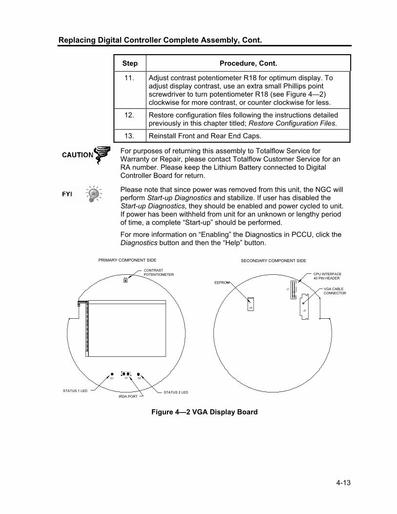
4-13
Replacing Digital Controller Complete Assembly, Cont.
Step Procedure, Cont.
11. Adjust contrast potentiometer R18 for optimum display. To adjust display contrast, use an extra small Phillips point screwdriver to turn potentiometer R18 (see Figure 4—2) clockwise for more contrast, or counter clockwise for less.
12. Restore configuration files following the instructions detailed previously in this chapter titled; Restore Configuration Files.
13. Reinstall Front and Rear End Caps.
For purposes of returning this assembly to Totalflow Service for Warranty or Repair, please contact Totalflow Customer Service for an RA number. Please keep the Lithium Battery connected to Digital Controller Board for return.
Please note that since power was removed from this unit, the NGC will perform Start-up Diagnostics and stabilize. If user has disabled the Start-up Diagnostics, they should be enabled and power cycled to unit. If power has been withheld from unit for an unknown or lengthy period of time, a complete “Start-up” should be performed.
For more information on “Enabling” the Diagnostics in PCCU, click the Diagnostics button and then the “Help” button.
PRIMARY COMPONENT SIDE SECONDARY COMPONENT SIDE
D1 U1 D2
R18
U2J2
J1 VGA CABLE CONNECTOR
CPU INTERFACE40 PIN HEADER
EEPROM
CONTRAST POTENTIOMETER
STATUS 1 LED STATUS 2 LEDIRDA PORT
Figure 4—2 VGA Display Board

4-14
Digital Controller Assembly Mounting Bracket
This section presents the procedures for removal and installation of the Digital Controller Assembly and Mounting Bracket. Access to the VGA Display board and the Digital Controller Board is gained by removing the front mounted assembly from the GC Module. If directed here from another procedure, return there when disassembly is complete.
As with all electronic components, caution should be used when handling boards. Static Electricity can potentially damage board components voiding any warranty.
Instructions
Step Procedure
1. On the Analyzer Operation screen, click Hold under Next Mode. When unit completes the current cycle and enters Hold, you may continue to the next step.
2. Gain access to Digital Controller Assembly by loosening the Countersunk Hex Socket Locking Set Screw in the front end cap using a 1/16” Hex wrench, then unscrewing the end cap.
3. Using a Flat Blade Screwdriver, loosen screw in Mounting Clamp (see Figure 4—1).
4. Unplug the Ground Cable (2015341-008) from the Digital Controller Assembly.
5. Slide assembly off of thermal flask, being careful to not unplug the flat ribbon cable connecting the Digital Controller Assembly to the Termination Panel or the Lithium Battery.
DO NOT remove the NGC Board mounted Lithium Battery or Termination Panel Cable at this time. Removing the Lithium Battery will cause a COLD start and that may not be desirable. When Replacing the Lithium Battery, the Termination Panel Cable must remain connected to power the Digital Controller Assembly otherwise unit will COLD Start. You will receive specific instructions during each procedure if either cable should be unplugged.
6. To reassemble, perform steps 3–5 in reverse order, being careful to align the display screen horizontally before tightening screw.

4-15
Replacing Display Board
The ¼ Panel VGA Board is mounted inside of NGC front end cap. To access and remove Display Board (P/N 2101984-xxx), perform the following procedures.
DO NOT remove the NGC Board mounted Lithium battery since it provides power to RAM. It is recommended that a Data Collect and backup be performed prior to accessing and removing any component to prevent potential loss of stored data.
Instructions
Step Procedure
1. On the Analyzer Operation screen, click Hold under Next Mode. When unit completes the current cycle and enters Hold, you may continue to the next step.
2. Collect data from unit.
3. Back up configuration files following the instructions detailed in this chapter titled; Backing Up Configuration Files.
4. Using Lithium Battery Status instructions, verify battery status is “OK” before proceeding.
5. Disconnect or remove Power from NGC unit externally or remove J1 connector from Termination Panel.
As with all electronic components, caution should be used when handling boards. Static Electricity can potentially damage board components voiding any warranty.
6. Gain access to Digital Controller Assembly by loosening the Countersunk Hex Socket Locking Set Screw in the front end cap using a 1/16” Hex wrench, then unscrewing the end cap.
7. Following the instructions detailed in this chapter titled; Digital Controller Assembly Mounting Bracket, remove assembly.
8. Carefully unplug the cable to the Termination Panel. DO NOT unplug the Lithium Battery, doing so will cause a COLD Start.
9. Using a ¼” Hex Nut Driver, remove the 6 Hex Nuts from the mounting bracket and lift bracket from standoffs.
10. Using a 3/16” Hex Nut Driver, remove the 6 Hex Standoffs holding the Digital Controller Board in place.
Continued on Next Page
4-16
Replacing Display Board, Cont.
Step Procedure, Cont.
11. Gently lift the Digital Controller Board off of the divider standoffs, being careful to separate the J2 LCD Interface connector without bending the connector pins. Set aside on an anti-static surface, being sure to leave the Lithium Battery connected.
12. Using a 3/16” Hex Nut Driver, remove the 6 Hex Standoffs holding the VGA Digital Controller Board in place.
13. Gently lift the VGA Display Board off of the mounting screws. Set aside on an anti-static surface.
14. Place new VGA Display Board on the Mounting Plate, being careful to align the board to the plate with the VGA screen rotated to fit the mounting plate cut away and the R18 Contrast Potentiometer aligned behind the access hole (see Figure 4—2).
15. To reassemble, perform steps 7–14 in reverse order. DO NOT over tighten screws.
Please note that Termination Panel to Digital Controller ribbon cable pin 1 wire is NOT red. On Digital Controller Board, the red edge (pin 1) of cable should plug onto Pin 50, the right side of plug. Plug is “keyed”, do not force plug into connector.
16. Once Display Board is reinstalled, apply power to NGC (Step 6).
17. Adjust contrast potentiometer R18 for optimum display. To adjust display contrast, use an extra small Phillips point screwdriver to turn potentiometer R18 (see Figure 4—2) clockwise for more contrast or counter clockwise for less.
For purposes of returning this board to Totalflow Service for Warranty or Repair, please contact Totalflow Customer Service for an RA number. Please keep the Lithium Battery connected to Digital Controller Board for return.
18. Reinstall Front and Rear End Caps.
Please note that since power was removed from this unit, the NGC will perform Start-up Diagnostics and stabilize. If user has disabled the Start-up Diagnostics, they should be enabled and power cycled to unit. If power has been withheld from unit for an unknown or lengthy period of time, a complete “Start-up” should be performed. For more information on “Enabling” the Diagnostics in PCCU, click the Diagnostics button and then the “Help” button.

4-17
Replacing Digital Controller Board
The Digital Controller Board (P/N 2101946-xxx) mounted inside of NGC front end cap. To access and remove this board, perform the following procedures.
It is recommended that a Data Collect and backup be performed prior to accessing and removing any component to prevent potential loss of stored data.
Instructions
Step Procedure
1. On the Analyzer Operation screen, click Hold under Next Mode. When unit completes the current cycle and enters Hold, you may continue to the next step.
2. Collect data from unit.
3. Back up configuration files following the instructions detailed previously in this chapter titled; Backing Up Configuration Files.
4. Using Lithium Battery Status instructions, verify battery status is “OK” before proceeding.
5. Disconnect or remove Power from NGC unit externally or remove J1 connector from Termination Panel.
As with all electronic components, caution should be used when handling boards. Static Electricity can potentially damage board components voiding any warranty.
6. Gain access to Digital Controller Assembly by loosening the Countersunk Hex Socket Locking Set Screw in the front end cap using a 1/16” Hex wrench, then unscrewing the end cap.
7. Following the instructions detailed previously in this chapter titled; Digital Controller Assembly Mounting Bracket, remove assembly.
8. Carefully unplug the cable to the Termination Panel, leaving the Lithium Battery plugged in (see Figure 4—3).
9. Using a ¼” Hex Nut Driver, remove the 6 Hex Nuts from the mounting bracket and lift bracket from standoffs.
10. Using a 3/16” Hex Nut Driver, remove the 6 Hex Standoffs holding the Digital Controller Board in place.
11. Gently lift the Digital Controller Board off of the divider standoffs, being careful to separate the J2 LCD Interface connector without bending the connector pins. Set aside on an anti-static surface with Lithium Battery plugged in.
Continued on Next Page

4-18
Replacing Digital Controller Board, Cont.
SECURE DIGITAL CARD DRIVE
JTAG INTERFACE14 PIN HEADER
AUXILIARY INTERFACE32 PIN CONNECTOR
3 PIN HEADERLITHIUM BATTER
TERMINATION INTERFACE50 PIN CONNECTOR
BOOT MODENOT USERCONFIGURABLE
LCD INTERFACE40 PIN CONNECTOR
CPU
J2
U11
U19U18
U20 U21
13
U10
1
J5
14
J7
J3
PRIMARY COMPONENT SIDE SECONDARY COMPONENT SIDE
3
J6
1
214
21
J15049
U14
U3
Figure 4—3 Digital Controller Board
Step Procedure, Cont.
12. On the replacement board, remove the Lithium Battery Connector from J5, turn connector over, shift up and reinsert so that plug covers all three pins (red wire up).
13. Place new Controller Board on the standoffs, being careful to align the J2 LCD Interface connection to the J1 pins on the VGA Display Board.
14. To reassemble, perform steps 7–10 in reverse order. DO NOT over tighten screws.
Please note that Termination Panel to Digital Controller ribbon cable pin 1 wire is NOT red. On Digital Controller Board, the red edge (pin 1) of cable should plug onto Pin 50, the right side of plug. Plug is “keyed”, do not force plug into connector.
15. Once Digital Controller Board is reinstalled, apply power to NGC (Step 6).
16. Reinstall Front and Rear End Caps.
For purposes of returning this board to Totalflow Service for Warranty or Repair, please contact Totalflow Customer Service for an RA number. Please keep the Lithium Battery connected to Digital Controller Board for return.
Please note that since power was removed from this unit, the NGC will perform Start-up Diagnostics and stabilize.

4-19
Replacing Analytical Module
This section presents the procedures for removal and installation of Analytical Module (P/N 2102172-xxx). The Module is a completely self-contained unit and is part of the NGC8200. Read through all procedural steps before beginning disassembly. Verify before beginning procedure that module is appropriately rated for the system voltage. Compare module voltage to ID tag located on the side of the enclosure.
When the Analytical Module is removed, the module should be placed on a clean dirt free work surface. Care should be taken that gas ports be free from lint or dust particles. Totalflow strongly suggests that the GC replacement module be kept in sealed static free envelope until the last possible moment before installation.
It is important that bottom surface of Module be placed on a clean lint free cloth to prevent components from being scratched, damaged or contaminated.
Instructions
Step Procedure
1. On the Analyzer Operation screen, click Hold under Next Mode. When unit completes the current cycle and enters Hold, you may continue to the next step.
2. Collect data from unit.
3. Back up configuration files following the instructions detailed previously in this chapter titled; Backing Up Configuration Files.
4. Using Lithium Battery Status instructions, verify battery status is “OK” before proceeding.
5. Turn off all Sample Streams, Calibration Gas and Carrier Gas.
6. Disconnect or remove Power from NGC unit externally or remove J1 connector from Termination Panel.
As with all electronic components, caution should be used when handling boards. Static Electricity can potentially damage board components voiding any warranty.
7. Gain access to Digital Controller Assembly by loosening the Countersunk Hex Socket Locking Set Screw in the front end cap using a 1/16” Hex wrench, then unscrewing the end cap.
8. Following the instructions detailed previously in this chapter titled; Digital Controller Assembly Mounting Bracket, remove assembly. If weather/circumstances permit, the Digital Controller Assembly may be suspended by the cables to eliminate stress on cable connections, you may skip to step 10.
Continued on Next Page

4-20
Replacing Analytical Module, Cont.
Step Procedure, Cont.
9. Carefully unplug the cable to the Termination Panel, leaving the Lithium Battery plugged in, set Digital Controller Assembly aside on a clean, lint-free surface.
10. Using a 5/16” Hex Wrench, loosen Mounting Screw (see Figure 4—4) holding Analytical Module in place until module can be slowly lifted from the enclosure, taking care to not pull or stress wires attached to the rear of the assembly.
11. Detach Analytical Module rear face jack J1 and J4 if Auxiliary Heater is installed (see Figure 4—5).
12. Set module on a clean, lint-free surface.
13. Verify that gasket on Feed-Through Assembly Manifold Interface is in place, in good condition and free from Metal filings or other contamination. If gasket has fallen off inside the enclosure or stuck to the GC Module, replace onto Feed-Through Manifold Interface ensuring that gasket does NOT cover the gas portholes.
14. Verify S1 Auxiliary Heater Switch is set to correct position. If using the Auxiliary Feed-Through Heater, set position to Normal.
15. Insert Mounting Screw into Analytical Module.
16. Holding new Analytical Module at the opening of the enclosure, reconnect jack J1 and J4 if Auxiliary Heater is installed (see Figure 4—5).
Figure 4—4 Analytical Module
Continued on Next Page

4-21
Replacing Analytical Module, Cont.
Figure 4—5 Analytical Processor Board
Step Procedure, Cont.
17. Carefully insert module into enclosure, rotating module to ensure rear components clear the Manifold Interface on the inside area of the Feed-Through Assembly. Feed-Through Manifold Interface and Analytical Module are keyed to ensure proper alignment.
18. When Analytical Module is in place, tighten Mounting Screw.
19. Reassemble Digital Controller Assembly using instructions previously covered in this chapter.
20. Plug Termination Panel to Digital Controller ribbon cable into Digital Controller assembly.
Please note that Termination Panel to Digital Controller ribbon cable pin 1 wire is NOT red. On Digital Controller Board, the red edge (pin 1) of cable should plug onto Pin 50, the right side of plug. Plug is “keyed”, do not force plug into connector.
21. Insert Lithium Battery pack into enclosure between enclosure and thermal flask.
22. Turn on all Sample Streams, Calibration Gas and Carrier Gas.
23. Once unit is reassembled, apply power to NGC (Step 6).
24. Follow Cold Start procedure in Chapter 4 Maintenance.
Continued on Next Page

4-22
Replacing Analytical Module, Cont.
Step Procedure, Cont.
25. Reinstall Front and Rear End Caps.
For purposes of returning this assembly to Totalflow Service for Warranty or Repair, please contact Totalflow Customer Service for an RA number.
Please note that since power was removed from this unit, the NGC will perform Start-up Diagnostics and stabilize. If user has disabled the Start-up Diagnostics, they should be enabled and power cycled to unit. If power has been withheld from unit for an unknown or lengthy period of time, a complete “Start-up” should be performed.
For more information on “Enabling” the Diagnostics in PCCU, click the Diagnostics button and then the “Help” button.
Replacing GC Module
This section presents the procedures for removal and installation of GC Module (P/N 2102033-xxx). The Module is a completely self-contained unit and is part of the Analytical Module. Read through all procedural steps before removing the assembly. Verify before beginning procedure that module is appropriately rated for the system voltage. Compare module voltage to ID tag located on the side of the enclosure.
When the GC Module is removed, the module should be placed on a clean dirt free work surface. It is important that bottom surface of Module be placed on a clean lint free cloth to prevent its base from being scratched or damaged and gas sample flow line openings free of foreign contaminants.
If the GC Module is not being immediately replaced, put the Thermal Flask back in place to prevent the mandrel from being scratched or damaged and gas sample flow line openings free of foreign contaminants. Also, be careful with the miniature “D” type connector pins.
Instructions
Step Procedure
1. On the Analyzer Operation screen, click Hold under Next Mode. When unit completes the current cycle and enters Hold, you may continue to the next step.
2. Collect data from unit.
3. Back up configuration files following the instructions detailed previously in this chapter titled; Backing Up Configuration Files.
Continued on Next Page

4-23
Replacing GC Module, Cont.
Step Procedure, Cont.
4. Using Lithium Battery Status instructions, verify battery status is “OK” before proceeding.
5. Turn off all Sample Streams, Calibration Gas and Carrier Gas.
6. Disconnect or remove Power from NGC unit externally or remove J1 connector from Termination Panel.
As with all electronic components, caution should be used when handling boards. Static Electricity can potentially damage board components voiding any warranty.
7. Gain access to Digital Controller Assembly by loosening the Countersunk Hex Socket Locking Set Screw in the front end cap using a 1/16” Hex wrench, then unscrewing the end cap.
8. Following the instructions detailed previously in this chapter titled; Digital Controller Assembly Mounting Bracket, remove assembly. If weather/circumstances permit, the Digital Controller Assembly may be suspended by the cables to eliminate stress on cable connections, you may skip to step 10.
9. Carefully unplug the cable to the Termination Panel, leaving the Lithium Battery plugged in, set Digital Controller Assembly aside on a clean, lint-free surface.
10. Unscrew Thermal Flask Counterclockwise (see Figure 4—6). When loose, lift flask from unit. Set aside.
11. Unscrew Oven Wall Counterclockwise (Oven Wall may be hot). When loose, lift cylinder from the GC Module. Set aside.
12. Using the Extraction Tool, remove cable connectors from J1, J2 and J3 jacks. DO NOT pull connectors from board by wires.
13. Using a 9/64” Hex Wrench, loosen the Mounting Screw inside the center of the assembly. When loose, lift assembly from Manifold Assembly. Set aside on a clean, lint-free surface.
14. Verify that Manifold Heater Plate gasket is in place and in good condition.
15. Carefully insert replacement module onto Manifold Assembly, rotating module to ensure key holes line up and module rests on the base. Unit should not turn once it is seated correctly.
16. When GC Module is in place, tighten Mounting Screw.
17. Carefully restore cable connectors to J1, J2 and J3 jacks, being careful to not press against the wires attached to the connector head.
Continued on Next Page

4-24
Replacing GC Module, Cont.
Figure 4—6 GC Module, Exploded View
Step Procedure, Cont.
18. Replace Oven Wall onto GC Module, being careful to not pinch or bind any of the cables. When fully on, turn Oven Wall clockwise to tighten.
19. Replace Thermal Flask over GC Module. When flask reaches mounting bracket, turn clockwise to tighten.
20. Reassemble Digital Controller Assembly using instructions previously covered in this chapter.
21. Plug Termination Panel to Digital Controller ribbon cable into Digital Controller assembly If disconnected.
Please note that Termination Panel to Digital Controller ribbon cable pin 1 wire is NOT red. On Digital Controller Board, the red edge (pin 1) of cable should plug onto Pin 50, the right side of plug. Plug is “keyed”, do not force plug into connector.
22. Insert Lithium Battery pack into enclosure between enclosure and thermal flask.
23. Turn on all Sample Streams, Calibration Gas and Carrier Gas.
Continued on Next Page

4-25
Replacing GC Module, Cont.
Step Procedure, Cont.
24. Once unit is reassembled, apply power to NGC (Step 6).
For purposes of returning this assembly to Totalflow Service for Warranty or Repair, please contact Totalflow Customer Service for an RA number.
25. Follow Cold Start procedure in Chapter 4 Maintenance.
26. Reinstall Front and Rear End Caps.
Please note that since power was removed from this unit, the NGC will perform Start-up Diagnostics and stabilize. If user has disabled the Start-up Diagnostics, they should be enabled and power cycled to unit. If power has been withheld from unit for an unknown or lengthy period of time, a complete “Start-up” should be performed.
For more information on “Enabling” the Diagnostics in PCCU, click the Diagnostics button and then the “Help” button.
Replacing Manifold Assembly
This section presents the procedures for removal and installation of Manifold Assembly (P/N 2102149-xxx). This assembly is part of the Analytical Module which contains the Analytical Processor Board. Read through all procedural steps before removing the assembly.
Instructions
Step Procedure
1. On the Analyzer Operation screen, click Hold under Next Mode. When unit completes the current cycle and enters Hold, you may continue to the next step.
2. Collect data from unit.
3. Back up configuration files following the instructions detailed previously in this chapter titled; Backing Up Configuration Files.
4. Using Lithium Battery Status instructions, verify battery status is “OK” before proceeding.
5. Turn off all Sample Streams, Calibration Gas and Carrier Gas.
6. Disconnect or remove Power from NGC unit externally or remove J1 connector from Termination Panel.
As with all electronic components, caution should be used when handling boards. Static Electricity can potentially damage board components voiding any warranty.
Continued on Next Page

4-26
Replacing Manifold Assembly, Cont.
Step Procedure, Cont.
7. Gain access to Digital Controller Assembly by loosening the Countersunk Hex Socket Locking Set Screw in the front end cap using a 1/16” Hex wrench, then unscrewing the end cap.
8. Following the instructions detailed previously in this chapter titled; Digital Controller Assembly Mounting Bracket, remove assembly. If weather/circumstances permit, the Digital Controller Assembly may be suspended by the cables to eliminate stress on cable connections, you may skip to step 10.
9. Carefully unplug the cable to the Termination Panel, leaving the Lithium Battery plugged in, set Digital Controller Assembly aside on a clean, lint-free surface.
10. Using a 5/16” Hex Wrench, loosen Mounting Screw holding Analytical Module in place until module can be slowly lifted from the enclosure, taking care to not pull wires attached to the rear of the assembly.
11. Detach Analytical Module rear face jack J1 and J4 if Auxiliary Heater is installed.
12. Set module on a clean, lint-free surface, with flask facing up.
13. Unscrew Thermal Flask Counterclockwise (see Figure 4—6). When loose, lift flask from the GC Module. Set aside.
14. Unscrew Oven Wall Counterclockwise. When loose, lift cylinder straight up off the GC Module. Set aside.
15. Using the Extraction Tool, remove cable connectors from J1, J2 and J3 jacks. DO NOT pull connectors from board by wires.
16. Using a 9/64” Hex Wrench, loosen the Mounting Screw inside the center of the assembly. When loose, lift assembly from Manifold Assembly. Set aside on a clean, lint-free surface.
17. Using a 7/64” Hex Wrench, loosen all five Hex Socket screws until loose.
18. When free, lift Manifold straight up away from the Analytical Processor Assembly (see Figure 4—7).
19. Carefully set replacement manifold onto Analytical Processor Assembly, rotating module to ensure screw holes line up with stand-offs, resting Manifold on the base.
20. Insert all five Hex Socket screws into Manifold screw holes.
Continued on Next Page
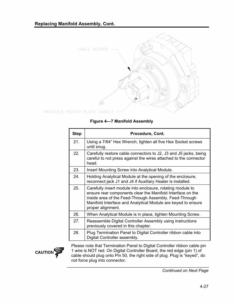
4-27
Replacing Manifold Assembly, Cont.
Figure 4—7 Manifold Assembly
Step Procedure, Cont.
21. Using a 7/64” Hex Wrench, tighten all five Hex Socket screws until snug.
22. Carefully restore cable connectors to J2, J3 and J5 jacks, being careful to not press against the wires attached to the connector head.
23. Insert Mounting Screw into Analytical Module. 24. Holding Analytical Module at the opening of the enclosure,
reconnect jack J1 and J4 if Auxiliary Heater is installed. 25. Carefully insert module into enclosure, rotating module to
ensure rear components clear the Manifold Interface on the inside area of the Feed-Through Assembly. Feed-Through Manifold Interface and Analytical Module are keyed to ensure proper alignment.
26. When Analytical Module is in place, tighten Mounting Screw. 27. Reassemble Digital Controller Assembly using instructions
previously covered in this chapter. 28. Plug Termination Panel to Digital Controller ribbon cable into
Digital Controller assembly.
Please note that Termination Panel to Digital Controller ribbon cable pin 1 wire is NOT red. On Digital Controller Board, the red edge (pin 1) of cable should plug onto Pin 50, the right side of plug. Plug is “keyed”, do not force plug into connector.
Continued on Next Page

4-28
Replacing Manifold Assembly, Cont.
Step Procedure, Cont.
29. Insert Lithium Battery pack into enclosure between enclosure and thermal flask.
30. Once unit is reassembled, apply power to NGC (Step 6). 31. Reinstall Front and Rear End Caps.
For purposes of returning this assembly to Totalflow Service for Warranty or Repair, please contact Totalflow Customer Service for an RA number.
Please note that since power was removed from this unit, the NGC will perform Start-up Diagnostics and stabilize. If user has disabled the Start-up Diagnostics, they should be enabled and power cycled to unit. If power has been withheld from unit for an unknown or lengthy period of time, a complete “Start-up” should be performed.
For more information on “Enabling” the Diagnostics in PCCU, click the Diagnostics button and then the “Help” button.
Replacing Analytical Processor Assembly
This section presents the procedures for removal and installation of Analytical Processor Assembly (P/N 2101831-xxx). This assembly is part of the Analytical Module which contains the Analytical Processor Board. Read through all procedural steps before removing the assembly.
Instructions
Step Procedure
1. On the Analyzer Operation screen, click Hold under Next Mode. When unit completes the current cycle and enters Hold, you may continue to the next step.
2. Collect data from unit.
3. Back up configuration files following the instructions detailed previously in this chapter titled; Backing Up Configuration Files.
4. Using Lithium Battery Status instructions, verify battery status is “OK” before proceeding.
5. Turn off all Sample Streams, Calibration Gas and Carrier Gas.
Continued on Next Page

4-29
Replacing Analytical Processor Assembly, Cont.
Step Procedure, Cont.
6. Disconnect or remove Power from NGC unit externally or remove J1 connector from Termination Panel.
As with all electronic components, caution should be used when handling boards. Static Electricity can potentially damage board components voiding any warranty.
7. Gain access to Digital Controller Assembly by loosening the Countersunk Hex Socket Locking Set Screw in the front end cap using a 1/16” Hex wrench, then unscrewing the end cap.
8. Following the instructions detailed previously in this chapter titled; Digital Controller Assembly Mounting Bracket, remove assembly. If weather/circumstances permit, the Digital Controller Assembly may be suspended by the cables to eliminate stress on cable connections, you may skip to step 10.
9. Carefully unplug the cable to the Termination Panel, leaving the Lithium Battery plugged in, set Digital Controller Assembly aside on a clean, lint-free surface.
10. Using a 5/16” Hex Wrench, loosen Mounting Screw holding Analytical Module in place until module can be slowly lifted from the enclosure, taking care to not pull wires attached to the rear of the assembly.
11. Detach Analytical Module rear face jack J1 and J4 if Auxiliary Heater is installed.
If cable removed from J4 jack (Auxiliary Heater) care must be taken to verify or set S1 Auxiliary Temperature Override Switch on Primary component Side of Electronic Board.
12. Set module on a clean, lint-free surface, with flask facing up.
13. Using the Extraction Tool, remove cable connectors from J2, J3 and J5 jacks (see Figure 4—5). DO NOT pull connectors from board by wires.
14. Prepare replacement assembly by removing the clean static-free packaging. Set assembly on a clean lint-free surface with the stand-offs facing up.
15. Using a 7/64” Hex Wrench, loosen all five Hex Socket screws, located on the Manifold Assembly, until loose.
16. When free, lift Manifold and upper assemblies straight up away from the Analytical Processor Assembly (see Figure 4—8). As screws and washers are in-set in the Manifold Assembly, take care to not tip assembly and loose them.
Continued on Next Page

4-30
Replacing Analytical Processor Assembly, Cont.
Figure 4—8 Analytical Processor Assembly, Exploded from Manifold
Step Procedure, Cont.
17. On replacement Analytical Processor Assembly, verify switch S1 Auxiliary Temperature Override setting. If J4 cable was detached in Step 11, switch must be set to NORM. If no cable was detached, switch must be set to OVERRIDE.
18. Move Manifold and upper assembly to the replacement Analytical Processor Assembly and rest on top of the stand-offs, rotating unit to align Assembly cut-away with the Mounting Screw on the Analytical Module and screw holes.
19. Using a 7/64” Hex Wrench, tighten all five Hex Socket screws until snug.
20. Carefully restore cable connectors to J2, J3 and J5, being careful to not press against the wires attached to the connector head.
21. Insert Mounting Screw into Analytical Module.
22. Holding Analytical Module at the opening of the enclosure, reconnect jack J1 and J4 if Auxiliary Heater is installed.
Continued on Next Page

4-31
Replacing Analytical Processor Assembly, Cont.
Step Procedure, Cont.
23. Carefully insert module into enclosure, rotating module to ensure rear components clear the Manifold Interface on the inside area of the Feed-Through Assembly. Feed-Through Manifold Interface and Analytical Module are keyed to ensure proper alignment.
24. When Analytical Module is in place, tighten Mounting Screw.
25. Reassemble Digital Controller Assembly using instructions previously covered in this chapter.
26. Plug Termination Panel to Digital Controller ribbon cable into Digital Controller assembly.
Please note that Termination Panel to Digital Controller ribbon cable pin 1 wire is NOT red. On Digital Controller Board, the red edge (pin 1) of cable should plug onto Pin 50, the right side of plug. Plug is “keyed”, do not force plug into connector.
27. Insert Lithium Battery pack into enclosure between enclosure and thermal flask.
28. Once unit is reassembled, apply power to NGC (Step 6).
29. Reinstall Front and Rear End Caps.
For purposes of returning this assembly to Totalflow Service for Warranty or Repair, please contact Totalflow Customer Service for an RA number.
Please note that since power was removed from this unit, the NGC will perform Start-up Diagnostics and stabilize. If user has disabled the Start-up Diagnostics, they should be enabled and power cycled to unit. If power has been withheld from unit for an unknown or lengthy period of time, a complete “Start-up” should be performed.
For more information on “Enabling” the Diagnostics in PCCU, click the Diagnostics button and then the “Help” button.
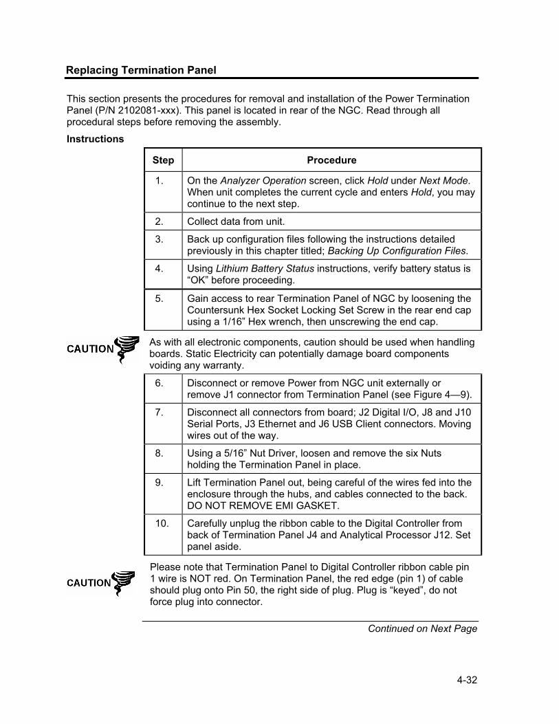
4-32
Replacing Termination Panel
This section presents the procedures for removal and installation of the Power Termination Panel (P/N 2102081-xxx). This panel is located in rear of the NGC. Read through all procedural steps before removing the assembly.
Instructions
Step Procedure
1. On the Analyzer Operation screen, click Hold under Next Mode. When unit completes the current cycle and enters Hold, you may continue to the next step.
2. Collect data from unit.
3. Back up configuration files following the instructions detailed previously in this chapter titled; Backing Up Configuration Files.
4. Using Lithium Battery Status instructions, verify battery status is “OK” before proceeding.
5. Gain access to rear Termination Panel of NGC by loosening the Countersunk Hex Socket Locking Set Screw in the rear end cap using a 1/16” Hex wrench, then unscrewing the end cap.
As with all electronic components, caution should be used when handling boards. Static Electricity can potentially damage board components voiding any warranty.
6. Disconnect or remove Power from NGC unit externally or remove J1 connector from Termination Panel (see Figure 4—9).
7. Disconnect all connectors from board; J2 Digital I/O, J8 and J10 Serial Ports, J3 Ethernet and J6 USB Client connectors. Moving wires out of the way.
8. Using a 5/16” Nut Driver, loosen and remove the six Nuts holding the Termination Panel in place.
9. Lift Termination Panel out, being careful of the wires fed into the enclosure through the hubs, and cables connected to the back. DO NOT REMOVE EMI GASKET.
10. Carefully unplug the ribbon cable to the Digital Controller from back of Termination Panel J4 and Analytical Processor J12. Set panel aside.
Please note that Termination Panel to Digital Controller ribbon cable pin 1 wire is NOT red. On Termination Panel, the red edge (pin 1) of cable should plug onto Pin 50, the right side of plug. Plug is “keyed”, do not force plug into connector.
Continued on Next Page

4-33
Replacing Termination Panel, Cont.
PRIMARY COMPONENT SIDE SECONDARY COMPONENT SIDE
VR1S2
UN
SEC
UR
E
SECURITY ENABLED
STATUS
(-)(+)
J4ANALYTICAL PROCESSORCONNECTION
DIGITAL CONTROLLERCONNECTION
USB CLIENT RECEPTICAL
ETHERNET STATUS INDICATORSRESET
USB HOST RECEPTICAL
SERIAL PORT 1
SERIAL PORT 1 TERMINATION
LOCAL SERIAL DATA CONNECTION
SECURITY SWITCH
DIGITAL I/O
POWER
ETHERNET RECEPTICAL
SERIAL PORT 2 TERMINATION
SERIAL PORT 2
VOLTAGE REGULATOR
SECURITY SWITCH STATUS
OUTPUTS
D4
(-)
2
(-)(+)
J7
POWER
D1
J9
D3
D25VDC
J2
J1
J6
1
J8
J5
32 54 76 98
D12 D11
J31 3
D13 S1
LINKLANSTAT
41 32 5 6 87
J109
J111 3
INPUTS
(-)(-)
1
(+)
2
(+)
1
(+)
J12
Figure 4—9 Termination Panel
Step Procedure, Cont.
11. Holding replacement panel at the opening of the enclosure, reconnect ribbon cable to the Digital Controller into the back of the Termination Panel J4 and the Analytical Processor cable into J12.
12. Insert Termination Panel into enclosure being careful to not pinch wires between mounting stud and panel.
13. Replace Nuts to hold Termination Panel in place.
14. Restore J2, J8, J10, J3 and J6 connections if applicable.
15. Once unit is reassembled, apply power to NGC (Step 6).
16. Reinstall Front and Rear End Caps.
For purposes of returning this assembly to Totalflow Service for Warranty or Repair, please contact Totalflow Customer Service for an RA number.
Please note that since power was removed from this unit, the NGC will perform Start-up Diagnostics and stabilize. If user has disabled the Start-up Diagnostics, they should be enabled and power cycled to unit. If power has been withheld from unit for an unknown or lengthy period of time, a complete “Start-up” should be performed.
For more information on “Enabling” the Diagnostics in PCCU, click the Diagnostics button and then the “Help” button.
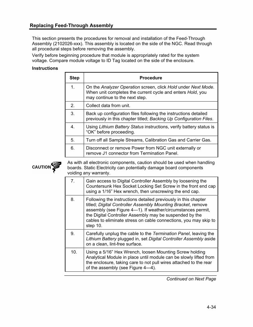
4-34
Replacing Feed-Through Assembly
This section presents the procedures for removal and installation of the Feed-Through Assembly (2102026-xxx). This assembly is located on the side of the NGC. Read through all procedural steps before removing the assembly. Verify before beginning procedure that module is appropriately rated for the system voltage. Compare module voltage to ID Tag located on the side of the enclosure.
Instructions
Step Procedure
1. On the Analyzer Operation screen, click Hold under Next Mode. When unit completes the current cycle and enters Hold, you may continue to the next step.
2. Collect data from unit.
3. Back up configuration files following the instructions detailed previously in this chapter titled; Backing Up Configuration Files.
4. Using Lithium Battery Status instructions, verify battery status is “OK” before proceeding.
5. Turn off all Sample Streams, Calibration Gas and Carrier Gas.
6. Disconnect or remove Power from NGC unit externally or remove J1 connector from Termination Panel.
As with all electronic components, caution should be used when handling boards. Static Electricity can potentially damage board components voiding any warranty.
7. Gain access to Digital Controller Assembly by loosening the Countersunk Hex Socket Locking Set Screw in the front end cap using a 1/16” Hex wrench, then unscrewing the end cap.
8. Following the instructions detailed previously in this chapter titled; Digital Controller Assembly Mounting Bracket, remove assembly (see Figure 4—1). If weather/circumstances permit, the Digital Controller Assembly may be suspended by the cables to eliminate stress on cable connections, you may skip to step 10.
9. Carefully unplug the cable to the Termination Panel, leaving the Lithium Battery plugged in, set Digital Controller Assembly aside on a clean, lint-free surface.
10. Using a 5/16” Hex Wrench, loosen Mounting Screw holding Analytical Module in place until module can be slowly lifted from the enclosure, taking care to not pull wires attached to the rear of the assembly (see Figure 4—4).
Continued on Next Page

4-35
Replacing Feed-Through Assembly, Cont.
Step Procedure, Cont.
11. Detach Analytical Module rear face jack J1 and J4 if Auxiliary Heater is installed.
12. Set module on a clean, lint-free surface.
13. Using a ¼” Open End Wrench, loosen Valco Nut and remove input line. Repeat for all Sample, Carrier and Calibration gas lines.
14. Using a 5/64” Hex Wrench, loosen Feed-Through Set Screw.
15. Unscrew Feed-Through assembly, turning by hand Counterclockwise until free.
16. On replacement assembly, verify O-Ring and Feed-Through Manifold Gasket are in place and not damaged (see Figure 4—10).
17. Carefully apply Sealing Thread Lubricant to threads on Feed-Through assembly, being extremely careful to not contaminate Feed-Through Manifold and gasket.
18. Insert replacement Feed-Through assembly through opening and screw in Clockwise until completely screwed in but not tight.
19. Reverse direction unscrewing Feed-Through Assembly Counter Clockwise a MINIMUM of 1/2 rotation but NO more than 1 1/2 rotations, stopping when flat edge is exactly on top and horizontal.
SILICONE O-RING
FEED-THROUGH MANIFOLD GASKET
Flat Surface
Figure 4—10 Feed-Through Assembly
Continued on Next Page

4-36
Replacing Feed-Through Assembly, Cont.
Step Procedure, Cont.
20. Using a 5/64” Hex Wrench, tighten Feed-Through Set Screw.
21. Insert Mounting Screw into Analytical Module.
22. Holding Analytical Module at the opening of the enclosure, reconnect jack J1 and J4 if Auxiliary Heater is installed (see Figure 4—5).
23. Carefully insert module into enclosure, rotating module to ensure rear components clear the Manifold Interface on the inside area of the Feed-Through Assembly. Feed-Through Manifold Interface and Analytical Module are keyed to ensure proper alignment.
24. When Analytical Module is in place, tighten Mounting Screw.
25. Reassemble Digital Controller Assembly using instructions previously covered in this chapter.
26. Plug Termination Panel to Digital Controller ribbon cable into Digital Controller assembly.
Please note that Termination Panel to Digital Controller ribbon cable pin 1 wire is NOT red. On Digital Controller Board, the red edge (pin 1) of cable should plug onto Pin 50, the right side of plug. Plug is “keyed”, do not force plug into connector.
27. Insert Lithium Battery pack into enclosure between enclosure and thermal flask.
28. Once unit is reassembled, apply power to NGC (Step 6).
29. Reinstall Front and Rear End Caps.
Please note that since power was removed from this unit, the NGC will perform Start-up Diagnostics and stabilize. If user has disabled the Start-up Diagnostics, they should be enabled and power cycled to unit. If power has been withheld from unit for an unknown or lengthy period of time, a complete “Start-up” should be performed.
For more information on “Enabling” the Diagnostics in PCCU, click the Diagnostics button and then the “Help” button.

4-37
Replacing Lithium Battery
This section presents the procedures for removal and installation of a new Lithium Battery (P/N 1801337-xxx). The Lithium Battery is inside of the front end cap and is wedged between the Thermal Flask and the Enclosure wall. Read through all procedural steps before removing the assembly.
Instructions
Step Procedure
DO NOT REMOVE POWER TO UNIT! Loss of power to unit will perform a COLD Start. All data and configuration files will be destroyed.
1. On the Analyzer Operation screen, click Hold under Next Mode. When unit completes the current cycle and enters Hold, you may continue to the next step.
2. Collect data from unit.
3. Back up configuration files following the instructions detailed previously in this chapter titled; Backing Up Configuration Files.
As with all electronic components, caution should be used when handling boards. Static Electricity can potentially damage board components voiding any warranty.
4. Gain access to Digital Controller Assembly by loosening the Countersunk Hex Socket Locking Set Screw in the front end cap using a 1/16” Hex wrench, then unscrewing the end cap.
5. Unplug Lithium Battery connector from the J5 receptacle on Digital Controller Board (see Figure 4—11).
6. Plug in replacement Lithium Battery to J5 on Digital Controller Board.
7. Insert Lithium Battery pack into enclosure between enclosure and thermal flask.
8. Using Lithium Battery Status instructions, verify battery status is “OK” before proceeding.
9. Reinstall Front End Cap.
Continued on Next Page

4-38
Replacing Lithium Battery, Cont.
3
J6
1
214
21
J15049
U14
U3
J2
U11
U19U18
U20 U21
13
U10
1
J5
14
J7
SECURE DIGITAL CARD DRIVE
JTAG INTERFACE14 PIN HEADER
3 PIN HEADERLITHIUM BATTER
TERMINATION INTERFACE50 PIN CONNECTOR
BOOT MODENOT USERCONFIGURABLE
LCD INTERFACE40 PIN CONNECTOR
CPU
Figure 4—11 Primary Component Side Digital Controller Board
Replacing Frit Filters
Several reasons exist for replacing the Frit Filters (P/N 1800512-xxx); from a scheduled maintenance procedure to decreased sample pressure due to clogged filters. When replacing the filters on a regularly scheduled maintenance plan, it will most likely not require that the sample lines be removed from the external plate. When replacing the filters as a troubleshooting result, you should remove the sample input lines and use compressed air to clear the pathway. For the purpose of being thorough, these instructions contain steps for the worst case scenario.
Instructions
Step Procedure
1. On the Analyzer Operation screen, click Hold under Next Mode. When unit completes the current cycle and enters Hold, you may continue to the next step.
2. Collect data from unit.
Continued on Next Page

4-39
Replacing Frit Filters, Cont.
Step Procedure, Cont.
3. Back up configuration files following the instructions detailed previously in this chapter titled; Backing Up Configuration Files.
4. Turn off all Sample Streams, Calibration Gas and Carrier Gas.
5. Using a 7/32” Hex wrench, loosen and remove all 8–¼” Hex Socket Screws (see Figure 4—12).
6. If space permits, lift External plate away from internal plate and view the Frit Filters. If space does not permit lifting the plate away enough to view the filters, you must remove the Sample Input lines and the Carrier and Calibration Gas lines. If filters appear soiled, it will be necessary to remount the external plate and remove the input lines. To remove the input lines continue to the next step, otherwise skip to Step 8.
7. Using a ¼” Open End Wrench, loosen Valco Nut and remove input line. Repeat for all Sample, Carrier and Calibration gas lines.
OPTIONAL FEED-THROUGH HEATER CABLE
.5 MICRON INPUT FRIT FILTERS
FEED-THROUGH INTERFACE GASKET
SILICONE O-RING
EXTERNAL PLATE
MOUNTING HOLES FOR 1/4" SST HEX SOCKET SCREWS
INTERNAL PLATE
FEED-THROUGH MANIFOLD GASKET
Figure 4—12 Feed-Through Assembly, Exploded View
Continued on Next Page
4-40
Replacing Frit Filters, Cont.
Step Procedure, Cont.
8. Remove the 8–¼” Hex Socket Mounting Screws.
9. Remove the used filters from the filter sockets. Using an edged instrument, or possibly your fingernail, put pressure on the outermost edge of each filter to pop them out.
10. If replacing filters due to clogging, you should also use compressed air to blow out the input holes in the External Plate. It may also be necessary to wipe clean the gasket located on the internal plate. Otherwise, skip to the next step.
11. Using replacement filter, carefully lay filter into filter socket applying uniform pressure to filter. DO NOT use any pointed instrument to push filter into place. Repeat for each Input Stream, Carrier and Calibration Gas input. Vents do not require filters.
12. Reseat External Plate, aligning the mounting pins on the Internal Plate to the corresponding holes on the External Plate.
13. Replace the 8–¼” Mounting Screws, using a star pattern when tightening the screws.
14. If Sample, Carrier and Calibration Gas Lines were removed, purge air from the transport tubing and reconnect to corresponding ports.
DO NOT over tighten. After securing tubing, check for gas leaks.
Replacing Feed-Through Interface Gasket
Should the Feed-Through Interface Gasket (P/N 2102083-xxx) require replacement (see Figure 4—12), follow these instructions. Typically you would change the gasket while performing another procedure, but for the purposes of this manual, the instructions will start and finish as a complete procedure.
Instructions
Step Procedure
1. On the Analyzer Operation screen, click Hold under Next Mode. When unit completes the current cycle and enters Hold, you may continue to the next step.
2. Collect data from unit.
Continued on Next Page

4-41
Replacing Feed-Through Interface Gasket, Cont.
Step Procedure, Cont.
3. Back up configuration files following the instructions detailed previously in this chapter titled; Backing Up Configuration Files.
4. Turn off all Sample Streams, Calibration Gas and Carrier Gas.
5. Using a 7/32” Hex wrench, loosen and remove all 8–¼” Hex Socket Screws.
6. If space permits, lift External plate away from internal plate and remove the damaged Gasket from the Internal Plate. If space does not permit lifting the plate away enough to replace the Gasket, you must remove the Sample Input lines and the Carrier and Calibration Gas lines. Remount the external plate and remove the input lines. To remove the input lines continue to the next step, otherwise skip to Step 8.
7. Using a ¼” Open End Wrench, loosen Valco Nut and remove input line. Repeat for all Sample, Carrier and Calibration gas lines.
8. Remove the 8–¼” Hex Socket Mounting Screws.
9. Remove the damaged gasket from the Internal Plate.
10. Clean Gasket area on the Internal Plate using a clean, dry lint-free cloth before placing new Gasket on Internal Plate. Gasket is keyed to ensure that it is placed correctly. Gasket should not cover any holes in the internal plate.
11. Reseat External Plate, aligning the mounting pins on the Internal Plate to the corresponding holes on the External Plate.
12. Replace the 8–¼” Mounting Screws, using a star pattern when tightening the screws.
13. If Sample, Carrier and Calibration Gas Lines were removed, purge air from the transport tubing and reconnect to corresponding ports.
DO NOT over tighten. After securing tubing, check for gas leaks.

4-42
Replacing Feed-Through Manifold Gasket
Should the Feed-Through Manifold Gasket (P/N 2102082-xxx) require replacement (see Figure 4—12), follow these instructions. Typically you would change the gasket while performing another procedure, but for the purposes of this manual, the instructions will start and finish as a complete procedure.
Instructions
Step Procedure
1. On the Analyzer Operation screen, click Hold under Next Mode. When unit completes the current cycle and enters Hold, you may continue to the next step.
2. Collect data from unit.
3. Back up configuration files following the instructions detailed previously in this chapter titled; Backing Up Configuration Files.
4. Using Lithium Battery Status instructions, verify battery status is “OK” before proceeding.
5. Turn off all Sample Streams, Calibration Gas and Carrier Gas.
6. Disconnect or remove Power from NGC unit externally or remove J1 connector from Termination Panel.
As with all electronic components, caution should be used when handling boards. Static Electricity can potentially damage board components voiding any warranty.
7. Gain access to Digital Controller Assembly by loosening the Countersunk Hex Socket Locking Set Screw in the front end cap using a 1/16” Hex wrench, then unscrewing the end cap.
8. Following the instructions detailed previously in this chapter titled; Digital Controller Assembly Mounting Bracket, remove assembly (see Figure 4—1). If weather/circumstances permit, the Digital Controller Assembly may be suspended by the cables to eliminate stress on cable connections, you may skip to step 10.
9. Carefully unplug the cable to the Termination Panel, leaving the Lithium Battery plugged in, set Digital Controller Assembly aside on a clean, lint-free surface.
10. Using a 5/16” Hex Wrench, loosen Mounting Screw holding Analytical Module in place until module can be slowly lifted from the enclosure, taking care to not pull wires attached to the rear of the assembly (see Figure 4—4).
11. Detach Analytical Module rear face jack J1 and J4 if Auxiliary Heater is installed.
Continued on Next Page

4-43
Replacing Feed-Through Manifold Gasket, Cont.
Step Procedure, Cont.
12. Set module on a clean, lint-free surface.
13. Replace gasket on Feed-Through Assembly Manifold Interface ensuring that gasket does NOT cover the gas portholes.
14. Insert Mounting Screw into Analytical Module.
15. Holding Analytical Module at the opening of the enclosure, reconnect jack J1 and J4 if Auxiliary Heater is installed (see Figure 4—5).
16. Carefully insert module into enclosure, rotating module to ensure rear components clear the Manifold Interface on the inside area of the Feed-Through Assembly. Feed-Through Manifold Interface and Analytical Module are keyed to ensure proper alignment.
17. When Analytical Module is in place, tighten Mounting Screw.
18. Reassemble Digital Controller Assembly using instructions previously covered in this chapter.
19. Plug Termination Panel to Digital Controller ribbon cable into Digital Controller assembly.
Please note that Termination Panel to Digital Controller ribbon cable pin 1 wire is NOT red. On Digital Controller Board, the red edge (pin 1) of cable should plug onto Pin 50, the right side of plug. Plug is “keyed”, do not force plug into connector.
20. Insert Lithium Battery pack into enclosure between enclosure and thermal flask.
21. Once unit is reassembled, apply power to NGC (Step 6).
22. Reinstall Front and Rear End Caps.
Please note that since power was removed from this unit, the NGC will perform Start-up Diagnostics and stabilize. If user has disabled the Start-up Diagnostics, they should be enabled and power cycled to unit. If power has been withheld from unit for an unknown or lengthy period of time, a complete “Start-up” should be performed.
For more information on “Enabling” the Diagnostics in PCCU, click the Diagnostics button and then the “Help” button.

4-44
Replacing Termination Panel to Digital Controller Cable
Should the Termination Panel to Digital Controller Cable (P/N 1801513-xxx) become damaged and require replacement, follow these instructions. Typically you would change the cable while performing another procedure, but for the purposes of this manual, the instructions will start and finish as a complete procedure.
Instructions
Step Procedure
1. On the Analyzer Operation screen, click Hold under Next Mode. When unit completes the current cycle and enters Hold, you may continue to the next step.
2. Collect data from unit.
3. Back up configuration files following the instructions detailed previously in this chapter titled; Backing Up Configuration Files.
4. Using Lithium Battery Status instructions, verify battery status is “OK” before proceeding.
5. Turn off all Sample Streams, Calibration Gas and Carrier Gas.
6. Disconnect or remove Power from NGC unit externally or remove J1 connector from Termination Panel.
As with all electronic components, caution should be used when handling boards. Static Electricity can potentially damage board components voiding any warranty.
7. Gain access to Digital Controller Assembly by loosening the Countersunk Hex Socket Locking Set Screw in the front end cap using a 1/16” Hex wrench, then unscrewing the end cap.
8. Following the instructions detailed previously in this chapter titled; Digital Controller Assembly Mounting Bracket, remove assembly (see Figure 4—1).
9. Carefully unplug the cable to the Termination Panel, leaving the Lithium Battery plugged in, set Digital Controller Assembly aside on a clean, lint-free surface.
10. Using a 5/16” Hex Wrench, loosen Mounting Screw holding Analytical Module in place until module can be slowly lifted from the enclosure, taking care to not pull wires attached to the rear of the assembly (see Figure 4—4).
11. Detach Analytical Module rear face jack J1 and J4 if Auxiliary Heater is installed.
12. Set module on a clean, lint-free surface.
Continued on Next Page

4-45
Replacing Termination Panel to Digital Controller Cable, Cont.
Step Procedure, Cont.
13. Reach into enclosure through the front opening and unplug the ribbon cable from the rear of the Termination Panel J4.
14. On the replacement cable verify orientation by viewing the keyed receptacle on the Termination Panel and cable, insert plug into J4 connector.
15. Verify that gasket on Feed-Through Assembly Manifold Interface is in place and in good condition. If gasket has fallen off inside the enclosure or stuck to the GC Module, replace onto Feed-Through Manifold Interface ensuring that gasket does NOT cover the gas portholes.
16. Insert Mounting Screw into Analytical Module.
17. Holding Analytical Module at the opening of the enclosure, reconnect jack J1 and J4 if Auxiliary Heater is installed.
18. Carefully insert module into enclosure, rotating module to ensure rear components clear the Manifold Interface on the inside area of the Feed-Through Assembly. Feed-Through Manifold Interface and Analytical Module are keyed to ensure proper alignment.
19. When Analytical Module is in place, tighten Mounting Screw.
20. Reassemble Digital Controller Assembly using instructions previously covered in this chapter.
21. Plug Termination Panel to Digital Controller ribbon cable into Digital Controller assembly.
Please note that Termination Panel to Digital Controller ribbon cable pin 1 wire is NOT red. On Digital Controller Board, the red edge (pin 1) of cable should plug onto Pin 50, the right side of plug. Plug is “keyed”, do not force plug into connector.
22. Insert Lithium Battery pack into enclosure between enclosure and thermal flask.
23. Once unit is reassembled, apply power to NGC (Step 6).
24. Reinstall Front and Rear End Caps.
Please note that since power was removed from this unit, the NGC will perform Start-up Diagnostics and stabilize. If user has disabled the Start-up Diagnostics, they should be enabled and power cycled to unit. If power has been withheld from unit for an unknown or lengthy period of time, a complete “Start-up” should be performed. For more information on “Enabling” the Diagnostics in PCCU, click the Diagnostics button and then the “Help” button.

4-46
Replacing Analytical Processor to GC Module Cable
Should the Analytical Processor to GC Module Cable (P/N 2101816-xxx) become damaged and require replacement, follow these instructions. Typically you would change the cable while performing another procedure, but for the purposes of this manual, the instructions will start and finish as a complete procedure.
Instructions
Step Procedure
1. On the Analyzer Operation screen, click Hold under Next Mode. When unit completes the current cycle and enters Hold, you may continue to the next step.
2. Collect data from unit.
3. Back up configuration files following the instructions detailed previously in this chapter titled; Backing Up Configuration Files.
4. Using Lithium Battery Status instructions, verify battery status is “OK” before proceeding.
5. Turn off all Sample Streams, Calibration Gas and Carrier Gas.
6. Disconnect or remove Power from NGC unit externally or remove J1 connector from Termination Panel.
As with all electronic components, caution should be used when handling boards. Static Electricity can potentially damage board components voiding any warranty.
7. Gain access to Digital Controller Assembly by loosening the Countersunk Hex Socket Locking Set Screw in the front end cap using a 1/16” Hex wrench, then unscrewing the end cap.
8. Following the instructions detailed previously in this chapter titled; Digital Controller Assembly Mounting Bracket, remove assembly (see Figure 4—1).
9. Carefully unplug the cable to the Termination Panel, leaving the Lithium Battery plugged in, set Digital Controller Assembly aside on a clean, lint-free surface.
10. Using a 5/16” Hex Wrench, loosen Mounting Screw holding Analytical Module in place until module can be slowly lifted from the enclosure, taking care to not pull wires attached to the rear of the assembly (see Figure 4—4).
11. Detach Analytical Module rear face jack J1 and J4 if Auxiliary Heater is installed.
Continued on Next Page

4-47
Replacing Analytical Processor to GC Module Cable, Cont.
Step Procedure, Cont.
12. Set module on a clean, lint-free surface, with flask facing up.
13. Unscrew Thermal Flask Counterclockwise (see Figure 4—6). When loose, lift flask from the GC Module. Set aside.
14. Unscrew Oven Wall Counterclockwise. When loose, lift cylinder straight up off the GC Module. Set aside.
15. Using the Extraction Tool, remove cable connectors from J1, J2 and J3 jacks. DO NOT pull connectors from board by wires.
16. Using Extraction Tool, remove cable from Analytical Processor Assembly J2.
17. Locate cable keeper and remove from manifold.
18. Cut Cable Tie from Manifold Insulator.
19. Using a 9/64” Hex Wrench, loosen the Mounting Screw inside the center of the GC Module. When loose, lift assembly from Manifold Assembly Heater Plate. Set aside on a clean, lint-free surface.
20. Using 7/64” Hex Wrench, loosen 5 screws holding Manifold Heater Plate in place. Lift off, but do not disconnect Heater cable.
21. Using a 7/64” Hex Wrench, loosen and remove the 6 screws on the Retaining Ring that holds the Thermal Flask Mounting Cap in place.
22. Lift Retaining Ring and Mounting Cap off of Manifold Insulator.
23. Using Diagonal Cutters, cut final Cable Tie holding Cable to Manifold.
24. On replacement cable, use a ruler to measure exactly 6.5” from the 20 Pin Header on the divided end of the cable and mark.
25. Using a 3-7/8” Nylon Cable Tie, insert through holes on both sides of the Cutaway area on the Manifold, keeping Cable Tie Union on the underside of the Manifold Plate with cable running beneath the Cable Tie on the top and bottom of the Manifold Plate and the measured mark on the cable directly underneath the Cable Tie on the topside of the Manifold Plate. Tighten.
Continued on Next Page

4-48
Replacing Analytical Processor to GC Module Cable, Cont.
Step Procedure, Cont.
26. Feed cable through Thermal Flask cap and retaining ring.
27. Insert screws into retaining ring and start but do not tighten.
28. Ensure cables lay down into cable troughs and tighten retaining ring screws.
29. Lift cable and Heater Assembly Cable up along side of the Manifold Insulator, encircle with 5-5/8” Nylon Cable Tie and tighten tie into upper lip.
30. Using 7/64” Hex Wrench, reattach Manifold Heater Plate, tightening all 5 screws.
31. Reinstall cable keeper being careful that 2-wire Temperature Sensor is behind keeper with ribbon cable.
32. Carefully insert GC Module onto Manifold Heater Plate, rotating module to ensure key holes line up and module rests on the base. Unit should not turn once it is seated correctly.
33. When GC Module is in place, tighten Mounting Screw.
34. Carefully restore cable connectors to J1, J2 and J3 jacks, being careful to not press against the wires attached to the connector head.
35. Reattach ribbon cable to J2 located on the Analytical Processor Board facing the Manifold Assembly.
36. Replace Oven Wall onto GC Module, being careful to not pinch or bind any of the cables. When fully on, turn Oven Wall clockwise to tighten.
37. Replace Thermal Flask over GC Module. When flask reaches mounting bracket, turn clockwise to tighten.
38. Insert Mounting Screw into Analytical Module.
39. Holding Analytical Module at the opening of the enclosure, reconnect jack J1 and J4 if Auxiliary Heater is installed.
40. Carefully insert Analytical Module into enclosure, rotating module to ensure rear components clear the Manifold Interface on the inside area of the Feed-Through Assembly. Feed-Through Manifold Interface and Analytical Module are keyed to ensure proper alignment.
41. When Analytical Module is in place, tighten Mounting Screw.
Continued on Next Page

4-49
Replacing Analytical Processor to GC Module Cable, Cont.
Step Procedure, Cont.
42. Reassemble Digital Controller Assembly using instructions previously covered in this chapter.
43. Plug Termination Panel to Digital Controller ribbon cable into Digital Controller assembly.
Please note that Termination Panel to Digital Controller ribbon cable pin 1 wire is NOT red. On Digital Controller Board, the red edge (pin 1) of cable should plug onto Pin 50, the right side of plug. Plug is “keyed”, do not force plug into connector.
44. Insert Lithium Battery pack into enclosure between enclosure and thermal flask.
45. Once unit is reassembled, apply power to NGC (Step 6).
For purposes of returning this assembly to Totalflow Service for Warranty or Repair, please contact Totalflow Customer Service for an RA number.
46. Reinstall Front and Rear End Caps.
Please note that since power was removed from this unit, the NGC will perform Start-up Diagnostics and stabilize. If user has disabled the Start-up Diagnostics, they should be enabled and power cycled to unit. If power has been withheld from unit for an unknown or lengthy period of time, a complete “Start-up” should be performed.
For more information on “Enabling” the Diagnostics in PCCU, click the Diagnostics button and then the “Help” button.
Replacing Analytical Processor to Termination Panel Cable
Should the cable connecting the Analytical Processor to the Termination Panel (P/N 2101817-xxx) require replacement, use the following instructions.
Instructions
Step Procedure
1. On the Analyzer Operation screen, click Hold under Next Mode. When unit completes the current cycle and enters Hold, you may continue to the next step.
2. Collect data from unit.
3. Back up configuration files following the instructions detailed previously in this chapter titled; Backing Up Configuration Files.
Continued on Next Page

4-50
Replacing Analytical Processor to Termination Panel Cable, Cont.
Step Procedure, Cont.
4. Using Lithium Battery Status instructions, verify battery status is “OK” before proceeding.
5. Disconnect or remove Power from NGC unit externally or remove J1 connector from Termination Panel.
As with all electronic components, caution should be used when handling boards. Static Electricity can potentially damage board components voiding any warranty.
6. Following the instructions detailed previously in this chapter titled; Replacing Termination Panel, remove panel and unplug cable. Reaching into the enclosure, unplug the Analytical Processor to Termination Panel Cable from Analytical Processor Assembly (see Figure 4—5).
7. Using replacement cable, insert into the enclosure and plug into Power/Communication connector J1. Connect cable to back of Termination Panel J12 Connector (see Figure 4—9).
8. Reinstall Termination Panel.
Please note that Termination Panel to Digital Controller ribbon cable pin 1 wire is NOT red. On Digital Controller Board, the red edge (pin 1) of cable should plug onto Pin 50, the right side of plug. Plug is “keyed”, do not force plug into connector.
9. Once unit is reassembled, apply power to NGC (Step 6).
For purposes of returning this assembly to Totalflow Service for Warranty or Repair, please contact Totalflow Customer Service for an RA number.
10. Reinstall Rear End Cap.
Please note that since power was removed from this unit, the NGC will perform Start-up Diagnostics and stabilize. If user has disabled the Start-up Diagnostics, they should be enabled and power cycled to unit. If power has been withheld from unit for an unknown or lengthy period of time, a complete “Start-up” should be performed.
For more information on “Enabling” the Diagnostics in PCCU, click the Diagnostics button and then the “Help” button.

4-51
Replacing Temperature Sensor to GC Module Cable
This section presents the procedures for removal and installation of a replacement Temperature Sensor (P/N 2101839-xxx). The Sensor is part of the Manifold Assembly. Read through all procedural steps before removing the assembly.
When the GC Module is removed, the module should be placed on a clean dirt free work surface. It is important that bottom surface of Module be placed on a clean lint free cloth to prevent its base from being scratched or damaged and gas sample flow line openings free of foreign contaminants.
If the GC Module is not being immediately replaced, put the Thermal Flask back in place to prevent the mandrel from being scratched or damaged and gas sample flow line openings free of foreign contaminants. Also, be careful with the miniature “D” type connector pins.
Instructions
Step Procedure
1. On the Analyzer Operation screen, click Hold under Next Mode. When unit completes the current cycle and enters Hold, you may continue to the next step.
2. Collect data from unit.
3. Back up configuration files following the instructions detailed previously in this chapter titled; Backing Up Configuration Files.
4. Using Lithium Battery Status instructions, verify battery status is “OK” before proceeding.
5. Turn off all Sample Streams, Calibration Gas and Carrier Gas.
6. Disconnect or remove Power from NGC unit externally or remove J1 connector from Termination Panel.
As with all electronic components, caution should be used when handling boards. Static Electricity can potentially damage board components voiding any warranty.
7. Gain access to Digital Controller Assembly by loosening the Countersunk Hex Socket Locking Set Screw in the front end cap using a 1/16” Hex wrench, then unscrewing the end cap.
8. Following the instructions detailed previously in this chapter titled; Digital Controller Assembly Mounting Bracket, remove assembly. If weather/circumstances permit, the Digital Controller Assembly may be suspended by the cables to eliminate stress on cable connections, you may skip to step 10.
Continued on Next Page

4-52
Replacing Temperature Sensor to GC Module Cable, Cont.
Step Procedure, Cont.
9. Carefully unplug the cable to the Termination Panel, leaving the Lithium Battery plugged in, set Digital Controller Assembly aside on a clean, lint-free surface.
10. Using a 5/16” Hex Wrench, loosen Mounting Screw holding Analytical Module in place until module can be slowly lifted from the enclosure, taking care to not pull wires attached to the rear of the assembly.
11. Detach Analytical Module rear face jack J1 and J4 if Auxiliary Heater is installed.
12. Set module on a clean, lint-free surface, with flask facing up.
13. Unscrew Thermal Flask Counterclockwise (see Figure 4—6). When loose, lift flask from the GC Module. Set aside.
14. Unscrew Oven Wall Counterclockwise. When loose, lift cylinder straight up off the GC Module. Set aside.
15. Using the Extraction Tool, remove cable connector from jack J3 (see Figure 4—13). DO NOT pull connectors from board by wires.
Figure 4—13 GC Module Electronic Board
Continued on Next Page

4-53
Replacing Temperature Sensor to GC Module Cable, Cont.
Figure 4—14 Manifold Cable Keeper
Step Procedure, Cont.
16. Remove Manifold Cable Keeper from Manifold Heater Plate (see Figure 4—14).
17. Grasp cable where sensor is inserted into Heater Plate and gently pull out.
18. Carefully insert replacement cable sensor into Heater Plate.
19. Using Silicon Grease, fill around cable in Heater Plate hole.
20. Replace Manifold Cable Keeper in slot on Manifold Heater Plate.
21. Carefully insert cable connector to jack J3, being careful to not press against the wires attached to the connector head.
22. Replace Oven Wall onto GC Module, being careful to not pinch or bind any of the cables. When fully on, turn Oven Wall clockwise to tighten.
23. Replace Thermal Flask over GC Module. When flask reaches mounting bracket, turn clockwise to tighten.
Continued on Next Page

4-54
Replacing Temperature Sensor to GC Module Cable, Cont.
Step Procedure, Cont.
24. Insert Mounting Screw into Analytical Module.
25. Holding Analytical Module at the opening of the enclosure, reconnect jack J1 and J4 if Auxiliary Heater is installed.
26. Carefully insert Analytical Module into enclosure, rotating module to ensure rear components clear the Manifold Interface on the inside area of the Feed-Through Assembly. Feed-Through Manifold Interface and Analytical Module are keyed to ensure proper alignment.
27. When Analytical Module is in place, tighten Mounting Screw.
28. Reassemble Digital Controller Assembly using instructions previously covered in this chapter.
29. Plug Termination Panel to Digital Controller ribbon cable into Digital Controller assembly.
Please note that Termination Panel to Digital Controller ribbon cable pin 1 wire is NOT red. On Digital Controller Board, the red edge (pin 1) of cable should plug onto Pin 50, the right side of plug. Plug is “keyed”, do not force plug into connector.
30. Insert Lithium Battery pack into enclosure between enclosure and thermal flask.
31. Once unit is reassembled, apply power to NGC (Step 6).
For purposes of returning this assembly to Totalflow Service for Warranty or Repair, please contact Totalflow Customer Service for an RA number.
32. Reinstall Front and Rear End Caps.
Please note that since power was removed from this unit, the NGC will perform Start-up Diagnostics and stabilize. If user has disabled the Start-up Diagnostics, they should be enabled and power cycled to unit. If power has been withheld from unit for an unknown or lengthy period of time, a complete “Start-up” should be performed. For more information on “Enabling” the Diagnostics in PCCU, click the Diagnostics button and then the “Help” button.

5-1
Chapter 5 Troubleshooting
Overview
As an aid to troubleshooting the NGC, this chapter will provide troubleshooting guidelines for the various subsystems of the NGC. Some of these procedures will differ slightly from other Totalflow products because the communications, power charger/source and other I/O are contained in a separate enclosure rather than within the NGC enclosure. This chapter is roughly divided into sections grouped as; NGC Hardware, Communications and Optional Equipment. Some of the procedures are based on tests performed on the NGC Termination Panel and others are based on tests performed on components located in a separate enclosure. You will determine which of these procedures correspond to your particular unit. If using equipment other than the Totalflow OEU, you will need to refer to the manufacturer’s procedures for troubleshooting their equipment.
DO NOT open or remove covers, including the PCCU Local communications cover, unless the area is known to be Non-hazardous, including the internal volume of the enclosure.
Highlights In this chapter you will learn about:
Topic See Page Start-up Diagnostic Troubleshooting 5-4 Overview 5-4 Carrier Pressure Regulator Test 5-5 Oven Temperature Test 5-6 Processor Control Test 5-7 Stream Test 5-8 Troubleshooting Alarms 5-10 Overview 5-10 Pressure Regulator 1 or 2 Alarm 5-12 Sample Pressure Alarm 5-13 Oven Temperature Error Alarm 5-15 No Stream Valve Selected Alarm 5-15 Digital-Analog Board Communication Error Alarm 5-16 Calculation Error Alarm 5-17 Calibration Un-Normalized Error Alarm 5-18 Stream Sequence Error Alarm 5-19 Calibration CV Percent Error Alarm 5-19 Calibration RF Percent Error Alarm 5-20 Enclosure Temperature Alarm 5-21 Power Supply Alarm 5-22 Low Carrier Gas Bottle (DI1) Alarm 5-22
Continued on Next Page

5-2
Overview, Cont.
Highlights, Cont.
Topic, Cont. See Page NGC Module Isolation Test 5-35 Low Cal Gas Bottle (DI2) Alarm 5-23 GCM Processing Error Alarm 5-23 Bad Bead Alarm 5-24 No Pilot Valve Change Detected Alarm 5-24 Sample Flow Detection Alarm 5-24 CPU Loading Alarm 5-25 System Memory Available Alarm 5-25 RAM File Available Alarm 5-26 FLASH File Available Alarm 5-27 Missing Peak-Calibration Not Used 5-27 Stream Un-Normalized Total 5-28 Alarm Troubleshooting Tests 5-29 Sample Vent Pressure Test 5-29 Column Vent Pressure Test 5-29 Sample Pressure Test 5-30 Feed-Through Assembly Blockage Test 5-30 Temperature Sensor Test 5-31 Abnormal Calibration Gas Depletion 5-31 Power Troubleshooting 5-32 Overview 5-32 Power Supply Voltage Test 5-33 Equipment Isolation Test 5-34 Charger Circuit Test 5-36 Solar Panel Troubleshooting Test 5-37 AC Charger/Power Supply Troubleshooting Test 5-39 Troubleshooting Communications 5-41 Overview 5-41 Transceiver Supply Voltage Test 5-43 12V Communication Supply Voltage Test 5-43 Transceiver Check 5-44 RS-232 Communication Test 5-45 RS-485 Communications 5-46 RS-485 Communication Test 5-47
Troubleshooting Support
If troubleshooting instructions do not lead to a resolution and assistance is required, user can contact the Totalflow Service Department.
USA: (800) 442–3097 or International: 001–918-338-4880 Getting Started Using Figure 5—1, determine which section you most likely need to begin
and skip to that section.
Continued on Next Page

5-3
Overview, Cont.
Return to Start
Return to Start
Return to Start
Still Having Trouble?
YES
NO
START
BatteriesDead?
Go ToCOMM
Troublelshooting Chart
Call Totalflow Technical Support
YES
NO
Return to Start
END
Receive Alarm?
YES
NO
During Startup?
YES
NO
Go ToStartup
Diagnostics
Go ToTroubleshooting
Alarm
COMM Trouble?
YES
NO
Go ToPower Supply
Troubleshooting Chart
Figure 5—1 Troubleshooting Flowchart

5-4
Start-up Diagnostic Troubleshooting
Overview
This section focuses on determining what has caused an alarm during Start-up Diagnostics. The Totalflow® NGC8200 has an extensive built-in list of tests which are performed each time the unit is started. This Start-up testing may be disabled, but Totalflow recommends that it be left enabled. These diagnostics consist of 4 areas of testing: • Carrier Pressure Regulator Test • Oven Temperature Test • Processor Control Test • Stream Test These Start-up tests may also be performed on a regular schedule. Please see the PCCU Help files for more information on scheduling diagnostics.
Totalflow has endeavored to perform extensive testing on each NGC8200 prior to shipment and each unit is factory calibrated using our Standard Calibration Blend.
During the Stream Test, streams with no gas pressure will Fail and they will be disabled in the Stream Sequence. To enable these Streams, please click on the Stream Setup button on the Analyzer Operation screen.
Status The following descriptive status and definitions are standard for all Start-up Diagnostics. Additionally, each test group will have status results that will narrow down the possibilities for troubleshooting.
Status Description Idle No tests are running.
In Progress Test(s) are in progress.
Passed Basic and/or additional tests if required passed.
Failed The basic test failed plus additional more in depth tests were run and also failed.
Aborted Tests were aborted by the user using the Abort command.
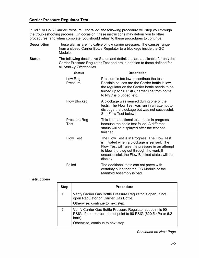
5-5
Carrier Pressure Regulator Test
If Col 1 or Col 2 Carrier Pressure Test failed, the following procedure will step you through the troubleshooting process. On occasion, these instructions may detour you to other procedures, and when complete, you should return to these procedures to continue.
Description These alarms are indicative of low carrier pressure. The causes range from a closed Carrier Bottle Regulator to a blockage inside the GC Module.
Status The following descriptive Status and definitions are applicable for only the Carrier Pressure Regulator Test and are in addition to those defined for all Start-up Diagnostics.
Status Description
Low Reg Pressure
Pressure is too low to continue the test. Possible causes are the Carrier bottle is low, the regulator on the Carrier bottle needs to be turned up to 90 PSIG, carrier line from bottle to NGC is plugged, etc.
Flow Blocked A blockage was sensed during one of the tests. The Flow Test was run in an attempt to dislodge the blockage but was not successful. See Flow Test below.·
Pressure Reg Test
This is an additional test that is in progress because the basic test failed. A different status will be displayed after the test has finished.
Flow Test The Flow Test is in Progress. The Flow Test is initiated when a blockage is sensed. The Flow Test will raise the pressure in an attempt to blow the plug out through the vent. If unsuccessful, the Flow Blocked status will be display
Failed The additional tests can not prove with certainty but either the GC Module or the Manifold Assembly is bad.
Instructions
Step Procedure
1. Verify Carrier Gas Bottle Pressure Regulator is open. If not, open Regulator on Carrier Gas Bottle. Otherwise, continue to next step.
2. Verify Carrier Gas Bottle Pressure Regulator set point is 90 PSIG. If not, correct the set point to 90 PSIG (620.5 kPa or 6.2 bars). Otherwise, continue to next step.
Continued on Next Page

5-6
Carrier Pressure Regulator Test, Cont.
Step Procedure, Cont.
3. Perform Column Vent Pressure Test Procedure in this Chapter for both Column Vent 1 and Column Vent 2. If either test failed, proceed to the next step.
4. Using the Replacing Analytical Processor Assembly instructions in Chapter 4 Maintenance, replace Analytical Processor.
Totalflow recommends that a replacement Analytical Module be installed at this point and additional steps be performed in a clean, lint free atmosphere. Because the customer does not have the required equipment to determine which specific module needs replaced, the final instructions are by process of elimination, beginning with the most likely module.
The Totalflow Repair Department offers a range of services for troubleshooting and repairing/replacing the non-functioning parts. For more information regarding the repair service, contact Customer Service:
USA: (800) 442-3097 or International: 001-918-338-4888
5. Using the Replacing Manifold Assembly instructions in Chapter 4 Maintenance, replace Manifold Assembly.
6. Using the Replacing GC Module instructions in Chapter 4 Maintenance, replace GC Module.
Oven Temperature Test
If the Oven Temperature Test failed, the following procedure will step you through the troubleshooting process. On occasion, these instructions may detour you to other procedures, and when complete, you should return to these procedures to continue.
Description This alarm is indicative of a temperature condition. The causes range from an unplugged cable to a bad module heater.
Instructions
Step Procedure
1. Using the Replacing Temperature Sensor to GC Module Cable instructions in Chapter 4 Maintenance, verify that cable is plugged in and in good repair. If cable is unplugged or appears to be damaged, replace or plug-in cable. Otherwise, continue to the next step.
Continued on Next Page

5-7
Oven Temperature Test, Cont.
Step Procedure, Cont.
2. Using the Replacing Analytical Processor to GC Module Cable instructions in Chapter 4 Maintenance, verify that cable is plugged in and in good repair. If cable is unplugged or appears to be damaged, replace or plug-in cable. Otherwise, continue to the next step.
3. Using the Replacing Analytical Processor Assembly instructions in Chapter 4 Maintenance, replace Analytical Processor.
Totalflow recommends that a replacement Analytical Module be installed at this point and additional steps be performed in a clean, lint free atmosphere.
The Totalflow Repair Department offers a range of services for troubleshooting and repairing/replacing the non-functioning parts. For more information regarding the repair service, contact Customer Service:
USA: (800) 442-3097 or International: 001-918-338-4888
4. Using the Replacing Manifold Assembly instructions in Chapter 4 Maintenance, replace Manifold Assembly.
Processor Control Test
If Col 1 or Col 2 Carrier Pressure Test failed, or the Oven Temperature test failed, the following procedure will step you through the troubleshooting process. On occasion, these instructions may detour you to other procedures, and when complete, you should return to these procedures to continue.
Description These alarms are indicative of a lack of ability to control a function. If the Failure is either one or both of the Column Carrier Pressure tests, it could be a missing or failed gasket. If the Failure is in the Oven Control temperature test, it could be something as easy as a missing GC Module Cover or Analytical Module Thermal Flask.
Instructions
Step Procedure
1. If the Start-up Diagnostics are being performed following disassembly/replacement of a module or spare part, insure that unit is completely reassembled, including the Thermal flask and both the front and rear end caps and re-start the Diagnostics. If Diagnostics again fail, repeat disassembly steps and verify that all gaskets and connections are tight and correctly installed. Otherwise continue to the next step.
Continued on Next Page

5-8
Processor Control Test, Cont.
Instructions
Step Procedure, Cont.
2. If the Start-up Diagnostics are being performed from an initial startup, verify that Analytical Module is not loose inside the enclosure.
3. Verify that the GC Module is tight and that cables are correctly installed and not damaged.
4. Reassemble unit and restart Diagnostics. If unit continues to fail, replace entire analytical Module and return to Totalflow for Warranty Repair/Replacement.
Stream Test
The Stream Flow Diagnostics go through a series of tests, testing the stream pressure at different conditions as listed below. Each column will display the pressure results after that part of the test has completed. The Status column will reflect the current and final status of the tests. The following procedure will step you through the troubleshooting process. On occasion, these instructions may detour you to other procedures, and when complete, you should return to these procedures to continue.
During the Stream Test, streams with no gas pressure will Fail and they will be disabled in the Stream Sequence. To enable these Streams, please click on the Stream Setup button on the Analyzer Operation screen.
Status The following descriptive Status and definitions are applicable for only the Stream Test and are in addition to those defined for all Start-up Diagnostics.
Status Description Failed Initial Pressure Failed the Initial Pressure test. Failed Resting Pressure
Failed the Resting Pressure test.
Failed No Pressure Failed the Maximum Pressure test. Failed Holding Pressure
Failed the Holding Pressure test.
Failed Flowing Pressure
Failed the Flowing Pressure test.
Failed Ending Pressure Failed the Ending Pressure test. Waiting This will be displayed by streams waiting to
be tested. The tests are run sequentially.
Continued on Next Page

5-9
Stream Test, Cont.
Description These alarms are indicative of a sample pressure problem. The causes range from a plugged Frit Filter to a bad GC Module.
Instructions
Step Procedure
1. Perform Sample Vent Pressure Test procedure, found in this Chapter, for Sample Vent. If test failed, proceed to the next step.
2. Perform Feed-Through Assembly Blockage Test on Sample Vent (SV). If test fails, replace Feed-Through Assembly with new or refurbished assembly. Otherwise, continue to next step.
Totalflow recommends that a replacement Analytical Module be installed at this point and additional steps be performed in a clean, lint free atmosphere. Because the customer does not have the required equipment to determine which specific module needs replaced, the final instructions are by process of elimination, beginning with the most likely module.
The Totalflow Repair Department offers a range of services for troubleshooting and repairing/replacing the non-functioning parts. For more information regarding the repair service, contact Customer Service:
USA: (800) 442-3097 or International: 001-918-338-4888
3. Using the Replacing Manifold Assembly instructions in Chapter 4 Maintenance, replace Manifold Assembly.
4. Using the Replacing GC Module instructions in Chapter 4 Maintenance, replace GC Module.

5-10
Troubleshooting Alarms
Overview
This section focuses on determining what has caused an alarm following normal operation. The Totalflow® NGC8200 has an extensive built-in list of alarms, some of which are user configurable. These alarms may be grouped into three areas: Warning, Fault and System Fault. See Table 5-1 for a list of all enabled alarms. To view all the available alarms, select Setup under Stream 1 on the Analyzer Operation screen and select Alarm Definitions.
Additionally, component High/Low Concentration, Component Peak not Found, Component RF Limit Exceeded alarms are available but disabled. These alarms may be enabled by the user, but are not included here for purposes of troubleshooting. Please see the PCCU32 Help Files for more information regarding these.
Table 5-1 NGC8200 Alarms
Description Enable Type Severity Pressure Regulator 1 Yes GT Fault Pressure Regulator 2 Yes GT Fault Sample Pressure Yes GT Fault Oven Temperature Error Yes GT System Fault No Stream Valve Selected Yes GT System Fault Digital-Analog Bd Comm Error Yes GT System Fault Calculation Error Yes GT Fault Calibration Un-Normalized Total Yes GT Fault Stream Sequence Error Yes GT Fault Calibration CV Percent Error Yes GT Fault RF Pct Error Yes GT Fault Analog Bd Ambient Temp Yes GT Warning Analog Power Supply Yes GT Warning Low Carrier Gas Bottle (DI1) Yes LT Warning Low Cal Gas Bottle (DI2) Yes LT Warning GCM Chrom Process Yes GT System Fault Bad Bead Yes GT Fault No Pilot Valve Change Detected Yes GT Fault Sample Flow Detect Yes GT Fault CPU Loading Yes GT Warning System Memory Available Yes LT Warning Ram File Available Yes LT Warning Flash File Available Yes LT Warning Missing Peak-Cal Not Used Yes GT Warning Stream Un-Normalized Total Yes GT Warning
Continued on Next Page
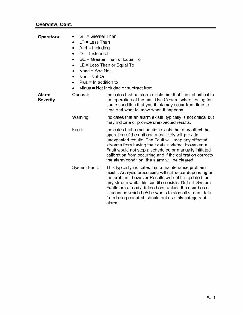
5-11
Overview, Cont.
Operators • GT = Greater Than • LT = Less Than • And = Including • Or = Instead of • GE = Greater Than or Equal To • LE = Less Than or Equal To • Nand = And Not • Nor = Not Or • Plus = In addition to • Minus = Not Included or subtract from
Alarm Severity
General: Indicates that an alarm exists, but that it is not critical to the operation of the unit. Use General when testing for some condition that you think may occur from time to time and want to know when it happens.
Warning: Indicates that an alarm exists, typically is not critical but may indicate or provide unexpected results.
Fault: Indicates that a malfunction exists that may affect the operation of the unit and most likely will provide unexpected results. The Fault will keep any affected streams from having their data updated. However, a Fault would not stop a scheduled or manually initiated calibration from occurring and if the calibration corrects the alarm condition, the alarm will be cleared.
System Fault: This typically indicates that a maintenance problem exists. Analysis processing will still occur depending on the problem, however Results will not be updated for any stream while this condition exists. Default System Faults are already defined and unless the user has a situation in which he/she wants to stop all stream data from being updated, should not use this category of alarm.
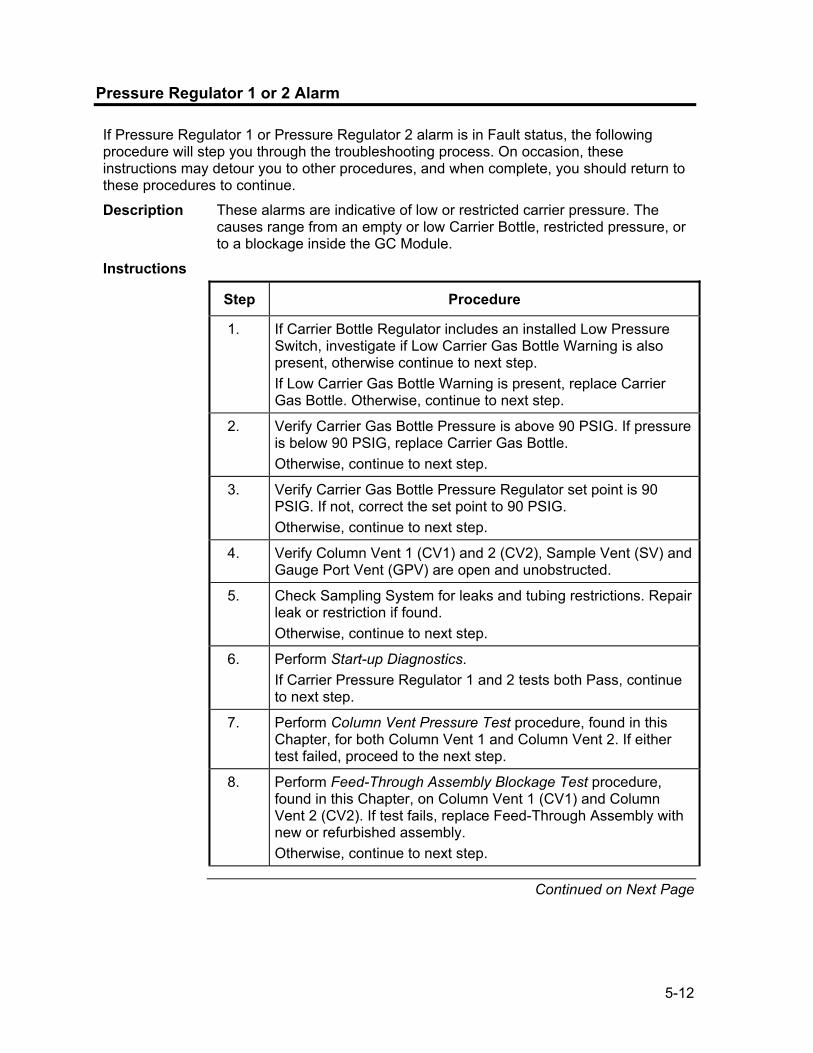
5-12
Pressure Regulator 1 or 2 Alarm
If Pressure Regulator 1 or Pressure Regulator 2 alarm is in Fault status, the following procedure will step you through the troubleshooting process. On occasion, these instructions may detour you to other procedures, and when complete, you should return to these procedures to continue.
Description These alarms are indicative of low or restricted carrier pressure. The causes range from an empty or low Carrier Bottle, restricted pressure, or to a blockage inside the GC Module.
Instructions
Step Procedure
1. If Carrier Bottle Regulator includes an installed Low Pressure Switch, investigate if Low Carrier Gas Bottle Warning is also present, otherwise continue to next step. If Low Carrier Gas Bottle Warning is present, replace Carrier Gas Bottle. Otherwise, continue to next step.
2. Verify Carrier Gas Bottle Pressure is above 90 PSIG. If pressure is below 90 PSIG, replace Carrier Gas Bottle. Otherwise, continue to next step.
3. Verify Carrier Gas Bottle Pressure Regulator set point is 90 PSIG. If not, correct the set point to 90 PSIG. Otherwise, continue to next step.
4. Verify Column Vent 1 (CV1) and 2 (CV2), Sample Vent (SV) and Gauge Port Vent (GPV) are open and unobstructed.
5. Check Sampling System for leaks and tubing restrictions. Repair leak or restriction if found. Otherwise, continue to next step.
6. Perform Start-up Diagnostics. If Carrier Pressure Regulator 1 and 2 tests both Pass, continue to next step.
7. Perform Column Vent Pressure Test procedure, found in this Chapter, for both Column Vent 1 and Column Vent 2. If either test failed, proceed to the next step.
8. Perform Feed-Through Assembly Blockage Test procedure, found in this Chapter, on Column Vent 1 (CV1) and Column Vent 2 (CV2). If test fails, replace Feed-Through Assembly with new or refurbished assembly. Otherwise, continue to next step.
Continued on Next Page

5-13
Pressure Regulator 1 or 2 Alarm, Cont.
Step Procedure, Cont.
Totalflow recommends that a replacement Analytical Module be installed at this point and additional steps be performed in a clean, lint free atmosphere.
Because the customer does not have the required equipment to determine which specific module needs replaced, the final instructions are by process of elimination, beginning with the most likely module.
The Totalflow Repair Department offers a range of services for troubleshooting and repairing/replacing the non-functioning parts. For more information regarding the repair service, contact Customer Service:
USA: (800) 442-3097 or International: 001-918-338-4888
9. Using the Replacing Analytical Module instructions in Chapter 4 Maintenance, replace Analytical Module Assembly.
10. Using the Replacing Manifold Assembly instructions in Chapter 4 Maintenance, replace Manifold Assembly.
11. Using the Replacing GC Module instructions in Chapter 4 Maintenance, replace GC Module.
Sample Pressure Alarm
If Sample Pressure alarm is in Fault status, the following procedure will step you through the troubleshooting process. On occasion, these instructions may detour you to other procedures, and when complete, you should return to these procedures to continue.
Description These alarms are indicative of low sample or calibration gas pressure. The causes range from an empty or low Calibration Gas Bottle to a blockage inside the GC Module.
Instructions
Step Procedure
1. If Calibration Gas Bottle Regulator includes an installed Low Pressure Switch, investigate if Lo Bottle Calibration Gas Warning is also present, otherwise continue to next step. If Lo Bottle Calibration Gas Warning is present, replace Calibration Gas Bottle. Otherwise, continue to next step.
2. Verify Calibration Gas Bottle Pressure is above 15 PSIG. If pressure is below 15 PSIG, replace Calibration Gas Bottle. Otherwise, continue to next step.
Continued on Next Page

5-14
Sample Pressure Alarm, Cont.
Step Procedure, Cont.
3. Verify Calibration Gas Bottle Pressure Regulator set point is 15 PSIG. If not, correct the set point to 15 PSIG. Otherwise, continue to next step.
4. Verify Sample Vent is open and unobstructed.
5. Perform Sample Vent Pressure Test found in this chapter. If test failed, continue to the next step. Otherwise, skip to step 7.
6. Perform Feed-Through Assembly Blockage Test found in this Chapter, on Sample Vent (SV). If test fails, replace Feed-Through Assembly. Otherwise, continue to next step.
7. Check Sampling System for leaks and tubing restrictions. Repair leak or restriction if found. Otherwise, continue to next step.
8. Perform Start-up Diagnostics. If Stream Test fails, continue to next step.
9. Follow Replacing Frit Filters instructions in Chapter 4, Maintenance, verify filters are clean and free of obstructions. If needed, replace Filters.
Totalflow recommends that a replacement Analytical Module be installed at this point and additional steps be performed in a clean, lint free atmosphere.
Because the customer does not have the required equipment to determine which specific module needs replaced, the final instructions are by process of elimination, beginning with the most likely module.
The Totalflow Repair Department offers a range of services for troubleshooting and repairing/replacing the non-functioning parts. For more information regarding the repair service, contact Customer Service:
USA: (800) 442-3097 or International: 001-918-338-4888
10. Using the Replacing Analytical Module instructions in Chapter 4 Maintenance, replace Analytical Module Assembly.
11. Using the Replacing Manifold Assembly instructions in Chapter 4 Maintenance, replace Manifold Assembly.
12. Using the Replacing GC Module instructions in Chapter 4 Maintenance, replace GC Module.
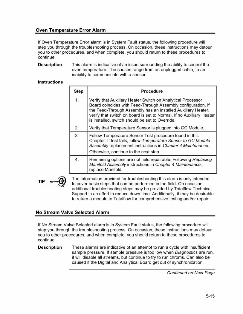
5-15
Oven Temperature Error Alarm
If Oven Temperature Error alarm is in System Fault status, the following procedure will step you through the troubleshooting process. On occasion, these instructions may detour you to other procedures, and when complete, you should return to these procedures to continue.
Description This alarm is indicative of an issue surrounding the ability to control the oven temperature. The causes range from an unplugged cable, to an inability to communicate with a sensor.
Instructions
Step Procedure
1. Verify that Auxiliary Heater Switch on Analytical Processor Board coincides with Feed-Through Assembly configuration. If the Feed-Through Assembly has an installed Auxiliary Heater, verify that switch on board is set to Normal. If no Auxiliary Heater is installed, switch should be set to Override.
2. Verify that Temperature Sensor is plugged into GC Module.
3. Follow Temperature Sensor Test procedure found in this Chapter. If test fails, follow Temperature Sensor to GC Module Assembly replacement instructions in Chapter 4 Maintenance. Otherwise, continue to the next step.
4. Remaining options are not field repairable. Following Replacing Manifold Assembly instructions in Chapter 4 Maintenance, replace Manifold.
The information provided for troubleshooting this alarm is only intended to cover basic steps that can be performed in the field. On occasion, additional troubleshooting steps may be provided by Totalflow Technical Support in an effort to reduce down time. Additionally, it may be desirable to return a module to Totalflow for comprehensive testing and/or repair.
No Stream Valve Selected Alarm
If No Stream Valve Selected alarm is in System Fault status, the following procedure will step you through the troubleshooting process. On occasion, these instructions may detour you to other procedures, and when complete, you should return to these procedures to continue.
Description These alarms are indicative of an attempt to run a cycle with insufficient sample pressure. If sample pressure is too low when Diagnostics are run, it will disable all streams, but continue to try to run chroms. Can also be caused if the Digital and Analytical Board get out of synchronization.
Continued on Next Page

5-16
No Stream Valve Selected Alarm, Cont.
Instructions
Step Procedure
1. Check Sampling System for leaks, tubing restrictions and incorrect pressure setting. Repair leak or restriction, or adjust pressure setting if found. Otherwise, continue to next step.
2. Place NGC in Hold, allow ten minutes (approximately 2 cycles) to lapse, and then run a single cycle. If alarm reappears, continue to the next step.
3. Unit should still be in Hold. Manually enable all streams.
4. Perform Start-up Diagnostics. If Stream Test fails, continue to next step.
5. Perform Warm Start.
The information provided for troubleshooting this alarm is only intended to cover basic steps that can be performed in the field. On occasion, additional troubleshooting steps may be provided by Totalflow Technical Support in an effort to reduce down time. Additionally, it may be desirable to return a module to Totalflow for comprehensive testing and/or repair.
Digital-Analog Board Communication Error Alarm
If Digital-Analog Board Communication Error alarm is in System Fault status, the following procedure will step you through the troubleshooting process. On occasion, these instructions may detour you to other procedures, and when complete, you should return to these procedures to continue. Description These alarms are indicative of a communication error between the Digital
Board and the Analytical Processor Board. Verify cable connectors are firmly and correctly connected to both the Digital and Analytical Processor boards.
Instructions
Step Procedure
1. In the Alarm Log, check frequency of error. If multiple errors exist, place unit in Hold and then launch a cycle.
2. If alarms continue to register, perform a Warm Start.
3. When unit completes the Start-up Diagnostics without error, place unit in Run.
Continued on Next Page

5-17
Digital-Analog Board Communication Error Alarm, Cont.
Step Procedure, Cont.
4. Following 2-3 cycles, verify that no new alarms are registering. If alarms continue to register, call Totalflow Technical Support.
The information provided for troubleshooting this alarm is only intended to cover basic steps that can be performed in the field. On occasion, additional troubleshooting steps may be provided by Totalflow Technical Support in an effort to reduce down time. Additionally, it may be desirable to return a module to Totalflow for comprehensive testing and/or repair.
Calculation Error Alarm
If Calculation Error alarm is in Fault status, the following procedure will step you through the troubleshooting process. On occasion, these instructions may detour you to other procedures, and when complete, you should return to these procedures to continue.
Description These alarms are indicative of AGA-8 Compressibility calculation not functioning properly. Typically this error would be caused by a gas sample being out of specification for AGA-8, but could indicate that the component’s peak has shifted.
Instructions
Step Procedure
1. Following Calibrating the NGC instructions in Chapter 3 Startup, perform a calibration ensuring that the Next Mode is set to Hold.
2. When unit enters Hold, select Peak Find.
3. Verify that peaks are correctly labeled and integrated. If peaks are not correctly labeled and integrated, continue to the next step.Otherwise, skip to step 5.
4. In the Peak Find screen, Run Auto PF. This process will typically require 45 minutes to complete. When cycle is complete, repeat Step 3.
5. Under Next Mode, select Run.
6. Allow unit to run a minimum of an hour, then perform a calibration.
The information provided for troubleshooting this alarm is only intended to cover basic steps that can be performed in the field. On occasion, additional troubleshooting steps may be provided by Totalflow Technical Support in an effort to reduce down time. Additionally, it may be desirable to return a module to Totalflow for comprehensive testing and/or repair.

5-18
Calibration Un-Normalized Error Alarm
If Calibration Un-Normalized Error Alarm is in Fault status, the following procedure will step you through the troubleshooting process. On occasion, these instructions may detour you to other procedures, and when complete, you should return to these procedures to continue.
Description These alarms are indicative of a change to the Un-Normalized Total of sufficient percentage to activate the alarm. This alarm will discontinue a scheduled calibration and will need to be disabled prior to calibrating the unit.
Instructions
Step Procedure
1. On the Analyzer Operation screen, click Hold under Next Mode. When unit completes the current cycle and enters Hold, you may continue to the next step.
2. Verify Calibration Blend concentrations to Calibration Blend concentrations listed on the Calibration Setup screen. If errors exist, make corrections and Send the setup when complete.
3. Under Stream Setup, Alarm Definitions, locate the Calibration Un-Normalized Error Alarm and set Alarm Enable to No. Send change. Repeat for any additional streams with this alarm.
4. Follow Calibrating the NGC instructions in Chapter 3 Startup, perform a calibration ensuring that the Next Mode is set to Hold.
5. When unit enters Hold, select Peak Find.
6. Verify that peaks are correctly labeled and integrated. If peaks are correctly labeled and integrated, return unit to operation, otherwise continue to the next step.
7. Select Peak Find from the Analyzer Operation screen. Ensure that Automatic is check marked, then select Run Auto PF. This procedure will require approximately 45 minutes.
8. When unit enters Hold, verify that peaks are correctly labeled and integrated. If peaks are correctly labeled and integrated, return unit to operation, otherwise contact Totalflow Technical Support.
9. Reset the Alarm Enable to Yes. Verify that Alarm Threshold is a valid configuration. Typically, the UnNormalized Total should be within ±.50% (between 99.5 and 100.5).
10. Return unit to regular operation.
The information provided for troubleshooting this alarm is only intended to cover basic steps that can be performed in the field. On occasion, additional troubleshooting steps may be provided by Totalflow Technical Support in an effort to reduce down time. Additionally, it may be desirable to return a module to Totalflow for comprehensive testing and/or repair.

5-19
Stream Sequence Error Alarm
If Stream Sequence Error alarm is in Fault status, the following procedure will step you through the troubleshooting process. On occasion, these instructions may detour you to other procedures, and when complete, you should return to these procedures to continue.
Description These alarms are indicative of a synchronization problem following a manual Data Post Process in Factory Mode.
Instructions
Step Procedure
1. On the Analyzer Operation screen, click Hold under Next Mode. When unit completes the current cycle and enters Hold, you may continue to the next step.
2. Following Reset Procedure instructions in Chapter 4 Maintenance, perform a Warm Start.
Calibration CV Percent Error Alarm
If Calibration CV Percent Error alarm is in Fault status, the following procedure will step you through the troubleshooting process. On occasion, these instructions may detour you to other procedures, and when complete, you should return to these procedures to continue.
Description These alarms are indicative of a change to the CV Percent of sufficient percentage to activate the alarm. This alarm will discontinue a scheduled calibration and will need to be disabled prior to calibrating the unit.
Instructions
Step Procedure
1. On the Analyzer Operation screen, click Hold under Next Mode. When unit completes the current cycle and enters Hold, you may continue to the next step.
2. Verify Calibration Blend concentrations to Calibration Blend concentrations listed on the Calibration Setup screen. If errors exist, make corrections and Send the setup when complete.
3. Under Stream Setup, Alarm Definitions, locate the Calibration CV Percent Error Alarm and set Alarm Enable to No. Send change. Repeat for any additional streams with this alarm.
4. Following Calibrating the NGC instructions in Chapter 3 Startup, perform a calibration ensuring that the Next Mode is set to Hold.
5. When unit enters Hold, select Peak Find.
Continued on Next Page

5-20
Calibration CV Percent Error Alarm, Cont.
Step Procedure, Cont.
6. Verify that peaks are correctly labeled and integrated. If peaks are correctly labeled and integrated, return unit to operation.
7. Reset the Alarm Enable to Yes. Verify that Alarm Threshold is a valid configuration.
8. Return unit to regular operation.
The information provided for troubleshooting this alarm is only intended to cover basic steps that can be performed in the field. On occasion, additional troubleshooting steps may be provided by Totalflow Technical Support in an effort to reduce down time. Additionally, it may be desirable to return a module to Totalflow for comprehensive testing and/or repair.
Calibration RF Percent Error Alarm
If Response Factor (RF) Percent Error alarm is in Fault status, the following procedure will step you through the troubleshooting process. On occasion, these instructions may detour you to other procedures, and when complete, you should return to these procedures to continue.
Description These alarms are indicative of a change to the Response Factor of sufficient percentage to activate the alarm. This alarm will discontinue a scheduled calibration and will need to be disabled prior to calibrating the unit.
Instructions
Step Procedure
1. Verify Calibration Blend concentrations to Calibration Blend concentrations listed on the Calibration Setup screen. If errors exist, make corrections and Send the setup when complete.
2. On the Analyzer Operation screen, click Hold under Next Mode. When unit completes the current cycle and enters Hold, you may continue to the next step.
3. Under Stream Setup, Alarm Definitions, locate the RF Percent Error Alarm and set Alarm Enable to No. Send change. Repeat for any additional streams with this alarm.
4. When unit enters Hold, select Peak Find. Select Run Auto PF.
5. Verify that peaks are correctly labeled and integrated. If peaks are correctly labeled and integrated, return unit to operation.
Continued on Next Page

5-21
Calibration RF Percent Error Alarm, Cont.
Step Procedure, Cont.
6. Allow unit to cycle 3-4 times.
7. Following Calibrating the NGC instructions in Chapter 3 Startup, perform a calibration ensuring that the Next Mode is set to Hold.
8. Reset the Alarm Enable to Yes. Verify that Alarm Threshold is a valid configuration.
9. Return unit to regular operation.
The information provided for troubleshooting this alarm is only intended to cover basic steps that can be performed in the field. On occasion, additional troubleshooting steps may be provided by Totalflow Technical Support in an effort to reduce down time. Additionally, it may be desirable to return a module to Totalflow for comprehensive testing and/or repair.
Enclosure Temperature Alarm
If Enclosure Temperature alarm is in Warning status, the following procedure will step you through the troubleshooting process. On occasion, these instructions may detour you to other procedures, and when complete, you should return to these procedures to continue. Description These alarms are indicative of either extremely high or low temperatures
inside the enclosure. Causes could range from external temperatures being extremely high or low, to a bad Temperature Sensor on the Analytical Board.
Instructions
Step Procedure
1. Compare outside temperature with the temperature reading on the Analyzer Operation screen Enclosure Temperature. Atmospheric temperature could be less than the Enclosure Temperature by as much as 20 degrees. If the temperature differential seems reasonable, the unit may be operating out of range. This unit is designed to operate between 0 F and 120 F. Otherwise, continue to the next step.
2. If the temperature differential does not seem reasonable, the Analytical Processor Assembly may have a bad temperature sensor. As this alarm is only a warning, it will not effect the operation of the unit. You may replace the Analytical Processor Assembly at your leisure.
The Totalflow Repair Department offers a range of services for troubleshooting and repairing/replacing the non-functioning parts. For more information regarding the repair service, contact Customer Service:
USA: (800) 442-3097 or International: 001-918-338-4888

5-22
Power Supply Alarm
If Power Supply alarm is in Warning status, the following procedure will step you through the troubleshooting process. On occasion, these instructions may detour you to other procedures, and when complete, you should return to these procedures to continue.
Description These alarms are indicative of input voltage either below 11 volts or above 16 volts. Causes may range from a Power Supply issue to a bad cable.
Instructions
Step Procedure
1. Check power supply to Termination Panel, following instructions later in this chapter, Termination Panel Supply Voltage Test. If test fails, restore power supply to proper working specifications. Otherwise, continue to the next step.
2. Following cable replacement instructions in Chapter 4 Maintenance, check Analytical Processor to Termination Panel Cable for damage. If cable is damaged, replace. Otherwise, continue to the next step.
3. Following cable replacement instructions in Chapter 4 Maintenance, check Termination Panel to Digital Controller Cable for damage. If cable is damaged, replace. Otherwise, contact Totalflow Technical Support for additional instructions.
Low Carrier Gas Bottle (DI1) Alarm
If Low Carrier Gas Bottle (DI1) alarm is in Warning status, the following procedure will step you through the troubleshooting process. On occasion, these instructions may detour you to other procedures, and when complete, you should return to these procedures to continue. Description These alarms are indicative of Carrier Gas Bottle pressure below the
threshold.
Instructions
Step Procedure
1. Verify that the Carrier Gas Bottle Regulator Low Pressure Switch threshold is set around 90 PSIG. Alarm is switched when pressure drops below threshold.
2. If threshold is above current bottle PSIG, replace Carrier Gas Bottle.
3. If threshold is below current bottle PSIG, verify Regulator is functioning properly.
4. Perform Abnormal Calibration Gas Depletion procedure, found in this Chapter. If procedure fails to locate the problem, contact Totalflow Technical Support following procedure in the Introduction section of this manual.

5-23
Low Cal Gas Bottle (DI2) Alarm
If Lo Bottle Calibration Gas (DI2) alarm is in Warning status, the following procedure will step you through the troubleshooting process. On occasion, these instructions may detour you to other procedures, and when complete, you should return to these procedures to continue.
Description These alarms are indicative of Calibration Gas Bottle pressure below the threshold.
Instructions
Step Procedure
1. Verify that the Calibration Gas Bottle Regulator Low Pressure Switch threshold is set around 15 PSIG. Alarm is switched when pressure drops below threshold.
2. If threshold is above current bottle PSIG, replace Calibration Gas Bottle.
3. If threshold is below current bottle PSIG, verify Regulator is functioning properly.
4. Perform Abnormal Calibration Gas Depletion procedure, found in this Chapter. If procedure fails to locate the problem, contact Totalflow Technical Support following procedure in the Introduction section of this manual.
GCM Processing Error Alarm
If GCM Chrom Process alarm is in Warning status, the following procedure will step you through the troubleshooting process. On occasion, these instructions may detour you to other procedures, and when complete, you should return to these procedures to continue.
Description This alarm is indicative of an error that stops the GCM Application from signaling the Chrom Application to process a chrom. The following internal errors could instigate this alarm: Communication Response Error, Polling Error, Sequence Error, Data Error.
Instructions
Step Procedure
1. In the Alarm Log, check frequency of error. If multiple errors exist, place unit in Hold and then launch a cycle.
2. If alarms continue to register, perform a Warm Start.
3. When unit completes the Start-up Diagnostics without error, place unit in Run.
4. Following 2-3 cycles, verify that no new alarms are registering. If alarms continue to register, call Totalflow Technical Support.

5-24
Bad Bead Alarm
If Bad Bead alarm is in Fault status, the following procedure will step you through the troubleshooting process. On occasion, these instructions may detour you to other procedures, and when complete, you should return to these procedures to continue.
Description These alarms are indicative of problem with the GC Module.
Instructions
Step Procedure
1. Following GC Module Replacement Instructions in Chapter 4 Maintenance, replace GC Module.
No Pilot Valve Change Detected Alarm
If No Pilot Valve Change Detected alarm is in Warning status, the following procedure will step you through the troubleshooting process. On occasion, these instructions may detour you to other procedures, and when complete, you should return to these procedures to continue.
Description These alarms are indicative of pressure regulator problem on the Manifold. During Backflush, a Valve is changed, but no disturbance is registered.
Instructions
Step Procedure
1. Verify Carrier Gas Bottle Pressure is above 90 PSIG. If pressure is below 90 PSIG, replace Carrier Gas Bottle. Otherwise, continue to next step.
2. Verify Carrier Gas Bottle Pressure Regulator set point is 90 PSIG. If not, correct the set point to 90 PSIG. Otherwise, continue to next step.
3. Following Manifold Replacement instructions in Chapter 4 Maintenance, replace Manifold.
Sample Flow Detection Alarm
If Sample Flow Detection alarm is in Fault status, the following procedure will step you through the troubleshooting process. On occasion, these instructions may detour you to other procedures, and when complete, you should return to these procedures to continue.
Description These alarms are indicative of pressure issue. Blocked vent tube, too short bleed cycle, Stream Test is in Auto.
Continued on Next Page

5-25
Sample Flow Detection Alarm, Cont.
Instructions
Step Procedure
1. Inspect vent tubes for blockage including crimps in tubing, dirt or debris.
2. Following instructions later in this chapter, perform Sample Pressure Test.
3. Verify Sample Bleed Time is set greater than 1 Second.
4. Following GC Module Replacement instructions in Chapter 4 Maintenance, replace GC Module.
CPU Loading Alarm
If CPU Loading alarm is in Warning status, the following procedure will step you through the troubleshooting process. On occasion, these instructions may detour you to other procedures, and when complete, you should return to these procedures to continue.
Description These alarms are indicative of processor being overloaded. An occasional spike in processor loading is to be expected. Multiple occurrences are not field repairable.
Instructions
Step Procedure
1. View alarm history for multiple occurrences. If an occasional warning is registered, this is not a problem.
2. If multiple alarm occurrences exist contact Totalflow Technical Support for additional help.
System Memory Available Alarm
If System Memory Available alarm is in Warning status, the following procedure will step you through the troubleshooting process. On occasion, these instructions may detour you to other procedures, and when complete, you should return to these procedures to continue.
Description These alarms are indicative of the Task Memory resource getting full. Recommended files size for Task Memory is 1 to 2 MB. This alarm may be received after adding additional applications.
Continued on Next Page

5-26
System Memory Available Alarm, Cont.
Instructions
Step Procedure
1. View alarm history for multiple occurrences. If an occasional warning is registered, this is not a problem.
2. View Resources from PCCU Entry screen to check available memory. If applicable, the Available Memory could be increased incrementally.
Please note that when increasing the Available Memory, the Available RAM File Space is reduced. Caution should be used!
3. Following Reset Procedure instructions in Chapter 4 Maintenance, Warm Start the unit to defrag the System Memory.
4. Reducing the number of instantiated applications may be required. Contact Totalflow Technical Support for assistance.
RAM File Available Alarm
If RAM File Available alarm is in Warning status, the following procedure will step you through the troubleshooting process. On occasion, these instructions may detour you to other procedures, and when complete, you should return to these procedures to continue.
Description These alarms are indicative of the TFData File resource getting full. Recommended files size for TFData is 2 to 3 MB. This alarm may be received after changing Log Period frequency, adding Applications or setting up additional Trend Files.
Instructions
Step Procedure
1. View alarm history for multiple occurrences. If an occasional warning is registered, this is not a problem.
2. View Resources from PCCU Entry screen to check available RAM File Space. If applicable, the RAM File Space could be increased incrementally.
Please note that when increasing the RAM File Space, the Available Memory File Space is reduced. Caution should be used!
3. Following Reset Procedure instructions in Chapter 4 Maintenance, Warm Start the unit to defrag the System Memory.
4. Reducing the number if instantiated applications, Trend Files or lengthening the Log Periods may be required. Contact Totalflow Technical Support for assistance.

5-27
FLASH File Available Alarm
If FLASH File Available alarm is in Warning status, the following procedure will step you through the troubleshooting process. On occasion, these instructions may detour you to other procedures, and when complete, you should return to these procedures to continue.
Description These alarms are indicative of a shortage of files space in the 32 MB FLASH. Typically this space is not user accessible, however instantiating too many applications may cause an alarm.
Instructions
Step Procedure
1. View alarm history for multiple occurrences. If an occasional warning is registered, this is not a problem.
2. Please contact Totalflow Technical Support for assistance.
Missing Peak-Calibration Not Used
If Missing Peak-Calibration Not Used is in Warning status, the following procedure will step you through the troubleshooting process. On occasion, these instructions may detour you to other procedures, and when complete, you should return to these procedures to continue.
Description These alarms are indicative of a missing peak during a calibration cycle and calibration will not be used.
Instructions
Step Procedure
1. Verify Calibration Blend concentrations to Calibration Blend concentrations listed on the Calibration Setup screen. If errors exist, make corrections and Send the setup when complete.
2. On the Analyzer Operation screen, click Hold under Next Mode. When unit completes the current cycle and enters Hold, you may continue to the next step.
3. When unit enters Hold, select Peak Find from the Analyzer Operation screen. Ensure that Automatic is check marked, then select Run Auto PF. This procedure will require approximately 45 minutes.
4. Verify that peaks are correctly labeled and integrated. Refer to Figure 3—5 and Figure 3—6 for comparison. On Chrom 1, NC5 Peak should elute around 160 seconds. On Chrom 2, C2 Peak should elute at approximately 220 seconds. If peaks are correctly labeled and integrated, return unit to operation, and continue to the next step, otherwise contact Totalflow Technical Support
Continued on Next Page

5-28
Missing Peak-Calibration Not Used, Cont.
Step Procedure, Cont.
5. Allow unit to cycle 3-4 times.
6. Follow Calibrating the NGC instructions in Chapter 3 Startup, perform a calibration ensuring that the Next Mode is set to Hold.
7. When unit enters Hold, verify that peaks are correctly labeled and integrated. If peaks are correctly labeled and integrated, return unit to operation.
8. If peaks are not correctly labeled and integrated, contact Totalflow Technical Support for assistance.
Stream Un-Normalized Total
If Stream Un-Normalized Total is in Warning status (default), the following procedure will step you through the troubleshooting process. If the severity of the alarm is set to Fault, the new stream data is not allowed to update. On occasion, these instructions may detour you to other procedures, and when complete, you should return to these procedures to continue.
Description These alarms are indicative of a change to the Process Stream Un-Normalized Total of sufficient percentage to activate the alarm.
Instructions
Step Procedure
1. Verify that Alarm Threshold is a valid configuration. Typically, the UnNormalized Total should be within ±.50% (between 99.5 and 100.5).
2. Verify Calibration Blend concentrations to Calibration Blend concentrations listed on the Calibration Setup screen. If errors exist, make corrections and Send the setup when complete.
3. On the Analyzer Operation screen, click Hold under Next Mode. When unit completes the current cycle and enters Hold, you may continue to the next step.
4. When unit enters Hold, select Peak Find. Select Run Auto PF. Ensure that Automatic is check marked, then select Run Auto PF. This procedure will require approximately 45 minutes.
5. Verify that peaks are correctly labeled and integrated. If peaks are correctly labeled and integrated, return unit to operation, otherwise continue to the next step.
6. Allow unit to cycle 3-4 times.
7. Follow Calibrating the NGC instructions in Chapter 3 Startup, perform a calibration.

5-29
Alarm Troubleshooting Tests
Sample Vent Pressure Test
Instructions
Step Procedure
1. Attach Flowmeter to SV.
2. From the Analyzer Operation screen, click on Diagnostics.
3. Select the Manual Operation tab.
4. Under Manual Control, Open Sample Shutoff Valve.
5. When opened, SV should measure a spike to 15 sccm. Close Valve when done reading.
6. If SV does not spike to 15 sccm, the test has failed.
7. Return to troubleshooting instructions.
Column Vent Pressure Test
Instructions
Step Procedure
1. Attach Flowmeter to CV1.
2. From the Analyzer Operation screen, click on Diagnostics.
3. Select the Manual Operation tab.
4. Under Manual Control, Open Stream 1 Valve.
5. When opened, CV1 should measure between 3–12 sccm. Close Valve when done reading.
6. If CV1 measures within range, continue to the next step. If CV1 does not measure within range, the test has failed. Return to troubleshooting alarm instructions.
7. Attach Flowmeter to CV2.
8. Open Stream 1 Valve.
9. When opened, CV2 should measure between 3–12 sccm. Close Valve when done reading.
10. If CV2 does not measure within range, test has failed. Return to troubleshooting alarm instructions.

5-30
Sample Pressure Test
Instructions
Step Procedure
1. Place unit in Hold.
2. From the Analyzer Operation screen, click on Diagnostics.
3. Select the Manual Operation tab and select Monitor.
4. Read Sample Pressure from Current reading.
5. Under Manual Control, open Stream 1 Valve or stream reflecting alarm.
6. Under Manual Control, close Sample Shutoff Valve.
7. Sample Pressure reading under Current should increase.
8. Under Manual Control, open Sample Shutoff Valve.
9. Sample Pressure reading under Current should decrease rapidly.
10. If pressure decreases slowly, close Sample Shutoff Valve and return to troubleshooting alarm instructions, test has failed.
Feed-Through Assembly Blockage Test
Instructions
Step Procedure
1. Remove Feed-Through Assembly from NGC following Feed-Through Assembly instructions in Chapter 4 Maintenance.
2. If testing from the Pressure Regulator 1 or 2 Alarm, continue to Steps 3 and 4. If testing from Stream Test in the Start-up Diagnostics or from the Sample Pressure Alarm, skip to Step 5.
3. Attach pressure source to CV1 and activate. If flow through assembly is impeded, the test has failed. Return to troubleshooting alarm instructions. Otherwise, continue to next step.
4. Attach pressure source to CV2 and activate. If flow through assembly is impeded, the test has failed. Return to Column Vent Pressure Test.
5. Attach pressure source to SV and activate. If flow through assembly is impeded, the test has failed. Return to troubleshooting alarm instructions.

5-31
Temperature Sensor Test
Instructions
Step Procedure
1. Following Replacing Temperature Sensor to GC Module Cable instructions in Chapter 4 Maintenance, unplug sensor from GC Module.
2. Connect Digital Multimeter (DMM), set to read resistance, positive lead to pin 1 and negative lead to pin 2.
3. Meter should indicate a resistance reading between approximately 10 K ohms and 1 M ohms. Resistance value is dependent on temperature of gas chromatograph oven and ambient temperature, therefore any reading in this range should indicate a functioning Temperature Sensor.
Abnormal Calibration Gas Depletion
Description If Calibration (and/or Carrier) gas has depleted significantly sooner than expected, there may one or more issues:
Instructions
Step Procedure
1. + If NGC has been running normally, but consuming too much Calibration (and/or Carrier) Gas; carefully leak test gas bottle regulator, tubing and connections to the NGC.
2. If unit is new start-up installation, check and tighten Analytical Module Mounting Bolt. Module may have been loosened due to vibration during shipping.
3. If unit has been disassembled recently, re-check and tighten all assemblies including Analytical Module Mounting Bolt.
4. If NGC has been powered down for any significant length of time, Calibration (also Carrier and Sample) gas should be shut off. Some valves may be left in an open or partially open state allowing gas to continue flowing.

5-32
Power Troubleshooting Overview
This section focuses on determining what has caused the NGC to loose power. Generally loss of power can be attributed to only the Power Supply system. However, if the Power Supply System is used for powering a Transceiver, or other peripheral equipment, a problem with that equipment may drain the Battery and cause the NGC to loose power. Notice that the Power Troubleshooting Flowchart (see Figure 5—2) takes you through several tests, but also directs you to the Communication Troubleshooting Flowchart located further in this Chapter.
Go ToCharger Circuit
Test
START
BatteriesDead?
RETURN
Go ToEquipment
Isolation Test
Go ToCOMM
Troublelshooting Chart
Go ToNGC Module
Isolation Testing
YES NO
Power Issue Located?
YES NOReturn to Test
Sequence
Perform Tests Sequentially
END
Go ToPower Supply Voltage Test
Power Issue Located?
YES
NO
END
Go ToSolar Panel
Troubleshooting Test
Figure 5—2 Power Troubleshooting Flowchart

5-33
Power Supply Voltage Test
This test assumes a power supply that is in good working order and that has previously been tested and qualified to power an NGC. If the power supply is under suspicion, it is recommended that it be replaced with a known good power supply before conducting these tests.
Instructions
Step Procedure
1. Check that the power supply voltage setting, the power supply current rating, and the cables used for the installation meet the recommended requirements (see System Specifications in Chapter 1). If this is a new installation and external equipment is being powered from the NGC termination Panel, call Totalflow Tech Support for help in evaluating your cable and power supply installation requirements. Correct and retest as necessary.
2. Check for a poor cable connection in the cable between the NGC and the Power Source. Verify all field wiring screw terminals are tight. Correct and retest as necessary.
3. Verify that there are no other devices that may drop an excessive voltage across them in the power supply circuit (to the NGC) like a Fuse, Diode, or a Barrier Device, etc. Correct and retest as necessary.
4. Disconnect power supply cable at NGC Termination Panel J1.
5. Measure the power supply cable voltage at the connector and compare with the table recommendations (see Table 1-3 and Table 1-4). If Power Supply Voltage does not meet recommendation, check cabling and other loads on power supply. Also check power supply output voltage setting. Correct and retest as necessary.
6. Reconnect power supply cable to NGC Termination Panel J1.

5-34
Equipment Isolation Test
This test isolates peripheral equipment from the equation to verify that excessive current is not being drawn from the power source, thus reducing amount of power supplied to the NGC. This procedure assumes that the previous Power Supply Voltage Test was performed and that no errors were found.
Instructions
Step Procedure
1. While the NGC is operating, verify that the voltage at the NGC termination panel is between 11.5V-16V (for 12V systems) or 22V to 28V (for 24V systems).
The NGC uses Pulse Width Modulation technology to drive it's heaters and valves. Due to this feature, a DMM may not show the voltage present at the NGC termination panel accurately. However in no case, even under load, should the DMM indicate a voltage less than 11.5V (or 22V for 24V system) if the proper cables are used. It may be necessary to have a Digital Volt Meter capable of capturing "fast transients" (less than 1ms in duration).
For example: While using a DMM with fast transient capture capability, set the DMM to "capture" the minimum voltage (sometimes this is a Min/Max measurement) using it's fast transient capability and then let it monitor the NGC while operating for a few minutes. This should provide a good indication of the minimum voltage appearing at the NGC terminals.
2. Is Voltage within limits? If No, continue to the next step. If yes, no physical problem is found.
3. Is external equipment such as a radio or other device being powered from the NGC Termination panel? If No, return to Figure 5—2 and continue test sequence. If Yes, continue to next step.
4. Disconnect peripheral equipment from NGC.
5. While the NGC is operating, verify that the voltage at the NGC termination panel is between 11.5V-16V (for 12V systems) or 22V to 28V (for 24V systems).
6. Is Voltage within limits? If No, return to Figure 5—2 and continue test sequence. If Yes, external equipment is drawing excessive current. Check equipment and related wiring. Correct and retest if necessary.
Continued on Next Page

5-35
NGC Module Isolation Test
This test isolates the NGC Modules to pinpoint equipment failure. This procedure assumes that the previous Power Supply Voltage Test and Equipment Isolation Test was performed and that no errors were found.
Instructions
Step Procedure
1. With power still supplied to Termination Panel J1 connector, disconnect power supply cable at Termination Panel.
2. Using instructions in Chapter 4, Digital Controller Assembly Mounting Bracket, remove Digital Controller and disconnect Termination Panel to Digital Controller Cable.
3. Using instructions in Chapter 4, Replacing Analytical Module, remove Analytical Module.
4. With power still disconnected from the NGC, measure the voltage at the J1 connector screw terminals. Record Value as Power Supply Voltage (Open Circuit).
5. Reconnect power supply cable at NGC Termination Panel J1.
6. Measure voltage at the Termination Panel J1 connector screw terminals. Voltage should be within 0.1V of Power Supply Voltage (Open Circuit). i.e. only 0.1V drop max. between the PS and the NGC.
7. If voltage drop is greater than 0.1V, replace Termination Panel using instructions in Chapter 4, Replacing Termination Panel and return to Step 6. If voltage drop is greater than 0.1V again, call Totalflow Technical Support following instructions in the Introduction to this manual, Getting Help. If drop is less than 0.1V, check the Termination Panel to Analytical Processor Cable for pinched or exposed insulation. Also check Feed-Through Auxiliary Heater Cable for similar damage.
8. Was damaged cable found? If Yes, replace appropriate cable using instructions in Chapter 4. If No, use instructions in Chapter 4, Replacing Analytical Module, replace module. Skip to Step 10.
9. Reinstall Analytical Module.
10. Reinstall Digital Controller Assembly
Continued on Next Page

5-36
NGC Module Isolation Test, Cont.
Step Procedure
11. If disconnected during a procedure, reconnect J1 Power Supply connector to Termination Panel. It may require 10-60 seconds for the processors in the NGC to fully boot and for the NGC to start drawing normal to full power. However, under normal operation, the NGC should never at anytime draw current beyond it’s rated values.
12. Return to Equipment Isolation Test
Charger Circuit Test
If your system setup includes a Battery Pack, Solar Panel or AC Charger/Power Supply connected to the Optional Equipment Unit (OEU), and the unit’s battery is not staying charged, you will need to test the Battery Pack, AC Charger/Power Supply and or Solar Panel. The following instructions contain the steps required to perform the Circuit testing.
Things to Consider
The following list points to other troubleshooting procedures that you may want to consider as well: • Solar Panel Troubleshooting Test • AC Charger/Power Supply Troubleshooting Test
Instructions
Step Procedure
1. Begin by disconnecting power from AC Charger/Power Supply, located in Optional OEU enclosure.
2. Replace Battery with a known good battery, using Battery Pack Replacement Procedure located in “Chapter 4, Maintenance”.
3. Reconnect Power to Charger/Supply. If battery pack is charged through an AC Charger, skip to Step 5, otherwise continue to Step 4.
4. Measure Solar Panel charging voltage at Charger Regulator using a DMM connecting the (+) and (-) leads to the (+) and (-) Solar Panel Wires. Loaded Voltage should be greater than or equal to specification listed in Table 5-2. If voltage is within range, battery was bad. If loaded voltage is not above minimum, perform the Solar Panel Troubleshooting Test found later in this Chapter.
Continued on Next Page

5-37
Charger Circuit Test, Cont.
Step Procedure, Cont.
5. If unit uses an AC Charger, perform the AC Charger/Power Supply Troubleshooting Test found later in this chapter.
6. If all other testing to this point has not located the error, return to Figure 5—2 Power Troubleshooting Flowchart and continue.
Table 5-2 Specifications for Solar panels
Panel Max Volts @PMax Open Circuit Load Resistance Loaded Voltage
55 55W 16.5V 20.6V 5 Ω 100W 16–18VDC 60 60W 16.8 21V 5 Ω 100W 16–18VDC
Solar Panel Troubleshooting Test
If your system setup includes a Solar Panel connected to the Optional Equipment Unit (OEU), and it is not supplying the required voltage and current to the NGC unit, you may need to test the Solar Panel. The following instructions contain the steps required to do so.
Things to Consider
The following list points to other troubleshooting procedures that you may want to consider as well: • Power Consumption Test (Remote Equipment) • AC Charger/Power Supply Troubleshooting Test
Required Equipment
• Digital Multimeter with 0-20 VDC range. • Required resistors for testing specific panels listed in Table 5-2.
In continuous low sun light conditions, the unit may not supply the required voltage. Solar panel should be positioned so it receives the most sunlight. Do not place it in a shaded area.
Instructions
Step Procedure
1. Measure Solar Panel Voltage at Controller Assembly using a DMM connecting the (+) and (-) leads to the (+) and (-) Solar Panel Wires. Loaded Voltage should be greater than or equal to specification listed in Table 5-2. If Solar Panel is not above minimum, replace Solar Panel continue to Step 2.
2. Check solar panel angle and direction. In the northern hemisphere, panel should face due south and in southern hemisphere, due north.
Continued on Next Page

5-38
Solar Panel Troubleshooting Test, Cont.
Step Procedure, Cont.
3. Check solar panel for any physical damage or obstructions to sunlight. Sunlight obstruction prevents solar panel from receiving enough sunlight to charge installed Battery Pack. Clear any debris from the cell face of the panel.
4. Check solar panel wiring to be certain it is correctly connected to associated termination pins located in the OEU enclosure (see Figure 5—3).
5. Disconnect Solar Panel from Field Device.
6. Set DMM range to read over 20 VDC.
7. Determine if Open Circuit voltage is greater than or equal to specification listed in Table 5-2, by clipping positive lead of the DMM to positive wire and clipping negative lead of the DMM to negative wire. If Solar Panel is not above minimum, continue to next step.
8. Using selected Resistor from Table 5-2 for your Solar Panel Wattage, attach selected Resistor between the two Solar Panel wires.
BAT
TER
Y
(+)
(-)
(+) (-) (+)
SOLAR PANELS
JUNCTION BOXES
(-)
(+)
(-)
(+)
(-)(-)(+)(+)
BATTERY
SO
LAR
SO
LAR
BAT
TER
Y
BATTERY
10A FAST-ACTING FUSE
6.25A FAST-ACTING FUSE
(-)
(+)
CONTROLLER ASSEMBLY
RED
BLK
BLK
RE
D
(+)(-)
TO NGC
Figure 5—3 Solar Panel Wiring Instructions
Continued on Next Page

5-39
Solar Panel Troubleshooting Test, Cont.
Step Procedure, Cont.
9. Clip the positive lead of the DMM to the one side of the Test Resistor.
10. Clip the negative lead of the DMM to the other side of the Test Resistor.
11. Determine if Loaded Voltage is greater than or equal to specification listed in Table 5-2. If Solar Panel is not above minimum, replace Solar Panel and return to step 3.
AC Charger/Power Supply Troubleshooting Test
If your system setup includes an AC Charger/Power Supply connected to the Optional Equipment Unit (OEU), and is not supplying the required voltage to the NGC unit, you may need to test the AC Charger/Power Supply. The following instructions contain the steps required to do so.
Instructions
Step Procedure
1. Check input AC voltage to OEU Enclosure Power Supply. Be certain primary AC voltage is correct.
2. If primary input AC voltage level is correct, and there is no DC output from the Power Supply, replace F1 Charger Fuse (see Figure 5—4).
3. If fuse is not faulty or there is no charger DC output voltage after replacing fuse, replace AC Charger/Power Supply.
Continued on Next Page
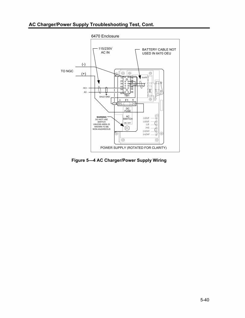
5-40
AC Charger/Power Supply Troubleshooting Test, Cont.
6470 Enclosure
POWER SUPPLY (ROTATED FOR CLARITY)
XMFR
(-)OUT
(-)OUT(-)S(+)S
(+)OUT(+)OUT
ACSWITCH
DCFUSE
ON OFF
WARNINGDO NOT USE
SWITCHUNLESS AREA ISKNOWN TO BE
NON-HAZARDOUS
115/230V AC IN
AC+
AC-
BATTERY CABLE NOT USED IN 6470 OEU
SHLD GND
(+)
(-)
1A
2A3A4A
1B2B3B
4B5B6B
5A
6ATB1
F1A B
TO NGC
Figure 5—4 AC Charger/Power Supply Wiring
5-41
Troubleshooting Communications
Overview
These troubleshooting procedures are applicable to an NGC8200 with an installed radio in the Optional Equipment Unit (OEU). Use Figure 5—5 as an aid for troubleshooting communication problems. The three basic types of radio communications that can be used between the NGC and a radio receiver, are: • RS-232 Communications (see Table 5-3 for Pin Configurations) • RS-485 Communications (see Table 5-4 for Pin Configurations) • RS-422 Communications (available, but not detailed) The radio/modem may be powered one of two ways. Always on, or Switched. Your specific system set up will determine what steps you need to power the Radio/Modem. When switching power to a radio with Inhibit (SLEEP) mode, the Serial Port 1 or 2 Switched Power line, will go to the radios inhibit (SLEEP) Mode input. Power out will go to the radios power input. Communication Troubleshooting the communications for this unit requires that equipment
in two areas be tested; 1) the NGC Comm Ports and 2) the external Communication device. This is discussed in more detail in the Communications Overview section. Other communication troubleshooting information is shared in the following categories: • RS-232 Communications • RS485 Communications • RS422 Communications
Setting Up Communication
After installation of communication equipment and before placing the communication system into operation, the user should note the following: • Verify field wiring terminations on the NGC Termination Panel. • Verify field wiring from NGC unit to Termination Strip inside the OEU
enclosure. • Verify Field wiring from Termination Strip to radio. • Check NGC identifier (ID). Log the ID for future reference. • Log NGC access security code, baud rate, listen cycle, protocol and
interface for future reference.
Continued on Next Page

5-42
Communications Overview, Cont.
12VCommunicationSupply Voltage
Test
START
Does UnitRespond to HostComm Request?
RS-232Communication
Test
YES NO
Verify unitID#, Security
Code andProtocol are
Correct.
NO
YES
Verify jumperand terminal &pin wiring are
correct.
ENDTransceiver
Supply voltagewithin Specs?
YES
Voltage supplyfrom NGC unit=10.5 VDC?
NO
InvestigatePower Supply
IssuesFigure 5-1
TransceiverComm Check
SubstituteCommunication
Test Cable
TransceiverSupply voltage
TestInvestigateTransceiver
Issues
Unit Respond toHost CommRequest?
YES
NO
RS-485Communication
Test
IsCommunication
RS-232?
YES
NOIsCommunication
RS-485?
YES
NO ContactTotalflowTechnicalSupport
Does UnitRespond?
NO
YES
Test Passed?NO
YES
Figure 5—5 Communication Troubleshooting Flowchart
Continued on Next Page

5-43
Communications Overview, Cont.
The following helpful hints aid the user after communication equipment has been installed and setup: • When communication equipment is powered/switched on, NGC
displays the Communication Icon after it recognizes the NGC ID and is responding.
• Check baud rate of NGC transmission and LISTEN time settings. The baud rate and time settings can be changed by entering the Station Setup screen from the Analyzer Operation screen. Default settings are 1200 baud and the listening time is 4 seconds and communications interface is turned off.
• Minimum power required for operating remote communications is 11.9 VDC (default), or as set by user. Should the power fall below this level, remote communications will be terminated.
• Test remote communications using RS-232 Troubleshooting Cable (2011781-xxx). Use RS-232 to RS-485 communication Converter (1800255-xxx) in conjunction with RS-232 Troubleshooting cable to test RS-485 remote communications.
Transceiver Supply Voltage Test
Using wiring information and guidelines supplied by transceiver manufacturer, verify that transceiver is receiving manufacturer’s suggested voltage. If unit is receiving sufficient voltage, continue to the OEU Wiring Voltage Test.
If transceiver is not receiving sufficient voltage, investigate power supply issues. These may involve wiring irregularities at either the AC Charger/Power Supply, XFC/XRC Board (6770 only), or at the Power Relay if using Relay for switching power to Radio.
12V Communication Supply Voltage Test
Instructions If Transceiver does not feature a SLEEP Mode and power is supplied through an optional Relay, begin with Step 1, Relay Supply Voltage Test. If Transceiver features a SLEEP Mode, or is continuously powered, begin with Step 2.
Continued on Next Page
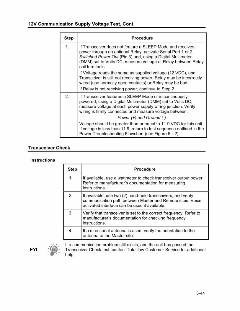
5-44
12V Communication Supply Voltage Test, Cont.
Step Procedure
1. If Transceiver does not feature a SLEEP Mode and receives power through an optional Relay, activate Serial Port 1 or 2 Switched Power Out (Pin 3) and, using a Digital Multimeter (DMM) set to Volts DC, measure voltage at Relay between Relay coil terminals. If Voltage reads the same as supplied voltage (12 VDC), and Transceiver is still not receiving power, Relay may be incorrectly wired (use normally open contacts) or Relay may be bad. If Relay is not receiving power, continue to Step 2.
2. If Transceiver features a SLEEP Mode or is continuously powered, using a Digital Multimeter (DMM) set to Volts DC, measure voltage at each power supply wiring junction. Verify wiring is firmly connected and measure voltage between:
Power (+) and Ground (-). Voltage should be greater than or equal to 11.9 VDC for this unit. If voltage is less than 11.9, return to test sequence outlined in the Power Troubleshooting Flowchart (see Figure 5—2).
Transceiver Check
Instructions
Step Procedure
1. If available, use a wattmeter to check transceiver output power. Refer to manufacturer’s documentation for measuring instructions.
2. If available, use two (2) hand-held transceivers, and verify communication path between Master and Remote sites. Voice activated interface can be used if available.
3. Verify that transceiver is set to the correct frequency. Refer to manufacturer’s documentation for checking frequency instructions.
4. If a directional antenna is used, verify the orientation to the antenna to the Master site.
If a communication problem still exists, and the unit has passed the Transceiver Check test, contact Totalflow Customer Service for additional help.

5-45
RS-232 Communication Test
The following RS-232 Serial Communication Test procedure is directed from Figure 5—5 and will assist the user in what may be the possible cause for indicated error message. Before performing this test, please verify that the field wiring is correct (see Table 5-3).
Table 5-3 RS-232 Field Wiring on NGC Termination Panel
Description Description
PIN Jack 8–Port 1 Jack 10–Port 2
1 Power Out Power Out 2 Ground Ground 3 Switched Power Out Switched Power Out 4 Operate Operate 5 Not Used Not Used 6 Request to Send Request to Send 7 Transmit Data Transmit Data 8 Receive Data Receive Data 9 Clear to Send Clear to Send
When troubleshooting RS-232 mode, verify termination settings of Serial Port 1 J9 and Serial Port 2 J11 on Termination Panel have pins 2 and 3 jumpered.
Instructions
Step Procedure
Voltage on the following steps may be hard to see using a Digital Multimeter. If available, an oscilloscope will provide a more accurate reading. To verify, the Host software must be continuously polling the NGC.
Generally speaking, these tests performed on the Terminal Board will only verify incorrect or damaged wiring. If all previous testing passed, and all wiring, jack and terminations have been verified correct, the board will need replaced. Contact Totalflow Customer Service. See “Getting Help” in the introduction of this manual for instructions.
1. Using an oscilloscope, measure Receiving Data voltage on Termination Panel J8 or J10 between:
Port 1, J8–Pin 2 (Ground) and Pin 8 (Receive Data) or Port 2, J10–Pin 2 (Ground) and Pin 8 (Receive Data).
When the unit is receiving data from Host, voltage should vary between -5 VDC and +5VDC. This would indicate that the unit is receiving data, continue to Step 2. If unit is not receiving data, investigate wiring issues (see Table 5-3).
Continued on Next Page

5-46
RS-232 Communication Test, Cont.
Step Procedure, Cont.
2. Using an oscilloscope, measure Request to Send voltage on Termination Panel J8 or J10 between:
Port 1, J8–Pin 2 (Ground) and Pin 6 (Request to Send) or Port 2, J10–Pin 2 (Ground) and Pin 6 (Request to Send).
When unit is communicating to with Host, voltage should be +5VDC and remain +5VDC until XFC transmit stops. This would indicate that the unit is transmitting data, continue to Step 3. If unit is not receiving data, investigate wiring issues (see Table 5-3).
3. Using an oscilloscope, measure Transmit Data voltage on Termination Panel J8 or J10 between:
Port 1, J8–Pin 2 (Ground) and Pin 7 (Transmit Data) or Port 2, J10–Pin 2 (Ground) and Pin 7 (Transmit Data).
When the unit is transmitting to Host, voltage should vary between -5 VDC and +5VDC. This would indicate that the unit is transmitting data. If unit is still not responding, continue to next test as directed in Figure 5—5.
RS-485 Communications
The following RS-485 Serial Communication Test procedure is directed from Figure 5—5 and will assist the user in what may be the possible cause for indicated error message. Before performing this test, please verify that the field wiring is correct (see Table 5-3).
When troubleshooting RS-485 mode, verify termination settings of Port 1 J9 and Port 2 J11 on Termination Panel are correctly jumpered (see Table 5-4).
Table 5-4 RS-485 Terminations
Serial Comm Port 1 2
Jumper J9 J11
First or Intermediate Unit Pins 2–3 Pins 2–3
Last or Only Unit Pins 1–2 Pins 1–2

5-47
RS-485 Communication Test
Before performing this test on the Termination Panel located inside the Rear End Cap, please verify that the wiring is correct (see Table 5-5).
Table 5-5 RS-485 Field Wiring on NGC Termination Panel
Description Description
PIN J8–Port 1 J10–Port 2
1 Power Power 2 Ground Ground 3 Switched Power Out Switched Power Out 4 Operate Operate 5 Remote Request to Send Remote Request to Send 6 Transmit Bus (+) Transmit Bus (+) 7 Transmit Bus (-) Transmit Bus (-) 8 Receive Bus (+) (RS-422) Receive Bus (+) (RS-422) 9 Receive Bus (-) (RS-422) Receive Bus (-) (RS-422)
Instructions
Voltage on the following steps may be hard to see using a Digital Multimeter. If available, an oscilloscope will provide a more accurate reading. To verify, the Host software must be continuously polling the meter.
Generally speaking, these tests performed on the Termination Panel will only verify incorrect or damaged wiring. If all previous testing passed, and all wiring, jack and terminations have been verified correct, the Termination Panel may need replaced, but does not typically fail. Contact Totalflow Customer Service. See “Getting Help” in the introduction of this manual for instructions.
Step Procedure
1. Using an oscilloscope, measure Line Driver voltage on Termination Panel J8 or J10 between:
Port 1, J8–Pin 7 (BUS-) and Pin 6 (BUS+) or Port 2, J10–Pin 7 (BUS-) and Pin 6 (BUS+).
When the unit is receiving data from Host, voltage should vary between +5 VDC and 0 VDC. This would indicate that the unit is receiving data.
Continued on Next Page

5-48
Termination Panel RS-485 Communication Test, Cont.
Step Procedure, Cont.
2. Using an oscilloscope, measure Remote Request to Send voltage on Termination Panel J8 or J10:
Port 1, J8–Pin 2 (Ground) and Pin 5 (RRTS) Port 2, J10–Pin 2 (Ground) and Pin 5 (RRTS)
When the unit is transmitting data, voltage should vary between +5 VDC and 0 VDC. This would indicate that the RRTS is working correctly.
3. If any inaccuracy exists, investigate wiring errors or damaged wires.
If a communication problem still exists, and the unit has passed the tests in steps 1 and 2, additional testing will be required.

A-1
Appendix A Modbus Registers
Modbus Reg # Input Reg Description
Component Index for Stream App.Array.Index = xx.17.yy 3001 18.200.0 Component Table #1 Component Index #1(C3) 3002 18.200.1 Component Table #1 Component Index #2(IC4) 3003 18.200.2 Component Table #1 Component Index #3(NC4) 3004 18.200.3 Component Table #1 Component Index #4(Neo C5) 3005 18.200.4 Component Table #1 Component Index #5(IC5) 3006 18.200.5 Component Table #1 Component Index #6(NC5) 3007 18.200.6 Component Table #1 Component Index #7(C6+) 3008 18.200.7 Component Table #1 Component Index #8(N2) 3009 18.200.8 Component Table #1 Component Index #9(C1) 3010 18.200.9 Component Table #1 Component Index #10(CO2) 3011 18.200.10 Component Table #1 Component Index #11(C4+) 3012 18.200.11 Component Table #1 Component Index #12(C9) 3013 18.200.12 Component Table #1 Component Index #13(C2) 3014 18.200.13 Component Table #1 Component Index #14(C6) 3015 18.200.14 Component Table #1 Component Index #15(C7) 3016 18.200.15 Component Table #1 Component Index #16(C8)
3017 18.200.0 Component Table #2 Component Index #1 3018 18.200.1 Component Table #2 Component Index #2 3019 18.200.2 Component Table #2 Component Index #3 3020 18.200.3 Component Table #2 Component Index #4 3021 18.200.4 Component Table #2 Component Index #5 3022 18.200.5 Component Table #2 Component Index #6 3023 18.200.6 Component Table #2 Component Index #7 3024 18.200.7 Component Table #2 Component Index #8 3025 18.200.8 Component Table #2 Component Index #9 3026 18.200.9 Component Table #2 Component Index #10 3027 18.200.10 Component Table #2 Component Index #11 3028 18.200.11 Component Table #2 Component Index #12 3029 18.200.12 Component Table #2 Component Index #13 3030 18.200.13 Component Table #2 Component Index #14 3031 18.200.14 Component Table #2 Component Index #15 3032 18.200.15 Component Table #2 Component Index #16 3033 18.201.1 Analysis Time (in1/30ths of 1 second) (N/A) 3034 18.201.0 Current Stream Number(15.0.28) 3035 18.201.1 Mask of streams associated with Component Table 41 (N/A)

A-2
Modbus Reg # Input Reg Description 3036 18.201.3 Current Month (1-12) (15.1.8) 3037 18.201.4 Current Day (1-31) (15.1.9) 3038 18.201.5 Current Year (0-99) (15.1.10) 3039 18.201.6 Current Hour (0-24) (15.1.11) 3040 18.201.7 Current Minutes (0-59) (15.1.12) 3041 18.201.8 Cycle Start Month (1-12) (15.1.13) 3042 18.201.9 Cycle Start Day (1-31) (15.1.14) 3043 18.201.10 Cycle Start Year (0-99) (15.1.15) 3044 18.201.11 Cycle Start Hour (0-24) (15.1.16) 3045 18.201.12 Cycle Start Minutes (0-59) (15.1.17) 3046 18.201.42 Bit Flags Transmitter 3047 18.201.43 Bit Flags Transmitter 3048 18.201.1 Bit Flags Stream #1 Low (N/A) 3049 18.201.1 Bit Flags Stream #1 High (N/A) 3050 18.201.1 Bit Flags Stream #2 Low (N/A) 3051 18.201.1 Bit Flags Stream #2 High (N/A) 3052 18.201.1 Bit Flags Stream #3 Low (N/A) 3053 18.201.1 Bit Flags Stream #3 High (N/A) 3054 18.201.1 Bit Flags Stream #4 Low (N/A) 3055 18.201.1 Bit Flags Stream #4 High (N/A) 3056 18.201.1 Bit Flags Stream #5 Low (N/A) 3057 18.201.1 Bit Flags Stream #5 High (N/A)
Int16 for Stream App.Array.Index = xx.1.yy
3058 18.201.2 New Data Flag(15.1.7) 3059 18.201.13 Cal/Analysis Flag(15.1.18)
3060 18.201.32 Read the Current State (19.1.0) 3061 18.201.33 Read the Next State (19.1.0) 3062 18.201.1 Auto Calibration During Start-up (N/A) 3063 18.201.22 Alternate Purge Cycles (15.0.24) 3064 18.201.23 Alternate Calibration Cycles (15.0.19) 3065 18.201.24 Number of Purge Cycles (15.0.23) 3066 18.201.25 Number of Calibration Cycles (15.0.18) 3067 18.201.1 Low Carrier Mode (N/A) 3068 18.201.1 Low Power Mode (N/A) 3069 18.201.1 Pre-Purge Selection (Future) 3070 18.201.1 Normal Status (N/A) 3071 18.201.1 Fault Status (N/A) 3072 18.201.26 Carrier Bottle Low (DI1) (11.0.0) 3073 18.201.27 Calibration Bottle Low (DI2) (11.0

A-3
Modbus Reg # Input Reg Description 3074 18.201.1 Manual Update Response Factors (N/A) 3075 18.201.1 Auto Update Response Factors (N/A) 3076 18.201.1 Disable Stream Switching (N/A) 3077 18.201.1 Transmitter Current Warning (N/A) 3078 18.201.1 Transmitter Current Fault (N/A) 3079 18.201.1 Transmitter Initial Warning (N/A) 3080 18.201.1 Transmitter Initial Fault (N/A) 3081 18.201.18 Stream #1 Current Warning (15.128.1) 3082 18.201.19 Stream #2 Current Warning (16.128.1) 3083 18.201.20 Stream #3 Current Warning (17.128.1) 3084 18.201.21 Stream #4 Current Warning (18.128.1) 3085 18.201.14 Stream #1 Current Fault (15.128.0) 3086 18.201.15 Stream #2 Current Fault (16.128.0) 3087 18.201.16 Stream #3 Current Fault (17.128.0) 3088 18.201.17 Stream #4 Current Fault (18.128.0) 3089 18.201.38 Stream #1 Initial Warning (15.128.3) 3090 18.201.39 Stream #2 Initial Warning (16.128.3) 3091 18.201.40 Stream #3 Initial Warning (17.128.3) 3092 18.201.41 Stream #4 Initial Warning (18.128.3) 3093 18.201.34 Stream #1 Initial Fault (15.128.2) 3094 18.201.35 Stream #2 Initial Fault (16.128.2) 3095 18.201.36 Stream #3 Initial Fault (17.128.2) 3096 18.201.37 Stream #4 Initial Fault (18.128.2) 3097 18.201.28 Stream #1 Skip Flag (19.0.7) 3098 18.201.29 Stream #2 Skip Flag (19.0.8) 3099 18.201.30 Stream #3 Skip Flag (19.0.9) 3100 18.201.31 Stream #4 Skip Flag (19.0.10)
5001 18.208.2 Cycle Clock (19.2.2) 5002 18.208.1 Cycle Time (19.2.1) 5003 18.208.0 Detector 0 (N/A)) 5004 18.208.0 Detector 1 (N/A)) 5005 18.208.0 Detector 2 (N/A) 5006 18.208.0 Detector 3 (N/A)
Mole % for Stream App.Array.Index = xx.7.yy
7001 18.203.0 Mole % - Component #1 7002 18.203.1 Mole % - Component #2 7003 18.203.2 Mole % - Component #3 7004 18.203.3 Mole % - Component #4 7005 18.203.4 Mole % - Component #5

A-4
Modbus Reg # Input Reg Description 7006 18.203.5 Mole % - Component #6 7007 18.203.6 Mole % - Component #7 7008 18.203.7 Mole % - Component #8 7009 18.203.8 Mole % - Component #9 7010 18.203.9 Mole % - Component #10 7011 18.203.10 Mole % - Component #11 7012 18.203.11 Mole % - Component #12 7013 18.203.12 Mole % - Component #13 7014 18.203.13 Mole % - Component #14 7015 18.203.14 Mole % - Component #15 7016 18.203.15 Mole % - Component #16
GPM % for Stream App.Array.Index = xx.11.yy
7017 18.204.0 GPM % - Component #1 7018 18.204.1 GPM % - Component #2 7019 18.204.2 GPM % - Component #3 7020 18.204.3 GPM % - Component #4 7021 18.204.4 GPM % - Component #5 7022 18.204.5 GPM % - Component #6 7023 18.204.6 GPM % - Component #7 7024 18.204.7 GPM % - Component #8 7025 18.204.8 GPM % - Component #9 7026 18.204.9 GPM % - Component #10 7027 18.204.10 GPM % - Component #11 7028 18.204.11 GPM % - Component #12 7029 18.204.12 GPM % - Component #13 7030 18.204.13 GPM % - Component #14 7031 18.204.14 GPM % - Component #15 7032 18.204.15 GPM % - Component #16
Floats for Stream App.Array.Index = xx.4.yy
7033 18.202.0 BTU - Dry(15.4.5) 7034 18.202.1 BTU - Saturated(15.4.6) 7035 18.202.2 Specific Gravity(15.4.9) 7036 18.202.3 Compressibility(15.4.11) 7037 18.202.4 WOBBE Index(15.4.7) 7038 18.202.6 Total UN-normalized mole(15.4.12)
7039 18.202.13 Total GPM (15.4.13) 7040 18.202.8 Ideal BTU (15.4.4) 7041 18.202.9 Density Normal (15.4.10)

A-5
Modbus Reg # Input Reg Description 7042 18.202.10 Inferior WOBBE (15.4.8) 7043 18.202.11 Methane Number (15.4.27) 7044 18.202.12 Speed of Sound (15.4.54)
7045 18.241.0 Rolling Average #1 7046 18.241.1 Rolling Average #2 7047 18.241.2 Rolling Average #3 7048 18.241.3 Rolling Average #4 7049 18.241.4 Rolling Average #5 7050 18.241.5 Rolling Average #6 7051 18.241.6 Rolling Average #7 7052 18.241.7 Rolling Average #8 7053 18.241.8 Rolling Average #9 7054 18.241.9 Rolling Average #10 7055 18.241.10 Rolling Average #11 7056 18.241.11 Rolling Average #12 7057 18.241.12 Rolling Average #13 7058 18.241.13 Rolling Average #14 7059 18.241.14 Rolling Average #15 7060 18.241.15 Rolling Average #16
7061 18.206.0 24 Hour Average for Component #1 7062 18.206.1 24 Hour Average for Component #2 7063 18.206.2 24 Hour Average for Component #3 7064 18.206.3 24 Hour Average for Component #4 7065 18.206.4 24 Hour Average for Component #5 7066 18.206.5 24 Hour Average for Component #6 7067 18.206.6 24 Hour Average for Component #7 7068 18.206.7 24 Hour Average for Component #8 7069 18.206.8 24 Hour Average for Component #9 7070 18.206.9 24 Hour Average for Component #10 7071 18.206.10 24 Hour Average for Component #11 7072 18.206.11 24 Hour Average for Component #12 7073 18.206.12 24 Hour Average for Component #13 7074 18.206.13 24 Hour Average for Component #14 7075 18.206.14 24 Hour Average for Component #15 7076 18.206.15 24 Hour Average for Component #16 7077 18.207.0 Previous 24 Hour Average for Component #1 7078 18.207.1 Previous 24 Hour Average for Component #2 7079 18.207.2 Previous 24 Hour Average for Component #3 7080 18.207.3 Previous 24 Hour Average for Component #4

A-6
Modbus Reg # Input Reg Description 7081 18.207.4 Previous 24 Hour Average for Component #5 7082 18.207.5 Previous 24 Hour Average for Component #6 7083 18.207.6 Previous 24 Hour Average for Component #7 7084 18.207.7 Previous 24 Hour Average for Component #8 7085 18.207.8 Previous 24 Hour Average for Component #9 7086 18.207.9 Previous 24 Hour Average for Component #10 7087 18.207.10 Previous 24 Hour Average for Component #11 7088 18.207.11 Previous 24 Hour Average for Component #12 7089 18.207.12 Previous 24 Hour Average for Component #13 7090 18.207.13 Previous 24 Hour Average for Component #14 7091 18.207.14 Previous 24 Hour Average for Component #15 7092 18.207.15 Previous 24 Hour Average for Component #16
Floating Point Register Group - Transmitter
7200 18.202.7 Ground Reference (N/A) 7201 18.202.18 Power (12.247.9) 7202 18.202.19 Mandrel Temp (12.247.7) 7203 18.202.20 Column 1 Pressure (12.247.5) 7204 18.202.21 Column 2 Pressure (12.247.6) 7205 18.202.7 Analog Input #6 - Spare (N/A) 7206 18.202.7 Ambient Temp (N/A) 7207 18.202.7 Voltage Reference (N/A) 7208 18.202.7 (N/A) 7209 18.233.0 Calibration Standard - Component #1 (15.31.0) 7210 18.233.1 Calibration Standard - Component #2 (15.31.1) 7211 18.233.2 Calibration Standard - Component #3 (15.31.2) 7212 18.233.3 Calibration Standard - Component #4 (15.31.3) 7213 18.233.4 Calibration Standard - Component #5 (15.31.4) 7214 18.233.5 Calibration Standard - Component #6 (15.31.5) 7215 18.233.6 Calibration Standard - Component #7 (15.31.6) 7216 18.233.7 Calibration Standard - Component #8 (15.31.7) 7217 18.233.8 Calibration Standard - Component #9 (15.31.8) 7218 18.233.9 Calibration Standard - Component #10 (15.31.9) 7219 18.233.10 Calibration Standard - Component #11 (15.31.10) 7220 18.233.11 Calibration Standard - Component #12 (15.31.11) 7221 18.233.12 Calibration Standard - Component #13 (15.31.12) 7222 18.233.13 Calibration Standard - Component #14 (15.31.13) 7223 18.233.14 Calibration Standard - Component #15 (15.31.14) 7224 18.233.15 Calibration Standard - Component #16 (15.31.15) 7225 18.205.0 Response Factor - Component #1 (15.5.0) 7226 18.205.1 Response Factor - Component #2 (15.5.1)

A-7
Modbus Reg # Input Reg Description 7227 18.205.2 Response Factor - Component #3 (15.5.2) 7228 18.205.3 Response Factor - Component #4 (15.5.3) 7229 18.205.4 Response Factor - Component #5 (15.5.4) 7230 18.205.5 Response Factor - Component #6 (15.5.5) 7231 18.205.6 Response Factor - Component #7 (15.5.6) 7232 18.205.7 Response Factor - Component #8 (15.5.7) 7233 18.205.8 Response Factor - Component #9 (15.5.8) 7234 18.205.9 Response Factor - Component #10 (15.5.9) 7235 18.205.10 Response Factor - Component #11 (15.5.10) 7236 18.205.11 Response Factor - Component #12 (15.5.11) 7237 18.205.12 Response Factor - Component #13 (15.5.12) 7238 18.205.13 Response Factor - Component #14 (15.5.13) 7239 18.205.14 Response Factor - Component #15 (15.5.14) 7240 18.205.15 Response Factor - Component #16 (15.5.15) 7241 18.239.0 Alt Calibration Standard - Component #1 (15.40.0) 7242 18.239.1 Alt Calibration Standard - Component #2 (15.40.1) 7243 18.239.2 Alt Calibration Standard - Component #3 (15.40.2) 7244 18.239.3 Alt Calibration Standard - Component #4 (15.40.3) 7245 18.239.4 Alt Calibration Standard - Component #5 (15.40.4) 7246 18.239.5 Alt Calibration Standard - Component #6 (15.40.5) 7247 18.239.6 Alt Calibration Standard - Component #7 (15.40.6) 7248 18.239.7 Alt Calibration Standard - Component #8 (15.40.7) 7249 18.239.8 Alt Calibration Standard - Component #9 (15.40.8) 7250 18.239.9 Alt Calibration Standard - Component #10 (15.40.9) 7251 18.239.10 Alt Calibration Standard - Component #11 (15.40.10) 7252 18.239.11 Alt Calibration Standard - Component #12 (15.40.11) 7253 18.239.12 Alt Calibration Standard - Component #13 (15.40.12) 7254 18.239.13 Alt Calibration Standard - Component #14 (15.40.13) 7255 18.239.14 Alt Calibration Standard - Component #15 (15.40.14) 7256 18.239.15 Alt Calibration Standard - Component #16 (15.40.15) 7257 18.240.0 Alt Response Factor - Component #1 (15.43.0) 7258 18.240.1 Alt Response Factor - Component #2 (15.43.1) 7259 18.240.2 Alt Response Factor - Component #3 (15.43.2) 7260 18.240.3 Alt Response Factor - Component #4 (15.43.3) 7261 18.240.4 Alt Response Factor - Component #5 (15.43.4) 7262 18.240.5 Alt Response Factor - Component #6 (15.43.5) 7263 18.240.6 Alt Response Factor - Component #7 (15.43.6) 7264 18.240.7 Alt Response Factor - Component #8 (15.43.7) 7265 18.240.8 Alt Response Factor - Component #9 (15.43.8) 7266 18.240.9 Alt Response Factor - Component #10 (15.43.9) 7267 18.240.10 Alt Response Factor - Component #11 (15.43.10)

A-8
Modbus Reg # Input Reg Description 7268 18.240.11 Alt Response Factor - Component #12 (15.43.11) 7269 18.240.12 Alt Response Factor - Component #13 (15.43.12) 7270 18.240.13 Alt Response Factor - Component #14 (15.43.13) 7271 18.240.14 Alt Response Factor - Component #15 (15.43.14) 7272 18.240.15 Alt Response Factor - Component #16 (15.43.15)
7273 18.202.14 Detector 0 value (12.247.0) 7274 18.202.15 Detector 1 value (12.247.1) 7275 18.202.16 Detector 2 value (12.247.2) 7276 18.202.17 Detector 3 value (12.247.3)
Registers 7400-7599 are for stream #1
7401 18.210.0 Mole % - Component #1 7402 18.210.1 Mole % - Component #2 7403 18.210.2 Mole % - Component #3 7404 18.210.3 Mole % - Component #4 7405 18.210.4 Mole % - Component #5 7406 18.210.5 Mole % - Component #6 7407 18.210.6 Mole % - Component #7 7408 18.210.7 Mole % - Component #8 7409 18.210.8 Mole % - Component #9 7410 18.210.9 Mole % - Component #10 7411 18.210.10 Mole % - Component #11 7412 18.210.11 Mole % - Component #12 7413 18.210.12 Mole % - Component #13 7414 18.210.13 Mole % - Component #14 7415 18.210.14 Mole % - Component #15 7416 18.210.15 Mole % - Component #16 7417 18.211.0 GPM % - Component #1 7418 18.211.1 GPM % - Component #2 7419 18.211.2 GPM % - Component #3 7420 18.211.3 GPM % - Component #4 7421 18.211.4 GPM % - Component #5 7422 18.211.5 GPM % - Component #6 7423 18.211.6 GPM % - Component #7 7424 18.211.7 GPM % - Component #8 7425 18.211.8 GPM % - Component #9 7426 18.211.9 GPM % - Component #10 7427 18.211.10 GPM % - Component #11 7428 18.211.11 GPM % - Component #12 7429 18.211.12 GPM % - Component #13

A-9
Modbus Reg # Input Reg Description 7430 18.211.13 GPM % - Component #14 7431 18.211.14 GPM % - Component #15 7432 18.211.15 GPM % - Component #16
7433 18.209.0 BTU - Dry 7434 18.209.1 BTU - Saturated 7435 18.209.2 Specific Gravity 7436 18.209.3 Compressibility 7437 18.209.4 WOBBE Index 7438 18.209.5 Total UN-normalized mole
7439 18.209.11 Total GPM 7440 18.209.6 Ideal BTU 7441 18.209.7 Density Normal 7442 18.209.8 Inferior WOBBE 7443 18.209.9 Methane Number 7444 18.209.10 Speed of Sound
7445 18.235.0 Rolling Average #1 7446 18.235.1 Rolling Average #2 7447 18.235.2 Rolling Average #3 7448 18.235.3 Rolling Average #4 7449 18.235.4 Rolling Average #5 7450 18.235.5 Rolling Average #6 7451 18.235.6 Rolling Average #7 7452 18.235.7 Rolling Average #8 7453 18.235.8 Rolling Average #9 7454 18.235.9 Rolling Average #10 7455 18.235.10 Rolling Average #11 7456 18.235.11 Rolling Average #12 7457 18.235.12 Rolling Average #13 7458 18.235.13 Rolling Average #14 7459 18.235.14 Rolling Average #15 7460 18.235.15 Rolling Average #16
7461 18.212.0 24 Hour Average for Component #1 7462 18.212.1 24 Hour Average for Component #2 7463 18.212.2 24 Hour Average for Component #3 7464 18.212.3 24 Hour Average for Component #4 7465 18.212.4 24 Hour Average for Component #5 7466 18.212.5 24 Hour Average for Component #6

A-10
Modbus Reg # Input Reg Description 7467 18.212.6 24 Hour Average for Component #7 7468 18.212.7 24 Hour Average for Component #8 7469 18.212.8 24 Hour Average for Component #9 7470 18.212.9 24 Hour Average for Component #10 7471 18.212.10 24 Hour Average for Component #11 7472 18.212.11 24 Hour Average for Component #12 7473 18.212.12 24 Hour Average for Component #13 7474 18.212.13 24 Hour Average for Component #14 7475 18.212.14 24 Hour Average for Component #15 7476 18.212.15 24 Hour Average for Component #16 7477 18.213.0 Previous 24 Hour Average for Component #1 7478 18.213.1 Previous 24 Hour Average for Component #2 7479 18.213.2 Previous 24 Hour Average for Component #3 7480 18.213.3 Previous 24 Hour Average for Component #4 7481 18.213.4 Previous 24 Hour Average for Component #5 7482 18.213.5 Previous 24 Hour Average for Component #6 7483 18.213.6 Previous 24 Hour Average for Component #7 7484 18.213.7 Previous 24 Hour Average for Component #8 7485 18.213.8 Previous 24 Hour Average for Component #9 7486 18.213.9 Previous 24 Hour Average for Component #10 7487 18.213.10 Previous 24 Hour Average for Component #11 7488 18.213.11 Previous 24 Hour Average for Component #12 7489 18.213.12 Previous 24 Hour Average for Component #13 7490 18.213.13 Previous 24 Hour Average for Component #14 7491 18.213.14 Previous 24 Hour Average for Component #15 7492 18.213.15 Previous 24 Hour Average for Component #16
Registers 7600-7799 are for stream #2
7601 18.215.0 Mole % - Component #1 7602 18.215.1 Mole % - Component #2 7603 18.215.2 Mole % - Component #3 7604 18.215.3 Mole % - Component #4 7605 18.215.4 Mole % - Component #5 7606 18.215.5 Mole % - Component #6 7607 18.215.6 Mole % - Component #7 7608 18.215.7 Mole % - Component #8 7609 18.215.8 Mole % - Component #9 7610 18.215.9 Mole % - Component #10 7611 18.215.10 Mole % - Component #11 7612 18.215.11 Mole % - Component #12 7613 18.215.12 Mole % - Component #13
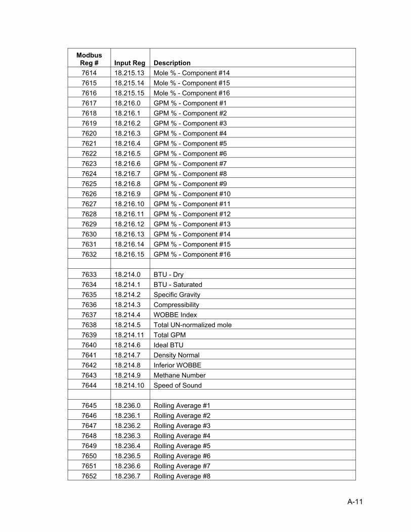
A-11
Modbus Reg # Input Reg Description 7614 18.215.13 Mole % - Component #14 7615 18.215.14 Mole % - Component #15 7616 18.215.15 Mole % - Component #16 7617 18.216.0 GPM % - Component #1 7618 18.216.1 GPM % - Component #2 7619 18.216.2 GPM % - Component #3 7620 18.216.3 GPM % - Component #4 7621 18.216.4 GPM % - Component #5 7622 18.216.5 GPM % - Component #6 7623 18.216.6 GPM % - Component #7 7624 18.216.7 GPM % - Component #8 7625 18.216.8 GPM % - Component #9 7626 18.216.9 GPM % - Component #10 7627 18.216.10 GPM % - Component #11 7628 18.216.11 GPM % - Component #12 7629 18.216.12 GPM % - Component #13 7630 18.216.13 GPM % - Component #14 7631 18.216.14 GPM % - Component #15 7632 18.216.15 GPM % - Component #16
7633 18.214.0 BTU - Dry 7634 18.214.1 BTU - Saturated 7635 18.214.2 Specific Gravity 7636 18.214.3 Compressibility 7637 18.214.4 WOBBE Index 7638 18.214.5 Total UN-normalized mole 7639 18.214.11 Total GPM 7640 18.214.6 Ideal BTU 7641 18.214.7 Density Normal 7642 18.214.8 Inferior WOBBE 7643 18.214.9 Methane Number 7644 18.214.10 Speed of Sound
7645 18.236.0 Rolling Average #1 7646 18.236.1 Rolling Average #2 7647 18.236.2 Rolling Average #3 7648 18.236.3 Rolling Average #4 7649 18.236.4 Rolling Average #5 7650 18.236.5 Rolling Average #6 7651 18.236.6 Rolling Average #7 7652 18.236.7 Rolling Average #8
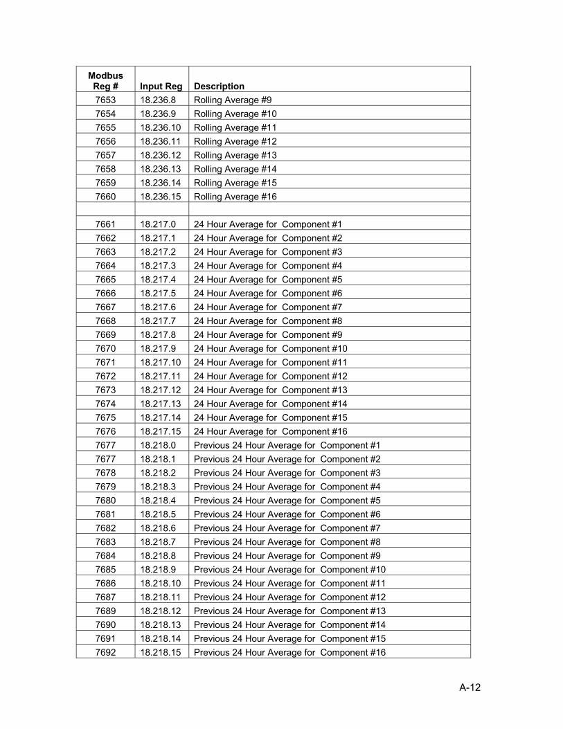
A-12
Modbus Reg # Input Reg Description 7653 18.236.8 Rolling Average #9 7654 18.236.9 Rolling Average #10 7655 18.236.10 Rolling Average #11 7656 18.236.11 Rolling Average #12 7657 18.236.12 Rolling Average #13 7658 18.236.13 Rolling Average #14 7659 18.236.14 Rolling Average #15 7660 18.236.15 Rolling Average #16
7661 18.217.0 24 Hour Average for Component #1 7662 18.217.1 24 Hour Average for Component #2 7663 18.217.2 24 Hour Average for Component #3 7664 18.217.3 24 Hour Average for Component #4 7665 18.217.4 24 Hour Average for Component #5 7666 18.217.5 24 Hour Average for Component #6 7667 18.217.6 24 Hour Average for Component #7 7668 18.217.7 24 Hour Average for Component #8 7669 18.217.8 24 Hour Average for Component #9 7670 18.217.9 24 Hour Average for Component #10 7671 18.217.10 24 Hour Average for Component #11 7672 18.217.11 24 Hour Average for Component #12 7673 18.217.12 24 Hour Average for Component #13 7674 18.217.13 24 Hour Average for Component #14 7675 18.217.14 24 Hour Average for Component #15 7676 18.217.15 24 Hour Average for Component #16 7677 18.218.0 Previous 24 Hour Average for Component #1 7677 18.218.1 Previous 24 Hour Average for Component #2 7678 18.218.2 Previous 24 Hour Average for Component #3 7679 18.218.3 Previous 24 Hour Average for Component #4 7680 18.218.4 Previous 24 Hour Average for Component #5 7681 18.218.5 Previous 24 Hour Average for Component #6 7682 18.218.6 Previous 24 Hour Average for Component #7 7683 18.218.7 Previous 24 Hour Average for Component #8 7684 18.218.8 Previous 24 Hour Average for Component #9 7685 18.218.9 Previous 24 Hour Average for Component #10 7686 18.218.10 Previous 24 Hour Average for Component #11 7687 18.218.11 Previous 24 Hour Average for Component #12 7689 18.218.12 Previous 24 Hour Average for Component #13 7690 18.218.13 Previous 24 Hour Average for Component #14 7691 18.218.14 Previous 24 Hour Average for Component #15 7692 18.218.15 Previous 24 Hour Average for Component #16

A-13
Modbus Reg # Input Reg Description
Registers 7800-7999 are for stream #3
7801 18.220.0 Mole % - Component #1 7802 18.220.1 Mole % - Component #2 7803 18.220.2 Mole % - Component #3 7804 18.220.3 Mole % - Component #4 7805 18.220.4 Mole % - Component #5 7806 18.220.5 Mole % - Component #6 7807 18.220.6 Mole % - Component #7 7808 18.220.7 Mole % - Component #8 7809 18.220.8 Mole % - Component #9 7810 18.220.9 Mole % - Component #10 7811 18.220.10 Mole % - Component #11 7812 18.220.11 Mole % - Component #12 7813 18.220.12 Mole % - Component #13 7814 18.220.13 Mole % - Component #14 7815 18.220.14 Mole % - Component #15 7816 18.220.15 Mole % - Component #16 7817 18.221.0 GPM % - Component #1 7818 18.221.1 GPM % - Component #2 7819 18.221.2 GPM % - Component #3 7820 18.221.3 GPM % - Component #4 7821 18.221.4 GPM % - Component #5 7822 18.221.5 GPM % - Component #6 7823 18.221.6 GPM % - Component #7 7824 18.221.7 GPM % - Component #8 7825 18.221.8 GPM % - Component #9 7826 18.221.9 GPM % - Component #10 7827 18.221.10 GPM % - Component #11 7828 18.221.11 GPM % - Component #12 7829 18.221.12 GPM % - Component #13 7830 18.221.13 GPM % - Component #14 7831 18.221.14 GPM % - Component #15 7832 18.221.15 GPM % - Component #16
7833 18.219.0 BTU - Dry 7834 18.219.1 BTU - Saturated 7835 18.219.2 Specific Gravity 7836 18.219.3 Compressibility 7837 18.219.4 WOBBE Index 7838 18.219.5 Total UN-normalized mole

A-14
Modbus Reg # Input Reg Description 7839 18.219.11 Total GPM 7840 18.219.6 Ideal BTU 7841 18.219.7 Density Normal 7842 18.219.8 Inferior WOBBE 7843 18.219.9 Methane Number 7844 18.219.10 Speed of Sound
7845 18.237.0 Rolling Average #1 7846 18.237.1 Rolling Average #2 7847 18.237.2 Rolling Average #3 7848 18.237.3 Rolling Average #4 7849 18.237.4 Rolling Average #5 7850 18.237.5 Rolling Average #6 7851 18.237.6 Rolling Average #7 7852 18.237.7 Rolling Average #8 7853 18.237.8 Rolling Average #9 7854 18.237.9 Rolling Average #10 7855 18.237.10 Rolling Average #11 7856 18.237.11 Rolling Average #12 7857 18.237.12 Rolling Average #13 7858 18.237.13 Rolling Average #14 7859 18.237.14 Rolling Average #15 7860 18.237.15 Rolling Average #16
7861 18.222.0 24 Hour Average for Component #1 7862 18.222.1 24 Hour Average for Component #2 7863 18.222.2 24 Hour Average for Component #3 7864 18.222.3 24 Hour Average for Component #4 7865 18.222.4 24 Hour Average for Component #5 7866 18.222.5 24 Hour Average for Component #6 7867 18.222.6 24 Hour Average for Component #7 7868 18.222.7 24 Hour Average for Component #8 7869 18.222.8 24 Hour Average for Component #9 7870 18.222.9 24 Hour Average for Component #10 7871 18.222.10 24 Hour Average for Component #11 7872 18.222.11 24 Hour Average for Component #12 7873 18.222.12 24 Hour Average for Component #13 7874 18.222.13 24 Hour Average for Component #14 7875 18.222.14 24 Hour Average for Component #15 7876 18.222.15 24 Hour Average for Component #16 7877 18.223.0 Previous 24 Hour Average for Component #1

A-15
Modbus Reg # Input Reg Description 7878 18.223.1 Previous 24 Hour Average for Component #2 7879 18.223.2 Previous 24 Hour Average for Component #3 7880 18.223.3 Previous 24 Hour Average for Component #4 7881 18.223.4 Previous 24 Hour Average for Component #5 7882 18.223.5 Previous 24 Hour Average for Component #6 7883 18.223.6 Previous 24 Hour Average for Component #7 7884 18.223.7 Previous 24 Hour Average for Component #8 7885 18.223.8 Previous 24 Hour Average for Component #9 7886 18.223.9 Previous 24 Hour Average for Component #10 7887 18.223.10 Previous 24 Hour Average for Component #11 7888 18.223.11 Previous 24 Hour Average for Component #12 7889 18.223.12 Previous 24 Hour Average for Component #13 7890 18.223.13 Previous 24 Hour Average for Component #14 7891 18.223.14 Previous 24 Hour Average for Component #15 7892 18.223.15 Previous 24 Hour Average for Component #16
Registers 8000-8199 are for stream #4
8001 18.225.0 Mole % - Component #1 8002 18.225.1 Mole % - Component #2 8003 18.225.2 Mole % - Component #3 8004 18.225.3 Mole % - Component #4 8005 18.225.4 Mole % - Component #5 8006 18.225.5 Mole % - Component #6 8007 18.225.6 Mole % - Component #7 8008 18.225.7 Mole % - Component #8 8009 18.225.8 Mole % - Component #9 8010 18.225.9 Mole % - Component #10 8011 18.225.10 Mole % - Component #11 8012 18.225.11 Mole % - Component #12 8013 18.225.12 Mole % - Component #13 8014 18.225.13 Mole % - Component #14 8015 18.225.14 Mole % - Component #15 8016 18.225.15 Mole % - Component #16 8017 18.226.0 GPM % - Component #1 8018 18.226.1 GPM % - Component #2 8019 18.226.2 GPM % - Component #3 8020 18.226.3 GPM % - Component #4 8021 18.226.4 GPM % - Component #5 8022 18.226.5 GPM % - Component #6 8023 18.226.6 GPM % - Component #7 8024 18.226.7 GPM % - Component #8

A-16
Modbus Reg # Input Reg Description 8025 18.226.8 GPM % - Component #9 8026 18.226.9 GPM % - Component #10 8027 18.226.10 GPM % - Component #11 8028 18.226.11 GPM % - Component #12 8029 18.226.12 GPM % - Component #13 8030 18.226.13 GPM % - Component #14 8031 18.226.14 GPM % - Component #15 8032 18.226.15 GPM % - Component #16
8033 18.224.0 BTU - Dry 8034 18.224.1 BTU - Saturated 8035 18.224.2 Specific Gravity 8036 18.224.3 Compressibility 8037 18.224.4 WOBBE Index 8038 18.224.5 Total UN-normalized mole 8039 18.224.11 Total GPM 8040 18.214.6 Ideal BTU 8041 18.214.7 Density Normal 8042 18.214.8 Inferior WOBBE 8043 18.214.9 Methane Number 8044 18.214.10 Speed of Sound
8045 18.238.0 Rolling Average #1 8046 18.238.1 Rolling Average #2 8047 18.238.2 Rolling Average #3 8048 18.238.3 Rolling Average #4 8049 18.238.4 Rolling Average #5 8050 18.238.5 Rolling Average #6 8051 18.238.6 Rolling Average #7 8052 18.238.7 Rolling Average #8 8053 18.238.8 Rolling Average #9 8054 18.238.9 Rolling Average #10 8055 18.238.10 Rolling Average #11 8056 18.238.11 Rolling Average #12 8057 18.238.12 Rolling Average #13 8058 18.238.13 Rolling Average #14 8059 18.238.14 Rolling Average #15 8060 18.238.15 Rolling Average #16
8061 18.227.0 24 Hour Average for Component #1 8062 18.227.1 24 Hour Average for Component #2

A-17
Modbus Reg # Input Reg Description 8063 18.227.2 24 Hour Average for Component #3 8064 18.227.3 24 Hour Average for Component #4 8065 18.227.4 24 Hour Average for Component #5 8066 18.227.5 24 Hour Average for Component #6 8067 18.227.6 24 Hour Average for Component #7 8068 18.227.7 24 Hour Average for Component #8 8069 18.227.8 24 Hour Average for Component #9 8070 18.227.9 24 Hour Average for Component #10 8071 18.227.10 24 Hour Average for Component #11 8072 18.227.11 24 Hour Average for Component #12 8073 18.227.12 24 Hour Average for Component #13 8074 18.227.13 24 Hour Average for Component #14 8075 18.227.14 24 Hour Average for Component #15 8076 18.227.15 24 Hour Average for Component #16 8077 18.228.0 Previous 24 Hour Average for Component #1 8078 18.228.1 Previous 24 Hour Average for Component #2 8079 18.228.2 Previous 24 Hour Average for Component #3 8080 18.228.3 Previous 24 Hour Average for Component #4 8081 18.228.4 Previous 24 Hour Average for Component #5 8082 18.228.5 Previous 24 Hour Average for Component #6 8083 18.228.6 Previous 24 Hour Average for Component #7 8084 18.228.7 Previous 24 Hour Average for Component #8 8085 18.228.8 Previous 24 Hour Average for Component #9 8086 18.228.9 Previous 24 Hour Average for Component #10 8087 18.228.10 Previous 24 Hour Average for Component #11 8088 18.228.11 Previous 24 Hour Average for Component #12 8089 18.228.12 Previous 24 Hour Average for Component #13 8090 18.228.13 Previous 24 Hour Average for Component #14 8091 18.228.14 Previous 24 Hour Average for Component #15 8092 18.228.15 Previous 24 Hour Average for Component #16

A-18
BBBLLLAAANNNKKK PPPAAAGGGEEE
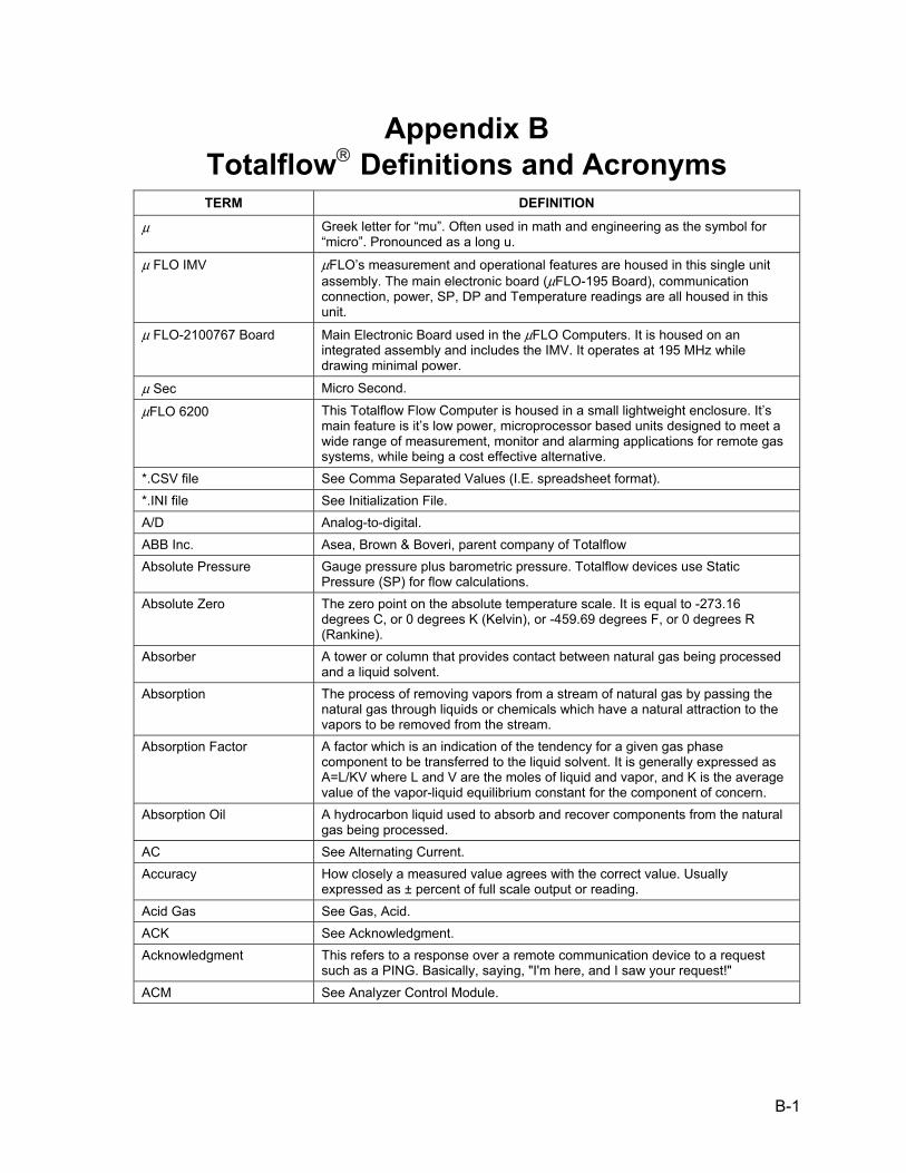
B-1
Appendix B Totalflow® Definitions and Acronyms TERM DEFINITION
µ Greek letter for “mu”. Often used in math and engineering as the symbol for “micro”. Pronounced as a long u.
µ FLO IMV µFLO’s measurement and operational features are housed in this single unit assembly. The main electronic board (µFLO-195 Board), communication connection, power, SP, DP and Temperature readings are all housed in this unit.
µ FLO-2100767 Board Main Electronic Board used in the µFLO Computers. It is housed on an integrated assembly and includes the IMV. It operates at 195 MHz while drawing minimal power.
µ Sec Micro Second.
µFLO 6200 This Totalflow Flow Computer is housed in a small lightweight enclosure. It’s main feature is it’s low power, microprocessor based units designed to meet a wide range of measurement, monitor and alarming applications for remote gas systems, while being a cost effective alternative.
*.CSV file See Comma Separated Values (I.E. spreadsheet format). *.INI file See Initialization File. A/D Analog-to-digital. ABB Inc. Asea, Brown & Boveri, parent company of Totalflow Absolute Pressure Gauge pressure plus barometric pressure. Totalflow devices use Static
Pressure (SP) for flow calculations. Absolute Zero The zero point on the absolute temperature scale. It is equal to -273.16
degrees C, or 0 degrees K (Kelvin), or -459.69 degrees F, or 0 degrees R (Rankine).
Absorber A tower or column that provides contact between natural gas being processed and a liquid solvent.
Absorption The process of removing vapors from a stream of natural gas by passing the natural gas through liquids or chemicals which have a natural attraction to the vapors to be removed from the stream.
Absorption Factor A factor which is an indication of the tendency for a given gas phase component to be transferred to the liquid solvent. It is generally expressed as A=L/KV where L and V are the moles of liquid and vapor, and K is the average value of the vapor-liquid equilibrium constant for the component of concern.
Absorption Oil A hydrocarbon liquid used to absorb and recover components from the natural gas being processed.
AC See Alternating Current. Accuracy How closely a measured value agrees with the correct value. Usually
expressed as ± percent of full scale output or reading. Acid Gas See Gas, Acid. ACK See Acknowledgment. Acknowledgment This refers to a response over a remote communication device to a request
such as a PING. Basically, saying, "I'm here, and I saw your request!" ACM See Analyzer Control Module.

B-2
TERM DEFINITION
Acoustics The degree of sound. The nature, cause, and phenomena of the vibrations of elastic bodies; which vibrations create compressional waves or wave fronts which are transmitted through various media, such as air, water, wood, steel, etc.
Active Analog Output Analog Output to a host providing power to the host. Active Mode An operational mode used by the LevelMaster for measuring dual float levels
by applying a signal to the primary windings, reading the voltage level on the secondary windings and using an algorithm to determine the oil and water levels.
Adapter A mechanism or device for attaching non-mating parts. ADC See Analog-to-Digital Converter. Address A unique memory designation for location of data or the identity of a peripheral
device; allows each device on a single communications line to respond to its own message.
Adiabatic Expansion The expansion of a gas, vapor, or liquid stream from a higher pressure to a lower pressure in which there is no heat transfer between the gas, vapor, or liquid and the surroundings.
Adsorption The process of removing natural gas liquids from a stream of natural gas by passing the natural gas through granular solids which have a natural attraction to the liquids to be removed from the stream.
Aerial A length of wire designed to transmit or receive radio waves. (See also Antenna)
Aerosol Liquids Minute liquid particles suspended in gas. Aerosols will behave like a fluid and can be transported by pipes and pumping. When aerosols contact each other they coalesce into droplets. Aerosols may be present in gas, or may be generated by glow shearing off the skim inside of a pipeline.
AGA American Gas Association. Trade group representing natural gas distributors and pipelines.
AGA-10 American Gas Association Report No. 10, Speed of Sound in Natural Gas and Other Related Hydrocarbon Gases. Method for calculation of the speed of sound in gases.
AGA-3 American Gas Association Report No. 3, Orifice Metering of Natural Gas. Method for calculating gas volume across an Orifice Plate. This method requires two pressure readings, Differential Pressure (DP) and Static Pressure (SP).
AGA-5 American Gas Association Report No. 5, Fuel Gas Energy Metering. Methods (Volume, Mass or Energy) for calculating BTUs without knowing the composition of the gas.
AGA-7 American Gas Association Report No. 7, Measurement of Gas by Turbine Meters. Method for calculating gas volume using a Pulse Meter. This method requires one pressure reading, Static Pressure (SP).
AGA-8 American Gas Association Report No. 8, Compressibility Factor of Natural Gas and Related Hydrocarbon Gases. Method for calculating the Super Compressibility Factor, Fpv.
AGA-9 American Gas Association Report No. 9, Measurement of Gas by Multipath Ultrasonic Meters. Method for calculating gas based on transit-times.
AGC Automatic Gain Control AH See Ampere-Hour. AI Analog Input AIU Analyzer Interface Unit.
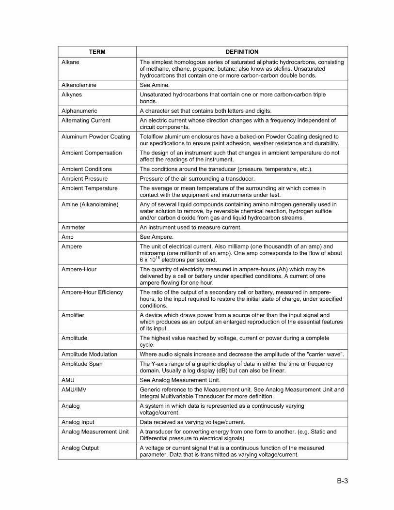
B-3
TERM DEFINITION
Alkane The simplest homologous series of saturated aliphatic hydrocarbons, consisting of methane, ethane, propane, butane; also know as olefins. Unsaturated hydrocarbons that contain one or more carbon-carbon double bonds.
Alkanolamine See Amine. Alkynes Unsaturated hydrocarbons that contain one or more carbon-carbon triple
bonds. Alphanumeric A character set that contains both letters and digits. Alternating Current An electric current whose direction changes with a frequency independent of
circuit components. Aluminum Powder Coating Totalflow aluminum enclosures have a baked-on Powder Coating designed to
our specifications to ensure paint adhesion, weather resistance and durability. Ambient Compensation The design of an instrument such that changes in ambient temperature do not
affect the readings of the instrument. Ambient Conditions The conditions around the transducer (pressure, temperature, etc.). Ambient Pressure Pressure of the air surrounding a transducer. Ambient Temperature The average or mean temperature of the surrounding air which comes in
contact with the equipment and instruments under test. Amine (Alkanolamine) Any of several liquid compounds containing amino nitrogen generally used in
water solution to remove, by reversible chemical reaction, hydrogen sulfide and/or carbon dioxide from gas and liquid hydrocarbon streams.
Ammeter An instrument used to measure current. Amp See Ampere. Ampere The unit of electrical current. Also milliamp (one thousandth of an amp) and
microamp (one millionth of an amp). One amp corresponds to the flow of about 6 x 10¹⁸ electrons per second.
Ampere-Hour The quantity of electricity measured in ampere-hours (Ah) which may be delivered by a cell or battery under specified conditions. A current of one ampere flowing for one hour.
Ampere-Hour Efficiency The ratio of the output of a secondary cell or battery, measured in ampere-hours, to the input required to restore the initial state of charge, under specified conditions.
Amplifier A device which draws power from a source other than the input signal and which produces as an output an enlarged reproduction of the essential features of its input.
Amplitude The highest value reached by voltage, current or power during a complete cycle.
Amplitude Modulation Where audio signals increase and decrease the amplitude of the "carrier wave". Amplitude Span The Y-axis range of a graphic display of data in either the time or frequency
domain. Usually a log display (dB) but can also be linear. AMU See Analog Measurement Unit. AMU/IMV Generic reference to the Measurement unit. See Analog Measurement Unit and
Integral Multivariable Transducer for more definition. Analog A system in which data is represented as a continuously varying
voltage/current. Analog Input Data received as varying voltage/current. Analog Measurement Unit A transducer for converting energy from one form to another. (e.g. Static and
Differential pressure to electrical signals) Analog Output A voltage or current signal that is a continuous function of the measured
parameter. Data that is transmitted as varying voltage/current.
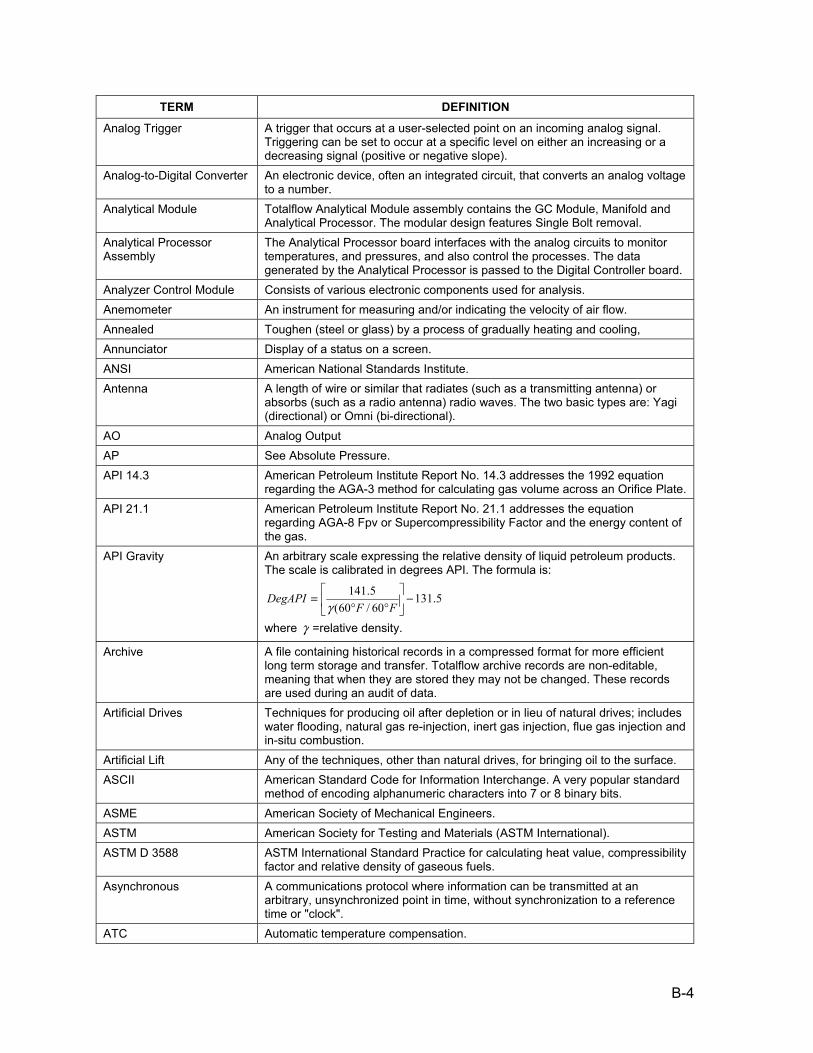
B-4
TERM DEFINITION
Analog Trigger A trigger that occurs at a user-selected point on an incoming analog signal. Triggering can be set to occur at a specific level on either an increasing or a decreasing signal (positive or negative slope).
Analog-to-Digital Converter An electronic device, often an integrated circuit, that converts an analog voltage to a number.
Analytical Module Totalflow Analytical Module assembly contains the GC Module, Manifold and Analytical Processor. The modular design features Single Bolt removal.
Analytical Processor Assembly
The Analytical Processor board interfaces with the analog circuits to monitor temperatures, and pressures, and also control the processes. The data generated by the Analytical Processor is passed to the Digital Controller board.
Analyzer Control Module Consists of various electronic components used for analysis. Anemometer An instrument for measuring and/or indicating the velocity of air flow. Annealed Toughen (steel or glass) by a process of gradually heating and cooling, Annunciator Display of a status on a screen. ANSI American National Standards Institute. Antenna A length of wire or similar that radiates (such as a transmitting antenna) or
absorbs (such as a radio antenna) radio waves. The two basic types are: Yagi (directional) or Omni (bi-directional).
AO Analog Output AP See Absolute Pressure. API 14.3 American Petroleum Institute Report No. 14.3 addresses the 1992 equation
regarding the AGA-3 method for calculating gas volume across an Orifice Plate. API 21.1 American Petroleum Institute Report No. 21.1 addresses the equation
regarding AGA-8 Fpv or Supercompressibility Factor and the energy content of the gas.
API Gravity An arbitrary scale expressing the relative density of liquid petroleum products. The scale is calibrated in degrees API. The formula is:
5.13160/60(5.141 −⎥
⎦
⎤⎢⎣
⎡°°
=FF
DegAPIγ
where γ =relative density.
Archive A file containing historical records in a compressed format for more efficient long term storage and transfer. Totalflow archive records are non-editable, meaning that when they are stored they may not be changed. These records are used during an audit of data.
Artificial Drives Techniques for producing oil after depletion or in lieu of natural drives; includes water flooding, natural gas re-injection, inert gas injection, flue gas injection and in-situ combustion.
Artificial Lift Any of the techniques, other than natural drives, for bringing oil to the surface. ASCII American Standard Code for Information Interchange. A very popular standard
method of encoding alphanumeric characters into 7 or 8 binary bits. ASME American Society of Mechanical Engineers. ASTM American Society for Testing and Materials (ASTM International). ASTM D 3588 ASTM International Standard Practice for calculating heat value, compressibility
factor and relative density of gaseous fuels. Asynchronous A communications protocol where information can be transmitted at an
arbitrary, unsynchronized point in time, without synchronization to a reference time or "clock".
ATC Automatic temperature compensation.

B-5
TERM DEFINITION
ATEX Term used for European Union’s New Approach Directive 94/9/EC which concerns equipment and protective systems intended for use in potentially explosive atomoshperes.
Atmosphere (one) A unit of pressure; the pressure that will support a column of mercury 760 mm high at 0 °C.
Atmospheric Pressure The pressure exerted on the earth by the earth’s atmosphere (air and water vapor). A pressure of 760 mm of mercury, 29.92 inches of mercury, or 14.696 pounds per square inch absolute is used as a (scientific) standard for some measurements. Atmospheric pressure may also refer to the absolute ambient pressure at any given location.
Audio Frequency Generally in the range 20 Hz to 20 KHz. Audit To examine or verify data for accuracy. Totalflow’s DB1 and DB2 records may
be edited to generate a more accurate representation of data information. Audit Trail Using the Long Term Archive files to justify changes made to records that more
accurately reflects the correct data. Peripheral information used to edit data is recorded without exception, to justify the accuracy of the edited data records.
Automatic Frequency Control
Similar to Automatic Fine Tune (AFT). A circuit that keeps a receiver in tune with the wanted transmission.
AWG American Wire Gage. AWG Acronym for American Wire Gauge. Back Pressure Pressure against which a fluid is flowing. May be composed of friction in pipes,
restrictions in pipes, valves, pressure in vessels to which fluid is flowing, hydrostatic head, or other resistance to fluid flow.
Backflush Technique used in chromatography to reverse direction of the flow after the lighter components have been measured, allowing the heavier components to remain in the column until measured, shortening the length of the column.
Background Acquisition Data is acquired by a DAQ system while another program or processing routine is running without apparent interruption.
Background Noise The total noise floor from all sources of interference in a measurement system, independent of the presence of a data signal.
Backup A system, device, file or facility that can be used as an alternative in case of a malfunction or loss of data.
Bandwidth The range of frequencies available for signaling; the difference between the highest and lowest frequencies of a band expressed in Hertz.
Bar Bar is equal to 1 atmosphere of pressure. I.e. .987 Standard atmospheric pressure or 14.5 lbs./psia.
Barometer An instrument which measures atmospheric pressure. Barrel A unit of liquid volume measurement in the petroleum industry that equals 42
U.S. gallons (.159 cubic meters) for petroleum or natural gas liquid products, measured at 60 degrees Fahrenheit and at an equilibrium vapor pressure.
Base Pressure The pressure used as a standard in determining gas volume. Volumes are measured at operating pressures and then corrected to base pressure volume. Base pressure is normally defined in any gas measurement contract. The standard value for natural gas in the United States is 14.73 psia, established by the American National Standards Institute as standard Z-132.1 in 1969.
Basic Sediment and Water Waste that collects in the bottom of vessels and tanks containing petroleum or petroleum products.
Battery Two or more electrochemical cells electrically interconnected in an appropriate series/parallel arrangement to provide the required operating voltage and current levels.

B-6
TERM DEFINITION
Baud Unit of signaling speed. The speed in baud is the number of discrete conditions or events per second. If each event represents only one bit condition, baud rate equals bits per second (bps).
Baud Rate Serial communications data transmission rate expressed in bits per second (b/s).
Bbl See Barrel. Bcf Abbreviation for one billion standard cubic feet or one thousand MMcf or one
million Mcf. BG Mix A liquefied hydrocarbon product composed primarily of butanes and natural
gasoline. Bias Term used when calibrating. Amounts to offset the actual measurement taken.
On a LevelMaster, it refers to adjusting the measurement of the float level to agree with a calibrated measurement. On an RTD (Resistant Thermal Detector), it refers to adjusting the measurement of the temperature to agree with a calibrated temperature. This figure maybe either a positive or negative figure.
BIAS Current A very low-level DC current generated by the panel meter and superimposed on the signal. This current may introduce a measurable offset across a very high source impedance.
Binary Number System based on the number 2. The binary digits are 0 and 1. Binary-Coded Decimal A code for representing decimal digits in a binary format. BIOS Basic Input/Output System. A program, usually stored in ROM, which provides
the fundamental services required for the operation of the computer. These services range from peripheral control to updating the time of day.
Bipolar A signal range that includes both positive and negative values. Bipolar Transistor The most common form of transistor. Bit Binary Digit - the smallest unit of binary data. One binary digit, either 0 or 1.
See also byte. Bits Per Second Unit of data transmission rate. Blue Dot Technology Technological changes to the DC and ACM Modules, decreasing noise by
changing ground. Allows amplification of the results, gains resolution. Board Common name used to identify the Main Electronic Board. Also called
Motherboard, Engine Card and Circuit Board. Boiling Point The temperature at which a substance in the liquid phase transforms to the
gaseous phase; commonly refers to the boiling point of water which is 100°C (212°F) at sea level.
Bounce Bouncing is the tendency of any two metal contacts in an electronic device to generate multiple signals as the contacts close or open. When you press a key on your computer keyboard, you expect a single contact to be recorded by your computer. In fact, however, there is an initial contact, a slight bounce or lightening up of the contact, then another contact as the bounce ends, yet another bounce back, and so forth. A similar effect takes place when a switch made using a metal contact is opened.
BP Mix A liquefied hydrocarbon product composed primarily of butanes and propane. BPS See Bits Per Second. Bridge Generally a short-circuit on a PC board caused by solder joining two adjacent
tracks. Bridge Resistance See Input impedance and Output impedance.

B-7
TERM DEFINITION
British Thermal Unit Energy required to raise one pound of water one degree Fahrenheit. One pound of water at 32 F° requires the transfer of 144 BTUs to freeze into solid ice.
Browser Software which formats Web pages for viewing; the Web client BS&W See Basic Sediment and Water. Btu See British Thermal Unit. Btu Factor A numerical representation of the heating value of natural gas which may be
calculated or presented to indicate varying relationships (e.g., the number of Btu contained in one standard cubic foot or the number of MMBtu contained in one Mcf of gas. The factor for a given relationship will vary depending upon whether the gas is “dry” or “saturated”.
Btu Method A method of allocating costs between different operations or between different products based upon the heat content of products produced in the various operations or of the various produced products.
Btu per Cubic Foot A measure of the heat available or released when one cubic foot of gas is burned.
Btu, Dry Heating value contained in cubic foot of natural gas measured and calculated free of moisture content. Contractually, dry may be defined as less than or equal to seven pounds of water per Mcf.
Btu, Saturated The number of Btu’s contained in a cubic foot of natural gas fully saturated with water under actual delivery pressure, temperature and gravity conditions. See BTU, DRY.
Btu/CV Used to express the heating content of gas. See British Thermal Units or Calorific Value.
BtuMMI Refers to the interface program or software that operates the Btu Analyzer. Buffer (1) A temporary storage device used to compensate for a difference in data rate
and data flow between two devices (typically a computer and a printer); also called a spooler; (2) An amplifier to increase the drive capability, current or distance, of an analog or digital signal.
Burst Pressure The maximum pressure applied to a transducer sensing element or case without causing leakage.
BUS A data path shared by many devices (e.g., multipoint line) with one or more conductors for transmitting signals, data, or power.
Bus Master A type of controller with the ability to read and write to devices on the computer bus.
Busbar A heavy, rigid conductor used for high voltage feeders. Butane (C4H10) A saturated hydrocarbon (Alkane) with four carbon atoms in it’s molecule
(C4H10). A gas at atmospheric pressure and normal temperature, but easily liquefied by pressure. Generally stored and delivered in liquefied form and used as a fuel in gaseous form, obtained by processing natural gas as produced and also from a process in petroleum refining. Contains approximately 3,260 Btu per cubic foot.
Butane, Normal see Normal Butane. Butylene (C4H8) A saturated hydrocarbon (Alkane) with four carbon atoms in it’s molecule
(C4H8). A gas at room temperature and pressure, but easily liquefied by lowering the temperature or raising the pressure. This gas is colorless, has a distinct odor, and is highly flammable. Although not naturally present in petroleum in high percentages, they can be produced from petrochemicals or by catalytic cracking of petroleum.
Byte A group of binary digits that combine to make a word. Generally 8 bits. Half byte is called a nibble. Large computers use 16 bits and 32 bits. Also used to denote the amount of memory required to store one byte of data.

B-8
TERM DEFINITION
C10H22 The molecular formula for Decane. C1H4 The molecular formula for Methane. C2H4 The molecular formula for Ethylene. C2H6 The molecular formula for Ethane. C3H6 The molecular formula for Propylene. C3H8 The molecular formula for Propane. C4H10 The molecular formula for Butane. C4H8C The molecular formula for Butylene. C5+ A standard abbreviation for Pentanes Plus (IC5, NC5 and C6+). C5H12 The molecular formula for Pentane. C6+ A standard abbreviation for Hexane Plus. C6H14 The molecular formula for Hexane. C7H16 The molecular formula for Heptane. C8H18 The molecular formula for Octane. C9H20 The molecular formula for Nonane. Cache Memory Fast memory used to improve the performance of a CPU. Instructions that will
soon be executed are placed in cache memory shortly before they are needed. This process speeds up the operation of the CPU.
Calibrate To ascertain, usually by comparison with a standard, the locations at which scale or chart graduations should be placed to correspond to a series of values of the quantity which the instrument is to measure, receive or transmit. Also, to adjust the output of a device, to bring it to a desired value, within a specified tolerance for a particular value of the input. Also, to ascertain the error in the output of a device by checking it against a standard.
Calorie The quantity of thermal energy required to raise one gram of water 1°C at 15°C. Calorimeter An apparatus which is used to determine the heating value of a combustible
material. Capacitor An electronic component that stores electrical charge. Capacity The total number of ampere-hours (or watt-hours) that can be withdrawn from a
cell/battery under specified conditions of discharge. Carbon Base of all hydrocarbons and is capable of combining with hydrogen in many
proportions, resulting in numberless hydrocarbon compounds. The carbon content of a hydrocarbon determines, to a degree, the hydrocarbon's burning characteristics and qualities.
Carbon Dioxide Colorless, odorless and slightly acid-tasting gas, consisting of one atom of carbon joined to two atoms of oxygen. C02. Produced by combustion or oxidation of materials containing carbon. Commonly referred to as dry ice when in its solid form.
Carrier Gas Totalflow recommends that Helium be used as a carrier gas. Carrier gas is used in the “Mobile Phase” of chromatography, pushing the sample gas through the columns (“Stationary Phase”). Because Helium has no heating value, it does not affect the Btu values.
Casinghead Gas Natural gas that is produced from oil wells along with crude oil. Catalyst A substance that speeds up a chemical reaction without being consumed itself
in the reaction. A substance that alters (usually increases) the rate at which a reaction occurs.
Catalytic The process of altering, accelerating or instigating a chemical reaction.
B-9
TERM DEFINITION
Cathode An electrode through which current leaves any nonmetallic conductor. An electrolytic cathode is an electrode at which positive ions are discharged, or negative ions are formed, or at which other reducing reactions occur. The negative electrode of a galvanic cell; of an electrolytic capacitor.
Cavitation The boiling of a liquid caused by a decrease in pressure rather than an increase in temperature.
CC Cubic Centimeters. Measurement unit for measuring volume or capacity in one hundredth of a meter.
CC Acronym for Cubic Centimeter. C-Code C language (IEC supported programming language) CCU See DosCCU, WINCCU, PCCU or WEBCCU. CCV See Closed Circuit Voltage. Cd Coefficient of Discharge factor. CE European Community Certification Bureau. Cell The basic electrochemical unit used to generate or store electrical energy. Celsius (centigrade) A temperature scale defined by 0°C at the ice point and 100°C at boiling point
of water at sea level. CENELEC European Committee for Electro-technical Standardization. Also known as the
European Standards Organization. Centimeter Acronym c. Metric measurement equal to .3937 inch. Central Processing Unit The central part of a computer system that performs operations on data. In a
personal computer the CPU is typically a single microprocessor integrated circuit.
Ceramic Insulation High-temperature compositions of metal oxides used to insulate a pair of thermocouple wires The most common are Alumina (Al2O3), Beryllia (BeO), and Magnesia (MgO). Their application depends upon temperature and type of thermocouple. High-purity alumina is required for platinum alloy thermocouples. Ceramic insulators are available as single and multihole tubes or as beads.
Certification The process of submitting equipment to specific tests to determine that the equipment meets the specifications or safety standards.
Cf A standard abbreviation for Cubic foot. CFG Configuration File. When saving new configuration files, the file is saved as a
*.cfg file. CFM The volumetric flow rate of a liquid or gas in cubic feet per minute. Character A letter, digit or other symbol that is used as the representation of data. A
connected sequence of characters is called a character string. Characteristics Detailed information pertaining to it’s description. The XFC stores this
information in the PROM chip. A feature or quality that makes somebody or something recognizable.
Charge The conversion of electrical energy, provided in the form of a current from an external source, into chemical energy within a cell or battery.
Chip Another name for integrated circuit or the piece of silicon on which semiconductors are created.
Chromatograph An instrument used in chemical analysis, to determine the make-up of various substances, and often used to determine the Btu content of natural gas. Chromatography- A method of separating gas compounds by allowing it to seep through an adsorbent so that each compound is adsorbed in a separate layer.

B-10
TERM DEFINITION
CIM Communication Interface Module. Totalflow’s version is called TFIO Communication Interface Module.
Circuit 1. The complete path between two terminals over which one-way or two-way communications may be provided. 2. An electronic path between two or more points, capable of providing a number of channels. 3. A number of conductors connected together for the purpose of carrying an electrical current. 4. An electronic closed-loop path among two or more points used for signal transfer. 5. A number of electrical components, such as resistors, inductances, capacitors, transistors, and power sources connected together in one or more closed loops.
Circuit board Sometimes abbreviated PCB. Printed circuit boards are also called cards. A thin plate on which chips and other electronic components are placed. They fall into the following categories: Motherboard: Typically, the mother board contains the CPU, memory and basic controllers for the system. Sometimes call the system board or main board. Expansion board: Any board that plugs into one of the computer's expansion slots, including controller boards, LAN cards, and video adapters. Daughter Card: Any board that attaches directly to another board. Controller board: A special type of expansion board that contains a controller for a peripheral device. Network Interface Card (NIC): An expansion board that enables a PC to be connected to a local-area network (LAN). Video Adapter: An expansion board that contains a controller for a graphics monitor.
Class 1, Division 1 Class 1 refers to the presence of flammable gases, vapors or liquids. Division 1 indicates an area where ignitable concentrations of flammable gases, vapors or liquids can exist all of the time or some of the time under normal operating conditions.
Class 1, Division 2 Class 1 refers to the presence of flammable gases, vapors or liquids. Division 2 indicates an area where ignitable concentrations of flammable gases, vapors or liquids are not likely to exist under normal operating conditions.
Class 1, Zone 0 Class 1 refers to the presence of flammable gases, vapors or liquids. Zone 0 refers to a place in which an explosive atmosphere consisting of a mixture with air of flammable substances in the form of gas, vapor or mist is present continuously or for long periods or frequently.
Class 1, Zone 1 Class 1 refers to the presence of flammable gases, vapors or liquids. Zone 1 refers to a place in which an explosive atmosphere consisting of a mixture with air of flammable substances in the form of gas, vapor or mist is likely to occur in normal operation occasionally.
Class 1, Zone 2 Class 1 refers to the presence of flammable gases, vapors or liquids. Zone 2 refers to a place in which an explosive atmosphere consisting of a mixture with air of flammable substances in the form of gas, vapor or mist is not likely to occur in normal operation.
Clean Gas Gas that has no particles larger than one micron and no more than one milligram of solids per cubic meter.
Clear To restore a device to a prescribed initial state, usually the zero state. Clock The source(s) of timing signals for sequencing electronic events (e.g.
synchronous data transfer). Closed Circuit Voltage The difference in potential between the terminals of a cell/battery when it is
discharging (on- load condition). CM Acronym for Cubic Meter. Cm Acronym for Centimeter. CMM Acronym for Cubic Meter per Minute.

B-11
TERM DEFINITION
CMOS See Complimentary Metal-Oxide-Semiconductor. CNG See Compressed Natural Gas CO2 A standard abbreviation for Carbon Dioxide. Coalbed Methane A methane-rich, sulfur-free natural gas contained within underground coal
beds. Coefficient of expansion The ratio of the change in length or volume of a body to the original length or
volume for a unit change in temperature. Coil A conductor wound in a series of turns. Cold Start A rebooting technique which will clear all operational errors, loose all data files,
but will not damage configuration files if stored on the SDRIVE. Cold Weather Enclosure Totalflow insulated and heated enclosure designed to house either the
NGC8200 or Btu 8000/8100 Chromatographs in inclement climates. Collector The semiconductor region in a bipolar junction transistor through which a flow
of charge carriers leaves the base region. Column Hardware component used in gas chromatography to separate components
into measurable units. Combustible Classification of liquid substances that will burn on the basis of flash points. A
combustible liquid means any liquid having a flash point at or above 37.8°C (100°F) but below 93.3°C (200°F), except any mixture having components with flash points of 93.3°C (200°F) or higher, the total of which makes up 99 percent or more of the total volume of the mixture.
Comma Separated Values These file types are importable records used by spreadsheet programs to display and manipulate data.
Communication Transmission and reception of data among data processing equipment and related peripherals.
Communication Port Comm. Port (abbreviation) refers to the host computer's physical communication's port being used to communicate with the equipment. Used by Totalflow when discussing local or remote communication with various equipment including the XFC, FCU, XRC, RTU and LevelMaster etc.
Compensation An addition of specific materials or devices to counteract a known error. Complimentary Metal-Oxide-Semiconductor
Family of logic devices that uses p-type and n-type channel devices on the same integrated circuit. It has the advantage of offering medium speed and very low power requirements.
Component (1) A small object or program that performs a specific function and is designed in such a way to easily operate with other components and applications. Increasingly, the term is being used interchangeably with applet. (2) A part of a device.
Compressed Gas A gas or mixture of gases having, in a container an absolute pressure exceeding 40 psi at 21.1°C (70°F). A gas or mixture having in a container, an absolute pressure exceeding 104 psi at 54.4°C (130°F) regardless of the pressure at (21.1°C (70°F). A liquid having a vapor pressure exceeding 40 psi at 37.8°C (70°F) as determined by ASTM D-323-72.
Compressed Natural Gas Natural gas in high-pressure surface containers that is highly compressed (though not to the point of liquefaction). CNG is used extensively as a transportation fuel for automobiles, trucks and buses in some parts of the world. Small amounts of natural gas are also transported overland in high-pressure containers.
Compressibility The property of a material which permits it to decrease in volume when subjected to an increase in pressure. In gas-measurement usage, the compressibility factor "Z" is the deviation from the ideal Boyle and Charles' law behavior. See SUPERCOMPRESSIBILITY FACTOR.

B-12
TERM DEFINITION
Compressibility Factor See Supercompressibility Factor. Compressibility Factor A factor usually expressed as “z” which gives the ratio of the actual volume of
gas at a given temperature and pressure to the volume of gas when calculated by the ideal gas law without any consideration of the compressibility factor.
Concentration Amount of solute per unit volume or mass of solvent or of solution. Concurrent Performing more than one task at a time. Condensate 1) The liquid formed by the condensation of a vapor or gas; specifically, the
hydrocarbon liquid separated from natural gas because of changes in temperature and pressure when the gas from the reservoir was delivered to the surface separators. 2) A term used to describe light liquid hydrocarbons separated from crude oil after production and sold separately.
Condensation Liquefaction of vapor. Condensed Phases The liquid and solid phases; phases in which particles interact strongly. Condensed States The solid and liquid states. Conduction The conveying of electrical energy or heat through or by means of a conductor. Configuration No. The Configuration number is a suffix of the serial number which defines the
characteristics of the unit. Console Mode A local user interface typically used with custom applications that are not
supported through any other mechanism. Also referred to as Printer Console Mode.
Contact Current carrying part of a switch, relay or connector. Conversion Time The time required, in an analog input or output system, from the moment a
channel is interrogated (such as with a read instruction) to the moment that accurate data is available. This could include switching time, settling time, acquisition time, A/D conversion time, etc.
Coprocessor Another computer processor unit that operates in conjunction with the standard CPU. Can be used to enhance execution speed. For example, the 8087 is designed to perform floating point arithmetic.
COR See Corrected Runtime. Corrected Runtime Correction to signal made to decrease/increase “ZERO phase” and eliminate
the shift between RT and COR for increased accuracy. Cos See Cosine. Cosine The sine of the complement of an arc or angle. Counterclockwise Movement in the direct opposite to the rotation of the hands of a clock. Counts The number of time intervals counted by the dual-slope A/D converter and
displayed as the reading of the panel meter, before addition of the decimal point.
CPS Cycles per second; the rate or number of periodic events in one second, expressed in Hertz (Hz).
CPU See Central Processing Unit. CPUC California Public Utilities Commission CRC See Cyclic Redundancy Check. Cryogenic Plant A gas processing plant which is capable of producing natural gas liquids
products, including ethane, at very low operating temperatures. CSA CSA International: Formerly Canadian Standards Association. Canadian
certification agency. CTS Communication abbreviation for Clear To Send. Cubic Three-dimensional shape with six equal sides. Used in measuring volume.

B-13
TERM DEFINITION
Cubic Centimeter Acronym CC. Metric volume equal to a 1 Centimeter to the 3rd power. Cubic Foot The most common unit of measurement of gas volume in the US. It is the
amount of gas required to fill a volume of one cubic foot under stated conditions of temperature, pressure, and water vapor.
Cubic Foot Metered The quantity of gas that occupies one cubic foot under pressure and temperature conditions in the meter.
Cubic Foot, Standard That quantity of gas which under a pressure of 14.73 psia and at a temperature of 60 degrees occupies a volume of one cubic foot without adjustment for water vapor content.
Cubic Meter Acronym CM. Metric volume equal to 35.31467 Cubic Feet. Cubic Meter Per Minute Acronym CMM. Metric flow rate equal to 35.31467 Cubic Feet per Minute. Cumulative Capacity The total number of ampere-hours (or watt hours) that can be withdrawn from a
cell/battery under specified conditions of discharge over a predetermined number of cycles or the cycle life.
Current Current is measured in amps (milliamps and microamps). It is the passage of electrons. Conventional current flows from positive to negative. Electrons flow from negative to positive - called "electron flow".
Cursor Dots used to indicate the location of the next character or symbol to be entered. Custody Transfer The legal and commercial transfer of a commodity such as natural gas, LNG,
etc. from one party to another. Custody Transfer Transaction
The Custody Transfer Transaction is the hand-off of the physical commodity from one operator to another.
Cut-Off Voltage The cell/battery voltage at which the discharge is terminated. CV Calorific Value. European value of heating content. CWE Cold Weather Enclosure. Cycle One complete sequence of events. One complete alteration of an AC current or
Volt. The discharge and subsequent charge of a rechargeable cell/battery is called a cycle.
Cycle Life The number of cycles under specified conditions which were available from a rechargeable cell/battery before it fails to meet specified criteria as to performance.
Cycle Time The time usually expressed in seconds for a controller to complete one on/off cycle.
Cyclic Redundancy Check An ongoing verification of the validity of transmitted and received data providing assurance that the message conforms to a pre-agreed upon convention of communications.
D/A See Digital-to-analog. D/I See Digital Input. D/O See Digital Output. DAC See Digital to Analog Converter. DACU Data Acquisition Control Unit. Data Acquisition Gathering information from sources such as sensors and AMUs in an accurate,
timely and organized manner. Modern systems convert this information to digital data, which can be stored and processed by a computer.
Data Collect Physically, locally or remotely, retrieving data stored with a Totalflow unit. This data is typically stored in records located in a data base format.
DB See Decibel. DB1 Acronym for Data Base 1. This refers to the previous data base structure used
to store data in Totalflow products.

B-14
TERM DEFINITION
DB2 Acronym for Data Base 2. This refers to the current data base structure used to store data in Totalflow products.
DC See Direct Current DCD Communication abbreviation for Data Carrier Detect DCS/PLC Distribution Control System/Programmable Logic Controller DDE See Digital Data Exchange. Also called Dynamic Data Exchange. May refer to
Totalflow’s DDE Server TDS32. Dead Weight Tester Portable pressure tester used to check calibration and to calibrate AMU’s
utilizing a system of calibrated weights. De-bounce De-bouncing is any kind of hardware device or software that ensures that only
a single signal will be acted upon for a single opening or closing of a contact. When you press a key on your computer keyboard, you expect a single contact to be recorded by your computer. In fact, however, there is an initial contact, a slight bounce or lightening up of the contact, then another contact as the bounce ends, yet another bounce back, and so forth. A similar effect takes place when a switch made using a metal contact is opened. The usual solution is a de-bouncing device or software that ensures that only one digital signal can be registered within the space of a given time (usually milliseconds)
Decane (C10H22) A hydrocarbon (Alkane) flammable colorless liquid with ten carbon atoms. Decibel A logarithmic measure of the ratio of two signal levels. A practical unit of gain. Decimal A numbering system based on 10. Default A value assigned or an action taken automatically unless another is specified. Degree An incremental value in the temperature scale, i.e., there are 100 degrees
between the ice point and the boiling point of water in the Celsius scale and 180°F between the same two points in the Fahrenheit scale.
Delivery Point Point at which gas leaves a transporter's system completing a sale or transportation service transaction between the pipeline company and a sale or transportation service customer.
Demand Day That 24-hour period specified by a supplier-user contract for purposes of determining the purchaser's daily quantity of gas used (e.g., 8 AM to 8 AM, etc.). This term is primarily used in pipeline-distribution company agreements. It is similar to, and usually coincides with, the distribution company "Contract Day".
Demand Load The rate of flow of gas required by a consumer or a group of consumers, often an average over a specified short time interval (cf/hr or Mcf/hr). Demand is the cause; load is the effect.
Demand Meters A device which indicates or records the instantaneous, maximum or integrated (over a specified period) demand.
Demand, Average The demand on a system or any of its parts over an interval of time, determined by dividing the total volume in therms by the number of units of time in the interval.
Density Mass per unit Volume: D=MV Desaturization Doesn’t cause the composition of the gas to change, enabling a more
representative sample of gas. Detector Bead See Thermal Conductivity Detector. Deviation The difference between the value of the controlled variable and the value at
which it is being controlled. Dew Point The temperature at any given pressure at which liquid initially condenses from
a gas or vapor. It is specifically applied to the temperature at which water vapor starts to condense from a gas mixture (water dew point) or at which hydrocarbons start to condense (hydrocarbon dew point).

B-15
TERM DEFINITION
Dewar A glass or metal container made like a vacuum bottle that is used especially for storing liquefied gases. Also called “Dewar flask”.
DG Display Group. When display group files are created Diaphragm A bellows inside a displacement type gas meter. Also, a membrane separating
two different pressure areas within a control valve or regulator. Differential For an on/off controller, it refers to the temperature difference between the
temperature at which the controller turns heat off and the temperature at which the heat is turned back on. It is expressed in degrees.
Differential Input A signal-input circuit where SIG LO and SIG HI are electrically floating with respect to ANALOG GND (METER GND, which is normally tied to DIG GND). This allows the measurement of the voltage difference between two signals tied to the same ground and provides superior common-mode noise rejection.
Differential Pressure The pressure difference between two points in a system. For example, the difference in pressure between the upstream and downstream taps of an orifice plate, used to measure volume passing through the orifice.
Digit A measure of the display span of a panel meter. By convention, a full digit can assume any value from 0 through 9, a 1/2-digit will display a 1 and overload at 2, a 3/4-digit will display digits up to 3 and overload at 4, etc. For example, a meter with a display span of ±3999 counts is said to be a 3-3/4 digit meter.
Digital A signal which has distinct states, either on or off (0 or 1). Digital computers process data as binary information having either true of false states.
Digital Controller Assembly The Digital Controller Assembly contains the Digital Electronic Board, Mounting Assembly and optionally a VGA Display. The Digital Controller board provides control parameters to the Analytical Processor board, stores and processes the data sent from the Analytical Processor board. The Digital Controller also processes communication with other devices.
Digital Data Information transmitted in a coded form (from a computer), represented by discrete signal elements.
Digital Data Exchange or Dynamic Data Exchange
A Microsoft data exchange format generally used to transfer data from one program to another. It is a very simple format to use and Totalflow customers often use TDS to acquire data from Totalflow devices and then transfer the data to an Excel spreadsheet using DDE. The Totalflow Driver, TDS32, supports DDE and its network version, NetDDE.
Digital Electronics The branch of electronics dealing with information in binary form. Digital Input Refers to the signal received in binary format. Digital Output Refers to the signal emitted in binary format. An output signal which represents
the size of an input in the form of a series of discrete quantities. Digital to Analog Conversion
The process of translating discrete data into a continuously varying signal. Common uses are to present the output of a digital computer as a graphic display or as a test stimulus.
Digital-to-Analog Converter An electronic device, often an integrated circuit, that converts a digital number into a corresponding analog voltage or current.
DIN Deutsches Institut für Normung. German Institute for Standardization set of standards recognized throughout the world.
DIN Rail Rail on which modules are mounted. Allows modules to snap on and slide right and left.
Diode A semiconductor that allows current to flow in one direction only. DIP Switches A bank of switches typically used in setting the hardware configuration and
base address of an option card.

B-16
TERM DEFINITION
Direct Current A current that does not change in direction and is substantially constant in value.
Direct Memory Access A method by which information can be transferred from the computer memory to a device on the bus without using the processor.
Discharge The conversion of chemical energy of a cell/battery into electrical energy and withdrawal of the electrical energy into a load.
Discharge Rate The rate, usually expressed in amperes, at which electrical current is taken from the cell/battery.
Discrete Manifold Also called Tubing Manifold. Used in instances when the XFC is not mounted directly on the Orifice, usually pipe mount or wall mount.
Distillates The distillate or middle range of petroleum liquids produced during the processing of crude oil. Products include diesel fuel, heating oil, kerosene and turbine fuel for airplanes.
Distillation The first stage in the refining process in which crude oil is heated and unfinished petroleum products are initially separated.
Distribution The act or process of distributing gas from the city gas or plant that portion of utility plant used for the purpose of delivering gas from the city gate or plant to the consumers, or to expenses relating to the operating and maintenance of distribution plant.
Distribution Company Gas Company which obtains the major portion of its gas operating revenues from the operation of a retail gas distribution system, and which operates no transmission system other than incidental connections within its own system or to the system of another company. For purposes of A.G.A. statistics, a distribution company obtains at least 90 percent of its gas operating revenues from sales to ultimate customers, and classifies at least 90 percent of mains (other than service pipe) as distribution. Compare INTEGRATED COMPANY; TRANSMISSION COMPANY, GAS.
Dkt Abbreviation for Decatherm, equivalent to one MMBtu. DN Inside diameter standard. DOS Disk Operating System. DOS CCU Refers to the DOS version of the Calibration and Collection Unit. Also known as
FS/2, hand held or Dog Bone. DOT Matrix A group of dots/pixels forming a character or symbol, usually five dots across
and seven dots down. DOT/Pixel An active element that forms a character or symbol when combined in a matrix. Download This refers to a Totalflow procedure in which any file(s) located on a laptop PC
or storage device, may be copied to the on-board memory of a Totalflow Host device for purposes of restoring, configuration or repair.
Downstream The oil industry term used to refer to all petroleum activities from the processing of refining crude oil into petroleum products to the distribution, marketing, and shipping of the products. Also see Upstream.
Downstream Pipeline The pipeline receiving natural gas at a pipeline inter-connect point. DP See Differential Pressure. DRAM See Dynamic Random Access memory. Drift A change of a reading or a set point value over long periods due to several
factors including change in ambient temperature, time, and line voltage. Drip Gasoline Hydrocarbon liquid that separates in a pipeline transporting gas from the well
casing, lease separation, or other facilities and drains into equipment from which the liquid can be removed.
Driver (Hardware) An electronic circuit that provides input to another electronic circuit.

B-17
TERM DEFINITION
Driver (Software) A program that exercises a system or system component by simulating the activity of a higher level component.
Drivers Software that controls a specific hardware device, such as interface boards, PLCs, RTUs, and other I/O devices.
Droplet Liquids Large liquid particles Dry Contact Contacts which neither break nor make a circuit. 0 Ohms. Dry Gas Has no more than seven pounds of water per million cubic feet of gas. Gas has
less than 0.1 PPM of liquid at the coldest ambient condition expected at the coldest point in the system. The liquid can be water, oil, synthetic lubrication, glycol, condensed sample or any other non vapor contaminate.
DSP Digital Signal Processor. Dual Element Sensor A sensor assembly with two independent sensing elements. Dual-Access Memory Memory that can be sequentially accessed by more than one controller or
processor but not simultaneously accessed. Also known as shared memory. Duplex The ability to both send and receive data simultaneously over the same
communications line. Duplex Wire A pair of wires insulated from each other and with an outer jacket of insulation
around the inner insulated pair. Duty Cycle The total time to one on/off cycle. Usually refers to the on/off cycle time of a
temperature controller. DVI The Port Manager and communication engine of the iVision SCADA System.
This software can multiplex among several communication formats and thus supporting several vendor’s equipment over a single radio frequency. It “pushes” new data to the iVision database, saving time and network resources by not transmitting redundant data. The DVI includes the Totalflow WinCPC code and thus supports all Totalflow software and functions – including WinCCU, TDS, PCCU, Report by exception, cryout, etc.
Dynamic Random Access memory
This is the most common form of computer memory It needs to be continually refreshed in order to properly hold data, thus the term "dynamic."
E2Prom See Electrically Erasable Programmable Read-Only Memory. Also called EEPROM.
Earth Can mean a connection to the earth itself or the negative lead to the chassis or any point to zero voltage.
EC European Community. Echo To reflect received data to the sender. i.e. depressed on a keyboard are usually
echoed as characters displayed on the screen. Edit Making changes to information, data or configuration files. EEPROM See Electrically Erasable Programmable Read-Only Memory. The PROM can
be erased by electricity. EFI Electromechanical Frequency Interface. EFM See Electronic Flow Measurement. EFR Enhance Feature Release. Electrical Interference Electrical noise induced upon the signal wires that obscures the wanted
information signal. Electrically Erasable Programmable Read-Only Memory
ROM that can be erased with an electrical signal and reprogrammed. Also referred to as the S Drive. It is a persistent drive that will not loose it’s memory unless manually reprogrammed. Also called E2Prom. Totalflow’s XFC and XRC have a Serial EEPROM on board, which generally holds registry, application configuration and warranty information (non-volatile).
Electrode The site, area, or location at which electrochemical processes take place.

B-18
TERM DEFINITION
Electromagnetic Compatibility
Term used for European Union’s New Approach Directive 89/336/EEC which means the device or system is able to function in its electromagnetic environment without introducing intolerable electromagnetic disturbances to anything in that environment.
Electromagnetic Interference
Any electromagnetic disturbance that interrupts, obstructs, or otherwise degrades or limits the effective performance of electronics/electrical equipment. It can be induced intentionally, as in some forms of electronic warfare, or unintentionally, as a result of spurious emissions and responses, intermodulation products, and the like.
Electronic Flow Measurement
Historically, flow measurement was tracked using a chart recording technology. Developments in the field of electronics allowed for electronic measurement devices to overtake the chart recording market. This field continues to develop into peripheral markets, making the “Flow Meter” a valuable asset with multi-tasking “Control” capabilities. Totalflow’s answer to this developing market is the XSeries equipment.
EMC See Electromagnetic Compatibility EMI See Electromagnetic Interference. Emitter One terminal of a transistor. EN Euro Norm (European Standard) Enagas Spain’s Certification Board Encoder A device that converts linear or rotary displacement into digital or pulse signals.
The most popular type of encoder is the optical encoder, which uses a rotating disk with alternating opaque areas, a light source, and a photodetector.
Environmental Conditions All conditions in which a transducer may be exposed during shipping, storage, handling, and operation.
EP Mix A liquefiable hydrocarbon product consisting primarily of ethane and propane. EPROM See Erasable Programmable Read-Only Memory. The PROM can be erased
by ultraviolet light or electricity. Erasable Programmable Read-Only Memory
ROM that can be erased using Ultraviolet Light. The EPROM maybe re-programmed by removing the EPROM from the circuit and using special equipment to write to it.
Ethane (C2H6) A colorless hydrocarbon gas of slight odor having a gross heating value of 1,773 Btu per cubic foot and a specific gravity of 1.0488. It is a normal constituent of natural gas.
Ethylene (C2H4) A colorless unsaturated hydrocarbon gas of slight odor having a gross heating value of 1,604 Btu per cubic foot and a specific gravity of 0.9740. It is usually present in manufactured gas, constituting one of its elements and is very flammable.
EU European Union. Formerly known as the European Community (EC). Members of this union are replacing individual national regulations of member countries with a series of Directives. These Directives are legislative instruments which oblige member states to introduce them into their existing laws. These directives harmonize a variety of existing practices, preserve the different legal traditions and settle constraints for further developments.
Event Important incident: an occurrence, especially one that is particularly significant. Event File Stored records specifying a notable change. The XFC stores up to 200 records,
containing: Time, Day, Description, Old Value, New Value. Events Signals or interrupts generated by a device to notify another device of an
asynchronous event. The contents of events are device-dependent. Ex Potential Explosive. EXIMV Explosion Proof Integral Multivariable Transducer.

B-19
TERM DEFINITION
Expansion Board A plug-in circuit board that adds features or capabilities beyond those basic to a computer, such as a data acquisition system expansion board.
Expansion Factor Correction factor for the change in density between two pressure measurement areas in a constricted flow.
Expansion Slots The spaces provided in a computer for expansion boards than enhance the basic operation of the computer.
Explosion-proof Enclosure Explosion Proof Enclosure for Class 1 Division 1 locations. An enclosure that can withstand an explosion of gases within it and prevent the explosion of gases surrounding it due to sparks, flashes or the explosion of the container itself, and maintain an external temperature which will not ignite the surrounding gases.
Extended Binary Coded Decimal Interchange Code
EBCDIC. An eight-bit character code used primarily in IBM equipment. The code allows for 256 different bit patterns.
External Multivariable Transducer
Multivariable Transducer located outside of the Flow Computer enclosure. Used in multi-tube configurations and on systems where the actual Flow Computer is located at a distance from the flowing tube.
External Transducer DP/SP Transducer located outside the enclosure. All electronics are located inside the enclosure and communicate via a ribbon cable.
F.O.B. Abbreviation of free on board with the cost of delivery to a port and loading onto a ship included.
Fa Orifice Thermal Expansion factor. Fahrenheit A temperature scale defined by 32° at the ice point and 212° at the boiling point
of water at sea level. Faux Full Well Stream Factor. Fb Basic Orifice factor. FBD Function Block Diagram (IEC supported programming language) FCC Federal Communications Commission. FCU Flow computer unit Feed Points Connections between gas feeder lines and distribution networks. Feedback Occurs when some or all of the output of the device (such as an amplifier) is
taken back to the input. This may be accidental (such as the acoustic feedback from a speaker to microphone) or intentional , to reduce distortion.
Feeder (Main) A gas main or supply line that delivers gas from a city gate station or other source of supply to the distribution networks.
Feed-Through Assembly The Feed-Through Assembly also serves as the connection for sample streams, carrier gas and calibration streams, and contains the vents for sample and column gases.
FET Field-effect transistor. Transistor with electric field controlling output: a transistor, with three or more electrodes, in which the output current is controlled by a variable electric field.
Fg Specific Gravity factor. Field Pressure The pressure of natural gas as it is found in the underground formations from
which it is produced. File A set of related records or data treated as a unit. Film Liquids Aerosols liquids who have contacted each other and become adhered to the
inside of the pipeline. Firmware A computer program or software stored permanently in PROM or ROM or semi-
permanently in EPROM. Firmware Version This refers to the version of firmware contained in the equipment.

B-20
TERM DEFINITION
Fixed-Point A format for processing or storing numbers as digital integers. Flag Any of various types of indicators used for identification of a condition or event;
for example, a character that signals the termination of a transmission. Flameproof Enclosure “d” Enclosure which can withstand the pressure developed during an internal
explosion of an explosive mixture, and which prevents the transmission of the explosion to the explosive atmosphere surrounding the enclosure.
Flammable A liquid as defined by NFPD and DOT as having a flash point below 37.8°C (100°F).
Flange For pipe, a metal collar drilled with bolt holes and attached to the pipe with its flat surface at right angles to the pipe axis so that it can be securely bolted to a mating flange on a valve, another pipe section, etc.
FLASH Re-programmable memory onboard an XFC/XRC, similar to an EPROM, except that it can be programmed while in circuit using a Boot Loader Program to write to it. Generally used for the operating system and application code space (non-volatile).
Flash ADC An Analog to Digital Converter whose output code is determined in a single step by a bank of comparators and encoding logic.
Flash Point The temperature at which a liquid will yield enough flammable vapor to ignite. There are various recognized industrial testing methods; therefore the method used must be stated.
Flash Vapors Gas vapors released from a stream of natural gas liquids as a result of an increase in temperature or a decrease in pressure.
Flow Travel of liquids or gases in response to a force (i.e. pressure or gravity). Flow Computer, XSeries A device placed on location to measure SP, DP and temperature (to calculate
flow) of gases or liquids being transferred, for remote unattended operation. Flow Formulas In the gas industry, formulas used to determine gas flow rates or pressure
drops in pipelines, regulators, valves, meters, etc. Flow Rate Actual speed or velocity of fluid movement . Flowmeter A device used for measuring the flow or quantity of a moving fluid. Fluids Substances that flow freely; gases and liquids. FM Factory Mutual Research Corporation. An organization which sets industrial
safety standards. FM Approved An instrument that meets a specific set of specifications established by Factory
Mutual Research Corporation. Font The style of lettering used to display information. Footprint The surface space required for an object. Fpb Pressure Base factor. FPM Flow velocity in feet per minute. FPS Flow velocity in feet per second. Fpv See Supercompressibility Factor. Fr Reynolds Number factor. Fractionation The process of separating a steam of natural gas liquids into its separate
components. Freezing Point The temperature at which the substance goes from the liquid phase to the solid
phase. Frequency The number of cycles per second for any periodic waveform - measured in
cycles per second - now called Hertz. The number of repeating corresponding points on a wave that pass a given observation point per unit time.

B-21
TERM DEFINITION
Frequency Modulation Modulation where the frequency of the sinewave carrier alters with the amplitude of the modulating signal.
Frequency Output An output in the form of frequency which varies as a function of the applied input.
FRP Fiberglass Reinforced Polyurethane. A non-flexible material used for LevelMaster sensors.
FS/2 Ruggadized handheld computer device for programming and collecting data from an XFC. Also referred to a Husky or Dog Bone.
FT3 A standard abbreviation for Cubic Foot. Ftb Temperature Base factor. Ftf Flowing Temperature factor. Fuel Oils The heavy distillates from the oil refining process that are used primarily for
heating, for fueling industrial processes, for fueling locomotives and ships, and for fueling power generation systems.
Full Bridge Wheatstone bridge configuration utilizing four active elements or strain gauges. Full Duplex Simultaneous, two-way (transmit and receive), transmission. Function A set of software instructions executed by a single line of code that may have
input and/or output parameters and returns a value when executed. Fuse A short length of wire that will easily burn out when excessive current flows. Fw Water Vapor factor. G The symbol used for giga or gigabyte. Gain The factor by which a signal is amplified, sometimes expressed in dB. Gain Accuracy A measure of deviation of the gain of an amplifier from the ideal gain. Gal An abbreviation for one gallon. Gas That state of matter which has neither independent shape nor volume. It
expands to fill the entire container in which it is held. It is one of the three forms of matter, the other two being solid and liquid.
Gas Chromatograph An analytical instrument that separates mixtures of gas into identifiable components by means of chromatography.
Gas Chromatograph Module
Software module used in conjunction with PCCU32 and WINCCU to interact with Btu Chromatograph equipment and software.
Gas Chromatograph Module Coefficient
A co-efficient generated by the factory allowing user to start calibration on location without having a calibration gas available.
Gas Chromatography Preferred method for determining the Btu value of natural gas. Gas Field A district or area from which natural gas is produced. Gas Injection An enhanced recovery technique in which natural gas is injected under
pressure into a producing reservoir through an injection well to drive oil to the well bore and the surface.
Gas Processing The separation of components by absorption, adsorption, refrigeration or cryogenics from a stream of natural gas for the purpose of making salable liquid products and for treating the residue gas to meet required specifications.
Gas, Acid The hydrogen sulfide and/or carbon dioxide contained in, or extracted from, gas or other streams.
Gas, Associated Gas produced in association with oil, or from a gas cap overlying and in contact with the crude oil in the reservoir. In general, most states restrict associated gas production since its indiscriminate production could reduce the ultimate oil recovery. Also, since some wells producing associated gas cannot be shut-in without also shutting-in the oil production, natural gas pipelines are generally required to take associated gas produced from oil wells on a priority basis.

B-22
TERM DEFINITION
Gas, C1 See Methane. Gas, C2 See Ethane. Gas, C3 See Propane. Gas, C5+ Pentanes Plus (IC5, NeoC5, NC5 and C6+) Gas, C6+ Hexanes Plus (C6, C7, C8, C9, C10, C11, etc.). Gas, CO2 See Carbon Dioxide. Gas, Dry Gas whose water content has been reduced by a dehydration process. Gas
containing little or no hydrocarbons commercially recoverable as liquid product. Specified small quantities of liquids are permitted by varying statutory definitions in certain states.
Gas, IC4 See Iso-Butane. Gas, IC5 See Iso-Pentane. Gas, Liquefied Petroleum (LPG)
A gas containing certain specific hydrocarbons which are gaseous under normal atmospheric conditions but can be liquefied under moderate pressure at normal temperatures. Propane and butane are the principal examples.
Gas, Manufactured A gas obtained by destructive distillation of coal, or by the thermal decomposition of oil, or by the reaction of steam passing through a bed of heated coal or coke, or catalyst beds. Examples are coal gases, coke oven gases, producer gas, blast furnace gas, blue (water) gas, and carbureted water gas. Btu content varies widely.
Gas, Natural A naturally occurring mixture of hydrocarbon and non-hydrocarbon gases found in porous geologic formations beneath the earth's surface, often in association with petroleum. The principal constituent is methane.
Gas, NC4 See Normal Butane. Gas, NC5 See Normal Pentane. Gas, NeoC5 See Neo-Pentane. Gas, Non-associated Free natural gas not in contact with, nor dissolved in, crude oil in the reservoir. Gas, Oil A gas resulting from the thermal decomposition of petroleum oils, composed
mainly of volatile hydrocarbons and hydrogen. The true heating value of oil gas may vary between 800 and 1600 Btu per cubic foot depending on operating conditions and feedstock properties.
Gas, Sour Gas found in its natural state, containing such amounts of compounds of sulfur as to make it impractical to use, without purifying, because of its corrosive effect on piping and equipment.
Gas, Sweet Gas found in its natural state, containing such small amounts of compounds of sulfur that it can be used without purifying, with no deleterious effect on piping and equipment.
Gas, Unconventional Gas that can not be economically produced using current technology. Gas, Wet Wet natural gas is unprocessed natural gas or partially processed natural gas
produced from strata containing condensable hydrocarbons. The term is subject to varying legal definitions as specified by certain state statutes.
Gate Station Generally a location at which gas changes ownership, from one party to another, neither of which is the ultimate consumer. It should be noted, however, that the gas may change from one system to another at this point without changing ownership. Also referred to as city gate station, town border station, or delivery point.
Gathering The act of operating extensive low-pressure gas lines which aggregate the production of several separate gas wells into one larger receipt point into an interstate pipeline.

B-23
TERM DEFINITION
Gathering Agreement Agreement between a producer and a gathering system operator specifying the terms and conditions for entry of the producer's gas into the gathering system.
Gathering Line A pipeline, usually of small diameter, used in gathering gas from the field to a central point.
Gathering Station A compressor station at which gas is gathered from wells by means of suction because pressure is not sufficient to produce the desired rate of flow into a transmission or distribution system.
Gathering System The gathering pipelines plus any pumps, tanks, or additional equipment used to move oil or gas from the wellhead to the main pipeline for delivery to a processing facility or consumer.
Gauge Factor A measure of the ratio of the relative change of resistance to the relative change in length of a piezoresistive strain gage.
Gauge Pressure Absolute pressure minus local atmospheric pressure. Gauge, Pressure Instrument for measuring the relative pressure of a fluid. Types include gauge,
absolute, and differential. Gauging Tape Measurements
This refers to a manual method of measuring the level of a liquid in a tank. These measurements may be used to calibrate float levels.
GC See Gas Chromatograph. GC Module Assembly The GC Module is comprised of 3 parts; Columns, Valves and Electronic
Interface. The Valves control flow of gas within the system. The Columns perform the separation of the gas into component parts for analysis. The Electronic Interface contains pressure and temperature sensors to monitor and detect the different gas components as they leave the GC Columns.
GCM See Gas Chromatograph Module GCMC See Gas Chromatograph Module Coefficient. GCN Gravity, Carbon Dioxide and Nitrogen compounds. Used in NX-19 GCN
Supercompressibility Factor. GCNM Gravity, Carbon Dioxide, Nitrogen and Methane compounds. Used in NX-19
GCNM Supercompressibility Factor. GDF Gasde of France Gj An abbreviation for gigajoule, equivalent to one thousand megajoules or one
billion joules. GND See Ground. GOST Russian Government Standards for Importation. GPA 2145-03 Gas Processors Association Physical Constants for Paraffin Hydrocarbons and
other Components of Natural Gas GPA 2172-96 Gas Processors Association Calculation of Gross Heating Value, Relative
Density and Compressibility of Natural Gas Mixtures from Compositional Analysis.
GPM Gallons of liquid per thousand cubic feet. GPS 2261 See Gas Processors Standard 2261. GPV Gauge Port Vent. Refers to the NGC8200 Port designed to equalize the
pressure inside of the explosion-proof enclosure. GRD See Ground. Gross Heating Value The heating value measured in a calorimeter when the water produced during
the combustion process is condensed to a liquid state. The heat of condensation of the water is included in the total measured heat.

B-24
TERM DEFINITION
Ground 1) An electronically neutral circuit having the same potential as the surrounding earth. Normally, a non-current carrying circuit intended for the safety purposes. A reference point for an electrical system. 2) A large conducting body (as the earth) used as a common return for an electric circuit and as an arbitrary zero of potential. 3) Reference point for an electrical system.
Grounding Strap A grounding strap is a conductive device used to make connection between the person handling the board, and a high quality ground potential.
H2 The molecular formula for Hydrogen. H2S The molecular formula for Hydrogen Sulfide. Half Duplex Communication transmission in one direction at a time. Handshake An interface procedure that is based on status/data signals that assure orderly
data transfer as opposed to asynchronous exchange. Handshaking Exchange of predetermined signals between two devices establishing a
connection. Usually part of a communications protocol. Hardware The physical components of a computer system, such as the circuit boards,
plug-in boards, chassis, enclosures, peripherals, cables, and so on. It does not include data or computer programs.
Harmonic A sinusoidal component of a waveform that is a whole multiple of the fundamental frequency. An oscillation that is an integral sub-multiple of the fundamental is called a sub-harmonic.
HART Communication Interface. Hazardous Area Area in which an explosive gas atmosphere is present or may be expected to
be present. Heat Thermal energy. Heat is expressed in units of calories or Btu's Heat Capacity The amount of heat required to raise the temperature of a body (of any mass)
one degree Celsius. Heat of Condensation The amount of heat that must be removed from one gram of a vapor at it's
condensation point to condense the vapor with no change in temperature. Heat of Vaporization The amount of heat required to vaporize one gram of a liquid at its boiling point
with no change in temperature. Usually expressed in J/g. The molar heat of vaporization is the amount of heat required to vaporize one mole of liquid at its boiling point with no change in temperature and usually expressed ion kJ/mol.
Heat Transfer A form of energy that flows between two samples of matter because of their differences in temperature.
Heating Value The amount of heat developed by the complete combustion of a unit quantity of a material. Heating values for natural gas are usually expressed as the Btu per Cf of gas at designated conditions (temperature and pressure) and either on the dry or water saturated basis.
Heavy Crude Crude oil of 20-degree API gravity or less; often very thick and viscous. Heavy Ends The portion of a hydrocarbon mixture having the highest boiling point. Hexanes
or heptanes and all heavier hydrocarbons are usually the heavy ends in a natural gas stream.
Heavy Hydrocarbons More susceptible to increases in temperature and decreases in pressure, thus causing liquids to form.
Heptane (C7H16) A saturated hydrocarbon (Alkane) with 7 carbon atoms in it’s molecule (C7H16). A liquid under normal conditions.
Hertz Cycles per second. A measure of frequency or bandwidth. Hexadecimal A numbering system to the base 16, 0 through F. Hexane (C6H14) A saturated hydrocarbon (Alkane) with six carbon atoms in it’s molecule
(C6H14). A liquid under normal conditions.

B-25
TERM DEFINITION
Hexane Plus or Heptane Plus
The portion of a hydrocarbon fluid mixture or the last component of a hydrocarbon analysis which contains the hexanes (or heptanes) and all hydrocarbons heavier than the hexanes (or heptanes).
Hexanes A saturated hydrocarbon (Alkane) with two carbon atoms in it’s molecule (C2H6). A liquid under normal conditions.
Hierarchical A method of organizing computer programs with a series of levels, each with further subdivisions, as in a pyramid or tree structure.
Hold Meter HOLD is an external input which is used to stop the A/D process and freeze the display. BCD HOLD is an external input used to freeze the BCD output while allowing the A/D process to continue operation.
Host The primary or controlling computer in a multiple part system. Host Console Host Console via Local Port uses the PCCU cable between the computer and
the device’s Local PCCU port but running Remote Protocol. Host Console via Remote Port uses the remote protocol
Hub A market or supply area pooling/delivery where gas supply transaction point occur that serve to facilitate the movement of gas between and among interstate pipelines. Transactions can include a change in title, a change in transporter, or other similar items.
HV See Heating Value. Hydrocarbon A chemical compound composed solely of carbon and hydrogen. The
compounds having a small number of carbon and hydrogen atoms in their molecules are usually gaseous; those with a larger number of atoms are liquid, and the compounds with the largest number of atoms are solid.
Hydrogen Sulfide A flammable, very poisonous and corrosive gas with a markedly disagreeable odor, having the chemical formula of H2S that is a contaminant in natural gas and natural gas liquids.
Hyperterm Terminal emulation program provided with Windows. Hysteresis The maximum difference between output readings for the same measured
point, one point obtained while increasing from zero and the other while decreasing from full scale. The points are taken on the same continuous cycle. The deviation is expressed as a percent of full scale.
I/O See Input/Output. I/O Address A method that allows the CPU to distinguish between the different boards in a
system. All boards must have different addresses. I2C Inter-Integrated Circuit. Serial communications bus to I/O modules (developed
by Phillips Semiconductor) IAR Maker and distributor of the Embedded Workbench, a compiler, assembler,
linker development system for the Z80/64180 microprocessor family. IC See Integrated Circuit IC4 A standard abbreviation for Isobutane. IC5 A standard abbreviation for Isopentane. Icon A graphic functional symbol display. A graphic representation of a function or
functions to be performed by the computer. ID Identification Number. You must assign an ID to the unit. Units are
communicated to by this ID number, therefore the ID assigned in the software must agree with the hardware.
IEC International Electrotechnical Commission. Developers of the IEC-61131-3 standard. Programming Language used by Totalflow for user applications in XSeries equipment.

B-26
TERM DEFINITION
IECEx The IEC scheme for certification to standards relating to equipment for use in explosive atmospheres.
IEEE Institute of Electrical and Electronics Engineers IIC Inter-Integrated Circuit. Also see I2C. IL Instruction List (IEC supported programming language) Impedance The total opposition to electrical flow (resistive plus reactive). IMV See Integral Multivariable Transducer. Inch of Mercury A pressure unit representing the pressure required to support a column of
mercury one inch high at a specified temperature; 2.036 inches of mercury (at 32 degrees F and standard gravity of 32.174 ft/sec2) is equal to a gauge pressure of one pound per square inch.
Inch of Water A pressure unit representing the pressure required to support a column of water one inch high. Usually reported as inches W.C. (water column) at a specified temperature; 27.707 inches of water (at 60o and standard gravity of 32.174 ft/sec2) is equal to a gauge pressure of one pound per square inch.
Industry Canada Canadian Certification. Inerts Elements or compounds not acted upon chemically by the surrounding
environment. Nitrogen and carbon dioxide are examples of inert components in natural gas. Inerts dilute the natural gas and since they do not burn or combust, have no heating value.
Initialization File Generic file used to support the display of Totalflow application data in PCCU32.
Input That part of a circuit that accepts a signal for processing. Input Impedance The resistance measured across the excitation terminals of a transducer. Input Sense To examine or determine the status of the input. Input/Output The transfer of data to/from a computer system involving communications
channels, operator interface devices, and/or data acquisition and control interfaces.
Instantiate Starting an instance of an object. Instrument Manifold Manifold type used when XFC is mounted directly on the Orifice. Insulator Any material that resists the flow of electrical current. Integral Multivariable Transducer
A Multivariable Transducer that is an integral part of the flow computer, measuring DP and SP. This refers only to the transducer portion of the device and makes no assumption whether or not the circuitry is located as part of the unit, or if the circuitry is located on the Mother Board and attached via wiring. Also see Multivariable Transducer.
Integrated Circuit A circuit component consisting of a piece of semiconductor material containing up to thousands of transistor and diodes. A chip.
Integrating ADC An ADC whose output code represents the average value of the input voltage over a given time interval.
Interface (computer) Usually refers to the hardware that provides communication between various items of equipment.
Interface (liquid) The area between two liquids that are not easily mixed, i.e. oil and water. Interference A disturbance to the signal in any communications system. Intrinsically Safe An instrument which will not produce any spark or thermal effects under normal
and specified fault conditions, that is capable of causing ignition of a specified gas mixture.
Inverter A circuit in both analogue and digital systems that provides an output that is inverse to the input.

B-27
TERM DEFINITION
Inverter, DC to AC Converts DC to AC at a high frequency. ioINT Interrupt signal from the I/O modules. ioVBB i/o Battery Voltage- Unregulated 13.8 volts. Host supplies 2.5 amps to the I/O
modules. ioVDD Unregulated 5.6 volts from the host for I/O modules. ISA Instrument Society of America. ISO International Standards Organization. ISO 5167 International Standards Organization Report No. 5167, Measurement of Fluid
Flow by Means of Pressure Differential Devices. ISO 6976-95 International Standards Organization Report No. 6976-95, Calculation of
Calorific Values, Density, Relative Density and Wobbe Index from Composition. Isobutane (C4H10) A hydrocarbon of the same chemical formula as butane but different molecular
structure, resulting in different physical properties, notably lower boiling point. Gross heating value 3261 Btu/cu. ft. gas.
Isokenetic Sampling Laboratory technique where gas sample is tested after removing liquids, therefore not allowing the atomized liquid to return to the gaseous state, changing the sample accuracy.
Isolation The reduction of the capacity of a system to respond to an external force by use of resilient isolating materials.
Isopentane (C5H12) A hydrocarbon of the paraffin series having a chemical formula of C5H12 and having its carbon atoms branched.
IUPAC Acronym for International Union of Pure and Applied Chemistry. It is an international non-governmental organization devoted to the advancement of chemistry. It is most well known as the recognized authority in developing standards for the naming of the chemical elements and their compounds
IVision SCADA system designed for oil and gas applications Joule The basic unit of thermal energy. Joule-Thompson Effect The change in gas temperature which occurs when the gas is expanded at
constant enthalpy from a higher pressure to a lower pressure. The effect for most gases at normal pressure, except hydrogen and helium, is a cooling of the gas creating condensation.
K Kilo. 1) In referring to computers, a "kilo" is 1024 or 2 to the 10th power (Note that it is actually slightly more than an even 1000.). 2) the standard metric prefix for 1,000, or 103, used with units of measure such as volts, hertz, and meters.
Kbytes/s A unit for data transfer that means 1,000 or 103 bytes/s. Kerosene An oily liquid obtained in the distilling of gasoline in a temperature range from
174-288 degree C. A hydrocarbon of specific gravity of 0.747 to 0.775. Used as fuel for some internal combustion engines, heating equipment, and illuminating purposes. A heavy grade known as range oil is used for cooking and heating.
KHz Electronic abbreviation for Kilohertz. kilobyte 1024 bytes. Kilowatt Equivalent to 1000 watts. kilowatt-hour A unit of energy when one kilowatt of power is expended for one hour. Example
A radiator bar is usually rated at 1,000 watts and this switched on for one hour consumes one kilowatt-hour of electricity.
KPa Kilopascal-Measure of Pressure kw See Kilowatt. kwh See Kilowatt-hour. LACT Lease Automatic Custody Transfer.

B-28
TERM DEFINITION
Lag 1) A time delay between the output of a signal and the response of the instrument to which the signal is sent. 2) A time relationship between two waveforms where a fixed reference point on one wave occurs after the same point of the reference wave.
Latent Heat of Vaporization Represents the amount of heat required to vaporize a liquid. In the instance of natural gas, the equation appears: 1 Btu = heat to change. This is the most likely scenario for causing gas to liquefy.
LCD Liquid Crystal Display. LD Ladder Diagram (IEC supported programming language) LED Light Emitting Diodes. LevelMaster Intelligent Digital Level Sensor and is designed for custody transfer accuracy in
demanding level measurement applications in tanks. LevelMaster is the name of the Totalflow’s Tank Gauging System.
Life For rechargeable batteries, the duration of satisfactory performance, measured in years (float life) or in the number of charge/discharge cycles (cycle life).
Life Cycle The minimum number of pressure cycles the transducer can endure and still remain within a specified tolerance.
Light Crude Crude oil with a high API gravity due to the presence of a high proportion of light hydrocarbon fractions.
Light Ends The portion of a liquid hydrocarbon mixture having the lowest boiling points which are easily evaporated.
Light Hydrocarbons The low molecular weight hydrocarbons such as methane, ethane, propane and butanes. More Volatile.
Linearity The maximum deviation of the calibration curve from a straight line between zero and full scale, expressed as a percent of full scale output and measured on increasing measurement only.
Liquefiable Hydrocarbons The components of natural gas that may be recovered as liquid products. Liquefied Natural Gas Natural gas which has been liquefied by reducing its temperature to minus 260
degrees Fahrenheit at atmospheric pressure. It remains a liquid at -116 degrees Fahrenheit and 673 psig. In volume, it occupies 1/600 of that of the vapor at standard conditions. Natural gasoline and liquefied petroleum gases fall in this category.
Liquefied Petroleum Gas A gas containing certain specific hydrocarbons which are gaseous under normal atmospheric conditions, but can be liquefied under moderate pressure at normal temperatures. Propane and butane are the principal examples.
Liquid Crystal Display A reflective display that requires very low power for operation. LNG See Liquefied Natural Gas. Load (electrical) A load is an energy consuming device. The device can be an actual device
such as a bulb of a flash light, radio, cassette player, motor, etc., a resistor or a constant current load.
Load (units) The amount of gas delivered or required at any specified point or points on a system; load originates primarily at the gas consuming equipment of the customers. Also, to load a pressure regulator is to set the regulator to maintain a given pressure as the rate of gas flow through the regulator varies. Compare DEMAND.
Location File This is a file containing the configuration of the Location or site and the LevelMasters assigned to the Location. You may have a file that contains everything or a file for each Location name. The information from the file is displayed on the main MasterLink screen in the form of a tree structure. See the Main Screen topic for more information.

B-29
TERM DEFINITION
Location Name Location Name is the top of the hierarchy tree of a Location File. Included in the Location Name is the LevelMaster's name, ID, S/N, Sensor File and Configuration no.
Log Period In a XFC, the specified length between writing the calculated accumulated volume to record. You may record volumes as often as every minute and as seldom as every hour. More frequent recording reduces the number of days of records possible between collection.
Long Term For Totalflow’s purpose, the application of this term refers to storing data over a period of time that is greater than a minimal time. Such as data collected weekly versus data collected weekly but stored indefinitely.
LPG See Liquefied Petroleum Gas. LSB Least Significant Byte M Mega, the prefix for 1,048,576, or 220, when used with byte to quantify data or
computer memory. Also 1000, as in MCF or 1000 Cubic Ft. Manifold The conduit of an appliance which supplies gas to the individual burners. Also,
a pipe to which two or more outlet pipes are connected. Manifold Assembly The Manifold Assembly is comprised of the Manifold Plate, Heater, Valves, and
various Cables to other major components. The Manifold Plate and Heater maintain constant temperature for the GC Module and Columns. The Valves control Stream processing, Carrier and Calibrations gases. The Cables complete the information chain from the GC Module to the Analytical Processor and the Digital Controller Assembly.
Man-Machine Interface Software program that converts machine instructions and commands into a user interface.
Manometer A two-armed barometer. Manual Reset The switch in a limit controller that manually resets the controller after the limit
has been exceeded. MasterLink MasterLink is the name of the software program used to communicate with the
LevelMaster for purposes of doing setup, calibration, troubleshooting, generating site files, monitoring levels and collecting data.
Mbytes/s A unit for data transfer that means 1 million or 106 bytes/s. Mcf The quantity of natural gas occupying a volume of 1000 cubic feet at a
temperature of 60° Fahrenheit and at a pressure of 14.73 psia. Mean Temperature The average of the maximum and minimum temperature of a process
equilibrium. Measurement Unit Assembly
µFLO’s measurement and operational features are housed in this single unit assembly. The main electronic board (µFLO-195 Board), communication connection, power, SP, DP and Temperature readings are all housed in this unit.
Mega Multiplier indicating that a quantity should be multiplied by 1,000,000. Melting Point The temperature at which a substance transforms from a solid phase to a liquid
phase. Membrane The pH-sensitive glass bulb is the membrane across which the potential
difference due to the formation of double layers with ion-exchange properties on the two swollen glass surfaces is developed. The membrane makes contact with and separates the internal element and filling solution from the sample solution.
Memory Electronic devices that enable a computer to store and recall information. In its broadest sense, memory refers to any hardware capable of serving that end, e.g., disk, tape, or semiconductor storage.

B-30
TERM DEFINITION
Menu The list of available functions for selection by the operator, usually displayed on the computer screen once a program has been entered.
MEPAFLOW SICK Engineering’s Menu-based Measurement and Parameterization Software for the TotalSonic system (MMI).
Mercaptans Compounds of carbon, hydrogen and sulfur found in sour crude and gas; the lower mercaptans have a strong, repulsive odor and are used, among other things, to odorize natural gas.
Meter Acronym M. Metric measurement equal to 1.09361 yards. Meter Manifold Gas piping between gas service line and meter. Also, gas piping supplying two
or more meters. Meter, Orifice A meter using the differential pressure across an orifice plate as a basis for
determining volume flowing through the meter. Ordinarily, the differential pressure is charted.
Meter, PD See Meter, Positive Displacement. Meter, Positive Displacement
An instrument which measures volume on the basis of filling and discharging gas in a chamber.
Meter, Turbine 1) Pulse meter. 2)A velocity measuring device in which the flow is parallel to the rotor axis and the speed of rotation is proportional to the rate of flow. The volume of gas measured is determined by the revolutions of the rotor and converting them to a continuously totalized volumetric reading.
Methane (C1H4) A hydrocarbon (Alkane) with the lightest molecule. A gas under normal conditions. The first of the paraffin series of hydrocarbons. The chief constituent of natural gas. Pure methane is odorless and has a heating value of 1012 Btu per cubic foot. Typically mixed with a sulfur compound to aid in leak detection.
microFlo Computer See µFLO. Microprocessor This term is commonly used to describe the CPU. More specifically, it refers to
the part of the CPU that actually does the work, since many CPUs now contain L1 and L2 caches on-chip.
Milli One thousandth e.g. one milli-watt - 1mW. one milli-amp - 1mA. one milli-volt -1mV.
Millimeter Acronym mm. Metric measurement equal to .03937 inch. MIPS Million instructions per second. The unit for expressing the speed of processor
machine code instructions. Mj Abbreviation for megajoule, equivalent to one million joules. Mm Acronym for Millimeter. MMBtu A thermal unit of energy equal to 1,000,000 Btu’s, that is, the equivalent of
1,000 cubic feet of gas having a heating content of 1,000 BTUs per cubic foot, as provided by contract measurement terms.
MMcf A million cubic feet. See CUBIC FOOT. (1,000,000 CF) MMI See Man-Machine Interface. Modbus Messaging structure developed and used to establish master-slave/client-
server communication between intelligent devices. Generic protocol supported by most process automation vendors.
Modem Modulator-Demodulator. A device used to convert serial digital data from a transmitting terminal to a signal suitable for transmission over a common carrier, or to reconvert the transmitted signal to digital data for acceptance by a receiving terminal.
Module Typically a board assembly and its associated mechanical parts, front panel, optional shields, and so on. A module contains everything required to occupy one or more slots in a mainframe.

B-31
TERM DEFINITION
Mol% See Mole Percent. Mole Percent The number of moles of a component of a mixture divided by the total number
of moles in the mixture. MRB Modbus Request Block. When requesting storage space after adding a new
Modbus application, the file is saved as a *.mrb file. MRM Modbus Register Map. When requesting storage space after adding a new
Modbus register, the file is saved as a *.mrm file. MS Milliseconds. One-thousandth of a second. MSB Most Significant Byte Mueller Bridge A high-accuracy bridge configuration used to measure three-wire RTD
thermometers. Multiplex A technique which allows different input (or output) signals to use the same
lines at different times, controlled by an external signal. Multiplexing is used to save on wiring and I/O ports.
Multi-tasking A property of an operating system in which several processes can be run simultaneously.
Multi-tube Sites Locations where many flow tubes are all within a prescribed distance allowing one flow meter with multitube capabilities, such as the XSeries product line, to monitor and maintain flow records for each tube in one Flow Computer.
Multivariable Transducer Transducer supplying more than 1 variable. Totalflow uses this term to encompass units that read Static Pressure, Differential Pressure. Historically these units were coined AMU for Analog Measurement Unit. As a result of advanced technology, the unit no longer functions as only an analog measurement unit. Therefore the newer terminology, Multivariable Transducer, more aptly describes the functionality of this design. The abbreviation IMV refers to the Integral version of the multivariable. The abbreviation XIMV, refers to the XSeries IMV version of the multivariable, which contains the circuitry as part of the unit and the abbreviation IMVX, refers to the Explosion Proof IMV, where the required circuitry resides on the Main Processor Board. See each instance for additional explanation.
MW Acronym for Molecular Weight. N2 A standard abbreviation for Nitrogen. NAK See Negative Acknowledgement NAMUR Normenarbeitsgemeinschaft für Mess- und Regeltechnik in der chemischen
Industrie (Standards study group for measurement and process control technology in the chemical industry).
Natural Gas See Gas, Natural. Natural Gas Distillate Material removed from natural gas at the "heavy end" portion; that is, aliphatic
compounds ranging from C4 to C8 (butanes and heavier). Natural Gas Liquids The hydrocarbon components: propane, butanes, and pentanes (also referred
to as condensate), or a combination of them that are subject to recovery from raw gas liquids by processing in field separators, scrubbers, gas processing and reprocessing plants, or cycling plants. The propane and butane components are often referred to as liquefied petroleum gases or LPG.
Natural Gasoline A mixture of hydrocarbons, mostly pentanes and heavier, extracted from natural gas, which meets vapor pressure and other specifications.
NBS National Bureau of Standards. NC See Normally Closed. NC4 A standard abbreviation for Normal Butane. NC5 A standard abbreviation for Normal Pentane.

B-32
TERM DEFINITION
NEC National Electrical Codes Negative Acknowledgment This refers to a response over a remote communication device, such as a
PING. Basically, saying, "I don’t acknowledge your request!" This is the opposite of ACK. NAK is a slang term that means that you disagree or do not acknowledge something.
NEMA National Electrical Manufacturers Association. NEMA, Type 3R A standard from the National Electrical Manufacturers Association. Enclosure
constructed for indoor/outdoor use to provide protection against falling dirt, rain, sleet and snow and remain undamaged by external formation of ice.
NEMA, Type 4 A standard from the National Electrical Manufacturers Association. Enclosure constructed for indoor/outdoor use to provide protection against falling dirt, rai, sleet, snow, windblown dust, splashing water, and hose-directed water and remain undamaged by external formation of ice.
NEMA, Type 4X A standard from the National Electrical Manufacturers Association. Enclosure constructed as for Type 4 with protection against corrosion.
NeoC4 A standard abbreviation for Neobutane. NeoC5 A standard abbreviation for Neopentane. Network A group of computers that are connected to each other by communications
lines to share information and resources. Newton Meter Torque measurement unit equal to 8.84 Inch Pounds. NGC Natural Gas Chromatograph NGC Termination Panel The NGC8200 Termination Panel acts as a connection to the outside world. It
features Transient Protection, a built-in voltage regulator, Positive Temperature Co-efficient Fuses (PTC) and many other safeguards to protect the remainder of the system from electrical damage. All outside communications and I/O are channeled through this board. It is designed to be a low cost, field replaceable maintenance solution and is designed to operate on either 12V or 24V.
NGC8206 Totalflow NGC8200 Gas Chromatograph, with C6+. The NGC is designed to continually analyze natural gas streams, on-site, determine composition, calorific value, and store the analysis information. It is designed for natural gas streams, 800 to 1500 Btu/scf (29.8 to 55.9 Megajoules/meter3) with less than 100 PPM H2S. The unit is a fully functional gas chromatograph for “Pipeline Quality” natural gas, designed to analyze natural gas streams, dry of both hydrocarbon liquids and water. The unit can collect and retain analysis information for one to four independent sample streams. Applicable installations include: Transmission, Distribution, Custody Transfer with Metrology quality results, Production, Gas Gathering and End User Gas Markets.
NGL See Natural Gas Liquids. NGL A standard abbreviation for Natural Gas Liquids. Nm Abbreviation for Newton Meter. Metric Torque measurement. NO See Normally Open. Noise An undesirable electrical signal. Noise comes from external sources such as
the AC power line, motors, generators, transformers, fluorescent lights, soldering irons, CRT displays, computers, electrical storms, welders, radio transmitters, and internal sources such as semiconductors, resistors, and capacitors. Unwanted disturbances superimposed upon a useful signal that tends to obscure its information content.
Nonane (C9H20) A hydrocarbon (Alkane) flammable colorless liquid with nine carbon atoms. Non-hazardous area Area in which an explosive gas atmosphere is not expected to be present in
quantities such as to require special precautions.
B-33
TERM DEFINITION
Non-Persistent Refers to data that is no longer available after a Warm Start. Normal Butane An aliphatic compound of the paraffin series having the chemical formula of
C4H10 and having all of its carbon atoms joined in a straight chain. Normal Pentane A hydrocarbon of the paraffin series having a chemical formula of C5H12 and
having all its carbon atoms joined in a straight chain. Normally Closed Designation which states that the contacts of a switch or relay are closed or
connected when at rest. When activated, the contacts open or separated. Normally Open Designation which states that the contacts of a switch or relay are normally
open or not connected. When activated the contacts close or become connected.
Norsok Norwegian Certification Bureau NPN Negative-Positive-Negative (Transistor). NPT National Pipe Thread. NRTL Nationally Recognized Testing Laboratory. Null A condition, such as balance, which results in a minimum absolute value of
output. NX-19 American Gas Association Report referring to a specific method to calculate the
Supercompressibility factor. O2 A standard abbreviation for oxygen. Octane (C8H18) A hydrocarbon (Alkane) flammable colorless liquid with eight carbon atoms. Is
the 100 point on the Octane Rating Scale. OCV See Open Circuit Voltage. ODBC See Open Database Connectivity. OEU Optional Equipment Unit. Offset The difference in temperature between the set point and the actual process
temperature. Also, referred to as droop. OHM The unit of resistance usually shown as the symbol "R". One thousand ohms is
written "k" and one million ohms is written "M". Resistance is measured with a multimeter, set to the "ohms range".
Ohmeter An instrument used to measure electrical resistance. OLE Object Linking and Embedding. A set of system services that provides a means
for applications to interact and interoperate. Based on the underlying Component Object Model, OLE is object-enabling system software. Through OLE Automation, an application can dynamically identify and use the services of other applications, to build powerful solutions using packaged software. OLE also makes it possible to create compound documents consisting of multiple sources of information from different applications.
Ole for Process Control This is a data interchange format and supporting software. Typically, vendors (such as ABB) write OPC server drivers which can talk to their devices. SCADA system vendors (again like ABB) write OPC clients that can gather data from OPC Servers. The idea is to provide a universal way to collect data into a SCADA system regardless of the equipment vendor. This standard was developed and is maintained by the OPC Foundation. The Totalflow Driver, TDS32, supports OPC.
Ole for Process Control Database A programming interface to databases. IVision supports the OLEDB interface.
OLEDB See Ole for Process Control Database. Olefins Basic chemicals made from oil or natural gas liquids feedstocks; commonly
used to manufacture plastics and gasoline. Examples are ethylene and propylene.

B-34
TERM DEFINITION
OOP Object-Oriented Programming. The XFC/XRC architecture incorporates an object-oriented approach.
OPC See Ole for Process Control. Open Circuit A complete break in a metal conductor path. Open Circuit Voltage The difference in potential between the terminals of a cell/battery when the
circuit is open (no-load condition). Open Collector A single NPN transistor with the base connected to the logic driving circuitry
and with the emitter grounded. The collector is the output pin of the gate. Open Database Connectivity
A widely accepted application-programming interface (API) for database access. It is based on the Call-Level Interface (CLI) specifications from X/Open and ISO/IEC for database APIs and uses Structured Query Language (SQL) as its database access language. Using ODBC, you can create database applications with access to any database for which your end-user has an ODBC driver. This allows access for authorized users to databases over any network, including the Internet. The iVision SCADA system provides an ODBC driver, making the database accessible to authorized users anywhere on a corporate network, or even over the Internet if the network is properly configured.
Operating System Base-level software that controls a computer, runs programs, interacts with users, and communicates with installed hardware or peripheral devices.
Optional Equipment Unit Totalflow enclosure designed to house optional power and communication devices.
Orifice Meter Device to record differential pressure measurement which uses a steel plate with a calibrated hole or orifice to generate a drop in pressure between the two sides of the plate. Also the primary element of the meter run.
Orifice Plate A plate of non-corrosive material which can be fastened between flanges or in a special fitting perpendicular to the axis of flow and having a concentric circular hole. The primary use is for the measurement of gas flow.
ORing Boolean algebra logical function. Described as the addition or summing of switches or inputs, in the case of Boolean elements, the 0 and 1 represent two possible states of a premise or hypothesis: True or False, On or Off. When adding Boolean elements not real numbers, you will find these results: 1 or 1 = 1 1 or 0 = 1 0 or 1 = 1 0 or 0 = 0
O-Ring A flat ring made of rubber or plastic, used as a gasket. Output That part of a circuit where the processed signal is available. Output Impedance The resistance as measured on the output terminals of a pressure transducer. Output Noise The RMS, peak-to-peak (as specified) ac component of a transducer's dc
output in the absence of a measurand variation. P/I See Pulse Input. Parameter (1) Characteristic. For example, specifying parameters means defining the
characteristics of something. In general, parameters are used to customize a program. For example, file names, page lengths, and font specifications could all be considered parameters. (2) In programming, the term parameter is synonymous with argument, a value that is passed to a routine.
Parity A technique for testing transmitting data. Typically, a binary digit is added to the data to make the sum of all the digits of the binary data either always even (even parity) or always odd (odd parity).
Parts per Million Acronym PPM. Passive Analog Output Analog Output to a host that is powered by an outside source.

B-35
TERM DEFINITION
PCCU Portable Collection and Calibration Unit. PCCU32 Windows version of PCCU communications software to process, archive and
collect data from the Totalflow equipment. Generally run from a laptop. Peak Area The retention time the element takes to exit the column. This is used in
calculating the amount of each component in the sample or Mole %. Pentane (C5H12) A saturated hydrocarbon (Alkane) with five carbon atoms in it’s molecule
(C5H12). A liquid under normal conditions. Pentane, Normal See Normal Pentane. Pentanes Plus A hydrocarbon mixture consisting mostly of normal pentane and heavier
components. Peripheral The input/output and data storage devices attached to a computer such as disk
drives, printers, keyboards, displays, data acquisition systems, etc. Persistent Refers to data that remains available after a Warm Start. PEX A flexible material used for LevelMaster sensors. PGC Process Gas Chromatograph Phase A time based relationship between a periodic function and a reference. In
electricity, it is expressed in angular degrees to describe the voltage or current relationship of two alternating waveforms.
Phenol Hydrocarbon derivative containing an [OH] group bound to an aromatic ring. Physical Change A change in which a substance changes from one physical state to another but
no substances with different composition are formed. Example Gas to Liquid - Solid.
PID Proportional, Integral, Derivative. A three mode control action where the controller has time proportioning, integral (auto reset) and derivative rate action.
Piezoceramic A ceramic material that has piezoelectric properties similar to those of some natural crystals.
Pipeline Condensate Liquid hydrocarbons that have condensed from gas to liquid as a result of changes in pressure and temperature as gas flows in a pipeline. Pipeline condensate only remains as a liquid under high-pressure conditions and would vaporize at atmospheric pressure.
Plant Products All liquid hydrocarbons and other products (including sulfur and excluding residue gas) recovered in a gas processing plant.
PLC See Programmable logic controller Plunger Lift A technique used to optimize gas production. A Steel plunger is inserted into
the production tubing in the well. The flow is turned off and this shut-in causes plunger to fall allowing fluid to collect above plunger. Different techniques are used to decide how long to shut in and flow the well.
Polarity In electricity, the quality of having two oppositely charged poles, one positive one negative.
Polling A snapshot view of the readings taken by the Totalflow equipment. Port A communications connection on a computer or a remote controller. A place of
access to a device or network, used for input/output of digital and analog signals.
Positive Temperature Co-efficient An increase in resistance due to an increase in temperature.
Positive Temperature Co-efficient Fuse
Opens circuit when high current condition occurs. Closes when condition no longer exists. Replaces typical fuses, which require replacement when blown.
POU Program Organization Unit. This is Softing’s term for an ‘independent programming unit’. Programs, functions, etc.

B-36
TERM DEFINITION
Power Supply A separate unit or part of a circuit that supplies power to the rest of the circuit or to a system.
PPM Acronym for parts per million. Pressure Base The contractual, regulatory or standard ambient pressure at which natural gas
is measured or sampled expressed in psia (pounds per square inch absolute). Pressure Differential Difference in pressure between any two points in a continuous system. Pressure Markers Pressure testing at different levels of pressure. Used for comparison purposes. Pressure, Absolute See PSIA. Pressure, Atmospheric See Atmospheric Pressure. Pressure, Gas In the natural gas industry pressure is measured by the force applied to a
designated area. PSI and OSI refer to how much pressure (pound or ounce) is applied to one square inch. Inches Water Column (In.W.C.) is also used to express gas pressure and is measured using a manometer for lower pressure readings. 1 PSIG=27.21 Inches Water Column.
Pressure, Gauge See PSIG. Primary Cell (or Battery) A cell or battery which is not intended to be recharged and is discarded when
the cell or battery has delivered all its electrical energy. PRM Acronym for Pressure Regulator Module. Probe A generic term that is used to describe many types of temperature sensors. Process Gas Gas use for which alternate fuels are not technically feasible, such as in
applications requiring precise temperature controls and precise flame characteristics.
Program A list of instructions that a computer follows to perform a task. Programmable Logic Controller
A highly reliable special-purpose computer used in industrial monitoring and control applications. PLCs typically have proprietary programming and networking protocols, and special-purpose digital and analog I/O ports.
Programmable Read Only Memory
Computer memory in which data can be written to. ROM is used for storing programs (e.g. operating systems) and characteristic files on a permanent basis. (non-volatile)
Programmed I/O The standard method a CPU uses to access an I/O device-- each byte of data is read or written by the CPU.
PROM See Programmable Read Only Memory Propane (C3H8) A saturated hydrocarbon (Alkane) gas, the molecule of which is composed of
three carbon and eight hydrogen atoms. Propane is present in most natural gas and is the first product refined from crude petroleum. It has many industrial uses and may be used for heating and lighting. Contains approximately 2,500 Btu per cubic foot.
Proportional, Integral, Derivative
PID Controllers are designed to eliminate the need for continuous operator attention. An example would be the cruise control in a car or a house thermostat. These controllers are used to automatically adjust some variable to hold the measurement (or process variable) at the set-point. The set-point is where you would like the measurement to be. Error is defined as the difference between set-point and measurement.
Propylene (C3H6) A saturated hydrocarbon (Alkane) gas, the molecule of which is composed of three carbon and six hydrogen atoms. At room temperature and pressure, propylene is a gas. It is colorless, highly flammable, and has a odor similar to garlic. It is found in coal gas and can be synthesized by cracking petroleum. The main use of propylene is as a monomer, mostly for the production of polypropylene.
Protocol A formal set of conventions governing the formatting and relative timing of message exchange between two communicating systems.

B-37
TERM DEFINITION
PSI Pounds per Square Inch. PSIA Pounds per Square Inch Absolute. Absolute pressure uses a perfect vacuum as
the zero point. A perfect vacuum is 0 PSIA. PSIA=PSIG + Atmospheric Pressure.
PSID Pounds per square inch differential. Pressure difference between two points. PSIG Pounds per Square Inch Gauge. Gauge pressure uses the actual atmospheric
pressure as the zero point. PSIS Pounds per square inch standard. Pressure referenced to a standard
atmosphere. PTB Physikalisch Technische Bundesanstalt (Federal Physical Technical Office) or
Technical Institute for Certification. PTC See Positive Temperature Co-efficient Fuse. Pulse Input Any digital input to a meter (usually a turbine) that is used to measure pulses
over a time period. This calculates volume and flow rate for each period of time. Pulse Mode An operational mode used by the LevelMaster for measuring single float levels
by transmitting a pulse to the primary windings, reading the voltage level on both the primary and secondary windings and using a calculation whereby one is subtracted from another to determine the single fluid level.
Pulse Output Any digital output that is used to measure pulses over a period of time. Frequency of Pulses in a predetermined time frame represents a value to be used in calculating volume and flow rate.
Radio Frequency RF for short. That part of the spectrum from approx. 50kHz to gigahertz. Radio Frequency Interference
Electromagnetic radiation which is emitted by electrical circuits carrying rapidly changing signals, as a by-product of their normal operation, and which causes unwanted signals (interference or noise) to be induced in other circuits.
RAM See Random Access Memory. RAM Disk A lithium backed storage chip. Also see Random Access Memory. RAMS Acronym for Remote Alarms Monitoring System. Random Access Memory Onboard read/write volatile memory, generally used for application variables
and the file system. Data stored is lost if power is removed (volatile). Range Those values over which a transducer is intended to measure, specified by its
upper and lower limits. Rangeability The ratio of the maximum flowrate to the minimum flowrate of a meter. Rated Capacity The number of ampere-hours a cell/battery can deliver under specific
conditions (rate of discharge, cut-off voltage, temperature). Raw Gas Natural gas that has not been processed. Raw Mix Liquids A mixture of natural gas liquids that has not been fractionated or separated into
its various components. RBUS Communication abbreviation for Results Bus. RCV Communication abbreviation for Received. RD Acronym for Relative Density. RDrive Refers to Totalflow’s SRam Drive (solid state memory chip) located on the main
board, used to store data and configuration files. The RDrive is a lithium backed, volatile memory chip and is not affected by a warm start.
Read Only Memory Computer memory in which data can be routinely read but written to only once using special means when the ROM is manufactured. ROM is used for storing data or programs (e.g. operating systems) on a permanent basis.
Real Time Data acted upon immediately instead of being accumulated and processed at a later time.

B-38
TERM DEFINITION
Real Time Data Base The iVision SCADA system has an in-memory RTDB for the data it collects from various devices. Real-time generally means that the data is acquired often enough that the user can make operational changes to the process while it is still useful to do so. On a factory floor, this can be in milliseconds. For remote devices which may require a couple of hours of drive time to reach, real-time can be thought of in tens of minutes or even hours. The iVision data base can meet either of these requirements.
Real Time Operating System
Any operating system where interrupts are guaranteed to be handled within a certain specified maximum time, thereby making it suitable for control of hardware in embedded systems and other time-critical applications. RTOS is not a specific product but a class of operating system.
Recharge/Charge The conversion of electrical energy, provided in the form of a current from an external source (charger), into chemical energy within a cell/battery.
Recommended Standard 232
This is the standard interface for full-duplex data communication conducted with two way independent channels. It employs unbalanced signaling and refers to point-to-point communications between one driver and one receiver in a 4-wire bus system. The RS-232 (single-ended) transmits at a relatively slow data rate (up to 20K bits per second) and short distances (up to 50 Ft. @ the maximum data rate).
Recommended Standard 422
This is the standard interface for half-duplex communications conducted with a dual-state driver. It employs balanced signaling and refers to multi-drop communications between one driver and up to ten receivers, known as “straight-through” cabling in a 4-wire bus system. The RS-422 (Differential) transmits a much faster data rate (up to 100K bits per second) and longer distances (up to 4000 Ft. @ the maximum data rate).
Recommended Standard 485
This is the standard interface for half-duplex communications conducted in the tri-state or common mode. It employs balanced signaling and refers to true multi-point communications between up to 32 drivers and 32 receivers, in 2-wire bus system. The RS-485 (Differential) transmits a much faster data rate (up to 100K bits per second) and longer distances (up to 4000 Ft. @ the maximum data rate). It also supports more nodes per line because it uses lower impedance drivers and receivers.
Record A collection of unrelated information that is treated as a single unit. Register A storage device with a specific capacity, such as a bit, byte or word. Relay Electromechanical device containing a coil and set of contacts. The contacts
close when the coil is activated. Remote Not hard-wired; communicating via switched lines, such as telephone lines.
Usually refers to peripheral devices that are located a site away from the CPU. Remote Controller, XSeries.
Totalflow’s XSeries Remote Controller is a low power, microprocessor based unit designed to meet a wide range of automation, monitor, control, alarming and measurement applications.
Remote Terminal Unit An industrial data collection device similar to a PLC, designed for location at a remote site, that communicates data to a host system by using telemetry (such as radio, dial-up telephone, or leased lines).
Repeatability The ability of a transducer to reproduce output readings when the same measurand value is applied to it consecutively, under the same conditions, and in the same direction. Repeatability is expressed as the maximum difference between output readings.
Residue Gas The portion of natural gas remaining in a gaseous state after recovery of certain components through gas processing.
Resistance The measure of the ability of a material to pass a current.

B-39
TERM DEFINITION
Resistance Temperature Characteristic A relationship between a thermistor's resistance and the temperature.
Resistant Thermal Detector A metallic probe that measures temperature based upon its coefficient of resistivity.
Resistor Passive component with a known resistance. The value of resistance is usually shown by a set of colored bands on the body of the component.
Resolution The smallest significant number to which a measurement can be determined. For example, a converter with 12-bit resolution can resolve 1 part in 4096.
Response Factor A calculated value determined by analyzing a known substance under precise conditions (temperature, pressure, carrier flow rate) which equals the area of the peak divided by the weight or volume of the injected substance. This calculated value is then used as a response multiplier or offset for analyzing a “sample” of this same substance from another source. In the case of Natural gas, each component will have it’s own Response Factor.
Response Time 1) The length of time required for the output of a transducer to rise to a specified percentage of its final value as a result of a step change of input. 2) The time required by a sensor to reach 63.2% of a step change in temperature under a specified set of conditions. Five time constants are required for the sensor to stabilize at 600 of the step change value.
Restore This refers to a Totalflow procedure in which all the Station or Configuration files are restored to the SDRIVE from the file located on the laptop. This process is very helpful prior to doing a Cold Start when you want to continue using the Configuration and Station files.
Reynolds Number The ratio of inertial and viscous forces in a fluid defined by the formula Re = rVD/µ, where: r = Density of fluid, µ = Viscosity in centipoise (CP), V = Velocity, and D = Inside diameter of pipe.
RFI See Radio Frequency Interference. Ribbon Cable A flat cable in which the conductors are side by side rather than in a bundle. Rich Gas Natural gas which, based on its content of liquefiable hydrocarbons, is suitable
for processing in a gas plant for recovery of plant products. ROM See Read Only Memory RRTS Communication abbreviation for Remote Ready To Send. RS-232 See Recommended Standard 232. RS-422 See Recommended Standard 422. RS-485 See Recommended Standard 485. RT See Runtime. RTD See Resistant Temperature Detector. RTDB See Real Time Data Base. RTOS See Real Time Operating System. RTS Communication abbreviation for Ready To Send. RTU See Remote Terminal Unit Runtime The time required for an acoustic signal to travel from point A to point B. This
measurement is used in calculating the speed of Sound, gas velocity and volume in the TotalSonic Meter.
RXD Communication abbreviation for Receive Data. S/N Serial Number. The whole Serial Number is made up of a prefix of 5 digits and
the suffix, a 10 digit configuration number.

B-40
TERM DEFINITION
Saddle A fitted plate held in place by clamps, straps, heat fusion, or welding over a hole punched or drilled in a gas main to which a branch line or service line connection is made. The saddle also may serve as a reinforcing member for repair.
Sample Loop A tube with a given volume used in conjunction with a valve for measuring and holding the sample gas before pushing it into the chromatograph column.
Saturated BTU The heating value of natural gas that is saturated with water vapor. Saturated Hydrocarbons Hydrocarbons that contain only single bonds. They are also called Alkanes or
paraffin hydrocarbons. Save This refers to a Totalflow procedure in which all the Station or Configuration
files are copied from the RDRIVE or the SDRIVE, to a file created on a laptop. Savitsky-Golay Smoothing Digital Signal Smoothing. A special class of a digital signal processing filter.
Specifically determines the coefficients that are used for signal processing. SCADA See Supervisory Control and Data Acquisition Scf Abbreviation for one standard cubic foot, a measurement of a gas volume at a
contractual, regulatory or standard specified temperature and pressure. Schematic Another name for a circuit diagram. SCM Acronym for Sample Conditioning Module. Scroll To move all or part of the screen material up to down, left or right, to allow new
information to appear. SDRIVE Totalflow’s Serial E2 PROM solid state memory chip, located on the Main Board
(volatile memory, affected by a cold start), used to store configuration or station files.
Selectable Units Selectable measurement units for various international and specialized application needs.
Self-Calibrating A property of a DAQ board that has an extremely stable onboard reference and calibrates its own A/D and D/A circuits without manual adjustments by the user.
Semiconductor Material that is nether a conductor nor insulator. Its properties can be altered by a control voltage.
Sensing Element That part of the transducer which reacts directly in response to the input. Sensor A device that responds to a physical stimulus (heat, light, sound, pressure,
motion, flow, and so on), and produces a corresponding electrical signal. Sensor File The Sensor File contains all the setup/calibration information of the unit. The
Sensor File is a (.dat) file and by default is named after the base serial number proceeded by an "s", such as s00108.dat. Although the name can be overwritten, it is recommended that the default name be kept.
Serial I/O A common form of data transmission, in which the bits of each character are sent one at a time over the line.
Serial Port A communications interface that uses one data line to transfer data bits sequentially. On the IBM PC the serial port refers to a standard asynchronous serial interface which uses the 8250/16450/16550 family of UART's.
Service Life The period of useful life (usually in hours or minutes) of a primary cell/battery before a predetermined cut-off voltage is reached.
Set Point The temperature at which a controller is set to control a system. Set-Point A "level" or control point in a feedback system. SFC Sequential Function Chart (IEC supported programming language) SG Acronym for Specific Gravity.

B-41
TERM DEFINITION
Short Circuit A connection of comparatively low resistance accidentally or intentionally made between points on a circuit between which the resistance is normally much greater. Also called a "bridge" or "short" such as when solder from two tracks touch on a PC board.
Shrinkage The reduction in volume and/or heating value of a natural gas stream due to extraction or removal of some of its components.
SIG See Signal. Signal Any communication between message-based devices consisting of a write to a
signal register. Signal Generator A circuit that produces a variable and controllable signal. Signed Integer Can represent a number half the size of a “unsigned integer”, including a
negative number. Sink Device such as a load that consumes power or conducts away heat. Skip Days Extra Daily records for recording events that require the start of a new day. i.e.
Volume Reset, Backward Time change over the hour, and Contract Hour change.
SNAM Italy’s Certification Board SNR Signal to Noise Ratio. SoftCONTROL Softing’s IEC compiler environment Softing Maker and distributor of the IEC compiler softCONTROL Software The non-physical parts of a computer system that include computer programs
such as the operating system, high-level languages, applications programs, etc. Solar cell A cell that produces current under sunlight. Solenoid A coil of wire that is long compared to its diameter, through which a current will
flow and produce a magnetic flux to push or pull a rod (called an armature). SOS See Speed of Sound. Sour Gas Natural gas that has a high concentration of H2S. Source Device that provides signal power or energy to a load. SP See Static Pressure Span The difference between the upper and lower limits of a range expressed in the
same units as the range. Specific Gravity The ratio of the mass of a solid or liquid to the mass of an equal volume of
distilled water at 4°C (39°F) or of a gas to an equal volume of air or hydrogen under prescribed conditions of temperature and pressure. Also called relative density.
Speed of Gas Rate at which gas travels through the pipeline. Used in flow calculations in the TotalSonic Meter. Calculations follow AGA 9 Report.
Speed of Sound Rate at which sound travels through the medium. Used in flow calculations in the TotalSonic Meter. Calculations follow AGA 10 Report.
SPU Signal Processing Unit (measurement transducer). SQL See Structured Query Language. SRAM See Static Random Access Memory SSM Acronym for Stream Selector Module. ST Structured Text (IEC supported programming language) Stability The quality of an instrument or sensor to maintain a consistent output when a
constant input is applied.

B-42
TERM DEFINITION
Stable Gas Is a vapor containing less than 0.1 PPM of liquid when vapor is cooled to 18.3°F (10°C) below the coldest ambient temperature possible at any point in the system.
Static Pressure Equals PSIA or PSIG. Referenced to atmospheric pressure versus absolute pressure in a vacuum. It is defined as the pressure exerted by a non-moving liquid or gas. In the case of a gas well this would be the natural PSI of the gas inside of the well.
Static Random Access Memory
The place in your computer that programs reside when running. You can access any part of the memory, and it can easily be overwritten with new values. SRAM is much more expensive and physically larger than DRAM but much faster.
Status Output Any digital output that uses “On” or “Off” conditions to determine the status of the assigned description. Changing from one to the other represents a change in the condition.
STP Standard Temperature and Pressure Structured Query Language
IBM developed this language in the 60’s as a way of accessing data from a relational database. It has a very simple syntax for simple functions but can become complex for sophisticated applications. This language is standardized by international standards bodies, and is almost universal in application. Almost all databases support SQL. The iVision RTDB supports SQL and this makes it extremely flexible within a corporate network. Authorized users throughout the organization can write SQL statements to acquire data from this database that they need for Marketing, Accounting, Engineering, or other functions.
Sulfur A pale, yellow, non-metallic chemical element that may be found in a gas stream and which needs to be removed or reduced from the gas stream for corrosion control or health or safety reasons.
Supercompressibility Factor
A factor used to account for the following effect: Boyle's law for gases states that the specific weight of a gas is directly proportional to the absolute pressure, the temperature remaining constant. All gases deviate from this law by varying amounts, and within the range of conditions ordinarily encountered in the natural gas industry, the actual specific weight under the higher pressure is usually greater than the theoretical. The factor used to reflect this deviation from the ideal gas law in gas measurement with an orifice meter is called the "Supercompressibility factor Fpv". The factor is used to calculate corrected from volumes at standard temperatures and pressures. The factor is of increasing importance at high pressures and low temperatures.
Supervisory Control and Data Acquisition
A common PC function in process control applications, where programmable logic controllers (PLCs) perform control functions but are monitored and supervised by a PC.
Surge A sudden change (usually an increase) in the voltage on a power line. A surge is similar to a spike, but is of longer duration.
SW VBATT Switched Battery Voltage. Cycles power to equipment to save power. Switch An electrical device for connecting and disconnecting power to a circuit, having
two states, on (closed) or off (open). Ideally having zero impedance when closed and infinite impedance when open.
Synchronous (1) Hardware - A property of an event that is synchronized to a reference clock. (2) Software - A property of a function that begins an operation and returns only when the operation is complete.
Syntax Comparable to the grammar of a human language, syntax is the set of rules used for forming statements in a particular programming language.
System Noise A measure of the amount of noise seen by an analog circuit or an ADC when the analog inputs are grounded.
TankMaster Totalflow Control System for LevelMaster Tank Units.

B-43
TERM DEFINITION
Tap To cut threads in a round hole so that other fittings or equipment can be screwed into the hole. Also to make an opening in a vessel or pipe.
TBUS Communication abbreviation for Transmit Bus. TCD See Thermal Conductivity Detector. TCP/IP TCP/IP – This is the basic communication format for the Internet, and for much
of what happens on a corporate network. Virtually all networked PCs and other computers have an “IP address” having the format xxx.xxx.xxx.xxx (xxx can range from 0 to 255 in most cases). You can see the ip address of your PC by going to the start menu, selecting run, and entering cmd. A “DOS Box” will be displayed on your screen. Type ipconfig to get the ip address. When you enter a URL (e.g., www.totalflow.com) in a browser, a DNS server (on the network) resolves this into an IP address and directs your request to the machine with that address.
TDS32 Totalflow DDE Server that allows Microsoft Windows applications with DDE capabilities to communicate with Totalflow’s equipment. For example data can be retrieved and placed in an Excel spreadsheet.
Temperature Coefficient An experimental number used to modify the calibration of a device (Totalflow transducer) to account for changes in environmental temperature.
Temperature Error The maximum change in output, at any measurand value within the specified range, when the transducer temperature is changed from room temperature to specified temperature extremes.
Temperature Range, Compensated
The range of ambient temperatures within which all tolerances specified for Thermal Zero Shift and Thermal Sensitivity Shift are applicable (temperature error).
Temperature, Ambient The temperature of the air, atmosphere or other fluid that completely surrounds the apparatus, equipment or the work piece under consideration. For devices which do not generate heat, this temperature is the same as the temperature of the medium at the point of device location when the device is not present. For devices which do generate heat, this temperature is the temperature of the medium surrounding the device when the device is present and generating heat. Allowable ambient-temperature limits are based on the assumption that the device in question is not exposed to significant radiant-energy sources such as sunlight or heated surfaces.
Temperature, Flowing Temperature of the flowing fluid. Usually gas and measured by an RTD. Terminal Mode Man-Machine interface tool used as and engineering interface with equipment. Termination Placement of a connector on a cable. Termination Panel A circuit board with screw terminals or other connector system that allows
convenient connection of field signals to a data acquisition or communication system.
TF.NET Totalflow network used to access iVision/web data. TFIO Module Totalflow Input/Output module (i.e. quad AO) Thermal Conductivity Detector
Universal detector that shows a response to all compounds. An electrical component that changes resistance based on the components ability to conduct heat. In chromatography, two TCDs are used, 1)as a reference detector and 2) as the sensor detector. The reference detector is exposed to only the carrier gas and the Sensor detector is exposed to the sample.
Thermistor A temperature-sensing element composed of sintered semiconductor material which exhibits a large change in resistance proportional to a small change in temperature. Thermistors usually have negative temperature coefficients.
Thermistor Bead See Thermal Conductivity Detector. Thermocouple A temperature sensor created by joining two dissimilar metals. The junction
produces a small voltage as a function of the temperature.

B-44
TERM DEFINITION
Thermowell A closed-end tube designed to protect temperature sensors from harsh environments, high pressure, and flows. They can be installed into a system by pipe thread or welded flange and are usually made of corrosion-resistant metal or ceramic material depending upon the application.
Therms Master Totalflow application for Gas Analyzer. Tolerance The allowable percentage variation of any component from that stated on its
body. Totalflow Product line of ABB Inc. Maker and distributor of the XSeries Flow Computers
(XFC) and Remote Controllers (XRC). TotalSonic MMI TotalSonic’s Man Machine Interface software program. May also be called
MEPAFLOW 600. Transducer A device for converting energy from one form to another, specifically the
measurement of pressure differential in natural gas gate stations. I.e. Pressure to voltage or current.
Transfer Rate The rate, measured in bytes/s, at which data is moved from source to destination after software initialization and set up operations; the maximum rate at which the hardware can operate.
Transient An abrupt change in voltage, of short duration (e.g. a brief pulse caused by the operation of a switch).
Transistor A three leaded device (Collector, Base, Emitter) used for amplifying or switching. Also called a bi-polar transistor to distinguish it from Field Effect Transistor etc.
Transmitter A device that converts audio, video or coded signals into modulated radio frequency signals which can be propagated by electromagnetic waves (radio waves).
Tranzorb Transient Voltage Suppression device. TRB Tank Request Block Editor. When requesting storage space after adding a
LevelMaster application, the file is saved as a *.trb file. Tube Cylinder for transporting or storing liquids: any long hollow cylinder used to
transport or store liquids. Tuned Radio Frequency An amplitude modulated (AM) receiver with one or more stages of radio
frequency before the detector. TXD Communication abbreviation for Transmit Data. UDINT Unsigned Double Integer UL Underwriters Laboratories, Inc. An independent laboratory that establishes
standards for commercial and industrial products. Union A form of pipe fitting where two extension pipes are joined at a separable
coupling. Universal Serial Bus An external peripheral interface standard for communication between a
computer and external peripherals over a cable using biserial transmission. It supports both isochronous and asynchronous data transfers.
Unsigned Integer Can represent a number twice the size of a “signed integer”, but cannot represent a large negative number.
Upload This refers to a Totalflow procedure in which any file(s) located in the on-board memory of a Totalflow Host is copied to a file created on a laptop PC.
UPS Un-interruptible power supply. A power conditioning unit placed between the commercial power service and the protected device. The UPS uses line power to charge batteries, which, in the case of a power failure, can drive electronic circuitry to produce the appropriate AC requirements for some time period.

B-45
TERM DEFINITION
Upstream Oil and natural gas exploration and production activities; plus gas gathering, processing and marketing operations.
Upstream Pipeline The first pipeline to transport natural gas en route to an inter-connect point for delivery to another pipeline. See DOWNSTREAM PIPELINE.
USB Acronym for Universal Serial Bus. USB Client Generally refers to the peripheral device (Slave or Client) that is driven by a
computer (Master or Host). Examples are a printer and digital camera. USB Host Generally refers to the computer device (Master or Host) that drives a
peripheral piece of equipment (Slave or Client). An example is a Laptop or Desktop Computer.
USX Provider of the RTOS used by the XSeries product line VAC Volts of alternating current. Vacuum A pressure less than atmospheric pressure, measured either from the base of
zero pressure or from the base of atmospheric pressure (PSIA). Valve A mechanical device for controlling the flow of fluids and gases; types such as
gate, ball, globe, needle, and plug valves are used. Valve Control This feature provides automatic feedback control of Differential Pressure (DP),
Static Pressure (SP), and Flow Rate for the purpose of positioning a flow valve to maintain a desired value of DP, SP, or Flow Rate.
Vapor Pressure The pressure exerted by a liquid when confined in a specified tank or test apparatus.
VAS32 Totalflow’s Voice Alarm System. A software program that receives and transmits alarm notifications via cell, telephone or pager systems.
VBATT Battery Voltage. The voltage output from the battery source. VCI Valve Control Interface. VDC Volts of direct current. VDE Verband der Elektrotechnik Elektronik Informationstechnik [Association for
Electrical, Electronic & Information Technologies] Velocity The time rate of change of displacement; dx/dt. Vent A normally sealed mechanism which allows for the controlled escape of gases
from within a cell. Virtual Memory A method of making disk storage appear like RAM memory to the CPU, thus
allowing programs that need more RAM memory than is installed to run in the system. This technique is slow compared to "real" memory.
Viscosity The inherent resistance of a substance to flow. VOG Velocity of Gas. Volatile Memory A storage medium that loses all data when power is removed. Volt The unit of voltage or potential difference.. One thousand volts = 1kV. Voltage Electrical pressure, the force, which causes current to flow through a conductor.
Voltage must be expressed as a difference of potential between two points since it is a relational term. Connecting both voltmeter leads to the same point will show no voltage present although the voltage between that point and ground may be hundred or thousands of volts.
Voltmeter A meter for reading voltage. It is one of the ranges in a multimeter. Volume Calculation Period The specified length between reading and calculating volume data. Volume Flow Rate Calculated using the area of the full closed conduit and the average fluid
velocity in the form, Q = V x A, to arrive at the total volume quantity of flow. Q = volumetric flowrate, V = average fluid velocity, and A = cross sectional area of the pipe.

B-46
TERM DEFINITION
VOS Velocity of Sound. Warm Start A rebooting technique which will clear most operational errors, without
damaging either the data or configuration files. This causes the equipment to boot from the RDRIVE, which is a solid state memory chip.
Watt Symbol W. The unit of power. One watt is the product of one volt and one amp. Power (W) = Current (I) X Energy (E). (E = Volts)
Wavelength The distance between two points of corresponding phase in consecutive cycles Web Page All the text, graphics, and sound visible with a single access to a Web site; what
you see when you request a particular URL. Web Server The hardware and software required to make Web pages available for delivery
to others on networks connected with yours. Web Site A collection of electronic "pages" of information on a Web server Well, Development A well drilled in order to obtain production of gas or oil known to exist. Well, Disposal A deep well in which to inject waste chemicals, etc., such as a well to dispose
of salt brine from the solution mining of salt dome gas storage caverns. Well, Exploratory A well drilled to a previously untested geologic structure to determine the
presence of oil or gas. Well, Gas A well which produces at surface conditions the contents of a gas reservoir;
legal definitions vary among the states. Well, Marginal A well which is producing oil or gas at such a low rate that it may not pay for the
drilling. Well, Stripper Non-associated gas well capable of producing no more than 90 Mcf/day at its
maximum rate of flow. Well, Wildcat An exploratory well being drilled in unproven territory, that is, in a horizon from
which there is no production in the general area. Wellhead The assembly of fittings, valves, and controls located at the surface and
connected to the flow lines, tubing, and Casing of the well so as to control the flow from the reservoir.
Wheatstone Bridge Circuit design using two TCDs to measure components in chromatography. WINCCU Windows Central Collection Unit. Windows version of software to process,
archive and manipulate data collected from the Totalflow products. Window In computer graphics, a defined area in a system not bounded by any limits;
unlimited "space" in graphics. Witness In the field, where hydrocarbons are changing hands and actual cash register
transactions being performed, it is not uncommon for one party or the other to request / require a representative or company employee be present during calibrations and or routine maintenance. Often this arrangement is contractually linked.
Wobbe Index Calculated from the energy content, or a higher heating value of the gas, and the relative density of the gas (Btu/RD1/2).
Wobbe Number A number proportional to the heat input to a burner at constant pressure. In British practice, it is the gross heating value of a gas divided by the square root of its gravity. Widely used in Europe, together with a measured or calculated flame speed, to determine interchangeability of fuel gases.
Working Voltage The highest voltage that should be applied to a product in normal use, normally well under the breakdown voltage for safety margin. See also Breakdown Voltage.
World Wide Web An Internet service facilitating access to electronic information - also known as the Web, WWW, or W3.
Write To record data in a storage device or on a data medium.

B-47
TERM DEFINITION
XDCR See External Transducer. XFC See Flow Computer, XSeries. XFC-195 Board The main electronic board used in XSeries flow computers. The XFC-195
Board mounts on the inside of the enclosure’s front door. XFC6200EX Totalflow’s Class 1 Div 1 Flow Computer. This Totalflow Flow Computer is
housed in an explosion proof housing and has similar operational features as the µFLO, with additional capabilities.
XIMV See XSeries Integral Multivariable Transducer. XMV See Multivariable Transducer. XRC XSeries Remote Controller. Also see Remote Controller, XSeries.

B-48
BBBlllaaannnkkk PPPaaagggeee

C-1
Appendix C Drawings
This section of the manual has been provided as a location for the user to place the drawings that accompanies the new Totalflow unit. Totalflow recommends that a complete set of all drawings that accompany a unit be placed in this section. This would ensure that the user have only drawings applicable to their units and drawings that are the latest revision.

C-2
BBBlllaaannnkkk PPPaaagggeee