touch probe - fadalcnc.com · siemens control fadal touch probe touch probe overview a touch...
TRANSCRIPT

Touch Probe
Fadal
Table of Contents
Overview . . . . . . . . . . . . . . . . . . . . . . . . . . . . . . . . . . . . . . . . . . . . . . . . . . . . . . . . . . . .1Parts Required . . . . . . . . . . . . . . . . . . . . . . . . . . . . . . . . . . . . . . . . . . . . . . . . . . . . . . . .1Installation . . . . . . . . . . . . . . . . . . . . . . . . . . . . . . . . . . . . . . . . . . . . . . . . . . . . . . . . . . .2
Set up touch probe . . . . . . . . . . . . . . . . . . . . . . . . . . . . . . . . . . . . . . . . . . . . . . . 2Go into ISO side of NCK . . . . . . . . . . . . . . . . . . . . . . . . . . . . . . . . . . . . . . . . . . . 2Verify machine data . . . . . . . . . . . . . . . . . . . . . . . . . . . . . . . . . . . . . . . . . . . . . . 2Verify channel data . . . . . . . . . . . . . . . . . . . . . . . . . . . . . . . . . . . . . . . . . . . . . . . 4Reset the NCK . . . . . . . . . . . . . . . . . . . . . . . . . . . . . . . . . . . . . . . . . . . . . . . . . . 4Load new measuring cycles . . . . . . . . . . . . . . . . . . . . . . . . . . . . . . . . . . . . . . . . . 4
Probe Setup . . . . . . . . . . . . . . . . . . . . . . . . . . . . . . . . . . . . . . . . . . . . . . . . . . . . . . . . . .9Calibrate probe . . . . . . . . . . . . . . . . . . . . . . . . . . . . . . . . . . . . . . . . . . . . . . . . . . 9Setup tools in Tool List . . . . . . . . . . . . . . . . . . . . . . . . . . . . . . . . . . . . . . . . . . . 10Measure tool . . . . . . . . . . . . . . . . . . . . . . . . . . . . . . . . . . . . . . . . . . . . . . . . . . 10
Appendix . . . . . . . . . . . . . . . . . . . . . . . . . . . . . . . . . . . . . . . . . . . . . . . . . . . . . . . . . . .11
SIEMENS CONTROLTouch ProbeFadal
TOUCH PROBE
OverviewA touch trigger probe, or touch probe, is used to set tool dimensions, such as length,radius, and insert lengths, automatically. When the touch probe is ordered as an optionwith a machine, it comes from the factory mounted on the left side of the table. Thismakes room for a rotary table installation. If desired, the touch probe can also be mountedon the right side of the table.
To use the touch probe, a measuring cycle subroutine is required. Measuring cycles aregeneral subroutines designed to solve specific measurement tasks. Measuring cycle datamust be adapted to the specific requirements of the individual machine, as well as, assigninitial values.
Parts Required
Qty Part Number Description
1 ELE-0309 4.7kohm resistor
1 HDW-0035 T-slot nut, 1/2 - 13X5/8
1 PRB-0029 TS27R probe with holder
1 WIR-0051 Connector housing, 6 wire, female
1 WIR-0052 Connector housing, 6 wire, male
2 WIR-0056 Pin, 02-09-1204 brnz mlx, 22 awg
1 WIR-0099 Flex connector, 1/4 str s t
1 WIR-0123 Conduit, sealtite flex, 1/4, 76 inches (VMC3020), 81 inches (VMC4525)
1 WIR-0320 Conduit, black, high flex, 81 inches
1 WIR-0449 Connector, 1/4 inch flex
1 WIR-0451 Connector, black, swivel, 1/2 inch
1 WIR-0497 Connector, Furrell Appleton, 1/2 inch
2 WIR-0544 Pin, 02-09-2118 mlx, 22 awg
19 Oct 2000 Overview: 3
SIEMENS CONTROLTouch ProbeFadal
InstallationSet up touch probe
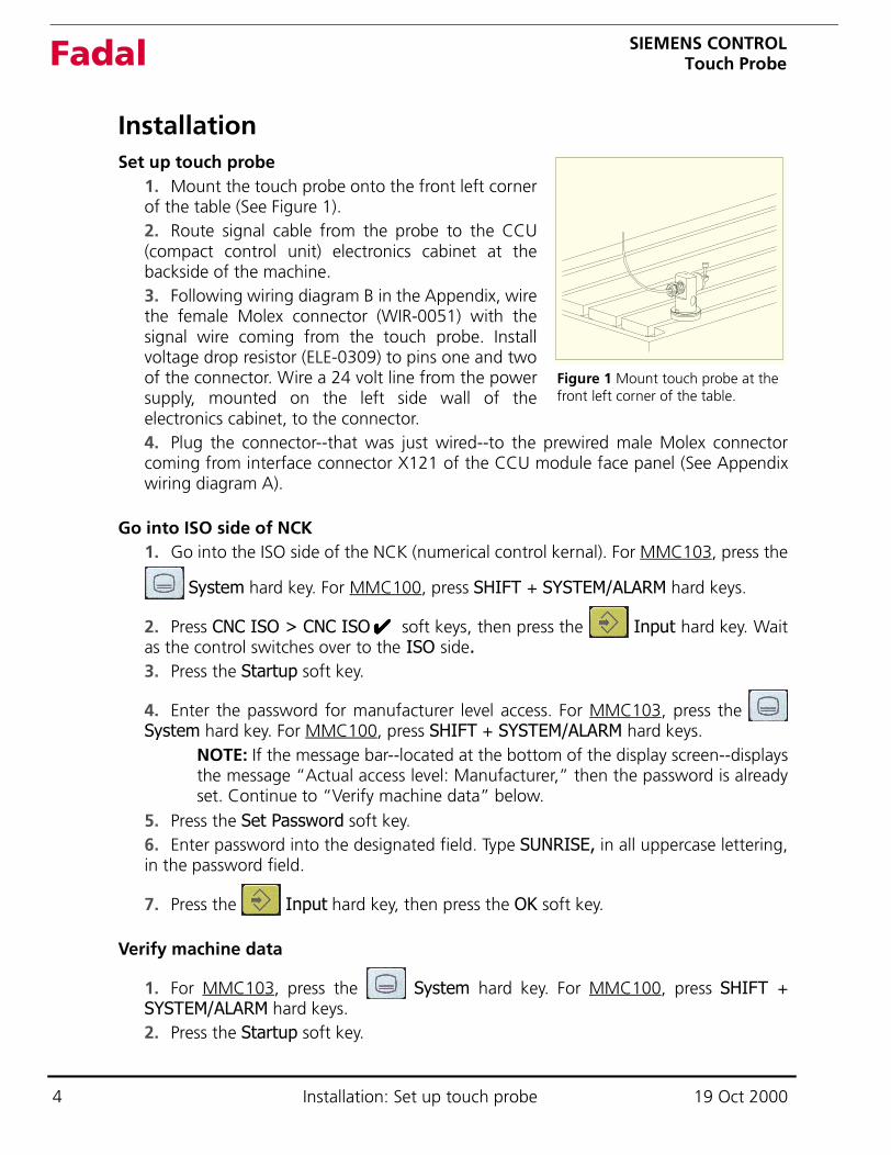
1. Mount the touch probe onto the front left cornerof the table (See Figure 1).2. Route signal cable from the probe to the CCU(compact control unit) electronics cabinet at thebackside of the machine.3. Following wiring diagram B in the Appendix, wirethe female Molex connector (WIR-0051) with thesignal wire coming from the touch probe. Installvoltage drop resistor (ELE-0309) to pins one and twoof the connector. Wire a 24 volt line from the powersupply, mounted on the left side wall of theelectronics cabinet, to the connector.4. Plug the connector--that was just wired--to the prewired male Molex connectorcoming from interface connector X121 of the CCU module face panel (See Appendixwiring diagram A).
Go into ISO side of NCK1. Go into the ISO side of the NCK (numerical control kernal). For MMC103, press the
System hard key. For MMC100, press SHIFT + SYSTEM/ALARM hard keys.
2. Press CNC ISO > CNC ISO soft keys, then press the Input hard key. Waitas the control switches over to the ISO side.3. Press the Startup soft key.
4. Enter the password for manufacturer level access. For MMC103, press the System hard key. For MMC100, press SHIFT + SYSTEM/ALARM hard keys.
NOTE: If the message bar--located at the bottom of the display screen--displaysthe message “Actual access level: Manufacturer,” then the password is alreadyset. Continue to “Verify machine data” below.
5. Press the Set Password soft key.6. Enter password into the designated field. Type SUNRISE, in all uppercase lettering,in the password field.
7. Press the Input hard key, then press the OK soft key.
Verify machine data
1. For MMC103, press the System hard key. For MMC100, press SHIFT +SYSTEM/ALARM hard keys.2. Press the Startup soft key.
Figure 1 Mount touch probe at the front left corner of the table.
✔✔✔✔
4 Installation: Set up touch probe 19 Oct 2000
SIEMENS CONTROLTouch ProbeFadal
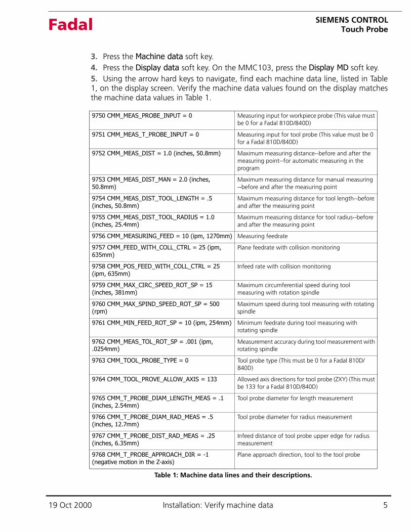
3. Press the Machine data soft key.4. Press the Display data soft key. On the MMC103, press the Display MD soft key.5. Using the arrow hard keys to navigate, find each machine data line, listed in Table1, on the display screen. Verify the machine data values found on the display matchesthe machine data values in Table 1.
9750 CMM_MEAS_PROBE_INPUT = 0 Measuring input for workpiece probe (This value must be 0 for a Fadal 810D/840D)
9751 CMM_MEAS_T_PROBE_INPUT = 0 Measuring input for tool probe (This value must be 0 for a Fadal 810D/840D)
9752 CMM_MEAS_DIST = 1.0 (inches, 50.8mm) Maximum measuring distance--before and after the measuring point--for automatic measuring in the program
9753 CMM_MEAS_DIST_MAN = 2.0 (inches, 50.8mm)
Maximum measuring distance for manual measuring --before and after the measuring point
9754 CMM_MEAS_DIST_TOOL_LENGTH = .5 (inches, 50.8mm)
Maximum measuring distance for tool length--before and after the measuring point
9755 CMM_MEAS_DIST_TOOL_RADIUS = 1.0 (inches, 25.4mm)
Maximum measuring distance for tool radius--before and after the measuring point
9756 CMM_MEASURING_FEED = 10 (ipm, 1270mm) Measuring feedrate
9757 CMM_FEED_WITH_COLL_CTRL = 25 (ipm, 635mm)
Plane feedrate with collision monitoring
9758 CMM_POS_FEED_WITH_COLL_CTRL = 25 (ipm, 635mm)
Infeed rate with collision monitoring
9759 CMM_MAX_CIRC_SPEED_ROT_SP = 15 (inches, 381mm)
Maximum circumferential speed during tool measuring with rotation spindle
9760 CMM_MAX_SPIND_SPEED_ROT_SP = 500 (rpm)
Maximum speed during tool measuring with rotating spindle
9761 CMM_MIN_FEED_ROT_SP = 10 (ipm, 254mm) Minimum feedrate during tool measuring with rotating spindle
9762 CMM_MEAS_TOL_ROT_SP = .001 (ipm, .0254mm)
Measurement accuracy during tool measurement with rotating spindle
9763 CMM_TOOL_PROBE_TYPE = 0 Tool probe type (This must be 0 for a Fadal 810D/840D)
9764 CMM_TOOL_PROVE_ALLOW_AXIS = 133 Allowed axis directions for tool probe (ZXY) (This must be 133 for a Fadal 810D/840D)
9765 CMM_T_PROBE_DIAM_LENGTH_MEAS = .1 (inches, 2.54mm)
Tool probe diameter for length measurement
9766 CMM_T_PROBE_DIAM_RAD_MEAS = .5 (inches, 12.7mm)
Tool probe diameter for radius measurement
9767 CMM_T_PROBE_DIST_RAD_MEAS = .25 (inches, 6.35mm)
Infeed distance of tool probe upper edge for radius measurement
9768 CMM_T_PROBE_APPROACH_DIR = -1 (negative motion in the Z-axis)
Plane approach direction, tool to the tool probe
Table 1: Machine data lines and their descriptions.
19 Oct 2000 Installation: Verify machine data 5
SIEMENS CONTROLTouch ProbeFadal
Verify channel data1. Press the Channel data soft key. On the MMC103, press the Channel MD soft key.2. Using the arrow keys to navigate, locate the following channel machine data lines:
• 28000 MM_REORG_LOG_FILE_MEM = 20• 28010 MM_NUM_REORG_LUD_MODULES = 8
Reset the NCK
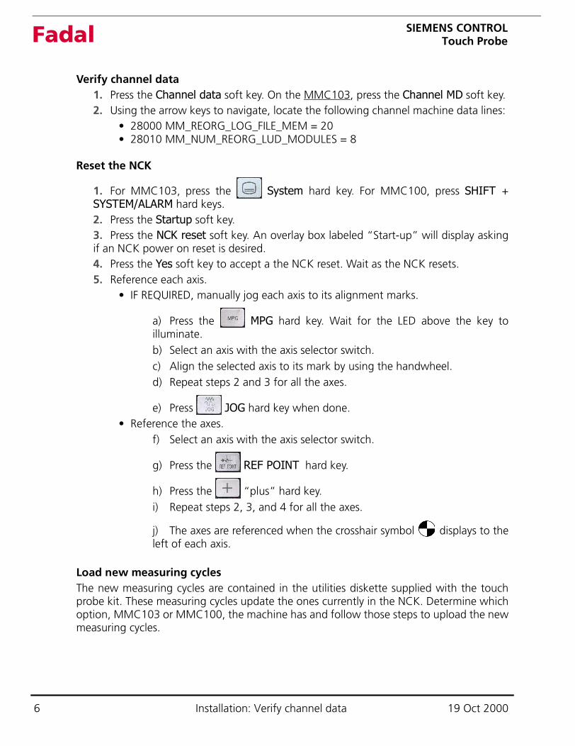
1. For MMC103, press the System hard key. For MMC100, press SHIFT +SYSTEM/ALARM hard keys.2. Press the Startup soft key.3. Press the NCK reset soft key. An overlay box labeled “Start-up” will display askingif an NCK power on reset is desired.4. Press the Yes soft key to accept a the NCK reset. Wait as the NCK resets.5. Reference each axis.
• IF REQUIRED, manually jog each axis to its alignment marks.
a) Press the MPG hard key. Wait for the LED above the key toilluminate.b) Select an axis with the axis selector switch.c) Align the selected axis to its mark by using the handwheel.d) Repeat steps 2 and 3 for all the axes.
e) Press JOG hard key when done.• Reference the axes.
f) Select an axis with the axis selector switch.
g) Press the REF POINT hard key.
h) Press the “plus” hard key.i) Repeat steps 2, 3, and 4 for all the axes.
j) The axes are referenced when the crosshair symbol displays to theleft of each axis.
Load new measuring cyclesThe new measuring cycles are contained in the utilities diskette supplied with the touchprobe kit. These measuring cycles update the ones currently in the NCK. Determine whichoption, MMC103 or MMC100, the machine has and follow those steps to upload the newmeasuring cycles.
6 Installation: Verify channel data 19 Oct 2000
SIEMENS CONTROLTouch ProbeFadal
MMC103
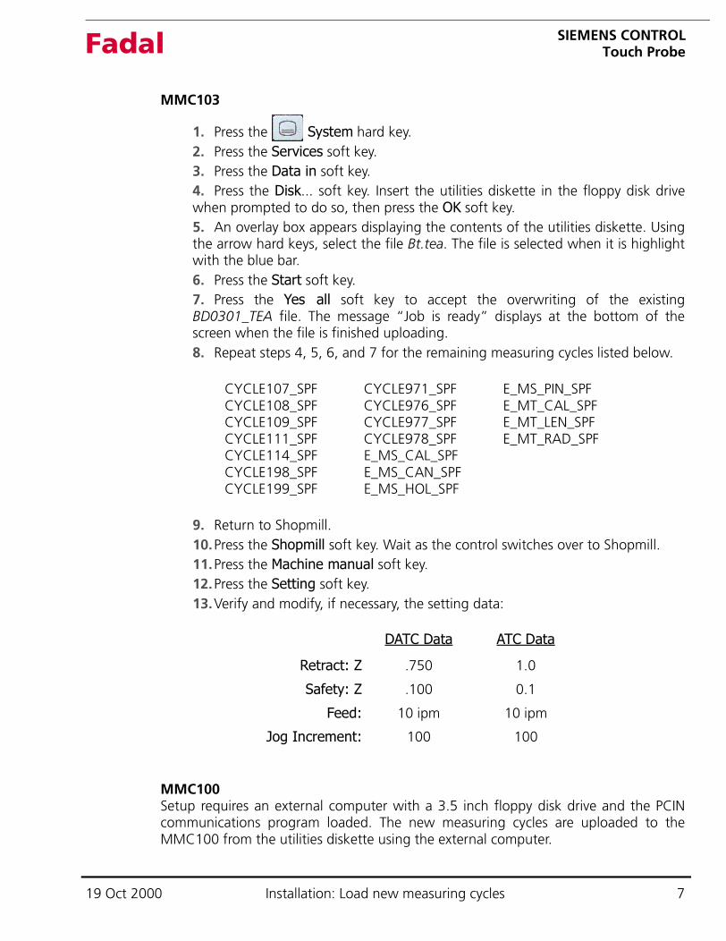
1. Press the System hard key. 2. Press the Services soft key.3. Press the Data in soft key.4. Press the Disk... soft key. Insert the utilities diskette in the floppy disk drivewhen prompted to do so, then press the OK soft key.5. An overlay box appears displaying the contents of the utilities diskette. Usingthe arrow hard keys, select the file Bt.tea. The file is selected when it is highlightwith the blue bar.6. Press the Start soft key.7. Press the Yes all soft key to accept the overwriting of the existingBD0301_TEA file. The message “Job is ready” displays at the bottom of thescreen when the file is finished uploading.8. Repeat steps 4, 5, 6, and 7 for the remaining measuring cycles listed below.
CYCLE107_SPF CYCLE971_SPF E_MS_PIN_SPFCYCLE108_SPF CYCLE976_SPF E_MT_CAL_SPFCYCLE109_SPF CYCLE977_SPF E_MT_LEN_SPFCYCLE111_SPF CYCLE978_SPF E_MT_RAD_SPFCYCLE114_SPF E_MS_CAL_SPFCYCLE198_SPF E_MS_CAN_SPFCYCLE199_SPF E_MS_HOL_SPF
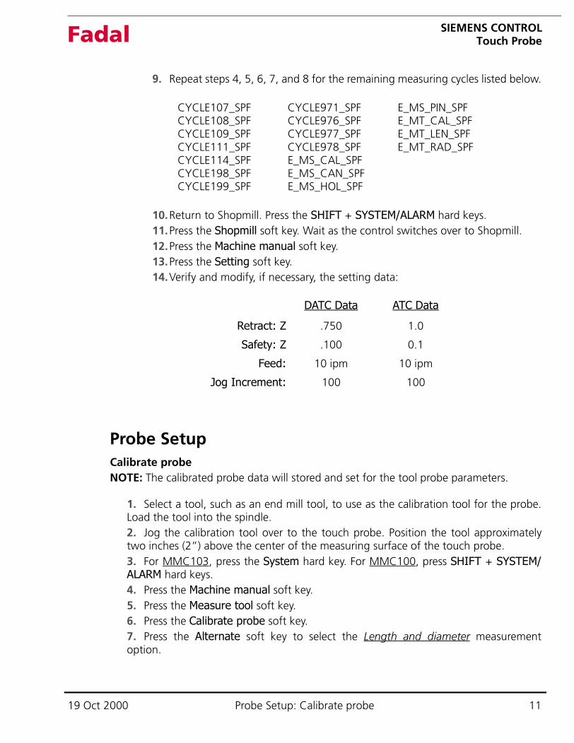
9. Return to Shopmill. 10.Press the Shopmill soft key. Wait as the control switches over to Shopmill.11.Press the Machine manual soft key.12.Press the Setting soft key.13.Verify and modify, if necessary, the setting data:
MMC100Setup requires an external computer with a 3.5 inch floppy disk drive and the PCINcommunications program loaded. The new measuring cycles are uploaded to theMMC100 from the utilities diskette using the external computer.
DATC Data ATC Data
Retract: Z .750 1.0
Safety: Z .100 0.1
Feed: 10 ipm 10 ipm
Jog Increment: 100 100
19 Oct 2000 Installation: Load new measuring cycles 7

SIEMENS CONTROLTouch ProbeFadal
Set up communications parameters1. Press the Shift + SYSTEM /ALARM hard keys.
2. Press the CNC ISO soft key, then the CNC ISO soft key.3. Verify the user access level:4. Press the Shift + SYSTEM/ALARM hard keys.5. Press the STARUP soft key.6. The message “Actual access level: Manufacturer” should display in themessage bar at the bottom of the screen display. If the level is not set toManufacturer or no message displays, continue at “d.” If the level is set toManufacturer, go to step 4.7. Press the Set password soft key.8. Type SUNRISE. The password is set in all uppercase letters. If necessary, pressthe Shift hard key while typing the password.9. Press the Shift + SYSTEM/ALARM hard keys.10.Press the Services soft key.11.Press the Data out soft key.12.Highlight the Start-up data line using the up and down arrows.13.Press the RS232 C User vertical soft key.14.Press the Set soft key. At this point, two options columns are displayed (SeeFigure 2). The left options column is the parameters for communications. Theright options column is the “Special Functions.”
✔✔✔✔
Figure 2 Communications parameter settings for MMC100.
8 Installation: Load new measuring cycles 19 Oct 2000
SIEMENS CONTROLTouch ProbeFadal
The parameters for communications should be as follows:
Interface: COM1Protocol: RTS/CTSBaud Rate: 2400 (see note below)Stop Bits: 1Parity: noneData bits: 8Xon: 11Xoff: 13End of Trans: 03
NOTE: On external computers loaded with either the Windows 95 or NT 4.0operation system, a baud rate of 4800bps or higher may also be used. Onexternal computers loaded with the Windows 98 operating system, setting abaud rate above 2400bps can cause a data transmission failure. In either case,if a transmission failure were to occur, use a baud rate of 2400bps.
“Binary Format (PC form)” should be selected on the second-to-last line inthe Special Functions column. Also, all the boxes to the left of each line, in theSpecial Functions column, should be clear.
15.Press the Save setting vertical soft key.
Set up external computerThe communication parameters at the external computer must correspond to thecommunication parameters at the control. If applicable, set LPT1 to bi-directional inthe BIOS of the external computer.
NOTE: The PCIN communications program is a DOS based program. Therefore, anRTS/CTS error may occur if PCIN is being run in Microsoft Windows. If an error occurs,try turning off power management in Windows, turning off the screen saver, andrestarting the computer in DOS mode. If an error still occurs, consult your ITdepartment for further assistance.
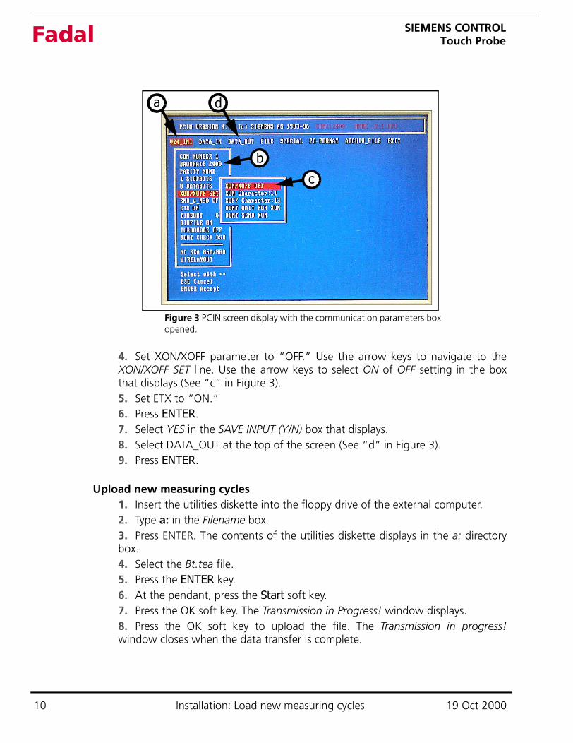
1. Start up the PCIN communications program.2. Select V24_INI at the top of the screen (See “a” in Figure 3). Press ENTER,two times if necessary, to display the communication parameters box.3. Set COM number to “1” or “2” (depending on the COM portcommunications cable connection at the external computer). Navigate to theCOM NUMBER line using the arrow keys. Use the arrow keys to select the properCOM port settings (See “b” in Figure 3).
19 Oct 2000 Installation: Load new measuring cycles 9
SIEMENS CONTROLTouch ProbeFadal
4. Set XON/XOFF parameter to “OFF.” Use the arrow keys to navigate to theXON/XOFF SET line. Use the arrow keys to select ON of OFF setting in the boxthat displays (See “c” in Figure 3).5. Set ETX to “ON.”6. Press ENTER.7. Select YES in the SAVE INPUT (Y/N) box that displays.8. Select DATA_OUT at the top of the screen (See “d” in Figure 3).9. Press ENTER.
Upload new measuring cycles1. Insert the utilities diskette into the floppy drive of the external computer.2. Type a: in the Filename box.3. Press ENTER. The contents of the utilities diskette displays in the a: directorybox.4. Select the Bt.tea file.5. Press the ENTER key.6. At the pendant, press the Start soft key.7. Press the OK soft key. The Transmission in Progress! window displays.8. Press the OK soft key to upload the file. The Transmission in progress!window closes when the data transfer is complete.
a
b
Figure 3 PCIN screen display with the communication parameters box opened.
c
d
10 Installation: Load new measuring cycles 19 Oct 2000
SIEMENS CONTROLTouch ProbeFadal
9. Repeat steps 4, 5, 6, 7, and 8 for the remaining measuring cycles listed below.
CYCLE107_SPF CYCLE971_SPF E_MS_PIN_SPFCYCLE108_SPF CYCLE976_SPF E_MT_CAL_SPFCYCLE109_SPF CYCLE977_SPF E_MT_LEN_SPFCYCLE111_SPF CYCLE978_SPF E_MT_RAD_SPFCYCLE114_SPF E_MS_CAL_SPFCYCLE198_SPF E_MS_CAN_SPFCYCLE199_SPF E_MS_HOL_SPF
10.Return to Shopmill. Press the SHIFT + SYSTEM/ALARM hard keys.11.Press the Shopmill soft key. Wait as the control switches over to Shopmill.12.Press the Machine manual soft key.13.Press the Setting soft key.14.Verify and modify, if necessary, the setting data:
Probe SetupCalibrate probeNOTE: The calibrated probe data will stored and set for the tool probe parameters.
1. Select a tool, such as an end mill tool, to use as the calibration tool for the probe.Load the tool into the spindle.2. Jog the calibration tool over to the touch probe. Position the tool approximatelytwo inches (2”) above the center of the measuring surface of the touch probe.3. For MMC103, press the System hard key. For MMC100, press SHIFT + SYSTEM/ALARM hard keys.4. Press the Machine manual soft key.5. Press the Measure tool soft key.6. Press the Calibrate probe soft key.7. Press the Alternate soft key to select the Length and diameter measurementoption.
DATC Data ATC Data
Retract: Z .750 1.0
Safety: Z .100 0.1
Feed: 10 ipm 10 ipm
Jog Increment: 100 100
19 Oct 2000 Probe Setup: Calibrate probe 11
SIEMENS CONTROLTouch ProbeFadal
8. Press the CYCLE START (green) hard key. Calibration is executedautomatically at the measuring feedrate. The current distance measurements betweenthe machine zero and touch probe are calculated and stored in an internal data area.
Setup tools in Tool List1. For MMC103, press the System hard key. For MMC100, press SHIFT + SYSTEM/ALARM hard keys.2. Press the Tool zero offset soft key.3. Modify the tools in the tool list so they correspond to the tools in the turret.NOTE: Endmills require a diameter and “endmill” selected as the description. Drillsrequire an angle and “drill” selected as the description.
Measure tool1. For MMC103, press the System hard key. For MMC100, press SHIFT + SYSTEM/ALARM hard keys.2. Press the Machine Manual soft key.3. Press the Measure tool soft key.4. Position the tool close to the measuring surface of the touch probe.5. Press the Length auto soft key.
6. Press the CYCLE START hard key. The measurement is taken automatically atthe measuring feedrate. The tool dimension data is calculated and stored in the toollist.7. Load the next tool from the turret.8. Repeat this step for all the tools being measured.
12 Probe Setup: Setup tools in Tool List 19 Oct 2000
SIEMENS CONTROLTouch ProbeFadal
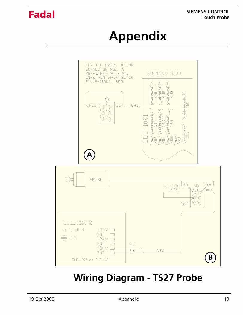
Appendix
Wiring Diagram - TS27 Probe
A
B
19 Oct 2000 Appendix: 13

SIEMENS CONTROLTouch ProbeFadal
This page intentionally left blank.
14 : 19 Oct 2000