toward controllable growth of carbon...
TRANSCRIPT
Toward Controllable Growth of Carbon Nanotubes
Avetik R. Harutyunyan
Materials Science Division, Columbus Ohio, USA
(April 10, 2011)
Honda Research Institute USA Inc.
The 5th Rice University/Air Force Research Laboratory/NASAWorkshop on Nucleation and Growth Mechanisms of SWCNTs April 8-12, 2011, Guadalupe, Texas

© 2009 Honda Research Institute USA, Inc.Confidential 2
Coauthors and collaborators
Dr. Gugang Chen Honda Research Institute USA Inc.Dr. Elena PigosDr. Tereza Paronyan
Prof. Eric A. Stach Brookhaven National LaboratoryDr. Dmitri Zakharov Brookhaven National Laboratory
Dr. Seung Min Kim Purdue University
Prof. Boris Yakobson Rice University
Prof. Bruce Weisman Rice UniversityDr. Anton Naumov
Prof. Millie Dresselhaus MITProf. Jing Kong
Outline of the talk
1. Introduction: Highlighted "Key Questions" from previous Workshop
2. Thermodynamic aspects of carbon nanotube growth
3. Summary: Hints for selective growth
4. Preferential growth of metallic tubes: The origin of selectivity
5. Conclusion: control parameters3
© 2009 Honda Research Institute USA, Inc.Confidential 4
Ubiquitous applications of SWCNTs demand
reasonably homogeneous material
Introduction
Controllable growth
Growth mechanism
© 2009 Honda Research Institute USA, Inc.Confidential 5
State of catalyst - solid (crystal/disorder) vs liquid
Diffusion path - surface vs bulk, sublayer diffusion
Role of carbides - promote vs terminate the growth
"Key Questions" from previous Workshop
© 2009 Honda Research Institute USA, Inc.Confidential 6
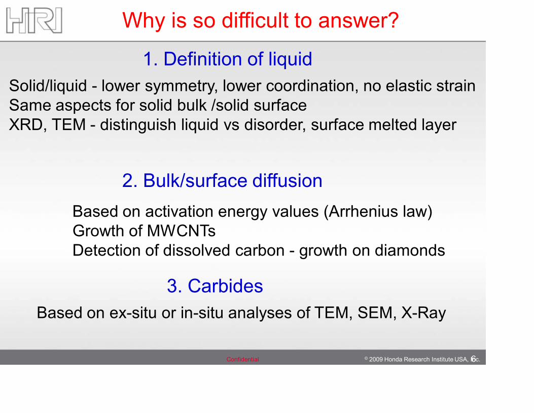
Why is so difficult to answer?
1. Definition of liquid Solid/liquid - lower symmetry, lower coordination, no elastic strainSame aspects for solid bulk /solid surface XRD, TEM - distinguish liquid vs disorder, surface melted layer
2. Bulk/surface diffusionBased on activation energy values (Arrhenius law)Growth of MWCNTs Detection of dissolved carbon - growth on diamonds
3. CarbidesBased on ex-situ or in-situ analyses of TEM, SEM, X-Ray
© 2009 Honda Research Institute USA, Inc.Confidential 7
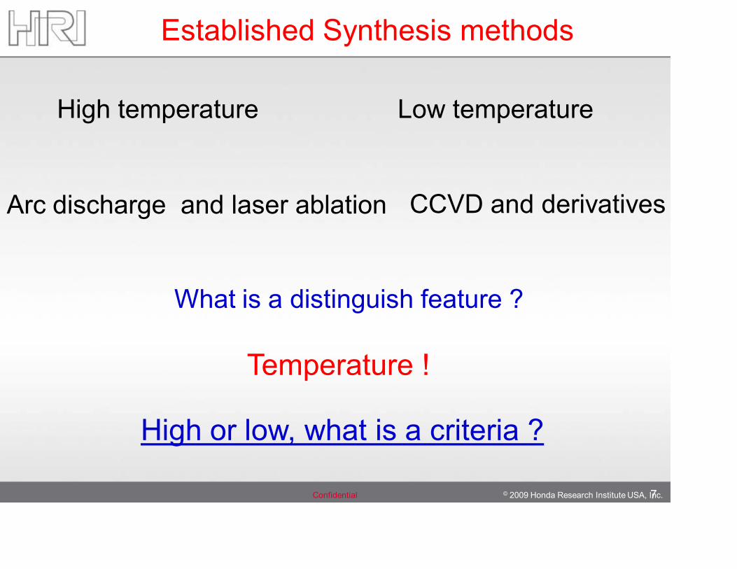
High temperature
Arc discharge and laser ablation
Low temperature
CCVD and derivatives
What is a distinguish feature ?
Temperature !
High or low, what is a criteria ?
Established Synthesis methods
© 2009 Honda Research Institute USA, Inc.Confidential 8
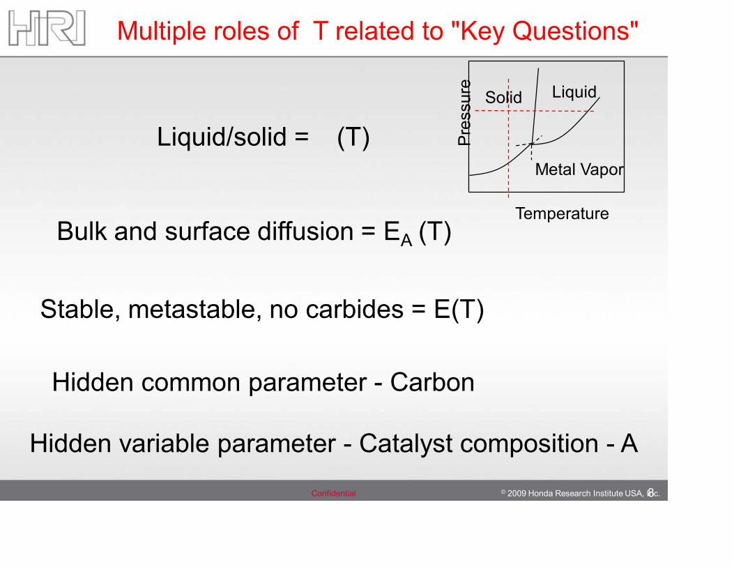
Liquid/solid = (T)
Multiple roles of T related to "Key Questions"
Bulk and surface diffusion = EA (T)
Stable, metastable, no carbides = E(T)
Hidden common parameter - Carbon
Hidden variable parameter - Catalyst composition - AP
ress
ure
Temperature
Solid Liquid
Metal Vapor
© 2009 Honda Research Institute USA, Inc.Confidential 9
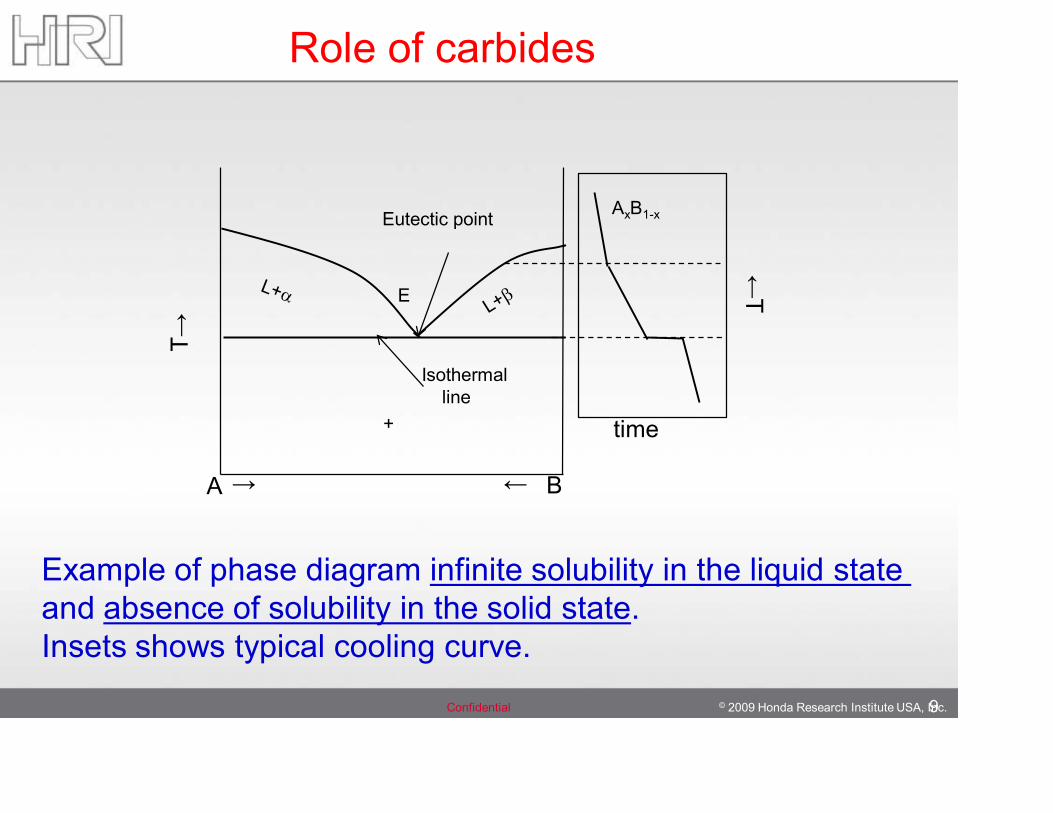
A B→ ←
Eutectic point
Isothermalline
+
T→
←T
time
AxB1-x
E
Example of phase diagram infinite solubility in the liquid state and absence of solubility in the solid state.Insets shows typical cooling curve.
Role of carbides
© 2009 Honda Research Institute USA, Inc.Confidential 10
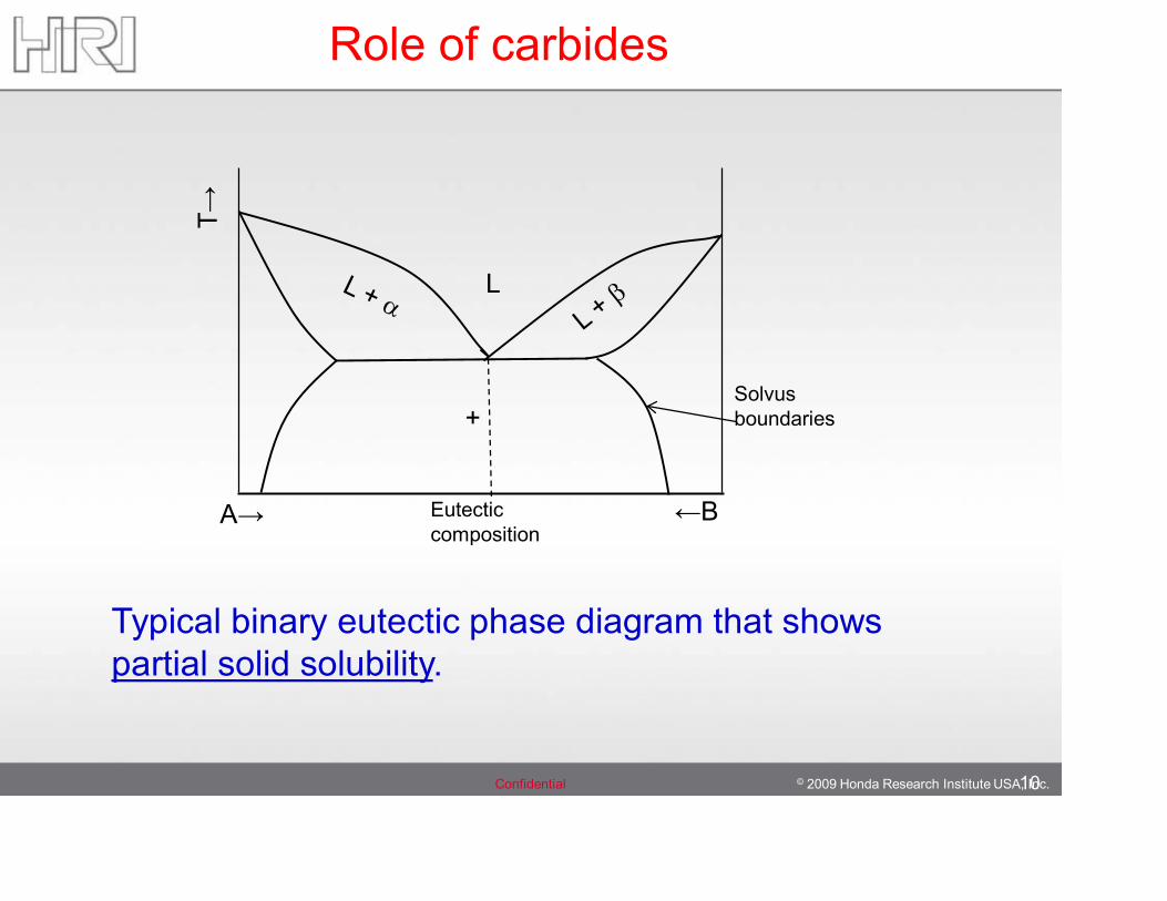
A→ ←B
+
L
T→
Solvus boundaries
Eutectic composition
Typical binary eutectic phase diagram that shows partial solid solubility.
Role of carbides
© 2009 Honda Research Institute USA, Inc.Confidential
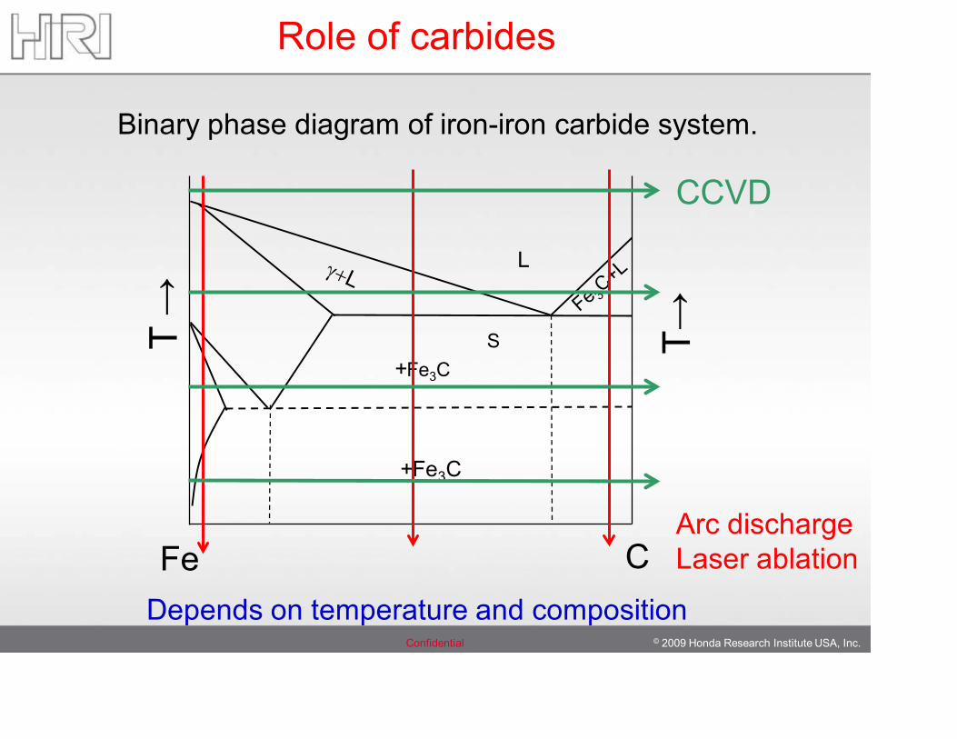
Role of carbides
Binary phase diagram of iron-iron carbide system.
Depends on temperature and composition
L
+Fe3CS
Fe C
T →
T→
+Fe3C
CCVD
Arc dischargeLaser ablation
© 2009 Honda Research Institute USA, Inc.Confidential 12
Key Questions
(T,C)AFA =
© 2009 Honda Research Institute USA, Inc.Confidential 13
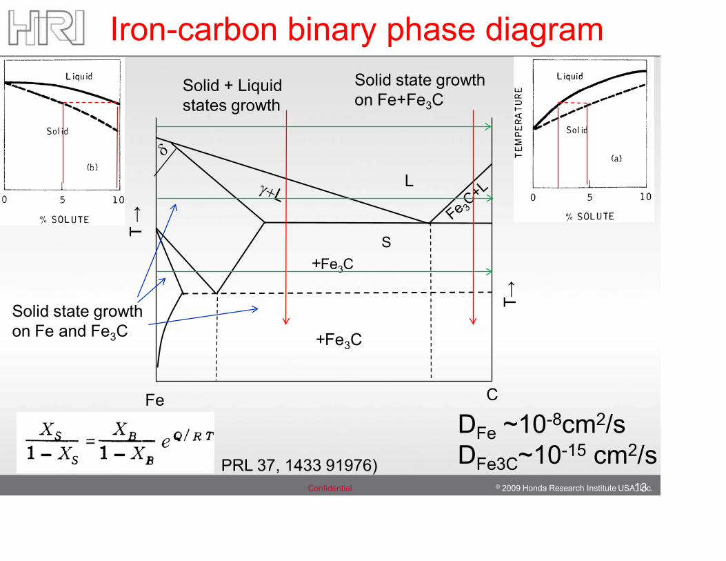
Iron-carbon binary phase diagram
L
+Fe3CS
Fe C
T →
T→
+Fe3C
Solid state growthon Fe and Fe3C
Solid + Liquid states growth
Solid state growthon Fe+Fe3C
DFe ~10-8cm2/sDFe3C~10-15 cm2/sPRL 37, 1433 91976)
© 2009 Honda Research Institute USA, Inc.Confidential 14
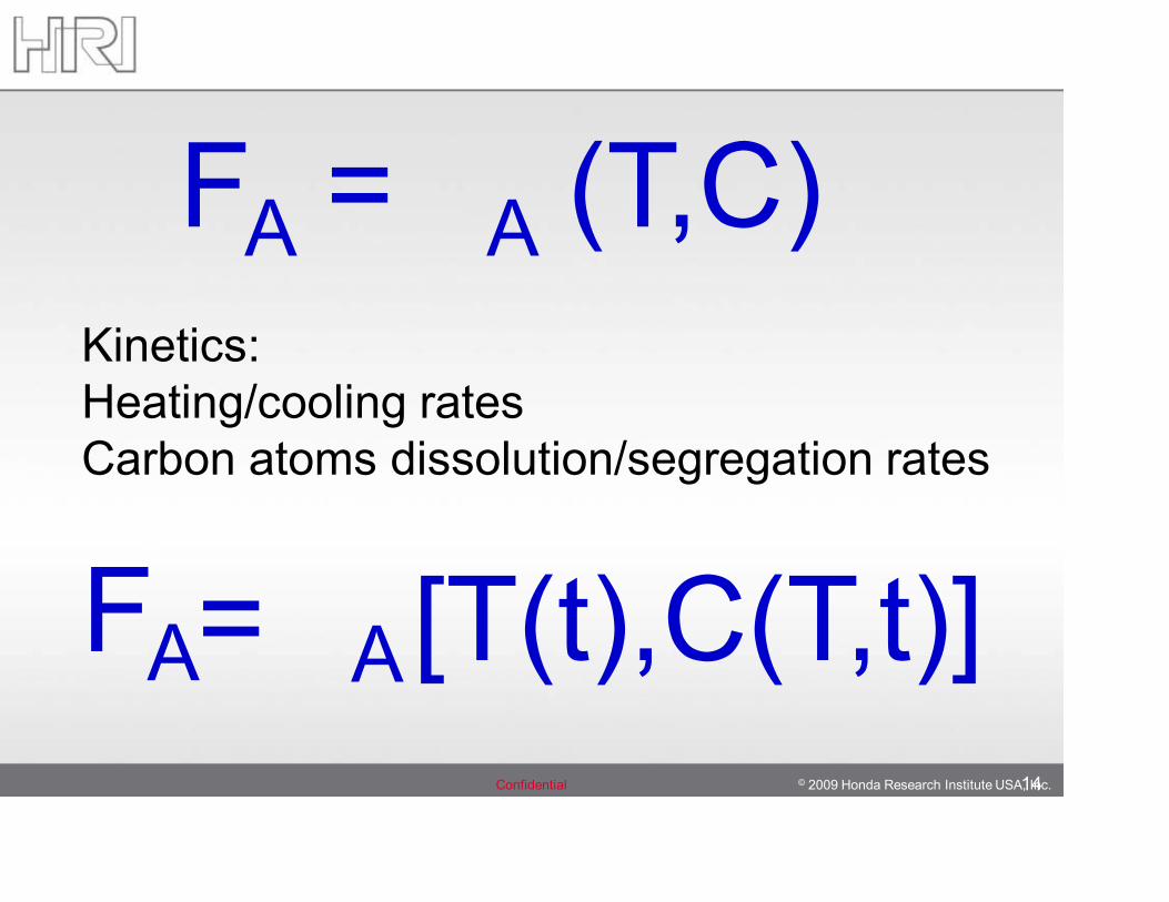
[T(t),C(T,t)]AFA=
Kinetics:Heating/cooling ratesCarbon atoms dissolution/segregation rates
FA = A (T,C)
© 2009 Honda Research Institute USA, Inc.Confidential 15
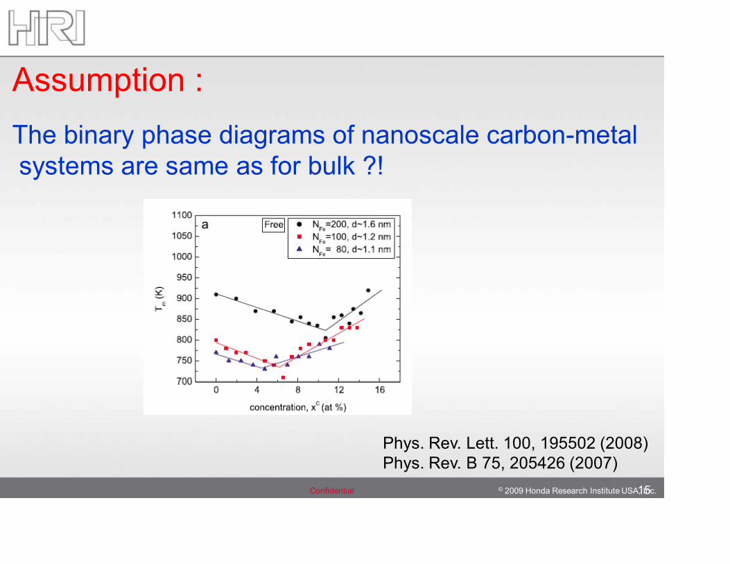
Assumption :The binary phase diagrams of nanoscale carbon-metalsystems are same as for bulk ?!
Phys. Rev. Lett. 100, 195502 (2008)Phys. Rev. B 75, 205426 (2007)
© 2009 Honda Research Institute USA, Inc.Confidential 16
Towards chiral-selective synthesis
What potential control parameters do we have currently ?
1.Catalyst diameter-on some level controls the diameter of tubes
2.Catalyst structure - may correlate with the tube structure
How to exploit these features of catalyst ?
Ensure that catalyst is in solid state
© 2009 Honda Research Institute USA, Inc.Confidential 17
S. M. Bachilo,…, D. Resasco JACS 125 (2003)CVD Growth of SWCNTs with narrow chirality distribution
Li et al., Nano Lett. 4, 317 (2004)Preferential growth by a plasma enhanced CVD method~90 % semiconducting tubes
Qu, et al., Nano Lett. 8, 2682 (2008)Fast heating combined with plasma enhanced CVD~ 96% semiconducting tubes
Origin of selectivity is not known
W. H. Chiang, R. M. Sankaran Nature Mat., 8, 882, 2009Exploiting atmospheric-pressure microplasma techniqueConclusion:Epitaxial relationship between SWCNTs chirality and the catalyst structure
Selective synthesis
18
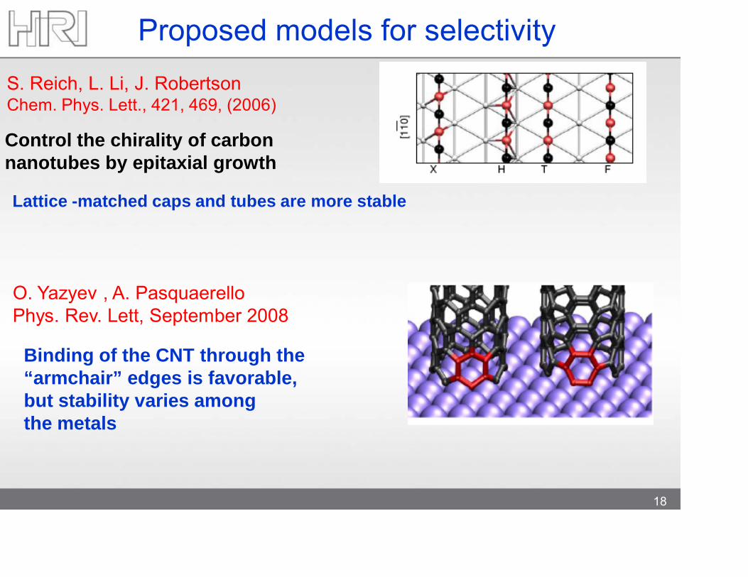
Proposed models for selectivityS. Reich, L. Li, J. RobertsonChem. Phys. Lett., 421, 469, (2006)
Lattice -matched caps and tubes are more stable
O. Yazyev , A. PasquaerelloPhys. Rev. Lett, September 2008
Binding of the CNT through the “armchair” edges is favorable, but stability varies among the metals
Control the chirality of carbon nanotubes by epitaxial growth
© 2009 Honda Research Institute USA, Inc.Confidential 19
By varying the noble gas ambient He and Ar during Fe catalyst
conditioning in the presence of H2 and H2O species, we altered
fraction of tubes with metallic conductivity from 1/3 up to a max of
90%.
Our results
Science 326, 116 (2009)
20
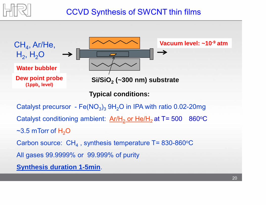
CCVD Synthesis of SWCNT thin films
Si/SiO2 (~300 nm) substrate
Typical conditions:
Catalyst precursor - Fe(NO3)3 9H2O in IPA with ratio 0.02-20mg
Catalyst conditioning ambient: Ar/H2 or He/H2 at T= 500 860oC
~3.5 mTorr of H2O
Carbon source: CH4 , synthesis temperature T= 830-860oC
All gases 99.9999% or 99.999% of purity
Synthesis duration 1-5min.
Water bubblerDew point probe
(1ppbv level)
Vacuum level: ~10-9 atmCH4, Ar/He, H2, H2O
© 2009 Honda Research Institute USA, Inc.Confidential 21
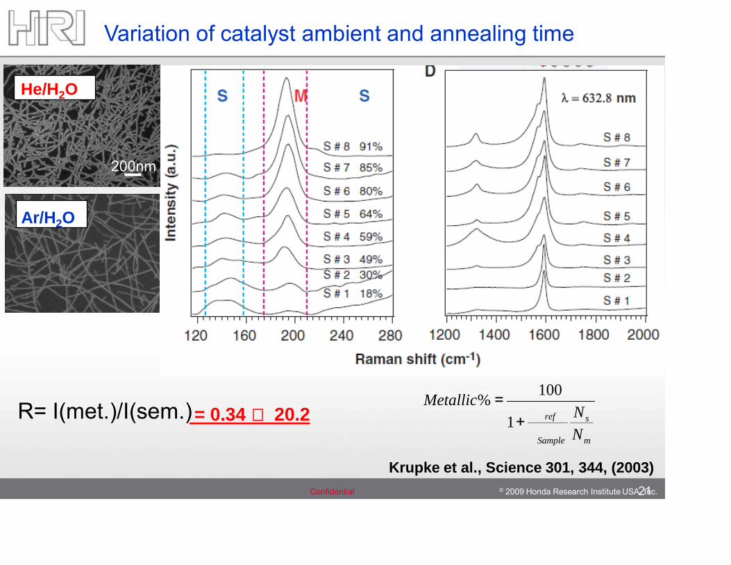
Variation of catalyst ambient and annealing time
R= I(met.)/I(sem.)= 0.34 20.2m
s
Sample
ref
NN
Metallic
+=
1
100%
Krupke et al., Science 301, 344, (2003)
200nm
200nm
He/H2O
200nm
Ar/H2O
22
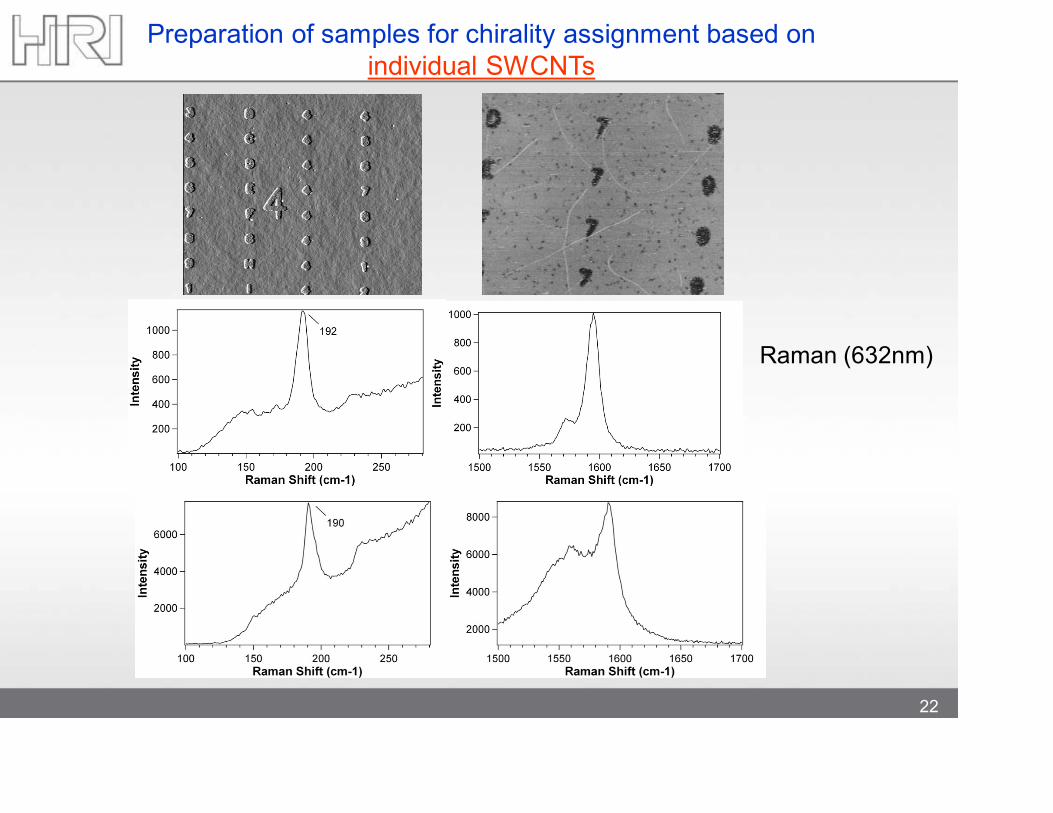
Preparation of samples for chirality assignment based on individual SWCNTs
Raman (632nm)
23
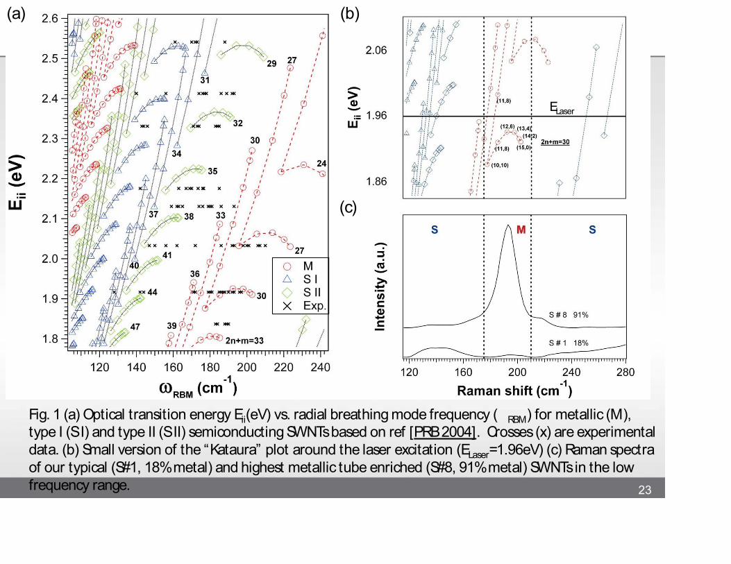
Fig. 1 (a) Optical transition energy Eii(eV) vs. radial breathing mode frequency (RBM) for metallic (M), type I (S I) and type II (S II) semiconducting SWNTs based on ref [PRB 2004]. Crosses (x) are experimental data. (b) Small version of the “Kataura” plot around the laser excitation (ELaser=1.96eV) (c) Raman spectra of our typical (S#1, 18% metal) and highest metallic tube enriched (S#8, 91% metal) SWNTs in the low frequency range.
(a) (b)
(c)
ELaser
24
1m
Ω≈ KR 47
Ω≈ KR 710
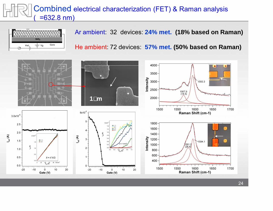
Combined electrical characterization (FET) & Raman analysis (=632.8 nm)
Ar ambient: 32 devices: 24% met. (18% based on Raman)
He ambient: 72 devices: 57% met. (50% based on Raman)
25
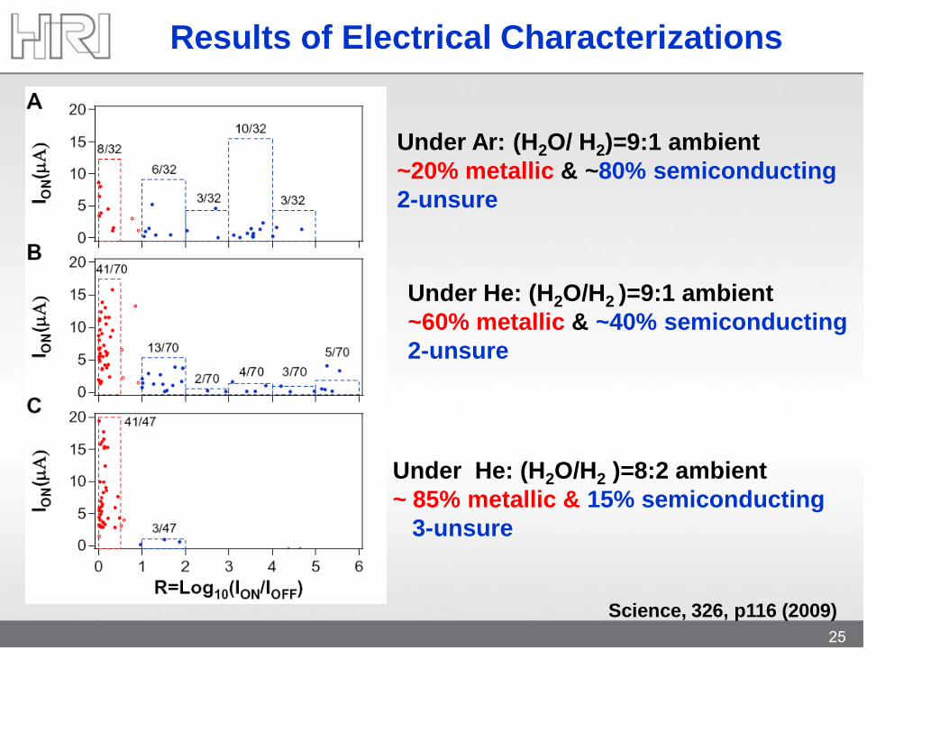
Results of Electrical Characterizations
Under Ar: (H2O/ H2)=9:1 ambient~20% metallic & ~80% semiconducting2-unsure
Under He: (H2O/H2 )=9:1 ambient~60% metallic & ~40% semiconducting2-unsure
Under He: (H2O/H2 )=8:2 ambient~ 85% metallic & 15% semiconducting
3-unsure
Science, 326, p116 (2009)
26
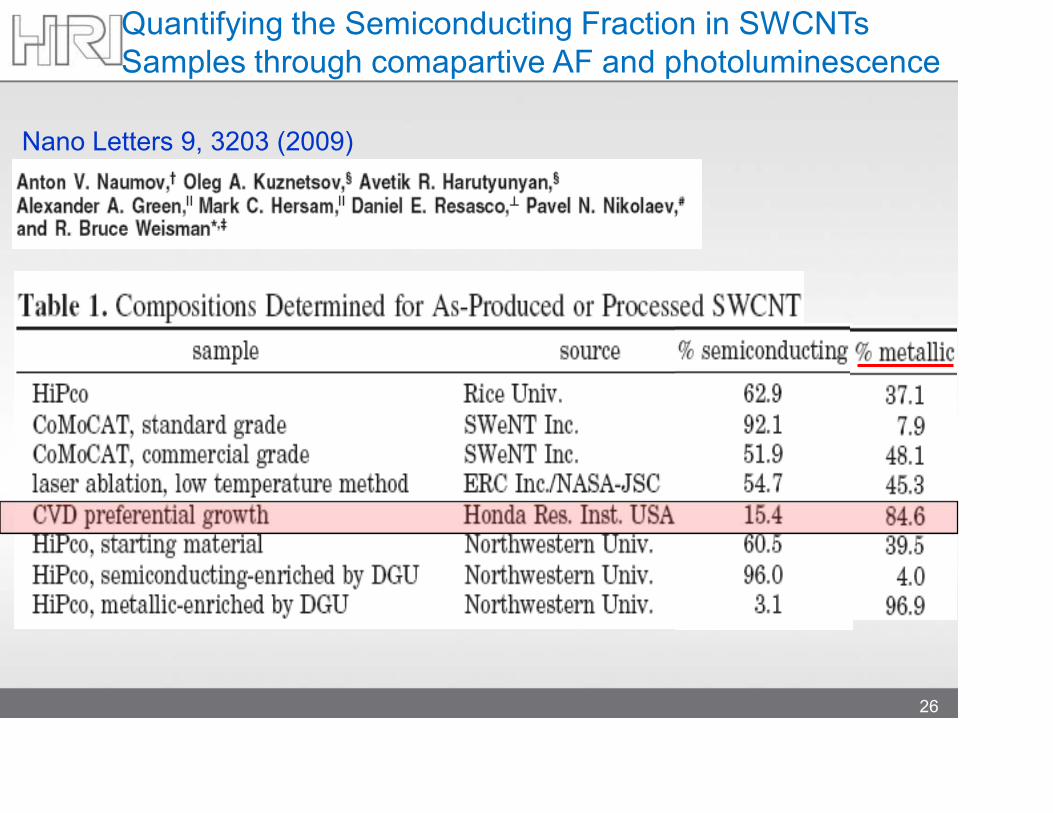
Quantifying the Semiconducting Fraction in SWCNTs Samples through comapartive AF and photoluminescence
Nano Letters 9, 3203 (2009)
27
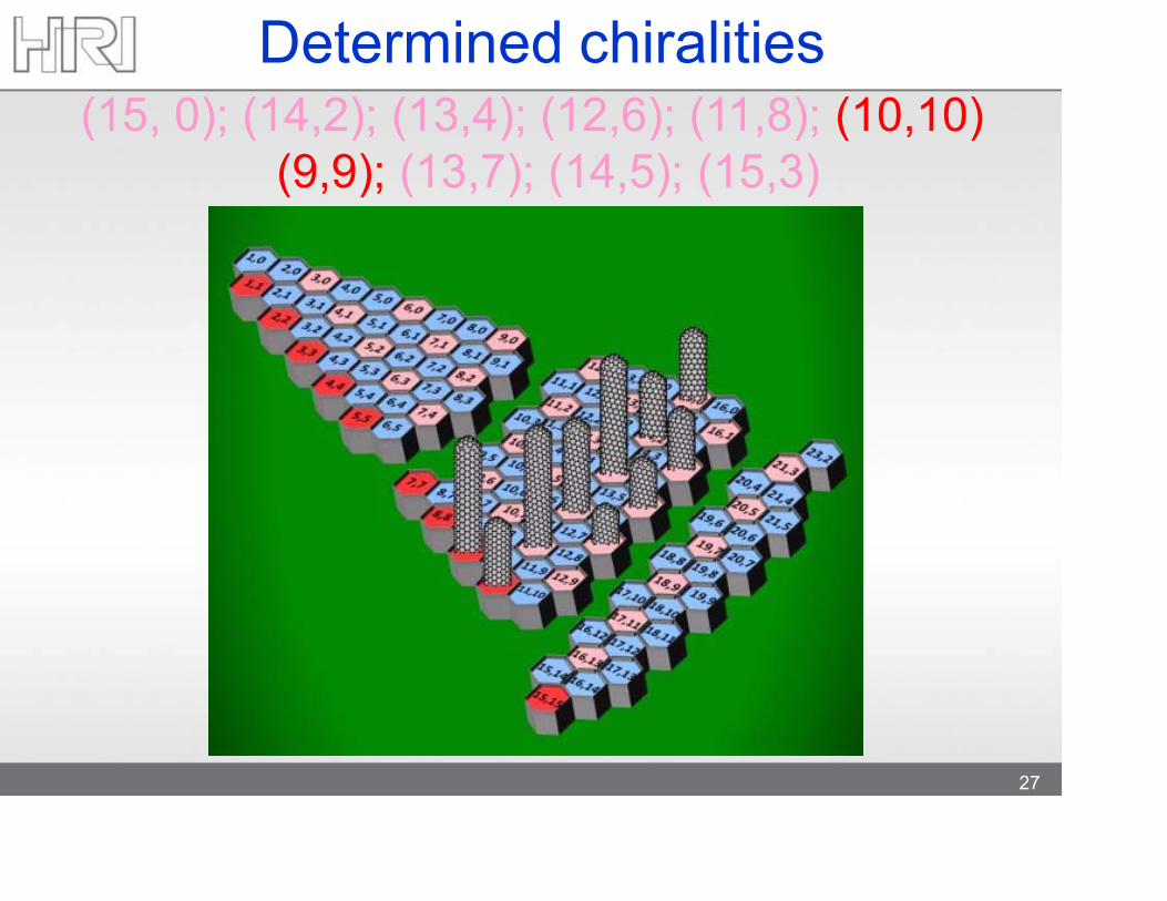
(15, 0); (14,2); (13,4); (12,6); (11,8); (10,10) (9,9); (13,7); (14,5); (15,3)
Determined chiralities
28
Origin of preferential growth ?
29
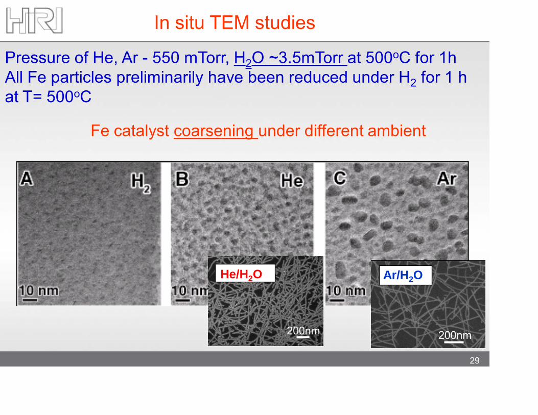
Fe catalyst coarsening under different ambient
Pressure of He, Ar - 550 mTorr, H2O ~3.5mTorr at 500oC for 1hAll Fe particles preliminarily have been reduced under H2 for 1 hat T= 500oC
In situ TEM studies
200nm
200nm
He/H2O
200nm
Ar/H2O
© 2009 Honda Research Institute USA, Inc.Confidential 30
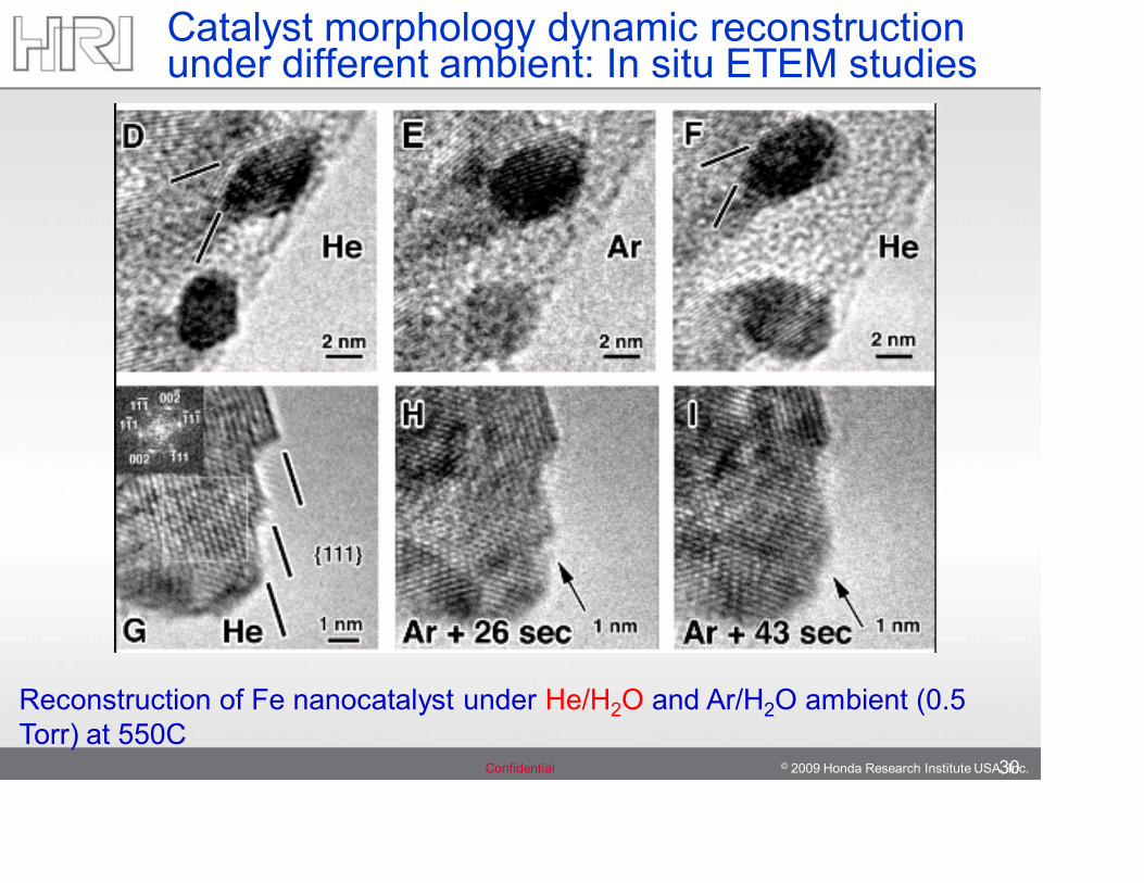
Catalyst morphology dynamic reconstruction under different ambient: In situ ETEM studies
Reconstruction of Fe nanocatalyst under He/H2O and Ar/H2O ambient (0.5 Torr) at 550C
31
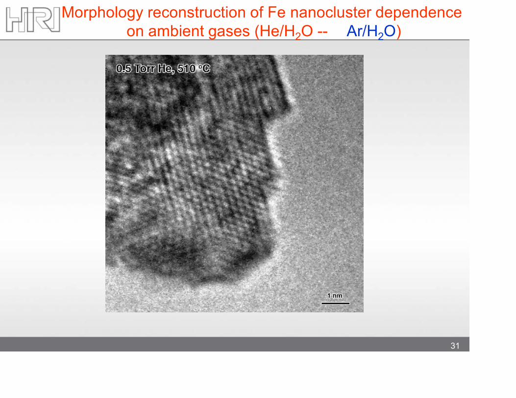
Morphology reconstruction of Fe nanocluster dependence on ambient gases (He/H2O -- Ar/H2O)
32
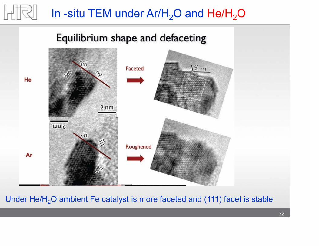
In -situ TEM under Ar/H2O and He/H2O
Under He/H2O ambient Fe catalyst is more faceted and (111) facet is stable
© 2009 Honda Research Institute USA, Inc.Confidential 33
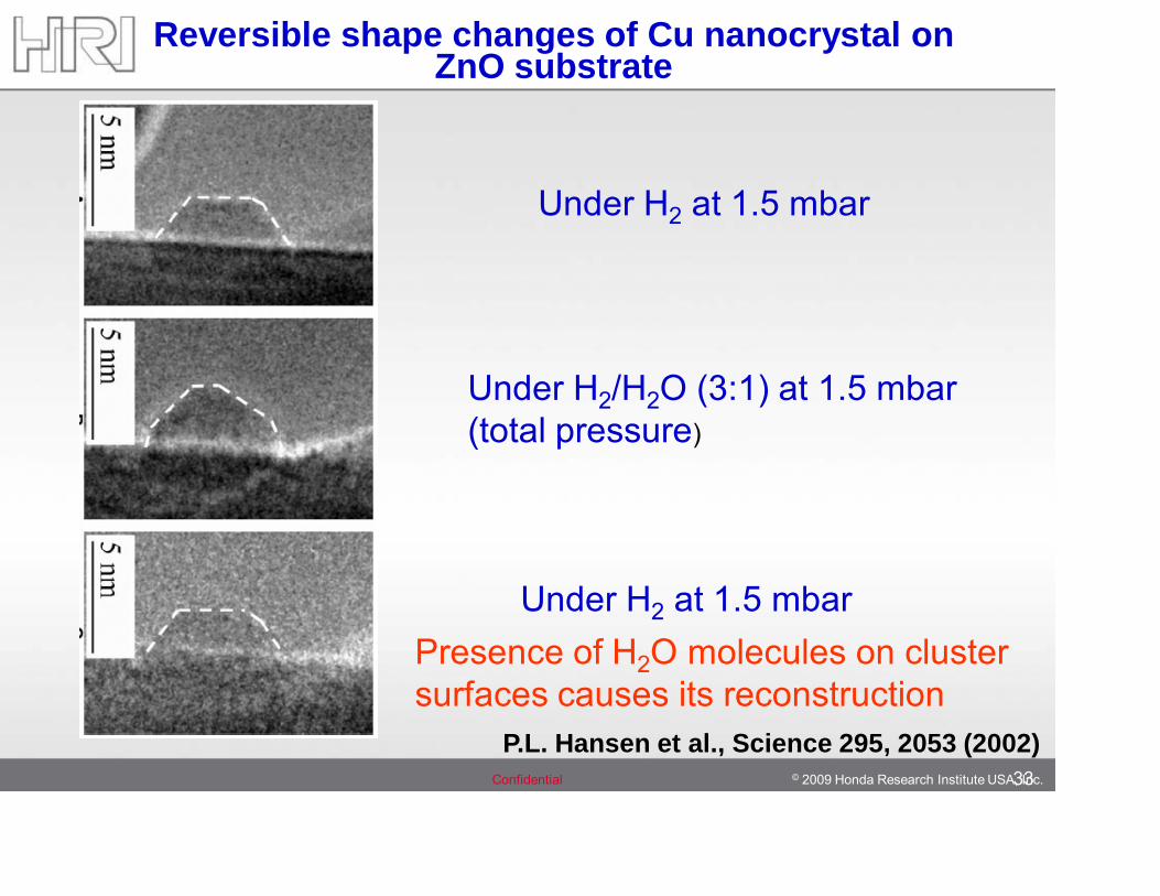
Reversible shape changes of Cu nanocrystal on ZnO substrate
Under H2 at 1.5 mbar
Under H2/H2O (3:1) at 1.5 mbar (total pressure)
Under H2 at 1.5 mbar
P.L. Hansen et al., Science 295, 2053 (2002)
Presence of H2O molecules on cluster surfaces causes its reconstruction
34
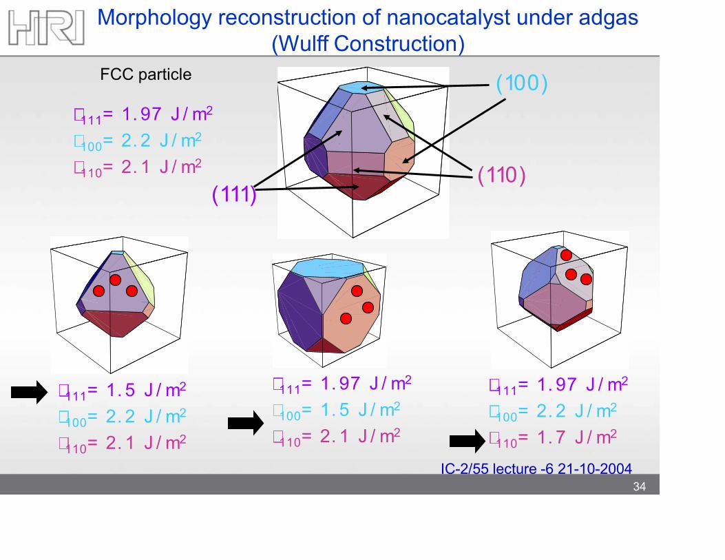
111= 1. 97 J / m2
100= 2. 2 J / m2
110= 2. 1 J / m2
(100)
(110)(111)
111= 1. 5 J / m2
100= 2. 2 J / m2
110= 2. 1 J / m2
111= 1. 97 J / m2
100= 1. 5 J / m2
110= 2. 1 J / m2
111= 1. 97 J / m2
100= 2. 2 J / m2
110= 1. 7 J / m2
Morphology reconstruction of nanocatalyst under adgas(Wulff Construction)
34IC-2/55 lecture -6 21-10-2004
FCC particle
What is a mechanism of selectivity ?
Is there epitaxial relationship between metal catalyst structure and grown nanotube chirality?
35
36
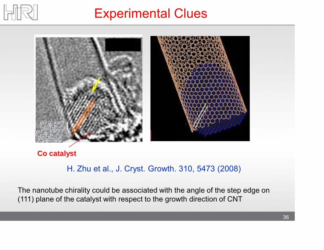
H. Zhu et al., J. Cryst. Growth. 310, 5473 (2008)
Experimental Clues
Co catalyst
The nanotube chirality could be associated with the angle of the step edge on (111) plane of the catalyst with respect to the growth direction of CNT
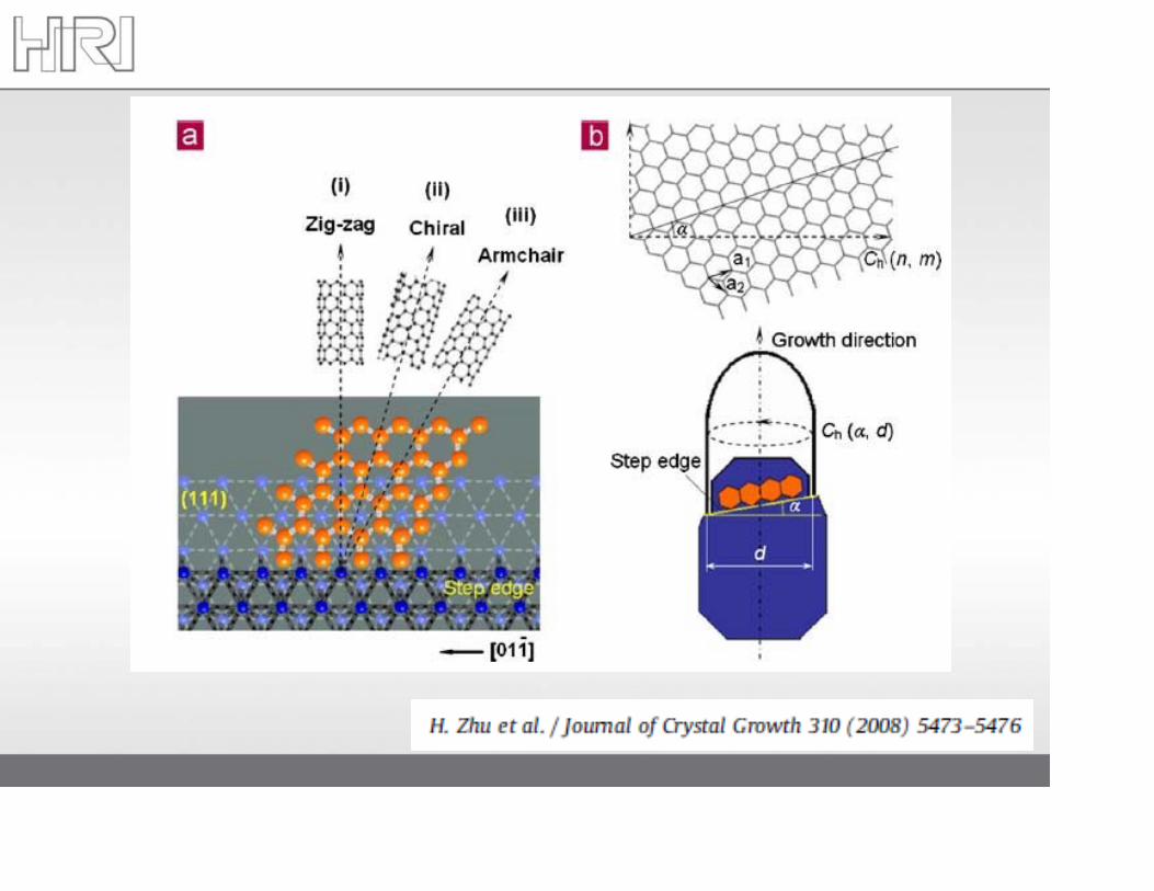
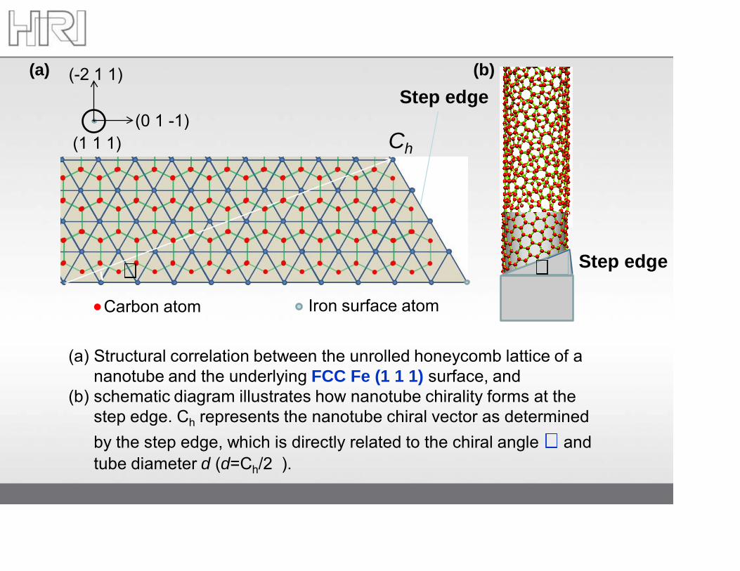
(a) Structural correlation between the unrolled honeycomb lattice of a nanotube and the underlying FCC Fe (1 1 1) surface, and
(b) schematic diagram illustrates how nanotube chirality forms at the step edge. Ch represents the nanotube chiral vector as determined by the step edge, which is directly related to the chiral angle and tube diameter d (d=Ch/2).
Carbon atom Iron surface atom
(0 1 -1)
(-2 1 1)
(1 1 1) Ch
Step edge(a) (b)
Step edge
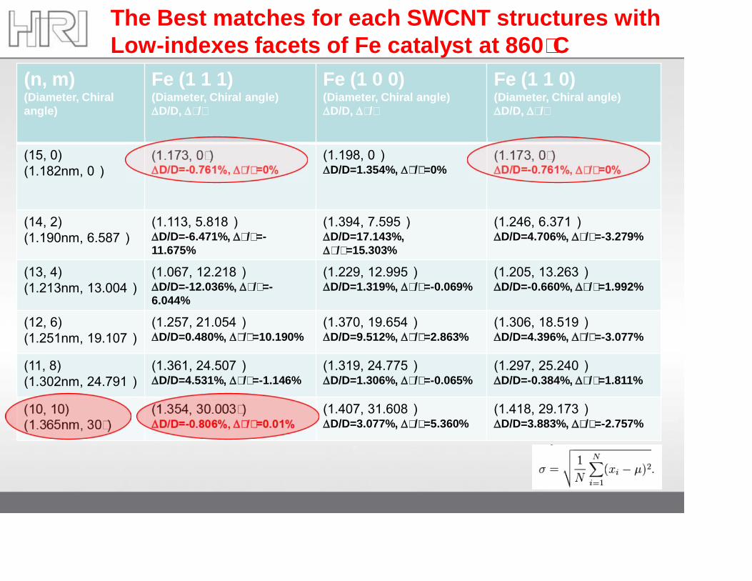
(n, m)(Diameter, Chiral angle)
Fe (1 1 1)(Diameter, Chiral angle)∆D/D, ∆/
Fe (1 0 0)(Diameter, Chiral angle)∆D/D, ∆/
Fe (1 1 0)(Diameter, Chiral angle)∆D/D, ∆/
(15, 0) (1.182nm, 0)
(1.173, 0)∆D/D=-0.761%, ∆/=0%
(1.198, 0)∆D/D=1.354%, ∆/=0%
(1.173, 0)∆D/D=-0.761%, ∆/=0%
(14, 2) (1.190nm, 6.587)
(1.113, 5.818)∆D/D=-6.471%, ∆/=-11.675%
(1.394, 7.595)∆D/D=17.143%, ∆/=15.303%
(1.246, 6.371)∆D/D=4.706%, ∆/=-3.279%
(13, 4) (1.213nm, 13.004)
(1.067, 12.218)∆D/D=-12.036%, ∆/=-6.044%
(1.229, 12.995)∆D/D=1.319%, ∆/=-0.069%
(1.205, 13.263)∆D/D=-0.660%, ∆/=1.992%
(12, 6) (1.251nm, 19.107)
(1.257, 21.054)∆D/D=0.480%, ∆/=10.190%
(1.370, 19.654)∆D/D=9.512%, ∆/=2.863%
(1.306, 18.519)∆D/D=4.396%, ∆/=-3.077%
(11, 8) (1.302nm, 24.791)
(1.361, 24.507)∆D/D=4.531%, ∆/=-1.146%
(1.319, 24.775)∆D/D=1.306%, ∆/=-0.065%
(1.297, 25.240)∆D/D=-0.384%, ∆/=1.811%
(10, 10) (1.365nm, 30)
(1.354, 30.003)∆D/D=-0.806%, ∆/=0.01%
(1.407, 31.608)∆D/D=3.077%, ∆/=5.360%
(1.418, 29.173)∆D/D=3.883%, ∆/=-2.757%
The Best matches for each SWCNT structures withLow-indexes facets of Fe catalyst at 860C
© 2009 Honda Research Institute USA, Inc.Confidential 40
Summary
There is definite correlation between catalyst facet structures and grown SWCNT chiralities
So, problem of selective growth of SWCNTs becamea problem of our capability to make nanocatalysts withpreferable facets
How to solve this problem at elevated temperatures ?
© 2009 Honda Research Institute USA, Inc.Confidential41
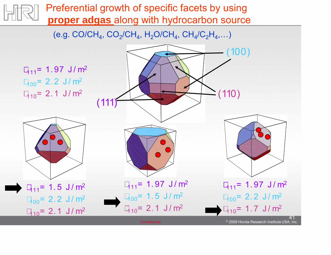
111= 1. 97 J / m2
100= 2. 2 J / m2
110= 2. 1 J / m2
(100)
(110)(111)
111= 1. 5 J / m2
100= 2. 2 J / m2
110= 2. 1 J / m2
111= 1. 97 J / m2
100= 1. 5 J / m2
110= 2. 1 J / m2
111= 1. 97 J / m2
100= 2. 2 J / m2
110= 1. 7 J / m2
Preferential growth of specific facets by using proper adgas along with hydrocarbon source
(e.g. CO/CH4, CO2/CH4, H2O/CH4, CH4/C2H4,…)
© 2009 Honda Research Institute USA, Inc.Confidential 42
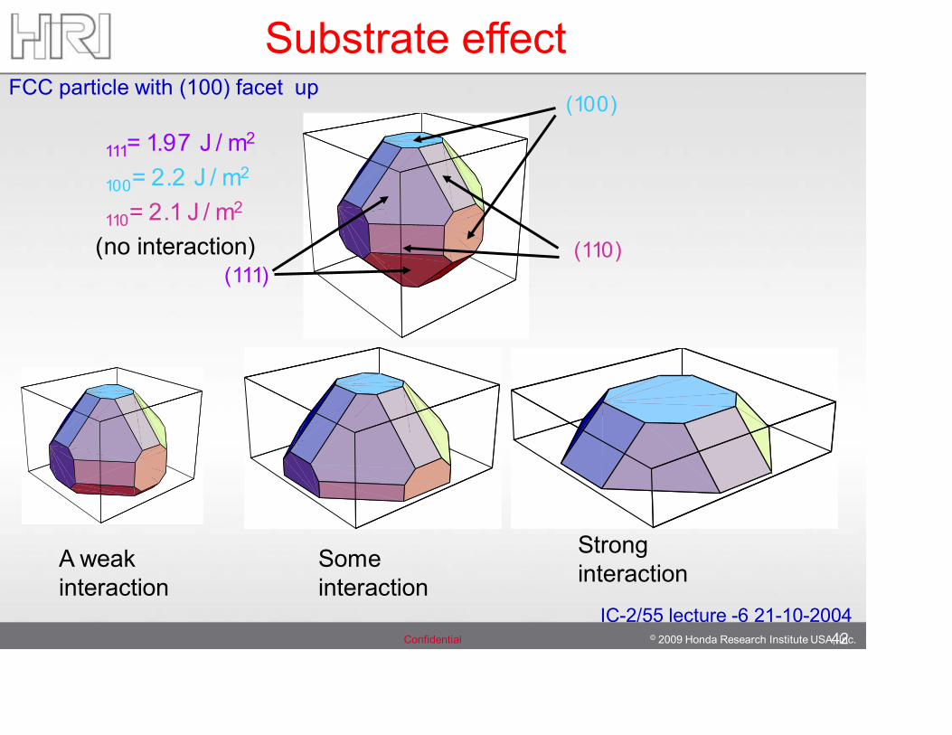
111= 1.97 J / m2
100= 2.2 J / m2
110= 2.1 J / m2
(no interaction)
(100)
(110)(111)
FCC particle with (100) facet up
A weak interaction
Some interaction
Strong interaction
Substrate effect
IC-2/55 lecture -6 21-10-2004
© 2009 Honda Research Institute USA, Inc.Confidential 43
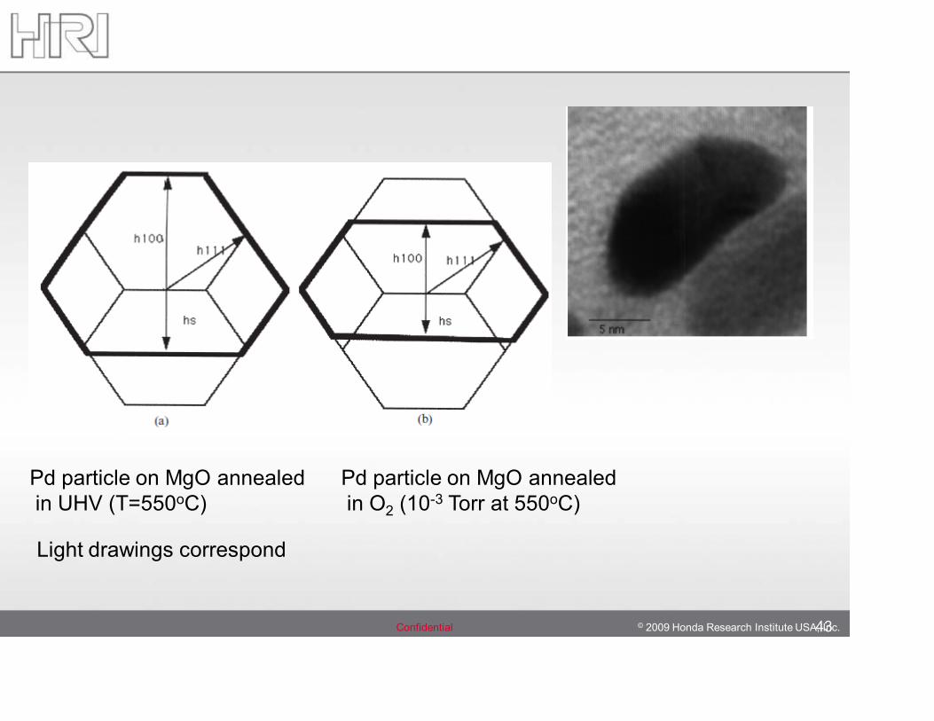
Pd particle on MgO annealedin UHV (T=550oC)
Pd particle on MgO annealedin O2 (10-3 Torr at 550oC)
Light drawings correspond