toward high-quality image communications: inverse problems ... · pdf filetoward high-quality...
TRANSCRIPT
Toward high-quality imagecommunications: inverse problems inimage processing
Cheolkon JungLicheng JiaoBing LiuHongtao QiTian Sun
Downloaded From: https://www.spiedigitallibrary.org/journals/Optical-Engineering on 5/23/2018 Terms of Use: https://www.spiedigitallibrary.org/terms-of-use
Toward high-quality image communications: inverseproblems in image processing
Cheolkon JungLicheng JiaoBing LiuHongtao QiTian SunXidian UniversityKey Lab of Intelligent Perception and Image
Understanding of Ministry of Education ofChina
Xi’an 710071, ChinaE-mail: [email protected]
Abstract. Recently, image communications are becoming increasinglypopular, and there is a growing need for consumers to be providedwith high-quality services. Although the image communication servicesalready exist over third-generation wireless networks, there are still obsta-cles that prevent high-quality image communications because of limitedbandwidth. Thus, more research is required to overcome the limited band-width of current communications systems and achieve high-quality imagereconstruction in real applications. From the point of view of image proces-sing, core technologies for high-quality image reconstruction are face hal-lucination and compression artifact reduction. The main interests ofconsumers are facial regions and several compression artifacts inevitablyoccur by compression; these two technologies are closely related toinverse problems in image processing. We review recent studies onface hallucination and compression artifact reduction, and provide an out-line of current research. Furthermore, we discuss practical considerationsand possible solutions to implement these two technologies in real mobileapplications. © 2012 Society of Photo-Optical Instrumentation Engineers (SPIE). [DOI: 10.1117/1.OE.51.10.100901]
Subject terms: compression artifact reduction; face hallucination; image communi-cations; image reconstruction; inverse problems in image processing..
Paper 120750V receivedMay 24, 2012; revised manuscript received Aug. 27, 2012;accepted for publication Aug. 30, 2012; published online Sep. 27, 2012.
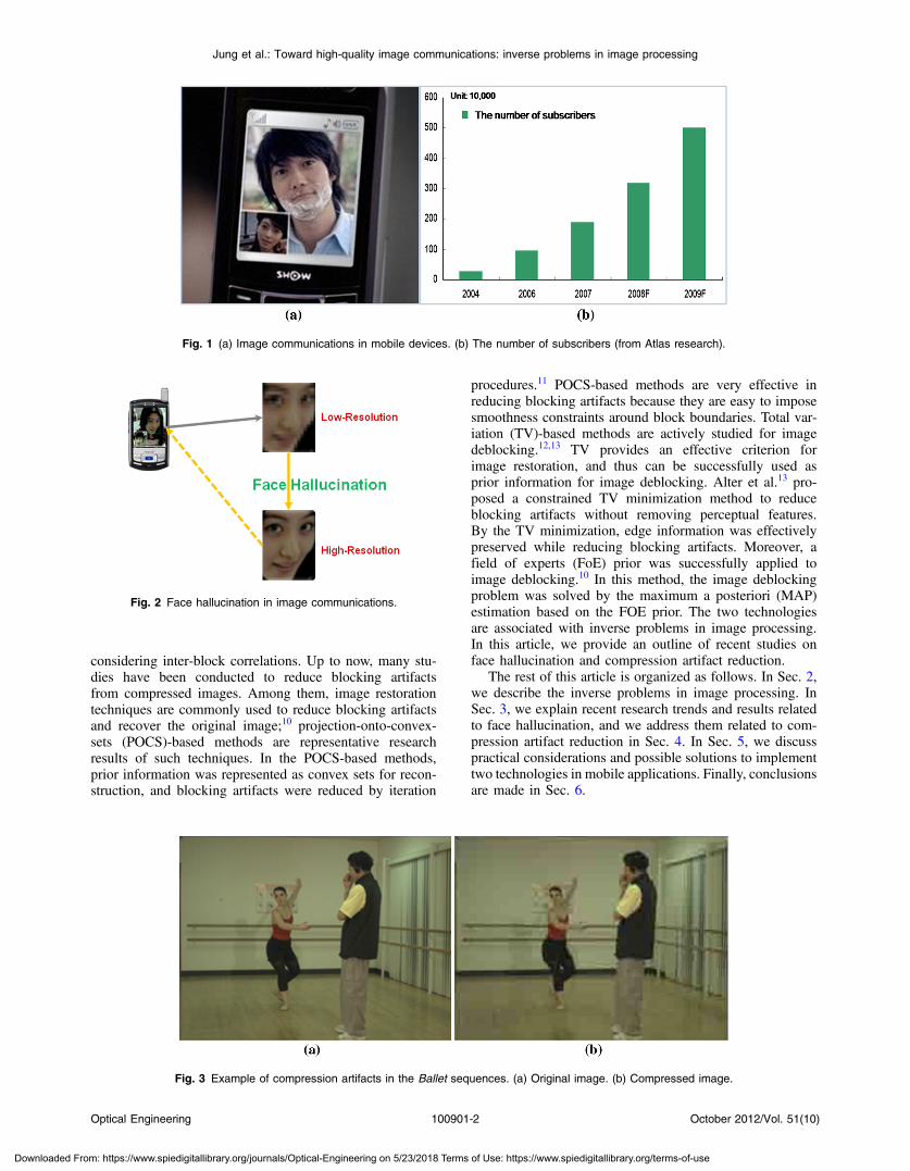
1 IntroductionWith advancements in mobile communication devices, tech-nology now allows people to communicate while looking ateach other’s face. This technology is also referred to asvideoconferencing and basically transmits images to a dis-play system so users can see each other while talking, asshown in Fig. 1(a). Many market analysts predict the numberof subscribers to image communication services grows expo-nentially every year because of lower mobile device pricesand aggressive marketing of communication companies, asshown in Fig. 1(b). As image communication services comeinto wide use, consumers want high-quality services.Although image communication services already existover third-generation (3G) wireless networks, such as thehigh-speed downlink packet access (HSDPA), there arestill obstacles that prevent high-quality communicationsbecause of limited bandwidth (maximum uploading anddownloading speeds are 14.4 and 5.76 Mbps, respectively).Consequently, more research is required to overcome thelimited bandwidth of current communications systems andachieve high-quality image reconstruction in mobile devices.In terms of image processing, core technologies for high-quality image reconstruction are face hallucination and com-pression artifact reduction.
Face hallucination technology, which is also referred asface super-resolution (SR), is very important for image com-munications because the main interests of consumers arefacial regions, as shown in Fig. 2. A number of relatedface hallucination methods have been proposed in recentyears. Among them, learning-based methods have received
much attention because they can achieve a high magnifica-tion factor and produce good SR results compared with othermethods. Baker and Kanade1,2 first introduced a face hallu-cination method which constructs the high frequency com-ponents from a parent-structure resorting to the training set.Wang and Tang3 presented a principal component analysis(PCA)-based face hallucination algorithm to globally inferthe high-resolution face image. Liu et al.4 developed atwo-step statistical modeling approach which integrates aglobal model and a local model corresponding to the com-mon and specific face characteristics, respectively. Althoughcomplicated probabilistic models are required in Liu et al.’smethod,4 the idea of the two-step approach became more andmore popular since then. Recently, a novel face hallucinationmethod based on position-patch has been proposed. Theposition-patch based method hallucinates the high resolution(HR) image patch using the same position image patches oftraining images.5–7 Thus, it is able to save computational timeand produce high-quality SR results compared to manifoldlearning-based methods.
With respect to the compression artifact reduction, severalcompression artifacts inevitably occur because of the loss ofhigh frequency components caused by lossy compressiontechniques such as H.264 or MPEG-4 (representative arti-fact: blocking artifact). They seriously degrade the picturequality and are annoying to viewers of the reconstructedimages as shown in Fig. 3.8,9 Accordingly, compression arti-fact reduction is also very important for image communica-tions. Blocking artifacts appear as grid noise along the blockboundaries because each block is transformed and quantizedindependently. Blocking artifacts occur because of the inde-pendent transform and quantization of each block without0091-3286/2012/$25.00 © 2012 SPIE
Optical Engineering 100901-1 October 2012/Vol. 51(10)
Optical Engineering 51(10), 100901 (October 2012) REVIEW
Downloaded From: https://www.spiedigitallibrary.org/journals/Optical-Engineering on 5/23/2018 Terms of Use: https://www.spiedigitallibrary.org/terms-of-use
considering inter-block correlations. Up to now, many stu-dies have been conducted to reduce blocking artifactsfrom compressed images. Among them, image restorationtechniques are commonly used to reduce blocking artifactsand recover the original image;10 projection-onto-convex-sets (POCS)-based methods are representative researchresults of such techniques. In the POCS-based methods,prior information was represented as convex sets for recon-struction, and blocking artifacts were reduced by iteration
procedures.11 POCS-based methods are very effective inreducing blocking artifacts because they are easy to imposesmoothness constraints around block boundaries. Total var-iation (TV)-based methods are actively studied for imagedeblocking.12,13 TV provides an effective criterion forimage restoration, and thus can be successfully used asprior information for image deblocking. Alter et al.13 pro-posed a constrained TV minimization method to reduceblocking artifacts without removing perceptual features.By the TV minimization, edge information was effectivelypreserved while reducing blocking artifacts. Moreover, afield of experts (FoE) prior was successfully applied toimage deblocking.10 In this method, the image deblockingproblem was solved by the maximum a posteriori (MAP)estimation based on the FOE prior. The two technologiesare associated with inverse problems in image processing.In this article, we provide an outline of recent studies onface hallucination and compression artifact reduction.
The rest of this article is organized as follows. In Sec. 2,we describe the inverse problems in image processing. InSec. 3, we explain recent research trends and results relatedto face hallucination, and we address them related to com-pression artifact reduction in Sec. 4. In Sec. 5, we discusspractical considerations and possible solutions to implementtwo technologies in mobile applications. Finally, conclusionsare made in Sec. 6.
Fig. 1 (a) Image communications in mobile devices. (b) The number of subscribers (from Atlas research).
Fig. 2 Face hallucination in image communications.
Fig. 3 Example of compression artifacts in the Ballet sequences. (a) Original image. (b) Compressed image.
Optical Engineering 100901-2 October 2012/Vol. 51(10)
Jung et al.: Toward high-quality image communications: inverse problems in image processing
Downloaded From: https://www.spiedigitallibrary.org/journals/Optical-Engineering on 5/23/2018 Terms of Use: https://www.spiedigitallibrary.org/terms-of-use
2 Inverse Problems in Image ProcessingInverse problems involve estimating parameters or data frominadequate observations; the observations are often noisyand contain incomplete information about the target para-meter or data due to physical limitations of the measurementdevices. Due to lack of sufficient information in the indirectobservations, solutions to inverse problems are usuallynonunique and challenging. That is, they are ill-posed pro-blems, and thus, some other reconstruction technologies arerequired to solve them including machine learning, Bayesianinference, convex optimization, sparse representation, and soon.14–16
Indeed, many problems in image processing can be repre-sented as inverse problems. They are modeled by relating theobserved image gðrÞ to the unknown original image fðrÞ. Ageneral form for the relation is as follows:14
gðrÞ ¼ ½Hf�ðrÞ þ nðrÞ; r ∈ R; (1)
where r represents the pixel position, R represents the wholesurface of gðrÞ, H is an operator representing the forwardproblem, and nðrÞ represents the errors (modeling uncer-tainty and observation errors). If we assume operator H islinear, we can write the observation model in a vector-matrixform as follows:
g ¼ Hf þ n; (2)
where g ¼ fgðrÞ; r ∈ Rg, f ¼ ffðrÞ; r ∈ Rg andn ¼ fnðrÞ; r ∈ Rg are vectors containing the observedimage pixel values, unknown original image pixel values,and observation errors, respectively; and H is a huge dimen-sional matrix whose elements are defined from H.
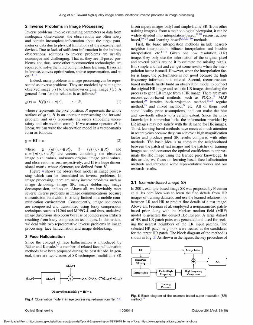
Figure 4 shows the observation model in image proces-sing which can be formulated as inverse problems. Inimage processing, there are many inverse problems such asimage denoising, image SR, image deblurring, imagedecompression, and so on. Above all, we inevitably meetseveral inverse problems in image communications becausetransmission bandwidth is strictly limited in a mobile com-munication environment. Consequently, image sequencesare compressed and transmitted using lossy compressiontechniques such as H.264 and MPEG-4, and thus, undesiredimage distortions also occur because of compression artifactsresulting from lossy compression techniques. In this article,we deal with two representative inverse problems in imageprocessing: face hallucination and image deblocking.
3 Face HallucinationSince the concept of face hallucination is introduced byBaker and Kanade,1,2 a number of related face hallucinationmethods have been proposed during the past decade. In gen-eral, there are two classes of SR techniques: multiframe SR
(from inputs images only) and single-frame SR (from othertraining images). From a methodological viewpoint, it can bewidely divided into interpolation-based,17,18 reconstruction-based,19–24 and learning-based3,6,7,25–30 methods.
First, the basic interpolation methods include nearest-neighbor interpolation, bilinear interpolation and bicubicinterpolation, etc.17,18 Given one low resolution (LR)image, they only use the information of the original pixeland several pixels around it to estimate the missing pixels.It is simple and fast and can get some results when the inter-polation factor is small. However, when the interpolation fac-tor is large, the performance is not good because the highfrequency information is missed. Second, reconstruction-based methods firstly build an observation model to connectthe original HR image and realistic LR image, simulating theprocess to get a LR image from a HR image. There are manyreconstruction-based methods, such as POCS,19 MAPmethod,20 iterative back-projection method,21,22 regularmethod,23 and mixed method,24 etc. All of them needsome locality prior assumptions, and can make the blurand saw-tooth effects to a certain extent. Since the priorknowledge is somewhat little, the information provided byLR images may not satisfy with the demand for HR images.Third, learning-based methods have received much attentionin recent years because they can achieve a high magnificationfactor and produce good SR results compared with othermethods. The basic idea is to compute the neighborhoodbetween the patch of test images and the patches of trainingimages set, and construct the optimal coefficients to approx-imate the HR image using the learned prior knowledge. Inthis article, we focus on learning-based face hallucinationmethods and introduce some representative works and ourresearch results.
3.1 Example-Based Image SR
In 2001, example-based image SR was proposed by Freemanet al. Its core idea was to learn the fine details from HRimages of training datasets, and use the learned relationshipsbetween LR and HR to predict fine details of a test image.Above all, Freeman et al. employed a nonparametric patch-based prior along with the Markov random field (MRF)model to generate the desired HR images. A large datasetof HR and LR patch pairs was generated and used for seek-ing the nearest neighbors of the LR input patches. Theselected HR patch neighbors were treated as the candidatesfor the target HR patch. The block diagram of the method isshown in Fig. 5. As shown in the figure, the key procedure of
Fig. 4 Observation model in image processing, redrawn from Ref. 14.Fig. 5 Block diagram of the example-based super resolution (SR)method.25
Optical Engineering 100901-3 October 2012/Vol. 51(10)
Jung et al.: Toward high-quality image communications: inverse problems in image processing
Downloaded From: https://www.spiedigitallibrary.org/journals/Optical-Engineering on 5/23/2018 Terms of Use: https://www.spiedigitallibrary.org/terms-of-use
this method is to predict the missing high frequencies usingthe training datasets.
3.2 Neighbor-Embedding Based Image SR
In 2004, Chang et al. proposed a novel method for solvingsingle-image SR problems. In this method, given an LRimage as input, a set of training examples were used torecover its HR counterpart. While this formulationresembled other learning-based methods for SR, this methodwas inspired by manifold learning-based methods, particu-larly locally linear embedding (LLE). More specifically,small image patches in LR and HR images formed manifoldswith similar local geometry in two distinct feature spaces.Then, multiple nearest neighbors were selected in the featurespace, and SR images were reconstructed by the correspond-ing HR patches of the nearest neighbors. Since then, thismethod has been extensively applied to solving image SRproblems including face hallucination.
3.3 PCA-Based Face Hallucination
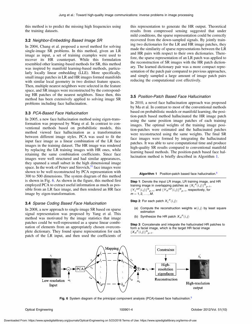
In 2005, a new face hallucination method using eigen-trans-formation was proposed by Wang et al. In contrast to con-ventional methods based on probabilistic models, thismethod viewed face hallucination as a transformationbetween different image styles. PCA was used to fit theinput face image as a linear combination of the LR faceimages in the training dataset. The HR image was renderedby replacing the LR training images with HR ones, whileretaining the same combination coefficients. Since faceimages were well structured and had similar appearances,they spanned a small subset in the high dimensional imagespace. In the work of Penev and Sirovich,31 face images wereshown to be well reconstructed by PCA representation with300 to 500 dimensions. The system diagram of this methodis shown in Fig. 6. As shown in the figure, this method firstemployed PCA to extract useful information as much as pos-sible from an LR face image, and then rendered an HR faceimage by eigen-transformation.
3.4 Sparse Coding Based Face Hallucination
In 2008, a new approach to single-image SR based on sparsesignal representation was proposed by Yang et al. Thismethod was motivated by the image statistics that imagepatches could be well-represented as a sparse linear combi-nation of elements from an appropriately chosen overcom-plete dictionary. They found sparse representation for eachpatch of the LR input, and then used the coefficients of
this representation to generate the HR output. Theoreticalresults from compressed sensing suggested that undermild conditions, the sparse representation could be correctlyrecovered from the down-sampled signals. By jointly train-ing two dictionaries for the LR and HR image patches, theymade the similarity of sparse representations between the LRand HR pairs with respect to their own dictionaries. There-fore, the sparse representation of an LR patch was applied tothe reconstruction of SR images with the HR patch diction-ary. The learned dictionary pair was a more compact repre-sentation of the patch pair compared to previous approaches,and simply sampled a large amount of image patch pairsreducing the computational cost effectively.
3.5 Position-Patch Based Face Hallucination
In 2010, a novel face hallucination approach was proposedby Ma et al. In contrast to most of the conventional methodsbased on probabilistic models or manifold learning, the posi-tion-patch based method hallucinated the HR image patchusing the same position image patches of each trainingimages. The optimal weights of the training image posi-tion-patches were estimated and the hallucinated patcheswere reconstructed using the same weights. The final SRface images were formed by integrating the hallucinatedpatches. It was able to save computational time and producehigh-quality SR results compared to conventional manifoldlearning based methods. The position-patch based face hal-lucination method is briefly described in Algorithm 1.
Fig. 6 System diagram of the prinicipal component analysis (PCA)-based face hallucination.3
Algorithm 1 Position-patch based face hallucination.5
Step 1: Denote the input LR image, LR training image, and HRtraining image in overlapping patches as fXL
P ði ; jÞgNp¼1,fYL
mP ði ; jÞgNp¼1, and fYHmP ði ; jÞgNp¼1, respectively, for
m ¼ 1;2; : : : ; M .
Step 2: For each patch XLP ði ; jÞ:
(a) Compute the reconstruction weights wði ; jÞ by least squareestimation
(b) Synthesize the HR patch XHP ði ; jÞ
Step 3: Concatenate and integrate the hallucinated HR patches toform a facial image, which is the target HR facial imagefXH
P ði ; jÞgNp¼1.
Optical Engineering 100901-4 October 2012/Vol. 51(10)
Jung et al.: Toward high-quality image communications: inverse problems in image processing
Downloaded From: https://www.spiedigitallibrary.org/journals/Optical-Engineering on 5/23/2018 Terms of Use: https://www.spiedigitallibrary.org/terms-of-use
3.6 Convex-Optimization-Based Face Hallucination
Inspired by the position-patch based face hallucinationmethod, a new convex optimization based face hallucinationmethod is proposed. The position-patch based method hasemployed least square estimation to get the optimal weightsfor face hallucination; however, the least square estimationapproach can provide biased solutions when the number ofthe training position-patches is much larger than the dimen-sion of the patch. To overcome this problem, we make use ofconstrained convex optimization instead of least square esti-mation to obtain the optimal weights for face hallucination.The optimal weights (w) are computed by solving the follow-ing convex optimization problem:
minw
kwk1 subject to kXPL − YP
L · wk22 ≤ ε; (3)
where YLP is a column matrix of the training patches
YLmPði; jÞ for m ¼ 1; 2; : : : ;M; and ε is a error tolerance.
Consequently, the hallucinated HR patch XHPði; jÞ is
obtained by:
XPHði; jÞ ¼
XMm¼1
YmPH ði; jÞ · wmði; jÞ: (4)
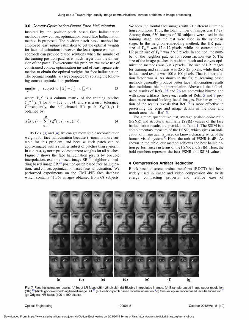
By Eqs. (3) and (4), we can get more stable reconstructionweights for face hallucination because l1-norm is more sui-table for this problem, and because each patch can beapproximated with a smaller subset of patches than l2-norm.In contrast, l2-norm provides nonzero weights for all patches.Figure 7 shows the face hallucination results by bi-cubicinterpolation, example-based image SR,25 neighbor-embed-ding based image SR,26 position-patch based face hallucina-tion,5 and convex optimization based face hallucination.7 Weperformed experiments on the CMU-PIE face databasewhich contains 41,368 images obtained from 68 subjects.
We took the frontal face images with 21 different illumina-tion conditions. Thus, the total number of images was 1,428.Among them, 630 images of 30 subjects were used in thetraining stage, and the rest were used in the synthesisstage. In the neighbor-embedding method, the HR patchsize of YH
m was 12 × 12 pixels, while the correspondingLR patch size of YL
m was 3 × 3 pixels. In addition, the num-ber of the neighbor patches for reconstruction was 5. Thesize of the image patches in position-patch and convex opti-mization methods was 3 × 3 pixels. The size of LR imagesfor training and synthesis was 25 × 25 pixels, while that ofhallucinated results was 100 × 100 pixels. That is, interpola-tion factor was 4. As shown in the figure, learning basedmethods generally produce better face hallucination resultsthan traditional bicubic interpolation. Above all, the halluci-nated results of Refs. 25 and 26 are somewhat blurred andwith some artifacts; however, results of Refs. 5 and 7 pro-duce more natural looking facial images. Further examina-tion of the results reveals that Ref. 7 is more effective inpreserving the edge and image details in the nose andmouth areas than Ref. 5.
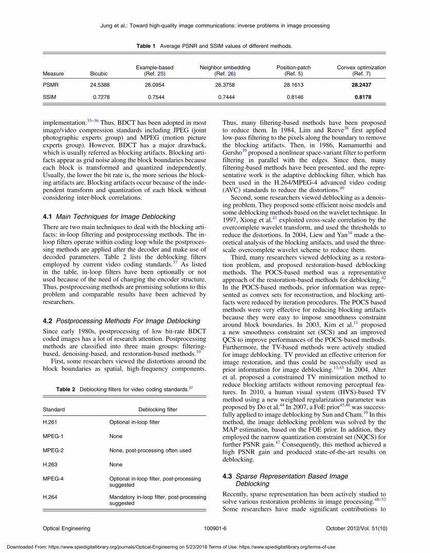
For a more quantitative test, average peak-to-noise ratio(PSNR) and structural similarity (SSIM) values of the facehallucination results are provided in Table 1. The SSIM is acomplementary measure of the PSNR, which gives an indi-cation of image quality based on known characteristics of thehuman visual system.32 Here, the unit of PSNR is dB. Asshown in the table, our method achieves the best hallucina-tion performances in terms of the PSNR and SSIM. Here, thebold numbers represent the best PSNR and SSIM values.
4 Compression Artifact ReductionBlock-based discrete cosine transform (BDCT) has beenwidely used in image and video compression due to itsenergy compacting property and relative ease of
Fig. 7 Face hallucination results. (a) Input LR faces (25 × 25 pixels). (b) Bicubic interpolated images. (c) Example-based image super resolution(SR).25 (d) Neighbor-embedding based image SR.26 (e) Position-patch based face hallucination.5 (f) Convex optimization based face hallucination.7
(g) Original HR faces (100 × 100 pixels).
Optical Engineering 100901-5 October 2012/Vol. 51(10)
Jung et al.: Toward high-quality image communications: inverse problems in image processing
Downloaded From: https://www.spiedigitallibrary.org/journals/Optical-Engineering on 5/23/2018 Terms of Use: https://www.spiedigitallibrary.org/terms-of-use
implementation.33–36 Thus, BDCT has been adopted in mostimage/video compression standards including JPEG (jointphotographic experts group) and MPEG (motion pictureexperts group). However, BDCT has a major drawback,which is usually referred as blocking artifacts. Blocking arti-facts appear as grid noise along the block boundaries becauseeach block is transformed and quantized independently.Usually, the lower the bit rate is, the more serious the block-ing artifacts are. Blocking artifacts occur because of the inde-pendent transform and quantization of each block withoutconsidering inter-block correlations.
4.1 Main Techniques for Image Deblocking
There are two main techniques to deal with the blocking arti-facts: in-loop filtering and postprocessing methods. The in-loop filters operate within coding loop while the postproces-sing methods are applied after the decoder and make use ofdecoded parameters. Table 2 lists the deblocking filtersemployed by current video coding standards.37 As listedin the table, in-loop filters have been optionally or notused because of the need of changing the encoder structure.Thus, postprocessing methods are promising solutions to thisproblem and comparable results have been achieved byresearchers.
4.2 Postprocessing Methods For Image Deblocking
Since early 1980s, postprocessing of low bit-rate BDCTcoded images has a lot of research attention. Postprocessingmethods are classified into three main groups: filtering-based, denoising-based, and restoration-based methods.10
First, some researchers viewed the distortions around theblock boundaries as spatial, high-frequency components.
Thus, many filtering-based methods have been proposedto reduce them. In 1984, Lim and Reeve38 first appliedlow-pass filtering to the pixels along the boundary to removethe blocking artifacts. Then, in 1986, Ramamurthi andGersho39 proposed a nonlinear space-variant filter to performfiltering in parallel with the edges. Since then, manyfiltering-based methods have been presented, and the repre-sentative work is the adaptive deblocking filter, which hasbeen used in the H.264/MPEG-4 advanced video coding(AVC) standards to reduce the distortions.40
Second, some researchers viewed deblocking as a denois-ing problem. They proposed some efficient noise models andsome deblocking methods based on the wavelet technique. In1997, Xiong et al.41 exploited cross-scale correlation by theovercomplete wavelet transform, and used the thresholds toreduce the distortions. In 2004, Liew and Yan34 made a the-oretical analysis of the blocking artifacts, and used the three-scale overcomplete wavelet scheme to reduce them.
Third, many researchers viewed deblocking as a restora-tion problem, and proposed restoration-based deblockingmethods. The POCS-based method was a representativeapproach of the restoration-based methods for deblocking.42
In the POCS-based methods, prior information was repre-sented as convex sets for reconstruction, and blocking arti-facts were reduced by iteration procedures. The POCS basedmethods were very effective for reducing blocking artifactsbecause they were easy to impose smoothness constraintaround block boundaries. In 2003, Kim et al.11 proposeda new smoothness constraint set (SCS) and an improvedQCS to improve performances of the POCS-based methods.Furthermore, the TV-based methods were actively studiedfor image deblocking. TV provided an effective criterion forimage restoration, and thus could be successfully used asprior information for image deblocking.13,43 In 2004, Alteret al. proposed a constrained TV minimization method toreduce blocking artifacts without removing perceptual fea-tures. In 2010, a human visual system (HVS)-based TVmethod using a new weighted regularization parameter wasproposed by Do et al.44 In 2007, a FoE prior45,46 was success-fully applied to image deblocking by Sun and Cham.10 In thismethod, the image deblocking problem was solved by theMAP estimation, based on the FOE prior. In addition, theyemployed the narrow quantization constraint set (NQCS) forfurther PSNR gain.47 Consequently, this method achieved ahigh PSNR gain and produced state-of-the-art results ondeblocking.
4.3 Sparse Representation Based ImageDeblocking
Recently, sparse representation has been actively studied tosolve various restoration problems in image processing.48–52
Some researchers have made significant contributions to
Table 1 Average PSNR and SSIM values of different methods.
Measure BicubicExample-based
(Ref. 25)Neighbor embedding
(Ref. 26)Position-patch
(Ref. 5)Convex optimization
(Ref. 7)
PSMR 24.5388 26.0954 26.3758 28.1613 28.2437
SSIM 0.7278 0.7544 0.7444 0.8146 0.8178
Table 2 Deblocking filters for video coding standards.37
Standard Deblocking filter
H.261 Optional in-loop filter
MPEG-1 None
MPEG-2 None, post-processing often used
H.263 None
MPEG-4 Optional in-loop filter, post-processingsuggested
H.264 Mandatory in-loop filter, post-processingsuggested
Optical Engineering 100901-6 October 2012/Vol. 51(10)
Jung et al.: Toward high-quality image communications: inverse problems in image processing
Downloaded From: https://www.spiedigitallibrary.org/journals/Optical-Engineering on 5/23/2018 Terms of Use: https://www.spiedigitallibrary.org/terms-of-use
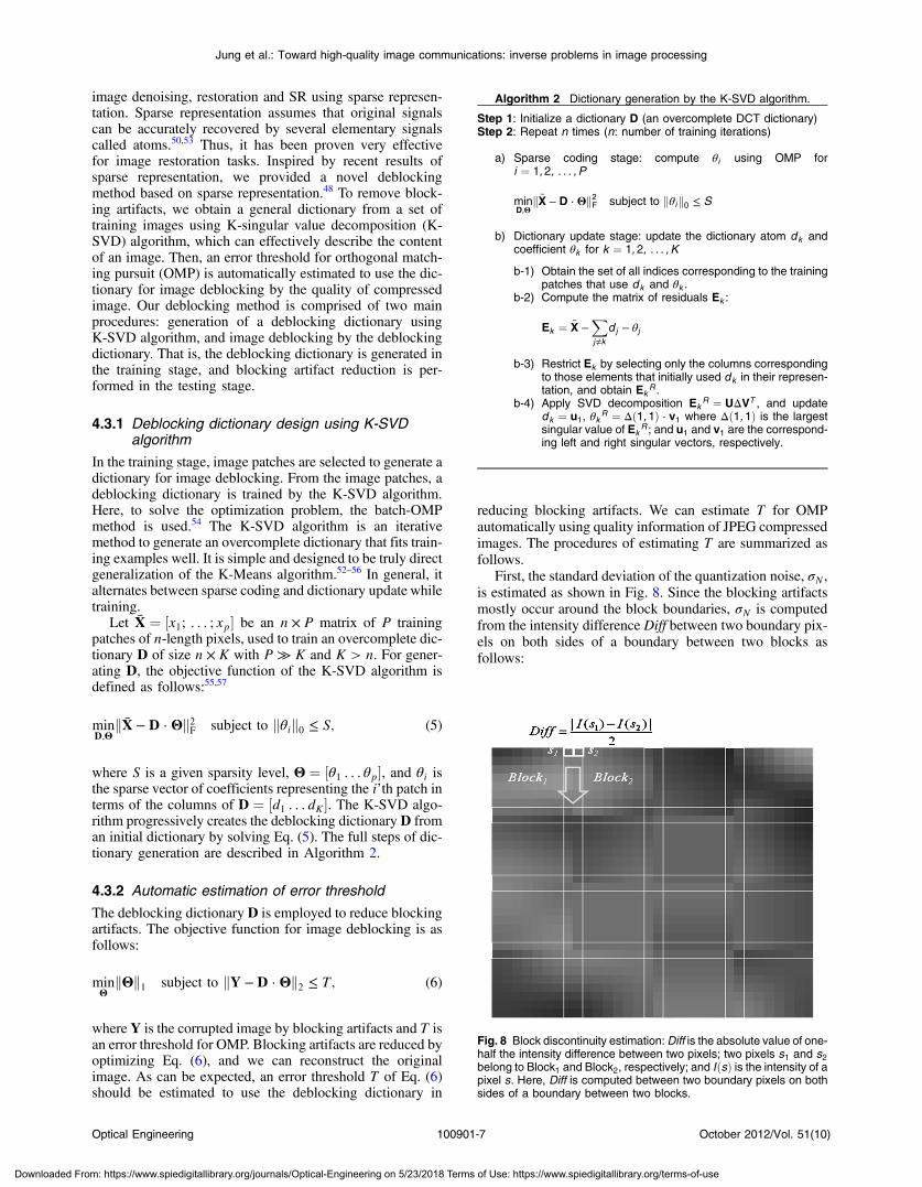
image denoising, restoration and SR using sparse represen-tation. Sparse representation assumes that original signalscan be accurately recovered by several elementary signalscalled atoms.50,53 Thus, it has been proven very effectivefor image restoration tasks. Inspired by recent results ofsparse representation, we provided a novel deblockingmethod based on sparse representation.48 To remove block-ing artifacts, we obtain a general dictionary from a set oftraining images using K-singular value decomposition (K-SVD) algorithm, which can effectively describe the contentof an image. Then, an error threshold for orthogonal match-ing pursuit (OMP) is automatically estimated to use the dic-tionary for image deblocking by the quality of compressedimage. Our deblocking method is comprised of two mainprocedures: generation of a deblocking dictionary usingK-SVD algorithm, and image deblocking by the deblockingdictionary. That is, the deblocking dictionary is generated inthe training stage, and blocking artifact reduction is per-formed in the testing stage.
4.3.1 Deblocking dictionary design using K-SVDalgorithm
In the training stage, image patches are selected to generate adictionary for image deblocking. From the image patches, adeblocking dictionary is trained by the K-SVD algorithm.Here, to solve the optimization problem, the batch-OMPmethod is used.54 The K-SVD algorithm is an iterativemethod to generate an overcomplete dictionary that fits train-ing examples well. It is simple and designed to be truly directgeneralization of the K-Means algorithm.52–56 In general, italternates between sparse coding and dictionary update whiletraining.
Let X̄ ¼ ½x1; : : : ; xp� be an n × P matrix of P trainingpatches of n-length pixels, used to train an overcomplete dic-tionary D of size n × K with P ≫ K and K > n. For gener-ating D, the objective function of the K-SVD algorithm isdefined as follows:55,57
minD;Θ
kX̄ − D · Θk2F subject to kθik0 ≤ S; (5)
where S is a given sparsity level, Θ ¼ ½θ1 : : : θp�, and θi isthe sparse vector of coefficients representing the i’th patch interms of the columns of D ¼ ½d1 : : : dK�. The K-SVD algo-rithm progressively creates the deblocking dictionary D froman initial dictionary by solving Eq. (5). The full steps of dic-tionary generation are described in Algorithm 2.
4.3.2 Automatic estimation of error threshold
The deblocking dictionary D is employed to reduce blockingartifacts. The objective function for image deblocking is asfollows:
minΘ
kΘk1 subject to kY − D · Θk2 ≤ T; (6)
where Y is the corrupted image by blocking artifacts and T isan error threshold for OMP. Blocking artifacts are reduced byoptimizing Eq. (6), and we can reconstruct the originalimage. As can be expected, an error threshold T of Eq. (6)should be estimated to use the deblocking dictionary in
reducing blocking artifacts. We can estimate T for OMPautomatically using quality information of JPEG compressedimages. The procedures of estimating T are summarized asfollows.
First, the standard deviation of the quantization noise, σN ,is estimated as shown in Fig. 8. Since the blocking artifactsmostly occur around the block boundaries, σN is computedfrom the intensity difference Diff between two boundary pix-els on both sides of a boundary between two blocks asfollows:
Algorithm 2 Dictionary generation by the K-SVD algorithm.
Step 1: Initialize a dictionary D (an overcomplete DCT dictionary)Step 2: Repeat n times (n: number of training iterations)
a) Sparse coding stage: compute θi using OMP fori ¼ 1;2; : : : ; P
minD;Θ
kX̄ − D · Θk2F subject to kθik0 ≤ S
b) Dictionary update stage: update the dictionary atom dk andcoefficient θk for k ¼ 1; 2; : : : ; K
b-1) Obtain the set of all indices corresponding to the trainingpatches that use dk and θk .
b-2) Compute the matrix of residuals Ek :
Ek ¼ X̄ −Xj≠k
d j − θj
b-3) Restrict Ek by selecting only the columns correspondingto those elements that initially used dk in their represen-tation, and obtain Ek
R .b-4) Apply SVD decomposition Ek
R ¼ UΔVT , and updatedk ¼ u1, θk R ¼ Δð1;1Þ · v1 where Δð1; 1Þ is the largestsingular value of Ek
R ; and u1 and v1 are the correspond-ing left and right singular vectors, respectively.
Fig. 8 Block discontinuity estimation:Diff is the absolute value of one-half the intensity difference between two pixels; two pixels s1 and s2belong to Block1 and Block2, respectively; and IðsÞ is the intensity of apixel s. Here, Diff is computed between two boundary pixels on bothsides of a boundary between two blocks.
Optical Engineering 100901-7 October 2012/Vol. 51(10)
Jung et al.: Toward high-quality image communications: inverse problems in image processing
Downloaded From: https://www.spiedigitallibrary.org/journals/Optical-Engineering on 5/23/2018 Terms of Use: https://www.spiedigitallibrary.org/terms-of-use
Diff ¼ jIðs1Þ − Iðs2Þj2
; (7)
where Diff is the absolute value of one-half the intensity dif-ference between two pixels, s1 and s2. In computing Diff,only horizontal or vertical block discontinuities are consid-ered as mentioned in Ref. 34. In the figure, pixels s1 and s2belong to Block1 and Block2, respectively; IðsÞ is the inten-sity of a pixel s. Accordingly, we compute σN of the com-pressed blocky image from Diff.
Then, T is computed based on σN . In the previous worksfor image denoising,34,53,57 Told is obtained by the followingequation:
Told ¼ C · σN: (8)
Here, the noise gain C is set to 1.15. In the JPEG codingstandard, the most important parameter is the quality q,
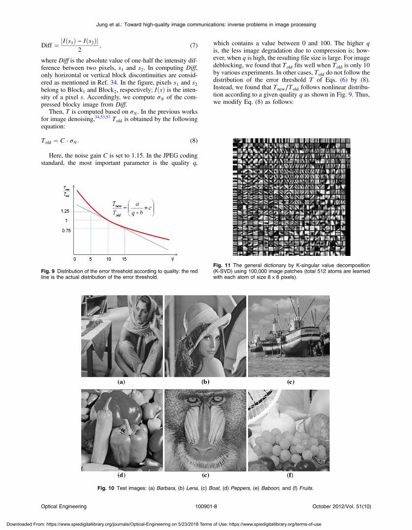
which contains a value between 0 and 100. The higher qis, the less image degradation due to compression is; how-ever, when q is high, the resulting file size is large. For imagedeblocking, we found that Told fits well when Told is only 10by various experiments. In other cases, Told do not follow thedistribution of the error threshold T of Eqs. (6) by (8).Instead, we found that Tnew∕Told follows nonlinear distribu-tion according to a given quality q as shown in Fig. 9. Thus,we modify Eq. (8) as follows:
Fig. 9 Distribution of the error threshold according to quality: the redline is the actual distribution of the error threshold.
Fig. 10 Test images: (a) Barbara, (b) Lena, (c) Boat, (d) Peppers, (e) Baboon, and (f) Fruits.
Fig. 11 The general dictionary by K-singular value decomposition(K-SVD) using 100,000 image patches (total 512 atoms are learnedwith each atom of size 8 × 8 pixels).
Optical Engineering 100901-8 October 2012/Vol. 51(10)
Jung et al.: Toward high-quality image communications: inverse problems in image processing
Downloaded From: https://www.spiedigitallibrary.org/journals/Optical-Engineering on 5/23/2018 Terms of Use: https://www.spiedigitallibrary.org/terms-of-use
Tnew ¼ Told ·
�a
qþ bþ c
�¼ C · σN ·
�a
qþ bþ c
�; (9)
where a, b, and c are the control parameters, and their appro-priate values are adjusted by experiments. Here, a, b, and care set to be 20, 10, and 0, respectively. Consequently, theerror threshold for OMP is computed by Tnew of Eq. (6), andused to solve Eq. (3). As a result, we get deblocked results ofJPEG compressed images by the learned dictionary D.
As shown in Fig. 10, six typical images were used for thetests, Barbara, Lena, Boat, Peppers, Baboon, and Fruits,whose sizes were 512 × 512 pixels. In the training stage,total 91 natural images provided by the Yang et al.’swork51 were used to generate a general dictionary. Dictionary
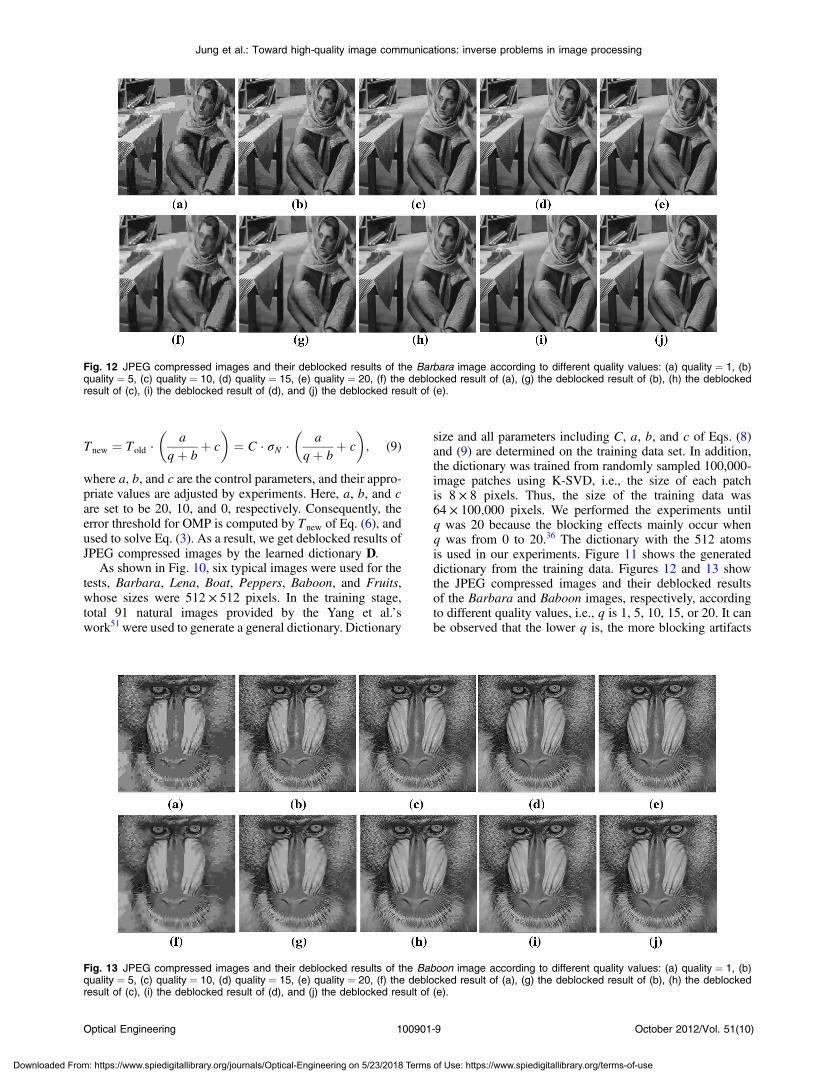
size and all parameters including C, a, b, and c of Eqs. (8)and (9) are determined on the training data set. In addition,the dictionary was trained from randomly sampled 100,000-image patches using K-SVD, i.e., the size of each patchis 8 × 8 pixels. Thus, the size of the training data was64 × 100;000 pixels. We performed the experiments untilq was 20 because the blocking effects mainly occur whenq was from 0 to 20.36 The dictionary with the 512 atomsis used in our experiments. Figure 11 shows the generateddictionary from the training data. Figures 12 and 13 showthe JPEG compressed images and their deblocked resultsof the Barbara and Baboon images, respectively, accordingto different quality values, i.e., q is 1, 5, 10, 15, or 20. It canbe observed that the lower q is, the more blocking artifacts
Fig. 12 JPEG compressed images and their deblocked results of the Barbara image according to different quality values: (a) quality ¼ 1, (b)quality ¼ 5, (c) quality ¼ 10, (d) quality ¼ 15, (e) quality ¼ 20, (f) the deblocked result of (a), (g) the deblocked result of (b), (h) the deblockedresult of (c), (i) the deblocked result of (d), and (j) the deblocked result of (e).
Fig. 13 JPEG compressed images and their deblocked results of the Baboon image according to different quality values: (a) quality ¼ 1, (b)quality ¼ 5, (c) quality ¼ 10, (d) quality ¼ 15, (e) quality ¼ 20, (f) the deblocked result of (a), (g) the deblocked result of (b), (h) the deblockedresult of (c), (i) the deblocked result of (d), and (j) the deblocked result of (e).
Optical Engineering 100901-9 October 2012/Vol. 51(10)
Jung et al.: Toward high-quality image communications: inverse problems in image processing
Downloaded From: https://www.spiedigitallibrary.org/journals/Optical-Engineering on 5/23/2018 Terms of Use: https://www.spiedigitallibrary.org/terms-of-use
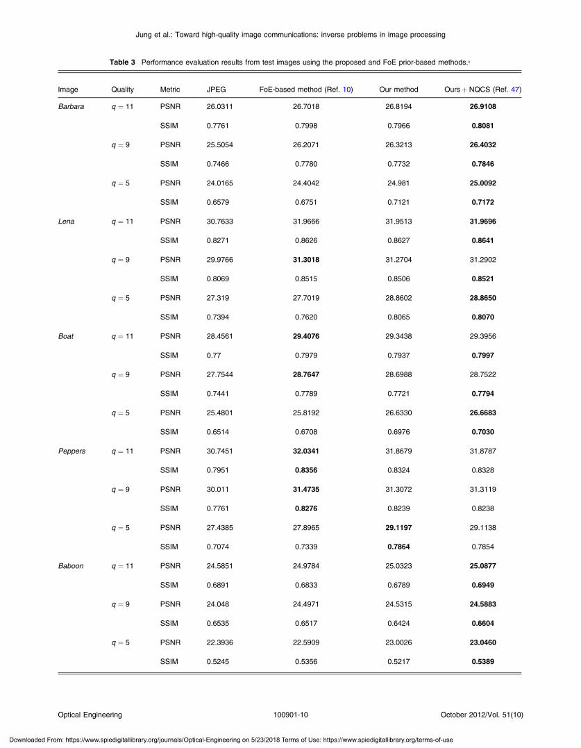
Table 3 Performance evaluation results from test images using the proposed and FoE prior-based methods.a
Image Quality Metric JPEG FoE-based method (Ref. 10) Our method Oursþ NQCS (Ref. 47)
Barbara q ¼ 11 PSNR 26.0311 26.7018 26.8194 26.9108
SSIM 0.7761 0.7998 0.7966 0.8081
q ¼ 9 PSNR 25.5054 26.2071 26.3213 26.4032
SSIM 0.7466 0.7780 0.7732 0.7846
q ¼ 5 PSNR 24.0165 24.4042 24.981 25.0092
SSIM 0.6579 0.6751 0.7121 0.7172
Lena q ¼ 11 PSNR 30.7633 31.9666 31.9513 31.9696
SSIM 0.8271 0.8626 0.8627 0.8641
q ¼ 9 PSNR 29.9766 31.3018 31.2704 31.2902
SSIM 0.8069 0.8515 0.8506 0.8521
q ¼ 5 PSNR 27.319 27.7019 28.8602 28.8650
SSIM 0.7394 0.7620 0.8065 0.8070
Boat q ¼ 11 PSNR 28.4561 29.4076 29.3438 29.3956
SSIM 0.77 0.7979 0.7937 0.7997
q ¼ 9 PSNR 27.7544 28.7647 28.6988 28.7522
SSIM 0.7441 0.7789 0.7721 0.7794
q ¼ 5 PSNR 25.4801 25.8192 26.6330 26.6683
SSIM 0.6514 0.6708 0.6976 0.7030
Peppers q ¼ 11 PSNR 30.7451 32.0341 31.8679 31.8787
SSIM 0.7951 0.8356 0.8324 0.8328
q ¼ 9 PSNR 30.011 31.4735 31.3072 31.3119
SSIM 0.7761 0.8276 0.8239 0.8238
q ¼ 5 PSNR 27.4385 27.8965 29.1197 29.1138
SSIM 0.7074 0.7339 0.7864 0.7854
Baboon q ¼ 11 PSNR 24.5851 24.9784 25.0323 25.0877
SSIM 0.6891 0.6833 0.6789 0.6949
q ¼ 9 PSNR 24.048 24.4971 24.5315 24.5883
SSIM 0.6535 0.6517 0.6424 0.6604
q ¼ 5 PSNR 22.3936 22.5909 23.0026 23.0460
SSIM 0.5245 0.5356 0.5217 0.5389
Optical Engineering 100901-10 October 2012/Vol. 51(10)
Jung et al.: Toward high-quality image communications: inverse problems in image processing
Downloaded From: https://www.spiedigitallibrary.org/journals/Optical-Engineering on 5/23/2018 Terms of Use: https://www.spiedigitallibrary.org/terms-of-use

occur along block boundaries in the compressed images.This is because transform coefficients of blocks are quan-tized independently in BDCT based image compression.As can be seen in (a)-(e) of the figures, the blocking artifactsare degrading the quality of picture seriously. In addition, theblocking artifacts are remarkably reduced as the qualityincreases. In the figures, (f)-(j) show the reduction resultsof the blocking artifacts by the proposed method. It canbe observed that the proposed method suppresses the block-ing artifacts efficiently and improves the picture quality,especially along block boundaries where the block disconti-nuities are severe.
To provide more reliable performance evaluation of theresults, we compare our method with the latest state-of-the-art one which is based on the FoE prior.10 It has beenreported that the method has achieved the best deblockedresults in terms of PSNR. As evaluation metrics, thePSNR and SSIM are considered to measure the quality ofthe estimated images. To simulate various types of BDCTcompression, three quantization tables, usually denoted asQ1, Q2, and Q3, have been commonly used by manyresearchers.10,34 The Q1, Q2, and Q3 tables correspond toa medium to high compression level, similar to what can
be obtained by using JPEG with q ¼ 11, q ¼ 9, andq ¼ 5, respectively.9 Accordingly, in our experiments, thevalues of q are used instead of the quantization tables whenthe performance of our method is evaluated because ourmethod is based on the quality information. Table 3 liststhe PSNR and SSIM values of the deblocked results obtainedby the FoE prior-based method and ours. In the FOE prior-based method,10 the FoE prior captures the statistics of nat-ural images, and thus, has been effectively employed forimage denoising and inpainting.45,46 The FOE prior hasbeen successfully applied to deblocking of BDCT com-pressed images.10 We have obtained the corresponding soft-ware for evaluation at http://www.cs.brown.edu/ dqsun/research/software.html. In the experiments, the FoE filtersize is 5 × 5 pixels and the maximum number of iterationsis 200. In the FoE prior-based method,10 the narrow quanti-zation constraint set (NQCS)47 have been used for the higherPSNR gain of deblocked results, and thus we also report theimproved PSNR values by NQCS (see the 7th column).Combined with the NQCS method,47 our method generallyachieves the best PSNR and SSIM results about the testimages. In the table, the bold numbers represent the bestPSNR and SSIM values of each image at each quality.
Table 3 (Continued).
Image Quality Metric JPEG FoE-based method (Ref. 10) Our method Oursþ NQCS (Ref. 47)
Fruits q ¼ 11 PSNR 30.1973 31.4000 31.3322 31.3977
SSIM 0.7961 0.8391 0.8378 0.8414
q ¼ 9 PSNR 29.4625 30.7641 30.7147 30.7725
SSIM 0.7758 0.8275 0.8262 0.8294
q ¼ 5 PSNR 27.0479 27.5133 28.5934 28.623
SSIM 0.7043 0.7297 0.7819 0.7829
aIn the FoE prior-based method,10 the results combined with the NQCS method47 are reported. The bold numbers represent the best PSNR andSSIM values of each image at each quality. The unit of PSNR is dB.
Table 4 Mobile phone trends in 5-year intervals.58
Year 1995 2000 2005 2010 2015
Cellular generation 2 G 2.5-3 G 3.5 G Pre-4 G 4 G
Cellular standards GSM GPRSUMTS HSPA HSPALTE LTELTE-A
Downlink bitrate (Mb/s) 0.01 0.1 1 10 100
Battery capacity (Wh) 1 2 3 4 5
Phone CPU Clock (MHz) 20 100 200 500 1000
Phone CPU Power (W) 0.05 0.05 0.1 0.2 0.3
Workload (GOPS) 0.1 1 10 100 1000
#Programmable cores 1 2 4 8 16
Optical Engineering 100901-11 October 2012/Vol. 51(10)
Jung et al.: Toward high-quality image communications: inverse problems in image processing
Downloaded From: https://www.spiedigitallibrary.org/journals/Optical-Engineering on 5/23/2018 Terms of Use: https://www.spiedigitallibrary.org/terms-of-use
5 Practical Considerations for Mobile ApplicationsCurrently, high-end mobile phones, which are usuallyreferred to as smartphones, support multiple radio standardsand a rich suite of applications including advanced radio,audio, video, and graphics processing. They provide moreadvanced computing ability and connectivity than contem-porary feature phones using multiple chips such as a base-band processor and an application processor. Moreover, it isexpected that new functionalities are being added to smart-phones at an increasing rate; however, the increases inbattery capacity have not matched increases in functional-ity.58–62 In fact, battery capacities have not been growingmore than 10%every year, whereas the number of featuresand applications.59 Thus, the needs for low power and highperformance are growing at a significantly higher rate. Aslisted in Table 4, the present workload of a 3.5 G smartphoneamounts to nearly 100 giga operations per second (GOPS).This workload increases at a steady rate, roughly by an orderof magnitude every 5 years. The workload is partitioned byapplication processing, radio processing, media processing,and 3D graphics. Among them, about 60% of the workload isused for radio and application processing. More than 30% ofthe workload is assigned to media processing including thefunctions such as display processing, camera processing,video decoding, and encoding. Here, video encodingrequires the most amount of operations, i.e., 17 GOPS. In theworkload for media processing, 10 GOPS is available, andthus two new functions (e.g., face hallucination and imagedeblocking) can be realized using it. Recently, the multicorearchitecture for mobile applications has been proposed tosupport a workload of 100 GOPS with 1 W.58 We believethe multicore architecture can be effectively employed forimplementing the new functions.
Another way to implement them is to use the graphicsprocessing units (GPU)-based parallelization technology.Fortunately, due to the strong computational locality ofvideo processing algorithms, video processing is highlyamenable to parallel processing. Such locality makes it pos-sible to divide video processing tasks into smaller, weaklyinteracting pieces for parallel computing.63 The GPU-based parallelization technology drastically reduces theamount of operations, and thus, effective parallel architec-tures and programming also can be used to implement thenew functions for mobile applications.
6 ConclusionsIn this article, we provided two core technologies for high-quality image communications from the point of view ofimage processing: face hallucination and compression arti-fact reduction. The technologies have a close relation toinverse problems in image processing, and thus, we havedescribed recent studies and our related research results todeal with the inverse problems effectively. When imagedata are transmitted over mobile communication networks,data loss inevitably occurs in the high frequency componentsof images because of lossy compression techniques. Thus,the quality of facial regions (i.e., main interests of imagecommunications) is reduced and several compression arti-facts inevitably occur. We have demonstrated that convexoptimization and sparse representation can be effectivelyemployed for solving the inverse problems and achievinghigh-quality image communications. In addition, to
implement the technologies in actual mobile devices,power management is a critical issue due to the limited capa-city of batteries. Therefore, this article also discusses prac-tical considerations and possible solutions to implement twotechnologies in mobile applications.
Nowadays, displays of many different sizes, includingmobile displays, have come into wide use. They also havethe same problems of high-quality image reconstruction.We believe the two technologies can be effectively employedfor enhancing image quality in various displays.
AcknowledgmentsThe authors would like to thank all the anonymous reviewersfor their valuable comments and useful suggestions on thispaper. This work was supported by the National NaturalScience Foundation of China (Nos. 61050110144,60803097, 60972148, 60971128, 60970066, 61072106,61075041, 61003198, 61001206, and 61077009), theNational Research Foundation for the Doctoral Programof Higher Education of China (No. 200807010003 and20100203120005), the National Science and TechnologyMinistry of China (Nos. 9140A07011810DZ0107 and9140A07021010DZ0131), the Key Project of Ministry ofEducation of China (No. 108115), and the FundamentalResearch Funds for the Central Universities (Nos.JY10000902001, K50510020001, and JY10000902045).
References
1. S. Baker and T. Kanade, “Hallucinating faces,” in Proc. IEEE Int. Conf.Automatic Face and Gesture Recogn., pp. 83–88, IEEE, Grenoble(2000).
2. S. Baker and T. Kanade, “Limits on super-resolution and how to breakthem,” IEEE Trans. Pattern Anal. Machine Intell. 24(9), 1167–1183(2002).
3. X. G. Wang and X. O. Tang, “Hallucinating face by eigen-transforma-tion,” IEEE Trans. Sys. Man Cybernetics- C 35(3), 425–434 (2005).
4. C. Liu, H. Y. Shum, andW. T. Freeman, “Face hallucination: theory andpractice,” Int. J. Computer Vis. 75(1), 115–134 (2007).
5. X. Ma, J. Zhang, and C. Qi, “Hallucinating face by position-patch,”Pattern. Recogn. 43(6), 2224–2236 (2010).
6. X. Ma, J. Zhang, and C. Qi, “Position-based face hallucination method,”in Proc. IEEE Conf. Multimedia and Expo, pp. 290–293, IEEE, NewYork, NY (2009).
7. C. Jung et al., “Position-patch based face hallucination using convexoptimization,” IEEE Signal Process. Lett. 18(6), 367–370 (2011).
8. C. Jung and L. C. Jiao, “Novel Bayesian deringing method in imageinterpolation and compression using a SGLI prior,” Opt. Express18(7), 7138–7149 (2010).
9. A. Foi, V. Katkovnik, and K. Egiazarian, “Pointwise shape-adaptiveDCT for high-quality denoising and deblocking of grayscale andcolor images,” IEEE Trans. Image Process. 16(5), 1395–1411 (2007).
10. D. Sun and W. K. Cham, “Postprocessing of low bit-rate block DCTcoded images based on a fields of experts prior,” IEEE Trans. ImageProcess. 16(11), 2743–2751 (2007).
11. Y. Kim, C. S. Park, and S. J. Ko, “Fast POCS based postprocessingtechnique for HDTV,” IEEE Trans. Consumer Electron. 49(4),1438–1447 (2003).
12. A. Gothandaraman, R. T. Whitaker, and J. Gregor, “Total variation forthe removal of blocking effects in DCT based encoding,” in Proc. IEEEConf. Image Process., Vol. 2, pp. 455–458, IEEE, Thessaloniki (2001).
13. F. Alter, S. Y. Durand, and J. Froment, “Adapted total variation for arti-fact free decompression of JPEG images,” J. Math. Imaging Vis. 23(2),199–211 (2005).
14. A. Mohammad-Djafari, “Bayesian inference for inverse problems insignal and image processing and applications,” Int. J. Imaging Sys.Appl. 16(5), 209–214 (2006).
15. H. H. Szu, “Inverse problem of image processing,” J. Math. Phys. 25(9),2767–2772 (1984).
16. G. Wang, J. Zhang, and G. W. Pan, “Solution of inverse problems inimage processing by wavelet expansion,” IEEE Trans. Image Process.4(5), 579–593 (1995).
17. D. Rajan and S. Chaudhuri, “Generalized interpolation and its applica-tion in super-resolution imaging,” Image Vis. Comput. 19(13), 957–969(2001).
Optical Engineering 100901-12 October 2012/Vol. 51(10)
Jung et al.: Toward high-quality image communications: inverse problems in image processing
Downloaded From: https://www.spiedigitallibrary.org/journals/Optical-Engineering on 5/23/2018 Terms of Use: https://www.spiedigitallibrary.org/terms-of-use
18. S. Lertrattanapanich and N. K. Bose, “High resolution image formationfrom low resolution frames using Delaunay triangulation,” IEEE Trans.Image Process. 11(12), 1427–1441 (2002).
19. H. Stark and P. Oskoui, “High-resolution image recovery from image-plane arrays, using convex projections,” J. Opt. Soc. Am.-A 6(11),1715–1726 (1989).
20. R. R. Schulz and R. L. Stevenson, “Extraction of high-resolution framesfrom video sequences,” IEEE Trans. Image Process. 5(6), 996–1011(1996).
21. M. Irani and S. Peleg, “Super resolution from image sequences,” inProc. Int. Conf. Pattern Recogn., Vol. 2, pp. 115–120, IEEE, AtlanticCity, NJ (1990).
22. M. Irani and S. Peleg, “Improving resolution by image registration,”CVGIP Graphical Models Image Process. 53(3), 231–239 (1991).
23. N. Nguyen, P. Milanfar, and G. Golub, “Efficient generalized cross-vali-dation with applications to parametric image restoration and resolutionenhancement,” IEEE Trans. Image Process. 10(9), 1299–1308 (2001).
24. M. Elad and A. Feuer, “Restoration of a single super resolution imagefrom several blurred, noisy, and undersampled measured images,” IEEETrans. Image Process. 6(12), 1646–1658 (1997).
25. W. T. Freeman, T. R. Jones, and E. C. Pasztor, “Example-based super-resolution,” IEEE Comput. Graph. Appl. 22(2), 56–65 (2002).
26. H. Chang, D. Y. Yeung, and Y. Xiong, “Super-resolution through neigh-bor embedding,” in Proc. IEEE Conf. Comput. Vis. Pattern Recogn.,Vol. 1, pp. I-275–I-282, IEEE (2004).
27. C. Liu, H. Shum, and C. Zhang, “A two-step approach to hallucinatingfaces: Global parametric model and local nonparametric model,” inProc. IEEE Conf. Comput. Vis. Pattern Recogn., Vol. 1, pp. I-192–I-198, IEEE (2001).
28. K. Jia and S. G. Gong, “Generalized face super-resolution,” IEEETrans. Image Process. 17(6), 873–886 (2008).
29. J. Yang et al., “Face hallucination via sparse coding,” in Proc. IEEEConf. Image Process., pp. 1264–1267, IEEE, San Diego, CA (2008).
30. J. Yang et al., “Image super-resolution as sparse representation of rawimage patches,” in Proc. IEEE Conf. Comput. Vis. Pattern Recogn.,pp. 1–8, IEEE, Anchorage, AK (2008).
31. P. S. Penev and L. Sirovich, “The global dimensionality of face space,”in Proc. IEEE Conf. Automatic Face and Gesture Recogn., pp. 264–270, IEEE, Grenoble (2000).
32. Z. Wang et al., “Image quality assessment: From error visibility to struc-tural similarity,” IEEE Trans. Image Process. 13(4), 600–612 (2004).
33. Y. Luo and R. K. Ward, “Removing the blocking artifacts of block-based DCT compressed images,” IEEE Trans. Image Process. 12(7),838–842 (2003).
34. A. W. C. Liew and H. Yan, “Blocking artifacts suppression in block-coded images using overcomplete wavelet representation,” IEEETrans. Circuits Sys. Vid. Technol. 14(4), 450–461 (2004).
35. S. Singh, V. Kuamr, and H. K. Verma, “Reduction of blocking artifactsin JPEG compressed images,” Dig. Sign. Process. 17(1), 225–243(2007).
36. B. Jeon and J. Jeong, “Blocking artifacts reduction in image compres-sion with block boundary discontinuity criterion,” IEEE Trans. CircuitsSys. Vid. Technol. 8(3), 345–357 (1999).
37. G. Raja and M. J. Mirza, “In-loop deblocking filter for H.264/AVCvideo,” in Proc. Int. Sym. Commun., Control Sign. Process., EURASIP(2006).
38. H. C. Reeve and J. S. Lim, “Reduction of blocking effect in image cod-ing,” Opt. Eng. 23(1), 34–37 (1984).
39. B. Ramamurthi and A. Gersho, “Nonlinear space-variant postprocessingof block coded images,” IEEE Trans. Acoustics, Speech, Sign. Process.34(5), 1258–1268 (1986).
40. P. List et al., “Adaptive deblocking filter,” IEEE Trans. Circuits Sys. Vid.Technol. 13(7), 614–619 (2003).
41. Z. Xiong, M. Orchard, and Y. Q. Zhang, “A deblocking algorithm forJPEG compressed images using overcomplete wavelet representations,”IEEE Trans. Circuits Sys. Vid. Technol. 7(2), 433–437 (1997).
42. R. E. Rosenholtz and A. Zakhor, “Iterative procedures for reduction ofblocking effects in transform image coding,” Proc. SPIE 1452, 116–126(1991).
43. F. Alter, S. Y. Durand, and J. Froment, “Deblocking DCT-based com-pressed images with weighted total variation,” in Proc. IEEE Conf.Acoustics, Speech, Sign. Process., pp. 221–224, IEEE (2004).
44. Q. B. Do, A. Beghdadi, and M. Luong, “A new adaptive imagepost-treatment for deblocking and deringing based on total variationmethod,” in Proc. ISSPA, pp. 464–467, IEEE, Kuala Lumpur(2010).
45. S. Roth and M. J. Black, “Field of experts: Aa framework for learningimage priors,” in Proc. IEEE Conf. Comput. Vis. Pattern Recogn.,Vol. 2, pp. 860–867, IEEE (2005).
46. S. Roth and M. J. Black, “Fields of experts,” Int. J. Comput. Vis. 82(2),205–229 (2009).
47. S. H. Park and D. S. Kim, “Theory of projection onto the narrow quan-tization constraint set and its application,” IEEE Trans. Image Process.8(10), 1361–1373, (1999).
48. C. Jung et al., “Image deblocking via sparse representation,” Sign. Pro-cess. Image Commun. 27(6), 663–677 (2012).
49. J. Wright et al., “Robust face recognition via sparse representation,”IEEE Trans. Pattern Anal. Mach. Intell. 31(2), 210–227 (2009).
50. K. Huang and S. Aviyente, “Sparse respresentation for signal classifica-tion,” Adv. Neur. Info. Process. Sys. 19, 609–616 (2006).
51. J. Yang et al., “Image super-resolution via sparse representation,” IEEETrans. Image Process. 19(11), 2861–2873 (2010).
52. M. Elad and M. Aharon, “Image denoising via sparse and redundantrepresentations over learned dictionaries,” IEEE Trans. Image Process.15(12), 3736–3745 (2006).
53. M. Aharon, M. Elad, and A. Bruckstein, “The KSVD: An algorithm fordesigning overcomplete dictionaries for sparse representation,” IEEETrans. Sign. Process. 54(11), 4311–4322 (2006).
54. R. Rubinstein, M. Zibulevsky, and M. Elad, “Efficient implementationof the K-SVD algorithm using batch orthogonal matching pursuit,” CSTechnion (2008).
55. J. M. D. Carvajalino and G. Sapiro, “Learning to sense sparse signals:Simultaneous sensing matrix and sparsifying dictionary optimization,”IEEE Trans. Image Process. 18(7), 1395–1408 (2009).
56. M. Aharon, M. Elad, and A. Bruckstein, “K-SVD: Design of diction-aries for sparse representation,”Proc. SPARSE, 9–12 (2005).
57. R. Yang and M. Ren, “Learning overcomplete dictionaries with appli-cation to image Denoising,” in Proc. Int. Sym. Photon. Optoelectron.,pp. 1–4, IEEE, Chengdu (2000).
58. C. H. Berkel, “Multi-core for mobile phones,” in Proc. Conf. Design,Automation and Test in Europe, ACM (2009).
59. H. Falaki, R. Govindan, and D. Estrin, “Smart screen management onmobile phones,” Tech. Rep. Center Embedded Networked Sensing (2009).
60. H. Kim and I. C. Park, “High-performance and low-power memory-interface architecture for video processing applications,” IEEE Trans.Circuits Sys. Vid. Technol. 11(11), 1160–1170 (2011).
61. T. H. Meng et al., “Low-power signal processing system design forwireless applications,” IEEE Personal Commun. 5(3), 20–31 (1998).
62. T. C. Chen et al., “Fast algorithm and architecture design of low-powerinteger motion estimation for H.264/AVC,” IEEE Trans. Circuits Sys.Vid. Technol. 17(5), 568–577 (2007).
63. D. Lin et al., “Parallelization of video processing,” IEEE Sign. Process.Mag. 26(6), 103–112 (2009).
Cheolkon Jung received the BS, MS, andPhD degrees in electronic engineering fromSungkyunkwan University, Republic ofKorea, in 1995, 1997, and 2002, respectively.He is currently a professor at Xidian Univer-sity, China. His main research interestsinclude computer vision, pattern recognition,image and video processing, multimedia con-tent analysis and management, and 3D TV.
Licheng Jiao received the BS degree fromShanghai Jiao Tong University, China, in1982, and the MS and PhD degrees fromXian Jiao Tong University, China, in 1984and 1990, respectively. From 1990 to1991, he was a postdoctoral fellow in theNational Key Lab for Radar Signal Proces-sing at Xidian University, China. Since1992, he has been with the School of Electro-nic Engineering at Xidian University, China,where he is currently a distinguished profes-
sor. He is the dean of the School of Electronic Engineering and theInstitute of Intelligent Information Processing at Xidian University,China. His current research interests include signal and image pro-cessing, nonlinear circuit and systems theory, learning theory andalgorithms, computational vision, computational neuroscience, opti-mization problems, wavelet theory, and data mining.
Bing Liu received the BS degree in electro-nic engineering from Henan Polytechnic Uni-versity, China, in 2009. He is currentlypursuing the MS degree in Xidian University,China. His research interests include imageprocessing and machine learning.
Optical Engineering 100901-13 October 2012/Vol. 51(10)
Jung et al.: Toward high-quality image communications: inverse problems in image processing
Downloaded From: https://www.spiedigitallibrary.org/journals/Optical-Engineering on 5/23/2018 Terms of Use: https://www.spiedigitallibrary.org/terms-of-use

Hongtao Qi received the BS degree in elec-tronic engineering from Xidian University,China, in 2009. He is currently pursuing theMS degree in the same university. Hisresearch interests include image processingand 3D TV.
Tian Sun received the BS degree in electro-nic engineering from Xidian University,China, in 2009. He is currently pursuing theMS degree in the same university. Hisresearch interests include computer visionand pattern recognition.
Optical Engineering 100901-14 October 2012/Vol. 51(10)
Jung et al.: Toward high-quality image communications: inverse problems in image processing
Downloaded From: https://www.spiedigitallibrary.org/journals/Optical-Engineering on 5/23/2018 Terms of Use: https://www.spiedigitallibrary.org/terms-of-use