toward large-area sub-arcsecond x-ray telescopes … large-area sub-arcsecond x-ray telescopes ii...
TRANSCRIPT
Toward large-area sub-arcsecond x-ray telescopes II
Stephen L. O’Dell a *, Ryan Allured b, Andrew O. Ames b, Michael P. Biskach c, David M. Broadway a, Ricardo J. Bruni b, David N. Burrows d, Jian Cao e,
Brandon D. Chalifoux f, Kai-Wing Chan g, Yip-Wah Chung e, Vincenzo Cotroneo b, Ronald F. Elsner a, Jessica A. Gaskin a, Mikhail V. Gubarev a, Ralf K. Heilmann f, Edward Hertz b,
Thomas N. Jackson d, Kiranmayee Kilaru h, Jeffery J. Kolodziejczak a, Ryan S. McClelland c, Brian D. Ramsey a, Paul B. Reid b,
Raul E. Riveros g, Jacqueline M. Roche a, Suzanne E. Romaine b, Timo T. Saha i, Mark L. Schattenburg f, Daniel A. Schwartz b,
Eric D. Schwartz b, Peter M. Solly c, Susan E. Trolier-McKinstry d, Melville P. Ulmer e, Alexey Vikhlinin b, Margeaux L. Wallace d,
Xiaoli Wang e, David L. Windt j, Youwei Yao e f, Shi Ye e, William W. Zhang i, and Heng Zuo f
a NASA Marshall Space Flight Center, Huntsville, AL 35812, USA b Harvard–Smithsonian Center for Astrophysics, Cambridge, MA 02138, USA
c Stinger Ghaffarian Technologies, Inc., Goddard Space Flight Center, Greenbelt, MD 20771, USA d Pennsylvania State University, University Park, PA 16802, USA
e Northwestern University, Evanston, IL 60208, USA f Massachusetts Institute of Technology, Cambridge, MA 02139, USA
g University of Maryland Baltimore Co., Goddard Space Flight Center, Greenbelt, MD 20771, USA h Universities Space Research Assoc., Marshall Space Flight Center, Huntsville, AL 35812, USA
i NASA Goddard Space Flight Center, Greenbelt, MD 20771, USA j Reflective X-ray Optics, LLC, New York, NY 10027, USA
ABSTRACT
In order to advance significantly scientific objectives, future x-ray astronomy missions will likely call for x-ray telescopes with large aperture areas (≈ 3 m2) and fine angular resolution (≈ 1²). Achieving such performance is programmatically and technologically challenging due to the mass and envelope constraints of space-borne telescopes and to the need for densely nested grazing-incidence optics. Such an x-ray telescope will require precision fabrication, alignment, mounting, and assembly of large areas (≈ 600 m2) of lightweight (≈ 2 kg/m2 areal density) high-quality mirrors, at an acceptable cost (≈ 1 M$/m2 of mirror surface area). This paper reviews relevant programmatic and technological issues, as well as possible approaches for addressing these issues—including direct fabrication of monocrystalline silicon mirrors, active (in-space adjustable) figure correction of replicated mirrors, static post-fabrication correction using ion implantation, differential erosion or deposition, and coating-stress manipulation of thin substrates.
Keywords: X-ray telescopes, x-ray optics, slumped-glass mirrors, silicon mirrors, differential deposition, coating stress, ion implantation, active optics, electro-active devices, magneto-active devices
* Contact author (SLO): [email protected]; voice +1 (256) 961-7776; fax +1 (256) 961-7522 Postal address: NASA/MSFC/ZP12; 320 Sparkman Drive NW; Huntsville, AL 35805-1912 USA
https://ntrs.nasa.gov/search.jsp?R=20160014505 2018-05-15T06:30:44+00:00Z
1. INTRODUCTION
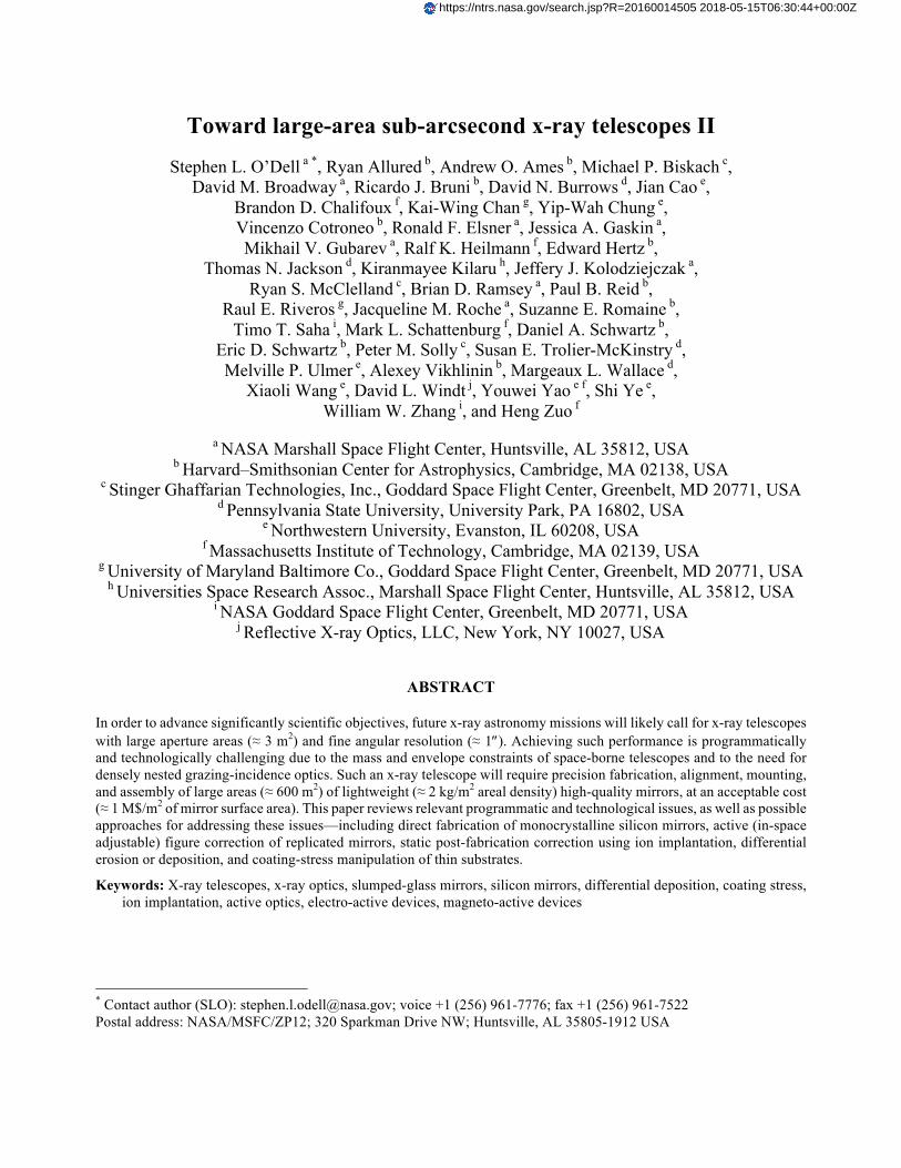
The Chandra X-ray Observatory1,2 (Figure 1, left), NASA’s flagship mission for x-ray astronomy, is a unique astrophysics facility for sub-arcsecond x-ray imaging. The US x-ray-astronomy community is currently investigating mission concepts and enabling technologies in order to propose a worthy successor to Chandra, for launch in the mid 2030s. Although the science-driven requirements for this “X-ray Surveyor” mission3 (Figure 1, right) are still being defined, we anticipate that those requirements will call for an x-ray telescope with an angular resolution comparable to Chandra’s 0.5² half-energy width (HEW) and a collecting area 20–30 times larger than Chandra’s 0.1 m2.
Figure 1. NASA’s Chandra X-ray Observatory (left)—13.8-m length, 4.2-m diameter, 19.5-m wingspan, and 4800-kg mass—features a 10-m focal-length x-ray telescope with angular resolution ≈ 0.5² and collecting area ≈ 0.1 m2. A preliminary “X-Ray Surveyor” concept (right) features an x-ray telescope with angular resolution ≈ 0.5² and collecting area ≈ 3 m2. [Credits: NGST (left); MSFC (right)]
Focusing x-ray telescopes utilize grazing-incidence mirror pairs for true imaging, resulting in mirror surface area many (typically, ≈100) times larger than aperture area. Obtaining large aperture areas requires a densely nested configuration of thin grazing-incidence mirrors to maximize clear aperture within a limited envelope and to minimize mass. As thin, lightweight mirrors are inherently not stiff, all production processes—fabrication, coating, metrology, and mounting—are technically challenging. Applying technical solutions to produce the large mirror areas needed is programmatically challenging. If one assumes that resources (cost, schedule, and mass) for the X-Ray Surveyor mirror assembly will be comparable to those for the Chandra High-Resolution Mirror Assembly (HRMA), scaling the mirror surface area upward by a factor of 30 compared to the HRMA’s 20 m2 implies X-Ray Surveyor goals for areal mass and areal cost of < 2 kg/m2 and < 1 M$/m2, respectively4.
In this paper we update our previous overviews4,5,6,7 of advances toward large-area sub-arcsecond x-ray telescopes. Here we report primarily progress made by the US research groups, represented by the authors of this overview. First we briefly describe general approaches (§2) toward large-area fine-angular-resolution x-ray telescopes. Next we discuss processes aimed at producing precision-figured thin mirrors through initial figuring (§3) during mirror fabrication, through post-fabrication static figure correction (§4), or through post-fabrication active figure correction (§5).
2. APPROACHES
Within assumed constraints (§1) on cost, mass, and envelope, it is not feasible to scale Chandra-like optics—full-cylinder, thick-walled Zerodur™ mirror pairs—to achieve 30 times Chandra’s aperture. Hence, most design concepts for large x-ray telescopes utilize a segmented-optics approach, wherein relatively small mirror segments are aligned and mounted to synthesize densely nested, full-cylinder mirror pairs. The segmented-optics approach has the advantages of scalability to very large mirror assemblies and ease of handling the individual mirrors. On the other hand, monolithic full-cylinder shells are inherently stiffer and easier to align.
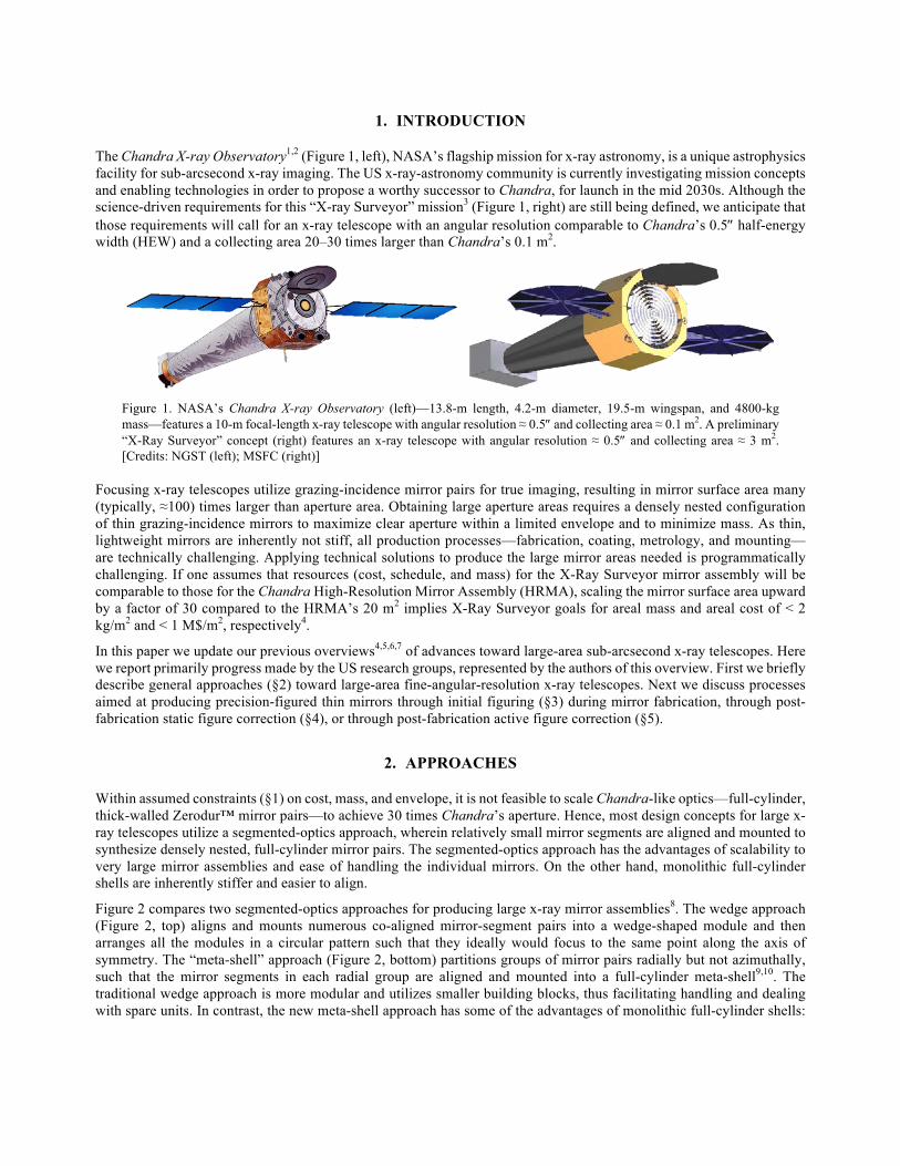
Figure 2 compares two segmented-optics approaches for producing large x-ray mirror assemblies8. The wedge approach (Figure 2, top) aligns and mounts numerous co-aligned mirror-segment pairs into a wedge-shaped module and then arranges all the modules in a circular pattern such that they ideally would focus to the same point along the axis of symmetry. The “meta-shell” approach (Figure 2, bottom) partitions groups of mirror pairs radially but not azimuthally, such that the mirror segments in each radial group are aligned and mounted into a full-cylinder meta-shell9,10. The traditional wedge approach is more modular and utilizes smaller building blocks, thus facilitating handling and dealing with spare units. In contrast, the new meta-shell approach has some of the advantages of monolithic full-cylinder shells:
It recognizes and aligns to the telescope’s optical axis throughout alignment and mounting of the mirror segments and also facilitates design and installation of baffles to suppress stray x rays from outside the telescope’s field of view.
Figure 2. Two approaches for producing an x-ray mirror assembly comprised of segmented grazing-incidence mirror pairs. The wedge approach (top) is traditional; the meta-shell approach (bottom) is being developed at GSFC. [Credits: GSFC/ Will Zhang]
As mounting-induced and gravity-induced distortions of a thin mirror are potentially severe at long spatial wavelengths, an effective mounting and assembly scheme should either preclude or correct low-spatial-frequency deviations. One philosophy is to overconstrain significantly the mirrors by the mount—e.g., using many mounting points per mirror or even longitudinal ribs. While an overconstraining mount can be robust to gravitational distortion and vibration, it limits the ability to correct mirror figure after mounting, as the mount tends to impose its figure on the mirror. The opposite philosophy is to strive for perfectly figured mirrors and to constrain them as little as possible.
If the mounting scheme minimally constrains the mirror, then the mirror must itself be figured to the required precision. Even if the mounting scheme strongly constrains the mirror, the mirror should be figured to the required precision at least at mid and higher spatial frequencies, as mounting is unlikely to correct figure errors at the shorter spatial wavelengths. We distinguish two steps in producing a precision figured mirror—figure generation (§3) during mirror fabrication and (post-fabrication) figure correction, which may be either static (§4) or active (§5).
3. FIGURE GENERATION
Figure generation of mirrors falls into two categories of processes—direct fabrication (§3.1) and replication (§3.2).
3.1. Direct fabrication
Direct fabrication using conventional grinding and polishing combined with precision metrology produced the exquisite Chandra mirrors. However, direct fabrication of precision, thin mirror segments has been problematic for two reasons. First, thin substrates are quite flexible, distorting significantly under the force of traditional grinding and polishing tools. Second, internal stress (inherent in traditional substrate materials) deforms a thin substrate as material is removed.
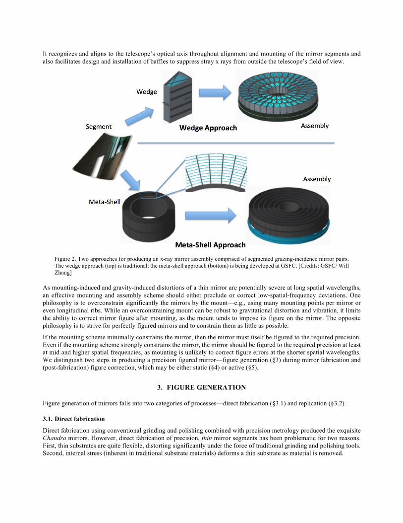
NASA Goddard Space Flight Center (GSFC) is developing a novel approach11,12 (Figure 3) for direct fabrication of thin segmented x-ray mirrors13, which aims to solve both these problems. First, the grinding and polishing are implemented on a thick block of material before the mirror is sliced from the block. Second, the substrate material is mono-crystalline silicon, which has no internal stress in its free state. Finally, etching of the substrate—after slicing from the block using wire electrical discharge machining (EDM)—removes the stress due to surface damage during the processing.
Figure 3. Steps for fabricating a thin segmented mirror substrate from a block of mono-crystalline silicon. Begin with a thick block of mono-crystalline silicon (left); cut, grind, and polish the precision figure of a grazing-incidence mirror into the top of the block (center); slice (wire-EDM) a thin mirror off the block and etch back to remove subsurface damage (right). [Credits: GSFC/ Will Zhang]
In addition to the absence of internal stress, mono-crystalline silicon has thermo-mechanical advantages over glass. In particular, it has higher thermal conductivity, lower coefficient of thermal expansion, and higher elastic modulus. This technology has already resulted in x-ray mirrors with (two-reflection-equivalent) half energy width HEW < 3". GSFC intends to establish the technical possibility of a sub-arcsecond x-ray telescope by building a stack of monocrystalline-silicon mirror pairs with HEW ≈ 1" by the end of 2018. It then plans to demonstrate mass-production processes by building a meta-shell (Figure 2 bottom) with HEW ≈ 1" by 2020.
3.2. Replication
Replication copies the complementary surface figure of a precision figured mandrel onto a thin substrate. As the mandrel can be thick-walled and very stiff, it is fairly insensitive to distortion during figuring and polishing. As replication itself is typically inexpensive compared to precision figuring and polishing, replicated mirrors can be quite cost-effective if the design employs many mirrors of the same size and shape. A crucial disadvantage of replication is that the replica—particularly when very thin—does not reproduce the mandrel’s figure to the required fidelity for sub-arcsecond imaging.
For high-resolution segmented optics, the leading replication method is currently glass slumping14,15,16,17,18,19,20,21. GSFC regularly slumps glass mirrors that would produce a (two-reflection) HEW ≈ 6" if perfectly mounted; it has demonstrated HEW ≈ 8" for a development module containing 3 co-aligned (primary–secondary) mirror pairs22. However, residual stress in the replication process may limit the angular resolution of thin replicated x-ray optics to HEW > 5". Thus, reaching sub-arcsecond resolution using replicated mirrors will likely require post-replication figure correction—either static (§4) or active (§5)—to turn a good x-ray mirror into an excellent one.
4. STATIC FIGURE CORRECTION
After figure generation, fabrication or mount-induced figure errors may require correction to achieve the desired angular resolution. For thin mirrors, the challenge is to correct such figure errors with minimal force and, if possible, in situ. Multiple technologies potentially allow for figure correction of thin mirrors, perhaps in their mounted state. Specifically, US researchers are investigating differential ion implantation (§4.1), ion figuring or differential erosion (§4.2), differential deposition (§4.3), and coating-stress manipulation (§4.4).
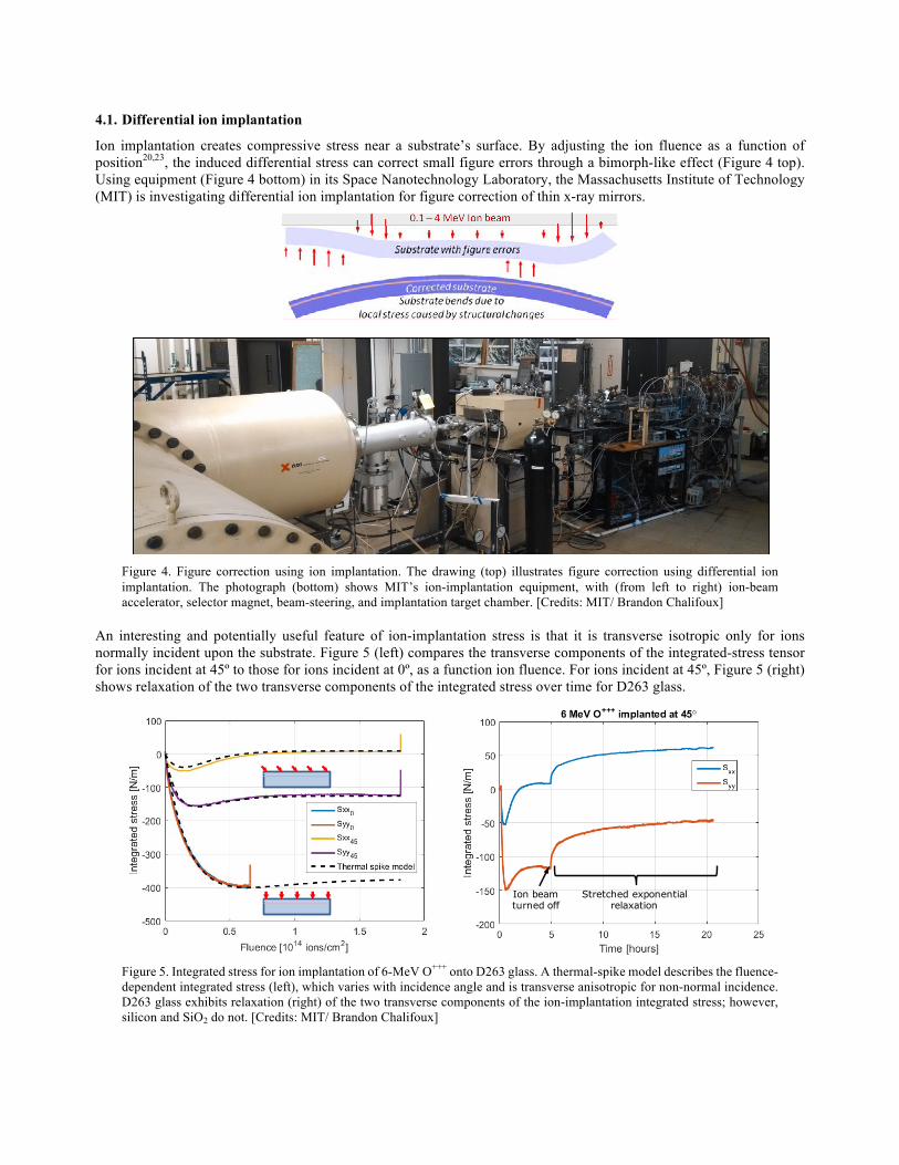
4.1. Differential ion implantation
Ion implantation creates compressive stress near a substrate’s surface. By adjusting the ion fluence as a function of position20,23, the induced differential stress can correct small figure errors through a bimorph-like effect (Figure 4 top). Using equipment (Figure 4 bottom) in its Space Nanotechnology Laboratory, the Massachusetts Institute of Technology (MIT) is investigating differential ion implantation for figure correction of thin x-ray mirrors.
Figure 4. Figure correction using ion implantation. The drawing (top) illustrates figure correction using differential ion implantation. The photograph (bottom) shows MIT’s ion-implantation equipment, with (from left to right) ion-beam accelerator, selector magnet, beam-steering, and implantation target chamber. [Credits: MIT/ Brandon Chalifoux]
An interesting and potentially useful feature of ion-implantation stress is that it is transverse isotropic only for ions normally incident upon the substrate. Figure 5 (left) compares the transverse components of the integrated-stress tensor for ions incident at 45º to those for ions incident at 0º, as a function ion fluence. For ions incident at 45º, Figure 5 (right) shows relaxation of the two transverse components of the integrated stress over time for D263 glass.
Figure 5. Integrated stress for ion implantation of 6-MeV O+++ onto D263 glass. A thermal-spike model describes the fluence-dependent integrated stress (left), which varies with incidence angle and is transverse anisotropic for non-normal incidence. D263 glass exhibits relaxation (right) of the two transverse components of the ion-implantation integrated stress; however, silicon and SiO2 do not. [Credits: MIT/ Brandon Chalifoux]
Ion beam turned off
Stretched exponential relaxation
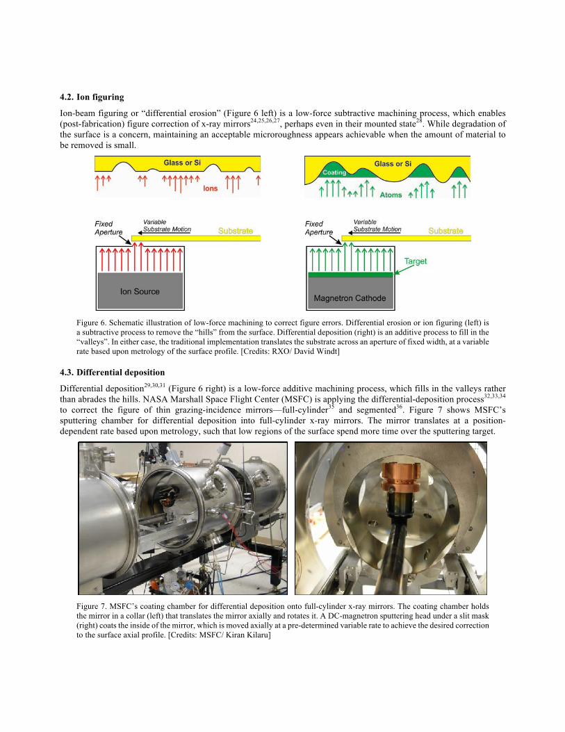
4.2. Ion figuring
Ion-beam figuring or “differential erosion” (Figure 6 left) is a low-force subtractive machining process, which enables (post-fabrication) figure correction of x-ray mirrors24,25,26,27, perhaps even in their mounted state28. While degradation of the surface is a concern, maintaining an acceptable microroughness appears achievable when the amount of material to be removed is small.
Figure 6. Schematic illustration of low-force machining to correct figure errors. Differential erosion or ion figuring (left) is a subtractive process to remove the “hills” from the surface. Differential deposition (right) is an additive process to fill in the “valleys”. In either case, the traditional implementation translates the substrate across an aperture of fixed width, at a variable rate based upon metrology of the surface profile. [Credits: RXO/ David Windt]
4.3. Differential deposition
Differential deposition29,30,31 (Figure 6 right) is a low-force additive machining process, which fills in the valleys rather than abrades the hills. NASA Marshall Space Flight Center (MSFC) is applying the differential-deposition process32,33,34 to correct the figure of thin grazing-incidence mirrors—full-cylinder35 and segmented36. Figure 7 shows MSFC’s sputtering chamber for differential deposition into full-cylinder x-ray mirrors. The mirror translates at a position-dependent rate based upon metrology, such that low regions of the surface spend more time over the sputtering target.
Figure 7. MSFC’s coating chamber for differential deposition onto full-cylinder x-ray mirrors. The coating chamber holds the mirror in a collar (left) that translates the mirror axially and rotates it. A DC-magnetron sputtering head under a slit mask (right) coats the inside of the mirror, which is moved axially at a pre-determined variable rate to achieve the desired correction to the surface axial profile. [Credits: MSFC/ Kiran Kilaru]
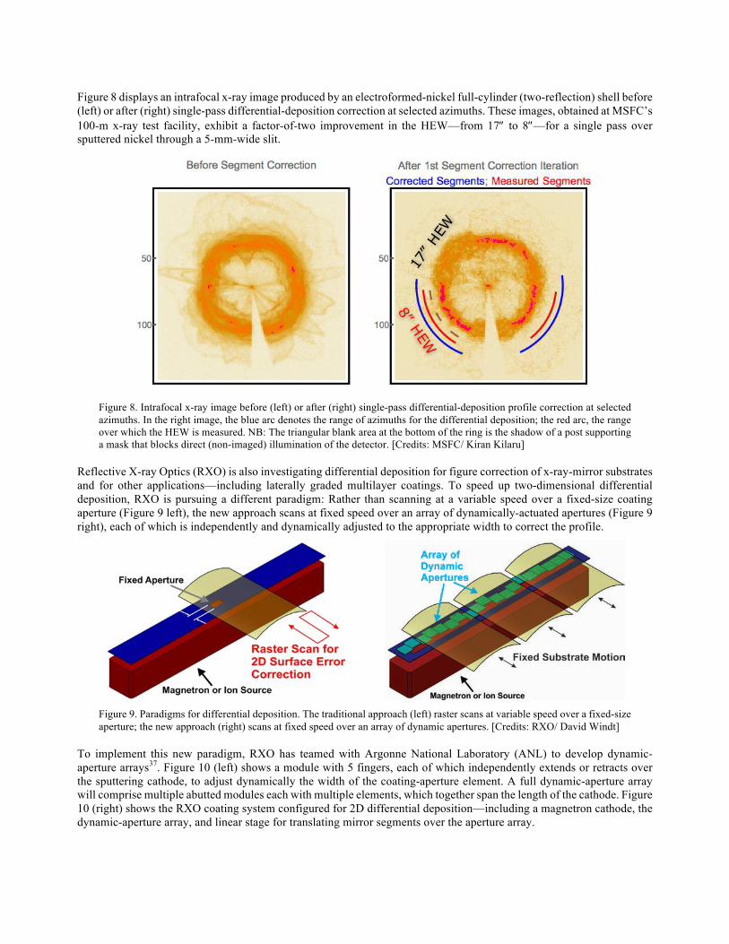
Figure 8 displays an intrafocal x-ray image produced by an electroformed-nickel full-cylinder (two-reflection) shell before (left) or after (right) single-pass differential-deposition correction at selected azimuths. These images, obtained at MSFC’s 100-m x-ray test facility, exhibit a factor-of-two improvement in the HEW—from 17² to 8²—for a single pass over sputtered nickel through a 5-mm-wide slit.
Figure 8. Intrafocal x-ray image before (left) or after (right) single-pass differential-deposition profile correction at selected azimuths. In the right image, the blue arc denotes the range of azimuths for the differential deposition; the red arc, the range over which the HEW is measured. NB: The triangular blank area at the bottom of the ring is the shadow of a post supporting a mask that blocks direct (non-imaged) illumination of the detector. [Credits: MSFC/ Kiran Kilaru]
Reflective X-ray Optics (RXO) is also investigating differential deposition for figure correction of x-ray-mirror substrates and for other applications—including laterally graded multilayer coatings. To speed up two-dimensional differential deposition, RXO is pursuing a different paradigm: Rather than scanning at a variable speed over a fixed-size coating aperture (Figure 9 left), the new approach scans at fixed speed over an array of dynamically-actuated apertures (Figure 9 right), each of which is independently and dynamically adjusted to the appropriate width to correct the profile.
Figure 9. Paradigms for differential deposition. The traditional approach (left) raster scans at variable speed over a fixed-size aperture; the new approach (right) scans at fixed speed over an array of dynamic apertures. [Credits: RXO/ David Windt]
To implement this new paradigm, RXO has teamed with Argonne National Laboratory (ANL) to develop dynamic-aperture arrays37. Figure 10 (left) shows a module with 5 fingers, each of which independently extends or retracts over the sputtering cathode, to adjust dynamically the width of the coating-aperture element. A full dynamic-aperture array will comprise multiple abutted modules each with multiple elements, which together span the length of the cathode. Figure 10 (right) shows the RXO coating system configured for 2D differential deposition—including a magnetron cathode, the dynamic-aperture array, and linear stage for translating mirror segments over the aperture array.
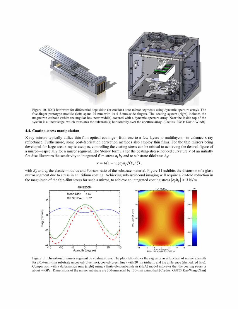
Figure 10. RXO hardware for differential deposition (or erosion) onto mirror segments using dynamic-aperture arrays. The five-finger prototype module (left) spans 25 mm with its 5 5-mm-wide fingers. The coating system (right) includes the magnetron cathode (white rectangular box near middle) covered with a dynamic-aperture array. Near the inside top of the system is a linear stage, which translates the substrate(s) horizontally over the aperture array. [Credits: RXO/ David Windt]
4.4. Coating-stress manipulation
X-ray mirrors typically utilize thin-film optical coatings—from one to a few layers to multilayers—to enhance x-ray reflectance. Furthermore, some post-fabrication correction methods also employ thin films. For the thin mirrors being developed for large-area x-ray telescopes, controlling the coating stress can be critical to achieving the desired figure of a mirror—especially for a mirror segment. The Stoney formula for the coating-stress-induced curvature 𝜅 of an initially flat disc illustrates the sensitivity to integrated film stress 𝜎/ℎ/ and to substrate thickness ℎ1:
𝜅 = 6 1 − 𝜈1 𝜎/ℎ/ 𝐸1ℎ16 ,
with 𝐸1 and 𝜈1 the elastic modulus and Poisson ratio of the substrate material. Figure 11 exhibits the distortion of a glass mirror segment due to stress in an iridium coating. Achieving sub-arcsecond imaging will require a 20-fold reduction in the magnitude of the thin-film stress for such a mirror, to achieve an integrated coating stress 𝜎/ℎ/ < 3N/m.
Figure 11. Distortion of mirror segment by coating stress. The plot (left) shows the sag error as a function of mirror azimuth for a 0.4-mm-thin substrate uncoated (blue line), coated (green line) with 20 nm iridium, and the difference (dashed red line). Comparison with a deformation map (right) using a finite-element-analysis (FEA) model indicates that the coating stress is about -4 GPa. Dimensions of the mirror substrate are 200-mm axial by 130-mm azimuthal. [Credits: GSFC/ Kai-Wing Chan]
The objective of coating-stress manipulation is to produce a coating with very low integrated stress or one with a precisely controlled integrated stress38,39,40,41. In the latter case, the goal is to correct42 long-spatial-wavelength errors that are either intrinsic to the fabricated substrate or introduced by other films42,43 deposited onto the substrate. Correcting shorter spatial-frequency errors requires a precision translating slit44,45, similar to that used for differential deposition (§4.3).
Researchers are pursuing multiple approaches to coating-stress manipulation. These include fine-tuning deposition parameters (§4.4.1), bilayer compensation (§4.4.2), front/back cancellation (§4.4.3), and thermal annealing (§4.4.4).
4.4.1. Deposition parameters
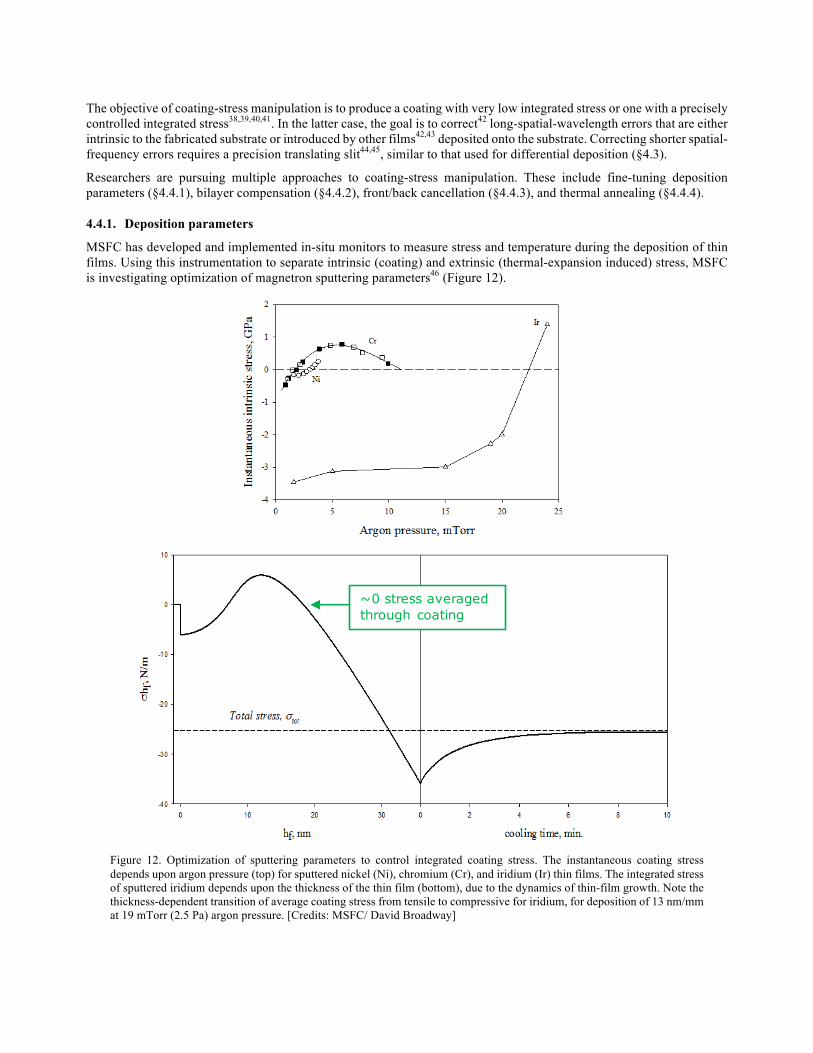
MSFC has developed and implemented in-situ monitors to measure stress and temperature during the deposition of thin films. Using this instrumentation to separate intrinsic (coating) and extrinsic (thermal-expansion induced) stress, MSFC is investigating optimization of magnetron sputtering parameters46 (Figure 12).
Figure 12. Optimization of sputtering parameters to control integrated coating stress. The instantaneous coating stress depends upon argon pressure (top) for sputtered nickel (Ni), chromium (Cr), and iridium (Ir) thin films. The integrated stress of sputtered iridium depends upon the thickness of the thin film (bottom), due to the dynamics of thin-film growth. Note the thickness-dependent transition of average coating stress from tensile to compressive for iridium, for deposition of 13 nm/mm at 19 mTorr (2.5 Pa) argon pressure. [Credits: MSFC/ David Broadway]
~0 stress averaged through coating
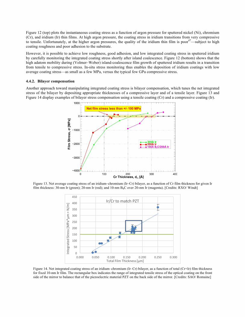
Figure 12 (top) plots the instantaneous coating stress as a function of argon pressure for sputtered nickel (Ni), chromium (Cr), and iridium (Ir) thin films. At high argon pressure, the coating stress in iridium transitions from very compressive to tensile. Unfortunately, at the higher argon pressures, the quality of the iridium thin film is poor47—subject to high coating roughness and poor adhesion to the substrate.
However, it is possible to achieve low roughness, good adhesion, and low integrated coating stress in sputtered iridium by carefully monitoring the integrated coating stress shortly after island coalescence. Figure 12 (bottom) shows that the high adatom mobility during (Volmer–Weber) island-coalescence film growth of sputtered iridium results in a transition from tensile to compressive stress. In-situ stress monitoring thus enables the deposition of iridium coatings with low average coating stress—as small as a few MPa, versus the typical few GPa compressive stress.
4.4.2. Bilayer compensation
Another approach toward manipulating integrated coating stress is bilayer compensation, which tunes the net integrated stress of the bilayer by depositing appropriate thicknesses of a compressive layer and of a tensile layer. Figure 13 and Figure 14 display examples of bilayer stress compensation using a tensile coating (Cr) and a compressive coating (Ir).
Figure 13. Net average coating stress of an iridium–chromium (Ir–Cr) bilayer, as a function of Cr film thickness for given Ir film thickness: 30-nm Ir (green); 20-nm Ir (red); and 10-nm B4C over 20-nm Ir (magenta). [Credits: RXO/ Windt]
Figure 14. Net integrated coating stress of an iridium–chromium (Ir–Cr) bilayer, as a function of total (Cr+Ir) film thickness for fixed 10-nm Ir film. The rectangular box indicates the range of integrated tensile stress of the optical coating on the front side of the mirror to balance that of the piezoelectric material PZT on the back side of the mirror. [Credits: SAO/ Romaine]
0
50
100
150
200
250
300
350
400
450
0.000 0.050 0.100 0.150 0.200 0.250 0.300
Integrated
Stress[M
Pa*μ
m=N/m
]
TotalFilmThickness[μm]
Ir/CrtomatchPZT
The detailed objectives of the two studies summarized in these two figures are somewhat different. In Figure 13, RXO seeks to produce an x-ray optical coating of Ir/Cr with zero net integrated stress. In Figure 14, SAO seeks to produce an x-ray optical coating of Ir/Cr with net integrated tensile stress that cancels the integrated tensile stress of a thin film on the back side of the x-ray mirror. SAO is pursuing this latter application in support of its research to develop adjustable x-ray optics (§5.1), specifically to balance the (static) integrated coating stress (» 200 N/m) of the backside piezoelectric film—lead zirconate titanate (PZT).
4.4.3. Front/back cancellation
A third approach for mitigating the effects of coating stress is front/back cancellation. The idea here is to deposit a coating on each side of the mirror, such that the integrated stress on the back side matches the that on the front side. GSFC has been investigating this approach both for magnetron sputtering and for atomic-layer deposition (ALD). Test results thus far suggest that such a simple correction is not as straightforward to implement as originally believed, for reasons not totally understood.
4.4.4. Thermal annealing
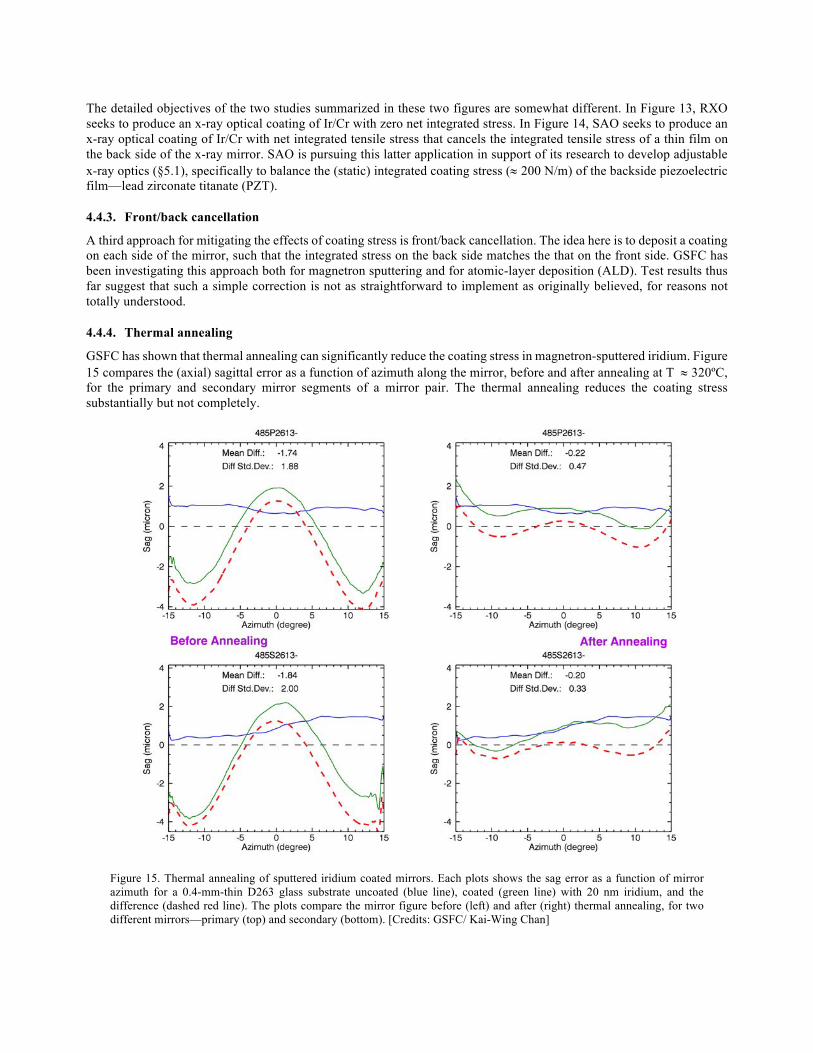
GSFC has shown that thermal annealing can significantly reduce the coating stress in magnetron-sputtered iridium. Figure 15 compares the (axial) sagittal error as a function of azimuth along the mirror, before and after annealing at T » 320ºC, for the primary and secondary mirror segments of a mirror pair. The thermal annealing reduces the coating stress substantially but not completely.
Figure 15. Thermal annealing of sputtered iridium coated mirrors. Each plots shows the sag error as a function of mirror azimuth for a 0.4-mm-thin D263 glass substrate uncoated (blue line), coated (green line) with 20 nm iridium, and the difference (dashed red line). The plots compare the mirror figure before (left) and after (right) thermal annealing, for two different mirrors—primary (top) and secondary (bottom). [Credits: GSFC/ Kai-Wing Chan]
5. ACTIVE FIGURE CORRECTION
In contrast with static figure correction (§4), active figure correction enables adjustment of mirror figure after completion of the mirror assembly, even during in-space operation. Here we very briefly describe thin-film bimorph-like (surface-tangential) actuator technologies currently under development in the US, for active correction of the figure of thin x-ray mirrors. In effect, this approach manipulates the stress in coatings that are electro-active (§5.1, piezoelectric or electrostrictive) or magneto-active (§5.2, magnetostrictive). These Proceedings and previous editions of Adaptive X-ray Optics (SPIE 9208, 8503, and 7803) provide more detailed descriptions and references.
5.1. Thin-film electro-active array
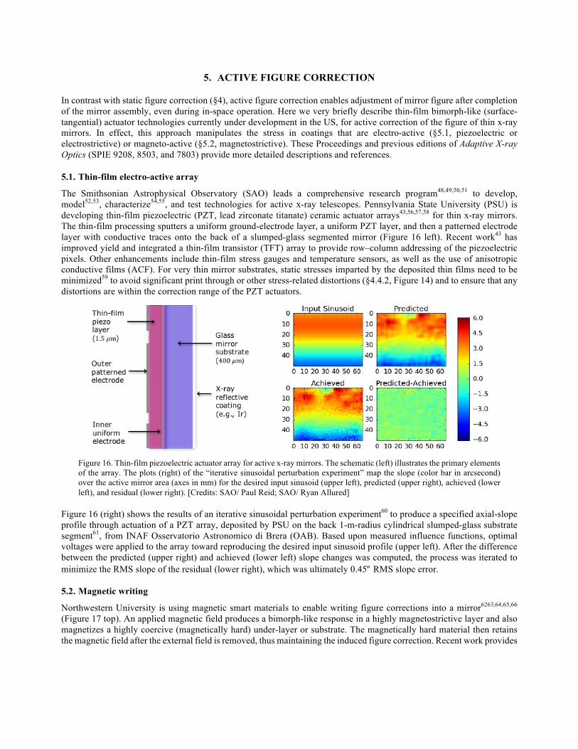
The Smithsonian Astrophysical Observatory (SAO) leads a comprehensive research program48,49,50,51 to develop, model52,53, characterize54,55, and test technologies for active x-ray telescopes. Pennsylvania State University (PSU) is developing thin-film piezoelectric (PZT, lead zirconate titanate) ceramic actuator arrays43,56,57,58 for thin x-ray mirrors. The thin-film processing sputters a uniform ground-electrode layer, a uniform PZT layer, and then a patterned electrode layer with conductive traces onto the back of a slumped-glass segmented mirror (Figure 16 left). Recent work43 has improved yield and integrated a thin-film transistor (TFT) array to provide row–column addressing of the piezoelectric pixels. Other enhancements include thin-film stress gauges and temperature sensors, as well as the use of anisotropic conductive films (ACF). For very thin mirror substrates, static stresses imparted by the deposited thin films need to be minimized59 to avoid significant print through or other stress-related distortions (§4.4.2, Figure 14) and to ensure that any distortions are within the correction range of the PZT actuators.
Figure 16. Thin-film piezoelectric actuator array for active x-ray mirrors. The schematic (left) illustrates the primary elements of the array. The plots (right) of the “iterative sinusoidal perturbation experiment” map the slope (color bar in arcsecond) over the active mirror area (axes in mm) for the desired input sinusoid (upper left), predicted (upper right), achieved (lower left), and residual (lower right). [Credits: SAO/ Paul Reid; SAO/ Ryan Allured]
Figure 16 (right) shows the results of an iterative sinusoidal perturbation experiment60 to produce a specified axial-slope profile through actuation of a PZT array, deposited by PSU on the back 1-m-radius cylindrical slumped-glass substrate segment61, from INAF Osservatorio Astronomico di Brera (OAB). Based upon measured influence functions, optimal voltages were applied to the array toward reproducing the desired input sinusoid profile (upper left). After the difference between the predicted (upper right) and achieved (lower left) slope changes was computed, the process was iterated to minimize the RMS slope of the residual (lower right), which was ultimately 0.45² RMS slope error.
5.2. Magnetic writing
Northwestern University is using magnetic smart materials to enable writing figure corrections into a mirror6263,64,65,66 (Figure 17 top). An applied magnetic field produces a bimorph-like response in a highly magnetostrictive layer and also magnetizes a highly coercive (magnetically hard) under-layer or substrate. The magnetically hard material then retains the magnetic field after the external field is removed, thus maintaining the induced figure correction. Recent work provides
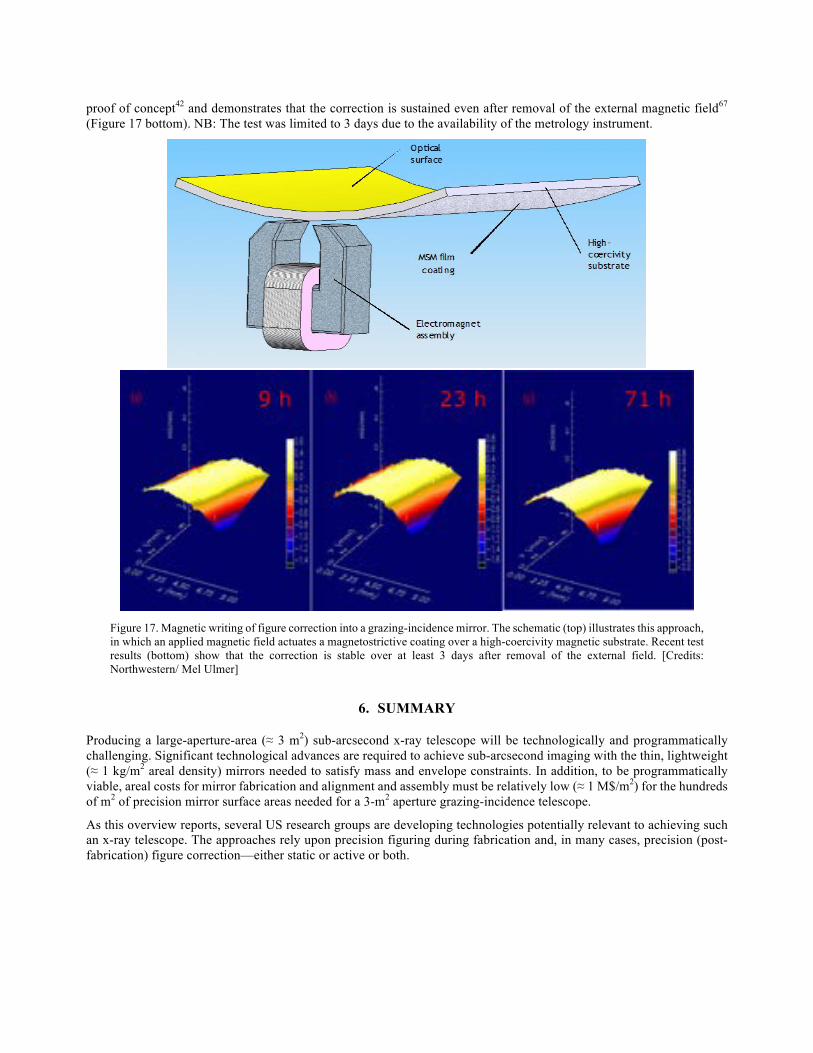
proof of concept42 and demonstrates that the correction is sustained even after removal of the external magnetic field67 (Figure 17 bottom). NB: The test was limited to 3 days due to the availability of the metrology instrument.
Figure 17. Magnetic writing of figure correction into a grazing-incidence mirror. The schematic (top) illustrates this approach, in which an applied magnetic field actuates a magnetostrictive coating over a high-coercivity magnetic substrate. Recent test results (bottom) show that the correction is stable over at least 3 days after removal of the external field. [Credits: Northwestern/ Mel Ulmer]
6. SUMMARY
Producing a large-aperture-area (≈ 3 m2) sub-arcsecond x-ray telescope will be technologically and programmatically challenging. Significant technological advances are required to achieve sub-arcsecond imaging with the thin, lightweight (≈ 1 kg/m2 areal density) mirrors needed to satisfy mass and envelope constraints. In addition, to be programmatically viable, areal costs for mirror fabrication and alignment and assembly must be relatively low (≈ 1 M$/m2) for the hundreds of m2 of precision mirror surface areas needed for a 3-m2 aperture grazing-incidence telescope.
As this overview reports, several US research groups are developing technologies potentially relevant to achieving such an x-ray telescope. The approaches rely upon precision figuring during fabrication and, in many cases, precision (post-fabrication) figure correction—either static or active or both.
REFERENCES
1 O'Dell, S. L., & Weisskopf, M. C., “The role of project science in the Chandra X-ray Observatory,” SPIE 6271, 07 14pp (2006).
2 Weisskopf, M. C., Tananbaum, H. D., Van Speybroeck, L. P., & O'Dell, S. L., “Chandra X-ray Observatory (CXO): overview,” SPIE 4012, 2-16 (2000).
3 Gaskin, J. A., Weisskopf, M. C., Vikhlinin, A., Tananbaum, H. D., Bandler, S. R., Bautz, M. W., Burrows, D. N., Falcone, A. D., Harrison, F. A., Heilmann, R. K., Heinz, S., Hopkins, R. C., Kilbourne, C. A., Kouveliotou, C., Kraft, R. P., Kravtsov, A. V., McEntaffer, R. L., Natarajan, P., O'Dell, S. L., Petre, R., Prieskorn, Z. R., Ptak, A. F., Ramsey, B. D., Reid, P. B., Schnell, A. R., Schwartz, D. A., & Townsley, L. K., “The X-Ray Surveyor mission: a concept study,” SPIE 9601, 0J 14pp (2015).
4 O'Dell, S. L., Aldcroft, T. L., Allured, R., Atkins, C., Burrows, D. N., Cao, J., Chalifoux, B. D., Chan, K.-W., Cotroneo, V., Elsner, R. F., Graham, M. E., Gubarev, M. V., Heilmann, R. K., Johnson-Wilke, R. L., Kilaru, K., Kolodziejczak, J. J., Lillie, C. F., McMuldroch, S., Ramsey, B. D., Reid, P. B., Riveros, R. E., Roche, J. M., Saha, T. T., Schattenburg, M. L., Schwartz, D. A., Trolier-McKinstry, S. E., Ulmer, M. P., Vaynman, S., Vikhlinin, A., Wang, X., Weisskopf, M. C., Wilke, R. H. T., & Zhang, W. W., “Toward large-area sub-arcsecond x-ray telescopes,” SPIE 9208, 05 14pp (2014).
5 O'Dell, S. L., Aldcroft, T. L., Atkins, C., Button, T. W., Cotroneo, V., Davis, W. N., Doel, P., Feldman, C. H., Freeman, M. D., Gubarev, M. V., Johnson-Wilke, R. L., Kolodziejczak, J. J., Lillie, C. F., Michette, A. G., Ramsey, B. D., Reid, P. B., Rodriguez Sanmartin, D., Saha, T. T., Schwartz, D. A., Trolier-McKinstry, S. E., Ulmer, M. P., Wilke, R. H. T., Willingale, R., & Zhang, W. W., “Toward active x-ray telescopes II,” SPIE 8503, 07 15pp (2012).
6 O'Dell, S. L., Atkins, C., Button, T. W., Cotroneo, V., Davis, W. N., Doel, P., Feldman, C. H., Freeman, M. D., Gubarev, M. V., Kolodziejczak, J. J., Michette, A. G., Ramsey, B. D., Reid, P. B., Rodriguez Sanmartin, D., Saha, T. T., Schwartz, D. A., Trolier-McKinstry, S., Wilke, R. H. T., Willingale, R., & Zhang, W. W., “Toward active x-ray telescopes,” SPIE 8147, 1Q 14pp (2011).
7 O'Dell, S. L., Brissenden, R. J., Davis, W. N., Elsner, R. F., Elvis, M. S., Freeman, M. D., Gaetz, T., Gorenstein, P., Gubarev, M. V., Jerius, D., Juda, M., Kolodziejczak, J. J., Murray, S. S., Petre, R., Podgorski, W., Ramsey, B. D., Reid, P. B., Saha, T., Schwartz, D. A., Trolier-McKinstry, S., Weisskopf, M. C., Wilke, R. H. T., Wolk, S., & Zhang, W. W., “High-resolution x-ray telescopes,” SPIE 7803, 0H 19pp (2010).
8 Zhang, W. W., Biskach, M. P., Chan, K.-W., Mazzarella, J. R., McClelland, R. S., Riveros, R. E., Saha, T. T., and Solly, P. M., “Lightweight and high-resolution single-crystal silicon optics for x-ray astronomy,” SPIE 9905, 1S 7pp (2016).
9 Chan, K.-W., Zhang, W. W., Schofield, M. J., Numata, A., Mazzarella, J. R., Saha, T. T., Biskach, M. P., McClelland, R. S., Niemeyer, J., Sharpe, M. V., & Olsen, L. G., “Alignment and distortion-free integration of lightweight mirrors into meta-shells for high-resolution astronomical x-ray optics,” SPIE 9905, 6X 8pp (2016).
10 McClelland, R. S., Bonafede, J. A., Saha, T. T., Solly, P. M., & Zhang, W. W., “Design and analysis of an x-ray mirror assembly using the meta-shell approach,” SPIE 9905, 7A 9pp (2016).
11 Zhang, W. W., Chan, K.-W., Riveros, R. E., & Saha, T. T., “Toward diffraction-limited lightweight x-ray optics for astronomy,” SPIE 9603, 0Q 7pp (2015).
12 Riveros, R. E., Bly, V. T., Kolos, L. D., McKeon, K. P., Mazzarella, J. R., Miller, T. M., & Zhang, W. W. “Fabrication of single-crystal silicon mirror substrates for x-ray astronomical missions,” SPIE 9144, 45 6pp (2014).
13 Riveros, R. E., Biskach, M. P., Allgood, K. D., Mazzarella, J. R., Sharpe, M. V., & Zhang, W. W., “Progress on the fabrication of high resolution and lightweight monocrystalline silicon x-ray mirrors,” SPIE 9905, 21 5pp (2016).
14 Ghigo, M., Proserpio, L., Basso, S., Citterio, O., Civitani, M. M., Pareschi, G., Salmaso, B., Sironi, G., Spiga, D., Tagliaferri, G., Vecchi, G., Zambra, A., Parodi, G., Martelli, F., Gallieni, D., Tintori, M., Bavdaz, M., Wille, E., Ferrario, I., & Burwitz, V., “Slumping technique for the manufacturing of a representative x-ray grazing incidence mirror module for future space missions,” SPIE 8884, 1Q 14pp (2013).
15 Zhang, W. W., Biskach, M. P., Blake, P. N., Bly, V. T., Carter, J. M., Chan, K. W., Gaskin, J. A., Hong, M., Hohl, B. R., Jones, W. D., Kolodziejczak, J. J., Kolos, L. D., Mazzarella, J. R., McClelland, R. S., McKeon, K. P., Miller, T.
M., O'Dell, S. L., Riveros, R. E., Saha, T. T., Schofield, M. J., Sharpe, M. V., & Smith, H. C., “High resolution and high throughput x-ray optics for future astronomical missions,” SPIE 8861, 0N 13pp (2013).
16 Civitani, M., Ghigo, M., Basso, S., Proserpio, L., Spiga, D., Salmaso, B., Pareschi, G., Tagliaferri, G., Burwitz, V., Hartner, G., Menz, B., Bavdaz, M., & Wille, E., “Direct hot slumping and accurate integration process to manufacture prototypal x-ray optical units made of glass,” SPIE 8861, 10 24pp (2013).
17 Zhang, W. W., Biskach, M. P., Blake, P. N., Chan, K. W., Evans, T. C., Hong, M. L., Jones, W. D., Kolos, L. D., Mazzarella, J. M., McClelland, R. S., O'Dell, S. L., Saha, T. T., & Sharpe, M. V., “Lightweight and high angular resolution x-ray optics for astronomical missions,” SPIE 8147, 0K 12pp (2011).
18 Winter, A., Breunig, E., Burwitz, V., Friedrich, P., Hartner, G., Menz, B., & Proserpio, L., “Light-weight glass mirror systems for future x-ray telescopes,” SPIE 8861, 0Q 10pp (2013).
19 Pareschi, G., Basso, S., Bavdaz, M., Citterio, O., Civitani, M. M., Conconi, P., Gallieni, D., Ghigo, M., Martelli, F., Parodi, G., Proserpio, L., Sironi, G., Spiga, D., Tagliaferri, G., Tintori, M., Wille, E., & Zambra, A., “IXO glass mirrors development in Europe,” SPIE 8147, 0L 12pp (2011).
20 Chalifoux, B., Heilmann, R. K., & Schattenburg, M. L., “Shaping of thin glass X-ray telescope mirrors using air bearing slumping and ion implantation,” SPIE 9144, 4D 7pp (2014).
21 Sung, E., Chalifoux, B., Schattenburg, M. L., & Heilmann, R. K., “Non-touch thermal air-bearing shaping of x-ray telescope optics,” SPIE 8861, 0R 8pp (2013).
22 Zhang, W. W., Biskach, M. P., Bly, V. T., Carter, J. M., Chan, K. W., Gaskin, J. A., Hong, M., Hohl, B. R., Jones, W. D., Kolodziejczak, J. J., Kolos, L. D., Mazzarella, J. R., McClelland, R. S., McKeon, K. P., Miller, T. M., O'Dell, S. L., Riveros, R. E., Saha, T. T., Schofield, M. J., Sharpe, M. V., & Smith, H. C., “Affordable and lightweight high-resolution x-ray optics for astronomical missions,” SPIE 9144, 15 9pp (2014).
23 Chalifoux, B., Sung, E., Heilmann, R. K., & Schattenburg, M. L., “High-precision figure correction of x-ray telescope optics using ion implantation,” SPIE 8861, 0T 13pp (2013).
24 Civitani, M., Ghigo, M., Hołyszko, J., Vecchi, G., & Basso, S., “Ion beam figuring of thin glass plates: achievements and perspectives,” SPIE 9905, 78 8pp (2016).
25 Umetsu, H., Sakai, Y., Tsuru, T., & Yamamoto, M., “Evaluation of ion milled soft x-ray multilayer mirrors for reflection wavefront correction,” JVSJ 53, 368-370 (2010).
26 Gawlitza, P., Braun, S., Dietrich, G., Menzel, M., Schädlich, S., & Leson, A., “Ion beam sputtering of x-ray multilayer mirrors,” SPIE 7077, 03 11pp (2008).
27 Geril, N., Grigely, L. J., Wilson, S. R., & Goela, J. S., “Thin-shell replication of grazing incidence (Wolter type I) SiC mirrors,” SPIE 2478, 215-227 (1995).
28 Gailly, P., de Chambure, D., Collette, J. P., Jamar, C. A. J., Laine, R., Mazy, E., Medart, P., & Stockman, Y., “New process for x-ray mirror image quality improvement,” SPIE 4782, 46-57 (2002).
29 Ablett, J. M., Kao, C. C., & Lunt, A., “The design and performance of an x-ray micro-focusing system using differentially deposited elliptical mirrors at the National Synchrotron Light Source,” RScI 73, 3464-3468 (2002).
30 Ice, G. E., Chung, J.-S., Tischler, J. Z., Lunt, A., & Assoufid, L., “Elliptical x-ray microprobe mirrors by differential deposition,” RScI 71, 2635-2639 (2000).
31 Cai, Z., Yun, W., & Plag, P., “Parameter optimization for producing an elliptical surface from a spherical surface by differential deposition,” SPIE 2516, 52-68 (1995).
32 Kilaru, K., Ramsey, B. D., Gubarev, M. V., & Gregory, D. A., “Differential deposition technique for figure corrections in grazing-incidence x-ray optics,” OptEn 50, 106501 6pp (2011).
33 Kilaru, K., Ramsey, B. D., Gubarev, M. V., Gaskin, J. A., O'Dell, S. L., & Zhang, W., “Differential deposition to correct surface figure deviations in astronomical grazing-incidence x-ray optics,” SPIE 8147, 0X 8pp (2011).
34 O'Dell, S. L., Atkins, C., Broadway, D. M., Elsner, R. F., Gaskin, J. A., Gubarev, M. V., Kilaru, K., Kolodziejczak, J. J., Ramsey, B. D., Roche, J. M., Swartz, D. A., Tennant, A. F., Weisskopf, M. C., & Zavlin, V. E., “X-ray optics at NASA Marshall Space Flight Center,” SPIE 9510, 03 14pp (2015).
35 Kilaru, K., Atkins, C., Ramsey, B. D., Kolodziejczak, J. K., Lis, T. M., Gubarev, M. V., O'Dell, S. L., Gaskin, J. A.,
& Broadway, D. M., “Progress in differential deposition for improving the figures of full-shell astronomical grazing incidence x-ray optics,” SPIE 9603, 1F 9pp (2015).
36 Atkins, C., Kilaru, K., Ramsey, B. D., Broadway, D. M., Gubarev, M. V., O'Dell, S. L., & Zhang, W. W., “Differential deposition correction of segmented glass x-ray optics,” SPIE 9603, 1G 14pp (2015).
37 Windt, D. L., & Conley, R., “Two-dimensional differential deposition: figure correction of thin-shell mirror substrates for x-ray astronomy,” SPIE 9603, 1H 12pp (2015).
38 Chan, K.-W., Sharpe, M., Zhang, W., Kolos, L., Hong, M., McClelland, R., Hohl, B., Saha, T., & Mazzarella, J., “Coating thin mirror segments for lightweight x-ray optics,” SPIE 8861, 0X 12pp (2013).
39 Chan, K.-W., Zhang, W. W., Windt, D., Hong, M.-L., Saha, T., McClelland, R., Sharpe, M., & Dwivedi, V. H., “Reflective coating for lightweight x-ray optics,” SPIE 8443, 3S 11pp (2012).
40 Windt, D. L., “Reduction of stress and roughness by reactive sputtering in W/B4C multilayer films,” SPIE 6688, 0R 10pp (2007).
41 Heilmann, R. K., Monnelly, G. P., Mongrard, O., Butler, N., Chen, C. G., Cohen, L. M., Cook, C. C., Goldman, L. M., Konkola, P. T., McGuirk, M., Ricker, G. R., & Schattenburg, M. L., “Novel methods for shaping thin-foil optics for x-ray astronomy,” SPIE 4496, 62-72 (2002).
42 Ulmer, M. P., Wang, X., Knapp, P., Cao, J., Cao, Y., Karian, T., Grogans, S., Graham, M. E., Vaynman, S., & Yao, Y., “Comparisons of the deflections of magnetically smart films on alloy of NiCo and glass substrates,” SPIE 9208, 08 11pp (2014).
43 Johnson-Wilke, R. L., Wilke, R. H. T., Wallace, M., Ramirez, J. I., Prieskorn, Z., Nikoleyczik, J., Cotroneo, V., Allured, R., Schwartz, D. A., McMuldroch, S., Reid, P. B., Burrows, D. N., Jackson, T. N., & Trolier-McKinstry, S., “ZnO thin film transistors and electronic connections for adjustable x-ray mirrors: SMART-X telescope,” SPIE 9208, 09 9pp (2014).
44 Yao, Y., Wang, X., Cao, J., & Ulmer, M., “Stress manipulated coating for fabricating lightweight x-ray telescope mirrors,” OExpr 23, 28605 14pp (2015).
45 Yao, Y., Wang, X., Cao, J., Graham, M. E., Vaynman, S., Grogans, S. E., Cao, Y., & Ulmer, M. P., “Stress manipulated coating for figure reshape of light weight x-ray telescope mirrors,” SPIE 9603, 1J 7pp (2015).
46 Broadway, D. M., Weimer, J., Gurgew, D., Lis, T., Ramsey, B. D., O'Dell, S. L., Gubarev, M., Ames, A., & Bruni, R., “Achieving zero stress in iridium, chromium, and nickel thin films,” SPIE 9510, 0E 15pp (2015).
47 Döhring, T., Probst, A.-C., Stollenwerk, M., Wen, M., & Proserpio, L., “Development of low-stress iridium coating for astronomical x-ray mirrors,” SPIE 9905, 6V 7pp (2016).
48 Reid, P. B., Aldcroft, T. L., Cotroneo, V., Davis, W., Johnson-Wilke, R. L., McMuldroch, S., Ramsey, B. D., Schwartz, D. A., Trolier-McKinstry, S., Vikhlinin, A., & Wilke, R. H. T., “Development status of adjustable grazing incidence optics for 0.5 arc second x-ray imaging,” SPIE 8861, 1Q 8pp (2013).
49 Reid, P. B., Aldcroft, T. L., Cotroneo, V., Davis, W., Johnson-Wilke, R. L., McMuldroch, S., Ramsey, B. D., Schwartz, D. A., Trolier-McKinstry, S., Vikhlinin, A., & Wilke, R. H. T., “Technology development of adjustable grazing incidence x-ray optics for sub-arc second imaging,” SPIE 8443, 0T 8pp (2012).
50 Cotroneo, V., Davis, W. N., Marquez, V., Reid, P. B., Schwartz, D. A., Johnson-Wilke, R. L., Trolier-McKinstry, S. E., & Wilke, R. H. T., “Adjustable grazing incidence x-ray optics based on thin PZT films,” SPIE 8503, 09 10pp (2012).
51 Reid, P. B., Davis, W., Schwartz, D. A., Trolier-McKinstry, S., & Wilke, R. H. T., “Technology challenges of active x-ray optics for astronomy,” SPIE 7803, 0I 9pp (2010).
52 Aldcroft, T. L., Schwartz, D. A., Reid, P. B., Cotroneo, V., & Davis, W. N., “Simulating correction of adjustable optics for an x-ray telescope,” SPIE 8503, 0F 9pp (2012).
53 Schwartz, D. A., Cotroneo, V., Davis, W., Freeman, M., & Reid, P., “Adjustable x-ray optics: correction for gravity-induced figure errors,” SPIE 8147, 1S 9pp (2011).
54 Allured, R., Ben-Ami, S., Cotroneo, V., Marquez, V., McMuldroch, S., Reid, P. B., Schwartz, D. A., Trolier-
McKinstry, S., Vikhlinin, A. A., & Wallace, M. L., “Improved control and characterization of adjustable x-ray optics,” SPIE 9603, 1M 10pp (2015).
55 Cotroneo, V., Davis, W. N., Reid, P. B., Schwartz, D. A., Trolier-McKinstry, S., & Wilke, R. H. T., “Adjustable grazing incidence x-ray optics: measurement of actuator influence functions and comparison with modeling,” SPIE 8147, 1R 12pp (2011).
56 Wilke, R. H. T., Johnson-Wilke, R. L., Cotroneo, V., Davis, W. N., Reid, P. B., Schwartz, D. A., & Trolier-McKinstry, S., “Sputter deposition of PZT piezoelectric films on thin glass substrates for adjustable x-ray optics,” ApOpt 52, 3412-3419 (2013).
57 Johnson-Wilke, R. L., Wilke, R. H. T., Cotroneo, V., Davis, W. N., Reid, P. B., Schwartz, D. A., & Trolier-McKinstry, S., “Improving yield of PZT piezoelectric devices on glass substrates,” SPIE 8503, 0A 9pp (2012).
58 Wilke, R. H. T., Trolier-McKinstry, S., Reid, P. B., & Schwartz, D. A., “PZT piezoelectric films on glass for Gen-X imaging,” SPIE 7803, 0O:1-10 (2010).
59 Ames, A., Bruni, R., Cotroneo, V., Johnson-Wilke, R., Kester, T., Reid, P., Romaine, S., Tolier-McKinstry, S., & Wilke, R. H. T., “Using iridium films to compensate for piezo-electric materials processing stresses in adjustable x-ray optics,” SPIE 9603, 1I 8pp (2015).
60 Allured, R., Hertz, E., Marquez, V., Cotroneo, V., Wallace, M., Salmaso, B., Civitani, M., Trolier-McKinstry, S., Vikhlinin, A. A., Pareschi, G., & Reid, P. B., “Laboratory demonstration of the piezoelectric figure control of a cylindrical slumped glass optic,” SPIE 9905, 54 8pp (2016).
61 Salmaso, B., Basso, S., Civitani, M., Ghigo, M., Holyszko, J., Pelliciari, C., Spiga, D., Vecchi, G., & Pareschi, G., “Slumped glass foils as substrate for adjustable x-ray optics,” SPIE 9965, Paper 11 15pp (2016).
62 Wang, X., Yao, Y., Cao, J., Vaynman, S., Graham, M. E., Liu, T., & Ulmer, M. P., “Investigation of magnetically smart films applied to correct the surface profile of light weight X-ray optics in two directions,” SPIE 9603, 1O 9pp (2015).
63 Ulmer, M. P., Graham, M. E., Vaynman, S., Cao, J., & Takacs, P. Z., “Deformable mirrors for x-ray astronomy and beyond,” SPIE 8076, 05 10pp (2011).
64 Ulmer, M. P., Graham, M. E., Vaynman, S., Cao, J., & Takacs, P. Z., “Magnetic smart material application to adaptive x-ray optics,” SPIE 7803, 09 11pp (2010).
65 Ulmer, M. P., Wang, X., Cao, J., Savoie, J., Bellavia, B., Graham, M. E., & Vaynman, S., “Progress report on using magneto-strictive sputtered thin films to modify the shape of a x-ray telescope mirror,” SPIE 8503, 0C 8pp (2012).
66 Wang, X., Cao, J., Ulmer, M. P., Graham, M. E., Vaynman, S., Savoie, J., & Bellavia, B., “Comparing theory with experimental data in studying the deformation of magnetically smart films deposited on nickel and glass substrates,” SPIE 8503, 0D 8pp (2012).
67 Wang, X., Yao, Y., Ye, S., Liu, T., Assoufid, L., Cao, J., & Ulmer, M. P., “Shaping Si, NiCo, and glass substrates via stresses in the coatings,” SPIE 9965, Paper 13 9pp (2016).