towards a design process for modeling mas …...towards a design process for modeling mas...
TRANSCRIPT

Towards a Design Process for Modeling MASOrganizations
Massimo Cossentino1, Carmelo Lodato1, Salvatore Lopes1, Patrizia Ribino1,Valeria Seidita2 and Antonio Chella2
1 Istituto di Reti e Calcolo ad Alte Prestazioni,Consiglio Nazionale delle Ricerche, Palermo, Italy
{cossentino,c.lodato,lopes,ribino}@pa.icar.cnr.it2 Dipartimento di Ingegneria Chimica Gestionale Informatica Meccanica
Universita degli Studi di Palermo, Italy{seidita,chella}@dinfo.unipa.it
Abstract. The design of MAS organizations is a complex activity wherea proper methodological approach may offer a significant advantage inenabling the conception of the best solution. Moreover, the aid providedby a supporting tool significantly contributes to make the approach tech-nically sound and it is a fundamental ingredient of a feasible strategy tothe development of large MASs. In this paper, we introduce a portionof methodological approach devoted to design MAS organizations and apreliminary version of a specific case tool, named MoT (Moise+ Tool),for supporting activities from design production to automatic code gener-ation. MoT provides four kinds of diagrams based on a definite graphicalnotation for representing organizational elements. Our process is appliedto a classical write paper simulator example. Results include portion ofthe automatically generated code according to Moise+ specifications.
1 Introduction
Distributed and open systems are widely employed in the simulation and man-agement of highly complex scenarios in dynamic environments. To this end, suchsystems should act in quasi-real time to changes occurring in the environmentadopting the most suitable behavior for reacting to the new conditions. Agentscan provide a good way for solving complex problems and they are very usefulto both design and implementation levels [13][14].
The ability of simulating complex hierarchical organization provides furtherutility to the design of multi-agent systems (MAS from now on). In other words,organizations can be seen as a set of constraints [4] that rules the behavior ofevery single agent in a multi agent society.
The implementation of an organization in a MAS is normally decided atdesign time. The way in which a MAS may re-organize itself has then to beinvestigated from two different points of view, i.e. the design (methodological)and the implementation point of view. A robust approach to agent organizationscomes from the work of Hubner et al. [10] where a definition of an organizational
model (Moise+) is presented. MASs designed in accord with the Moise+ modelare able to re-organize their processes and then react to what occurs in theenvironment.
Organizations are described in the Moise+ model by three main views: thestructural, the functional and normative perspectives. In this model an organi-zation is established a priori (created at design-time) and the agents ought tofollow it. The structural and functional view are considered almost independentwhile the normative dimension is used for establishing a link between them. Fur-thermore, the Moise+ model is complemented with a development tool calledJ-Moise+[7], a Jason extension allowing developers to use Jason for program-ming agents and their organizations [1]. This is nevertheless a powerful tool, butit is not still adequately supported by a well defined methodological approach.
Some researchers have developed in the past other methodologies for MASswhere some aspects of organization were modeled. In [16] the concepts of envi-ronment, roles, interactions and organizational rules are considered as organiza-tional abstractions. Another example has been proposed in [3] where holarchyrepresents the organization structure of the MAS made of holons [5], hence themain element to be developed for building the MAS organization. Despite thenumber of methodologies only few of them cover the entire process lifecycle, fromanalysis to implementation, and above all very few is aided by tools.
In this paper we introduce a portion of methodological approach devotedto design MAS organizations and a preliminary version of a specific case tool,named MoT (Moise+ Tool), for supporting our approach from design productionto automatic code generation.
In particular, MoT is based on a UML compliant graphical notation to rep-resent the Moise+ specific elements and on a code generator in order to producethe final XML code containing the Moise+ organizational specification.
MoT has been realized by using a known tool, Metaedit+ by Metacase [12][6],that offers a valid environment for domain specific modeling. Metaedit+ providesmeans for creating an ad-hoc modeling language with concepts and rules from awell specific problem domain, and notation to be used for drawing diagrams.
The advantages of graphically representing organizations are evident: first ofall, graphical notations are more readable and understandable at a glance thanany coding language, secondly it is usually easier to explain a graphical notationto stakeholders involved in the design (that are not technical designers) than readthe application code with them. The possibility of involving stakeholders likesystem users enables the adoption of agile or extreme development approachesand improves the flexibility of conventional ones.
The remainder of the paper is organized as follows. In section 2 the Moise+organizational model and Metaedit+ are introduced. In section 3 we present ourtool with the definite notation. Section 4 shows a portion of the design processfor developing organizational MAS with the related work products. Such pro-cess is explained applying it to an example inspired by the Moise+ tutorial [8].Moreover, in this section we address the issues concerning the Moise+ code gen-

eration. Finally some discussions and conclusions are drawn in section 5 togetherwith a comparison with others MAS modeling proposals.
2 Background and Motivation
Since the beginning of computer science the need for adequately managing con-cepts related to the applications under development raised with the complexityof systems. A promising approach to this issue has been the definition of meansfor specifying what a system should do instead of how to do something. This ap-proach led to formulation of the Model driven Engineering [11] (MDE) paradigmthat deeply changed the way of thinking and then working of designers and pro-grammers.
Designers and developers are no more involved in the specification of eachsingle detail of the system using a programming language but they can modelthe needed functionalities and the architecture of the system. This fact presentsmany advantages like the increasing goodness of the softwares produced, theeasiness and the rapidity of conveying information among team members and thepossibility, through the use of model transformation techniques, of automaticallygenerating code. However this latter issue is not still supported by adequatelytechnology.
Our work focuses on the creation of a notation and a CASE tool, created as aninstance of a meta-CASE tool (Metaedit+), for supporting the methodologicalactivities involved in the development of organizational MASs. In so doing weexploited the Moise+ organizational model and the features of Metaedit+ forcreating a graphical environment allowing the designer to implement conceptsand rules of the Moise+ model in specific design diagrams and to automaticallyproduce portions of code.
In the next subsections an overview of Moise+ and Metaedit+ is given.
2.1 Moise+
Moise+ [9][10] is an organizational model for MASs based on a few key elementsto characterize an organization. It provides MASs with an explicit definition oftheir organizations. The organizational specification is useful both to the agentsto clearly know their organizational structure and their particular purpose and tothe organization framework, to ensure that the agents follow the specifications.More specifically, Moise+ looks at organization as a three dimensional elementcharacterized by structural, functional and normative dimension.
Looking only at the structural dimension, an organization can be seen as a setof Roles linked by Relations and clustered into Groups. The functional dimensionenriches the model showing the global objectives of the organization. It givessome information about the plans and the way for reaching the organizationalglobal goals by means of Social Schemes. In these schemes the functionalities ofthe organization are represented as Goals grouped into Missions.

Finally, the normative dimension is fundamental into the Moise+ model be-cause it shows the connecting elements, the Norms, between the functional andstructural dimension of an organization. It defines the behavioral rules to beobserved by Roles in order to reach the organizational global goal. Defining thenorms basing on Moise+ means to create links between Roles and Missions. Ac-tually, Moise+ supports two kinds of norms: the Permission and the Obligationnorms.
Practically, designing an organization using the Moise+ model means to de-fine an Organizational Specification (OS) which is the union of the structural,functional and normative specification corresponding to each dimension. An OSis an XML file with a precise structure that defines the features of the previouslymentioned elements. In the following a portion of Moise+ XML code represent-ing the skeleton of a classical Organizational Specification is reported. This codeshows not only the main elements to be defined inside each specification but alsothe order in which the elements have to be defined.
< organisational − specification >< structural − specification >
< role − definitions > . . .< group − specification > . . .< formation − constraints > . . .
< /structural − specification >
< functional − specification >< scheme >
< goal > . . .< mission > . . .
< /scheme >< /functional − specification >
< normative − specification >< normtype =?role =?mission =? > . . .
< /normative − specification >< /organisational − specification >
Fig. 1. Moise+ XML code representing an organizational specification
In section 3 we present the proposed CASE tool developed in order to easilyrealize organization with Moise+.
2.2 Metaedit+
Recently designers manifested the need for changing CASE tools in order tocustomize them for their demands and to meet the features of different applica-tion domains. This customization is not possible with every CASE tool becausetools constrain how the designer can do their work, how they can draw dia-grams/models or manage tool concepts. Generally tools allow to use only fixedmethods and notation.
What Metaedit+ proposes is a way for overcoming this limitation by addingthe notion of meta-CASE tool to that of CASE tool. The meta-CASE tool is

based on a three layered architecture in which the lowest level is the model level,hence the system design. The middle level contains a model of the bottom level,the model of a model is called metamodel. Metamodel contains concepts andrules for creating models. These two levels are already present in a CASE toolbut the metamodel is imposed by the creators of the tool thus implying theprevious said rigidity.
With the introduction of the third layer (the meta-metamodel one) Metaedit+establishes concepts and rules for creating metamodels, indeed Metaedit+ offersthe possibility of modifying the metamodel by following the rules established inthe meta-metamodel, thus overcoming the constraints of CASE tools and havingthe possibility of specifying modeling languages that can then be used with theright tool. Metaedit+ is at the same time a CASE tool and a meta-CASE tool;by using the meta-CASE tool the designer may specify her/his own modelinglanguage that (s)he can use by instantiating the meta-CASE tool in the CASEtool.
MetaEdit+ is based on a specific metamodeling language, GOPPRR thatmeans Graph, Object, Property, Port, Relationship and Role. They are themetatypes used for defining modeling languages and each of them has its ownsemantic. Graph is the individual model, usually a diagram, the object is themain element of the graph, the relationships connect objects, the role connectsrelationships and objects, port gives the possibility to add semantics to the roleand the property. The structure and the semantic of each modeling language canbe described by a metamodel created by using these metatypes.
In addition to the previous features Metaedit+ offers an optimum support tothe UML modeling language on which a lot of design methodologies are based.Finally Metaedit+ offers some preinstalled reports, or the possibility of cre-ating new ones by using a specific language, the Metaedit Reporting Language(MERL). The report is a small program defined and working onto every diagramand, in addition to other facilities it offers, there is the document generation inhtml format or others and the generation of code skeleton in various program-ming languages (Java, C, C++, . . . ). The more the description of each singleelement of the diagram is precise and detailed the more the produced code iscomplete.
This latter functionality has been highly exploited in order to create a reportfor each single newly introduced diagram of the proposed work and to generatethe corresponding xml code.
3 An organization design tool: MoT
The Moise+ Tool (MoT3) wants to be a tool supporting all the phases from theagent organization design to Moise+ code generation. MoT has been realized byusing Metaedit+. It owns a graphical notation to represent the Moise+ specificelements and a code generator in order to produce the final XML code containingthe Moise+ organizational specification. Fig. 2 shows a screenshot of MoT.
3 MoT is available at http://www.pa.icar.cnr.it/aose/MoT.html

Fig. 2. A Screenshot of MoT
MoT is based on the metamodel shown in Fig. 3, it describes an organi-zational structure for MASs adapted from Moise+. The core element of themetamodel is the Organization that pursues some objectives (Goals), each ofthem reachable executing a particular Plan. A Group is usually responsible of atleast a Scheme and a Scheme can be adopted to monitor the execution of anotherScheme. A Scheme contains several Missions composed of a set of Goals. In addi-tion, an Organization is composed of several Roles. When an agent adopts a Roleit is committed to a Mission that is regulated by means of Norms. The Orga-nizational Link and the Compatibility Link respectively define social exchangesand compatibility relations among agent roles.
is committed to
pursuesOrganization
Norms
Role
MissionSchemeGroup
PlanGoal
Compatibility LinkOrganizational
Link
Responsibility
Monitor
Fig. 3. Metamodel adopted in the MoT
In the following subsections we present the adopted notation.
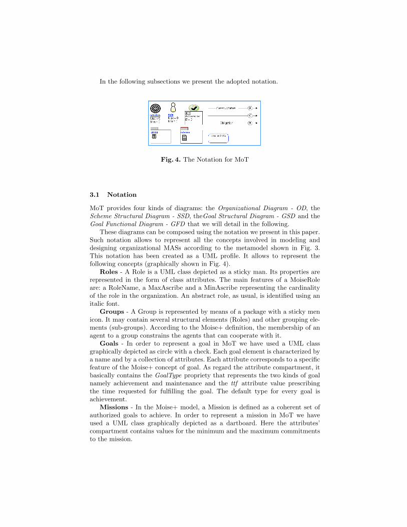
Fig. 4. The Notation for MoT
3.1 Notation
MoT provides four kinds of diagrams: the Organizational Diagram - OD, theScheme Structural Diagram - SSD, theGoal Structural Diagram - GSD and theGoal Functional Diagram - GFD that we will detail in the following.
These diagrams can be composed using the notation we present in this paper.Such notation allows to represent all the concepts involved in modeling anddesigning organizational MASs according to the metamodel shown in Fig. 3.This notation has been created as a UML profile. It allows to represent thefollowing concepts (graphically shown in Fig. 4).
Roles - A Role is a UML class depicted as a sticky man. Its properties arerepresented in the form of class attributes. The main features of a MoiseRoleare: a RoleName, a MaxAscribe and a MinAscribe representing the cardinalityof the role in the organization. An abstract role, as usual, is identified using anitalic font.
Groups - A Group is represented by means of a package with a sticky menicon. It may contain several structural elements (Roles) and other grouping ele-ments (sub-groups). According to the Moise+ definition, the membership of anagent to a group constrains the agents that can cooperate with it.
Goals - In order to represent a goal in MoT we have used a UML classgraphically depicted as circle with a check. Each goal element is characterized bya name and by a collection of attributes. Each attribute corresponds to a specificfeature of the Moise+ concept of goal. As regard the attribute compartment, itbasically contains the GoalType propriety that represents the two kinds of goalnamely achievement and maintenance and the ttf attribute value prescribingthe time requested for fulfilling the goal. The default type for every goal isachievement.
Missions - In the Moise+ model, a Mission is defined as a coherent set ofauthorized goals to achieve. In order to represent a mission in MoT we haveused a UML class graphically depicted as a dartboard. Here the attributes’compartment contains values for the minimum and the maximum commitmentsto the mission.
Social Schemes - A Social Scheme or simply Scheme in Moise+ is composedof a functional goal decomposition tree (where the root is the objective of theScheme and the goals are decomposed within global plan) and a set of missions(where the responsibilities for the sub-goals are grouped to be distributed amongRoles). In our tool, we prefer split its structural aspect (described in the SSDand represented by means of a UML package) from the functional one (describedas a plan in the GFD). Thus, the schemes in the SSD are represented only as aset of associated missions while the GFD shows further features.
Relationships - The elements of the model can be logically related oneanother using several kinds of relationships. We omit to define the commonUML relations that we use in MoT diagrams. In the following we describe thosespecially introduced for specifying Moise+ concepts.
. Organizational Link - It defines the way in which social exchanges be-tween agent roles occur. Moise+ model defines three types of Organizationallinks: communication representing exchange of information; authority defin-ing control power; acquaintance representing knowledge about other agents.In MoT these relations are graphically represented by the first relation shownin Fig. 4 and can be characterized by means of a label showing the type.
. Compatibility Link - It is always plotted between two roles and estab-lishes the possibility for an agent to simultaneously play the two roles. It isgraphically represented by the second relation shown in Fig. 4. When thelink is oriented, it means that the agent playing the source role can play thetarget role but not the vice-versa.
. Norm - In the Moise+ model, a role is usually linked by means of Normsto one or more missions defined in a particular scheme. In our tool, we havedefined a new link type named MoiseNormLink graphically represented bythe third relation shown in Fig. 4. This link is characterized by the Norm-LinkType propriety and can take two values: Obligation and Permission. InMoT this link is a directed arc that starts always from a Role to a Mission.It expresses that an agent playing the role is obliged/allowed to fulfill themission.
In the following section we introduce all phases of our methodological ap-proach with the related work products (MoT diagrams). Our design process willbe detailed with the aid of the the classical example (“Writing paper”) reportedin the Moise Tutorial [8].
4 Methodological Approach
We aim at defining a complete methodological approach ranging from require-ments analysis to code production and system deployment. Such a methodologywill include a goal oriented analysis (with some features inspired by the i* [15]and Tropos [2] approaches), the design of organizations that will be describedbelow and the design of agents based on the Jason platform. The scope of thispaper is limited to the organizational part of this work and therefore (also for

Goal Decomposition
Mission Identification
Plan Description
Organization Definition
GSD GFDSSD OD
Problem Specification
Code Generation
Moise+ Code
Fig. 5. Portion of the Design Process for Organizational Multi-Agent Systems
space concerns) we skip the initial part of the methodology (requirements analy-sis) and the final one (the agent design and what follows it). In other words, thissection introduces only the portion of our methodological approach devoted toinstantiate the metamodel shown in Fig. 3. The diagrams we illustrated in theprevious section are used for representing the outcome of this portion of designprocess, as it is sketched in Fig. 5. Let us assume that the problem specificationdocument is already existing and it provides a list of system goals obtained forinstance with a Tropos or i* like design process. The aim of our methodology isto model organizational multi-agent systems principally by means of goals, theirdecomposition, missions and roles; in the following table, we highlight the workproduct where each metamodel element of Fig. 3 is instantiated.
Table 1. Summary of instantiated element.
Work Product Metamodel Element
Goal Structural Diagram Goal
Scheme Structural Diagram Scheme, Mission
Goal Functional Diagram Plan
Organizational DiagramRole, Group, Monitor, Norm, OrganizationalLink, Compatibility Link
In the following subsections are detailed all phases of our approach shown inFig. 5.
4.1 The Goal Decomposition Phase
The Goal Decomposition phase (see Fig.5) of the proposed design process in-volves activities for the decomposition of the identified goals and the identifi-cation of their dependencies. During this phase, goals are refined by means ofan AND/OR decomposition. This allows to determine a hierarchical structureamong goals and to individuate the dependencies between a high level goal andits subgoals. A dependency among goals implies that a given goal is constrained

by another one for its fulfillment. In particular, an AND dependency means thatall subgoals must be satisfied in order to fulfill the original goal. Vice versa, inan OR dependency the original goal is satisfied when any one of its children isfulfilled. This phase results in the Goal Structural Diagram where the goal (seemetamodel Fig. 3) is instantiated.
In MoT, the GSD is an extended UML class diagram where the Goal is theonly Moise+ element permitted.
Fig. 6. Goal Structural Diagram for the Writing Paper example - GSD
In order to add a Goal in an GSD the MoiseGoal object from toolbar of theGSD must be selected. In this diagram, goals are related to other goals by meansof an AND or OR dependency relation.
Fig. 6 shows the GSD for the “Writing paper” example. In this example, a setof agents wants to write a paper. In order to solve the problem, an organizationalstrategy is adopted. In this instance, we don’t want to argue about the designchoice. Vice versa, we accept the solution proposed in [8] because we want toshow how it is represented in a GSD.
As we can see in Fig. 6, the global objective of the organization (to be created)is decomposed into two sub-goals fdv (first draft version) and sv (submit version).The fdv goal is, in turn, decomposed into three sub-goals: write a title (wtitle),an abstract (wabs), and the section titles (wsectitles). For the other hand, inorder to fulfill the sv, it is necessary to write the sections (wsecs) and to finalizethe paper (finish), that is to write the conclusion (wconc) and the bibliography(wrefs). The GSD for the “Writing paper” example highlights the root goal ofthe organization may be reachable only if all its subgoals have been satisfied.

Fig. 7. The Writing Paper Example - SSD
This is because all the relations linking goals with the related subgoals are ANDrelations.
4.2 Mission Identification Phase
The Goal Structural Diagram is the input of the Mission Identification phasewhere the main aim is to identify Roles, Missions and Schemes. This phase startswith the Roles Identification activity. Roles are identified by looking at Positionscoming out from the previously report Tropos or i*-like analysis phase. We con-sider a Position characterized by its own competencies in order to fulfill its goals.Often Roles are identified in an iterative refinement process working in this way:some candidate Roles are identified, their consistency is verified against the Mis-sions that is possible to assign them (see description of next activity). Rolesare splitted or merged according to what emerges from the analysis of Missionassignments. Instantiating Missions is useful for the definition of organizationscomplying with the Moise specification. Thus it is necessary to establish how togroup goals coming from the previous Goal Decomposition Phase. Practically,we group the leaf goals of the diagram into missions according to the previouslyidentified candidate Roles, starting from the GSD. The Role involved in pursuinga Goal is sometimes the same Role who has a direct interest in its achievement,other times the goal is under the responsibility of other Roles. We assume thatinformation about Roles responsibility are coming from the requirements anal-ysis phase and guide this activity. The analysis of mission assignment to Rolesmay be useful for identifying Roles needing too many capacities or incoherentprofiles. This may lead to split the candidate Role. Other times, missions analy-sis may indicate that similar Roles exist and their merging may be advisable. Atthe end of this iterative activity, missions are grouped into Schemes according tothe high level goal to be satisfied. This series of iterations produces the SchemeStructural Diagram, where the Mission and Scheme metamodel elements (seeFig. 3) are instantiated.

In MoT, the SSD is an extended UML class diagram where main elementsare Goal, Scheme and Mission. In the SSD, a Scheme is modeled by means of apackage with a little sheet icon, where classes (i.e. missions) are grouped. Thepackage’s name corresponds to the social scheme id. In a SSD can be representedmore than one Scheme, thus representing the existence of different schemes inthe same organization with different objectives.
The Goal element is the same previously defined in the GSD and importedin the SSD view. An SSD allows MAS developers to design the structure ofthe Social Schemes in terms of goals and missions. In this diagram, we can alsospecify the composition of each single mission with related goals. Some of thesegoals are labelled as the root goal of the related Scheme.
As regards relationships among elements, we only use two kinds of relation-ship: the aggregation and the dependency. The latter is used for representinghow two different schemes depend each others, the former is used for relatingmissions and goals. With respect to Moise+, goals are aggregated into missionsthat will be distributed/committed to Roles.
Fig. 7 shows a portion of the SSD for the “Writing paper” example. It iscomposed of two Social Schemes, writePaperSch and monitoringSch. The portionof writePaperSch scheme reported in Fig. 7 shows how the mManager missionis a composition of five goals: wp, wtitle, concl, wabs, wsectitles. This missionconcerns the general management of the writing process. While the illustratedportion of monitoringSch scheme includes two missions: ms and mr missionformed by sanctioning and rewarding goal respectively. These missions concernthe employment of sanctioning and rewarding policies in order to enforce rules.In the SSD, it is also possible to underline the dependences among differentSocial Schemes. As Fig. 7 shows, the Scheme writePaperSch is related to themonitoringSch Scheme through a “monitoring” dependency relationship. Thisis because the scheme monitoringSch is adopted in order to ensure the correctexecution of the writePaperSch.
4.3 The Plan Description Phase
The Plan Description phase allows to establish the precedence relations amonggoals, that is the temporal sequence in which the goals are to be fulfilled. Es-tablishing precedence relations among goals allows to consider different designchoices. This phase is assisted by the Goal Functional Diagram. At this stage ofthe process, the functional aspect of goals (Plan) is determined.
The Goal Functional Diagram represents the functional view of the root goalsof the schemes. In other words, it depicts how the task/activity related to eachsubgoal must be executed in order to fulfill the scheme root goal (that is theplans to reach the root goal). It is important to highlight that there are threedifferent types of goal fulfillment: sequential, parallel and choice. If two goalsare related with a sequential relationship then the target goal can be reachedonly after that the source goal is reached. If two goals are related with a parallelrelationship then both goals can be simultaneously reached. Finally, a choicerelationship indicates that it is possible to choose the goal to be achieved.
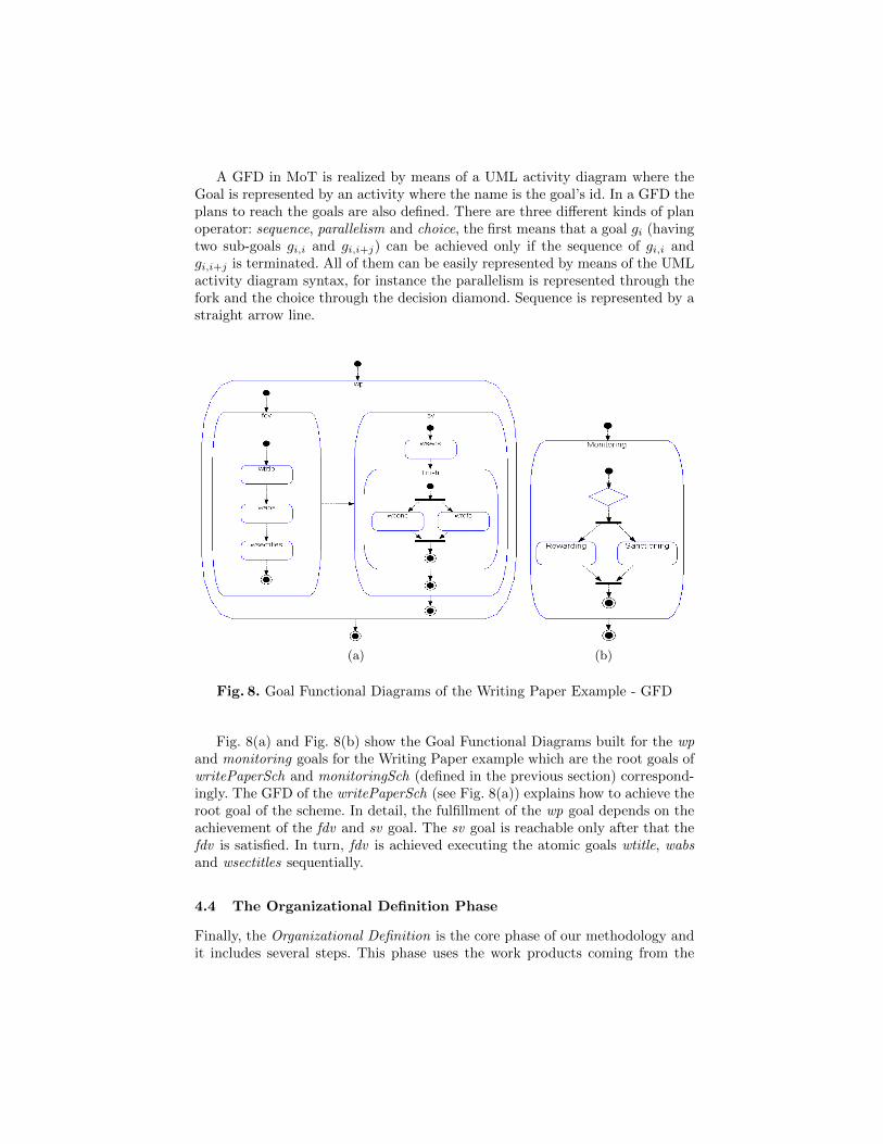
A GFD in MoT is realized by means of a UML activity diagram where theGoal is represented by an activity where the name is the goal’s id. In a GFD theplans to reach the goals are also defined. There are three different kinds of planoperator: sequence, parallelism and choice, the first means that a goal gi (havingtwo sub-goals gi,i and gi,i+j) can be achieved only if the sequence of gi,i andgi,i+j is terminated. All of them can be easily represented by means of the UMLactivity diagram syntax, for instance the parallelism is represented through thefork and the choice through the decision diamond. Sequence is represented by astraight arrow line.
(a) (b)
Fig. 8. Goal Functional Diagrams of the Writing Paper Example - GFD
Fig. 8(a) and Fig. 8(b) show the Goal Functional Diagrams built for the wpand monitoring goals for the Writing Paper example which are the root goals ofwritePaperSch and monitoringSch (defined in the previous section) correspond-ingly. The GFD of the writePaperSch (see Fig. 8(a)) explains how to achieve theroot goal of the scheme. In detail, the fulfillment of the wp goal depends on theachievement of the fdv and sv goal. The sv goal is reachable only after that thefdv is satisfied. In turn, fdv is achieved executing the atomic goals wtitle, wabsand wsectitles sequentially.
4.4 The Organizational Definition Phase
Finally, the Organizational Definition is the core phase of our methodology andit includes several steps. This phase uses the work products coming from the
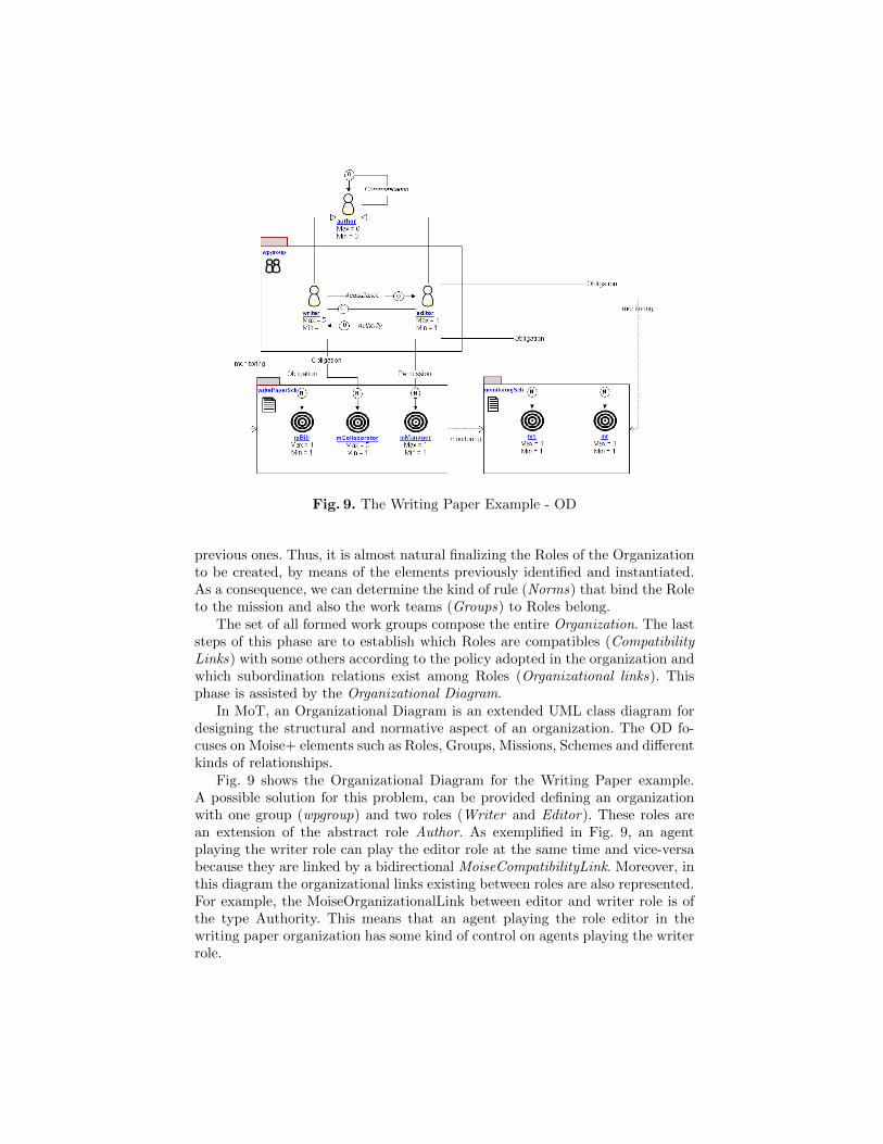
Fig. 9. The Writing Paper Example - OD
previous ones. Thus, it is almost natural finalizing the Roles of the Organizationto be created, by means of the elements previously identified and instantiated.As a consequence, we can determine the kind of rule (Norms) that bind the Roleto the mission and also the work teams (Groups) to Roles belong.
The set of all formed work groups compose the entire Organization. The laststeps of this phase are to establish which Roles are compatibles (CompatibilityLinks) with some others according to the policy adopted in the organization andwhich subordination relations exist among Roles (Organizational links). Thisphase is assisted by the Organizational Diagram.
In MoT, an Organizational Diagram is an extended UML class diagram fordesigning the structural and normative aspect of an organization. The OD fo-cuses on Moise+ elements such as Roles, Groups, Missions, Schemes and differentkinds of relationships.
Fig. 9 shows the Organizational Diagram for the Writing Paper example.A possible solution for this problem, can be provided defining an organizationwith one group (wpgroup) and two roles (Writer and Editor). These roles arean extension of the abstract role Author. As exemplified in Fig. 9, an agentplaying the writer role can play the editor role at the same time and vice-versabecause they are linked by a bidirectional MoiseCompatibilityLink. Moreover, inthis diagram the organizational links existing between roles are also represented.For example, the MoiseOrganizationalLink between editor and writer role is ofthe type Authority. This means that an agent playing the role editor in thewriting paper organization has some kind of control on agents playing the writerrole.

SEE FIG. 9SSG
Fig. 10. Moise+ Structural Specification generated code from OD
Finally, the instantiated roles are linked by means of MoiseNormLinks torelated missions. In the portion of diagram reported in Fig. 9, one of the Writer ’smission is mbib (i.e. getting references for the paper). The norm linking thatmission to the role is an Obligation, that is the agent playing the Writer rolemust commit to this mission. The Editor, instead, may commit to the missionmManager because the link is a Permission norm.
4.5 Code Generation Phase
The last phase of our process is the Code Generation. This phase is devoted toproduce the Moise+ organizational specifications of the MAS to be developed.MoT supports this phase generating Moise+ code automatically.
In the previous sections we have defined the domain-specific modeling lan-guage in order to design agent organizations to be implemented in Moise+. Theresulting metamodel containing the domain concepts with their relations andnotation is shown in Fig.3. In this subsection, instead, we want to specify themapping from model to code by defining a domain-specific code generator us-ing MetaEdit+. In MetaEdit+, code generators are defined in the GeneratorEditor using the MERL scripting language. MERL enables navigating throughthe elements of the user designed diagrams accessing the data according to thedefined metamodel. Moreover, MERL allows translating the design data into theformats required by the generation target language.
For our purposes, we have defined the main generators associated with thediagram types defined in the section 3.1. Each generator is responsible of pro-ducing a Moise+ specification portion.
Specifically, the Structural Specification Generator (SSG) and the NormativeSpecification Generator (NSG) produces the XML portion of code concerningthe Moise+ Structural and Normative Specification by respectively analyzingthe elements designed in the Organizational Diagram.
The Functional Specification Generator (FSG) generates the Moise+ Func-tional Specification. This (as hinted in the section 2) shows how the organiza-tional goals can be reached and how to compose the missions to be assigned to aspecific role. For these reasons, the FSG is obtained merging two sub-generators:the former maps of the Goal Functional Diagram in the XML code concerningthe Moise+ goal decomposition tree; the latter traduces the design data of theScheme Structural Diagram in the portion of XML code representing the com-position of the missions. The Fig. 10 shows the portion of structural specificationgenerated by means of application of SSG to the OD of the writing paper exam-ple.
5 Conclusion
In order to fully exploit the powerful of agents nowadays research is directingtowards multi agent systems organized in the same way the humans do. Thedesign and implementation of this kind of system obviously requires to manageabstractions that have to be used for modeling norms, goals, social schemes adso on. Above all it requires supporting tools for guiding the designer from theanalysis to the implementation in simple and less costly fashion.
This paper introduce a first step towards the creation of a design process fordeveloping MASs organized in hierarchical structures that can be implementedwith Moise+ and supported by a CASE tool using a specific notation for repre-senting organizations. In particular, we illustrated a portion of our methodolog-ical approach devoted to instantiate the main elements necessary to create anagent organization with Moise+.
Moreover, we developed a CASE tool by using Metaedit+ that allows togenerate specific code for each kind of diagrams, in so doing we are able tosupport the designer in producing organizational multi agent systems models andthen implementing them in a semi automatic way. The Moise+ metamodel is thebasis for our tool that, thanks to automatic generation of code from diagrams,lets the designer free from the heavy work related to the manual production oforganization XML code.
Finally it is worth noting that the use of Metaedit+ constitutes a first ex-periment that produced very good results in terms of CASE tool for supportingdesign activities. The approach we adopted for the creation of the UML profilefor representing organizations is general enough for being applied with every kindof tools since it is grounded on the creation of a metamodel that complementthe one of Moise+ with that of UML.
For the future we are planning to develop a CASE tool as an extension ofEclipse that might let us overcome the age-old limit of Metaedit+ in managingimages and easily positioning elements in the diagrams.
Acknowledgment. This work was realized within IMPULSO and partially sup-ported by the EU project FP7-Humanobs and by the FRASI project.
References
1. Raphael H. Bordini, Jomi Fred Hubner, and Michael J. Wooldridge. Programmingmulti-agent systems in AgentSpeak using Jason. Wiley-Interscience, 2007.
2. Paolo Bresciani, Paolo Giorgini, Fausto Giunchiglia, John Mylopoulos, and AnnaPerini. Tropos: An agent-oriented software development methodology. AutonomousAgent and Multi-Agent Systems (8), 3:203–236, 2004.
3. M. Cossentino, N. Gaud, V. Hilaire, S. Galland, and A. Koukam. ASPECS: anagent-oriented software process for engineering complex systems. AutonomousAgents and Multi-Agent Systems, 20(2):260–304, 2010.
4. V. Dignum and F. Dignum. Modelling agent societies: co-ordination frameworksand institutions. Progress in Artificial Intelligence, pages 7–21, 2001.
5. K. Fischer, M. Schillo, and J. Siekmann. Holonic multiagent systems: A foundationfor the organisation of multiagent systems. Holonic and Multi-Agent Systems forManufacturing, pages 1083–1084, 2004.
6. Isazadeh H. and Lamb D. A. Case environments and metacase tools. 1997.7. Jomi Fred Hubner. J-moise+ programming organizational agents with moise+ and
jason (2007).8. Jomi Fred Hubner, Jaime Simao Sichman, and Olivier Boissier. Moise tutorial.
(for moise 0.7).9. Jomi Fred Hubner, Jaime Simao Sichman, and Olivier Boissier. Moise+: towards
a structural, functional, and deontic model for mas organization. In Proceedingsof the first international joint conference on Autonomous agents and multiagentsystems: part 1, page 502. ACM, 2002.
10. Jomi Fred Hubner, Jaime Simao Sichman, and Olivier Boissier. Developing or-ganised multiagent systems using the MOISE+ model: programming issues at thesystem and agent levels. International Journal of Agent-Oriented Software Engi-neering, 1(3):370–395, 2007.
11. Douglas C. Schmidt. Model-driven engineering. Computer, 39(2):25–31, Feb. 2006.12. Juha-Pekka Tolvanen and Matti Rossi. Metaedit+: defining and using domain-
specific modeling languages and code generators. In OOPSLA ’03: Companionof the 18th annual ACM SIGPLAN conference on Object-oriented programming,systems, languages, and applications, pages 92–93, New York, NY, USA, 2003.ACM Press.
13. M. Wooldridge and N.R. Jennings. Intelligent Agents: Theory and Practice. TheKnowledge Engineering Review, 10(2):115–152, 1995.
14. M. Woolridge and M.J. Wooldridge. Introduction to Multiagent Systems. JohnWiley & Sons, Inc. New York, NY, USA, 2001.
15. E. Yu. Modeling organizations for information systems requirements engineer-ing. Requirements Engineering, Proceedings of IEEE International Symposium on(1993):34–41, 1993.
16. Franco Zambonelli, Nicholas R. Jennings, and Michael Wooldridge. Developingmultiagent systems: The Gaia methodology. ACM Transactions on Software En-gineering and Methodology (TOSEM), 12(3):317–370, July 2003.