towards megaco architecture
TRANSCRIPT

8/13/2019 Towards Megaco Architecture
http://slidepdf.com/reader/full/towards-megaco-architecture 1/10
Towards Megaco Architecture
J. Peltola, J. Aromaa, A. Mustonen
Satakunta Polytechnic
November 28th 2002
Abstract —The Voice over Internet Protocol (VoIP)
technology is designed to transfer voice, video and data in
packet based networks. As it stands this technology is not
suitable for traditional circuit switched networks. To
combine these two network techniques, the packet
network and the circuit switched network, a new network
architecture is needed. The aim of this paper was to
examine the development of combining the VoIP
technology and traditional phone networks. Special
attention was given to protocols associated with thisconvergence. In this paper ITU-T H.323 and IETF SIP
(Session Initiation Protocol) VoIP protocols are studied.
These protocols were the base when studying call control
protocol called Megaco/H.248 in next generation networks.
Megaco/H.248 is a media gateway control protocol and it
is a collaborative effort of the IETF and ITU-T. Megaco
specifies the master/slave architecture for decomposed
gateways. Media Gateway Controller (MGC) is the master
server which is responsible for call control functions and
one or more Media Gateways (MG) are the slave clients
which are responsible for media mixing. This paper
describes how Megaco solutions will take place at
Satakunta Polytechnic. The operation of the
Megaco/H.248 protocol is described with examples.
Index Terms —Voice over IP, Megaco, Network
Convergence
I. INTRODUCTION
V OICE traffic is more and more general payload type
in packet networks. There is a demand for
combining the modern public switched telephone
network (PSTN) and VoIP-technologies in the packet
networks. As it stands VoIP solutions like SIP and
H.323 do not work in the PSTN. To combine these twonetwork architectures a new kind of architecture is
defined. ITU-T and IETF created a protocol for
controlling Media Gateways. This new protocol creates
a new architecture called Megaco architecture which
makes it possible to use services in two different
networks. Centralized control enables an easy way to
provide customers with new services.
The idea of a decomposed gateway architecture is
based on the ETSI TIPHON project
(Telecommunication and Internet Protocol
Harmonization Over Networks) [9]. TIPHON defines
five scenarios of how to combine two networks andhow to make calls between these two networks.
TIPHON project defines Interworking Functions (IWF)
which include Signaling Gateway, Media Gateway and
Media Gateway Controller.
The Megaco protocol controls Media Gateway. So
this Megaco/H.248 [4] protocol works between the
Media Gateway Controller (MGC) and the Media
Gateway (MG). This kind of network is easy to expand
because all the intelligence is stored in the MGC.
Signaling from and to the PSTN is transported through
the Signaling Gateway (SG). The protocol used to
transport signaling information in the packet network is
Signaling Control Transport Protocol (SCTP) [12].
This paper describes a decomposed gateway
architecture and how to combine VoIP signaling
protocols like SIP and H.323 to this new network. The
paper is organized as follows: Section 2 gives an
overview of VoIP protocols, like H.323 and SIP;
Section 3 describes the Megaco Architecture and
Megaco protocol; Section 4 presents how to combine
the PSTN and packet networks and how these networks
work together; Section 5 describes the Megaco solution
at Satakunta Polytechnic; Section 6 describes future
plans and Section 7 is the conclusion part.
II. VOIP STANDARDS
The VoIP technology started to develop more rapidly
after 1995. That year VocalTec introduced Internet
telephony software [1]. This PC based program opened
connection between two PC endpoints across the
Internet. The ITU-T study group 16 prepared a VoIP
standard called H.323 [2]. This standard completed in
1996. The IETF VoIP standard called Session Initiation
Protocol (SIP) was ready to be published in 1999. SIP is
a text based protocol and it was first defined in the RFC2543 [3]. In the year 2000 ITU-T and IETF
collaboratively published the Megaco protocol for
controlling Media Gateways.
A. H.323
The H.323 protocol was designed to support
multimedia services over a LAN (Local Area Network).
H.323 is an umbrella standard and it includes H.245 for
control operations, H.225 for connection management
and T.120 for document support for conferences. H.323
uses a binary syntax for its messages as several other
ITU-T standards do.
The H.323 architecture defines four majorcomponents: Terminals, Gateways, Multi-point Control
43

8/13/2019 Towards Megaco Architecture
http://slidepdf.com/reader/full/towards-megaco-architecture 2/10
Units (MCU) and Gatekeepers. The H.323 terminal
provides real-time, two-way audio, video and data
communications with another H.323 terminal. Examples
of the H.323 terminals are the multimedia PC or the IP
phone. H.323 requires that terminals must have voice
functionality and ability to communicate using the
H.225 and H.245 protocols. The Gateway provides the
appropriate translation between transmission formats(for example H.225.0 to/from H.221) and between
communications procedures. The Gateway also
performs call setup and clearing on both the packet
network side and the PSTN side. This makes the H.323
Gateway a very important component when connecting
traffic between the PSTN and the packet network. The
Gatekeeper, which is optional in an H.323 system,
provides call control services to the H.323 endpoints.
There is only one Gatekeeper in one Zone, and this
Gatekeeper performs all call control functions inside
this Zone. The Gatekeeper may also do for example
address translations and bandwidth management. The
MCU supports multipoint conferencing between three
or more terminals and Gateways. The MCU consists of
a multipoint controller (MC) and a multipoint processor
(MP). The MC carries out the capabilities exchange
with each endpoint in a multipoint conference. The MP
processes these media streams and returns them to the
endpoints. Major H.323 components and examples of
connections to other networks are described in Fig. 1.
[5]
There may be two types of network servers in the SIP
environment: a proxy server and a redirect server. The
SIP proxy server acts as both a server and a client for
making requests on behalf of other clients. A SIP
redirect server is a user agent server that dictates the
client to contact an alternate address. Another
component in SIP is a registration server called
Registrar. The Registrar is a server that acceptsregistration requests. The Registrar is typically co-
located with a proxy or redirect server. The Registrar
may offer location services on the base of register
messages. The SIP components are presented in Fig. 2.
[6] The SIP and H.323 standards are used for signaling
in the VoIP networks. These protocols make it possible
to create, modify and terminate multimedia calls. Both
of these VoIP network architectures contain intelligent
components. Thus the architectures are based on
distributed intelligence. This kind of architecture is
difficult to maintain but flexible when adding
intelligence to endpoints or gateways. Developers on
the PSTN side think that this kind of architecture which
is based on distributed intelligence is complex. [7]
B. SIP
The Session Initiation Protocol (SIP) is anapplication-layer control protocol that can establish,
modify, and terminate multimedia sessions
(conferences) such as Internet telephony calls. SIP can
also invite participants to already existing sessions, such
as multicast conferences. SIP uses text-encoded
messages for request and responses like HTTP. SIP
consists of two major components, which are the user
agent and the network server. The user agent (UA) is a
logical entity that can act as both a user agent client
(UAC) and a user agent server (UAS). The UA
interfaces with the user and acts on behalf of the user.
The UAC initiates the call and the UAS is used to
answer the call.
IPIP
IPIP
SIP User Agent
SIP Proxy Server
and Registrar
SIP Redirect Server
IPIP
SIP User Agent
SIP ProxyServer
IPIP
IPIP
SIP User Agent
SIP Proxy Server
and Registrar
SIP Redirect Server
IPIP
SIP User Agent
SIP ProxyServer
Fig. 2: Major SIP components
PSTNPSTNIPIP
H.323 Gateway
H.323 Terminals
H.323 Gatekeeper
MCU
H.323 Gateway
ATMATM
Fig. 1: An example of the H.323 network
III. MEDIA GATEWAY CONTROL
The Media Gateway Control concept means ways to
control the device which manipulates and terminates the
media streams. These devices are called Media
Gateways (MG). This concept also means that there is
one component which includes the network intelligence.
The control functions and intelligence are made by theMedia Gateway Controller (MGC). The protocol which
is used for controlling MGs is called Megaco/H.248. [8]
The Megaco/H.248 standard is the result of the
cooperation between IETF and ITU-T. Lots of other
organizations helped gain this coal. The ETSI TIPHON
project and the Multiservice Switching Forum (MSF)
were significant when this protocol was being
developed. Previous versions of Media Gateway
Control Protocols have been introduced since 1998.
Simple Gateway Control Protocol (SGCP) was the first
protocol for controlling Gateways. Also Internet
Protocol Device Control (IPDC) was announced in1998. These two protocols combined and the resulting
44

8/13/2019 Towards Megaco Architecture
http://slidepdf.com/reader/full/towards-megaco-architecture 3/10
protocol was named Media Gateway Control Protocol
(MGCP). ITU-T made Media Device Control Protocol
(MDCP) as a competing proposal for the MGCP. ITU
renamed the MDCP to H.GCP. Finally a new kind of
connection model was developed and the
Megaco/H.248 development began. Megaco/H.248 was
approved by IESG in May 2000 and by the ITU-T in
June 2000. [8]
The concentration of Interworking functionality
consists of three decomposed devices. This is because
one device with all functions needed for Interworking is
not scalable or efficient enough. The three components
are: [9]
- Media Gateway (MG) handling the conversion and
mixing of the media streams
- Media Gateway Controller (MGC) managing and
controlling the connections and providing call
processing and
- Signaling Gateway (SG) providing the signaling
mediation function.
These decomposed components are shown in Fig. 3.
The decomposition offers advantages such as
efficiency, robustness, flexibility and scalability. The
intelligence for call control logic and network signaling
is moved to more generic computing resources (MGC).
The MGC allows the network operator tightly to control
and manage the communications and to provide new
services for customers without making any changes to
MGs. [10]
When different functionalities take place in different
components a special protocol between the components
is needed. The Megaco protocol addresses the MGC↔
MG communication. Signaling information from and to
the PSTN is carried out using the SCTP [12] as a
signaling transport protocol. Section 4 describes more
accurately the communication between the MGC and
the MG. Fig. 4 shows the VoIP network, the PSTN and
the decomposed Gateways which mix media streams
between these two networks. The call control protocol
Megaco is also mentioned. [10]
IV. MEGACO/H.248 PROTOCOL
The Megaco/H.248 protocol is a master/slave
protocol. In this architecture the MGC is a master and
one or more MGs are slaves. The Megaco protocol
provides means for describing and controlling the
connections of media streams. The Megaco/H.248
protocol is based on a connection model. The
connection model includes two concepts: Contexts and
Terminations. The connection model can be
manipulated via commands and extended with specific
packages. [4], [10]
PSTNPSTN IPIPVoIP
Terminal
P C M
Telephone
Exchange
Subscriber MG
SGSignaling (ISUP)
S C T P
M e g a c
o / H. 2 4 8
MGC
MGRTP
H .3 2 3 o r S I P
R T P
M e g a c o / H
. 2 4 8
Fig.4: Gateway distribution and control
Termination
RTP Stream
Termination
SCN Bearer
Channel
Context
Context
Context
Termination
RTP Stream
Termination
RTP Stream
Termination
SCN Bearer
Channel
Termination
SCN Bearer
Channel
Termination
SCN Bearer
Channel
Null Context
*
*
*
Media Gateway
Termination
RTP Stream
Termination
SCN Bearer
Channel
Context
Context
Context
Termination
RTP Stream
Termination
RTP Stream
Termination
SCN Bearer
Channel
Termination
SCN Bearer
Channel
Termination
SCN Bearer
Channel
Null Context
*
*
*
Media Gateway
Termination
RTP Stream
Termination
SCN Bearer
Channel
Context
Context
Context
Termination
RTP Stream
Termination
RTP Stream
Termination
SCN Bearer
Channel
Termination
SCN Bearer
Channel
Termination
SCN Bearer
Channel
NullContext
*
*
*
Media Gateway
Fig.5: Example of Connection Model described in Megaco/H.248
standard
SG
MGC
MG
Media ControlSignal ing Control
Fig. 3: Physical decomposition of MG, MGC and SG
A. The Connection Model
The connection model for the Megaco protocoldescribes the logical entities within the MG that can becontrolled by the MGC. The main abstractions used inthe connection model are Terminations and Contexts.[4]
A Termination sources and/or sinks one or morestreams. In a multimedia conference, a Termination can be multimedia and sources or sinks multiple mediastreams. [4]
A Context is an association between a collection ofTerminations. It describes the topology (who hears/seeswhom) of associated Terminations and the mediamixing if more than one Terminations are involved inthe association. There is a special type of Context, thenull Context, which contains all Terminations that arenot associated to any other Termination (e.g. idle linesin the access gateway). These concepts are shown inFig. 5. [4]
45

8/13/2019 Towards Megaco Architecture
http://slidepdf.com/reader/full/towards-megaco-architecture 4/10
Terminations can be permanent or ephemeral.
Permanent Terminations represent physical entities
which have a semi-permanent existence for example
Termination representing a TDM (Time Division
Multiplexing) channel. The Terminations representing
ephemeral information flows would usually exist only
for the duration of their use (e.g. RTP flows).
Ephemeral Terminations are created by the Addcommand and destroyed by the Subtract command. A
physical Termination is added to or subtracted from a
Context; it is taken from or to the Null Context. [4]
Termination is identified by a unique ID called
TerminationID. The Termination is described by
Properties, Signals, Events and Statistics. Terminations
may have signals applied to them. Signals are MG
generated media streams such as tones and
announcements as well as line signals such as
hookswitch. Properties can be common or specific to
media streams. Properties are grouped into a set of
Descriptors that are included in commands.
Terminations may be programmed to detect Events
which can trigger notification messages to the MGC, or
action by the MG can also trigger notification to the
MGC. Statistics may be accumulated on a Termination
and reported to the MGC. [4], [10]
B. Command
The protocol provides commands for manipulating
Contexts and Terminations which are the logical entities
of the connection model. For example, with the Add
command it is possible to add Terminations to a
Context, the Modify command makes it possible to
modify Terminations, the Subtract command subtracts
Terminations from a Context, and the AuditValue and
the AuditCapabilities makes it possible to audit
properties of Contexts or Terminations. The commands
provide for complete control of the properties of
Contexts and Terminations. This includes specifying
which events a Termination is to report, which signals
are to be applied to a Termination and specifying the
topology of a Context. Most commands are for the
specific use of the MGC as a command initiator in
controlling MGs as command responders. The
exceptions are the Notify and ServiceChange
commands. Commands, their explanations and
directions are presented in Table I. [4]
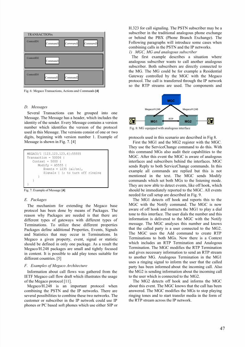
C. Transactions
The Commands between the Media Gateway
Controller and the Media Gateway are grouped into
Transactions. The Transactions are identified by a
unique TransactionID. Transactions consist of one or
more Actions. An Action consists of a series of
Commands that are limited to operating within a single
Context. Actions are recognized by ContextID. The
relationship between Transactions, Actions and
Commands is shown in Fig. 6. [4]
Every transaction is initiated by a TransactionRequest
and must be closed by a TransactionReply. There is a
way to prevent the sender from assuming that the
TransactionRequest was lost and the Transaction will
take some time to complete. A TransactionPending
indicates that the Transaction is actively being
processed, but has not been completed. [4]
TABLE I
MEGACO COMMANDS
Command EXPLANATION Direction
Add Command adds a
Termination to a Context.
The Add command on the
first Termination in a
Context is used to create a
Context.
MGC - MG
Modify Command modifies the
properties, events and
signals of a Termination.
MGC - MG
Subtract Command disconnects a
Termination from its
Context and returns
statistics on the
Termination's participationin the Context. The
Subtract command on the
last Termination in a
Context deletes the
Context.
MGC - MG
Move Command atomically
moves a Termination to
another Context.
MGC - MG
AuditValue Command returns the
current state of properties,
events, signals and
statistics of Terminations.
MGC - MG
AuditCapabilities Command returns all the
possible values for
Termination properties,
events and signals allowed by the MG.
MGC - MG
Notify Command allows the MG
to inform the MGC of the
occurrence of events in the
MG.
MG - MGC
ServiceChange The ServiceChange
command allows the MG
to notify the MGC that a
Termination or group of
Terminations is about to be
taken out of service or has
just been returned to
service.
MGC - MG
MG - MGC
46
8/13/2019 Towards Megaco Architecture
http://slidepdf.com/reader/full/towards-megaco-architecture 5/10
MEGACO/1 [123.123.123.4]:55555
Transaction = 50006 {
Context = 5000 {
Modify = A5555 {
Events = 1235 {al/on},
Signals { }; to turn off ringing
}
}
}
Fig. 7: Example of Message [4]
D. Messages
Several Transactions can be grouped into one
Message. The Message has a header, which includes the
identity of the sender. Every Message contains a versionnumber which identifies the version of the protocol
used in this Message. The versions consist of one or two
digits, beginning with version number 1. Example of
Message is shown in Fig. 7. [4]
E. Packages
The mechanism for extending the Megaco base
protocol has been done by means of Packages. The
reason why Packages are needed is that there are
different types of gateways with different types of
Terminations. To utilize these different properties
Packages define additional Properties, Events, Signals
and Statistics that may occur in Terminations. In
Megaco a given property, event, signal or statistic
should be defined in only one package. As a result theMegaco/H.248 packages are small and tightly focused
in content. It is possible to add play tones suitable for
different countries. [5]
F. Examples of Megaco Architecture
Information about call flows was gathered from the
IETF Megaco call flow draft which illustrates the usage
of the Megaco protocol [11].
Megaco/H.248 is an important protocol when
combining the PSTN and the IP networks. There are
several possibilities to combine these two networks. The
customer or subscriber in the IP network could use IP
phones or PC based soft phones which use either SIP or
H.323 for call signaling. The PSTN subscriber may be a
subscriber in the traditional analogous phone exchange
or behind the PBX (Phone Branch Exchange). The
Following paragraphs will introduce some cases when
combining calls in the PSTN and the IP networks.Command1
ContextID1
ContextID3
ContextID2
Command1
TRANSACTIONx
Command1 Command3
Command2Command1
Command1ContextID1
ContextID3
ContextID2
Command1
TRANSACTIONx
Command1 Command3
Command2Command1
Fig. 6: Megaco Transactions, Actions and Commands [4]
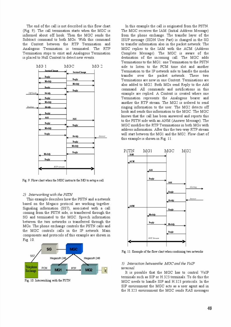
1) MGC, MG and analogous subscriber
The first example describes a situation where
analogous subscriber wants to call another analogoussubscriber. Both subscribers are directly connected to
the MG. The MG could be for example a Residential
Gateway controlled by the MGC with the Megaco
protocol. The call is transferred through the IP network
so the RTP streams are used. The components and
protocols used in this scenario are described in Fig 8.
MG1
MGC
MG2
Megaco/H.248Megaco/H.248
RTP
Fig. 8: MG equipped with analogous interface
First the MG1 and the MG2 register with the MGC.
They use the ServiceChange command to do this. With
this command MGs also audit their capabilities to the
MGC. After this event the MGC is aware of analogous
interfaces and subscribers behind the interfaces. MGC
sends Reply to both ServiceChange commands. In this
example all commands are replied but this is not
mentioned in the text. The MGC sends Modify
commands which set both MGs to the listening mode.They are now able to detect events, like off hook, which
should be immediately reported to the MGC. All events
needed for call setup are described in Fig. 9.
The MG1 detects off hook and reports this to the
MGC with the Notify command. The MGC is now
aware of off hook and instructs the MG1 to play a dial
tone to this interface. The user dials the number and this
information is delivered to the MGC with the Notify
message. The MGC analyses this number and knows
that the called party is a user connected to the MG2.
The MGC uses the Add command to create RTP
Terminations to both MGs. Now there is a Context
which includes an RTP Termination and AnalogousTermination. The MGC modifies the RTP Termination
and gives necessary information to send an RTP stream
to another MG. Analogous Termination in the MG1
uses a ringing signal to inform the user that the called
party has been informed about the incoming call. Also
the MG2 is sending information about the incoming call
to the user which is connected to the MG2.
The MG2 detects off hook and informs the MGC
about this event. The MGC knows that the call has been
answered. The MGC modifies the MGs to stop playing
ringing tones and to start transfer media in the form of
the RTP stream across the IP network.
47
8/13/2019 Towards Megaco Architecture
http://slidepdf.com/reader/full/towards-megaco-architecture 6/10
8/13/2019 Towards Megaco Architecture
http://slidepdf.com/reader/full/towards-megaco-architecture 7/10
to Gatekeeper to establish the call. In these cases the
intelligence is situated in VoIP terminals and in the
MGC. The VoIP terminals and the MGC are able to
handle call signaling and call control functions. SIP
interaction with the MGC is presented in Fig.12. Fig. 13
presents the interaction with the H.323 environment.
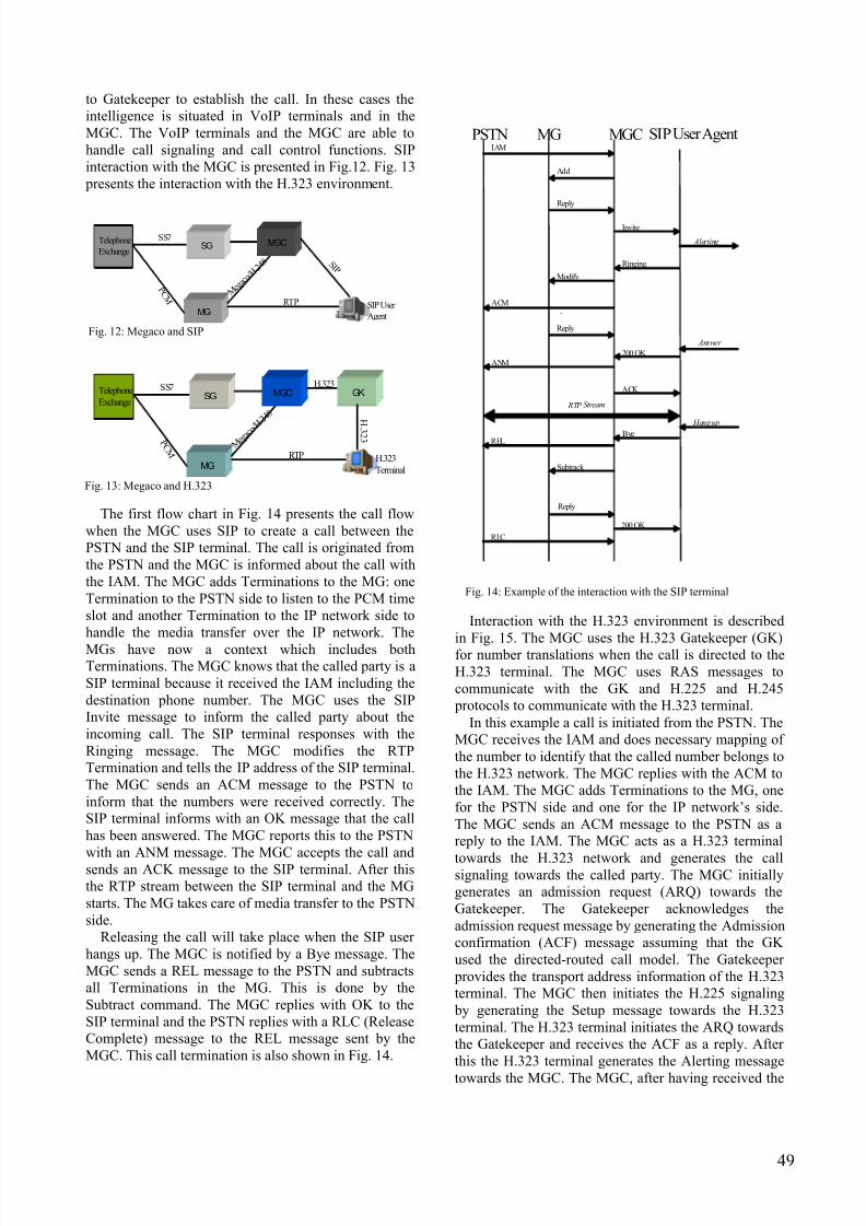
The first flow chart in Fig. 14 presents the call flow
when the MGC uses SIP to create a call between the
PSTN and the SIP terminal. The call is originated from
the PSTN and the MGC is informed about the call with
the IAM. The MGC adds Terminations to the MG: one
Termination to the PSTN side to listen to the PCM time
slot and another Termination to the IP network side to
handle the media transfer over the IP network. The
MGs have now a context which includes bothTerminations. The MGC knows that the called party is a
SIP terminal because it received the IAM including the
destination phone number. The MGC uses the SIP
Invite message to inform the called party about the
incoming call. The SIP terminal responses with the
Ringing message. The MGC modifies the RTP
Termination and tells the IP address of the SIP terminal.
The MGC sends an ACM message to the PSTN to
inform that the numbers were received correctly. The
SIP terminal informs with an OK message that the call
has been answered. The MGC reports this to the PSTN
with an ANM message. The MGC accepts the call andsends an ACK message to the SIP terminal. After this
the RTP stream between the SIP terminal and the MG
starts. The MG takes care of media transfer to the PSTN
side.
Releasing the call will take place when the SIP user
hangs up. The MGC is notified by a Bye message. The
MGC sends a REL message to the PSTN and subtracts
all Terminations in the MG. This is done by the
Subtract command. The MGC replies with OK to the
SIP terminal and the PSTN replies with a RLC (Release
Complete) message to the REL message sent by the
MGC. This call termination is also shown in Fig. 14.
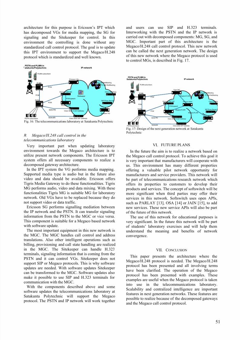
Interaction with the H.323 environment is described
in Fig. 15. The MGC uses the H.323 Gatekeeper (GK)for number translations when the call is directed to the
H.323 terminal. The MGC uses RAS messages to
communicate with the GK and H.225 and H.245
protocols to communicate with the H.323 terminal.
PSTN MG MGC SIP User IAM
ACM -
Add
Reply
Invite
Ringing
Alerting
Answer
200 OK
ACK
ANM
Modify
Reply
200 OK
RTP Stream
Bye REL
Subtrack
Reply
RLC
Hang up
Agent
Fig. 14: Example of the interaction with the SIP terminal
P C M
Telephone
Exchange
Telephone
Exchange
MG
SGSS7
M e g a c o /
H. 2 4 8
MGC
RTP
H.323GK
H.323
Terminal
H
. 3 2 3
Fig. 13: Megaco and H.323
P C M
Telephone
Exchange
Telephone
Exchange
MG
SGSS7
M e g a c o / H. 2 4 8
MGC
RTP SIP User
Agent
S I P
Fig. 12: Megaco and SIP
In this example a call is initiated from the PSTN. The
MGC receives the IAM and does necessary mapping of
the number to identify that the called number belongs to
the H.323 network. The MGC replies with the ACM to
the IAM. The MGC adds Terminations to the MG, one
for the PSTN side and one for the IP network’s side.
The MGC sends an ACM message to the PSTN as a
reply to the IAM. The MGC acts as a H.323 terminal
towards the H.323 network and generates the callsignaling towards the called party. The MGC initially
generates an admission request (ARQ) towards the
Gatekeeper. The Gatekeeper acknowledges the
admission request message by generating the Admission
confirmation (ACF) message assuming that the GK
used the directed-routed call model. The Gatekeeper
provides the transport address information of the H.323
terminal. The MGC then initiates the H.225 signaling
by generating the Setup message towards the H.323
terminal. The H.323 terminal initiates the ARQ towards
the Gatekeeper and receives the ACF as a reply. After
this the H.323 terminal generates the Alerting message
towards the MGC. The MGC, after having received the
49

8/13/2019 Towards Megaco Architecture
http://slidepdf.com/reader/full/towards-megaco-architecture 8/10
Alerting message from the H.323 Endpoint, generates
an ACM message to the PSTN.
These examples help understand the function of the
Megaco protocol in a discomposed architecture. It is
also important that the MGC can handle calls which use
the SIP or H.323 protocols. The MGC acts as a phone
exchange in the IP network but the switching part is
distributed to several MGs.
The H.323 terminal sends the Connect message when
the called party off hooks. The Terminal Capability set
and the master/slave determination occurs between the
MGC and the H.323 terminal. The Open Logical
channels messages indicate the session and media
related parameters. The MGC generates a Modifymessage towards the MG to modify the RTP
Termination with address information. After this the
RTP stream starts between the MG and the H.323
terminal.
V. MEGACO SOLUTION AT SATAKUNTA POLYTECHNIC
Satakunta Polytechnic has a very versatile
telecommunications laboratory. There are several
possibilities to combine the PSTN and IP networks.
This convergence is done by using intelligent gateways.
There is a need for centralized intelligence which can
handle calls coming from SIP and H.323 networks and
going to the PSTN and vice versa.
The call termination takes place when the H.323
terminal goes on hook. The MGC initiates the tearing
down of the call by closing the logical channels that
were earlier created for exchanging the H.245
information (Close Logical Channels). After receiving
the Release Complete message the MGC generates a
REL message to the PSTN. The MGC generates a
Disengage Request (DRQ) towards the Gatekeeper. The
Gatekeeper acknowledges the Disengage Request
message by generating the Disengage Confirmation
(DCF) message. After this the MG subtracts the two
Terminations from the Context. The context itself is
deleted when the last Termination is subtracted.
A. Laboratory environment without the Megaco/H.248
call control
The telecommunications laboratory at SatakuntaPolytechnic is described in Fig. 16. There is a fixed
network telephone exchange (Nokia DX220) in the
laboratory. This represents the PSTN. This exchange is
connected to a public land mobile network (PLMN).
The PLMN includes a mobile switching centre (MSC,
Nokia DX 200) with an integrated visitor location
register (VLR) and a home location register (HLR), a
base station controller (BSC, Siemens) and two base
transceiver stations (BTS, Siemens).
PSTN MG MGC GK
IAM
ACM
Add
Reply
ANM
Reply
RTP Stream
REL
Reply
RLC
H.323 Terminal
ARQ
ACF
Setup
ARQ
ACF
Connect
Terminal Capability Set
Master Slave Determination
Open Logical Channels
Modify
Alerting
Close Logical Channels
Release Complete
DRQ
DCF
DRQ
DCF
Subtract
Fig. 15: Example of the interaction with the H.323 environment
The IP network contains components from several
manufacturers. The H.323 environment is based on
Cisco System Gatekeeper and Gateway. Microsoft NetMeeting is an H.323 terminal in the H.323
environment. Connection to the PSTN goes through
Cisco 3640 Gateway. The Gateway is equipped with an
E1 interface. This enables 30 simultaneous calls to the
PSTN. The SIP environment is based on the Columbia
University SIP server. The connection to the PSTN is
arranged through Cisco 2620 Gateway using the ISDN
2B+D connection. Cisco 7960 VoIP phones represent
the SIP terminals.
The Ericsson IP Telephony (IPT) system includes
Signaling Gateway, three Voice Gateways (VG) and
Sitekeeper. The SG provides signalling mediation between the IP network and the PSTN. The VG
provides media mixing between the PCM signal and
packet network. The Sitekeeper provides call control
functions to the IPT system. The Sitekeeper can also act
as a Gatekeeper for H.323 terminals. The IPT system
provides trunk replacement e.g. it is possible to call
from the PSTN to the PLMN and the media is
transferred in the IP network.
As seen above, there are several different
architectures in the telecommunications laboratory at
Satakunta Polytechnic. To combine these architectures
one intelligent component is needed to handle the
calling and signaling information which comes from thePSTN, SIP or H.323 networks. The most suitable
50
8/13/2019 Towards Megaco Architecture
http://slidepdf.com/reader/full/towards-megaco-architecture 9/10
architecture for this purpose is Ericsson’s IPT which
has decomposed VGs for media mapping, the SG for
signaling and the Sitekeeper for control. In this
environment the controlling is done without any
standardized call control protocol. The goal is to update
this IPT environment to support the Megaco/H.248
protocol which is standardized and well known.
B. Megaco/H.248 call control in the
telecommunications laboratory
Very important part when updating laboratory
environment towards the Megaco architecture is to
utilize present network components. The Ericsson IPT
system offers all necessary components to realize a
decomposed gateway architecture.
In the IPT system the VG performs media mapping.
Supported media type is audio but in the future also
video and data should be available. Ericsson offersTigris Media Gateway to do these functionalities. Tigris
MG performs audio, video and data mixing. With these
functionalities Tigris MG is suitable MG for laboratory
network. Old VGs have to be replaced because they do
not support video or data traffic.
Ericsson SG performs signalling mediation between
the IP network and the PSTN. It can transfer signaling
information from the PSTN to the MGC or vice versa.
This component is suitable for a Megaco based network
with software update.
The most important equipment in this new network is
the MGC. The MGC handles call control and address
translations. Also other intelligent operations such as billing, provisioning and call state handling are realized
in the MGC. The Sitekeeper can handle H.323
terminals, signaling information that is coming from the
PSTN and it can control VGs. Sitekeeper does not
support SIP or Megaco protocols. This is why software
updates are needed. With software updates Sitekeeper
can be transformed to the MGC. Software updates also
make it possible to use SIP and H.323 terminals for
communication with the MGC.
With the components described above and some
software updates the telecommunications laboratory at
Satakunta Polytechnic will support the Megaco protocol. The PSTN and IP network will work together
and users can use SIP and H.323 terminals.
Interworking with the PSTN and the IP network is
carried out with decomposed components: MG, SG, and
MGC. Important part of this architecture is the
Megaco/H.248 call control protocol. This new network
can be called the next generation network. The design
of this new network where the Megaco protocol is used
to control MGs, is described in Fig. 17.
PCM
ISDN PRI
PCM
ISDN BRI
L u ce n t L uc en tL u c en t L u c en tL u ce n t L uc e nt L u c en t L uc e nt L u c en tL u ce n t L u ce nt L u c e ntL uc e n t Lu c en t L u ce n t L u c e nt L u c e n tL uc e nt L uc e n t L uc en t L u c en tL u ce n tLu c e nt L u ce nt
PACKET
CONT
NET
CONT
PROCR
INTFC
MEMO R Y TONEDET /GENTONECLOCK
POWER SUPPLY
EXP N
I NTFC
02 03
III II
04
III I I
05
IIII I
06
I IIII
07
II III
08
II I II
09
III I I
10
IIII I
11
I IIII
12
IIIII
13
I I III
14
III I I
16 1 7
PO WERU NI T
18
IIII III IIIC TONE
CLOCK
P ACKET
CONT
NET
CONT
TONEDET /GENTONECLO CK
02 0 3
II III
04
III II
05
III I I
06
IIII I
07
I IIII
08
III II
09
II I II
10
III I I
11
III I I
12
I IIII
13
IIIII
14
I I III
15
III I I
01
El etro s tati c
PSTN
PC with NetMeeting
PC with NetMeeting
PCML uc e n t L uc en t L u c en tL u ce n tL uc e nt L uc en tL u c en t L u c e n tL uc e nt L uc en t L uc en t L u c en tL u ce n t L uc e nt L uc en t L u c en tL u ce n tL u c e n t L uc e n t L uc en t L u c en tL u c e n tLu c e nt L u c e n t
PA CKE TC ONT
NETCO NT
PROCRI NTFC
MEMORY TONEDET/G EN
TONECLOCK
POWERSUPPLY
EXPNI NTFC
02 0 3IIII I
04IIII I
05I I III
06III II
07IIII I
08IIII I
09I I III
10II III
11III II
12III I I
13IIII I
14II III
16 1 7
POW ERUNI T
18
III IIIII IIC TON ECLOCK
PACKETCO NT
NETCONT
TONEDET /GEN
TONECLOCK
02 0 3III II
04IIII I
05IIII I
06I I III
07II III
08IIII I
09IIII I
10I I III
11II III
12III II
13III I I
14IIII I
15
II III
01
Eletro s tati c
PLMN
PCM speech
C I SC O S
Y STE MS
Ericsson SS7 SG
PSTN subscribers
C ISC O SY ST EMS
Cisco 3640 H.323 Gateway
C I S CO S Y S TE MS
Cisco Gatekeep
C I S CO S
Y ST E MS
SIP Proxy Server
CI SCO S
YST EMSCisco3600 SERIES
Ericsson VG
CISCOS
YSTEMSCisco3600 SERIES
Ericsson VG
CISCOS
YS T EMSCisco 3600 SERIES
Ericsson VG
PSTN and PLMN inIP network
Sitekeeper
atakunta Polytechnic
PLMN subscribers
CI SCO SYST EMS
Cisco 2620 SIP Gateway
Fig. 16: The telecommunications laboratory at Satakunta Polytechnic
PCM
ISDN PRI
PCM
ISDN BRI
L u ce n t L uc e nt L uc en t L uc e n t Lu c e n t L u ce n t L u ce nt L u ce nt L uc e nt Lu c en t L uc en tL u c en t L u c e n tL u ce n t L uc e n tL u ce nt L uc e ntL uc e n t Lu c en tL u ce n t L u c en tL u ce n tL u c e nt L u c en t
PACKETCONT
NETCONT
PROCRINTFC
MEMO R Y TONEDET /GENTONECLO CK
POWER SUPPL Y
EXP NINTFC
02 03III II
04II I II
05III I I
06IIII I
07I III I
08IIIII
09I I III
10II III
11III II
12III II
13III I I
14IIII I
16 1 7
POW ERU NIT
18I IIIIII IIIC
TONECLOCK
PACKETCONT
NETCONT
TO NEDET / GENTO NECLOCK
02 03II III
04III II
05II I II
06III I I
07III II
08I IIII
09IIIII
10I I III
11I IIII
12III II
13III II
14III I I
15IIII I
01
Ele tr ost a t i c
PSTN
PC with NetMeeting
PC with NetMeeting
PCML uc e nt L uc en tL u c en t L u c en tL u ce n t L uc e nt L u c en tL uc e n t Lu c e n t L u ce n t L u ce nt L u c e ntL uc e n t Lu c en tL u ce n t L u c e nt L u ce n tL uc e nt Lu c en tL u ce n t L u c e nt L u ce n tL u ce nt Lu c en t
PAC KETCONT
NETCONT
PROCRINTFC
MEMORY TON EDET/GEN
TON ECLOCK
POWER SUPPL Y
EXP NI NTFC
02 0 3IIII I
04III I I
05IIII I
06II III
07II III
0 8II I II
09III I I
10IIII I
11I IIII
12IIIII
13I I III
14III II
16 1 7
POWERUNI T
18IIII IIII II
C TON ECLOCK
P ACKETCONT
NETCONT
TONEDET /GENTONECLO CK
02 0 3III II
04IIII I
05III I I
06IIII I
07I IIII
08III II
0 9II I II
10III I I
11IIII I
12I IIII
13IIIII
14I I III
15III II
01
Ele tr ost a t i c
PLMN
PCM speech
CISC O S
Y S TEMS
Ericsson SS7 SG
PSTN subscribers
C I SCO S
YST EMS
Cisco 3640 H.323 Gateway
Cisco Gateke
CISCO S YST EMS
SIP Proxy Server
Megaco/H.248
CI SCO SYSTEMS Cisco 3600 SERIES
Tigris MG
Megaco/H.248CISCO
SYSTEMS
Cisco3600 SERIES
Tigris MGMegaco/H.248
CISCO S YSTEMSCisco 3600 SERIES
Tigris MG
PSTN and PLMN inIP networkSatakunta Polytechnic
PLMN subscribers
CI SCO S YSTEMS
Cisco 2620 SIP Gateway
CISCOS
YSTEMS Cisco 3600 SERIES
Ericsson MGC
Fig. 17: Design of the next generation network at Satakunta
Polytechnic
VI. FUTURE PLANS
In the future the aim is to realize a network based on
the Megaco call control protocol. To achieve this goal it
is very important that manufacturers will cooperate with
us. This environment has many different properties
offering a valuable pilot network opportunity for
manufacturers and service providers. This network will
be part of telecommunications research network whichoffers its properties to customers to develop their
products and services. The concept of softswitch will be
more significant when third parties may offer their
services in this network. Softswitch uses open APIs,
such as PARLAY [13], OSA [14] or JAIN [15], to add
new services. These new service APIs will also be part
of the future of this network.
The use of this network for educational purposes is
very significant. In the future this network will be part
of students’ laboratory exercises and will help them
understand the meaning and benefits of network
convergence.
VII. CONCLUSION
This paper presents the architecture where the
Megaco/H.248 protocol is needed. The Megaco/H.248
protocol has been presented and all involving terms
have been clarified. The operation of the Megaco
protocol has been presented with examples. These
examples are useful when the Megaco protocol is taken
into use in the telecommunications laboratory.
Scalability and centralized intelligence are important
features in next generation networks. These features are
possible to realize because of the decomposed gatewaysand the Megaco call control protocol.
51

8/13/2019 Towards Megaco Architecture
http://slidepdf.com/reader/full/towards-megaco-architecture 10/10
52
SIP and H.323 are very useful call signaling
protocols in the Megaco architecture. The MGC is able
to connect SIP and H.323 terminals and not only to
control Media Gateways. This gives new opportunities
to develop services for the next generation networks
based on H.323, SIP and Megaco/H.248. Satakunta
Polytechnic may exploit the Megaco architecture to
develop in the field of telecommunication. Thisarchitecture provides new solutions and service
opportunities and old network architectures, SIP
network and H.323 network, can be combined to work
as one network. Management and call control in the IP
network are centralized which makes this solution
superior to the old network. Because Satakunta
Polytechnic is an educational institute it is important
that new protocols can be studied and taken into
practice.
R EFERENCES
[1] VocalTec – the first – and the best – in IP Telephony, Available:
http://www.vocaltec.com/html/telephony/introduction.htm
[2] ITU-T H.323, “Visual Telephone Systems and Equipment for
Local Area Networks which provide a Guaranteed quality of
Service,” 11/1996
[3] H. Schulzrinne, E. Schooler, J. Rosenberg, “SIP: Session
Initiation Protocol, M. Handley,” RFC 2543, March 1999
[4] ITU-T H.248, “Gateway Control Protocol,” 06/2000
[5] ITU-T H.323 versio 4, “Packet-Based Multimedia
Communications Systems, “11/2000
[6] J. Rosenberg, H. Schulzrinne, G. Camarillo, A. Johnston, J.
Peterson, R. Sparks, M. Handley, E. Schooler, “SIP: Session
Initiation Protocol ,” RFC 3261, June 2002
[7] Cisco Systems, “Understanding Packet Voice Protocols,”
Available: http://www.sipcenter.com/files/Cisco_UPVP_wp.pdf
[8] IEEE Communications Magazine: Megaco/H.248: A NewStandard for Media Gateway Control, Tom Taylor, October 2000
[9] ETSI Standard TR 101 300 V2.1.1, “Telecommunications and
Internet Protocol Harmonization Over Networks (TIPHON);
Description of technical issues,” 10/1999
[10] Alberto Conte, Laurent-Philippe Anquetil and Thomas Levy,
“Experiencing Megaco Protocol for Controlling Non-
decomposable VoIP Gateways,” IEEE, 2000
[11] M. Brahmanapally, P. Viswanadham, K. Gundamaraju,
“Megaco/H.248 Call flow examples ,” draft-ietf-megaco-
callflows-00.txt, IETF, March 2002 Available:
http://www.ietf.org/proceedings/02jul/I-D/draft-ietf-megaco-
callflows-00.txt
[12] R. Stewart, Q. Xie, K. Morneault, C. Sharp, H. Schwarzbauer, T.
Taylor, I. Rytina, M. Kalla, L. Zhang, V. Paxson, “Stream
Control Transmission Protocol,” RFC 2960, October 2000
[13] Parlay Group web page, Available: http://www.parlay.org/
[14] ETSI Standard ES 201 915-1 V1.3.1, ETSI Open Service(OSA);
Application Programming Interface (API), 2002
[15] The JAIN APIs overview, Available:
http://java.sun.com/products/jain/overview.html
Jani Peltola received his BEng degree in telecommunications from
Satakunta Polytechnic. After graduation he started to work as a
Research & Development Engineer at Satakunta Polytechnic.
Simultaneously he started to study for Master’s Degree and received
his M.Sc. degree in telecommunications from Tampere University of
Technology, Pori Finland, in 2002. He was born in Kiikoinen, Finland
in 1976.
Since 2000 he has been working at Satakunta Polytechnic. His
current research interests are in the fields of media transportation
between packet network and switched telephone network.